US6267074B1 - Plasma treatment systems - Google Patents
Plasma treatment systemsDownload PDFInfo
- Publication number
- US6267074B1 US6267074B1US09/028,898US2889898AUS6267074B1US 6267074 B1US6267074 B1US 6267074B1US 2889898 AUS2889898 AUS 2889898AUS 6267074 B1US6267074 B1US 6267074B1
- Authority
- US
- United States
- Prior art keywords
- plasma
- plasma treatment
- wall member
- movable wall
- treatment space
- Prior art date
- Legal status (The legal status is an assumption and is not a legal conclusion. Google has not performed a legal analysis and makes no representation as to the accuracy of the status listed.)
- Expired - Lifetime
Links
Images


Classifications
- H—ELECTRICITY
- H01—ELECTRIC ELEMENTS
- H01J—ELECTRIC DISCHARGE TUBES OR DISCHARGE LAMPS
- H01J37/00—Discharge tubes with provision for introducing objects or material to be exposed to the discharge, e.g. for the purpose of examination or processing thereof
- H01J37/32—Gas-filled discharge tubes
- H01J37/32009—Arrangements for generation of plasma specially adapted for examination or treatment of objects, e.g. plasma sources
- C—CHEMISTRY; METALLURGY
- C23—COATING METALLIC MATERIAL; COATING MATERIAL WITH METALLIC MATERIAL; CHEMICAL SURFACE TREATMENT; DIFFUSION TREATMENT OF METALLIC MATERIAL; COATING BY VACUUM EVAPORATION, BY SPUTTERING, BY ION IMPLANTATION OR BY CHEMICAL VAPOUR DEPOSITION, IN GENERAL; INHIBITING CORROSION OF METALLIC MATERIAL OR INCRUSTATION IN GENERAL
- C23C—COATING METALLIC MATERIAL; COATING MATERIAL WITH METALLIC MATERIAL; SURFACE TREATMENT OF METALLIC MATERIAL BY DIFFUSION INTO THE SURFACE, BY CHEMICAL CONVERSION OR SUBSTITUTION; COATING BY VACUUM EVAPORATION, BY SPUTTERING, BY ION IMPLANTATION OR BY CHEMICAL VAPOUR DEPOSITION, IN GENERAL
- C23C16/00—Chemical coating by decomposition of gaseous compounds, without leaving reaction products of surface material in the coating, i.e. chemical vapour deposition [CVD] processes
- C23C16/44—Chemical coating by decomposition of gaseous compounds, without leaving reaction products of surface material in the coating, i.e. chemical vapour deposition [CVD] processes characterised by the method of coating
- C23C16/50—Chemical coating by decomposition of gaseous compounds, without leaving reaction products of surface material in the coating, i.e. chemical vapour deposition [CVD] processes characterised by the method of coating using electric discharges
- C23C16/505—Chemical coating by decomposition of gaseous compounds, without leaving reaction products of surface material in the coating, i.e. chemical vapour deposition [CVD] processes characterised by the method of coating using electric discharges using radio frequency discharges
- C23C16/509—Chemical coating by decomposition of gaseous compounds, without leaving reaction products of surface material in the coating, i.e. chemical vapour deposition [CVD] processes characterised by the method of coating using electric discharges using radio frequency discharges using internal electrodes
- C23C16/5096—Flat-bed apparatus
- C—CHEMISTRY; METALLURGY
- C23—COATING METALLIC MATERIAL; COATING MATERIAL WITH METALLIC MATERIAL; CHEMICAL SURFACE TREATMENT; DIFFUSION TREATMENT OF METALLIC MATERIAL; COATING BY VACUUM EVAPORATION, BY SPUTTERING, BY ION IMPLANTATION OR BY CHEMICAL VAPOUR DEPOSITION, IN GENERAL; INHIBITING CORROSION OF METALLIC MATERIAL OR INCRUSTATION IN GENERAL
- C23C—COATING METALLIC MATERIAL; COATING MATERIAL WITH METALLIC MATERIAL; SURFACE TREATMENT OF METALLIC MATERIAL BY DIFFUSION INTO THE SURFACE, BY CHEMICAL CONVERSION OR SUBSTITUTION; COATING BY VACUUM EVAPORATION, BY SPUTTERING, BY ION IMPLANTATION OR BY CHEMICAL VAPOUR DEPOSITION, IN GENERAL
- C23C16/00—Chemical coating by decomposition of gaseous compounds, without leaving reaction products of surface material in the coating, i.e. chemical vapour deposition [CVD] processes
- C23C16/44—Chemical coating by decomposition of gaseous compounds, without leaving reaction products of surface material in the coating, i.e. chemical vapour deposition [CVD] processes characterised by the method of coating
- C23C16/52—Controlling or regulating the coating process
- H—ELECTRICITY
- H01—ELECTRIC ELEMENTS
- H01J—ELECTRIC DISCHARGE TUBES OR DISCHARGE LAMPS
- H01J37/00—Discharge tubes with provision for introducing objects or material to be exposed to the discharge, e.g. for the purpose of examination or processing thereof
- H01J37/32—Gas-filled discharge tubes
- H01J37/32009—Arrangements for generation of plasma specially adapted for examination or treatment of objects, e.g. plasma sources
- H01J37/32357—Generation remote from the workpiece, e.g. down-stream
- H—ELECTRICITY
- H01—ELECTRIC ELEMENTS
- H01J—ELECTRIC DISCHARGE TUBES OR DISCHARGE LAMPS
- H01J37/00—Discharge tubes with provision for introducing objects or material to be exposed to the discharge, e.g. for the purpose of examination or processing thereof
- H01J37/32—Gas-filled discharge tubes
- H01J37/32431—Constructional details of the reactor
- H01J37/32532—Electrodes
Definitions
- the present inventionpertains to plasma treatment systems suited for effectively carrying out plasma treatment in high-precision manufacturing processes employed in producing integrated circuits (ICs) and liquid crystal displays (LCDs), for example, and, more particularly, relates to plasma treatment systems which produce a plasma by use of electronic and magnetic fields.
- ICsintegrated circuits
- LCDsliquid crystal displays
- plasma treatment systems used in plasma treatmentsuch as chemical vapor deposition (CVD), etching and ashing
- CVDchemical vapor deposition
- etching and ashinginclude a so-called parallel plate etcher (RIE) provided with a pair of parallel plates to serve as facing electrodes, in which a plasma treatment space is created between the parallel plates and the plasma treatment performed on a substrate like a silicon wafer, as well as a parallel plate PCVD system used for film-forming operation.
- RIEparallel plate etcher
- FIG. 13Shown in FIG. 13 is a vertical sectioned constructional diagram, in which a parallel plate type plasma treatment system has a pair of parallel plates provided within a vacuum chamber, and a plasma is produced in or introduced into a plasma treatment space formed between the two parallel plates together with a specific treatment gas, for instance, is also introduced into the plasma treatment space. A plasma-assisted reaction is then produced in the plasma treatment space, whereby an etching process, for instance, is performed on a substrate surface placed within the plasma treatment space.
- This systemcomprises a vacuum chamber fitted with a vacuum chamber cover unit 3 which can be opened and closed. Since a substrate 1 , which is a workpiece to be treated, has a flat platelike shape, a horizontally positioned cathode portion 12 is provided approximately in the middle of a main vacuum chamber unit 2 , the cathode portion 12 having a flat-shaped top surface covered with an insulating membrane attached thereto so that the substrate 1 can be loaded on the cathode portion 12 .
- a cylindrical lower support 12 ais mounted in an upright position in the main vacuum chamber unit 2 passing through a central part of its bottom. The cathode portion 12 is fixed to the top of the lower support 12 a and supported thereby.
- a substrate supporting structure constructed of the aforementioned elementsis mounted within the vacuum chamber with its top surface formed into such a shape that allows the substrate 1 to be loaded.
- anode portion 11Mounted approximately in the middle of the vacuum chamber cover unit 3 above the cathode portion 12 is an anode portion 11 which is hung by means of a cylindrical upper support 11 a.
- a high-frequency voltageis applied from an RF power supply 31 to the anode portion 11 and the cathode portion 12 , which serve as facing electrodes, a plasma is produced between the anode portion 11 and the cathode portion 12 under specific vacuum pressure. If a specific treatment gas is supplied at this point, plasma treatment is performed on the substrate 1 placed on the top surface of the cathode portion 12 according to the gas state and other conditions.
- the anode portion 11thus serves to form a plasma treatment space 13 between itself and the top surface of the cathode portion 12 .
- an intake opening 2 apassing from the inside to the outside of the main vacuum chamber unit 2 for drawing out internal gases of the vacuum chamber in order to maintain a proper degree of vacuum.
- a gate valve 4 a, a variable valve 4 and a vacuum pump 5are connected to the intake opening 2 a in this order.
- the gate valve 4 ais a manually-operated valve for blocking gas flow during maintenance, for instance, and is kept in an open position during normal operation.
- the variable valve 4 connected between the gate valve 4 a and the vacuum pump 5such as a turbopump, is associated with a motor, for instance, which can variably change the valve opening.
- the motoris controlled by an electric signal so that the variable valve 4 works as a variable throttle which can remotely be controlled to regulate flow of a fluid.
- the vacuum pressure inside the vacuum chamberis measured by a vacuum gage 4 b fitted to the vacuum chamber.
- a control signalis generated by a PID control circuit 4 c based on the difference between a measurement value of the vacuum gage 4 b and a predefined target value, throttle setting of the variable valve 4 is varied in accordance with the control signal.
- the vacuum pressure within the vacuum chamberis automatically controlled by pressure control means having the vacuum gage 4 b as a pressure sensor, the PID control circuit 4 c as a pressure control circuit and the variable valve 4 as a pressure control mechanism as described above.
- the density of plasmais insufficient in the above-described example for plasma generation, in which an electric field is applied across the parallel plates.
- a high-density plasmaHDP
- MRIEmagnetic reactive ion etcher
- the arrangementshows a tendency to cause severer damage by ions to the workpiece to be treated when the ratio of ions is increased.
- plasma etching systemsin which an entire plasma space is divided into separate plasma spaces, that is, a plasma treatment space and a plasma producing space which are connected to each other, in order to reduce damage to a workpiece to be treated caused by ions and to prevent its direct exposure to a high-density plasma being produced, wherein the ratio of radical species is increased by reducing ion species in the composition of the plasma when the high-density plasma produced in the plasma producing space is delivered to the plasma treatment space.
- the systems of this typeare classified into several alternatives including such systems as an ECR (electron cyclotron resonance) system using radical flow and those described in Japanese Unexamined Patent Publication No.
- ionizationoccurs and a plasma is produced and formed when electrons are accelerated as a result of magnetic field variations caused by variations with tine of a current flowing through a coil and their energy exceeds a level which causes a surrounding treatment gas to ionize.
- the high-energy electrons useful for the ionizationare produced in a doughnut shape since an ionization mechanism is formed in a focused state depending on a combined magnetic field created by the coil. Since electron energy distribution approximately follows the Boltzmann distribution, electrons having energy levels equal to or higher than the ionization level cause ionization of gases within the plasma space whereas electrons having energy levels less than the ionization level produce radicals.
- TCP plasmatransformed-coupled plasma
- the approach using the circularly polarized electromagnetic wavesmakes it possible to avoid the use of a powerful magnetic field.
- the plasma producing spacehas an expanse roughly comparable to the plasma treatment space, or an expanse at least equal to or larger than the workpiece to be treated, to ensure the uniformity of plasma distribution within the plasma treatment space, because a single ring antenna having a large diameter is employed.
- the two spacesare connected to each other at their adjoining surface which also has a large expanse.
- the aforementioned counterflow gasescontain such constituents that have occurred as a result of treatment of the workpiece and should be discharged as quickly as possible although their quantities are rather small. Since these gases to be discharged are severely decomposed and ionized by the high-density plasma when they enter the plasma producing space, they could be changed in properties, forming undesirable substances which would impede proper treatment or cause contamination of the interior of the system in many cases. Even though the two spaces are seemingly divided, they are not so distinctly separated from each other as long as the plasma constituents are concerned.
- one problem to be solvedis to devise a construction of the two spaces which can effectively prevent gas flow from the plasma treatment space to the plasma producing space.
- the entire plasma spacebe separated into a plasma treatment space and a plasma producing space for reducing plasma damage and charge-up and the plasma producing space and the plasma treatment space be located adjacent to each other in order to achieve a proper ratio between radical species constituents and ion species constituents within the plasma.
- Another problem to be solvedis to devise a construction which makes it possible to control the pressure condition of the plasma, for instance, to create an even more uniform state even more swiftly, in order to meet the aforementioned contradictory requirements.
- An object of the inventionis to provide a plasma treatment system which has solved the aforementioned problems of the prior art.
- Another object of the inventionis to provide a plasma treatment system which supplies a high-quality plasma by positively increasing the capability to achieve a proper plasma constituent ratio and controllability and satisfying requirements for both ensuring the uniformity of plasma distribution and preventing the gas from flowing from a plasma treatment space into plasma producing spaces on condition that an entire plasma space is divided into the plasma treatment space and plasma producing spaces located adjacent to each other.
- Still another object of the inventionis to provide a plasma treatment system which has the capability to supply a uniform and high-quality plasma as well as excellent pressure controllability.
- a plasma treatment systemcomprises a plasma treatment section in which a plasma treatment space is formed and a plasma producing section in which plasma producing spaces are formed, the plasma producing section being affixed to or formed as a single piece with the plasma treatment section, wherein the plasma producing spaces are located adjacent to and connected to the plasma treatment space and are formed in a dispersed or otherwise distributed fashion.
- a plasma treatment systemis such that a plasma treatment space is formed between a pair of parallel plates which serve as facing electrodes, wherein plasma producing spaces which are located adjacent to and connected to the plasma treatment space are formed in a dispersed or otherwise distributed fashion in one of the pair of parallel plates or in its adjoining mechanism section.
- a plasma treatment systemis such that a plasma treatment space is formed between a pair of parallel plates which serve as facing electrodes, wherein plasma producing spaces which are located adjacent to and connected to the plasma treatment space are formed in one of the pair of parallel plates or in its adjoining mechanism section, and the plasma producing spaces are associated with a magnetic circuit, magnetic elements for creating the magnetic circuit being disposed in a region surrounded or sandwiched by the plasma producing spaces.
- a plasma treatment systemis such that a plasma treatment space is formed between a pair of parallel plates which serve as facing electrodes, wherein plasma producing spaces which are located adjacent to and connected to the plasma treatment space are formed in a dispersed or otherwise distributed fashion in one of the pair of parallel plates or in its adjoining mechanism section, and the plasma producing spaces are associated with a magnetic circuit for confining electrons.
- FIG. 1is a vertical cross-sectional diagram of principal parts of a plasma etching system taken as a practical example of a plasma treatment system according to the invention
- FIG. 2is a vertical cross-sectional perspective diagram showing a structure around a plasma producing chamber of the plasma etching system
- FIG. 3is an enlarged diagram showing one of plasma producing spaces
- FIG. 4is an enlarged cross-sectional diagram showing one variation of a magnetic circuit
- FIG. 5is a cross-sectional diagram showing a mounting condition in a vacuum chamber
- FIGS. 6A-6Dare graphs showing energy distributions of electrons within plasmas
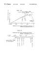
- FIG. 7is a graph showing a range within which the ration of ions can be controlled in a plasma etcher
- FIG. 8is a graph showing a range within which the ratio of ions can be controlled in a plasma CVD system
- FIG. 9is a schematic diagram showing a range within which the ratio of ions in a plasma can be controlled.
- FIG. 10is a cross-sectional diagram showing a first variation of a movable wall member.
- FIG. 11is a cross-sectional diagram showing a second variation of the movable wall member
- FIG. 12is a cross-sectional diagram showing a third variation of the movable wall member
- FIG. 13is a cross-sectional diagram showing a conventional plasma treatment system.
- FIG. 14is a cross-sectional diagram showing a condition in which a chamber of the conventional plasma treatment system is reduced in size.
- FIG. 1is a vertical cross-sectional diagram of principal parts of the system
- FIG. 2is a vertical cross-sectional perspective diagram showing a structure around a plasma producing chamber of the system
- FIG. 3is an enlarged diagram showing one of plasma producing spaces
- FIG. 5is a cross-sectional diagram showing a mounting condition in a vacuum chamber.
- This plasma etching systemgenerally comprises a parallel plate section (plasma treatment section) for providing a plasma treatment space, an adjoining mechanism section (plasma producing section) for providing the plasma producing spaces and its associated part, as well as field application circuit portion for applying electric or magnetic fields to individual masses of plasma.
- plasma treatment sectionfor providing a plasma treatment space
- adjoining mechanism sectionplasma producing section
- field application circuit portionfor applying electric or magnetic fields to individual masses of plasma.
- the parallel plate sectionincludes an anode portion 11 and a cathode portion 12 which are both metallic and together form a pair of parallel plates, in which the anode portion 11 is located in an upper position while the cathode portion 12 which serves as a substrate supporting structure whose top surface is insulated for loading a substrate 1 , such as a wager to be etched, is located in an lower position.
- a plasma treatment space 13is formed in a region sandwiched between the anode portion 11 and the cathode portion 12 .
- the anode portion 11has a number of readily formed connecting holes 14 which pass through the anode portion 11 , as well as treatment gas inlets 15 which serve as second gas intake channels opening to the plasma treatment space 13 .
- the ratio of the cross-sectional area of the connecting holes 14 to the effective cross-sectional area of the plasma treatment space 13 , or the first ratio,is set to 0.05.
- This exampleis so designed that a mixture of a reacting gas like silane gas and a proper amount of diluent gas is supplied as a treatment gas B.
- the adjoining mechanism sectionor the mechanism which adjoins one plate 11 of the pair of parallel plates, includes a plasma producing chamber 21 formed of an insulating material as a principal constituent part, and a plurality (four in the Figures) of annular grooves which constitute plasma producing spaces 22 are cut in the plasma producing chamber 21 in concentric form.
- the plasma producing spaces 22are dispersed or otherwise distributed in this configuration.
- the plasma producing chamber 21is firmly fixed, with an open side (underside in the Figures) of the plasma producing spaces 22 in tight contact with a top surface of the anode portion 11 . When fixed, the plasma producing chamber 21 is so positioned that openings of the plasma producing spaces 22 come in alignment with the connecting holes 14 of the anode portion 11 .
- the individual plasma producing spaces 22 and the plasma treatment space 13are made to adjoin one another and interconnect.
- the ratio of the cross-sectional area of the connecting holes 14 to the cross-sectional area of the plasma producing spaces 22is set to 0.5.
- an interface area through which each plasma producing space 22 is connected to the plasma treatment space 13is smaller than the cross-sectional area of each plasma producing space 22 and is somewhat narrowed.
- the value of this ratiomay be arbitrarily varied unless the relationship the values of the two cross-sectional areas is not inverted.
- the plasma producing chamber 21is constructed such that plasma producing gas feeding channels 23 , which serve as first gas intake channels, are formed also in annular form in the back of the individual plasma producing spaces 22 , with a number of small holes or nozzles interconnecting the plasma producing gas feeding channels 23 and the plasma producing spaces 22 , wherein the plasma producing gas feeding channels 23 are supplied with a plasma producing gas A composed on only a non-reactive gas constituent, such as argon, from their bottoms (upper side in the Figures), produce a high-density plasma 20 , and feed it into the plasma treatment space 13 through the connecting holes 14 .
- a plasma producing gas Acomposed on only a non-reactive gas constituent, such as argon
- a surface (top surface in the Figures) of the plasma producing chamber 21 opposite to the open side of the plasma producing spaces 22is cut away, leaving side walls which surround the plasma producing spaces 22 as well as their bottoms.
- Coils 24 and permanent magnet pieces 25are then fitted in annular arrays in a manner that they sandwich both side walls of each plasma producing space 22 .
- the permanent magnet pieces 25are arranged such that their magnetic poles are directed toward the plasma producing spaces 22 located at their side.
- the permanent magnet pieces 25are made of small pieces in order to eliminate undesirable induced currents which would otherwise flow along the annular form.
- a large number of permanent magnet pieces 25are arranged along the side walls of the plasma producing spaces 22 to form an annular magnetic circuit corresponding to the plasma producing spaces 22 .
- magnetic elements 25 for producing the magnetic circuitexcluding the elements in the outermost array, are arranged in regions sandwiched by the plasma producing spaces 22 . Magnetic force to be produced by the magnetic circuit would be sufficient if it is strong enough to just capture electrons of small mass, and such a strong magnetic force that would be sufficient to capture large-mass ions are not required.
- a cross section of the magnetic circuit(see FIG. 3) is now described in detail. Since lines of magnetic flux 26 departing from about an upper half of the vertically elongate permanent magnet pieces 25 return to the permanent magnet pieces 25 themselves, forming approximately concentric circles with their center located near an upper end of the permanent magnet pieces 25 , there is formed a protruding part of magnetic flux whose peak point is located at about the upper end of the permanent magnet pieces 25 . An almost identical protruding part of magnetic flux is formed around a lower end of the permanent magnet pieces 25 as well. Since the permanent magnet pieces 25 are mounted on both sides of each plasma producing space 22 , there are formed four protruding parts of magnetic flux around each plasma producing space 22 .
- the field application circuit portionis divided into two parts: a first field application circuit formed around an RF power supply 31 and a second field application circuit formed around an RF power supply 32 .
- the RF power supply 31is of a type whose output power is made variable. Its output is delivered to the cathode portion 12 through a blocking capacitor to produce an alternating electric field and to apply a bias voltage between the cathode portion 12 and the anode portion which is grounded. A power supply operating at a frequency of 500 kHz to 2 MHz is often used as the RF power supply 31 . In this configuration, the first field application circuit serves to apply an electric field which will more or less contribute to the enhancement of a cold plasma 10 across the plasma treatment space 13 .
- the RF power supply 32is also of a type whose output power is made variable. It drives two successive coils 24 sandwiching each plasma producing space 22 to apply an alternating magnetic field thereto.
- the RF power supply 32has a high output power rating and its operating frequency is set between 13 MHz and 100 MHz in most cases.
- the second field application circuitserves to apply a magnetic field which will more or less contribute to the production and enhancement of the high-density plasma 20 to the plasma producing spaces 22 .
- Configuration of pressure control meansis such that the variable valve 4 of the conventional system (see FIG. 13 ) is eliminated an, instead, a movable wall member 40 and a wall member drive mechanism 41 - 44 for vertically moving the movable wall member 40 are provided (see FIG. 5 ).
- the movable wall member 40is formed of a metallic cylindrical body with its inside diameter slightly larger than the outside diameter of the cathode portion 12 .
- the movable wall member 40is fitted over the cathode portion 12 in a manner that the cathode portion 12 can be slowly moved up and down.
- the movable wall member 40is disposed such that an approximately uniform clearance is formed all around its upper end when it comes into close proximity with the anode portion 11 .
- the movable wall member 40is formed to such a length that its upper part blocks all around side faces of the plasma treatment space 13 and its lower part reaches a point where the movable wall member 40 would not come off the cathode portion 12 .
- the movable wall member 40has such a shape that closes off an opening part of the plasma treatment space 13 defined with reference to the pair of parallel plates 11 - 12 disposed within a vacuum chamber 2 - 3 . To avoid undesirable charge-up, the movable wall member 40 is grounded, for instance.
- the wall member drive mechanismis constructed such that a bellows 41 having airtightness and a capability to extend and contract interconnect the bottom surface of a main vacuum chamber unit 2 and the movable wall member 40 at a position outside an intake opening 2 a , a ball screw 42 is vertically passed through the bellows 41 , and an upper end of the ball screw 42 is connected to the movable wall member 40 to support it in a manner that the movable wall member 40 can move up and down. Further, a lower end of the ball screw 42 is connected to a rotary shaft of a motor 44 which is fixed to the main vacuum chamber unit 2 by a support 43 .
- the ball screw 42When the motor 44 runs, the ball screw 42 is driven to extend and retract and, as a consequence, the movable wall member 40 is caused to move upward or downward between its uppermost point where the movable wall member 40 comes nearly in contact with the anode portion 11 and its lowermost point where the movable wall member 40 is located below the top surface of the cathode portion 12 .
- the wall member drive mechanism 41 - 44thus constructed serves to move the movable wall member 40 up and down all the way between its upper position where the movable wall member 40 covers the opening part of the plasma treatment space 13 and its lower position where the movable wall member 40 uncovers the opening part of the plasma treatment space 13 .
- a vacuum gage 4 bis fitted to the movable wall member 40 such that it can directly detect the pressure within the plasma treatment space 13 and a detection signal can be taken out through an internal cavity of the bellows 41 without breaking vacuum.
- the number of rotations and rotating speed of the motor 44are controlled by a PID control circuit 4 c as it receives the detection signal.
- the plasma etching systemis provided with the pressure control means for controlling the amount of upward and downward movements of the movable wall member 40 which is driven by the wall member drive mechanism 41 - 44 in accordance with the pressure within the plasma treatment space 13 .
- FIG. 5is a cross-sectional diagram showing the aforementioned condition is which principal parts are mounted to the vacuum chamber;
- FIGS. 6A-6Dare graphs showing energy distributions of electrons within plasmas;
- FIG. 7is a diagram showing a range within which the ratio of ions in a plasma can be controlled.
- the cathode portion 12Before operating the plasma etching system, its cathode portion 12 is mounted in the middle of the boxlike main vacuum chamber unit 2 which is open at the top with a lower support 12 a placed beneath the cathode portion 12 .
- the main vacuum chamber unit 2 fitted with the plasma producing chamber 21 and the anode portion 11can be cooled with water as well.
- the main vacuum chamber unit 2When the main vacuum chamber unit 2 is closed, its internal space as well as the plasma treatment space 13 and the plasma producing spaces 22 are also closed off. Then, the movable wall member 40 is lowered down to a point below the cathode portion 12 and, in this condition, a substrate 1 held in a horizontal position is introduced into the vacuum chamber 2 - 3 sideways and loaded on the top surface of the cathode portion 12 .
- a vacuum pump 5begins to create a vacuum.
- the vacuumis swiftly created within the vacuum chamber 2 - 3 because the gate valve 4 a is still left in its open position at this point and there exist no variable valve 4 .
- the motor 44is then run to raise the movable wall member 40 up to a point where the movable wall member 40 scarcely comes into contact with the anode portion 11 , and when the supply of the plasma producing gas A through the plasma producing gas feeding channels 23 and the supply of the treatment gas B through the treatment gas inlets 15 are commenced as appropriate, the pressure within the plasma treatment space 13 is maintained at a proper level by a throttling portion 49 formed between the upper end of the movable wall member 40 and a bottom surface of the anode portion 11 .
- the vacuum pressure within the plasma treatment space 13is detected by the vacuum gage 4 b attached to the movable wall member 40 , a control signal is generated by the PID control circuit 4 c based on the difference between a measurement value of the vacuum gage 4 b and a predefined target value, and the motor 44 runs to cause the ball screw 42 to extend or retract, thereby causing the movable wall member 40 to move upward or downward.
- the movable wall member 40is driven to descend. This causes the throttling portion 49 to somewhat broaden so that the pressure within the plasma treatment space 13 swiftly drops to restore a specified pressure.
- the movable wall member 40is driven to ascend. This causes the throttling portion 49 to somewhat constrict so that the pressure within the plasma treatment space 13 swiftly rises to restore the specified pressure.
- the vacuum pressure within the vacuum chamberis automatically controlled by the pressure control means which includes the movable wall member 40 and the wall member drive mechanism 41 - 44 as a pressure control mechanism to swiftly achieve the specified pressure in the above-described manner.
- the throttling portion 49is formed almost uniformly around an upper part of the plasma treatment space 13 . Since the flow of fluid streams including gases passing through the throttling portion 49 shows almost the same state at every point of the throttling portion 49 in accordance with the difference between the pressure inside the plasma treatment space 13 and the pressure within an internal space of the vacuum chamber outside the plasma treatment space 13 , the gas state of the gases within the plasma treatment space 13 becomes nearly symmetrical, exhibiting high uniformity. Furthermore, since such a controlled pressure condition is maintained even when a plasma has been formed within the plasma treatment space 13 , the state of the cold plasma 10 during an etching process, which will be described below, also becomes nearly symmetrical, exhibiting high uniformity.
- the ratio of ion species constituentsis high in the high-density plasma 20 .
- the high-density plasma 20which has expanded within the plasma producing spaces 22 , especially its radical species constituents and ion species constituents, is swiftly carried into the plasma treatment space 13 due to expansion pressure.
- the RF power supply 31When the RF power supply 31 is activated, an RF electric field is applied across the plasma treatment space 13 as well through the anode portion 11 and the cathode portion 12 . Since there is no magnetic circuit in the plasma treatment space 13 for confining the electrons, a high-density plasma is not created, but only the cold plasma 10 is produced, even when the treatment gas B or else is excited. If only the output power of the RF power supply 31 is applied, the ratio of radical species constituents becomes higher in the cold plasma 10 because it contains a small number of electrons with energies of 10 to 15 eV or over.
- the actual ratio between the radical species constituents and ion species constituentssettles to an intermediate value between the ratios in the cold plasma 10 and the high-density plasma 20 because the above-described high-density plasma 20 is mixed with the high-density plasma 20 .
- the output power of the RF power supply 32is increased, the number of electrons with energies of 10 to 15 eV or over within the plasma producing spaces 22 increases (see FIG. 6 B), resulting in an increase in the amount of production of the high-density plasma 20 .
- the ratio of ion species constituents in the cold plasma 10is increased.
- the output power of the RF power supply 32is decreased, the number of electrons with energies of 10 to 15 eV or over within the plasma producing spaces 22 decreases (see FIG. 6 C), resulting in a decrease in the amount of production of the high-density plasma 20 .
- the ratio of ion species constituents in the cold plasma 10is decreased.
- the density of electrons within the plasma treatment space 13becomes higher and their energies shifts toward the high-energy side as the output of the RF power supply 31 is increased (see alternate long and short dashed line in FIG. 6 D), resulting in an increase in the amount of cold plasma within the plasma treatment space 13 .
- Thiscauses an increase in the density of radicals within the plasma treatment space 13 , as well as a slight increase in the ratio of ions within the plasma treatment space 13 at the same time.
- a reduction in the output of the RF power supply 32causes the density of electrons within the plasma producing spaces 22 to become lower and their energies to shift toward the low-energy side (see alternate long and two short dashed line in FIG. 6 D).
- Thiscauses a decrease in the amount of high-density plasma within the plasma producing spaces 22 .
- the density of radicals and the ratio of ions within the plasma producing spaces 22decrease. Since the high-density plasma originally contains a large amount of high-density constituents, even a small reduction in the output power of the RF power supply 32 causes a significant decrease in the ratio of ions.
- the increase and the decrease in the ratio of ionsare roughly offset by each other, although the density of radicals increases.
- the density of plasma in the cold plasma 10is increased without any significant change in the ratio between the radical species constituents and ion species constituents.
- the outputs of the RF power supplies 31 , 32are increased or decreased in opposite directions, the plasma density in the cold plasma 10 is decreased.
- the ratio between the radical species constituents and ion species constituents in the cold plasma 10can easily be varied in a controlled manner as described above, and its variable range is so wide as to cover the variable ranges of almost all conventional models.
- FIG. 7It is to be noted that FIG. 7 and FIGS. 6A-6D provide schematic representations for explaining qualitative and relative characteristics.
- etching operationis carried out efficiently under optimum conditions for each etching process, or under conditions which have conventionally been difficult to achieve. (See point “a” in FIG. 7.)
- the outputs of the RF power supplies 31 , 32are properly adjusted. This adjustment can be performed automatically if its details are preset. After adjustment, the etching operation is carried out efficiently under the optimum conditions again. (See point “b” in FIG. 7.) It is therefore possible to always perform the etching operation in an efficient manner.
- the problem that the treatment gas B is directly excited by the high-density plasma 20 and decomposed and ionized to an undesirable levelis least likely to occur in this system.
- the reaction productis swiftly discharged without remaining within the plasma treatment space 13 even when its amount increases, because the region in which a gas pressure necessary for the plasma etching treatment is maintained is confined to a minimum space bounded by the anode portion 11 , the cathode portion 12 and the movable wall member 40 , and the internal space of the vacuum chamber surrounding that confined region is sufficiently evacuated to create a vacuum state.
- the plasma etching treatment which is excellent in quality and processing speedis maintained thanks to the supply of the high-quality plasma from the plasma producing spaces, for instance, combined with quick discharging of the reaction product by the movable wall member, for instance.
- a plasma deposition (CVD) systemis now described below.
- this systemmay be of generally the same construction as described above except for such differences that the cathode and the anode constituting facing electrodes are replaced with each other, monosilane or other active gas is used as a treatment gas B, the pressure within the plasma treatment space is set to a slightly higher level (low degree of vacuum), and so forth.
- the ratio between radical species constituents and ion species constituents in the cold plasma 10can easily be varied in a controlled manner in this case as well, and its variable range is so wide as to cover the variable ranges of almost all conventional models. (See FIG. 8.)
- deposition operationis carried out efficiently under optimum conditions for each deposition process, or under conditions which have conventionally been difficult to achieve. (see point “a” in FIG. 3.)
- This systemhas the same advantage as the earlier described system in that the deposition process can be carried out efficiently under the optimum conditions by properly adjusting the outputs of the RF Power supplies 31 , 32 when the optimum conditions have changed due to a change in the constituents of the treatment gas B, for instance.
- the aforementioned plasma treatment systemshave a wide variable range in which the ratio of ions within a plasma can be controllably varied and they cover almost all of the conventional plasma etching systems and plasma CVD systems as well as gaps between such conventional systems (See FIG. 9 ), it is possible to freely select and set optimum treatment conditions. As a consequence, it becomes possible to perform high-quality plasma treatment in an efficient manner.
- FIGS. 10 to 12are various variations in which the movable wall member 40 of the earlier described system is modified.
- the movable wall member 40is formed into such a shape that creates a gap which will serve as a throttle for the flow of fluid streams between the movable wall member 40 and the cathode portion (substrate supporting structure) 12 when the movable wall member 40 is raised and located at a position where it covers the opening part of the plasma treatment space 13 .
- the anode portion 11is modified so that it has the same outside diameter as the cathode portion 12 and the anode portion 11 can also be fitted into the internal cavity of the movable wall member 40 .
- a lower part of its internal cavityis broadened in a steplike fashion, with the lowest end of the movable wall member 40 a being supported by a ball screw 42 in such a way that the ball screw 42 and other components would not interfere with the cathode portion 12 , and a throttling portion 49 a acting on the fluid flow is formed between the lower end of a small-diameter part of the internal cavity and an upper peripheral part of the cathode portion 12 .
- a number of openings 49 bare formed in the movable wall member 40 b at a height corresponding to an upper peripheral part of the cathode portion 12 , in which throttles are formed at these openings 49 b in a dispersed fashion.
- an internal side surface 49 c of the movable wall member 40 cis rounded in order to reduce angular edges in the plasma treatment space 13 . This aims at relaxing the influence of nonuniformity which may be caused by a rapid change in fluid streams in the proximity of the openings 49 b.
- the present inventioncan provide basically the following four innovative plasma treatment systems.
- the first plasma treatment systemcomprises a plasma treatment section in which a plasma treatment space is formed and a plasma producing section in which plasma producing spaces are formed, the plasma producing section being affixed to or formed as a single piece with the plasma treatment section, wherein the plasma producing spaces are located adjacent to and connected to the plasma treatment space and are formed in a dispersed or otherwise distributed fashion.
- the second plasma treatment systemhas a pair of parallel plates which serve as facing electrodes in a vacuum chamber, and a plasma treatment space is formed between these parallel plates so that etching operation can be performed,, wherein plasma producing spaces which are located adjacent to and connected to the plasma treatment space are formed in a dispersed or otherwise distributed fashion in one of the pair of parallel plates or in its adjoining mechanism section.
- an entire plasma spaceis divided into the plasma producing spaces and the plasma treatment space, in which the plasma producing spaces are formed in a dispersed or otherwise distributed fashion and are located adjacent to and connected to the plasma treatment space.
- the above expression “in a dispersed or otherwise distributed fashion”refers not only to a configuration in which the plasma producing spaces are literally dispersed like scattered spots, but also to a configuration in which the plasma producing spaces are separated by some distances, not closely to one another, a configuration in which a plurality of plasma producing spaces are distributed in the form of lines, broken lines, straight or curved lines, or a mixture thereof in a portion adjacent to or connected to the plasma treatment space, as well as a configuration in which a number of plasma producing spaces shaped in annular, circular, polygonal or spiral form are arranged in concentric or nonconcentric arrays, or a single plasma producing space thus shaped is formed over a broad area.
- the basic requirements for reducing plasma damage and charge-up and for achieving a proper ratio between radical species constituents and ion species constituents within a plasmaare met by adhering to the prerequisites that the entire plasma space must be divided into separate spaces which are located adjacent to each other and interconnected.
- the plasma producing spacesare formed in a dispersed or otherwise distributed fashion, not only the requirements for ensuring the uniformity of plasma distribution are met, but the cross-sectional area of an adjoining surface between the plasma producing spaces and the plasma treatment space as well as that of the plasma producing spaces themselves taken along the adjoining surface naturally become smaller than the cross-sectional area of plasma treatment space. This is true not only for the whole cross section but also for partial cross sections of a central part and other parts.
- a first ratioas the ratio of the area of the adjoining surface to the cross-sectional area of the plasma treatment space taken along the adjoining surface and a second ratio as the ratio of the area of the adjoining surface to the cross-sectional area of the plasma producing spaces taken along the adjoining surface
- the first ratiois less than 1 and is smaller the second ratio when there is such a difference between the cross-sectional areas of the plasma treatment space and the plasma producing spaces.
- the first ratiois less than 1, the amount of gas following from the plasma treatment space into the plasma producing spaces decreases.
- the second ratiois 1, the amount of gas flowing from the plasma producing spaces into the plasma treatment space does not decrease. Even when the second ratio is less than 1 and the amount of gas flowing into the plasma treatment space decreases, the decrease can be rather small if the second ratio larger than the first ratio. In any case, the proportion of the gas flowing from the plasma producing spaces into the plasma treatment space becomes relatively larger than the proportion of the gas flowing from the plasma treatment space into the plasma producing spaces. As a consequence, the counterflow of the undesirable gas into the plasma producing spaces is reduced. Moreover, even when the gas has flown into the plasma producing spaces, it is swiftly discharged back to the plasma treatment space together with plasma streams, and this makes it possible to avoid or decrease a change in gas properties caused by a high-density plasma.
- the capability to achieve a proper plasma constituent ratio and controllabilityare positively increased by employing the aforementioned construction which prevents ion species from staying in the plasma producing spaces for a prolonged period of time by varying the ratio of the cross-sectional areas of the plasma producing spaces and the plasma treatment space.
- this constructioncan supply a high-quality plasma as it satisfies the requirements for both ensuring the uniformity of plasma distribution and preventing the gas from flowing from the plasma treatment space into the plasma producing spaces. As a consequence, it is made possible to perform high-density etching operation.
- the third plasma treatment systemhas a pair of parallel plates which serve as facing electrodes in a vacuum chamber, and a plasma treatment space is formed between these parallel plates so that etching operation can be performed.
- Plasma producing spaceswhich are located adjacent to and connected to the plasma treatment space are formed in one of the pair of parallel plates or in its adjoining mechanism section.
- the plasma producing spacesare associated with a magnetic circuit, at least part of magnetic elements for creating the magnetic circuit being disposed in a region surrounded or sandwiched by the plasma producing spaces.
- the basic requirements for reducing plasma damage and charge-up and for achieving a proper ratio between radical species constituents and ion species constituents within a plasmaare met by adhering to the prerequisites that the entire plasma space must be divided into separate spaces which are located adjacent to each other and interconnected.
- the localized magnetic circuitif it is constructed in a parallel configuration, for example, would also serve to meet the requirement for the uniformity of plasma. Moreover, the localization of the magnetic circuit is advantageous in that individual magnetic elements used for creating the magnetic circuit may be of a small and simple type which is easy to install, because the magnetic force produced by the whole magnetic circuit may be weak as a result of the localization. Further, a combination of this localized magnetic circuit with the aforementioned construction in which the plasma producing spaces are formed in a dispersed or otherwise distributed fashion would potentially produce such a combined effect that the undesirable gas which has flown in a reverse direction into the plasma producing spaces and ionized is swiftly returned to the plasma treatment space together with the high-density plasma before the properties of such undesirable gas are further changed.
- the capability to achieve a proper plasma constituent ratio and controllabilityare positively increased under specific preconditions.
- the above constructioncan supply a high-quality plasma as it satisfies the requirements for both ensuring the uniformity of plasma distribution and preventing the gas from flowing from the plasma treatment space into the plasma producing spaces. As a consequence, it is possible to allow high density etching operation.
- the fourth plasma treatment systemhas a pair of parallel plates which serve as facing electrodes in a vacuum chamber, and a plasma treatment space is formed between these parallel plates so that etching operation can be performed.
- Plasma producing spaceswhich are located adjacent to and connected to the plasma treatment space are formed in a dispersed or otherwise distributed fashion in one of the pair of parallel plates or in its adjoining mechanism section, and the plasma producing spaces are associated with a magnetic circuit for confining electrons.
- the fourth plasma treatment systempossesses advantageous effects of the aforementioned second and third plasma treatment systems. More specifically, the capability to achieve a proper plasma constituent ratio and controllability are positively increased and this construction can satisfy the requirements for both ensuring the uniformity of plasma distribution and preventing the gas from flowing from the plasma treatment space into the plasma producing spaces, because the aforementioned construction prevents ion species from staying in the plasma producing spaces for a prolonged period of time by varying the ratio of the cross-sectional areas of the plasma producing spaces and the plasma treatment space and securely confines the electrons within the plasma producing spaces.
- An advantageous effect accomplished as a resultis that it has been possible to realize a plasma treatment system which can supply a high-density plasma.
- the fourth plasma treatment systemmay be constructed such that the aforementioned plasma producing spaces are formed in linear form and a number of magnetic elements for creating the magnetic circuit are arranged in arrays sandwiching each plasma producing space from both sides.
- the plasma producing spacesare dispersed or otherwise distributed, they are formed rather continuously and, therefore, they provide a reasonably high capacity compared to the configuration in which the plasma producing spaces are dispersed in the form of scattered spots. Especially when the plasma producing spaces are configured in a spiral form, they have the unity as a single space. Thus, even when the plasma producing spaces are dispersed or otherwise distributed, the plasma within these spaces is made considerably uniform. Furthermore, the plasma producing spaces may be arranged in multiple annular form or multiple rectangular form, or such multiple arrays may be partially interconnected, and this makes it easy to disperse the plasma producing spaces to create a configuration suited to the shape of a particular substrate to be treated while maintaining the unity of the configuration.
- the magnetic circuitcan be created by arranging small magnet pieces on both sides of each plasma producing space so that electrons can easily be confined within the plasma producing spaces. This makes it easy to create the magnetic circuit. Since the plasma producing spaces are distributed while maintaining the unity of their configuration, it becomes possible to achieve the uniformity of the produced plasma and facilitate the design and production of the magnetic circuit.
- the magnetic circuitmay be formed by means of permanent magnets or an exciting coil. Since a high-power electromagnet is not required in this type of plasma treatment system, component mounting design becomes easier and the system can be made smaller. Moreover, production costs are reduced because not only is the high-power electromagnet required, but a high-capacity power supply for driving the high-power electromagnet becomes unnecessary. Especially when the permanent magnets are employed, they can be adapted to various magnetic circuit configurations only by arranging small magnet pieces of the same or similar shapes. This will not only help reduce the production costs but provide a significant improvement in the flexibility of design. Elimination of the need for the high-power electromagnet has provided such advantageous effects as simplification of design, reduction in size of the system, and cost reduction.
- first, second, third and fourth plasma treatment systemsmay be provided with a first field application circuit for applying an electric field or a magnetic field which contributes to the production or enhancement of plasma to the plasma treatment space and a second field application circuit for applying an electric field or a magnetic field which contributes to the production and enhancement of plasma to the plasma producing spaces.
- a first field application circuitfor applying an electric field or a magnetic field which contributes to the production or enhancement of plasma to the plasma treatment space
- a second field application circuitfor applying an electric field or a magnetic field which contributes to the production and enhancement of plasma to the plasma producing spaces.
- the output power of the first field application circuit and that of the second field application circuitmay be made independently controllable of each other.
- independently controllable of each othermeans that the outputs of the two circuits can be varied independently of each other if it is so desired, and does not mean that the two circuits can be adjusted regardless of the contents of control operation. Even when a certain coefficient or a mathematical function is preset and the outputs of the two circuits are related to each other by the coefficient or mathematical function, for example, the outputs are regarded as being independently controllable if the individual circuits adjust their outputs to match their respective target values based on the coefficient or mathematical function.
- the output power of the individual application circuitsis controlled independently of each other and, as a consequence, the plasma constituent ratio and the plasma density are set independently of each other. Stated another way, the density of ion species and the density of radical species are controlled and set independently of each other. Since treatment conditions can be arbitrarily chosen within a wide range of settings, it is possible to further improve the efficiency and quality of plasma treatment.
- first, second, third and fourth plasma treatment systemsmay be constructed such that the sectional area of a region connected to or opening to the plasma treatment space is smaller than the area of a cross section of the plasma producing spaces taken parallel to the aforementioned pair of parallel plates. Since each connecting part between the plasma producing spaces and the plasma treatment space is constricted and the first ratio becomes smaller compared to a configuration in which the plasma producing spaces are made to simply open to the plasma treatment space in this type of plasma treatment system, the flow of undesirable gas into the plasma producing spaces is further reduced.
- the first, second, third and fourth plasma treatment systemsmay be provided with a first gas intake channel for introducing a plasma producing gas into the plasma producing spaces and a second gas intake channel for introducing a treatment gas into the plasma treatment space.
- the plasma producing gasis introduced into the plasma producing spaces through the first gas intake channel while the treatment gas is introduced into the plasma treatment space through the separate second gas intake channel.
- the plasma producing gas necessary for the production of the high-density plasma and the treatment gas which will cause an undesirable effect when mixed into the high-density plasmaare separated from each other. What is particularly important is that the treatment gas is supplied to the plasma treatment space without passing through the plasma producing spaces, and the two kinds of gases are mixed only when a final stage has been reached. With this arrangement, it is possible to reliably prevent the treatment gas from being changed in properties by high-density plasma before the treatment gas is actually used for plasma treatment.
- the above plasma treatment systemsmay be such that only a gas containing a reactive gas constituent is supplied to the second gas intake channel whereas a gas containing a non-reactive gas constituent is supplied to the first gas intake channel.
- the treatment gascontains the reactive gas constituent necessary for etching operation while only the non-reactive gas constituent, which is useful for the production of the high-density plasma but will not be undesirably changed in properties even when the high-density plasma has been produced, is used.
- this arrangementit is possible to supply a higher-quality plasma compared to the configuration in which a reactive gas is supplied through the plasma producing spaces.
- the second, third and fourth plasma treatment systemsmay be provided with a movable wall member having such a shape that covers an opening part of the plasma treatment space defined with reference to the pair of parallel plates and a wall member drive mechanism for moving the movable wall member all the way between a position where the movable wall member covers the opening part and a position where the movable wall member uncovers the opening part, wherein one of the pair of parallel plates is installed directly on an internal bottom surface of the vacuum chamber or indirectly by way of a support member and has such a top surface that is shaped to allow a substrate to be loaded.
- the “opening part of the plasma treatment space defined with reference to the pair of parallel plates”refers to a side portion of a cylinder-shaped space whose both ends are defined by the two parallel plates.
- the expression “covers the opening part”means that the opening part is covered leaving a gap which will allow at least such portion of the plasma and gases that have already been used for treatment to be discharged but hold the remaining portion of the plasma, rather than completely closing off the opening part.
- the substrateis loaded-on the top surface of one of the parallel plates, the plasma treatment space is created above the substrate, and the plasma treatment is performed on the substrate in the plasma treatment space. Since the opening part of the plasma treatment space is covered by the movable wall member, the plasma treatment space is nearly enclosed by the pair of parallel plates and the movable wall member within the vacuum chamber. Part of the internal space of the vacuum chamber is then set apart as the plasma treatment space, and pressure conditions inside and outside the plasma treatment space are almost separated from each other. The degree of this pressure separation depends on the size of the gap left which is not covered by the movable wall member.
- the gapis broadened or narrowed, causing the pressure within the plasma treatment space to swiftly approach the vacuum pressure within the vacuum chamber or increase and go away from the vacuum pressure.
- the movable wall membercan be retracted by the wall member drive mechanism up to a position where the opening part of the plasma treatment space is uncovered when introducing the substrate into or removing it out of the vacuum chamber.
- the direct object of pressure control operationhas changed from the internal pressure of the vacuum chamber to that of the plasma treatment space which constitutes only part of the vacuum chamber, or from a large-capacity object with poor response to a small-capacity object with superior response.
- characteristics of the fluid floware no longer controlled by an intake opening in the wall of the vacuum chamber. Instead, the characteristics of the fluid flow are almost completely determined by the movable wall member by which a uniform distribution, such as symmetrical distribution around a middle point, can be achieved relatively easily. Thus, it becomes easier to improve pressure controllability within the plasma treatment space and achieve a uniform flow in the plasma treatment space at the same time.
- the shape of the movable wall membermay be such that a gap which will serve as a throttle acting on a fluid flow is created between the movable wall member and the aforementioned one parallel plate when the movable wall member is in the position where it covers the opening part.
- the treatment gas and other gases supplied from one side where one parallel plate on which the substrate is not loadedusually flow out of the plasma treatment space not along the same parallel plate but through a gap created around the other parallel plate during plasma treatment. For this reason, the flow tends to be aligned from top to bottom. This makes it possible to prevent the gases from flowing in a reverse direction and from staying in the plasma treatment space for a prolonged time period. It is therefore possible to further enhance the uniformity of the state of the plasma by employing-the aforementioned arrangement, in which the flow is aligned in the same direction.
- pressure control meansfor controlling the amount of movement of the movable wall member caused by the wall member drive mechanism in accordance with the pressure within the plasma treatment space.
- the pressure within the plasma treatment spaceis automatically controlled by the pressure control means so that a desired vacuum pressure is obtained. Since this automatic control operation is performed by controlling the amount of movement of the movable wall member which has good pressure controllability over the plasma treatment space, the state of the plasma swiftly and accurately follows a target value preset in the plasma treatment system. With this arrangement, a preset plasma reaction is performed in a reliable manner even when more detailed treatment conditions than before are set. It is therefore possible to perform more accurately controlled plasma treatment on the substrate.
- the plasma treatment system of this inventionis generally installed in an appropriate vacuum chamber when it is actually used. For this reason, one of the parallel plates between which the plasma treatment space adjacent to the plasma producing spaces is formed and its adjoining mechanism- section and other mechanisms are individually produced and assembled together, e.g., firmly fixed in tight contact with each other, in most cases from the viewpoint of balancing between the ease of installation into the vacuum chamber and the need of a high degree of vacuum. Part or the entirety of such components may be formed as a one-piece element by machining a single raw material such as a clad material.
Landscapes
- Chemical & Material Sciences (AREA)
- Engineering & Computer Science (AREA)
- Physics & Mathematics (AREA)
- Plasma & Fusion (AREA)
- Analytical Chemistry (AREA)
- Chemical Kinetics & Catalysis (AREA)
- General Chemical & Material Sciences (AREA)
- Materials Engineering (AREA)
- Mechanical Engineering (AREA)
- Metallurgy (AREA)
- Organic Chemistry (AREA)
- ing And Chemical Polishing (AREA)
- Plasma Technology (AREA)
Abstract
Description
Claims (19)
Applications Claiming Priority (2)
| Application Number | Priority Date | Filing Date | Title |
|---|---|---|---|
| JP5548997 | 1997-02-24 | ||
| JP9-055489 | 1997-02-24 |
Publications (1)
| Publication Number | Publication Date |
|---|---|
| US6267074B1true US6267074B1 (en) | 2001-07-31 |
Family
ID=13000053
Family Applications (1)
| Application Number | Title | Priority Date | Filing Date |
|---|---|---|---|
| US09/028,898Expired - LifetimeUS6267074B1 (en) | 1997-02-24 | 1998-02-24 | Plasma treatment systems |
Country Status (1)
| Country | Link |
|---|---|
| US (1) | US6267074B1 (en) |
Cited By (109)
| Publication number | Priority date | Publication date | Assignee | Title |
|---|---|---|---|---|
| US20030092278A1 (en)* | 2001-11-13 | 2003-05-15 | Fink Steven T. | Plasma baffle assembly |
| WO2003064725A1 (en)* | 2002-01-25 | 2003-08-07 | Applied Materials, Inc. | Gas distribution showerhead |
| US20040040833A1 (en)* | 2002-08-27 | 2004-03-04 | General Electric Company | Apparatus and method for plasma treating an article |
| US20040060514A1 (en)* | 2002-01-25 | 2004-04-01 | Applied Materials, Inc. A Delaware Corporation | Gas distribution showerhead |
| US6720260B1 (en)* | 2001-05-03 | 2004-04-13 | Novellus Systems, Inc. | Sequential electron induced chemical vapor deposition |
| US20040166695A1 (en)* | 2002-09-19 | 2004-08-26 | Applied Materials, Inc. | Limited thermal budget formation of PMD layers |
| US20050178746A1 (en)* | 2004-02-18 | 2005-08-18 | Gorin Georges J. | Higher power density downstream plasma |
| US6972071B1 (en)* | 1999-07-13 | 2005-12-06 | Nordson Corporation | High-speed symmetrical plasma treatment system |
| US20050269031A1 (en)* | 2002-04-19 | 2005-12-08 | Nordson Corporation | Plasma treatment system |
| US20060030165A1 (en)* | 2004-08-04 | 2006-02-09 | Applied Materials, Inc. A Delaware Corporation | Multi-step anneal of thin films for film densification and improved gap-fill |
| US20060254517A1 (en)* | 2005-05-04 | 2006-11-16 | Orlaw Massler | Plasma booster for plasma treatment installation |
| US20070059896A1 (en)* | 2002-09-19 | 2007-03-15 | Applied Materials, Inc. | Nitrous oxide anneal of teos/ozone cvd for improved gapfill |
| US20070148345A1 (en)* | 2003-03-25 | 2007-06-28 | Jean-Manuel Decams | Process for the deposition by cvd of a silver film on a substrate |
| US20070163503A1 (en)* | 2006-01-17 | 2007-07-19 | Mitsubishi Heavy Industries, Ltd. | Thin film preparation apparatus |
| US20070212850A1 (en)* | 2002-09-19 | 2007-09-13 | Applied Materials, Inc. | Gap-fill depositions in the formation of silicon containing dielectric materials |
| US20070212847A1 (en)* | 2004-08-04 | 2007-09-13 | Applied Materials, Inc. | Multi-step anneal of thin films for film densification and improved gap-fill |
| US20080050292A1 (en)* | 2006-08-28 | 2008-02-28 | Valery Godyak | Plasma reactor with inductie excitation of plasma and efficient removal of heat from the excitation coil |
| US20080050537A1 (en)* | 2006-08-22 | 2008-02-28 | Valery Godyak | Inductive plasma source with high coupling efficiency |
| US20080115726A1 (en)* | 2004-08-27 | 2008-05-22 | Applied Materials, Inc. | gap-fill depositions introducing hydroxyl-containing precursors in the formation of silicon containing dielectric materials |
| US7456116B2 (en) | 2002-09-19 | 2008-11-25 | Applied Materials, Inc. | Gap-fill depositions in the formation of silicon containing dielectric materials |
| EP1592043A3 (en)* | 2004-04-28 | 2009-07-01 | centrotherm photovoltaics AG | Device for measuring pressure for vacuum systems |
| US20100055342A1 (en)* | 2000-12-06 | 2010-03-04 | Novellus Systems, Inc. | Modulated ion-induced atomic layer deposition (mii-ald) |
| US20100323125A1 (en)* | 2008-02-18 | 2010-12-23 | Mitsui Engineering & Shipbuilding Co., Ltd | Atomic layer deposition apparatus and atomic layer deposition method |
| US7871678B1 (en) | 2006-09-12 | 2011-01-18 | Novellus Systems, Inc. | Method of increasing the reactivity of a precursor in a cyclic deposition process |
| US8053372B1 (en) | 2006-09-12 | 2011-11-08 | Novellus Systems, Inc. | Method of reducing plasma stabilization time in a cyclic deposition process |
| US8747964B2 (en) | 2010-11-04 | 2014-06-10 | Novellus Systems, Inc. | Ion-induced atomic layer deposition of tantalum |
| KR20140092406A (en)* | 2011-11-17 | 2014-07-23 | 램 리써치 코포레이션 | Distributed, non-concentric multi-zone plasma source systems, methods and apparatus |
| US8845816B2 (en) | 2011-03-01 | 2014-09-30 | Applied Materials, Inc. | Method extending the service interval of a gas distribution plate |
| US20150083582A1 (en)* | 2010-08-04 | 2015-03-26 | Lam Research Corporation | Ion to neutral control for wafer processing with dual plasma source reactor |
| US8992689B2 (en) | 2011-03-01 | 2015-03-31 | Applied Materials, Inc. | Method for removing halogen-containing residues from substrate |
| US9018108B2 (en) | 2013-01-25 | 2015-04-28 | Applied Materials, Inc. | Low shrinkage dielectric films |
| US20160163512A1 (en)* | 2014-12-09 | 2016-06-09 | Applied Materials, Inc. | Direct outlet toroidal plasma source |
| US9386677B1 (en)* | 2013-11-18 | 2016-07-05 | Georges J. Gorin | Plasma concentration apparatus and method |
| US9449793B2 (en) | 2010-08-06 | 2016-09-20 | Lam Research Corporation | Systems, methods and apparatus for choked flow element extraction |
| US20160307743A1 (en)* | 2015-04-17 | 2016-10-20 | Lam Research Corporation | Chamber with vertical support stem for symmetric conductance and rf delivery |
| US20170092470A1 (en)* | 2015-09-28 | 2017-03-30 | Applied Materials, Inc. | Plasma reactor for processing a workpiece with an array of plasma point sources |
| US9627183B2 (en) | 2013-10-30 | 2017-04-18 | Panasonic Intellectual Property Management Co., Ltd. | Plasma processing device, plasma processing method and method of manufacturing electronic devices |
| US9653264B2 (en) | 2010-12-17 | 2017-05-16 | Mattson Technology, Inc. | Inductively coupled plasma source for plasma processing |
| US9911578B2 (en) | 2009-12-03 | 2018-03-06 | Lam Research Corporation | Small plasma chamber systems and methods |
| US10134605B2 (en) | 2013-07-11 | 2018-11-20 | Lam Research Corporation | Dual chamber plasma etcher with ion accelerator |
| US10224221B2 (en) | 2013-04-05 | 2019-03-05 | Lam Research Corporation | Internal plasma grid for semiconductor fabrication |
| KR20190031110A (en)* | 2017-09-15 | 2019-03-25 | 가부시끼가이샤 도시바 | Shower head, processing apparatus, and shower plate |
| US10283325B2 (en) | 2012-10-10 | 2019-05-07 | Lam Research Corporation | Distributed multi-zone plasma source systems, methods and apparatus |
| US10297457B2 (en) | 2015-03-19 | 2019-05-21 | Mattson Technology, Inc. | Controlling azimuthal uniformity of etch process in plasma processing chamber |
| US10424464B2 (en) | 2015-08-07 | 2019-09-24 | Applied Materials, Inc. | Oxide etch selectivity systems and methods |
| US10453694B2 (en) | 2011-03-01 | 2019-10-22 | Applied Materials, Inc. | Abatement and strip process chamber in a dual loadlock configuration |
| US10468285B2 (en) | 2015-02-03 | 2019-11-05 | Applied Materials, Inc. | High temperature chuck for plasma processing systems |
| US10468267B2 (en) | 2017-05-31 | 2019-11-05 | Applied Materials, Inc. | Water-free etching methods |
| US10468282B2 (en) | 2011-03-01 | 2019-11-05 | Applied Materials, Inc. | Method and apparatus for substrate transfer and radical confinement |
| US10468276B2 (en) | 2015-08-06 | 2019-11-05 | Applied Materials, Inc. | Thermal management systems and methods for wafer processing systems |
| US10490406B2 (en) | 2018-04-10 | 2019-11-26 | Appled Materials, Inc. | Systems and methods for material breakthrough |
| US10490418B2 (en) | 2014-10-14 | 2019-11-26 | Applied Materials, Inc. | Systems and methods for internal surface conditioning assessment in plasma processing equipment |
| US10497573B2 (en) | 2018-03-13 | 2019-12-03 | Applied Materials, Inc. | Selective atomic layer etching of semiconductor materials |
| US10504754B2 (en) | 2016-05-19 | 2019-12-10 | Applied Materials, Inc. | Systems and methods for improved semiconductor etching and component protection |
| US10522371B2 (en) | 2016-05-19 | 2019-12-31 | Applied Materials, Inc. | Systems and methods for improved semiconductor etching and component protection |
| US10529737B2 (en) | 2017-02-08 | 2020-01-07 | Applied Materials, Inc. | Accommodating imperfectly aligned memory holes |
| US10541113B2 (en) | 2016-10-04 | 2020-01-21 | Applied Materials, Inc. | Chamber with flow-through source |
| US10541184B2 (en) | 2017-07-11 | 2020-01-21 | Applied Materials, Inc. | Optical emission spectroscopic techniques for monitoring etching |
| US10541246B2 (en) | 2017-06-26 | 2020-01-21 | Applied Materials, Inc. | 3D flash memory cells which discourage cross-cell electrical tunneling |
| US10546729B2 (en) | 2016-10-04 | 2020-01-28 | Applied Materials, Inc. | Dual-channel showerhead with improved profile |
| US10566205B2 (en) | 2012-02-29 | 2020-02-18 | Applied Materials, Inc. | Abatement and strip process chamber in a load lock configuration |
| US10573527B2 (en) | 2018-04-06 | 2020-02-25 | Applied Materials, Inc. | Gas-phase selective etching systems and methods |
| US10593560B2 (en) | 2018-03-01 | 2020-03-17 | Applied Materials, Inc. | Magnetic induction plasma source for semiconductor processes and equipment |
| US10593553B2 (en) | 2017-08-04 | 2020-03-17 | Applied Materials, Inc. | Germanium etching systems and methods |
| US10593523B2 (en) | 2014-10-14 | 2020-03-17 | Applied Materials, Inc. | Systems and methods for internal surface conditioning in plasma processing equipment |
| US10600639B2 (en) | 2016-11-14 | 2020-03-24 | Applied Materials, Inc. | SiN spacer profile patterning |
| RU2718132C1 (en)* | 2019-06-10 | 2020-03-30 | Акционерное общество "Научно-производственное предприятие "Электронное специальное-технологическое оборудование" | Device for plasma processing of semiconductor structures |
| US10607867B2 (en) | 2015-08-06 | 2020-03-31 | Applied Materials, Inc. | Bolted wafer chuck thermal management systems and methods for wafer processing systems |
| US10615047B2 (en) | 2018-02-28 | 2020-04-07 | Applied Materials, Inc. | Systems and methods to form airgaps |
| US10629473B2 (en) | 2016-09-09 | 2020-04-21 | Applied Materials, Inc. | Footing removal for nitride spacer |
| US10672642B2 (en) | 2018-07-24 | 2020-06-02 | Applied Materials, Inc. | Systems and methods for pedestal configuration |
| US10679870B2 (en) | 2018-02-15 | 2020-06-09 | Applied Materials, Inc. | Semiconductor processing chamber multistage mixing apparatus |
| US10699879B2 (en) | 2018-04-17 | 2020-06-30 | Applied Materials, Inc. | Two piece electrode assembly with gap for plasma control |
| US10727080B2 (en) | 2017-07-07 | 2020-07-28 | Applied Materials, Inc. | Tantalum-containing material removal |
| US10755941B2 (en) | 2018-07-06 | 2020-08-25 | Applied Materials, Inc. | Self-limiting selective etching systems and methods |
| US10770346B2 (en) | 2016-11-11 | 2020-09-08 | Applied Materials, Inc. | Selective cobalt removal for bottom up gapfill |
| US10854426B2 (en) | 2018-01-08 | 2020-12-01 | Applied Materials, Inc. | Metal recess for semiconductor structures |
| US10872778B2 (en) | 2018-07-06 | 2020-12-22 | Applied Materials, Inc. | Systems and methods utilizing solid-phase etchants |
| US10886137B2 (en) | 2018-04-30 | 2021-01-05 | Applied Materials, Inc. | Selective nitride removal |
| US10892198B2 (en) | 2018-09-14 | 2021-01-12 | Applied Materials, Inc. | Systems and methods for improved performance in semiconductor processing |
| US10903054B2 (en) | 2017-12-19 | 2021-01-26 | Applied Materials, Inc. | Multi-zone gas distribution systems and methods |
| US10903052B2 (en) | 2017-02-03 | 2021-01-26 | Applied Materials, Inc. | Systems and methods for radial and azimuthal control of plasma uniformity |
| US10920320B2 (en) | 2017-06-16 | 2021-02-16 | Applied Materials, Inc. | Plasma health determination in semiconductor substrate processing reactors |
| US10920319B2 (en) | 2019-01-11 | 2021-02-16 | Applied Materials, Inc. | Ceramic showerheads with conductive electrodes |
| US10943834B2 (en) | 2017-03-13 | 2021-03-09 | Applied Materials, Inc. | Replacement contact process |
| US10964512B2 (en) | 2018-02-15 | 2021-03-30 | Applied Materials, Inc. | Semiconductor processing chamber multistage mixing apparatus and methods |
| US11004689B2 (en) | 2018-03-12 | 2021-05-11 | Applied Materials, Inc. | Thermal silicon etch |
| US11024486B2 (en) | 2013-02-08 | 2021-06-01 | Applied Materials, Inc. | Semiconductor processing systems having multiple plasma configurations |
| US11049755B2 (en) | 2018-09-14 | 2021-06-29 | Applied Materials, Inc. | Semiconductor substrate supports with embedded RF shield |
| US11062887B2 (en) | 2018-09-17 | 2021-07-13 | Applied Materials, Inc. | High temperature RF heater pedestals |
| US11075057B2 (en)* | 2012-07-20 | 2021-07-27 | Plasma-Therm Llc | Device for treating an object with plasma |
| US11101136B2 (en) | 2017-08-07 | 2021-08-24 | Applied Materials, Inc. | Process window widening using coated parts in plasma etch processes |
| US11121002B2 (en) | 2018-10-24 | 2021-09-14 | Applied Materials, Inc. | Systems and methods for etching metals and metal derivatives |
| US11171008B2 (en) | 2011-03-01 | 2021-11-09 | Applied Materials, Inc. | Abatement and strip process chamber in a dual load lock configuration |
| US11239061B2 (en) | 2014-11-26 | 2022-02-01 | Applied Materials, Inc. | Methods and systems to enhance process uniformity |
| US11264213B2 (en) | 2012-09-21 | 2022-03-01 | Applied Materials, Inc. | Chemical control features in wafer process equipment |
| US11276590B2 (en) | 2017-05-17 | 2022-03-15 | Applied Materials, Inc. | Multi-zone semiconductor substrate supports |
| US11276559B2 (en) | 2017-05-17 | 2022-03-15 | Applied Materials, Inc. | Semiconductor processing chamber for multiple precursor flow |
| US11328909B2 (en) | 2017-12-22 | 2022-05-10 | Applied Materials, Inc. | Chamber conditioning and removal processes |
| US11417534B2 (en) | 2018-09-21 | 2022-08-16 | Applied Materials, Inc. | Selective material removal |
| US11437242B2 (en) | 2018-11-27 | 2022-09-06 | Applied Materials, Inc. | Selective removal of silicon-containing materials |
| US11476093B2 (en) | 2015-08-27 | 2022-10-18 | Applied Materials, Inc. | Plasma etching systems and methods with secondary plasma injection |
| US11594428B2 (en) | 2015-02-03 | 2023-02-28 | Applied Materials, Inc. | Low temperature chuck for plasma processing systems |
| CN116145110A (en)* | 2023-02-09 | 2023-05-23 | 深圳市原速光电科技有限公司 | Intake device and plasma equipment |
| US11682560B2 (en) | 2018-10-11 | 2023-06-20 | Applied Materials, Inc. | Systems and methods for hafnium-containing film removal |
| US11721527B2 (en) | 2019-01-07 | 2023-08-08 | Applied Materials, Inc. | Processing chamber mixing systems |
| WO2024112387A1 (en)* | 2022-11-21 | 2024-05-30 | Applied Materials, Inc. | Plasma generator for edge uniformity |
| US12057329B2 (en) | 2016-06-29 | 2024-08-06 | Applied Materials, Inc. | Selective etch using material modification and RF pulsing |
| US12340979B2 (en) | 2017-05-17 | 2025-06-24 | Applied Materials, Inc. | Semiconductor processing chamber for improved precursor flow |
Citations (9)
| Publication number | Priority date | Publication date | Assignee | Title |
|---|---|---|---|---|
| JPS6380522A (en) | 1986-09-24 | 1988-04-11 | Nec Corp | Excitation species cvd apparatus |
| US5113790A (en)* | 1991-03-23 | 1992-05-19 | Leybold Ag | Apparatus for the plasma treatment of substrates |
| JPH0855699A (en)* | 1994-08-11 | 1996-02-27 | Aneruba Kk | Plasma processing device |
| US5587039A (en)* | 1992-01-09 | 1996-12-24 | Varian Associates, Inc. | Plasma etch equipment |
| US5627435A (en)* | 1993-07-12 | 1997-05-06 | The Boc Group, Inc. | Hollow cathode array and method of cleaning sheet stock therewith |
| US5683548A (en)* | 1996-02-22 | 1997-11-04 | Motorola, Inc. | Inductively coupled plasma reactor and process |
| US5702530A (en)* | 1995-06-23 | 1997-12-30 | Applied Materials, Inc. | Distributed microwave plasma reactor for semiconductor processing |
| US5803973A (en)* | 1995-10-31 | 1998-09-08 | Balzers Und Leybold Deutschland Holding Ag | Apparatus for coating a substrate by chemical vapor deposition |
| US5976259A (en)* | 1985-02-14 | 1999-11-02 | Semiconductor Energy Laboratory Co., Ltd. | Semiconductor device, manufacturing method, and system |
- 1998
- 1998-02-24USUS09/028,898patent/US6267074B1/ennot_activeExpired - Lifetime
Patent Citations (9)
| Publication number | Priority date | Publication date | Assignee | Title |
|---|---|---|---|---|
| US5976259A (en)* | 1985-02-14 | 1999-11-02 | Semiconductor Energy Laboratory Co., Ltd. | Semiconductor device, manufacturing method, and system |
| JPS6380522A (en) | 1986-09-24 | 1988-04-11 | Nec Corp | Excitation species cvd apparatus |
| US5113790A (en)* | 1991-03-23 | 1992-05-19 | Leybold Ag | Apparatus for the plasma treatment of substrates |
| US5587039A (en)* | 1992-01-09 | 1996-12-24 | Varian Associates, Inc. | Plasma etch equipment |
| US5627435A (en)* | 1993-07-12 | 1997-05-06 | The Boc Group, Inc. | Hollow cathode array and method of cleaning sheet stock therewith |
| JPH0855699A (en)* | 1994-08-11 | 1996-02-27 | Aneruba Kk | Plasma processing device |
| US5702530A (en)* | 1995-06-23 | 1997-12-30 | Applied Materials, Inc. | Distributed microwave plasma reactor for semiconductor processing |
| US5803973A (en)* | 1995-10-31 | 1998-09-08 | Balzers Und Leybold Deutschland Holding Ag | Apparatus for coating a substrate by chemical vapor deposition |
| US5683548A (en)* | 1996-02-22 | 1997-11-04 | Motorola, Inc. | Inductively coupled plasma reactor and process |
Cited By (164)
| Publication number | Priority date | Publication date | Assignee | Title |
|---|---|---|---|---|
| US6972071B1 (en)* | 1999-07-13 | 2005-12-06 | Nordson Corporation | High-speed symmetrical plasma treatment system |
| US20100055342A1 (en)* | 2000-12-06 | 2010-03-04 | Novellus Systems, Inc. | Modulated ion-induced atomic layer deposition (mii-ald) |
| US9255329B2 (en) | 2000-12-06 | 2016-02-09 | Novellus Systems, Inc. | Modulated ion-induced atomic layer deposition (MII-ALD) |
| US7897215B1 (en) | 2001-05-03 | 2011-03-01 | Novellus Systems, Inc. | Sequential UV induced chemical vapor deposition |
| US6720260B1 (en)* | 2001-05-03 | 2004-04-13 | Novellus Systems, Inc. | Sequential electron induced chemical vapor deposition |
| US20030092278A1 (en)* | 2001-11-13 | 2003-05-15 | Fink Steven T. | Plasma baffle assembly |
| US20040060514A1 (en)* | 2002-01-25 | 2004-04-01 | Applied Materials, Inc. A Delaware Corporation | Gas distribution showerhead |
| US6793733B2 (en) | 2002-01-25 | 2004-09-21 | Applied Materials Inc. | Gas distribution showerhead |
| CN100342057C (en)* | 2002-01-25 | 2007-10-10 | 应用材料有限公司 | Gas distribution showerhead |
| WO2003064725A1 (en)* | 2002-01-25 | 2003-08-07 | Applied Materials, Inc. | Gas distribution showerhead |
| SG137728A1 (en)* | 2002-04-19 | 2007-12-28 | Nordson Corp | Plasma treatment system |
| US20050269031A1 (en)* | 2002-04-19 | 2005-12-08 | Nordson Corporation | Plasma treatment system |
| US8613827B2 (en) | 2002-04-19 | 2013-12-24 | Nordson Corporation | Plasma treatment system |
| US20040040833A1 (en)* | 2002-08-27 | 2004-03-04 | General Electric Company | Apparatus and method for plasma treating an article |
| US20040166695A1 (en)* | 2002-09-19 | 2004-08-26 | Applied Materials, Inc. | Limited thermal budget formation of PMD layers |
| US20070059896A1 (en)* | 2002-09-19 | 2007-03-15 | Applied Materials, Inc. | Nitrous oxide anneal of teos/ozone cvd for improved gapfill |
| US7674727B2 (en) | 2002-09-19 | 2010-03-09 | Applied Materials, Inc. | Nitrous oxide anneal of TEOS/ozone CVD for improved gapfill |
| US20070212850A1 (en)* | 2002-09-19 | 2007-09-13 | Applied Materials, Inc. | Gap-fill depositions in the formation of silicon containing dielectric materials |
| US7431967B2 (en) | 2002-09-19 | 2008-10-07 | Applied Materials, Inc. | Limited thermal budget formation of PMD layers |
| US7456116B2 (en) | 2002-09-19 | 2008-11-25 | Applied Materials, Inc. | Gap-fill depositions in the formation of silicon containing dielectric materials |
| US20070148345A1 (en)* | 2003-03-25 | 2007-06-28 | Jean-Manuel Decams | Process for the deposition by cvd of a silver film on a substrate |
| US20050178746A1 (en)* | 2004-02-18 | 2005-08-18 | Gorin Georges J. | Higher power density downstream plasma |
| US7015415B2 (en) | 2004-02-18 | 2006-03-21 | Dry Plasma Systems, Inc. | Higher power density downstream plasma |
| WO2005083741A1 (en)* | 2004-02-18 | 2005-09-09 | Dry Plasma Systems, Inc. | Higher power density downstream plasma |
| EP1592043A3 (en)* | 2004-04-28 | 2009-07-01 | centrotherm photovoltaics AG | Device for measuring pressure for vacuum systems |
| US20070212847A1 (en)* | 2004-08-04 | 2007-09-13 | Applied Materials, Inc. | Multi-step anneal of thin films for film densification and improved gap-fill |
| US20070000897A1 (en)* | 2004-08-04 | 2007-01-04 | Applied Materials, Inc. | Multi-step anneal of thin films for film densification and improved gap-fill |
| US20060030165A1 (en)* | 2004-08-04 | 2006-02-09 | Applied Materials, Inc. A Delaware Corporation | Multi-step anneal of thin films for film densification and improved gap-fill |
| US7642171B2 (en) | 2004-08-04 | 2010-01-05 | Applied Materials, Inc. | Multi-step anneal of thin films for film densification and improved gap-fill |
| US20080115726A1 (en)* | 2004-08-27 | 2008-05-22 | Applied Materials, Inc. | gap-fill depositions introducing hydroxyl-containing precursors in the formation of silicon containing dielectric materials |
| US7798097B2 (en)* | 2005-05-04 | 2010-09-21 | Oerlikon Trading Ag, Trubbach | Plasma booster for plasma treatment installation |
| US20060254517A1 (en)* | 2005-05-04 | 2006-11-16 | Orlaw Massler | Plasma booster for plasma treatment installation |
| US20070163503A1 (en)* | 2006-01-17 | 2007-07-19 | Mitsubishi Heavy Industries, Ltd. | Thin film preparation apparatus |
| US20100136262A1 (en)* | 2006-08-22 | 2010-06-03 | Valery Godyak | Inductive plasma source with high coupling efficiency |
| US20080050537A1 (en)* | 2006-08-22 | 2008-02-28 | Valery Godyak | Inductive plasma source with high coupling efficiency |
| US8920600B2 (en) | 2006-08-22 | 2014-12-30 | Mattson Technology, Inc. | Inductive plasma source with high coupling efficiency |
| US8444870B2 (en) | 2006-08-22 | 2013-05-21 | Mattson Technology, Inc. | Inductive plasma source with high coupling efficiency |
| US10037867B2 (en) | 2006-08-22 | 2018-07-31 | Mattson Technology, Inc. | Inductive plasma source with high coupling efficiency |
| US10090134B2 (en) | 2006-08-28 | 2018-10-02 | Mattson Technology, Inc. | Plasma reactor with inductive excitation of plasma and efficient removal of heat from the excitation coil |
| US8992725B2 (en) | 2006-08-28 | 2015-03-31 | Mattson Technology, Inc. | Plasma reactor with inductie excitation of plasma and efficient removal of heat from the excitation coil |
| US20080050292A1 (en)* | 2006-08-28 | 2008-02-28 | Valery Godyak | Plasma reactor with inductie excitation of plasma and efficient removal of heat from the excitation coil |
| US7871678B1 (en) | 2006-09-12 | 2011-01-18 | Novellus Systems, Inc. | Method of increasing the reactivity of a precursor in a cyclic deposition process |
| US8053372B1 (en) | 2006-09-12 | 2011-11-08 | Novellus Systems, Inc. | Method of reducing plasma stabilization time in a cyclic deposition process |
| US8607733B2 (en)* | 2008-02-18 | 2013-12-17 | Mitsui Engineering & Shipbuilding Co., Ltd. | Atomic layer deposition apparatus and atomic layer deposition method |
| US20100323125A1 (en)* | 2008-02-18 | 2010-12-23 | Mitsui Engineering & Shipbuilding Co., Ltd | Atomic layer deposition apparatus and atomic layer deposition method |
| US9911578B2 (en) | 2009-12-03 | 2018-03-06 | Lam Research Corporation | Small plasma chamber systems and methods |
| US20150083582A1 (en)* | 2010-08-04 | 2015-03-26 | Lam Research Corporation | Ion to neutral control for wafer processing with dual plasma source reactor |
| US9793126B2 (en)* | 2010-08-04 | 2017-10-17 | Lam Research Corporation | Ion to neutral control for wafer processing with dual plasma source reactor |
| US20180005852A1 (en)* | 2010-08-04 | 2018-01-04 | Lam Research Corporation | Ion to neutral control for wafer processing with dual plasma source reactor |
| US9967965B2 (en) | 2010-08-06 | 2018-05-08 | Lam Research Corporation | Distributed, concentric multi-zone plasma source systems, methods and apparatus |
| US9449793B2 (en) | 2010-08-06 | 2016-09-20 | Lam Research Corporation | Systems, methods and apparatus for choked flow element extraction |
| US8747964B2 (en) | 2010-11-04 | 2014-06-10 | Novellus Systems, Inc. | Ion-induced atomic layer deposition of tantalum |
| US9653264B2 (en) | 2010-12-17 | 2017-05-16 | Mattson Technology, Inc. | Inductively coupled plasma source for plasma processing |
| US8992689B2 (en) | 2011-03-01 | 2015-03-31 | Applied Materials, Inc. | Method for removing halogen-containing residues from substrate |
| US8845816B2 (en) | 2011-03-01 | 2014-09-30 | Applied Materials, Inc. | Method extending the service interval of a gas distribution plate |
| US11177136B2 (en) | 2011-03-01 | 2021-11-16 | Applied Materials, Inc. | Abatement and strip process chamber in a dual loadlock configuration |
| US11574831B2 (en) | 2011-03-01 | 2023-02-07 | Applied Materials, Inc. | Method and apparatus for substrate transfer and radical confinement |
| US11171008B2 (en) | 2011-03-01 | 2021-11-09 | Applied Materials, Inc. | Abatement and strip process chamber in a dual load lock configuration |
| US10453694B2 (en) | 2011-03-01 | 2019-10-22 | Applied Materials, Inc. | Abatement and strip process chamber in a dual loadlock configuration |
| US10468282B2 (en) | 2011-03-01 | 2019-11-05 | Applied Materials, Inc. | Method and apparatus for substrate transfer and radical confinement |
| KR20140092406A (en)* | 2011-11-17 | 2014-07-23 | 램 리써치 코포레이션 | Distributed, non-concentric multi-zone plasma source systems, methods and apparatus |
| US20180228015A1 (en)* | 2011-11-17 | 2018-08-09 | Lam Research Corporation | Distributed, Non-Concentric Multi-Zone Plasma Source Systems, Methods and Apparatus |
| US12094715B2 (en) | 2012-02-29 | 2024-09-17 | Applied Materials, Inc. | Abatement and strip process chamber in a load lock configuration |
| US10943788B2 (en) | 2012-02-29 | 2021-03-09 | Applied Materials, Inc. | Abatement and strip process chamber in a load lock configuration |
| US10566205B2 (en) | 2012-02-29 | 2020-02-18 | Applied Materials, Inc. | Abatement and strip process chamber in a load lock configuration |
| US11075057B2 (en)* | 2012-07-20 | 2021-07-27 | Plasma-Therm Llc | Device for treating an object with plasma |
| US11264213B2 (en) | 2012-09-21 | 2022-03-01 | Applied Materials, Inc. | Chemical control features in wafer process equipment |
| US10283325B2 (en) | 2012-10-10 | 2019-05-07 | Lam Research Corporation | Distributed multi-zone plasma source systems, methods and apparatus |
| US9018108B2 (en) | 2013-01-25 | 2015-04-28 | Applied Materials, Inc. | Low shrinkage dielectric films |
| US11024486B2 (en) | 2013-02-08 | 2021-06-01 | Applied Materials, Inc. | Semiconductor processing systems having multiple plasma configurations |
| US11171021B2 (en) | 2013-04-05 | 2021-11-09 | Lam Research Corporation | Internal plasma grid for semiconductor fabrication |
| US10224221B2 (en) | 2013-04-05 | 2019-03-05 | Lam Research Corporation | Internal plasma grid for semiconductor fabrication |
| US10134605B2 (en) | 2013-07-11 | 2018-11-20 | Lam Research Corporation | Dual chamber plasma etcher with ion accelerator |
| TWI647731B (en)* | 2013-09-20 | 2019-01-11 | 美商蘭姆研究公司 | Apparatus and method for etching a substrate |
| US9627183B2 (en) | 2013-10-30 | 2017-04-18 | Panasonic Intellectual Property Management Co., Ltd. | Plasma processing device, plasma processing method and method of manufacturing electronic devices |
| US9673062B1 (en) | 2013-10-30 | 2017-06-06 | Panasonic Intellectual Property Management Co., Ltd. | Plasma processing method |
| US9386677B1 (en)* | 2013-11-18 | 2016-07-05 | Georges J. Gorin | Plasma concentration apparatus and method |
| US10707061B2 (en) | 2014-10-14 | 2020-07-07 | Applied Materials, Inc. | Systems and methods for internal surface conditioning in plasma processing equipment |
| US10593523B2 (en) | 2014-10-14 | 2020-03-17 | Applied Materials, Inc. | Systems and methods for internal surface conditioning in plasma processing equipment |
| US10796922B2 (en) | 2014-10-14 | 2020-10-06 | Applied Materials, Inc. | Systems and methods for internal surface conditioning assessment in plasma processing equipment |
| US10490418B2 (en) | 2014-10-14 | 2019-11-26 | Applied Materials, Inc. | Systems and methods for internal surface conditioning assessment in plasma processing equipment |
| US11637002B2 (en) | 2014-11-26 | 2023-04-25 | Applied Materials, Inc. | Methods and systems to enhance process uniformity |
| US11239061B2 (en) | 2014-11-26 | 2022-02-01 | Applied Materials, Inc. | Methods and systems to enhance process uniformity |
| US10573496B2 (en)* | 2014-12-09 | 2020-02-25 | Applied Materials, Inc. | Direct outlet toroidal plasma source |
| US20160163512A1 (en)* | 2014-12-09 | 2016-06-09 | Applied Materials, Inc. | Direct outlet toroidal plasma source |
| US12009228B2 (en) | 2015-02-03 | 2024-06-11 | Applied Materials, Inc. | Low temperature chuck for plasma processing systems |
| US11594428B2 (en) | 2015-02-03 | 2023-02-28 | Applied Materials, Inc. | Low temperature chuck for plasma processing systems |
| US10468285B2 (en) | 2015-02-03 | 2019-11-05 | Applied Materials, Inc. | High temperature chuck for plasma processing systems |
| US10297457B2 (en) | 2015-03-19 | 2019-05-21 | Mattson Technology, Inc. | Controlling azimuthal uniformity of etch process in plasma processing chamber |
| US10395902B2 (en)* | 2015-04-17 | 2019-08-27 | Lam Research Corporation | Chamber with vertical support stem for symmetric conductance and RF delivery |
| US10665435B2 (en)* | 2015-04-17 | 2020-05-26 | Lam Research Corporation | Chamber with vertical support stem for symmetric conductance and RF delivery |
| US20160307743A1 (en)* | 2015-04-17 | 2016-10-20 | Lam Research Corporation | Chamber with vertical support stem for symmetric conductance and rf delivery |
| US20180323044A1 (en)* | 2015-04-17 | 2018-11-08 | Lam Research Corporation | Chamber with vertical support stem for symmetric conductance and rf delivery |
| US20190371579A1 (en)* | 2015-04-17 | 2019-12-05 | Lam Research Corporation | Chamber with vertical support stem for symmetric conductance and rf delivery |
| US10049862B2 (en)* | 2015-04-17 | 2018-08-14 | Lam Research Corporation | Chamber with vertical support stem for symmetric conductance and RF delivery |
| US10468276B2 (en) | 2015-08-06 | 2019-11-05 | Applied Materials, Inc. | Thermal management systems and methods for wafer processing systems |
| US10607867B2 (en) | 2015-08-06 | 2020-03-31 | Applied Materials, Inc. | Bolted wafer chuck thermal management systems and methods for wafer processing systems |
| US11158527B2 (en) | 2015-08-06 | 2021-10-26 | Applied Materials, Inc. | Thermal management systems and methods for wafer processing systems |
| US10424463B2 (en) | 2015-08-07 | 2019-09-24 | Applied Materials, Inc. | Oxide etch selectivity systems and methods |
| US10424464B2 (en) | 2015-08-07 | 2019-09-24 | Applied Materials, Inc. | Oxide etch selectivity systems and methods |
| US11476093B2 (en) | 2015-08-27 | 2022-10-18 | Applied Materials, Inc. | Plasma etching systems and methods with secondary plasma injection |
| US20170092470A1 (en)* | 2015-09-28 | 2017-03-30 | Applied Materials, Inc. | Plasma reactor for processing a workpiece with an array of plasma point sources |
| CN106558468A (en)* | 2015-09-28 | 2017-04-05 | 应用材料公司 | Using the plasma reactor of the ARRAY PROCESSING workpiece of plasma point source |
| US10957518B2 (en)* | 2015-09-28 | 2021-03-23 | Applied Materials, Inc. | Chamber with individually controllable plasma generation regions for a reactor for processing a workpiece |
| US10504754B2 (en) | 2016-05-19 | 2019-12-10 | Applied Materials, Inc. | Systems and methods for improved semiconductor etching and component protection |
| US11735441B2 (en) | 2016-05-19 | 2023-08-22 | Applied Materials, Inc. | Systems and methods for improved semiconductor etching and component protection |
| US10522371B2 (en) | 2016-05-19 | 2019-12-31 | Applied Materials, Inc. | Systems and methods for improved semiconductor etching and component protection |
| US12057329B2 (en) | 2016-06-29 | 2024-08-06 | Applied Materials, Inc. | Selective etch using material modification and RF pulsing |
| US10629473B2 (en) | 2016-09-09 | 2020-04-21 | Applied Materials, Inc. | Footing removal for nitride spacer |
| US11049698B2 (en) | 2016-10-04 | 2021-06-29 | Applied Materials, Inc. | Dual-channel showerhead with improved profile |
| US10546729B2 (en) | 2016-10-04 | 2020-01-28 | Applied Materials, Inc. | Dual-channel showerhead with improved profile |
| US10541113B2 (en) | 2016-10-04 | 2020-01-21 | Applied Materials, Inc. | Chamber with flow-through source |
| US10770346B2 (en) | 2016-11-11 | 2020-09-08 | Applied Materials, Inc. | Selective cobalt removal for bottom up gapfill |
| US10600639B2 (en) | 2016-11-14 | 2020-03-24 | Applied Materials, Inc. | SiN spacer profile patterning |
| US10903052B2 (en) | 2017-02-03 | 2021-01-26 | Applied Materials, Inc. | Systems and methods for radial and azimuthal control of plasma uniformity |
| US10529737B2 (en) | 2017-02-08 | 2020-01-07 | Applied Materials, Inc. | Accommodating imperfectly aligned memory holes |
| US10943834B2 (en) | 2017-03-13 | 2021-03-09 | Applied Materials, Inc. | Replacement contact process |
| US11915950B2 (en) | 2017-05-17 | 2024-02-27 | Applied Materials, Inc. | Multi-zone semiconductor substrate supports |
| US11361939B2 (en) | 2017-05-17 | 2022-06-14 | Applied Materials, Inc. | Semiconductor processing chamber for multiple precursor flow |
| US12340979B2 (en) | 2017-05-17 | 2025-06-24 | Applied Materials, Inc. | Semiconductor processing chamber for improved precursor flow |
| US11276590B2 (en) | 2017-05-17 | 2022-03-15 | Applied Materials, Inc. | Multi-zone semiconductor substrate supports |
| US11276559B2 (en) | 2017-05-17 | 2022-03-15 | Applied Materials, Inc. | Semiconductor processing chamber for multiple precursor flow |
| US10497579B2 (en) | 2017-05-31 | 2019-12-03 | Applied Materials, Inc. | Water-free etching methods |
| US10468267B2 (en) | 2017-05-31 | 2019-11-05 | Applied Materials, Inc. | Water-free etching methods |
| US10920320B2 (en) | 2017-06-16 | 2021-02-16 | Applied Materials, Inc. | Plasma health determination in semiconductor substrate processing reactors |
| US10541246B2 (en) | 2017-06-26 | 2020-01-21 | Applied Materials, Inc. | 3D flash memory cells which discourage cross-cell electrical tunneling |
| US10727080B2 (en) | 2017-07-07 | 2020-07-28 | Applied Materials, Inc. | Tantalum-containing material removal |
| US10541184B2 (en) | 2017-07-11 | 2020-01-21 | Applied Materials, Inc. | Optical emission spectroscopic techniques for monitoring etching |
| US10593553B2 (en) | 2017-08-04 | 2020-03-17 | Applied Materials, Inc. | Germanium etching systems and methods |
| US11101136B2 (en) | 2017-08-07 | 2021-08-24 | Applied Materials, Inc. | Process window widening using coated parts in plasma etch processes |
| KR20190031110A (en)* | 2017-09-15 | 2019-03-25 | 가부시끼가이샤 도시바 | Shower head, processing apparatus, and shower plate |
| US10837113B2 (en)* | 2017-09-15 | 2020-11-17 | Kabushiki Kaisha Toshiba | Shower head, processing apparatus, and shower plate |
| TWI711106B (en)* | 2017-09-15 | 2020-11-21 | 日商東芝股份有限公司 | Shower head, processing apparatus, and shower plate |
| US10903054B2 (en) | 2017-12-19 | 2021-01-26 | Applied Materials, Inc. | Multi-zone gas distribution systems and methods |
| US12148597B2 (en) | 2017-12-19 | 2024-11-19 | Applied Materials, Inc. | Multi-zone gas distribution systems and methods |
| US11328909B2 (en) | 2017-12-22 | 2022-05-10 | Applied Materials, Inc. | Chamber conditioning and removal processes |
| US10854426B2 (en) | 2018-01-08 | 2020-12-01 | Applied Materials, Inc. | Metal recess for semiconductor structures |
| US10861676B2 (en) | 2018-01-08 | 2020-12-08 | Applied Materials, Inc. | Metal recess for semiconductor structures |
| US10699921B2 (en) | 2018-02-15 | 2020-06-30 | Applied Materials, Inc. | Semiconductor processing chamber multistage mixing apparatus |
| US10679870B2 (en) | 2018-02-15 | 2020-06-09 | Applied Materials, Inc. | Semiconductor processing chamber multistage mixing apparatus |
| US10964512B2 (en) | 2018-02-15 | 2021-03-30 | Applied Materials, Inc. | Semiconductor processing chamber multistage mixing apparatus and methods |
| US10615047B2 (en) | 2018-02-28 | 2020-04-07 | Applied Materials, Inc. | Systems and methods to form airgaps |
| US10593560B2 (en) | 2018-03-01 | 2020-03-17 | Applied Materials, Inc. | Magnetic induction plasma source for semiconductor processes and equipment |
| US11004689B2 (en) | 2018-03-12 | 2021-05-11 | Applied Materials, Inc. | Thermal silicon etch |
| US10497573B2 (en) | 2018-03-13 | 2019-12-03 | Applied Materials, Inc. | Selective atomic layer etching of semiconductor materials |
| US10573527B2 (en) | 2018-04-06 | 2020-02-25 | Applied Materials, Inc. | Gas-phase selective etching systems and methods |
| US10490406B2 (en) | 2018-04-10 | 2019-11-26 | Appled Materials, Inc. | Systems and methods for material breakthrough |
| US10699879B2 (en) | 2018-04-17 | 2020-06-30 | Applied Materials, Inc. | Two piece electrode assembly with gap for plasma control |
| US10886137B2 (en) | 2018-04-30 | 2021-01-05 | Applied Materials, Inc. | Selective nitride removal |
| US10755941B2 (en) | 2018-07-06 | 2020-08-25 | Applied Materials, Inc. | Self-limiting selective etching systems and methods |
| US10872778B2 (en) | 2018-07-06 | 2020-12-22 | Applied Materials, Inc. | Systems and methods utilizing solid-phase etchants |
| US10672642B2 (en) | 2018-07-24 | 2020-06-02 | Applied Materials, Inc. | Systems and methods for pedestal configuration |
| US11049755B2 (en) | 2018-09-14 | 2021-06-29 | Applied Materials, Inc. | Semiconductor substrate supports with embedded RF shield |
| US10892198B2 (en) | 2018-09-14 | 2021-01-12 | Applied Materials, Inc. | Systems and methods for improved performance in semiconductor processing |
| US11062887B2 (en) | 2018-09-17 | 2021-07-13 | Applied Materials, Inc. | High temperature RF heater pedestals |
| US11417534B2 (en) | 2018-09-21 | 2022-08-16 | Applied Materials, Inc. | Selective material removal |
| US11682560B2 (en) | 2018-10-11 | 2023-06-20 | Applied Materials, Inc. | Systems and methods for hafnium-containing film removal |
| US11121002B2 (en) | 2018-10-24 | 2021-09-14 | Applied Materials, Inc. | Systems and methods for etching metals and metal derivatives |
| US11437242B2 (en) | 2018-11-27 | 2022-09-06 | Applied Materials, Inc. | Selective removal of silicon-containing materials |
| US11721527B2 (en) | 2019-01-07 | 2023-08-08 | Applied Materials, Inc. | Processing chamber mixing systems |
| US10920319B2 (en) | 2019-01-11 | 2021-02-16 | Applied Materials, Inc. | Ceramic showerheads with conductive electrodes |
| RU2718132C1 (en)* | 2019-06-10 | 2020-03-30 | Акционерное общество "Научно-производственное предприятие "Электронное специальное-технологическое оборудование" | Device for plasma processing of semiconductor structures |
| WO2024112387A1 (en)* | 2022-11-21 | 2024-05-30 | Applied Materials, Inc. | Plasma generator for edge uniformity |
| CN116145110A (en)* | 2023-02-09 | 2023-05-23 | 深圳市原速光电科技有限公司 | Intake device and plasma equipment |
Similar Documents
| Publication | Publication Date | Title |
|---|---|---|
| US6267074B1 (en) | Plasma treatment systems | |
| US11404249B2 (en) | Substrate processing apparatus | |
| US5935373A (en) | Plasma processing apparatus | |
| KR101184070B1 (en) | Apparatus for controlling gas flow in a semiconductor substrate processing chamber | |
| KR100774228B1 (en) | Plasma Processing System With Dynamic Gas Distribution Control | |
| EP1230666B1 (en) | Plasma processing systems and method therefor | |
| JP5074741B2 (en) | Vacuum processing equipment | |
| US20080260966A1 (en) | Plasma processing method | |
| US20100163186A1 (en) | Plasma Processing Apparatus | |
| JP4043089B2 (en) | Plasma processing equipment | |
| KR100842452B1 (en) | Plasma processing apparatus and electrode assembly for the plasma processing apparatus | |
| US20120190207A1 (en) | Plasma processing apparatus and plasma processing method | |
| US20080179183A1 (en) | Offset magnet compensation for non-uniform plasma | |
| EP1029099A2 (en) | Apparatus and method for adjusting density distribution of a plasma | |
| US20120168083A1 (en) | Plasma processing apparatus | |
| JP2008244233A (en) | Plasma processing equipment | |
| US7972469B2 (en) | Plasma processing apparatus | |
| JP4056144B2 (en) | Plasma processing equipment | |
| US20030047536A1 (en) | Method and apparatus for distributing gas within high density plasma process chamber to ensure uniform plasma | |
| JP4405496B2 (en) | Plasma processing equipment | |
| JP4527432B2 (en) | Plasma processing method and plasma processing apparatus | |
| US20240203701A1 (en) | Substrate processing apparatus and substrate processing method | |
| JP4405495B2 (en) | Plasma processing equipment | |
| JP2000156374A (en) | Plasma processing equipment for sputter processing | |
| JP4454034B2 (en) | Plasma processing equipment |
Legal Events
| Date | Code | Title | Description |
|---|---|---|---|
| AS | Assignment | Owner name:KABUSHIKI KAISHA KOBE SEIKO SHO, JAPAN Free format text:ASSIGNMENT OF ASSIGNORS INTEREST;ASSIGNOR:OKUMURA, YUTAKA;REEL/FRAME:009183/0592 Effective date:19980514 Owner name:FOI CORPORATION, JAPAN Free format text:ASSIGNMENT OF ASSIGNORS INTEREST;ASSIGNOR:OKUMURA, YUTAKA;REEL/FRAME:009183/0592 Effective date:19980514 | |
| AS | Assignment | Owner name:FOI CORPORATION, JAPAN Free format text:ASSIGNMENT OF ASSIGNORS INTEREST;ASSIGNOR:KABUSHIKI KAISHA KOBE SEIKO SHO;REEL/FRAME:011573/0690 Effective date:20010222 | |
| STCF | Information on status: patent grant | Free format text:PATENTED CASE | |
| FPAY | Fee payment | Year of fee payment:4 | |
| FPAY | Fee payment | Year of fee payment:8 | |
| AS | Assignment | Owner name:LAM RESEARCH CORPORATION, CALIFORNIA Free format text:ASSIGNMENT OF ASSIGNORS INTEREST;ASSIGNOR:FOI CORPORATION;REEL/FRAME:025000/0371 Effective date:20100915 | |
| FEPP | Fee payment procedure | Free format text:PAYOR NUMBER ASSIGNED (ORIGINAL EVENT CODE: ASPN); ENTITY STATUS OF PATENT OWNER: SMALL ENTITY Free format text:PAYER NUMBER DE-ASSIGNED (ORIGINAL EVENT CODE: RMPN); ENTITY STATUS OF PATENT OWNER: SMALL ENTITY | |
| FPAY | Fee payment | Year of fee payment:12 |