US6266940B1 - Insert for glazing unit - Google Patents
Insert for glazing unitDownload PDFInfo
- Publication number
- US6266940B1 US6266940B1US09/126,998US12699898AUS6266940B1US 6266940 B1US6266940 B1US 6266940B1US 12699898 AUS12699898 AUS 12699898AUS 6266940 B1US6266940 B1US 6266940B1
- Authority
- US
- United States
- Prior art keywords
- insert
- glazing
- spacer
- sheet
- sheets
- Prior art date
- Legal status (The legal status is an assumption and is not a legal conclusion. Google has not performed a legal analysis and makes no representation as to the accuracy of the status listed.)
- Expired - Lifetime
Links
Images


Classifications
- E—FIXED CONSTRUCTIONS
- E06—DOORS, WINDOWS, SHUTTERS, OR ROLLER BLINDS IN GENERAL; LADDERS
- E06B—FIXED OR MOVABLE CLOSURES FOR OPENINGS IN BUILDINGS, VEHICLES, FENCES OR LIKE ENCLOSURES IN GENERAL, e.g. DOORS, WINDOWS, BLINDS, GATES
- E06B3/00—Window sashes, door leaves, or like elements for closing wall or like openings; Layout of fixed or moving closures, e.g. windows in wall or like openings; Features of rigidly-mounted outer frames relating to the mounting of wing frames
- E06B3/66—Units comprising two or more parallel glass or like panes permanently secured together
- E06B3/663—Elements for spacing panes
- E06B3/66309—Section members positioned at the edges of the glazing unit
- E06B3/66361—Section members positioned at the edges of the glazing unit with special structural provisions for holding drying agents, e.g. packed in special containers
- E—FIXED CONSTRUCTIONS
- E06—DOORS, WINDOWS, SHUTTERS, OR ROLLER BLINDS IN GENERAL; LADDERS
- E06B—FIXED OR MOVABLE CLOSURES FOR OPENINGS IN BUILDINGS, VEHICLES, FENCES OR LIKE ENCLOSURES IN GENERAL, e.g. DOORS, WINDOWS, BLINDS, GATES
- E06B3/00—Window sashes, door leaves, or like elements for closing wall or like openings; Layout of fixed or moving closures, e.g. windows in wall or like openings; Features of rigidly-mounted outer frames relating to the mounting of wing frames
- E06B3/66—Units comprising two or more parallel glass or like panes permanently secured together
- E06B3/663—Elements for spacing panes
- E06B3/66309—Section members positioned at the edges of the glazing unit
- E06B3/66314—Section members positioned at the edges of the glazing unit of tubular shape
- E06B3/66319—Section members positioned at the edges of the glazing unit of tubular shape of rubber, plastics or similar materials
- E—FIXED CONSTRUCTIONS
- E06—DOORS, WINDOWS, SHUTTERS, OR ROLLER BLINDS IN GENERAL; LADDERS
- E06B—FIXED OR MOVABLE CLOSURES FOR OPENINGS IN BUILDINGS, VEHICLES, FENCES OR LIKE ENCLOSURES IN GENERAL, e.g. DOORS, WINDOWS, BLINDS, GATES
- E06B3/00—Window sashes, door leaves, or like elements for closing wall or like openings; Layout of fixed or moving closures, e.g. windows in wall or like openings; Features of rigidly-mounted outer frames relating to the mounting of wing frames
- E06B3/66—Units comprising two or more parallel glass or like panes permanently secured together
- E06B3/663—Elements for spacing panes
- E06B3/66309—Section members positioned at the edges of the glazing unit
- E06B3/66366—Section members positioned at the edges of the glazing unit specially adapted for units comprising more than two panes or for attaching intermediate sheets
- E—FIXED CONSTRUCTIONS
- E06—DOORS, WINDOWS, SHUTTERS, OR ROLLER BLINDS IN GENERAL; LADDERS
- E06B—FIXED OR MOVABLE CLOSURES FOR OPENINGS IN BUILDINGS, VEHICLES, FENCES OR LIKE ENCLOSURES IN GENERAL, e.g. DOORS, WINDOWS, BLINDS, GATES
- E06B3/00—Window sashes, door leaves, or like elements for closing wall or like openings; Layout of fixed or moving closures, e.g. windows in wall or like openings; Features of rigidly-mounted outer frames relating to the mounting of wing frames
- E06B3/66—Units comprising two or more parallel glass or like panes permanently secured together
- E06B3/663—Elements for spacing panes
- E06B3/66309—Section members positioned at the edges of the glazing unit
- E06B2003/66395—U-shape
- E—FIXED CONSTRUCTIONS
- E06—DOORS, WINDOWS, SHUTTERS, OR ROLLER BLINDS IN GENERAL; LADDERS
- E06B—FIXED OR MOVABLE CLOSURES FOR OPENINGS IN BUILDINGS, VEHICLES, FENCES OR LIKE ENCLOSURES IN GENERAL, e.g. DOORS, WINDOWS, BLINDS, GATES
- E06B3/00—Window sashes, door leaves, or like elements for closing wall or like openings; Layout of fixed or moving closures, e.g. windows in wall or like openings; Features of rigidly-mounted outer frames relating to the mounting of wing frames
- E06B3/66—Units comprising two or more parallel glass or like panes permanently secured together
- E06B3/663—Elements for spacing panes
- E06B3/66309—Section members positioned at the edges of the glazing unit
- E06B3/66323—Section members positioned at the edges of the glazing unit comprising an interruption of the heat flow in a direction perpendicular to the unit
Definitions
- This inventionrelates to multiple-pane glazing units. More particularly, this invention relates to glazing units and methods for forming glazing units having a substantially U-shaped moisture and gas impervious spacer. Specifically, this invention relates to an insert that is adapted to fit within the U-shaped spacer in multiple-pane glazing units.
- a multiple-pane glazing unitincludes a pair of outer glazing sheets spaced apart by a spacer disposed about the perimeter of the glazing sheets.
- the two glazing sheetscooperate with the spacer to form an insulating sealed air cavity.
- This cavitymay be filled with an inert gas having a lower conductivity than air to improve the insulating properties of the multiple-pane sealed glazing unit.
- One or more intermediate glazing sheetsmay be held by the edge assembly in a substantially parallel relation to the outer glazing sheets.
- the intermediate glazing sheetdivides the single cavity into a pair of cavities to add a further layer of insulation between the outside atmosphere and the inside atmosphere.
- Custom-sized glazing unitsmay be made by hand in small-scale operations by cutting the glazing sheets to size and manually positioning the edge assemblies about their perimeters.
- Automated machineryhas, however, developed in recent times that substantially decreases the amount of time required to fabricate a custom-sized glazing unit. Such automated machines are expensive and thus force a company to use the machine for many years to justify its purchase.
- a glazing unit that can be produced by one such automated processis described in U.S. pat. No. 5,531,047 to Leopold et al.
- the glazing unit disclosed in this patentincludes a pair of outer glazing sheets secured to the outer legs of a spacer having a generally U-shaped cross section. On the interior face of the spacer between the outer legs, a layer of pliable material having a desiccant material therein is provided. This combination is known as a desiccant matrix.
- the edge of a third or intermediate glazing sheetis disposed in a groove formed in the layer of pliable material.
- Movement of the intermediate sheetis limited by the cooperation of the layer of the pliable material and a portion of the outer legs of the spacer at the corners of the unit which are bent inwardly to move the layer of pliable material at the corner toward the intermediate sheet during fabrication of the unit.
- One problem with the glazing units produced by these automated processesis that the desiccant matrix is pumped into the glazing units by sealant pumps. This process uses a relatively large amount of energy because the desiccant matrix may require heating prior to being pumped and the pumps require energy to operate. These pumps also wear out quickly because the desiccant is highly abrasive. The high energy use and frequent replacement and repair of the sealant pumps increases the cost of the automated process. It is thus desired in the art to provide a glazing unit and a method for manufacturing the glazing unit that does not require the desiccant matrix to be pumped in during the process. Another problem with the glazing unit described above is that some types of the desiccant matrix used inside the U-shaped spacer remain flowable after the glazing unit is fabricated. On hot days when the sun heats the interior of the glazing unit, the desiccant matrix may flow along the intermediate sheet and degrade the appearance of the glazing unit.
- the automated process using the substantially U-shaped metal spacerhas gained broad industry acceptance and is particularly successful with two-sheet glazing units.
- the automated processis capable of quickly and efficiently fabricating the two-sheet glazing units in a variety of sizes.
- the automated processhas not, however, achieved great commercial success for glazing units that have more than two glazing sheets.
- This lack of commercial successionis attributed to the fact that creating glazing units having more than two glazing sheets with the automated process is significantly more time consuming than the time that it takes to create a glazing unit having two glazing sheets.
- the increase in the amount of time to create the glazing unitis chiefly attributed to the fact that the intermediate glazing sheet must be precisely placed in the groove formed in the layer of pliable material on the first attempt. Such precise placement is especially difficult because the intermediate glazing sheets are positioned by hand.
- the difficulty of this taskincreases with the size of the glazing unit and the speed of the automated line.
- the intermediate glazing sheetmust be precisely placed in the groove because it cannot be easily adjusted once its edge engages the pliable material. If the intermediate glazing sheet contacts the pliable material and is then removed, the pliable material must be cleaned from the edge of the glazing sheet prior to replacing the sheet in the spacer. Furthermore, some portions of the U-shaped spacer may be left without a sufficient amount of pliable material if enough of the pliable material adheres to the edge of the glazing sheet during the first attempt to place it in the spacer. It is thus desired in the art to provide an apparatus and method for assembling a glazing unit that decreases the difficulty in installing the intermediate glazing sheet and allows the position of the intermediate glazing sheet to be adjusted with respect to the spacer after it has been positioned.
- Another undesirable aspect of the glazing unit disclosed in the patentis that the two cavities formed between the intermediate glazing sheet and the outer glazing sheets are sealed from each other by the interaction of the desiccant matrix and the intermediate glazing sheet.
- the intermediate glazing sheetexperiences stresses caused by changes in pressure in the individual cavities brought on by temperature changes and/or barometric changes.
- the force of wind against one of the outer glazing sheetscan also alter the pressure in the individual cavities creating stresses on the intermediate glazing sheet.
- Past solutions to the problem of separately sealed cavitiesinclude providing a breathing tube between the cavities or drilling a hole in the intermediate glazing sheet to provide fluid communication between the cavities. It is, however, desirable to provide a spacer that receives an intermediate glazing sheet such that the two cavities formed by the intermediate glazing sheet and the outer glazing sheets are in fluid communication without requiring either of these past solutions.
- the intermediate glazing sheetis positioned through the cooperation of a pair of bent portions at the corners of the spacer with the pliable material such that the bent portions push the pliable material into the intermediate glazing sheet to center it within the spacer.
- This method of positioningdoes not easily allow the intermediate glazing sheet to be positioned closer to one of the outer glazing sheets than the other.
- the offset of the intermediate glazing sheetcan provide an acoustic benefit to the glazing unit as well as positioning the intermediate glazing sheet away from the screw that holds the spacer together. It is thus desired in the art to provide an insert for the spacer of the above-described glazing unit that overcomes these deficiencies and problems created by the desiccant matrix.
- Another objective of the present inventionis to provide an insert having an aesthetically pleasing appearance.
- Another objective of the present inventionis to provide an insert that may be formed in different colors to allow one to select the appearance of the glazing unit.
- Still another objective of the present inventionis to provide an insert that slidably receives an intermediate glazing sheet in a channel allowing the intermediate glazing sheet to be repositioned during assembly of the glazing unit allowing the glazing unit to be easily assembled.
- Yet another objective of the present inventionis to provide an insert that creates fluid communication between the cavities formed between the intermediate glazing sheet and the outer glazing sheets.
- a further objective of the present inventionis to provide an insert that increases the insulating properties of the edge assembly.
- Still a further objective of the present inventionis to provide an insert that may be configured allowing the intermediate glazing sheet to be positioned closer to one of the outer glazing sheets than the other to improve the sound barrier properties of the unit.
- Another objective of the present inventionis to provide an insert that may be configured to position the intermediate glazing sheet in a position that causes the screw that is used to hold the spacer together to avoid contacting the intermediate glazing sheet.
- Yet a further objective of the present inventionis to provide an insert that includes an outwardly facing channel that receives the screw used to hold the spacers together.
- Another objective of the present inventionis to provide an insert that includes inwardly facing thermal channels that increase the insulating properties of the edge assembly by lengthening the conductive path across the unit.
- a further objective of the present inventionis to provide an insert including a desiccant material that is in fluid communication with the cavities formed between the intermediate glazing sheet and the outer glazing sheets.
- Another objective of the present inventionis to provide an insert that is configured to be fabricated from a low volume of material while substantially blocking the view of the interior of the spacer while also holding the position of the intermediate glazing sheet.
- a further objective of the present inventionis to provide an insert that is configured to be flexible so that it may fit into a range of different-sized spacers.
- Another objective of the present inventionis to provide an insert for a glazing unit that includes the desiccant material in the insert so that the desiccant does not have to be pumped into the glazing unit by sealant pumps.
- Another objective of the present inventionis to provide an insert for a glazing unit that creates separate insulating air pockets inside the spacer.
- Another objective of the present inventionis to provide a method for assembling a glazing unit with the insert of the present invention.
- Another objective of the present inventionis to provide an insert for a glazing unit that is of simple construction, that achieves the stated objectives in a simple, effective, and inexpensive manner; and that solves the problems and that satisfies the needs existing in the art.
- the insert for a glazing unithaving at least two outer glazing sheets separated by a substantially rigid, U-shaped spacer disposed about the perimeter of the sheets to create an interior cavity between the outer sheets and the spacer, the spacer having a longitudinal length dimension substantially equal to the perimeter of the glazing sheets;
- the general nature of the insertmay be stated as including a body having a width and a height, the width and height of the body adapted to fit within the U-shaped spacer; the body having an inner surface, an outer surface, and a pair of side surfaces; the body having a longitudinal length dimension substantially equal to the length of the spacer; and the body being fabricated from a non-flowable material having substantially stable dimensions.
- a glazing unitincluding a pair of outer glazing sheets; an intermediate glazing sheet disposed between the outer glazing sheets; a spacer extending about the peripheries of the glazing sheets; an insert disposed within the spacer, the insert being fabricated from a non-flowable material having substantially stable dimensions; and the insert having at least one longitudinal, inwardly-facing glazing sheet-receiving channel, the intermediate glazing sheet being seated in the channel.
- a method for manufacturing a glazing unitincluding the steps of providing at least two outer glazing sheets and at least one intermediate glazing sheet; providing a U-shaped, substantially rigid spacer having a base with two spaced legs, the outer surface of the spacer being covered with an adhesive; inserting an insert into the spacer, the insert being fabricated from a non-flowable material having substantially stable dimensions; folding the U-shaped spacer around the other three sides of intermediate glazing sheet; placing the outer glazing sheets on the frame such that the outer glazing sheets contact the adhesive; and pressing the outer glazing sheets towards each other to form a sealed glazing unit.
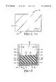
- FIG. 1is a front elevational view of a glazing unit incorporating the insert of the present invention
- FIG. 2is a sectional view taken along line 2 — 2 of FIG. 1;
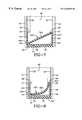
- FIG. 3is a sectional view similar to FIG. 2 showing an alternative embodiment of the invention
- FIG. 4is a sectional view similar to FIG. 2 showing another alternative embodiment of the invention.
- FIG. 5is a sectional view similar to FIG. 2 showing an alternative embodiment of the invention positioned in the spacer of a glazing unit;
- FIG. 6is a sectional view similar to FIG. 5 showing the alternative embodiment of FIG. 5 positioned in a spacer smaller than the spacer of FIG. 5;
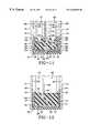
- FIG. 7is a sectional view similar to FIG. 2 showing an alternative embodiment of the insert of the invention positioned in a spacer;
- FIG. 8is a view similar to FIG. 7 showing the alternative embodiment of FIG. 7 positioned in a smaller spacer than the spacer of FIG. 7;
- FIG. 9is a sectional view similar to FIG. 2 showing an alternative embodiment of the insert having an inwardly facing glazing sheet-receiving channel seating an intermediate glazing sheet;
- FIG. 10is a view of an alternative embodiment of the insert depicted in FIG. 7 having an outwardly facing screw-receiving channel;
- FIG. 11is another alternative embodiment of the insert depicted in FIG. 10 having inwardly facing thermal channels;
- FIG. 12is a view similar to FIG. 2 showing another alternative embodiment of the insert wherein the glazing sheet-receiving channel is positioned closer to one of the outer glazing sheets than the other;
- FIG. 13is a view similar to FIG. 2 showing another alternative embodiment of the insert wherein the insert has a pair of inwardly facing glazing sheet-receiving channels in combination with a pair of intermediate glazing sheets;
- FIG. 14is a view similar to FIG. 2 showing another alternative embodiment of the insert
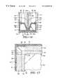
- FIG. 15is a view similar to FIG. 2 showing another alternative embodiment of the insert with retaining slots that connect the insert to the spacer;
- FIG. 16is a view similar to FIG. 2 showing another alternative embodiment of the insert
- FIG. 17is an enlarged elevational view of the final corner of the glazing unit with part of the spacer removed for clarity;
- FIG. 18is a schematic side view of an initial step in the assembly method of the present invention.
- FIG. 19is a schematic side view of another step of the assembly method of the present invention.
- FIG. 20is a schematic side view of yet another step of the assembly method of the present invention.
- FIG. 21is a schematic sectional view depicting still another step of the method of the present invention.
- Glazing unit 10includes a pair of outer glazing sheets 12 and 14 separated by a U-shaped spacer 16 .
- Spacer 16is fabricated from a substantially rigid material such as metal, plastic, or oriented thermoplastic. Although plastic and thermoplastic have more desirable heat transfer characteristics than metal, metal may be less expensive to use and easier to form during an automated process than the plastics.
- Spacer 16includes a substantially planar base 18 with a pair of spaced, substantially parallel outer legs 20 extending from the outer edges of base 18 .
- Each outer leg 20includes a distal edge 22 and a proximal edge 24 with the proximal edge connected to base 18 .
- An inwardly-extending lip 26extends from distal edge 22 of each leg 20 .
- Each lip 26is sized to create a protuberance in the U-shaped channel of spacer 16 but is short enough to allow an insert 30 to be fit within the U-shaped channel.
- Spacer 16is held between outer glazing sheets 12 and 14 with an adhesive 32 that is disposed between each outer leg 20 and glazing sheets 12 and 14 .
- Adhesive 32also fills an outwardly facing channel formed between the outer surface 34 of spacer 16 and the inner surfaces 36 and 38 of outer glazing sheets 12 and 14 .
- Adhesive 32 and spacer 16cooperate to seal the interior cavity 40 of glazing unit 10 from the atmosphere outside glazing sheets 12 and 14 .
- Cavity 40may be filled with an inert gas that provides desirable heat transfer characteristics.
- Insert 30is fabricated from a non-flowable material such that it has substantially stable dimensions after it has been formed.
- Insert 30may be manufactured from thermoplastic or thermosetting plastics.
- Suitable thermosetting plasticsinclude silicone, EPDM, and polyurethane.
- Suitable thermoplastic materialsinclude thermoplastic elastomers such as Santoprene, Kraton, or cross-linked polyethylene.
- One preferred materialis silicone foam.
- the advantages of the silicone foaminclude: good durability, minimal outgassing, low compression set, good resilience, high temperature stability, and cold temperature flexibility.
- a further advantage of the silicone foamis that the material is moisture permeable such that moisture vapor can easily reach a desiccant material disposed within the foam or underneath the foam.
- Other significant advantages of silicone foamare that it is UV resistant and may be fabricated in a wide variety of different colors.
- desiccant material 42is added during the production of the foam as a fill.
- the type of desiccant material usedmay be any of the various desiccants known in the art. Overall, the amount of desiccant material to be used should match the amount of desiccant material that is typically incorporated in a conventional sealed glazing unit.
- desiccant material 42is dispersed as a layer between the outer surface 46 of insert 30 and inner surface 48 of spacer 16 .
- the permeability of insert 30allows desiccant material 42 to be in fluid communication with cavity 40 .
- desiccant material 42is dispersed in a layer adjacent inner surface 44 of insert 30 .
- insert 30has a width substantially equal to the width of base 18 and a height substantially equal to outer legs 20 such that insert 30 fits snugly within U-shaped channel of spacer 16 but may slide with respect to the channel.
- Outer surface 46 and the side surfaces 50 of insert 30are, however, substantially smooth and non-tacky such that they slidably engage the inner surfaces of spacer 16 .
- Insert 30may thus be installed by sliding it into spacer 16 .
- Insert 30may thus be adjusted within spacer 16 after it has been installed within spacer 16 by sliding it back and forth.
- Lips 26engage inner surface 44 of insert 30 to retain insert 30 in spacer 16 .
- Insert 30is flexible enough to fit between lips 26 and resilient enough to spring back and substantially fill U-shaped channel of spacer 16 .
- Insert 30improves the insulating properties of spacer 16 by substantially filling spacer 16 with a material that has desirable thermal properties. In the past, spacer 16 was not filled with a material that provided better thermal properties than the material filling cavity 40 . Insert 30 improves the heat transfer characteristics of glazing unit 10 by improving the thermal performance of spacer 16 .
- Insert 30also improves the visual appearance of the interior of spacer 16 .
- Inner surface 44 of insert 30provides a relatively smooth, clean surface to be viewed through outer glazing sheets 12 and 14 .
- Insert 30may be provided in a variety of colors that are more pleasing in appearance than the appearance of the interior of spacer 16 .
- Insert 30may be provided in a warm color that blocks the cold appearance of the metal of spacer 16 from view giving the consumer the appearance of a warm edge in glazing unit 10 .
- Insert 230is preferably fabricated from a material that is more dense and rigid than the materials from which insert 30 is fabricated. Insert 230 may be combined with any of the desiccant matrix positions depicted in FIGS. 2-4 and may preferably hold the desiccant within its perimeter.
- insert 230has a substantially rectangular cross section with a width that is substantially greater than its thickness.
- the width of insert 230is adapted to fit within spacer 16 such that the edges 232 of insert 230 contact legs 20 .
- the contactcreates a frictional force between insert 230 and legs 20 that at least partially helps to hold the position of insert 230 with respect to spacer 16 .
- the dimensions of insert 230require it to be deformed before it can be placed in spacer 16 .
- the material from which insert 230 is fabricatedcauses insert 230 to spring back toward its original shape when the force deforming insert 230 is removed. As such, insert 230 provides an outwardly directed force against each leg 20 once insert 230 is properly positioned.
- insert 230is further held with respect to spacer 16 by a strip of adhesive 235 that is positioned between insert 230 and base 18 of spacer 16 .
- Adhesive 235may be connected to insert 230 when it is fabricated with a thin layer of material protecting its lower surface during storage and transport. The protective layer is then peeled off and discarded when insert 230 is installed into spacer 16 . Any one of the numerous known adhesives may be used to perform this function.
- Insert 230improves the visual appearance of the interior of spacer 16 when insert 230 is installed in spacer 16 .
- the inner surface 234 of insert 230provides a relatively smooth, clean surface to be viewed through outer glazing sheets 12 and 14 .
- Insert 230may be provided in a variety of colors that are more pleasing in appearance that the appearance of the interior of spacer 16 .
- Insert 230may be preferably provided in a warm color that blocks the cold appearance of the metal of spacer 16 .
- Insert 230may be fabricated from a significantly lower volume of material than insert 30 . This aspect of insert 230 makes it inexpensive to fabricate in large quantities. Another desirable feature of insert 230 can be understood by comparing FIGS. 5 and 6.
- the spacer 16 of FIG. 6has a width that is somewhat less than the width of spacer 16 in FIG. 5 . Although the width of the spacers is different, the same size insert 230 may be used in both applications.
- the flexibility or bendability of insert 230allows it to be used with spacers in a given size range.
- the upper limit of the size rangeis determined by the overall width of insert 230 .
- a lower limit of the size rangeis determined by the point at which the bend in insert 230 causes damage to insert 230 .
- This desirable aspect of insert 230allows the manufacturer to keep an inventory and eliminates some of the expense of fabricating different sizes of insert 230 .
- the window manufactureralso benefits by being able to keep fewer sizes of insert 230 on hand during the window fabrication process.
- Insert 240is preferably fabricated from the same material described above with respect to insert 230 . Insert 240 may also be combined with any of the desiccant matrix positions depicted in FIGS. 2-4 and may preferably hold the desiccant within its perimeter.
- insert 240has a substantially rectangular cross section with a width that is substantially greater than its thickness.
- the width of insert 240is adapted to cause insert 240 to fit within spacer 16 at an angle with the edges 242 of insert 240 disposed in opposite corners of spacer 16 . Spacer 240 is thus held in position without the use of adhesive 235 or other connecting devices.
- insert 240The dimensions of insert 240 require it to be deformed before it can be placed in spacer 16 .
- the material from which insert 240 is fabricatedcauses insert to spring back towards its original shape when the force deforming insert 240 is removed. As such, insert 240 provides an outwardly directed force against each leg 20 once insert 240 is properly positioned.
- Insert 240improves the visual appearance of the interior of spacer 16 when insert 240 is installed in spacer 16 .
- the inner surface 244 of insert 230provides a relatively smooth, clean surface to be viewed through outer glazing sheets 12 and 14 .
- Insert 240may be provided in a variety of colors that are more pleasing in appearance than the appearance of the interior of spacer 16 .
- Insert 240may be preferably provided in a warm color that blocks the cold appearance of the metal spacer 16 .
- Insert 240may be fabricated from a significantly lower volume of material than insert 230 . As described above with respect to insert 230 , the lower volume of material makes insert 240 relatively inexpensive to fabricate in large quantities and thus desired in the industry. Another similarity with respect to insert 230 is that insert 240 may be adapted to fit within spacers having different widths. This adaptability can be seen by comparing FIGS. 7 and 8 where FIG. 8 depicts insert 240 fit into a spacer 16 having a width that is somewhat smaller than the width of the spacer 16 depicted in FIG. 7 . When insert 240 is placed in the smaller spacer 16 , insert 240 is bent with its ends 242 remaining in the opposite corners of spacer 16 .
- Insert 60is fabricated from one of the same materials as insert 30 of FIGS. 2 through 4. Insert 60 may also be combined with any of the desiccant positions depicted in FIGS. 2-4. Insert 60 has an intermediate glazing sheet-receiving channel 62 formed in the inner surface 64 of insert 60 . Channel 62 is longitudinally disposed in insert 60 and opens toward the interior of glazing unit 10 . An intermediate glazing sheet 66 is disposed between outer glazing sheets 12 and 14 and is held in position by channel 62 . The material from which insert 60 is fabricated is strong enough to support intermediate glazing sheet 66 without being crushed or deformed.
- Intermediate glazing sheet 66slidably engages channel 62 such that it may be positioned after it is installed within channel 62 .
- the location of channel 62also positions intermediate glazing sheet 66 at the desired location between outer glazing sheets 12 and 14 .
- channel 62is centrally disposed in insert 60 such that intermediate glazing sheet 66 is disposed at an equal distance from either outer glazing sheet 12 or 14 .
- Insert 60prevents intermediate glazing sheet 66 from moving out of position within glazing unit 10 because the material has stable dimensions.
- the sidewalls of channel 62cooperate to maintain the desired position of intermediate glazing sheet 66 .
- Channel 62may be configured to loosely receive intermediate glazing sheet 66 such that sheet 66 may be easily positioned and repositioned in channel 62 .
- channel 62is greater than the thickness of intermediate glazing sheet 66 such that intermediate glazing sheet 66 may be easily fit into channel 62 .
- the sidewalls of channel 62may also be angled away from intermediate glazing sheet 66 to provide easy entry of intermediate glazing sheet 66 into channel 62 .
- Channel 62thus greatly decreases the difficulty in positioning intermediate glazing sheet 66 in spacer 16 .
- a person using insert 60can place intermediate glazing sheet 66 in channel 62 in any location and then slide it into the correct position. Sheet 66 may also be lifted out of channel 62 and repositioned without cleaning intermediate glazing sheet 66 because insert 60 is fabricated from a non-flowable material with stable dimensions.
- intermediate glazing sheet 66When positioned within channel 62 , intermediate glazing sheet 66 forms a first cavity 68 between outer glazing sheet 12 and intermediate glazing sheet 66 and a second cavity 70 between outer glazing sheet 14 and intermediate glazing sheet 66 .
- First cavity 68is in fluid communication with second cavity 70 because intermediate glazing sheet 66 slidably engages channel 62 and allows fluid communication about its outer edge 72 .
- First cavity 68is also in fluid communication with the second cavity 70 because insert 60 does not extend continuously about the entire glazing unit 10 .
- a gap 73is provided between the ends 75 of insert 60 that allows air to move freely between cavities 68 and 70 . The air moves through gap 73 and around the corner of intermediate glazing sheet 66 as can be seen in FIG. 17 .
- Such fluid communicationallows the pressure in cavities 68 and 70 to be equalized.
- Insert 60also retains the characteristics of insert 30 in that insert 60 also slidably engages spacer 16 . Insert 60 also improves the insulating properties of glazing unit 10 because intermediate glazing sheet 66 is separated from spacer 16 by a portion of insert 60 and thus does not contact metal. Furthermore, insert 60 provides a pleasing aesthetic appearance to glazing unit 10 by substantially filling spacer 16 around intermediate glazing sheet 66 .
- FIG. 9also depicts a screw 80 that is used to assemble spacer 16 .
- Spacer 16is assembled by providing a tongue 81 on one end of spacer 16 that is slid back into spacer 16 so that the perimeter of spacer 16 may be fixed.
- Screw 80extends through spacer 16 and through tongue 81 and into the body of insert 60 .
- adhesive 32completely surrounds the head of screw 80 to seal the hole in spacer 16 .
- screw 80is inserted into spacer 16 and insert 60 , the threads of screw 80 can damage insert 60 . Screw 80 must thus be carefully inserted to avoid such damage. Screw 80 can also cause the material to bulge outwardly giving it an undesirable appearance. It is desired that insert 60 be configured such that no portion of screw plug 80 contacts intermediate glazing sheet 66 or extends completely into either cavity 68 or 70 .
- Insert 82includes inwardly facing, intermediate glazing sheet-receiving channel 62 in its inner surface 64 .
- An intermediate glazing sheet 66is received in channel 62 forming a first cavity 68 between intermediate glazing sheet 66 and outer glazing sheet 12 as well as a second cavity 70 between intermediate glazing sheet 66 and outer glazing sheet 14 .
- Insert 82also includes an outwardly facing screw-receiving channel 84 .
- Channel 84also extends longitudinally through insert 82 and opens through outer surface 74 of insert 82 .
- Channel 84is sized and positioned to receive the threaded portion of screw 80 .
- Insert 90includes inwardly facing glazing sheet-receiving channel 62 in its inwardly facing surface 64 .
- An intermediate glazing sheet 66is received within channel 62 and is positioned by channel 62 .
- Insert 90further includes outwardly facing screw plug receiving channel 84 which receives the threaded portion of screw 80 .
- outwardly facing channel 84has tapered sidewalls.
- Insert 90is configured to more easily fit within spacer 16 .
- Outer comers 92 of insert 90are chamfered to allow insert 90 to be fit more easily between lips 26 of spacer 16 .
- Chamfered corners 92also allow insert 90 to be formed with less material.
- Insert 90also includes a pair of thermal channels 94 that open into first and second cavities 68 and 70 through inner surface 64 .
- each thermal channel 94is substantially V-shaped having a relatively flat lower surface.
- thermal channels 94may have different cross sections and need not be identically shaped. Thermal channels 94 improve the insulating characteristics of glazing unit 10 by providing a longer heat path and convection traps to glazing unit 10 .
- the convection trapsfunction by interfering with the flow of cold air from one of outer glazing sheets 12 to the other of outer glazing sheets 14 .
- the heat flowschematically depicted in FIG. 11 by the arrows labeled by numeral 96 .
- a portion of the cold airfalls into thermal channel 94 and is trapped there as indicated by the arrow indicated by numeral 98 .
- Thermal channels 94increase the heat path of insert 90 by increasing the distance over inner surface of insert 90 from outer glazing sheet 12 to outer glazing sheet 14 .
- FIG. 12Another embodiment of the insert of the present invention is depicted in FIG. 12 is indicated generally by the numeral 100 .
- This embodimentis similar to the embodiment of the invention depicted in FIG. 9 except that inwardly facing channel 62 is non-centrally disposed in insert 100 .
- Inwardly facing glazing sheet-receiving channel 62is non-centrally disposed such that the width of cavity 68 is substantially greater than the width of second cavity 70 . It is desirable to locate intermediate glazing sheet 66 a distance from the center of insert 100 to improve the sound barrier properties of glazing unit 10 . An acoustic resonance may be prevented by positioning intermediate glazing sheet 66 off center.
- Insert 110is substantially similar to the other embodiments of the inserts described above. Insert 110 , however, includes two inwardly facing sheet-receiving channels 112 and 114 . An intermediate glazing sheet 116 and 118 is positioned within each inwardly facing channel 112 and 114 . Intermediate glazing sheets 116 and 118 cooperate with outer glazing sheets 12 and 14 to form first, second, and third cavities 120 , 122 , and 124 . The additional cavity provides an extra layer of insulation to glazing unit 10 . The distances between channels 112 and 114 may also be altered to be unequal to provide improved acoustic properties to glazing unit 10 . Insert 110 may also have outwardly facing channels (not shown) that may receive screws.
- Insert 250may be fabricated from the same foam material discussed above with respect to the other embodiments of the present invention or may be fabricated from a denser plastic as discussed with respect to the embodiment of the invention depicted in FIGS. 5 and 6. Insert 250 is designed to securely retain and position intermediate glazing sheet 66 within spacer 16 while being fabricated from a relatively low volume of material. To this end, a pair of large voids 252 are provided in insert 250 on either side of a sheet-receiving channel 254 . Each void 252 substantially parallels the perimeter of insert 250 such that the wall thickness of insert 250 is substantially constant. In other embodiments of the present invention, voids 252 may be configured differently to provide different wall thickness where strength is required in insert 250 . Voids 252 further provide insulating pockets in insert 250 that improve the thermal properties of insert 250 .
- Insert 250is sized and adapted to fit snugly within spacer 16 where it is held by lips 26 .
- the lower corners of insert 250are chamfered with angled corners 256 to allow insert 250 to be more easily fit within spacer 16 .
- Sheet-receiving channel 254includes a bottom wall 258 that is substantially parallel to base 18 of spacer 16 .
- a pair of channel sidewalls 260extend up from bottom wall 258 at angles. The angular disposition of sidewalls 260 make it easier for the user to install intermediate glazing sheets 66 in insert 250 during the manufacturing process.
- sheet-receiving 254may have substantially parallel sidewalls.
- Insert 300may be fabricated from the same materials as in the embodiments described above but is preferably fabricated from a denser plastic such that a relatively low volume of material must be used to fabricate insert 300 . Instead of the voids 252 as described above with respect to insert 250 , insert 300 is supported on lips 26 of spacer 16 and leaves the large corner areas 302 unfilled. This configuration allows insert 300 to occupy a small volume while providing all of the benefits of the inserts described above. Insert 300 includes a sheet-receiving channel 304 that has a bottom wall 306 that is substantially parallel to base 18 of spacer 16 .
- the sidewalls 308 of channel 304are angled in the preferred embodiment to allow intermediate glazing sheet 66 to be easily positioned within channel 304 during the assembly process.
- side walls 308may be substantially parallel.
- side walls 308may be angled at different angles to locate bottom wall 306 closer to one of glazing sheets 12 or 14 as desired to alter the acoustic properties of glazing unit 10 .
- Insert 300extends above each lip 26 with a cover member 310 .
- Each cover member 310extends over the top of a lip 26 and continues out to inner surfaces 36 and 38 of outer glazing sheets 12 and 14 .
- Cover member 310thus prevents adhesive 32 from extending up past lips 26 .
- Cover members 310further prevent adhesive 32 from being viewed by the person looking into glazing unit 10 .
- Insert 300further includes a pair of insert retaining members 312 that extend down from cover members 310 to latch around the lips 26 .
- Cover members 310 and retaining members 312are configured to provide an insert retaining slot 314 that is sized and configured to receive a lip 26 to securely anchor insert 300 within spacer 16 .
- Insert 350may be fabricated from any of the materials discussed above but is preferably fabricated from a denser plastic having a memory such that it springs back to its original position.
- Insert 350includes an angled sheet-receiving channel 352 that includes a bottom wall 354 and a pair of angled side walls 356 . As discussed above, angled side walls 356 may extend from bottom wall 354 at equal or unequal angles to position intermediate glazing sheets 66 in its desired location.
- Insert 350includes a pair of top walls 358 that are disposed substantially parallel to base 18 in the embodiment of the invention depicted in FIG. 16 .
- Upper walls 358are configured to fit under lips 26 to retain insert 350 within spacer 16 .
- Insert 350is further configured to flex and fit within a range of different sized spacers as discussed above with respect to insert 230 discussed above with respect to FIGS. 5 and 6. Thus, insert 350 may be inserted into a spacer 16 having a smaller width than the spacer 16 depicted in FIG. 16 .
- upper walls 358move toward each other and change the angle of each side wall 356 with respect to bottom wall 354 . It is intended that insert 350 only be used in spacers 16 of sizes that prevent side walls 356 from pinching intermediate glazing sheets 66 when insert 350 is installed in spacer 16 .
- each of the inserts of the present inventionis configured to slidably engage spacer 16 so that their position may be adjusted in spacer 16 after they have been installed.
- each of the insertsmay contain desiccant material, may be used with a desiccant material disposed along their inner surfaces 64 or their outer surfaces 74 .
- Each insertmay also be fabricated from a foam or a dense material.
- Glazing unit 10is assembled by first providing a pair of outer glazing sheets 12 and 14 and a U-shaped, substantially rigid spacer 16 .
- the length of spacer 16is somewhat longer than the perimeter of outer glazing sheets 12 and 14 .
- the extra lengthis caused by tongue 81 that allows spacer 16 to be folded back into itself to secure its location.
- the outer surfaces of spacer 16are then coated with adhesive 32 .
- An insert 30 having a length substantially equal to the perimeter of outer glazing sheets 12 and 14may then be inserted into spacer 16 manually or automatically.
- the length of insert 30may be sized as to not extend into the corners of unit 10 .
- the lengthmay also be such that insert 30 is continuous through the corners of unit 10 .
- insert 60having the inwardly-facing longitudinal glazing sheet-receiving channel 62 is used.
- Spacer 16is provided with a series of cutouts 130 that are adapted to allow spacer 16 to be folded about comers of glazing sheet 66 .
- Intermediate glazing sheet 66is then placed in sheet-receiving channel 62 while insert 60 is received in spacer 16 .
- intermediate glazing sheet 66After intermediate glazing sheet 66 is placed in insert 60 , its exact position may be manipulated by sliding intermediate glazing sheet 66 in insert 60 .
- the position of intermediate glazing sheet 66must be manipulated such that it is disposed between two sets of cutouts 130 so that spacer 16 may be folded about the corners of intermediate glazing sheet 66 .
- Spacer 16 and insert 60are then wrapped around the other three sides of intermediate glazing sheet 66 so that it substantially surrounds intermediate glazing sheet 66 .
- Spacer 16is then assembled with tongue 81 and screw 80 .
- Outer glazing sheets 12 and 14are then positioned adjacent spacer 16 where adhesive 32 is disposed between glazing sheets 12 and 14 and spacer 16 .
- Outer glazing sheets 12 and 14are permanently attached to spacer 16 by passing outer glazing sheets 12 and 14 and spacer 16 through a heated roller press where a pair of rollers 132 apply force to outer glazing sheets 12 and 14 in combination with heat 134 to permanently bond outer glazing sheets 12 and 14 to spacer 16 . Any insert described above may be used.
- the improved insert for a glazing unitis simplified, provides an effective, safe, cost effective, and efficient device that achieves all the enumerated objectives of the invention, provides for eliminating difficulties encountered with prior devices and methods, and solves problems and obtains new results in the art.
Landscapes
- Engineering & Computer Science (AREA)
- Structural Engineering (AREA)
- Civil Engineering (AREA)
- Architecture (AREA)
- Securing Of Glass Panes Or The Like (AREA)
Abstract
Description
Claims (38)
Priority Applications (3)
| Application Number | Priority Date | Filing Date | Title |
|---|---|---|---|
| US09/126,998US6266940B1 (en) | 1998-07-31 | 1998-07-31 | Insert for glazing unit |
| CA002279479ACA2279479C (en) | 1998-07-31 | 1999-07-30 | Insert for glazing unit |
| US09/761,498US6295788B2 (en) | 1998-07-31 | 2001-01-16 | Insert for glazing unit |
Applications Claiming Priority (1)
| Application Number | Priority Date | Filing Date | Title |
|---|---|---|---|
| US09/126,998US6266940B1 (en) | 1998-07-31 | 1998-07-31 | Insert for glazing unit |
Related Child Applications (1)
| Application Number | Title | Priority Date | Filing Date |
|---|---|---|---|
| US09/761,498DivisionUS6295788B2 (en) | 1998-07-31 | 2001-01-16 | Insert for glazing unit |
Publications (1)
| Publication Number | Publication Date |
|---|---|
| US6266940B1true US6266940B1 (en) | 2001-07-31 |
Family
ID=22427802
Family Applications (2)
| Application Number | Title | Priority Date | Filing Date |
|---|---|---|---|
| US09/126,998Expired - LifetimeUS6266940B1 (en) | 1998-07-31 | 1998-07-31 | Insert for glazing unit |
| US09/761,498Expired - LifetimeUS6295788B2 (en) | 1998-07-31 | 2001-01-16 | Insert for glazing unit |
Family Applications After (1)
| Application Number | Title | Priority Date | Filing Date |
|---|---|---|---|
| US09/761,498Expired - LifetimeUS6295788B2 (en) | 1998-07-31 | 2001-01-16 | Insert for glazing unit |
Country Status (2)
| Country | Link |
|---|---|
| US (2) | US6266940B1 (en) |
| CA (1) | CA2279479C (en) |
Cited By (40)
| Publication number | Priority date | Publication date | Assignee | Title |
|---|---|---|---|---|
| US6546692B1 (en)* | 2001-10-03 | 2003-04-15 | Film Technologies International, Inc. | Method of mounting an insulated impact resistant glass composite in a window frame |
| US20030084622A1 (en)* | 2001-11-05 | 2003-05-08 | Sashlite, Llc | Components for multipane window unit sash assemblies |
| US6612091B1 (en)* | 1998-12-16 | 2003-09-02 | Michael Glover | Architectural building panel |
| US20030229980A1 (en)* | 2000-10-03 | 2003-12-18 | Lasusa Frank | Method and process of a universal window system using singular advanced components of a polymer based or metallurgy based product |
| US20040163347A1 (en)* | 1990-09-04 | 2004-08-26 | Hodek Robert Barton | Low thermal conducting spacer assembly for an insulating glazing unit and method of making same |
| WO2004106690A1 (en)* | 2003-05-28 | 2004-12-09 | H.B. Fuller Licensing & Financing, Inc. | Insulating glass assembly including a polymeric spacing structure |
| US20050028461A1 (en)* | 2001-12-07 | 2005-02-10 | Linda Czapka | Glass composite |
| US20050126091A1 (en)* | 2003-12-12 | 2005-06-16 | Kensington Windows, Inc. | Impact resistant glass unit |
| US20060013979A1 (en)* | 2003-03-14 | 2006-01-19 | Ensinger Kunststofftechnologie Gbr | Spacer profile for an insulated glating unit |
| US20070175039A1 (en)* | 1999-10-04 | 2007-08-02 | Lasusa Frank | Window component notching system and method |
| US20070261325A1 (en)* | 2003-06-23 | 2007-11-15 | Rosskamp Barent A | Plastic spacer stock, plastic spacer frame and multi-sheet unit, and method of making same |
| US20080007195A1 (en)* | 2006-06-23 | 2008-01-10 | Yazaki Corporation | Stepper motor apparatus and method for controlling stepper motor |
| US20080047208A1 (en)* | 2006-08-22 | 2008-02-28 | Soltesiz Joseph R | Double pane window construction |
| US20090120019A1 (en)* | 2007-11-13 | 2009-05-14 | Infinite Edge Technologies, Llc | Reinforced window spacer |
| US20090230372A1 (en)* | 2008-03-14 | 2009-09-17 | C.R. Laurence Company, Inc. | Taper lock system |
| US7743584B2 (en) | 2001-08-09 | 2010-06-29 | Edgetech I.G., Inc. | Spacer assembly for insulating glazing units and method for fabricating the same |
| US20110072758A1 (en)* | 2009-09-29 | 2011-03-31 | Nebula Glass International, Inc. d/b/a Glasslam N.G.I., Inc. | Method and apparatus for making insulated translucent panel assemblies |
| US20110154635A1 (en)* | 2009-12-31 | 2011-06-30 | Cardinal Ig Company | Methods and equipment for assembling triple-pane insulating glass units |
| US20120151857A1 (en)* | 2010-12-17 | 2012-06-21 | Infinite Edge Technologies, Llc | Triple pane window spacer, window assembly and methods for manufacturing same |
| US20120176805A1 (en)* | 2008-07-22 | 2012-07-12 | Rogers Tracy G | Glass block with low-e center lite |
| US8586193B2 (en) | 2009-07-14 | 2013-11-19 | Infinite Edge Technologies, Llc | Stretched strips for spacer and sealed unit |
| US8595994B1 (en) | 2012-05-30 | 2013-12-03 | Cardinal Ig Company | Insulating glass unit with asymmetrical between-pane spaces |
| US20140109499A1 (en)* | 2012-10-22 | 2014-04-24 | Guardian Igu, Llc | Triple pane window spacer having a sunken intermediate pane |
| US8789343B2 (en) | 2012-12-13 | 2014-07-29 | Cardinal Ig Company | Glazing unit spacer technology |
| US8871316B2 (en) | 2011-05-31 | 2014-10-28 | Guardian Industries Corp. | Insulated glass (IG) units including spacer systems, and/or methods of making the same |
| US20140356557A1 (en)* | 2002-07-03 | 2014-12-04 | Quanex Ig Systems, Inc. | Spacer for insulating glazing units |
| US8967219B2 (en) | 2010-06-10 | 2015-03-03 | Guardian Ig, Llc | Window spacer applicator |
| USD736594S1 (en) | 2012-12-13 | 2015-08-18 | Cardinal Ig Company | Spacer for a multi-pane glazing unit |
| US9309714B2 (en) | 2007-11-13 | 2016-04-12 | Guardian Ig, Llc | Rotating spacer applicator for window assembly |
| US20170145734A1 (en)* | 2014-06-27 | 2017-05-25 | Saint-Gobain Glass France | Insulating glazing comprising a spacer, method for the production thereof, and use thereof as glazing in buildings |
| US9689196B2 (en) | 2012-10-22 | 2017-06-27 | Guardian Ig, Llc | Assembly equipment line and method for windows |
| US9803415B2 (en) | 2012-05-29 | 2017-10-31 | Quanex Ig Systems, Inc. | Spacer for insulating glazing unit |
| US10125535B2 (en) | 2009-04-07 | 2018-11-13 | Lisec Austria Gmbh | Spacer for spacing glass panes in a multiple glass pane, a multiple glass pane, and a method for producing a multiple glass pane |
| US20180355657A1 (en)* | 2015-12-31 | 2018-12-13 | Saint-Gobain Glass France | Process and plant for manufacturing an insulating glazing unit |
| US10167665B2 (en) | 2013-12-12 | 2019-01-01 | Saint-Gobain Glass France | Spacer for insulating glazing units, comprising extruded profiled seal |
| US10190359B2 (en) | 2013-12-12 | 2019-01-29 | Saint-Gobain Glass France | Double glazing having improved sealing |
| US10301868B2 (en) | 2014-06-27 | 2019-05-28 | Saint-Gobain Glass France | Insulated glazing comprising a spacer, and production method |
| US10508486B2 (en) | 2015-03-02 | 2019-12-17 | Saint Gobain Glass France | Glass-fiber-reinforced spacer for insulating glazing unit |
| US10626663B2 (en) | 2014-09-25 | 2020-04-21 | Saint-Gobain Glass France | Spacer for insulating glazing units |
| US20220136238A1 (en)* | 2019-02-26 | 2022-05-05 | Colin Christopher Felton | Interlocking Composite Construction Block |
Families Citing this family (22)
| Publication number | Priority date | Publication date | Assignee | Title |
|---|---|---|---|---|
| US6662523B2 (en)* | 2001-06-15 | 2003-12-16 | Sashlite, Llc | Insulating glass sash assemblies with adhesive mounting and spacing structures |
| BR0210440A (en)* | 2001-06-15 | 2005-06-07 | Sashlite Llc | Multi-pane window frame and method for manufacturing the multi-pane window frame |
| US6957516B2 (en)* | 2002-12-03 | 2005-10-25 | Smart Skin, Inc. | Acoustically intelligent windows |
| WO2006013088A1 (en)* | 2004-08-04 | 2006-02-09 | Technoform Caprano Und Brunnhofer Gmbh & Co.Kg | Blank for spacer for insulating window unit, spacer for insulating window unit, insulating window unit and method for manufacturing a spacer |
| US20090139165A1 (en)* | 2007-12-04 | 2009-06-04 | Intigral, Inc. | Insulating glass unit |
| US20090139164A1 (en)* | 2007-12-04 | 2009-06-04 | Intigral, Inc. | Insulating glass unit |
| DE102008033249A1 (en)* | 2008-07-15 | 2010-01-21 | Gssg Holding Gmbh & Co. Kg | insulating glass pane |
| US20110072961A1 (en)* | 2008-11-20 | 2011-03-31 | GKN Aerospace Transparency Systems, Inc. | Environmental seal technology for spaced transparent armor |
| DE102010049806A1 (en)* | 2010-10-27 | 2012-05-03 | Technoform Glass Insulation Holding Gmbh | Spacer profile and insulating disk unit with such a spacer profile |
| DE102011009359A1 (en) | 2011-01-25 | 2012-07-26 | Technoform Glass Insulation Holding Gmbh | Spacer profile and insulating disk unit with such a spacer profile |
| EP2626496A1 (en) | 2012-02-10 | 2013-08-14 | Technoform Glass Insulation Holding GmbH | Spacer profile for a spacer frame for an insulating glass unit with interspace elements and insulating glass unit |
| WO2014198431A1 (en) | 2013-06-14 | 2014-12-18 | Saint-Gobain Glass France | Spacer for triple insulated glazing |
| KR20160047539A (en)* | 2013-09-30 | 2016-05-02 | 쌩-고벵 글래스 프랑스 | Spacer for insulating glazing units |
| CH710658A1 (en)* | 2015-01-29 | 2016-07-29 | Glas Trösch Holding AG | insulating units with supporting properties. |
| CA3031461C (en)* | 2016-07-19 | 2019-11-05 | Newtonoid Technologies L.L.C. | Window system with insert for preventing glass breakage |
| KR20190047006A (en)* | 2016-09-15 | 2019-05-07 | 쌩-고벵 글래스 프랑스 | Module system for multiple insulating glazing units, method for manufacturing multiple insulating glazing units and multiple insulating glazing units |
| US10121342B2 (en)* | 2016-12-07 | 2018-11-06 | Tyco Fire & Security Gmbh | Security tag with stain prevention pads |
| NZ766220A (en)* | 2018-01-22 | 2023-01-27 | Saint Gobain | Insulating glazing, window, and production method |
| US11713613B2 (en)* | 2018-06-07 | 2023-08-01 | Saint-Gobain Glass France | Corner connector for insulating glazing units with an electrical supply line |
| PL3999709T3 (en)* | 2019-07-17 | 2024-06-24 | Saint-Gobain Glass France | SPACER ELEMENT FOR INSULATING GLASS |
| CA3153015A1 (en) | 2019-09-16 | 2021-03-25 | Quanex Ig Systems, Inc. | Compression fit grooved spacer |
| US20240084642A1 (en)* | 2022-09-08 | 2024-03-14 | Jeld-Wen, Inc. | Insulated glazing units and methods of producing the same |
Citations (29)
| Publication number | Priority date | Publication date | Assignee | Title |
|---|---|---|---|---|
| US4831799A (en) | 1986-09-22 | 1989-05-23 | Michael Glover | Multiple layer insulated glazing units |
| US4950344A (en) | 1988-12-05 | 1990-08-21 | Lauren Manufacturing Company | Method of manufacturing multiple-pane sealed glazing units |
| US4994309A (en) | 1987-12-14 | 1991-02-19 | Lauren Manufacturing Company | Insulating multiple layer sealed units and insulating |
| US5007217A (en) | 1986-09-22 | 1991-04-16 | Lauren Manufacturing Company | Multiple pane sealed glazing unit |
| US5119608A (en) | 1990-04-26 | 1992-06-09 | Lauren Manufacturing Company | Convection gas flow inhibitor |
| US5209034A (en)* | 1990-12-18 | 1993-05-11 | Tremco, Inc. | Prevention of fogging and discoloration of multi-pane windows |
| US5315797A (en) | 1990-04-26 | 1994-05-31 | Lauren Manufacturing Company | Convective gas-flow inhibitors |
| US5424111A (en)* | 1993-01-29 | 1995-06-13 | Farbstein; Malcolm N. | Thermally broken insulating glass spacer with desiccant |
| US5436040A (en) | 1991-06-17 | 1995-07-25 | Lafond; Luc | Sealant strip incorporating an impregnated desiccant |
| US5441779A (en) | 1991-04-22 | 1995-08-15 | Lafond; Luc | Insulated assembly incorporating a thermoplastic barrier member |
| US5443871A (en) | 1991-10-25 | 1995-08-22 | Lafond; Luc | Insulation strip and method for single and multiple atmosphere insulating assemblies |
| US5447761A (en) | 1991-04-19 | 1995-09-05 | Lafond; Luc | Sealant strip incorporating flexing stress alleviating means |
| US5485710A (en) | 1994-04-08 | 1996-01-23 | Lafond; Luc | Insulated glass spacer with diagonal support |
| US5494715A (en) | 1994-07-28 | 1996-02-27 | Edgetech I. G. Ltd. | Decorative multiple-glazed sealed units |
| US5498451A (en) | 1991-10-25 | 1996-03-12 | Lafond; Luc | Metal spacer for insulated glass assemblies |
| US5501013A (en)* | 1990-09-04 | 1996-03-26 | Ppg Industries, Inc. | Spacer and spacer frame for an insulating glazing unit and method of making same |
| US5553440A (en)* | 1994-10-20 | 1996-09-10 | Ppg Industries, Inc. | Multi-sheet glazing unit and method of making same |
| US5601677A (en)* | 1993-08-05 | 1997-02-11 | Ppg Industries, Inc. | Method of making a glazing unit having three or more glass sheets and having a low thermal edge |
| US5616415A (en) | 1991-04-22 | 1997-04-01 | Lafond; Luc | Insulated assembly incorporating a thermoplastic barrier member |
| US5644894A (en)* | 1994-10-20 | 1997-07-08 | Ppg Industries, Inc. | Multi-sheet glazing unit and method of making same |
| US5650029A (en) | 1995-08-09 | 1997-07-22 | Lafond; Luc | Method for applying sealant material in an insulated glass assembly |
| US5656358A (en) | 1991-06-17 | 1997-08-12 | Lafond; Luc | Sealant strip incorporating an impregnated desiccant |
| US5655282A (en)* | 1990-09-04 | 1997-08-12 | Ppg Industries, Inc. | Low thermal conducting spacer assembly for an insulating glazing unit and method of making same |
| US5658645A (en) | 1991-10-25 | 1997-08-19 | Lafond; Luc | Insulation strip and method for single and multiple atmosphere insulating assemblies |
| US5691045A (en) | 1991-04-22 | 1997-11-25 | Lafond; Luc | Insulated assembly incorporating a thermoplastic barrier member |
| US5759665A (en) | 1991-04-22 | 1998-06-02 | Lafond; Luc | Insulated assembly incorporating a thermoplastic barrier member |
| US5773135A (en) | 1991-04-22 | 1998-06-30 | Lafond; Luc | Insulated assembly incorporating a thermoplastic barrier member |
| US5806272A (en) | 1996-05-31 | 1998-09-15 | Lafond; Luc | Foam core spacer assembly |
| US5813191A (en) | 1996-08-29 | 1998-09-29 | Ppg Industries, Inc. | Spacer frame for an insulating unit having strengthened sidewalls to resist torsional twist |
Family Cites Families (3)
| Publication number | Priority date | Publication date | Assignee | Title |
|---|---|---|---|---|
| DE1229272B (en)* | 1963-03-12 | 1966-11-24 | Libbey Owens Ges Fuer Maschine | Multi-pane insulating glass |
| CH630993A5 (en)* | 1977-11-04 | 1982-07-15 | Giesbrecht Ag | Insulating-glass pane |
| DE3628275A1 (en)* | 1986-08-20 | 1988-02-25 | Erbsloeh Julius & August | SPACER FRAME FOR MULTI-DISC INSULATED GLASS |
- 1998
- 1998-07-31USUS09/126,998patent/US6266940B1/ennot_activeExpired - Lifetime
- 1999
- 1999-07-30CACA002279479Apatent/CA2279479C/ennot_activeExpired - Lifetime
- 2001
- 2001-01-16USUS09/761,498patent/US6295788B2/ennot_activeExpired - Lifetime
Patent Citations (31)
| Publication number | Priority date | Publication date | Assignee | Title |
|---|---|---|---|---|
| US5007217A (en) | 1986-09-22 | 1991-04-16 | Lauren Manufacturing Company | Multiple pane sealed glazing unit |
| US4831799A (en) | 1986-09-22 | 1989-05-23 | Michael Glover | Multiple layer insulated glazing units |
| US4994309A (en) | 1987-12-14 | 1991-02-19 | Lauren Manufacturing Company | Insulating multiple layer sealed units and insulating |
| US4950344A (en) | 1988-12-05 | 1990-08-21 | Lauren Manufacturing Company | Method of manufacturing multiple-pane sealed glazing units |
| US5315797A (en) | 1990-04-26 | 1994-05-31 | Lauren Manufacturing Company | Convective gas-flow inhibitors |
| US5119608A (en) | 1990-04-26 | 1992-06-09 | Lauren Manufacturing Company | Convection gas flow inhibitor |
| US5655282A (en)* | 1990-09-04 | 1997-08-12 | Ppg Industries, Inc. | Low thermal conducting spacer assembly for an insulating glazing unit and method of making same |
| US5501013A (en)* | 1990-09-04 | 1996-03-26 | Ppg Industries, Inc. | Spacer and spacer frame for an insulating glazing unit and method of making same |
| US5209034A (en)* | 1990-12-18 | 1993-05-11 | Tremco, Inc. | Prevention of fogging and discoloration of multi-pane windows |
| US5447761A (en) | 1991-04-19 | 1995-09-05 | Lafond; Luc | Sealant strip incorporating flexing stress alleviating means |
| US5691045A (en) | 1991-04-22 | 1997-11-25 | Lafond; Luc | Insulated assembly incorporating a thermoplastic barrier member |
| US5759665A (en) | 1991-04-22 | 1998-06-02 | Lafond; Luc | Insulated assembly incorporating a thermoplastic barrier member |
| US5773135A (en) | 1991-04-22 | 1998-06-30 | Lafond; Luc | Insulated assembly incorporating a thermoplastic barrier member |
| US5616415A (en) | 1991-04-22 | 1997-04-01 | Lafond; Luc | Insulated assembly incorporating a thermoplastic barrier member |
| US5441779A (en) | 1991-04-22 | 1995-08-15 | Lafond; Luc | Insulated assembly incorporating a thermoplastic barrier member |
| US5436040A (en) | 1991-06-17 | 1995-07-25 | Lafond; Luc | Sealant strip incorporating an impregnated desiccant |
| US5656358A (en) | 1991-06-17 | 1997-08-12 | Lafond; Luc | Sealant strip incorporating an impregnated desiccant |
| US5498451A (en) | 1991-10-25 | 1996-03-12 | Lafond; Luc | Metal spacer for insulated glass assemblies |
| US5658645A (en) | 1991-10-25 | 1997-08-19 | Lafond; Luc | Insulation strip and method for single and multiple atmosphere insulating assemblies |
| US5491953A (en) | 1991-10-25 | 1996-02-20 | Lafond; Luc | Insulation strip and method for single and multiple atmosphere insulating assemblies |
| US5443871A (en) | 1991-10-25 | 1995-08-22 | Lafond; Luc | Insulation strip and method for single and multiple atmosphere insulating assemblies |
| US5424111A (en)* | 1993-01-29 | 1995-06-13 | Farbstein; Malcolm N. | Thermally broken insulating glass spacer with desiccant |
| US5601677A (en)* | 1993-08-05 | 1997-02-11 | Ppg Industries, Inc. | Method of making a glazing unit having three or more glass sheets and having a low thermal edge |
| US5485710A (en) | 1994-04-08 | 1996-01-23 | Lafond; Luc | Insulated glass spacer with diagonal support |
| US5494715A (en) | 1994-07-28 | 1996-02-27 | Edgetech I. G. Ltd. | Decorative multiple-glazed sealed units |
| US5644894A (en)* | 1994-10-20 | 1997-07-08 | Ppg Industries, Inc. | Multi-sheet glazing unit and method of making same |
| US5553440A (en)* | 1994-10-20 | 1996-09-10 | Ppg Industries, Inc. | Multi-sheet glazing unit and method of making same |
| US5650029A (en) | 1995-08-09 | 1997-07-22 | Lafond; Luc | Method for applying sealant material in an insulated glass assembly |
| US5762738A (en) | 1995-08-09 | 1998-06-09 | Lafond; Luc | Method and apparatus for applying sealant material in an insulated glass assembly |
| US5806272A (en) | 1996-05-31 | 1998-09-15 | Lafond; Luc | Foam core spacer assembly |
| US5813191A (en) | 1996-08-29 | 1998-09-29 | Ppg Industries, Inc. | Spacer frame for an insulating unit having strengthened sidewalls to resist torsional twist |
Non-Patent Citations (1)
| Title |
|---|
| Super Saver Product Information Sheet Owned by Edgetech I.G., Inc. |
Cited By (73)
| Publication number | Priority date | Publication date | Assignee | Title |
|---|---|---|---|---|
| US20060150577A1 (en)* | 1990-09-04 | 2006-07-13 | Hodek Robert B | Low thermal conducting spacer assembly for an insulating glazing unit and method of making same |
| US20040163347A1 (en)* | 1990-09-04 | 2004-08-26 | Hodek Robert Barton | Low thermal conducting spacer assembly for an insulating glazing unit and method of making same |
| US6612091B1 (en)* | 1998-12-16 | 2003-09-02 | Michael Glover | Architectural building panel |
| US7546793B2 (en) | 1999-10-04 | 2009-06-16 | Lasusa Frank | Window component notching system and method |
| US20070175039A1 (en)* | 1999-10-04 | 2007-08-02 | Lasusa Frank | Window component notching system and method |
| US20030229980A1 (en)* | 2000-10-03 | 2003-12-18 | Lasusa Frank | Method and process of a universal window system using singular advanced components of a polymer based or metallurgy based product |
| US7117576B2 (en)* | 2000-10-03 | 2006-10-10 | Vinyllink, Llc | Method and process of a universal window system using singular advanced components of a polymer based or metallurgy based product |
| US7743584B2 (en) | 2001-08-09 | 2010-06-29 | Edgetech I.G., Inc. | Spacer assembly for insulating glazing units and method for fabricating the same |
| US6546692B1 (en)* | 2001-10-03 | 2003-04-15 | Film Technologies International, Inc. | Method of mounting an insulated impact resistant glass composite in a window frame |
| US20060218875A1 (en)* | 2001-11-05 | 2006-10-05 | Sashlite, Llc | Components for multipane window unit sash assemblies |
| US20030084622A1 (en)* | 2001-11-05 | 2003-05-08 | Sashlite, Llc | Components for multipane window unit sash assemblies |
| US7730678B2 (en)* | 2001-12-07 | 2010-06-08 | Linda Czapka | Glass composite |
| US20050028461A1 (en)* | 2001-12-07 | 2005-02-10 | Linda Czapka | Glass composite |
| US20140356557A1 (en)* | 2002-07-03 | 2014-12-04 | Quanex Ig Systems, Inc. | Spacer for insulating glazing units |
| US7449224B2 (en)* | 2003-03-14 | 2008-11-11 | Ensinger Kunststofftechnologie Gbr | Spacer profile for an insulated glazing unit |
| US20090019815A1 (en)* | 2003-03-14 | 2009-01-22 | Ensinger Kunststofftechnologie Gbr | Spacer Profile for Insulated Glazing Unit |
| US20060013979A1 (en)* | 2003-03-14 | 2006-01-19 | Ensinger Kunststofftechnologie Gbr | Spacer profile for an insulated glating unit |
| CN1717526B (en)* | 2003-03-14 | 2012-01-04 | 恩辛格合成材料技术Gbr公司 | Distance profiles for insulating glass panels |
| US7270859B2 (en) | 2003-05-28 | 2007-09-18 | H.B. Fuller Licensing & Financing Inc. | Insulating glass assembly including a polymeric spacing structure |
| US20040258859A1 (en)* | 2003-05-28 | 2004-12-23 | Margarita Acevedo | Insulating glass assembly including a polymeric spacing structure |
| WO2004106690A1 (en)* | 2003-05-28 | 2004-12-09 | H.B. Fuller Licensing & Financing, Inc. | Insulating glass assembly including a polymeric spacing structure |
| US20070261325A1 (en)* | 2003-06-23 | 2007-11-15 | Rosskamp Barent A | Plastic spacer stock, plastic spacer frame and multi-sheet unit, and method of making same |
| US7856791B2 (en)* | 2003-06-23 | 2010-12-28 | Ppg Industries Ohio, Inc. | Plastic spacer stock, plastic spacer frame and multi-sheet unit, and method of making same |
| US20050126091A1 (en)* | 2003-12-12 | 2005-06-16 | Kensington Windows, Inc. | Impact resistant glass unit |
| US20080007195A1 (en)* | 2006-06-23 | 2008-01-10 | Yazaki Corporation | Stepper motor apparatus and method for controlling stepper motor |
| US20080047208A1 (en)* | 2006-08-22 | 2008-02-28 | Soltesiz Joseph R | Double pane window construction |
| US7681369B2 (en) | 2006-08-22 | 2010-03-23 | Soltesiz Joseph R | Double pane window construction |
| US20090120019A1 (en)* | 2007-11-13 | 2009-05-14 | Infinite Edge Technologies, Llc | Reinforced window spacer |
| US8151542B2 (en) | 2007-11-13 | 2012-04-10 | Infinite Edge Technologies, Llc | Box spacer with sidewalls |
| US8795568B2 (en) | 2007-11-13 | 2014-08-05 | Guardian Ig, Llc | Method of making a box spacer with sidewalls |
| US9617781B2 (en) | 2007-11-13 | 2017-04-11 | Guardian Ig, Llc | Sealed unit and spacer |
| US9309714B2 (en) | 2007-11-13 | 2016-04-12 | Guardian Ig, Llc | Rotating spacer applicator for window assembly |
| US20090120018A1 (en)* | 2007-11-13 | 2009-05-14 | Infinite Edge Technologies, Llc | Sealed unit and spacer with stabilized elongate strip |
| US8596024B2 (en) | 2007-11-13 | 2013-12-03 | Infinite Edge Technologies, Llc | Sealed unit and spacer |
| US9127502B2 (en) | 2007-11-13 | 2015-09-08 | Guardian Ig, Llc | Sealed unit and spacer |
| US9187949B2 (en) | 2007-11-13 | 2015-11-17 | Guardian Ig, Llc | Spacer joint structure |
| US20090123694A1 (en)* | 2007-11-13 | 2009-05-14 | Infinite Edge Technologies, Llc | Material with undulating shape |
| US20090230372A1 (en)* | 2008-03-14 | 2009-09-17 | C.R. Laurence Company, Inc. | Taper lock system |
| US8122654B2 (en)* | 2008-03-14 | 2012-02-28 | C.R. Laurence Company, Inc. | Taper lock system |
| US20120176805A1 (en)* | 2008-07-22 | 2012-07-12 | Rogers Tracy G | Glass block with low-e center lite |
| US8534019B2 (en)* | 2008-07-22 | 2013-09-17 | Quanex Ig Systems, Inc. | Glass block with low-e center lite |
| US10125535B2 (en) | 2009-04-07 | 2018-11-13 | Lisec Austria Gmbh | Spacer for spacing glass panes in a multiple glass pane, a multiple glass pane, and a method for producing a multiple glass pane |
| US8586193B2 (en) | 2009-07-14 | 2013-11-19 | Infinite Edge Technologies, Llc | Stretched strips for spacer and sealed unit |
| GB2487685A (en)* | 2009-09-29 | 2012-08-01 | Nebula Glass Internat Inc | Method and apparatus for making insulating translucent panel assemblies |
| WO2011041303A1 (en)* | 2009-09-29 | 2011-04-07 | Nebula Glass International, Inc. d/b/a Glasslam N.G.I., Inc. | Method and apparatus for making insulating translucent panel assemblies |
| US8813439B2 (en) | 2009-09-29 | 2014-08-26 | Stephen E. Howes | Method and apparatus for making insulating translucent panel assemblies |
| GB2487685B (en)* | 2009-09-29 | 2015-04-01 | P E T Polymer Extrusion Technology Inc | Apparatus for making insulating translucent panel assemblies |
| US20110072758A1 (en)* | 2009-09-29 | 2011-03-31 | Nebula Glass International, Inc. d/b/a Glasslam N.G.I., Inc. | Method and apparatus for making insulated translucent panel assemblies |
| US20110154635A1 (en)* | 2009-12-31 | 2011-06-30 | Cardinal Ig Company | Methods and equipment for assembling triple-pane insulating glass units |
| US8381382B2 (en) | 2009-12-31 | 2013-02-26 | Cardinal Ig Company | Methods and equipment for assembling triple-pane insulating glass units |
| US8967219B2 (en) | 2010-06-10 | 2015-03-03 | Guardian Ig, Llc | Window spacer applicator |
| US20120151857A1 (en)* | 2010-12-17 | 2012-06-21 | Infinite Edge Technologies, Llc | Triple pane window spacer, window assembly and methods for manufacturing same |
| US9228389B2 (en)* | 2010-12-17 | 2016-01-05 | Guardian Ig, Llc | Triple pane window spacer, window assembly and methods for manufacturing same |
| US8871316B2 (en) | 2011-05-31 | 2014-10-28 | Guardian Industries Corp. | Insulated glass (IG) units including spacer systems, and/or methods of making the same |
| US9803415B2 (en) | 2012-05-29 | 2017-10-31 | Quanex Ig Systems, Inc. | Spacer for insulating glazing unit |
| US8595994B1 (en) | 2012-05-30 | 2013-12-03 | Cardinal Ig Company | Insulating glass unit with asymmetrical between-pane spaces |
| US9260907B2 (en)* | 2012-10-22 | 2016-02-16 | Guardian Ig, Llc | Triple pane window spacer having a sunken intermediate pane |
| US9677321B2 (en)* | 2012-10-22 | 2017-06-13 | Guardian Ig, Llc | Triple pane window spacer having a sunken intermediate pane |
| US20160208544A1 (en)* | 2012-10-22 | 2016-07-21 | Guardian Ig, Llc | Triple pane window spacer having a sunken intermediate pane |
| US20140109499A1 (en)* | 2012-10-22 | 2014-04-24 | Guardian Igu, Llc | Triple pane window spacer having a sunken intermediate pane |
| US9689196B2 (en) | 2012-10-22 | 2017-06-27 | Guardian Ig, Llc | Assembly equipment line and method for windows |
| USD736594S1 (en) | 2012-12-13 | 2015-08-18 | Cardinal Ig Company | Spacer for a multi-pane glazing unit |
| USD748453S1 (en) | 2012-12-13 | 2016-02-02 | Cardinal Ig Company | Spacer for a multi-pane glazing unit |
| US8789343B2 (en) | 2012-12-13 | 2014-07-29 | Cardinal Ig Company | Glazing unit spacer technology |
| US10167665B2 (en) | 2013-12-12 | 2019-01-01 | Saint-Gobain Glass France | Spacer for insulating glazing units, comprising extruded profiled seal |
| US10190359B2 (en) | 2013-12-12 | 2019-01-29 | Saint-Gobain Glass France | Double glazing having improved sealing |
| US20170145734A1 (en)* | 2014-06-27 | 2017-05-25 | Saint-Gobain Glass France | Insulating glazing comprising a spacer, method for the production thereof, and use thereof as glazing in buildings |
| US10301868B2 (en) | 2014-06-27 | 2019-05-28 | Saint-Gobain Glass France | Insulated glazing comprising a spacer, and production method |
| US10344525B2 (en)* | 2014-06-27 | 2019-07-09 | Saint-Gobain Glass France | Insulated glazing with spacer, related methods and uses |
| US10626663B2 (en) | 2014-09-25 | 2020-04-21 | Saint-Gobain Glass France | Spacer for insulating glazing units |
| US10508486B2 (en) | 2015-03-02 | 2019-12-17 | Saint Gobain Glass France | Glass-fiber-reinforced spacer for insulating glazing unit |
| US20180355657A1 (en)* | 2015-12-31 | 2018-12-13 | Saint-Gobain Glass France | Process and plant for manufacturing an insulating glazing unit |
| US20220136238A1 (en)* | 2019-02-26 | 2022-05-05 | Colin Christopher Felton | Interlocking Composite Construction Block |
Also Published As
| Publication number | Publication date |
|---|---|
| US20010001357A1 (en) | 2001-05-24 |
| CA2279479A1 (en) | 2000-01-31 |
| CA2279479C (en) | 2007-07-03 |
| US6295788B2 (en) | 2001-10-02 |
Similar Documents
| Publication | Publication Date | Title |
|---|---|---|
| US6266940B1 (en) | Insert for glazing unit | |
| US7743584B2 (en) | Spacer assembly for insulating glazing units and method for fabricating the same | |
| US6974518B2 (en) | Method for fabricating an integrated multipane window sash | |
| US7588653B2 (en) | Method of making an integrated window sash | |
| US7997037B2 (en) | Integrated window sash with groove for desiccant material | |
| US7765769B2 (en) | Integrated window sash with lattice frame and retainer clip | |
| US7490445B2 (en) | Integrated window sash | |
| US5177916A (en) | Spacer and spacer frame for an insulating glazing unit and method of making same | |
| RU2638505C2 (en) | Spacer in windows with triple window sheet and window assembly having "recessed" intermediate window sheet | |
| KR100255629B1 (en) | Spacer frame for insulation unit with reinforced sidewalls to suppress torsion | |
| KR970010794B1 (en) | Glazing unit having three or more glass sheets and having a low thermal edge, and method of making the same | |
| MXPA97006462A (en) | Spacer frame for insulating unit with reinforced side walls to resist the torsio alabeo | |
| US5094055A (en) | Window glass seal | |
| US20050055911A1 (en) | Window sash, glazing insert, and method for manufacturing windows therefrom | |
| WO2000068539A1 (en) | Integrated multipane window unit and sash assembly and method for manufacturing the same | |
| EP1144771B1 (en) | Rubber core spacer with central cord | |
| JP2005532492A (en) | Insulating glazing unit spacers and lattice elements | |
| US20050132662A1 (en) | Insulating glass sash assembly with glazing panes mounted via their outside surfaces | |
| US20180195338A1 (en) | Corner connector for insulating glazing units | |
| KR20210039463A (en) | Spacer with metal side parts | |
| WO2021055447A1 (en) | Compression fit grooved spacer | |
| WO1986007622A1 (en) | Improvements in or relating to thermally insulating glazing | |
| AU2002322072A1 (en) | Integrated multipane window sash and method for fabricating integrated multipane window sash |
Legal Events
| Date | Code | Title | Description |
|---|---|---|---|
| AS | Assignment | Owner name:EDGETECH, I.G., INC., OHIO Free format text:ASSIGNMENT OF ASSIGNORS INTEREST;ASSIGNOR:REICHERT, GERHARD;REEL/FRAME:009356/0164 Effective date:19980729 | |
| STCF | Information on status: patent grant | Free format text:PATENTED CASE | |
| FPAY | Fee payment | Year of fee payment:4 | |
| FEPP | Fee payment procedure | Free format text:PAT HOLDER CLAIMS SMALL ENTITY STATUS, ENTITY STATUS SET TO SMALL (ORIGINAL EVENT CODE: LTOS); ENTITY STATUS OF PATENT OWNER: LARGE ENTITY Free format text:PAT HOLDER NO LONGER CLAIMS SMALL ENTITY STATUS, ENTITY STATUS SET TO UNDISCOUNTED (ORIGINAL EVENT CODE: STOL); ENTITY STATUS OF PATENT OWNER: LARGE ENTITY Free format text:PAYOR NUMBER ASSIGNED (ORIGINAL EVENT CODE: ASPN); ENTITY STATUS OF PATENT OWNER: LARGE ENTITY | |
| FPAY | Fee payment | Year of fee payment:8 | |
| FEPP | Fee payment procedure | Free format text:PAT HOLDER NO LONGER CLAIMS SMALL ENTITY STATUS, ENTITY STATUS SET TO UNDISCOUNTED (ORIGINAL EVENT CODE: STOL); ENTITY STATUS OF PATENT OWNER: LARGE ENTITY | |
| FPAY | Fee payment | Year of fee payment:12 | |
| AS | Assignment | Owner name:WELLS FARGO BANK NATIONAL ASSOCIATION, AS AGENT, T Free format text:SECURITY AGREEMENT;ASSIGNORS:QUANEX BUILDING PRODUCTS CORPORATION;WII HOLDING, INC.;QUANEX SCREENS LLC;AND OTHERS;REEL/FRAME:037045/0227 Effective date:20151102 | |
| AS | Assignment | Owner name:WELLS FARGO BANK, NATIONAL ASSOCIATION, AS ADMINIS Free format text:SECURITY INTEREST;ASSIGNOR:QUANEX IG SYSTEMS, INC.;REEL/FRAME:037008/0377 Effective date:20151102 | |
| AS | Assignment | Owner name:QUANEX IG SYSTEMS, INC., OHIO Free format text:CHANGE OF NAME;ASSIGNOR:EDGETECH I.G., INC.;REEL/FRAME:039452/0513 Effective date:20120531 | |
| AS | Assignment | Owner name:WELLS FARGO BANK, NATIONAL ASSOCIATION, AS AGENT, Free format text:SECURITY INTEREST;ASSIGNOR:QUANEX IG SYSTEMS, INC.;REEL/FRAME:039358/0506 Effective date:20160729 | |
| AS | Assignment | Owner name:QUANEX IG SYSTEMS, INC., OHIO Free format text:RELEASE BY SECURED PARTY;ASSIGNOR:WELLS FARGO BANK, NATIONAL ASSOCIATION, AS ADMINISTRATIVE AGENT;REEL/FRAME:039968/0924 Effective date:20160729 | |
| AS | Assignment | Owner name:QUANEX IG SYSTEMS, INC., OHIO Free format text:RELEASE BY SECURED PARTY;ASSIGNOR:WELLS FARGO BANK, NATIONAL ASSOCIATION, AS AGENT;REEL/FRAME:040293/0152 Effective date:20160729 Owner name:WOODCRAFT INTERNATIONAL, INC., MINNESOTA Free format text:RELEASE BY SECURED PARTY;ASSIGNOR:WELLS FARGO BANK, NATIONAL ASSOCIATION, AS AGENT;REEL/FRAME:040293/0152 Effective date:20160729 Owner name:WOODCRAFT INDUSTRIES, INC., MINNESOTA Free format text:RELEASE BY SECURED PARTY;ASSIGNOR:WELLS FARGO BANK, NATIONAL ASSOCIATION, AS AGENT;REEL/FRAME:040293/0152 Effective date:20160729 Owner name:PRIMEWOOD, INC., NORTH DAKOTA Free format text:RELEASE BY SECURED PARTY;ASSIGNOR:WELLS FARGO BANK, NATIONAL ASSOCIATION, AS AGENT;REEL/FRAME:040293/0152 Effective date:20160729 Owner name:QUANEX BUILDING PRODUCTS CORPORATION, TEXAS Free format text:RELEASE BY SECURED PARTY;ASSIGNOR:WELLS FARGO BANK, NATIONAL ASSOCIATION, AS AGENT;REEL/FRAME:040293/0152 Effective date:20160729 Owner name:MIKRON INDUSTRIES, INC., KENTUCKY Free format text:RELEASE BY SECURED PARTY;ASSIGNOR:WELLS FARGO BANK, NATIONAL ASSOCIATION, AS AGENT;REEL/FRAME:040293/0152 Effective date:20160729 Owner name:MIKRON WASHINGTON LLC, KENTUCKY Free format text:RELEASE BY SECURED PARTY;ASSIGNOR:WELLS FARGO BANK, NATIONAL ASSOCIATION, AS AGENT;REEL/FRAME:040293/0152 Effective date:20160729 Owner name:EDGETECH HOLDING CO., OHIO Free format text:RELEASE BY SECURED PARTY;ASSIGNOR:WELLS FARGO BANK, NATIONAL ASSOCIATION, AS AGENT;REEL/FRAME:040293/0152 Effective date:20160729 Owner name:QUANEX HOMESHIELD LLC, MINNESOTA Free format text:RELEASE BY SECURED PARTY;ASSIGNOR:WELLS FARGO BANK, NATIONAL ASSOCIATION, AS AGENT;REEL/FRAME:040293/0152 Effective date:20160729 Owner name:WII COMPONENTS, INC., MINNESOTA Free format text:RELEASE BY SECURED PARTY;ASSIGNOR:WELLS FARGO BANK, NATIONAL ASSOCIATION, AS AGENT;REEL/FRAME:040293/0152 Effective date:20160729 Owner name:WII HOLDING, INC., MINNESOTA Free format text:RELEASE BY SECURED PARTY;ASSIGNOR:WELLS FARGO BANK, NATIONAL ASSOCIATION, AS AGENT;REEL/FRAME:040293/0152 Effective date:20160729 Owner name:QUANEX SCREENS LLC, WASHINGTON Free format text:RELEASE BY SECURED PARTY;ASSIGNOR:WELLS FARGO BANK, NATIONAL ASSOCIATION, AS AGENT;REEL/FRAME:040293/0152 Effective date:20160729 Owner name:BRENTWOOD ACQUISITION CORP., OREGON Free format text:RELEASE BY SECURED PARTY;ASSIGNOR:WELLS FARGO BANK, NATIONAL ASSOCIATION, AS AGENT;REEL/FRAME:040293/0152 Effective date:20160729 |