US6266341B1 - Systems and methods for multiple mode voice and data communications using intelligently bridged TDM and packet buses and methods for performing telephony and data functions using the same - Google Patents
Systems and methods for multiple mode voice and data communications using intelligently bridged TDM and packet buses and methods for performing telephony and data functions using the sameDownload PDFInfo
- Publication number
- US6266341B1 US6266341B1US09/418,639US41863999AUS6266341B1US 6266341 B1US6266341 B1US 6266341B1US 41863999 AUS41863999 AUS 41863999AUS 6266341 B1US6266341 B1US 6266341B1
- Authority
- US
- United States
- Prior art keywords
- data
- coupled
- voice
- communications
- communications system
- Prior art date
- Legal status (The legal status is an assumption and is not a legal conclusion. Google has not performed a legal analysis and makes no representation as to the accuracy of the status listed.)
- Expired - Lifetime
Links
- 238000004891communicationMethods0.000titleclaimsabstractdescription406
- 238000000034methodMethods0.000titleclaimsabstractdescription66
- 230000006870functionEffects0.000titleabstractdescription51
- 238000012545processingMethods0.000claimsabstractdescription25
- 238000001514detection methodMethods0.000claimsabstractdescription5
- 230000008569processEffects0.000claimsdescription26
- 230000008878couplingEffects0.000claimsdescription4
- 238000010168coupling processMethods0.000claimsdescription4
- 238000005859coupling reactionMethods0.000claimsdescription4
- 238000013144data compressionMethods0.000claimsdescription2
- 238000010079rubber tappingMethods0.000claims1
- 230000005540biological transmissionEffects0.000abstractdescription14
- 238000009432framingMethods0.000abstractdescription10
- 238000007726management methodMethods0.000description46
- BNIILDVGGAEEIG-UHFFFAOYSA-Ldisodium hydrogen phosphateChemical compound[Na+].[Na+].OP([O-])([O-])=OBNIILDVGGAEEIG-UHFFFAOYSA-L0.000description27
- 238000012546transferMethods0.000description22
- 238000012544monitoring processMethods0.000description18
- 230000000007visual effectEffects0.000description18
- 230000008901benefitEffects0.000description14
- 230000011664signalingEffects0.000description14
- 238000005516engineering processMethods0.000description11
- 230000004044responseEffects0.000description9
- 230000000694effectsEffects0.000description8
- 238000003860storageMethods0.000description8
- 238000007906compressionMethods0.000description7
- 230000006835compressionEffects0.000description7
- 230000008859changeEffects0.000description5
- 230000008676importEffects0.000description5
- 238000009434installationMethods0.000description5
- 230000000717retained effectEffects0.000description5
- 230000000977initiatory effectEffects0.000description4
- 230000010354integrationEffects0.000description4
- 238000013024troubleshootingMethods0.000description4
- 230000005641tunnelingEffects0.000description4
- 208000003028StutteringDiseases0.000description3
- 230000005856abnormalityEffects0.000description3
- 238000007792additionMethods0.000description3
- 238000006243chemical reactionMethods0.000description3
- 238000002955isolationMethods0.000description3
- 238000012423maintenanceMethods0.000description3
- 238000013507mappingMethods0.000description3
- 238000012360testing methodMethods0.000description3
- 238000013519translationMethods0.000description3
- 102100024412GTPase IMAP family member 4Human genes0.000description2
- 101000833375Homo sapiens GTPase IMAP family member 4Proteins0.000description2
- 108700010388MIBsProteins0.000description2
- 230000009471actionEffects0.000description2
- 230000004913activationEffects0.000description2
- 238000013475authorizationMethods0.000description2
- 239000003795chemical substances by applicationSubstances0.000description2
- 238000009826distributionMethods0.000description2
- 238000003780insertionMethods0.000description2
- 230000037431insertionEffects0.000description2
- 238000012986modificationMethods0.000description2
- 230000004048modificationEffects0.000description2
- 230000006855networkingEffects0.000description2
- 230000008520organizationEffects0.000description2
- 230000002093peripheral effectEffects0.000description2
- 230000003252repetitive effectEffects0.000description2
- 238000006467substitution reactionMethods0.000description2
- 101150012579ADSL geneProteins0.000description1
- 102100020775Adenylosuccinate lyaseHuman genes0.000description1
- 108700040193Adenylosuccinate lyasesProteins0.000description1
- 241000287828Gallus gallusSpecies0.000description1
- 238000004458analytical methodMethods0.000description1
- 230000004397blinkingEffects0.000description1
- 230000003139buffering effectEffects0.000description1
- 230000015556catabolic processEffects0.000description1
- 230000002860competitive effectEffects0.000description1
- 238000012790confirmationMethods0.000description1
- 238000010276constructionMethods0.000description1
- 230000006837decompressionEffects0.000description1
- 238000006731degradation reactionMethods0.000description1
- 238000013461designMethods0.000description1
- 238000010586diagramMethods0.000description1
- 230000009977dual effectEffects0.000description1
- 230000007613environmental effectEffects0.000description1
- 238000001914filtrationMethods0.000description1
- 230000036541healthEffects0.000description1
- NBZBKCUXIYYUSX-UHFFFAOYSA-Niminodiacetic acidChemical compoundOC(=O)CNCC(O)=ONBZBKCUXIYYUSX-UHFFFAOYSA-N0.000description1
- 230000006872improvementEffects0.000description1
- 230000003993interactionEffects0.000description1
- 238000004519manufacturing processMethods0.000description1
- 230000005012migrationEffects0.000description1
- 238000013508migrationMethods0.000description1
- 230000036961partial effectEffects0.000description1
- 230000000737periodic effectEffects0.000description1
- 238000012913prioritisationMethods0.000description1
- 230000009467reductionEffects0.000description1
- 238000011160researchMethods0.000description1
- 238000005096rolling processMethods0.000description1
- 230000011218segmentationEffects0.000description1
- 230000001360synchronised effectEffects0.000description1
- 238000012549trainingMethods0.000description1
- 238000010200validation analysisMethods0.000description1
Images


Classifications
- H—ELECTRICITY
- H04—ELECTRIC COMMUNICATION TECHNIQUE
- H04L—TRANSMISSION OF DIGITAL INFORMATION, e.g. TELEGRAPHIC COMMUNICATION
- H04L65/00—Network arrangements, protocols or services for supporting real-time applications in data packet communication
- H04L65/10—Architectures or entities
- H04L65/102—Gateways
- H04L65/1023—Media gateways
- H04L65/103—Media gateways in the network
- H—ELECTRICITY
- H04—ELECTRIC COMMUNICATION TECHNIQUE
- H04L—TRANSMISSION OF DIGITAL INFORMATION, e.g. TELEGRAPHIC COMMUNICATION
- H04L12/00—Data switching networks
- H04L12/28—Data switching networks characterised by path configuration, e.g. LAN [Local Area Networks] or WAN [Wide Area Networks]
- H04L12/2854—Wide area networks, e.g. public data networks
- H04L12/2856—Access arrangements, e.g. Internet access
- H04L12/2858—Access network architectures
- H04L12/2859—Point-to-point connection between the data network and the subscribers
- H—ELECTRICITY
- H04—ELECTRIC COMMUNICATION TECHNIQUE
- H04L—TRANSMISSION OF DIGITAL INFORMATION, e.g. TELEGRAPHIC COMMUNICATION
- H04L12/00—Data switching networks
- H04L12/28—Data switching networks characterised by path configuration, e.g. LAN [Local Area Networks] or WAN [Wide Area Networks]
- H04L12/2854—Wide area networks, e.g. public data networks
- H04L12/2856—Access arrangements, e.g. Internet access
- H04L12/2869—Operational details of access network equipments
- H04L12/287—Remote access server, e.g. BRAS
- H04L12/2874—Processing of data for distribution to the subscribers
- H—ELECTRICITY
- H04—ELECTRIC COMMUNICATION TECHNIQUE
- H04L—TRANSMISSION OF DIGITAL INFORMATION, e.g. TELEGRAPHIC COMMUNICATION
- H04L12/00—Data switching networks
- H04L12/28—Data switching networks characterised by path configuration, e.g. LAN [Local Area Networks] or WAN [Wide Area Networks]
- H04L12/2854—Wide area networks, e.g. public data networks
- H04L12/2856—Access arrangements, e.g. Internet access
- H04L12/2869—Operational details of access network equipments
- H04L12/2878—Access multiplexer, e.g. DSLAM
- H04L12/2879—Access multiplexer, e.g. DSLAM characterised by the network type on the uplink side, i.e. towards the service provider network
- H04L12/2881—IP/Ethernet DSLAM
- H—ELECTRICITY
- H04—ELECTRIC COMMUNICATION TECHNIQUE
- H04L—TRANSMISSION OF DIGITAL INFORMATION, e.g. TELEGRAPHIC COMMUNICATION
- H04L12/00—Data switching networks
- H04L12/28—Data switching networks characterised by path configuration, e.g. LAN [Local Area Networks] or WAN [Wide Area Networks]
- H04L12/42—Loop networks
- H04L12/427—Loop networks with decentralised control
- H04L12/43—Loop networks with decentralised control with synchronous transmission, e.g. time division multiplex [TDM], slotted rings
- H—ELECTRICITY
- H04—ELECTRIC COMMUNICATION TECHNIQUE
- H04L—TRANSMISSION OF DIGITAL INFORMATION, e.g. TELEGRAPHIC COMMUNICATION
- H04L12/00—Data switching networks
- H04L12/64—Hybrid switching systems
- H04L12/6418—Hybrid transport
- H—ELECTRICITY
- H04—ELECTRIC COMMUNICATION TECHNIQUE
- H04L—TRANSMISSION OF DIGITAL INFORMATION, e.g. TELEGRAPHIC COMMUNICATION
- H04L65/00—Network arrangements, protocols or services for supporting real-time applications in data packet communication
- H04L65/10—Architectures or entities
- H04L65/102—Gateways
- H04L65/1023—Media gateways
- H04L65/1026—Media gateways at the edge
- H—ELECTRICITY
- H04—ELECTRIC COMMUNICATION TECHNIQUE
- H04L—TRANSMISSION OF DIGITAL INFORMATION, e.g. TELEGRAPHIC COMMUNICATION
- H04L65/00—Network arrangements, protocols or services for supporting real-time applications in data packet communication
- H04L65/10—Architectures or entities
- H04L65/102—Gateways
- H04L65/1033—Signalling gateways
- H04L65/1036—Signalling gateways at the edge
- H—ELECTRICITY
- H04—ELECTRIC COMMUNICATION TECHNIQUE
- H04L—TRANSMISSION OF DIGITAL INFORMATION, e.g. TELEGRAPHIC COMMUNICATION
- H04L65/00—Network arrangements, protocols or services for supporting real-time applications in data packet communication
- H04L65/10—Architectures or entities
- H04L65/102—Gateways
- H04L65/1033—Signalling gateways
- H04L65/104—Signalling gateways in the network
- H—ELECTRICITY
- H04—ELECTRIC COMMUNICATION TECHNIQUE
- H04L—TRANSMISSION OF DIGITAL INFORMATION, e.g. TELEGRAPHIC COMMUNICATION
- H04L65/00—Network arrangements, protocols or services for supporting real-time applications in data packet communication
- H04L65/10—Architectures or entities
- H04L65/102—Gateways
- H04L65/1043—Gateway controllers, e.g. media gateway control protocol [MGCP] controllers
- H—ELECTRICITY
- H04—ELECTRIC COMMUNICATION TECHNIQUE
- H04L—TRANSMISSION OF DIGITAL INFORMATION, e.g. TELEGRAPHIC COMMUNICATION
- H04L65/00—Network arrangements, protocols or services for supporting real-time applications in data packet communication
- H04L65/1066—Session management
- H04L65/1069—Session establishment or de-establishment
- H—ELECTRICITY
- H04—ELECTRIC COMMUNICATION TECHNIQUE
- H04L—TRANSMISSION OF DIGITAL INFORMATION, e.g. TELEGRAPHIC COMMUNICATION
- H04L65/00—Network arrangements, protocols or services for supporting real-time applications in data packet communication
- H04L65/1066—Session management
- H04L65/1101—Session protocols
- H04L65/1106—Call signalling protocols; H.323 and related
- H—ELECTRICITY
- H04—ELECTRIC COMMUNICATION TECHNIQUE
- H04L—TRANSMISSION OF DIGITAL INFORMATION, e.g. TELEGRAPHIC COMMUNICATION
- H04L67/00—Network arrangements or protocols for supporting network services or applications
- H—ELECTRICITY
- H04—ELECTRIC COMMUNICATION TECHNIQUE
- H04L—TRANSMISSION OF DIGITAL INFORMATION, e.g. TELEGRAPHIC COMMUNICATION
- H04L9/00—Cryptographic mechanisms or cryptographic arrangements for secret or secure communications; Network security protocols
- H04L9/40—Network security protocols
- H—ELECTRICITY
- H04—ELECTRIC COMMUNICATION TECHNIQUE
- H04M—TELEPHONIC COMMUNICATION
- H04M3/00—Automatic or semi-automatic exchanges
- H04M3/42—Systems providing special services or facilities to subscribers
- H04M3/42314—Systems providing special services or facilities to subscribers in private branch exchanges
- H—ELECTRICITY
- H04—ELECTRIC COMMUNICATION TECHNIQUE
- H04M—TELEPHONIC COMMUNICATION
- H04M7/00—Arrangements for interconnection between switching centres
- H04M7/006—Networks other than PSTN/ISDN providing telephone service, e.g. Voice over Internet Protocol (VoIP), including next generation networks with a packet-switched transport layer
- H—ELECTRICITY
- H04—ELECTRIC COMMUNICATION TECHNIQUE
- H04M—TELEPHONIC COMMUNICATION
- H04M7/00—Arrangements for interconnection between switching centres
- H04M7/12—Arrangements for interconnection between switching centres for working between exchanges having different types of switching equipment, e.g. power-driven and step by step or decimal and non-decimal
- H04M7/1205—Arrangements for interconnection between switching centres for working between exchanges having different types of switching equipment, e.g. power-driven and step by step or decimal and non-decimal where the types of switching equipement comprises PSTN/ISDN equipment and switching equipment of networks other than PSTN/ISDN, e.g. Internet Protocol networks
- H04M7/1295—Details of dual tone multiple frequency signalling
- H—ELECTRICITY
- H04—ELECTRIC COMMUNICATION TECHNIQUE
- H04Q—SELECTING
- H04Q11/00—Selecting arrangements for multiplex systems
- H04Q11/04—Selecting arrangements for multiplex systems for time-division multiplexing
- H—ELECTRICITY
- H04—ELECTRIC COMMUNICATION TECHNIQUE
- H04Q—SELECTING
- H04Q3/00—Selecting arrangements
- H04Q3/0016—Arrangements providing connection between exchanges
- H04Q3/0029—Provisions for intelligent networking
- H04Q3/0045—Provisions for intelligent networking involving hybrid, i.e. a mixture of public and private, or multi-vendor systems
- H—ELECTRICITY
- H04—ELECTRIC COMMUNICATION TECHNIQUE
- H04L—TRANSMISSION OF DIGITAL INFORMATION, e.g. TELEGRAPHIC COMMUNICATION
- H04L12/00—Data switching networks
- H04L12/64—Hybrid switching systems
- H04L12/6418—Hybrid transport
- H04L2012/6445—Admission control
- H04L2012/6459—Multiplexing, e.g. TDMA, CDMA
- H—ELECTRICITY
- H04—ELECTRIC COMMUNICATION TECHNIQUE
- H04L—TRANSMISSION OF DIGITAL INFORMATION, e.g. TELEGRAPHIC COMMUNICATION
- H04L12/00—Data switching networks
- H04L12/64—Hybrid switching systems
- H04L12/6418—Hybrid transport
- H04L2012/6472—Internet
- H—ELECTRICITY
- H04—ELECTRIC COMMUNICATION TECHNIQUE
- H04L—TRANSMISSION OF DIGITAL INFORMATION, e.g. TELEGRAPHIC COMMUNICATION
- H04L12/00—Data switching networks
- H04L12/64—Hybrid switching systems
- H04L12/6418—Hybrid transport
- H04L2012/6481—Speech, voice
- H—ELECTRICITY
- H04—ELECTRIC COMMUNICATION TECHNIQUE
- H04L—TRANSMISSION OF DIGITAL INFORMATION, e.g. TELEGRAPHIC COMMUNICATION
- H04L61/00—Network arrangements, protocols or services for addressing or naming
- H—ELECTRICITY
- H04—ELECTRIC COMMUNICATION TECHNIQUE
- H04L—TRANSMISSION OF DIGITAL INFORMATION, e.g. TELEGRAPHIC COMMUNICATION
- H04L65/00—Network arrangements, protocols or services for supporting real-time applications in data packet communication
- H04L65/1066—Session management
- H04L65/1101—Session protocols
- H—ELECTRICITY
- H04—ELECTRIC COMMUNICATION TECHNIQUE
- H04L—TRANSMISSION OF DIGITAL INFORMATION, e.g. TELEGRAPHIC COMMUNICATION
- H04L69/00—Network arrangements, protocols or services independent of the application payload and not provided for in the other groups of this subclass
- H04L69/30—Definitions, standards or architectural aspects of layered protocol stacks
- H04L69/32—Architecture of open systems interconnection [OSI] 7-layer type protocol stacks, e.g. the interfaces between the data link level and the physical level
- H04L69/322—Intralayer communication protocols among peer entities or protocol data unit [PDU] definitions
- H04L69/329—Intralayer communication protocols among peer entities or protocol data unit [PDU] definitions in the application layer [OSI layer 7]
- H—ELECTRICITY
- H04—ELECTRIC COMMUNICATION TECHNIQUE
- H04M—TELEPHONIC COMMUNICATION
- H04M2203/00—Aspects of automatic or semi-automatic exchanges
- H04M2203/20—Aspects of automatic or semi-automatic exchanges related to features of supplementary services
- H04M2203/2061—Language aspects
- H—ELECTRICITY
- H04—ELECTRIC COMMUNICATION TECHNIQUE
- H04M—TELEPHONIC COMMUNICATION
- H04M3/00—Automatic or semi-automatic exchanges
- H04M3/22—Arrangements for supervision, monitoring or testing
- H04M3/2254—Arrangements for supervision, monitoring or testing in networks
- H—ELECTRICITY
- H04—ELECTRIC COMMUNICATION TECHNIQUE
- H04M—TELEPHONIC COMMUNICATION
- H04M3/00—Automatic or semi-automatic exchanges
- H04M3/42—Systems providing special services or facilities to subscribers
- H04M3/42314—Systems providing special services or facilities to subscribers in private branch exchanges
- H04M3/42323—PBX's with CTI arrangements
- H—ELECTRICITY
- H04—ELECTRIC COMMUNICATION TECHNIQUE
- H04M—TELEPHONIC COMMUNICATION
- H04M3/00—Automatic or semi-automatic exchanges
- H04M3/42—Systems providing special services or facilities to subscribers
- H04M3/487—Arrangements for providing information services, e.g. recorded voice services or time announcements
- H04M3/493—Interactive information services, e.g. directory enquiries ; Arrangements therefor, e.g. interactive voice response [IVR] systems or voice portals
- H04M3/4936—Speech interaction details
- H—ELECTRICITY
- H04—ELECTRIC COMMUNICATION TECHNIQUE
- H04M—TELEPHONIC COMMUNICATION
- H04M3/00—Automatic or semi-automatic exchanges
- H04M3/42—Systems providing special services or facilities to subscribers
- H04M3/50—Centralised arrangements for answering calls; Centralised arrangements for recording messages for absent or busy subscribers ; Centralised arrangements for recording messages
- H04M3/51—Centralised call answering arrangements requiring operator intervention, e.g. call or contact centers for telemarketing
- H—ELECTRICITY
- H04—ELECTRIC COMMUNICATION TECHNIQUE
- H04M—TELEPHONIC COMMUNICATION
- H04M3/00—Automatic or semi-automatic exchanges
- H04M3/42—Systems providing special services or facilities to subscribers
- H04M3/50—Centralised arrangements for answering calls; Centralised arrangements for recording messages for absent or busy subscribers ; Centralised arrangements for recording messages
- H04M3/53—Centralised arrangements for recording incoming messages, i.e. mailbox systems
- H04M3/533—Voice mail systems
- H—ELECTRICITY
- H04—ELECTRIC COMMUNICATION TECHNIQUE
- H04M—TELEPHONIC COMMUNICATION
- H04M3/00—Automatic or semi-automatic exchanges
- H04M3/42—Systems providing special services or facilities to subscribers
- H04M3/54—Arrangements for diverting calls for one subscriber to another predetermined subscriber
- H—ELECTRICITY
- H04—ELECTRIC COMMUNICATION TECHNIQUE
- H04M—TELEPHONIC COMMUNICATION
- H04M3/00—Automatic or semi-automatic exchanges
- H04M3/42—Systems providing special services or facilities to subscribers
- H04M3/56—Arrangements for connecting several subscribers to a common circuit, i.e. affording conference facilities
- H—ELECTRICITY
- H04—ELECTRIC COMMUNICATION TECHNIQUE
- H04Q—SELECTING
- H04Q2213/00—Indexing scheme relating to selecting arrangements in general and for multiplex systems
- H04Q2213/13034—A/D conversion, code compression/expansion
- H—ELECTRICITY
- H04—ELECTRIC COMMUNICATION TECHNIQUE
- H04Q—SELECTING
- H04Q2213/00—Indexing scheme relating to selecting arrangements in general and for multiplex systems
- H04Q2213/1322—PBX
- H—ELECTRICITY
- H04—ELECTRIC COMMUNICATION TECHNIQUE
- H04Q—SELECTING
- H04Q2213/00—Indexing scheme relating to selecting arrangements in general and for multiplex systems
- H04Q2213/13377—Recorded announcement
- H—ELECTRICITY
- H04—ELECTRIC COMMUNICATION TECHNIQUE
- H04Q—SELECTING
- H04Q2213/00—Indexing scheme relating to selecting arrangements in general and for multiplex systems
- H04Q2213/13389—LAN, internet
- H—ELECTRICITY
- H04—ELECTRIC COMMUNICATION TECHNIQUE
- H04Q—SELECTING
- H04Q3/00—Selecting arrangements
- H04Q3/72—Finding out and indicating number of calling subscriber
Definitions
- the present inventionrelates to systems and methods for transmitting and receiving voice and data in multiple modes, and more particularly to systems and methods for multiple native mode voice and data transmissions and receptions with a communications system having a multi-bus structure, including, for example, a time division multiplexed (“TDM”) bus, a packet bus, and a control bus, and multi-protocol framing engines, preferably including subsystem functions such as PBX, voice mail, file server, web server, communications server, telephony server, LAN hub and data router, and methods for performing telephony and data functions using the same.
- TDMtime division multiplexed
- Businessesparticularly small to medium size offices, typically have a need for a variety of voice and data communications.
- a typical officemight have a dedicated fax machine, using a dedicated or shared telephone line, one or more telephone lines for voice communications, perhaps coupled to a central or distributed voice mail system(s), and one or more computers or computer networks, often coupled to telephone lines via one or more modems.
- Many officesnow use the Internet in some form for business communications or research or the like, often by way of a modem or modem pool coupled to individual computers.
- FIG. 1illustrates a conventional small office communication configuration.
- Voice communication system 1typically is implemented by way of multiple analog trunks 16 from wide area network (“WAN”) 18 .
- WAN 18often consists of a telecommunication network by way of a local telephone company or other telecommunications service provider.
- Analog trunks 16may be directed through switching system 10 , which may be a conventional PBX or similar telephone switch.
- Telephones 12 and voice mail system 14are coupled to switching system 10 .
- dedicated analog line 16 Ais coupled to facsimile 44 for facsimile communications.
- Data system 2typically is implemented with a plurality of computers (or workstations, etc.) 24 interconnected by way of packet network 26 , which may be a standard Ethernet compliant network or other office network.
- Network 26often is coupled to remote access server 32 , which is connected to one or more analog trunks 40 , and which may include one or more modems in a modem pool.
- Computers 24may communicate with remote systems via the modem pool of remote access server 32 over analog lines 40 and WAN 42 .
- Network 26typically includes a connection to printer 22 and file server 20 .
- network 26may be coupled to switching hub 28 and router 30 , which is coupled to WAN 42 over digital trunks 38 .
- Data system 2also may include a connection between one or more of computers 24 to modem 36 , which in term is coupled to WAN 42 over dedicated analog trunk 40 A.
- Such a conventional systemoften is characterized by piecemeal equipment and network solutions, limited or non-existent coordination and management between voice system 1 and data system 2 , non-optimized or non-integrated equipment, and inefficient use of costly network services (telephone lines, data lines, etc.), such as duplicate and often idle phone and data network lines, often provided from multiple equipment/service providers.
- network servicessuch as duplicate and often idle phone and data network lines, often provided from multiple equipment/service providers.
- such conventional systemsare neither constructed nor operated in a manner to provide efficient and integrated voice/data communications.
- the present inventionis intended to address various disadvantages of such conventional communication systems.
- the present inventionprovides various systems and methods, perhaps more succinctly a platform, by which voice and data communications may occur in multiple modes and various protocols, and more particularly systems and methods for multiple native mode voice and data transmissions and receptions with a communications/computing system having a multi-bus structure, including, for example, a TDM bus, a packet bus and a control bus, and multi-protocol framing engines, preferably including subsystem functions such as PBX voice mail and other telephony functions, email and/or file server, Internet server, LAN hub and data router.
- PBX voice mail and other telephony functionsemail and/or file server, Internet server, LAN hub and data router.
- a platform and various processesare provided in which a TDM bus and a packet bus are intelligently bridged and managed, thereby enabling such multiple mode/protocol voice and data transmissions to be intelligently managed and controlled with a single, integrated system.
- a computer or other processorincludes a local area network controller, which provides routing and hubs and/or switches for one or more packet networks.
- the computeralso is coupled to a multiple buffer/framer, which serves to frame/deframe data to/from the computer from a TDM bus.
- the buffer/framerincludes a plurality of framer/deframer engines, supporting, for example, ATM and HDLC framing/deframing, and raw buffering of voice data or the like.
- the buffer/frameris coupled to the TDM bus by way of a multiple port or multiport switch/multiplexer, which includes the capability to intelligently map data traffic between the buffer/framer and the TDM bus to various slots of the TDM frames.
- a DSP poolis coupled to one or more switch/multiplexer ports and/or the buffer/framer in a manner to provide various signal processing and telecommunications support, such as dial tone generation, DTMF detection and the like.
- the TDM busis coupled to various line/station cards, serving to interface the TDM bus with telephone, facsimiles and other telecommunication devices, and also with a various digital and/or analog WAN network services.
- the present inventionprovides a platform by which processing functions may be switched to provide support for a wide range of network, vendor and application services.
- a full PBX-type telecommunication systemmay be provided by way of the computer/processor and associated telephony hardware and software.
- Functionssuch as voice mail, automated attendant, call forwarding, hold, transfer, caller ID, conferencing and other telephony functions may be similarly provided.
- the computer/processorWhile supporting such telephony functions in their native mode primarily by way of the TDM bus, the computer/processor also supports concurrent packet data transmissions over the LAN subsystem and packet bus(es).
- the buffer/framer and switch/multiplexerprovide a multi-protocol router functionality, enabling the TDM bus traffic and the packet bus traffic to be intelligently bridged and managed without degradation of each other, and without requiring translation or transcoding.
- the same WAN servicesmay be intelligently managed and controlled for simultaneous voice, video, and data traffic.
- the computer/processorsupports a variety of applications, such as remote configuration, management and back-up, bandwidth allocation and control, least cost routing, voice over Internet Protocol (or “voice over IP”), as well various telephony related applications.
- applicationssuch as remote configuration, management and back-up, bandwidth allocation and control, least cost routing, voice over Internet Protocol (or “voice over IP”), as well various telephony related applications.
- audio/video data streamssuch as H.320 and H.323 data streams, also are intelligently managed and controlled.
- management applications(such as the SNMP protocol) enable the system to be remotely monitored and configured via a web browser-type access.
- various telephony and data functions useful in offices and other settingsmay be more conveniently and efficiently performed, and various methods for performing telephony and data functions are provided in accordance with various preferred embodiments of the present invention.
- FIG. 1illustrates a typical, conventional office communications configuration
- FIG. 2provides an overview of an office communications system in accordance with preferred embodiments of the present invention
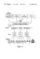
- FIG. 3is a block diagram illustrating preferred embodiments of the present invention.
- FIG. 3Aillustrates communications buses in accordance with preferred embodiments of the present invention
- FIG. 4provides a software/hardware overview of an office communications system in accordance with preferred embodiments of the present invention
- FIG. 5illustrates the use of services/bandwidth allocation rule table(s) in accordance with preferred embodiments of the present invention
- FIG. 6illustrates a general flow chart for controlling incoming and outgoing calls in accordance with preferred embodiments of the present invention
- FIG. 7illustrates an exemplary configuration algorithm for an office attendant type program in accordance with preferred embodiments of the present invention
- FIG. 7Aillustrates an exemplary arrangement of configuration options of the present invention
- FIGS. 8A to 8 Dillustrate exemplary windows in accordance with preferred embodiments of office attendant-type programs in accordance with the present invention
- FIGS. 9A to 9 Cillustrate windows for illustrating additional features/functions in accordance with preferred embodiments of the present invention.
- FIGS. 10A to 10 Billustrate preferred embodiments of the net message windows in accordance with preferred embodiments of the present invention
- FIGS. 11A to 11 Eillustrate various embodiments of the conference windows in accordance with preferred embodiments of the present invention
- FIG. 12illustrates another preferred embodiment of the present invention
- FIGS. 13A to 13 Cillustrate preferred embodiments of video conferencing in accordance with the present invention
- FIG. 14illustrates additional preferred embodiments of the present invention utilizing advanced call logging features
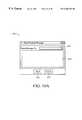
- FIG. 15illustrates a window from a remote administration/configuration application/applet in accordance with preferred embodiments of the present invention
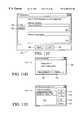
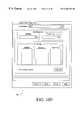
- FIG. 16Aillustrates a preferred exemplary embodiment of a chassis view window in accordance with preferred embodiments of the present invention
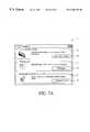
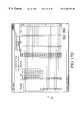
- FIG. 16Billustrates a window for configuration of T-1 channels of a particular communications system in accordance with preferred embodiments of the present invention
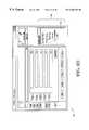
- FIG. 16Cillustrates a window for configuration of station ports of a station card in accordance with preferred embodiments of the present invention
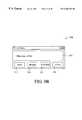
- FIG. 16Dillustrates a window for configuration of analog trunks in accordance with preferred embodiments of the present invention
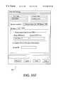
- FIG. 16Eillustrates a window for configuration of frame relay type WAN resources in accordance with preferred embodiments of the present invention
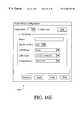
- FIG. 16Fillustrates a window for configuration of network settings in accordance with preferred embodiments of the present invention
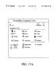
- FIG. 17Aillustrates various icons that may be presented to a remote user to perform remote diagnostics on the communication system in accordance with preferred embodiments of the present invention
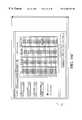
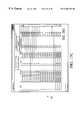
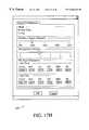
- FIG. 17Billustrates a window for providing a trunk monitoring function in accordance with preferred embodiments of the present invention
- FIG. 17Cillustrates a window for providing a link monitoring function in accordance with preferred embodiments of the present invention
- FIG. 17Dillustrates a window for providing a station monitoring function in accordance with preferred embodiments of the present invention
- FIG. 17Eillustrates a window for displaying trace information from various software components, drivers, etc. in communications systems in accordance with preferred embodiments of the present invention
- FIG. 17Fillustrates a window for providing a first level of tracing information in accordance with preferred embodiments of the present invention
- FIG. 17Gillustrates a window for providing a second, higher level of tracing information in accordance with preferred embodiments of the present invention
- FIG. 17Hillustrates a window for selecting certain timing and mode information in accordance with preferred embodiments of the present invention
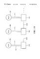
- FIG. 18illustrates a communication system in accordance with another preferred embodiment of the present invention.
- FIG. 19illustrates a communication system in accordance with another preferred embodiment of the present invention.
- FIG. 20illustrates a backup communication module in accordance with preferred embodiments of the present invention.
- FIG. 2provides an overview of such a system in accordance with one preferred embodiment of the present invention.
- Communications system 50provides an integrated system for controlling and managing communications such as in an office. Communications system 50 communicates over ports 26 to file server 20 , printer 22 and one or more computers 24 .
- Ports 26typically includes a packet bus such as Ethernet, “fast” Ethernet, ATM or other LAN technology (in other embodiments, LAN technology, such as token ring, may be coupled to an appropriately configured port).
- Communications system 50includes devices for controlling ports 26 , including controllers such as what are known as a network interface controller (NIC), which may integrate a media access controller (MAC) for control of and interface to ports 26 .
- NICnetwork interface controller
- MACmedia access controller
- Connected to ports 26may be a variety of devices, such as one or more file servers 20 , computers 24 , printers 24 and other computing, peripheral or similar devices suitable for interconnection with ports 26 .
- ports 26is an Ethernet-type LAN to which is connected to a variety of devices as determined by the needs of the particular office/work environment.
- the present inventionprovides effective integration of the packet data LAN and router-type functions with the telephony and server functions, which enables unique operations and the initiation or completion of calls or transactions or the like, without having access to traditional, dedicated devices, peripherals and communications services.
- communications system 50also may implement hardware and software for additional network functions, which are included in alternative embodiments.
- network functionsinclude, but are not limited to: name server, such as DNS (Domain Naming System, which is used in the Internet for translating names of host computers into addresses) or WINS (Windows Internet Name Service, which is a name resolution service that maps or resolves Windows networking computer names to IP addresses particularly in a routed.
- DNSDomain Naming System
- WINSWindows Internet Name Service
- firewallis a hardware/software implement that limits the exposure of a computing system such as communications system 50 or computers coupled thereto to access from a computer external to the system, which may include a network level firewall or packet filter that examines data traffic at the network protocol packet level, or an application-level firewall that examines data traffic at the application level, such as FP or file transfer protocol, email, etc.); proxy server (as is known in the art, a proxy server is a type of firewall that uses a process known as address translation to map internal user IP addresses to the IP address associated with the proxy server firewall in order to provide extra security, etc.); DHCP (Dynamic Host Configuration Protocol, which is a protocol which allows a server to assign dynamically IP addresses to particular computers in real time, etc., which may support manual, automatic and/or dynamic address assignment, which may be used to verify a particular computer's identity, temporarily assign it an IP address for a particular period of time, and reclaim the IP address later for rea
- DHCPDynamic Host Configuration Protocol
- Communications system 50includes the functionality of what is known as a PBX (as will be described further).
- communications system 50is connected to a plurality of telecommunication devices, such as telephones 12 , facsimile 44 and other suitable telecommunications devices and access and server functions (such as private voice mail, recording devices, WAN service interface cards, etc.).
- telecommunication devicessuch as telephones 12 , facsimile 44 and other suitable telecommunications devices and access and server functions (such as private voice mail, recording devices, WAN service interface cards, etc.).
- communications system 50include interfaces for a plurality of telecommunications devices for the particular and complete office/work environment and infrastructure.
- Communications system 50is coupled to WAN voice/data services network(s) 58 through trunks 54 .
- Voice/data services network(s)may include private line, local or long distance carrier networks, Internet, intranet and/or any other current or future WAN-type network services.
- Trunks 54may consist of high, medium or low speed digital and/or analog lines, either public or private, and in certain preferred embodiments consist of high speed dedicated resources such as what are known as T-1, PRI (Priary Rate ISDN), ATM, VDSL, HDSL, ADSL, wireless, cascade, proprietary and/or twisted pair analog lines from a local telephone company.
- communications system 50is coupled to WAN services, trunks and the like in a manner that the user, service provider, administrator and/or algorithm has determined will provide adequate or required resources, on a cost-effective basis, for the particular office/work environment and operating conditions.
- the communications system of FIG. 2provides an integrated solution for voice and data communication services, to which may be connected the WAN network services and telecommunications, computing and other devices as determined by the particular office/work environment.
- Communications system 50is controlled by host processor/system resources 70 , which in preferred embodiments include a computer powered, for example, by a commercially available or other microprocessor and an embedded and/or commercially available operating system. What is important is that processor/system resources 70 provide sufficient processing power, memory and storage resources (RAM, ROM, hard disk, magnetic or other storage, etc.), bus and other resources in order to control the various subsystems and components as will be described. In particular, computer/system resources 70 enables automatic internal negotiation, control and enabling of services and applications. Although not expressly shown, processor/system resources 70 also may include other components of a relatively high-end personal computer, workstation or server, such as a display device, keyboard, serial ports, parallel ports, power supply and the like.
- processor/system resources 70also may include other components of a relatively high-end personal computer, workstation or server, such as a display device, keyboard, serial ports, parallel ports, power supply and the like.
- processor/system resources 70provide system and server management software and the like, and a platform for various server applications as described herein Host processor/system resources 70 is coupled to buffer/framer 72 via bus 84 , which in preferred embodiments consists of a computer bus such as what are known as a PCI bus or ISA bus (in other embodiments, other suitable computer-type buses are utilized, which may include is proprietary local buses).
- bus 84which in preferred embodiments consists of a computer bus such as what are known as a PCI bus or ISA bus (in other embodiments, other suitable computer-type buses are utilized, which may include is proprietary local buses).
- Buffer/framer 72includes buffer 71 and preferably includes a plurality of multi-protocol framing/deframing engines, such as for what are known as asynchronous transfer mode (ATM) or high-level data link control (HDLC) protocols, which may be synchronous or asynchronous. In other embodiments, other communication protocol framers/deframers are provided, as may be desired by the particular office/work environment.
- Buffer/framer 72in certain preferred embodiments includes, for example, one or more ATM framers/deframers 73 A and one or more, and preferably a plurality of, HDLC framers/deframers 73 B.
- buffer/framer 72includes other controlling circuits (such as a slot mapping memory, multiplexers/demultiplexers, arbitration, control and other circuitry) such as, for example, described in U.S. Pat. No. 5,533,018 to DeJager, et al. for “MULTI-PROTOCOL PACKET FRAMING OVER AN ISOCHRONOUS NETWORK,” which is hereby incorporated by reference.
- buffer/framer 72includes the capability to transfer raw or protocol-processed data, which may be mapped to particular slots of TDM bus 78 and made available on different ports.
- Buffer/framer 72is controlled by processor/system resources 70 as diagrammatically indicated by control line(s) 92 (control line(s) 92 may be implemented as part of a bus structure, such as bus 84 ).
- processor/system resources 70includes redundant disk or other storage, redundant power supplies and data back-up to magnetic or other media in order to enhance fault tolerance of the system.
- DSP 76preferably consists of a single digital signal processor or multi-digital signal processor resource pool, which serves to provide a variety of functions within communications system 50 .
- DSP 76generates dial tones (such as for telephones 12 ), and also performs DTMF digit detection and decoding, echo cancellation, coding/decoding functions, voice conferencing, voice compression, voice recognition and the like.
- DSP 76performs data compression, transcoding, processing for voice communications using an Internet protocol (“IP”) or other voice over other network protocol or the like.
- IPInternet protocol
- DSP 76provides a set of processing and memory resources to support the various voice/data services controlled and managed by processor/resources 70 . As illustrated by bus connection 84 A, DSP 76 alternatively may be coupled directly to TDM bus 78 .
- Switch/multiplexer 74communicates bidirectionally with buffer/framer 72 and preferably with DSP 76 , as illustrated, over bus 86 .
- Switch/multiplexer 74also communicates with TDM bus 78 , as illustrated, over bus 90 .
- TDM bus 78preferably is a time division multiplexed bus as is known in the art (such as, for example, what is known as an MVIP or multi-vendor integration protocol type bus, or what is known as an SCSA-type bus (SCSA is an acronym for Signal Computing System Architecture)), and provides in certain preferred embodiments 256 channels/slots per TDM frame (the present invention is not limited to a single TDM bus; in alternative embodiments, more than one TDM bus or other types of TDM buses are utilized).
- TDM bus 78allows communication between devices on the bus by way of circuit switching techniques. This type of switching allows for simple and inexpensive communication of voice through, for example, what are known as pulse code modulation (“PCM”) techniques.
- Switch/multiplexer 74preferably is implemented with one or more switching/serial time division multiplexing circuits, such as, for example, described in U.S. Pat. No. 5,541,921 to Swenson, et al. for “ISOCHRONOUS SERIAL TIME DIVISION MULTIPLEXER,” which is hereby incorporated by reference.
- Switch/multiplexer 74under control of processor/system resources 70 , provides the capability for various voice/data signals to be controllably switched to desired slots of TDM bus 78 .
- Coupled to TDM bus 78are line, station, trunk, or other interface cards 82 .
- Cards 82provide CODEC, line interface, off-hook detect and other functions as are known in the art to support various telecommunication devices (such as telephones 12 and facsimile 44 ) and WAN-type network services (such as voice/data services 58 ) that are communicating with communications system 50 via TDM bus 78 .
- cards 82provide points of termination for a plurality of telephones 12 , one or more facsimiles 44 , and various T-1, PRI, ATM, analog and/or other WAN-type network services as determined by the particular office/work environment.
- Cards 82under control of processor/system resources 70 , may include points of termination for emergency or backup telephone services and the like, such as in the event of a power failure or to provide analog services in the event a dedicated resource such as a T-1 is unavailable for some reason.
- Communication system 50also may include fax modem 75 , which, under control of processor/system resources 70 , may process incoming/outgoing facsimile transmissions.
- fax modem 75is coupled to TDM bus 78 as illustrated, although in other embodiments fax modem 75 may be coupled in alternative arrangements, such as to switch/multiplexer 74 and/or DSP 76 .
- Communication system 50also may include available card slots on TDM bus 78 for one or more module upgrades 77 . Additional resources and/or functionality may be added to communication system 50 as needed by way of module or line card upgrade(s) 77 , or by, for example, the addition of one more cards such as ATM controller 79 B and DSP 79 C. Through the use of such module upgrades or additional cards, etc., one or more minimal configurations of communication system 50 may be provided, with additional resources and/or functionality added by the insertion of additional cards to TDM bus 78 . In accordance with preferred embodiments of the present invention, software upgrades for processor/system resources 70 , or for other resources in the communications system, also may be applied.
- Processor/system resources 70also is coupled to one or more packet buses, such as packet buses 80 A and 80 B, which may be through a bus such as LAN bus 81 .
- packet buses 80 A and 80 Bprovide multiple hubs or switches to intercommunicate between one or more packet networks, which in preferred embodiments are Ethernet networks.
- the bus configuration of FIG. 3may be considered “logical”, and in preferred embodiments the physical bus configuration may be such that TDM bus 78 and packet buses 80 A and/or 80 B are part of the same physical bus.
- packet buses 80 A and/or 80 Balso can intercommunicate directly with central resources (such as processor/system resources 70 ) as well as station cards and WAN cards (or any other cards) coupled to the TDM bus (this is illustrated in FIG. 3 by card 79 D, which is a card simultaneously inserted into/coupled to both TDM bus 78 and packet bus 80 A and which may comprise, for example, a combined LAN interface/functionality and central office (or other WAN interface) card.
- card 79 Dis a card simultaneously inserted into/coupled to both TDM bus 78 and packet bus 80 A and which may comprise, for example, a combined LAN interface/functionality and central office (or other WAN interface) card.
- Such a combined interface cardwhich may support both LAN and WAN functions (such as described elsewhere herein), enables substantial advantages over conventional systems.
- Coupled to packet buses 80 A and/or 80 Bare a variety of computing-type devices, such as computers 24 , printer 22 , other computers, file servers, backup or storage resources, other networks and the like.
- Processor/system resources 70in software and/or hardware, provides a LAN/network subsystem, which includes routing and other related functions to support data communications to and from packet buses 80 A and/or 80 B and TDM bus 78 , etc., through several paths or methods.
- a more direct connection between packet bus 80 A and/or 80 Bmay be established by way of embedded router or bridge 83 .
- Router/bridge 83includes a CPU, TCP/IP controller, router, stack, Ethernet interface or other functionality as may be desired to couple LAN bus 81 to, for example, one or more HDLC controllers 79 A.
- communications between packet buses 80 A and 80 Bmay be accomplished while consuming minimal resources of processor/system resources 70 .
- FIG. 3Aadditional aspects of preferred embodiments of the present invention will now be described.
- communications system 50includes at least three (3) separate types of busses, e.g., TDM bus 78 , packet bus 80 A (or 80 B), etc., and control bus 92 , etc.
- bussese.g., TDM bus 78 , packet bus 80 A (or 80 B), etc., and control bus 92 , etc.
- preferred embodiments of the present inventionutilize an arrangement that desirably configures such busses into a passive backplane that may be used to plug in various printed circuit boards, cards, etc.
- Bus 408is provided, for example, to serve as a bus for a computer backplane, such as a personal or other computer included in processor/system resources 70 (e.g., a computer system bus, such as what are known as PCI or ISA buses, etc.).
- processor/system resources 70e.g., a computer system bus, such as what are known as PCI or ISA buses, etc.
- Various boards or cards, etc. 400 A, 400 B and 400 Cmay be physically plugged into sockets 402 and 404 .
- Sockets 402are provided for making electrical connection to bus 408
- sockets 404are provided for making electrical connection to bus 406 .
- sockets 402 and 404are provided, with at least certain of sockets 402 being positioned adjacent to and aligned with sockets 404 .
- boardssuch as board 400 A may be coupled to bus 406 through one of sockets 404
- board 400 Bmay be coupled to both bus 406 and bus 408 via one each of sockets 404 and 402
- board 400 Cmay be coupled to bus 408 through one of sockets 402 .
- bus 406which includes control bus 92 , packet bus 80 A, and TDM bus 78 , may be coupled to boards that couple only to bus 406 and also boards that couple to both bus 406 and bus 408 .
- a plurality of sockets and boardsmay be provided, with one or a plurality of boards similar to board 400 A, one or a plurality of boards similar to board 400 B, and/or one or a plurality of boards similar to board 400 C may be desirably provided in communications system 50 .
- bus 92is similar in form to a standard ISA or PCI bus (although preferably modified/optimized for the particular implementation of communications system 50 ) and provides desired control to the various components and subsystems of communications system 50 (as described elsewhere herein).
- TDM bus 50may consist of, for example, 256 channels at 64K bits/second.
- Packet bus 80 Amay support one or a plurality (e.g., 3, 4, 5 or more) of ethernet or other packet buses, such as 100M bit, full duplex ethernet capability or similar functionality (although only one such bus in illustrated in FIG. 3 A).
- boardsmay be conveniently coupled to bus 406 and/or 408 , which facilitates manufacture, upgrade, maintenance, etc. of communications system 50 .
- bus 408may be, for example, an industry standard bus, such an ISA or PCI or similar bus, thereby enabling ready connection of available PC-type boards to communications system 50 if so desired for the particular application.
- Such a multi-backplane constructionprovides significant advantages in accordance with the present invention.
- FIG. 4provides a software/hardware overview of an office communications system in accordance with preferred embodiments of the present invention. It should be noted that the preferred embodiment of FIG. 3, with appropriate software in processor/system resources 70 , may provide the software/hardware described in connection with FIG. 4, as will be appreciated by those skilled in the art.
- LCRleast cost routing
- BQOSbest quality of service
- B/Wbandwidth
- LCR, BQOS and B/W rules 21provide tables, information, rules and/or algorithms by which data and voice communications may be allocated and/or controlled with respect to, for example, the various types of voice/data network services that are available to communications system 50 .
- Such informationmay include the current cost of utilizing various resources (based on time of date, amount of usage, integrated amount of usage over some period of time, etc.), and also priority rules for the various types of communications provided by communications system 50 .
- phone callsmay be assigned a priority 1, facsimile calls a priority 2, VoIP calls a priority 3, facsimile over IP calls a priority 4, category 1 data communications a priority 5, and other data communications a priority 6.
- the priority assignmentsmay change by time of day or month, and/or the priority assignments may be different with respect to different network resources and the like.
- Server encryption applications 23may be provided in order to provide encryption or similar coding or processing of voice/data communications processed by communications system 50 .
- VoIP gatekeeper 25may be provided to service and control voice over Internet protocol (“VoIP”) communications.
- VoIPvoice over Internet protocol
- various types of VoIP communicationsmay be effectively managed and controlled in accordance with preferred embodiments of the present invention, such as, for example, a determination that acceptable conditions exist on the Internet for such communications.
- Directory 27may be provided in order to make various types of directory information available to users of communications system 50 .
- Directory information provided by directory 27may include names, telephone extensions, address or other personal or work information regarding persons or departments, etc., serviced by communications system 50 .
- Directory 27also may include similar directory type information for persons or departments, etc. in a remote or other locations, such as may be accessed through voice/data services 58 .
- Intelligent/dynamic B/W, service and resource management 31is provided to effectively and efficiently control and allocate and de-allocate services and communications resources, such as in accordance with LCR, BQOS, BIW rules 21 (e.g., rules to enable lowest cost, highest quality or otherwise desirable management and control of network or other resources, etc.) or other applications 29 or the like.
- B/W management 31also receives as inputs information indicating the total number and types of network resources (of voice/data services 58 , for example) that are available to communications system 50 , and their status and availability at any given point in time.
- B/W management 31may receive as an input, or may generate internally, information indicating how much of a measured usage resource may be available at a given point in time (for example, “fame relay,” “private virtual channel” or other network services may be provided on the basis of a predetermined amount of data transmission per fixed time period for a fixed price, with additional charges for usage in excess of the predetermined amount, etc.). As more fully described below, based on the currently available and currently utilized services and resources, B/W management 31 may allocate and de-allocate such services and resources in a desired and/or cost efficient manner.
- Services 37which may be supported by database storage 35 (which may be provided as a part of processor/system resources 70 ), include data switching services, router services and PBX station services.
- database storage 35which may be provided as a part of processor/system resources 70
- PBX station servicesinclude data switching services, router services and PBX station services.
- various communication-related servicesmay be advantageously supplied by communications system 50 .
- data switching servicesmay be provided such as by LAN/NDIS/DDI drivers 39 (LAN, NDIS and DDI being exemplary) through hardware modules such as switched Ethernet 45 and hub 47 .
- Routing servicesmay be provided such as through WAN drivers (specific network services such as PRI and T-1 being exemplary) through hardware modules such as T-1 module(s) 49 , ISDN module(s) 51 , central office-plain old telephone service (CO-POTS) module(s) 53 , V.35 module(s) (it should be understood that various hardware modules may be utilized in accordance with preferred embodiments of the present invention, as desired to implement the various data switching, routing and other communications connections as may be determined by the needs of the particular office/work environment.
- PBX station servicessuch as automated attendant, reception, voice mail and the like, may be provided through station manager 43 .
- Station manager 43provides hardware for connection to various telecommunications devices, such as phones 12 , facsimile 44 , etc. In general, station manager 43 provides sufficient interface hardware in order to connect to the various devices that may be determined by the needs of the particular office/work environment).
- FIG. 5a general flow chart will be described for illustrating the use of services/bandwidth allocation rules in accordance with preferred embodiments of the present invention.
- Server applicationssuch LCR, BQOS, BIW rules 21 , may be considered to have various rule sets, such as voice rules 93 , data rules 95 and dial-up rules 97 (other rule sets may be provided).
- Communications system 50monitors inputs (illustrated as monitor inputs block 91 of FIG. 5 ), and based on such inputs and the overall service/network resources available, and in accordance with voice rules 93 , data rules 95 and dial-up rules 97 , allocates and de-allocates resources (illustrated as allocate/re-allocate resources block 99 of FIG. 5 ).
- processor/system resources 70controls switch/multiplexer 74 to couple the appropriate card 82 to DSP 76 , which generates a dial tone that is coupled to the appropriate telephone 12 . The user hears the dial tone and may then proceed to place the desired call.
- DSP 76detects the digits of the telephone number of the desired call and provides the detected digits to processor/system resources 70 .
- processor/system resources 70directs that the called internal telephone receive a ring signal from the appropriate card 82 .
- TDM bus 78and the appropriate cards 82 .
- processor/system resources 70attempts to establish the desired connection through the appropriate cards 82 and available voice/data services 58 .
- processor/system resourcespreferably follows the general flow illustrated in FIG. 5 . Namely, in accordance with available resources (such as of voice/data services 58 ) and rules such as voice rules 93 , data rules 95 , dial-up rules 97 , etc., an external voice communication may be established by, for example, a POTS line connection, an ISDN B channel, a VoIP connection, etc.
- resourcesmay be allocated for the processing of such an external call based on the available resources at the particular time and applicable rules (which may include time of day, priority of call, etc.)
- Incoming callsare detected by the appropriate cards 82 and signaled to processor/system resources 70 . Connections of voice incoming calls to telephones 12 are established under control of processor/system resources 70 over TDM bus 78 .
- FIG. 2With the hardware of preferred embodiments as illustrated in FIG. 3, various novel and/or improved or more efficient communications functions may be obtained.
- a plurality of workstations or computers 24may be connected to communications system 50 .
- two or more LANsmay be coupled to communications system 50 , with a plurality of computers coupled to each of the two or more LANs, etc.
- one or more of computers 24may execute a PBX/telephony control application software program.
- PBX/telephony control applicationhereinafter referred to as the “office attendant type” program
- control of the telephony and related functions of communications system 50may be intelligently managed and controlled.
- one or more computers on the LANmay be used to control incoming and outgoing calls of the office using the computer in a natural and intuitive manner.
- a telephony headset or telephonepreferably is associated with the particular computer that will be running the office attendant type program to enable traditional voice communications with incoming callers, etc.
- a party desiring to control the incoming and outgoing calls and/or station to station calls of the office(“attendant 1”) may log-on and run the office attendant type program from one of the computers connected to the LAN connected to communications system 50 .
- attendant 1may be required to enter an appropriate user name/ID and password in order to recognize attendant 1 as an appropriate user to assume control of the telephony functions of the office.
- a network or systems administratormay set up password control for parties authorized to run the office attendant type program.
- the computer running office attendant type programhas downloaded to it the current telephone subscriber directory such as over packet bus 80 A or 80 B of FIG.
- communications system 50automatically determines when subscriber information changes, e.g., a subscriber has been added to or deleted from the telephone directory, or an extension has changed, or a subscriber's status information has changed, or any state associated with communications system 50 , etc., in order that updates may be timely made available.
- computers running the office attendant type programmay be updated promptly and automatically by communications system 50 so as to contain current subscriber information on an ongoing basis to more efficiently control telephony operations of the office.
- the subscriber informationalso may include other information, such as the email address and extended directory information including personal information manager (“PIM”) information of the particular subscriber and network identification for a computer associated with the particular subscriber. With such information, net messages or other communications with particular subscribers may be facilitated as more fully described herein.
- PIMpersonal information manager
- communications system 50includes information regarding all users registered in the PBX (i.e., all users having a telephone extension and/or computer coupled to communications system 50 such as over the LAN or WAN).
- communications system 50may “broadcast” updated subscriber directory information to all computers coupled to communications system 50 , or, in alternate embodiments, communications system 50 sends a net message, email or other message to such computers coupled to communications system 50 that prompts the users of such computers to the availability of the subscriber directory update (e.g., the remote computers receive a message indicting the availability of the subscriber directory update, which preferably includes an “accept” icon and a “reject” icon, thereby enabling the user to receive or not receive the update as he/she may desire).
- the remote computersreceive a message indicting the availability of the subscriber directory update, which preferably includes an “accept” icon and a “reject” icon, thereby enabling the user to receive or not receive the update as he/she may desire).
- This conceptmay be extended to system speed dial buttons (as described elsewhere herein), and other information that may be desirably controlled and distributed in/from a central location (e.g., conimunications system 50 ) in a particular office setting.
- a central locatione.g., conimunications system 50
- a company organization chart, financial reports, informational reports, etc.may be centrally stored, etc., which may include being maintained by a system administrator-type person for communications system 50 .
- centrally-controlled informationmay be broadcast to all users, or a selected subset of such users (communications system 50 also preferably accesses/stores information regarding the registered users, such as title, department, position within the company; e.g., Vice President, engineering department, sales and marketing department, etc.).
- a centrally-maintained document/filesuch as a company organization chart, financial report, etc.
- communications system 50records which computers receive such information (for example, a record of those computers logged-on and receiving the information at the time it is first distributed), and thereafter may distribute the information to other computers at a later time (for example, at a later time when the users of such computers log-on to communications system 50 ).
- Such embodimentsalso may prompt the individual users whether they wish to receive the information, and thereafter provide the information to those computers whose users affirmatively indicate that they desire to receive the information.
- the computer running the office attendant type programoptionally may run a configuration routine to more optimally configure the office attendant type program on the particular computer for control of the telephony operations.
- the computer running the office attendant type programis in a ready condition for processing incoming or outgoing calls or the like.
- FIG. 7illustrates options such as password change option 112 , contact or personal information manager (“PIM”) import option 114 , user interface configuration option 116 and other option 118 (other option 118 indicates other configuration options that may be presented to the user to more optimally configure the office attendant-type program for the particular user or operating environment, etc).
- PIMpersonal information manager
- the computer running the office attendant type programhas completed the configuration process and is in a ready condition for processing incoming or outgoing calls or the like.
- configuration window 111An exemplary arrangement of configuration options for such a configuration algorithm is illustrated in FIG. 7 A.
- configuration window 111a user may be presented with configuration windows such as user interface configuration window 113 , contact or PIM import window 117 or password control window 121 .
- user interface window 113may include icon 115 for displaying menus or windows for tailoring the user interface for the particular user and operational parameters; exemplary user interface options include user selectable tones, sounds, or volumes for indicate incoming calls, line status conditions, programmable call capacity before routing calls to another computer running an office attendant-type program or to an automated call answering algorithm of communications system 50 , visual display options to vary the computer display (such as size, color of icons or background, etc.) of the screens of the particular office attendant type program, etc.
- What is importantis that a particular user running an office attendant-type program on a particular computer may configure user interface-type attributes to more optimally configure the computer that the user will use to control the incoming and outgoing calls of the office, etc.
- each such computerin preferred embodiments may be independently configured to be more optimum for the particular computer users.
- PIM import window 117may include icon 119 for displaying menus or windows for importing contact information from a PIM-type software program or database.
- contact information to be used by the user running the office attendant type programmay be readily imported from a PIM-type information database or contact list (which may be resident on the particular computer, in communications system 50 or on another computer coupled to a LAN), thus saving the time from entering contacts from a manual or electronic list.
- Password control window 121may include icon 123 for displaying menus or windows for enabling the user to change his/her password.
- the office attendant-type program(s) used to control telephony functions of communications system 50utilizes password protection to prevent database tampering and the like and also to prevent unauthorized use of the office attendant-type program(s).
- window 130includes one or more line displays 132 (five are shown in FIG. 8A for illustrative purposes) for indicating various telephone lines available in the particular application of communications system 50 .
- the number of telephone linesmay be tailored for the particular application.
- call/line status display 148Preferably positioned adjacent to line displays 132 is call/line status display 148 for displaying symbols adjacent to each line indicative of the status of the line, such as idle, phone ringing, active call in progress, call on hold, hold recall alert, etc.
- Status display 148provides a ready visual indicator to the user of the office attendant-type program of the status of the various telephone lines that are being monitored. Also adjacent to the line displays (as illustrated adjacent to status display 148 ) are user identification displays 150 , which serve to display the name and/or extension or telephone number of one or both parties to a call. In certain embodiments, caller ID type information may be obtained by communications system 50 from an appropriate interface card (see interface cards 82 of FIG. 3) and also displayed on displays 150 . Displays 150 also may display a clock indicating the duration of a call on a particular line.
- window 130also includes calling feature buttons or icons such as dialpad icon 134 , feature icon 136 , system icon 138 and/or contacts icon 140 .
- Other iconsmay include call log icon 142 and/or configuration icon 144 .
- Dialpad icon 134preferably results in the display of a dialpad, such as dialpad window 165 in the lower left comer of window 130 .
- Feature icon 136preferably results in the display of a set of feature buttons as will be described in connection with FIG. 8 B.
- System icon 138preferably results in the display of a set of system buttons as will be described in connection with FIG. 8 C.
- Contact icon 140preferably results in the display of a list of contacts/contact folders as will be described in connection with FIG. 8 D.
- Call log icon 142preferably results in the display of one or more windows displaying log-type information for incoming or outgoing calls controlled by the office attendant type program. Call log information may be retained on the particular computer running the office attendant type program and/or centrally stored by communications system 50 .
- Configuration icon 144prompts one or more configuration windows, examples of which have been described elsewhere herein.
- Help icon 146also may be provided in order to display help information to the user of the office attendant-type program.
- hold icon 180is provided to enable a caller to be readily put on hold by the office attendant type program user.
- Transfer icon 178is provided to enable a caller to be readily transferred by the office attendant type program user (transfer operations are discussed in more detail in connection with FIGS. 9 A through 9 C).
- Hangup icon 176is provided to enable a caller to be readily disconnected by the office attendant type program user.
- Net message icon 174is provided to enable a net message to be sent by the office attendant type program user (net messages are discussed in more detail in connection with FIGS. 10 A and 10 B).
- Conference icon 172is provided to enable conferences to be established by the office attendant type program user (conferences are discussed in more detail in connection with FIGS. 11 A through 11 E).
- Answer next icon 170is provided to enable the office attendant type program user to sequentially answer calls, such as, for example, in a situation in which numerous calls have come in a short period of time, and the user wishes to sequentially access such calls.
- the answer next iconprioritizes calls on hold higher than new calls, although in preferred embodiments the priority of hold calls versus new calls may be programmed into communications system 50 .
- Dialpad window 165accessed in response to activation of dialpad icon 134 , displays a visual keypad, much like a traditional telephony keypad with buttons 164 , and also preferably includes other buttons such as call button 168 (for initiating calls), clear button 166 (for clearing number or information, such as subscriber information, displayed on display 162 (display 162 also may used to input numeric or character information such as for a subscriber, and also may have a menu pulldown icon as illustrated to display a menu of, for example, subscriber information), personal button 156 (which may be used, for example, to make personal contact or PIM information available in display 162 ), system button 160 (which may be used, for example, to make system contact information available in display 162 ), or both button 158 (which may be used, for example, to make both personal contact or PIM information and system contact information available in display 162 ).
- call button 168for initiating calls
- clear button 166for clearing number or information, such as subscriber information, displayed on display 162
- Feature box 184includes one or more configurable feature buttons 186 .
- Such feature buttonsenable a configurable environment for the office attendant type program user, by enabling particular tasks to be configured for particular feature buttons.
- task/featuresmay include dialing particular calls, forwarding calls to another extension, transferring calls to another extension, unforwarding calls, setting do not disturb for particular extensions, dialing international or special toll calls or the like, or other tasks that a particular user may find desirable to have accessible with a single or very few clicks of the computer mouse or pointer.
- the particular feature buttonspreferably include textual information descriptive of the particular feature or task associated with the displayed button. In preferred embodiments, feature buttons may be added or deleted as desired by the particular user.
- system box 190includes a plurality of system buttons 192 , which provide essential contacts, such as emergency numbers (e.g., police or fire or building security), the numbers particular to departments or officers in the particular company, branch office numbers, etc.
- system box 190a user may have readily displayed the numbers of essential or important contacts, which may be connected with a single click of the computer mouse or pointer.
- the numbers or contacts associated with particular system buttonsmay be programmed by the user, but more preferably are programmed by the administrator of communications system 50 and downloaded in a manner similar to the subscriber information as previously described.
- contacts box 196preferably includes a directory of contacts for the company of the user (illustrated generally as folder and contact tree 198 ), and also preferably contact or PIM-type information that may be obtained by importing from a PIM-type program or database resident in communications system 50 or on one or more of the computers coupled to communications system 50 .
- contact informationmay be quickly provided to the office attendant type program user with a single or very few clicks of the computer mouse or pointer.
- caller ID informationis available to communications system 50 , which may be made available to the office attendant-type program.
- the office attendant-type program or a companion programmay associate a contact with the caller ID information, and thereafter display contact information to the user.
- callsmay be directed to the computer running the office attendant type program because a main number has been directed to this computer (and its associated telephone or headset), or because calls have been forwarded to the office attendant type program, or because a called party is on the phone, has indicated the called extension is “do not disturb,” etc.
- the office attendant type program usermay need to transfer calls to other extensions, either inside the office or outside the office.
- persons in the officehave a computer running a program in companion with the office attendant-type program.
- windowsmay include, for example, an animated icon, caller ID information, etc., and may include one or more icons the clicking of which causes the call to be answered.
- the office attendant type programmay cause one or more windows to appear on the computers of particular persons in the office, such as a person to whom a call is being directed.
- a callmay come in through WAN services network 58 (see, e.g., FIG.
- a main telephone numberwhich may be designated to be forwarded to a telephone associated with a person running the office attendant type program on a particular computer 24 , and may be so directed by way of TDM bus 78 and switch/multiplexer 74 , under control of processor/system resources 70 .
- the computer 24 running the office attendant type programmay be used to transfer the incoming call to a particular extension, which may be readily accomplished by way of transfer icon 178 (see FIG. 8 A).
- FIG. 9Aillustrates window 200 , which may provide a list of subscribers and extensions 202 .
- the transfermay be readily completed with a simple click of the mouse or pointer on transfer icon 204 .
- the transfer operationmay be canceled by a click of the mouse or pointer on cancel icon 206 . It should be noted that, because the current subscriber information has been downloaded by communications systems 50 (as described elsewhere herein), more reliable transfer of calls may be achieved in accordance with the present invention.
- a windowin the event of a failed transfer, for example in case the extension to which the call is being transferred is busy, a window preferably is automatically displayed on the computer running the office attendant type program.
- An exemplary window 208is illustrated in FIG. 9 B.
- display 210may display a descriptive message, such as “line busy,” “do not disturb,” etc.
- a number of iconsalso are simultaneously displayed to aid the office attendant type program user in processing this call.
- Hold icon 212may be used to place the caller on hold.
- Message icon 214may be used to initiate a net message to the party to whom the call is to be transferred.
- Voice mail icon 216may be used to direct the call into the voice mail of the party to whom the call was to be transferred.
- Cancel icon 218may be used to cancel the transfer operation.
- activation of hold icon 212automatically “parks” the call on the extension of the party to whom the call is to be transferred
- particular subscribersmay have the option to program their extension so that calls parked on their extension may or may not be automatically connected once the called party has completed its current call.
- the office attendant type programmay be configured to automatically send a message (over a packet bus, as described earlier) to the computer of the party to whom the call is to be transferred, such as is illustrated by window 220 in FIG. 9 C.
- window 220may contain message box 222 , which may contain a message such as “call holding” or “call holding from Mike at extension 226 ,” or “call holding; outside caller, number xxx,” etc. What is important is that message box 222 display a message that a call is holding, with appropriate information identifying the caller displayed to the extent possible or desired. It should be noted that in certain embodiments caller ID information is displayed, and in some such embodiments a directory or library of names or other identifying information may be contained in communications system 50 and/or one or more of the computers connected to the LAN so that names or other identifying information may be associated with the caller ID information and displayed in message box 222 . Preferably, the computer of the called party plays an audible tone or sound
- the called partymay decide to terminate his/her existing call and accept the call from the party being transferred, such as by clicking on accept icon 224 .
- the called partymay decide to have the call from the party being transferred wait, such as by clicking on wait icon 226 .
- the particular user being calledpreferably has the option to configure his extension to accept parked calls or to not accept parked calls.
- the particular useralso preferably has the option to select an allowed parking time before the call is returned to the user running the office attendant type program.
- a transferred callmay be temporarily parked, with an appropriate message displayed on the computer of the called party, with the parked call either accepted by the called party clicking on accept icon 224 , returned to the user running the office attendant type program or forwarded to voice mail after a parking time out time has elapsed, or the call held longer than the allowed parking time by the called party clicking on wait icon 226 .
- clicking on wait icon 226enables the call to be parked indefinitely, while in other embodiments a second, longer and preferably user configurable parking time is enabled (thus preventing a called from being held for an indefinite period of time).
- the callis returned to the user running the office attendant type program or forwarded to voice mail, and still preferably an audible tone or sound is periodically emanated from the computer of the called party while the call is parked, thereby providing a subtle reminder of the existence of the parked call.
- usershave the ability to mute or lower the volume of the reminder sound, such as by way of an additional icon in window 220 .
- usershave the ability to configure and select the particular options described herein that the particular users may desire.
- a window 208may be displayed in response to a transferred call being returned to the use running the office attendant type program, or it or a similar window may be displayed in response to the user running the office attendant type program “looking ahead” to the status of the extension to which the call is to be transferred. What is important is that the user running the office attendant type program determine that the transfer may not be accomplished, and then optimally be provided with options for processing the call in an expedient manner, such as described elsewhere herein.
- a window such as window 220 of FIG. 9Cmay be displayed on the computer of the called party, either automatically for all calls, or only in the event that the called party has put his telephone on do not disturb, but has configured his extension to receive a message notification of calls, or in the event that the called party is on the line.
- communications system 50may generate such a window by a suitable message sent over by packet bus to the user's computer.
- communications system 50may simultaneously ring a user's extension and notify the user of the call with a net message, with the call being accepted, parked or forwarded to voice mail such as described earlier.
- communications system 50preferably takes the programmed action directly.
- a usermay configure his extension so as to route all calls to another extension or to a local or long distance telephone number.
- Such a useralso may configure his extension so as to route all calls as voice over IP (“VoIP”) calls.
- VoIPvoice over IP
- processor/system resources 70 and/or DSP 76may process the incoming voice information (received through the appropriate station card 82 and via TDM bus 78 , etc.) into appropriate IP packets, which may then be routed, for example, through an HDLC framer/deframer 73 B, through switch/multiplexer 74 , over TDM bus 78 and out over a designated IP connection via WAN services 58 , etc.
- FIG. 10Aillustrates window 230 as an exemplary net message window that may be generated in response to clicking icon 174 or 214 .
- window 230preferably includes box 232 to identify the recipient of the intended net message, which may be automatically selected by the office attendant type program in the event of a failed call transfer situation.
- the recipientmay be selected by pull-down menu as illustrated, or by direct entry of a name or extension number, etc.
- the office attendant type programautomatically scrolls through the subscriber directory in order to more quickly arrive at the desired net message recipient.
- Box 234is provided in order for the office attendant type program user to type a desired net message.
- a list of pre-generated net messagesare available via a pull down menu or window opened with an icon or the like (such pre-generated messages may include whole or partial messages, greetings, etc. that are frequency utilized, thereby saving the user from having to type a repetitive message, etc.).
- the net messagemay be sent by clicking on send icon 236 or canceled by clicking on cancel icon 238 .
- the net message recipientmay be a user physically located in the same office and receive the net message by way of packet bus 80 A or 80 B (see FIG.
- the net messagemay be sent as Internet or other message by way of TCP/IP through modem 75 or through the WAN services network 58 (e.g., a T1 connection) by passing through an HDLC framer 73 B, such as was described with reference to FIG. 3 .
- TCP/IPTransmission Control Protocol/IP
- modem 75or through the WAN services network 58 (e.g., a T1 connection)
- HDLC framer 73 Be.g., a T1 connection
- callsmay be forwarded off-premises (by appropriate programming of the particular user's extension, as described elsewhere herein), and net messages likewise may be forwarded off-premises.
- FIG. 10Billustrates net message window 240 that may appear on the computer of the recipient.
- the recipientis presented with the net message in window 242 , and may close the net message by clicking icon 244 .
- net messagesmay be stored for archival purposes or later viewing, and in alternative embodiments net messages also include a reply icon which may be clicked in order to bring up a window in which a reply message may be typed.
- an office attendant type program usermay inform the recipient, for example, of a particular caller, and the recipient may inform the office attendant type program user, for example, that the caller should be directed to a particular individual or department or processed in a particular way (directly to voice mail, call terminated, etc.).
- packet bus or other messagesmay be readily exchanged in a manner to more readily facilitate telephony management etc.
- net messagesmay be sent from a computer running an office attendant-type program or a companion program, to any other computer coupled to communications system 50 , either by way of the LAN or WAN, etc.
- the net messagemay be sent (preferably via communications system 50 ) either as a net message as previously described, or in the form of a visual “pink slip,” “yellow sticky note,” etc., which preferably appears in a small window on the screen of the user/message recipient
- such “pink slip” or “yellow sticky note” messagesinclude icons for options such as reply, delete, file/store, minimize, etc.; preferably, after a reply, delete, and/or file/store command, the message window automatically disappears.
- such messagesautomatically stack up, with a visual representation of stacked messages presented to the user (e.g., showing a third dimension of a stack of messages, etc.).
- the userpreferably sees the most recently received message on top, and also has the option to freeze/hold the updating of the message stack such as by selecting a suitable icon (e.g., if the user is reading a particular message, he/she may command that the message being read is not replaced by a subsequently received message), scroll through the stack of messages, etc.
- communications system 50automatically stores and sends as email all such messages that are not processed in a definitive manner by the user (e.g., if the user logs off without having replied, deleted, stored, etc. such messages, then communications system 50 processes such unclosed messages as emails to the particular user or users, etc.).
- a sender of a net messagemay be prompted that a particular user to whom a net message is being directed is not logged on. In such embodiments, the sender may then be prompted (such as with a suitable information display and icon) to convert the net message to an email message, etc.
- conference icon 172may be utilized to initiate a conference call in accordance with certain preferred embodiments of the present invention. Certain conferencing preferred embodiments of the present invention will be described with reference to FIGS. 11A through 11E.
- conference icon 172may be utilized to initiate a conference call in accordance with the present invention.
- the conference callmay be initiated by a click and drag operation.
- an icon indicating a received call or the status of a received callmay be clicked and dragged over the opened dialpad (see, e.g., FIG. 8 A).
- the office attendant type programrecognizes this click and drag operation as a request to open a suitable conference window, and the office attendant type program thereafter automatically opens the conference window.
- FIG. 11Aillustrates one embodiment of such a conference window 250 .
- conference windowmay include box 252 , which may serve to indicate what calls, if any, are presently displayed on the office attendant type program “console” (e.g., windows 150 of FIG. 8 A).
- office attendant type program “console”e.g., windows 150 of FIG. 8 A.
- add icon 254e.g., Attendees invited to join the conference may be displayed in window 260 .
- icon 256one or more particular attendees may be selected with the pointer or mouse and removed from the conference call attendee list, and through the use of icon 258 all attendees may be removed from the conference call attendee list.
- Window 262may serve to display attendees currently participating in the conference call in the event that window 250 is opened while a conference call is in progress.
- Icon 264may be used to call other parties in order to invite such parties to participate in the conference call, and icon 266 may be used to cancel the add conference call attendees operation (i.e., close window 250 ).
- Icon 268may be used to finish the add conference call attendee operation and preferably initiate or continue the conference call; in FIG. 11A icon 268 would be illustrated as not active given that multiple invited attendees are not present and no conference call is on-going (and thus the conference cannot be initiated or continued).
- FIG. 11Billustrates one embodiment of window 270 for calling additional attendees.
- window 270preferably includes dialpad 272 , which may be utilized to dial the extension or telephone number of a party to be added to the conference, which may be a party either on premises or off premises.
- Window 274may be used to access either personal or system contact information, or both personal and system contact information, such as previously described.
- the names of particular subscribersmay be entered or displayed in window 273 , and the extension or number of a particular party to be added to the conference may be entered or displayed in window 276 .
- Additional attendeesmay be added with icon 278 or removed with icon 280 , with the additional attendees identified in window 282 , with attendees in the conference identified in window 284 .
- the next icon 286preferably may be used to proceed to a dialog box from which the additional attendees may be called to join the conference. Selecting the finish icon 288 preferably results in the conference commencing or continuing without proceeding to a call dialog box.
- a call attendee dialog boxpreferably appears, with an exemplary dialog box illustrated in FIG. 11 C.
- window 290includes call icon 294 , which may be used to initiate a call to a particular selected additional attendee (who may be selected with the mouse or pointer in a conventional manner).
- Remove icon 292may be used to remove additional attendees from window 296 .
- each additional attendeeis called and informed that they are being added to the conference call; if the additional attendee agrees to be added to the conference call, the call preferably is placed on hold; otherwise the caller may hang up or be processed in some other desired manner.
- finish icon 300may be selected to initiate or continue the conference with the additional attendees.
- Back icon 299may be use to return to the window illustrated in FIG. 11B in order to add additional attendees, etc.
- window 302appears as illustrated in FIG. 11 D.
- window 302includes information display 304 , which preferably displays the name and/or number of the additional attendee being called, as well as the status of the call.
- Icon 306may be used to hang up or terminate the call, while icon 308 may be used to add the additional attendee to the conference call.
- an add conference attendee windowis invoked, for example, if one call has been added to the conference and no other call is active on the console, etc.
- conference call monitor window 310may be displayed by the office attendant type program, as illustrated in FIG. 11 E.
- window 310may include window 312 for displaying an identification of all attendees participating in the conference call.
- additional partiesmay be added to, or removed from, the existing conference call.
- Icon 314may be used to confirm that the existing list of conference participants is acceptable.
- Icon 316may be used to allow the party running office attendant to join as a party to the conference call.
- Icon 318may be used to add additional parties to the conference call, such as a call that is existing on the console as illustrated in FIG. 8A (as an example, a call is received by the office attendant program while the conference is in progress), or by adding an additional attendee.
- Such operations to add additional attendeespreferably may be achieved as described earlier in connection with FIGS. 11A through 11D.
- Icon 320may be used to remove attendees from the conference call.
- communications system 50(which preferably may be implemented as described in connection with FIG. 3) is coupled to one, two or more packet buses (such as packet buses 80 A and 80 B), connected to which may be a plurality of computers 24 .
- One or more computers 24may run an office attendant-type program, or alternatively a companion program to the office attendant-type program, such as described elsewhere herein. As previously described, such computers running an office attendant-type program may be advantageously utilized to manage and control incoming and outgoing calls in the office.
- a first computer 24 at a first physical location in the officemay be designated as the telephony control station for managing the incoming and outgoing calls.
- a second computer 24 at a second physical location in the officemay be designated as a secondary telephony control station. If the first telephony control station exceeds a designated call capacity (such as described earlier), or the first telephony control station goes off-line such as to due to a local failure or due to the user of the first telephony control station logging off, etc.
- control of the telephony functions of the officemay effectively be passed from computer to computer along the same packet bus or from a first computer connected to a first packet bus to a second computer connected to a second packet bus.
- telephony controlmay be efficiently transferred from computer to computer in a flexible and desirable manner, which may include computers at different locations within the office.
- an office attendant-type programalso may be run from a location remote from communications system 50 , such as on a computer coupled to WAN services network 58 of FIG. 3 .
- a remote computer coupled to communications system 50 over a WAN network connectionmay run the office attendant-type program and remotely control the telephony functions of the office, in a manner such as described previously herein.
- control of telephony functionsmay be effectively performed in the office or remotely from the office, with control passed from computer to computer in an efficient and desired manner.
- the user of the remote computermay run an office attendant-type program or a companion program as described elsewhere herein, and from such remote location be coupled to communications system 50 and remotely reconfigure the telephony and/or voice mail settings for the particular user.
- the remote usermay use the remote computer in order to direct telephone calls to his/her extension to voice mail, or alternatively to have such calls forwarded to another extension or to a remote telephone number.
- particular usersmay remotely access communications system 50 and, for example, control the forwarding of calls to an internal or remote location.
- a user using a notebook computer or PDA, etc.may couple to the Internet or WAN, etc.
- communications system 50may dynamically associate physical telephones 12 with particular user extension numbers. In certain respect, this may be considered like a “DHCP” (described elsewhere herein) for physical telephones.
- a system administrationmay run a configuration/administration program (such as described elsewhere herein) and configure an extension number (e.g., 200) for a particular user, including associated parameters for such user, such as telephony and voice mail options (e.g., user forward settings, including off premise call forwarding, busy forward settings, ring-no-answer forward settings, time of day forward settings, display name for telephones displaying caller names, etc., whether the telephone is configured to be a telephone for a user running an office attendant-type program, etc.).
- telephony and voice mail optionse.g., user forward settings, including off premise call forwarding, busy forward settings, ring-no-answer forward settings, time of day forward settings, display name for telephones displaying caller names, etc., whether the telephone is configured to be a telephone for
- the system administratormay or may not assign a physical telephone to that extension. Thereafter, the system administrator may notify the user that his/her extension number is 200.
- the system administratoralso has the ability to enable and/or assign physical telephones.
- the userpreferably has the ability to assign a physical telephone to his/her extension. For example, the user may pick up a telephone that has been enabled, and preferably does not have an extension assigned to that telephone, and the user enters a special code, e.g., numbers that communications system 50 recognizes as a request to assign a physical telephone.
- communications system 50audibly informs (such as using DSP 76 ) the user of the status of that physical telephone (e.g., enabled or disabled, presently assigned to an extension, etc.). Thereafter, the user preferably is prompted audibly to enter his/her extension number. Optionally after a confirmation prompt, communications system 50 then assigns that physical telephone to the particular user. Still optionally, if the particular user extension is already assigned to another physical telephone, then communications system 50 un-assigns the other physical telephone at the time a new physical telephone is assigned to the particular user/user extension.
- a special codealso may be provided to un-assign physical telephones from particular user extensions, which preferably is implemented with password protection for particular users to ensure that the user's extension may not be assigned or re-assigned to physical telephones without the user's authorization or control (e.g., after entry of the extension number, communications system 50 prompts the user for a password associated with that user extension, and only allows assignment of a physical telephone to that extension if the correct password is entered, etc.).
- a usermay assign his extension to a physical telephone by picking up that telephone and entering appropriate commands via the telephone keypad, and may un-assign his/her extension from that physical telephone by similarly picking up the physical telephone and entering appropriate commands via the telephone keypad (or by assigning the extension to a different physical telephone, as previously described), etc.
- various office telephony arrangementsmay be implemented, such as an office arrangement in which a plurality of cubicles, offices or other physical spaces are provided with physical telephones but are not assigned to particular users.
- particular usersmay be assigned an extension, and may occupy an available physical space and assign the physical telephone in that physical space with the user's extension. At the end of time for occupying that physical space, the user may un-assign his/her extension from that physical telephone, and then re-assign the extension to another physical telephone when the user later occupies another physical space, etc.
- communications system 50may serve as an email server or otherwise serve to distribute email to particular computers (such as computers 24 ) coupled to communications system 50 .
- communications system 50can store information indicating that a particular user or users have received email.
- communications system 50preferably provides a visual or audio indication to the user that he/she has email.
- a special dial tone or messagemay be generated (such as with DSP 76 ) and presented to the user's telephone so that, when the user picks up his/her telephone, the special dial tone or message alerts the user that he/she has email (which also may include a special tone or message indicating that the user has voice mail).
- the tone or messagemay be a particular sound, but preferably is an audible message such as “you have email,” or “you have voice mail and email” or “you have voice mail,” etc.
- a particular lamp or blinking sequencemay be used to indicate that the user has email, voice mail or both, etc.
- usersmay be desirably informed that they have email and/or voice mail with their telephony device (e.g., telephone).
- communications system 50may serve to provide email services to particular users with telephone extensions associated with communications system 50 , etc.
- communication system 50also provides a platform (such as with processor/system resources 70 ) on which various management, administration or other types of applications may be run (exemplary such applications are described elsewhere herein).
- various WAN and other informationis provided using what is known as a SNMP-type protocol; as is known in the art, SNMP stands for Signaling Network Management Protocol, which is a protocol/method by which network management applications can query or request information from a management agent (such as are implemented in the present invention with processor/system resources 70 and appropriate software, etc.).
- a novel aspect of such embodiments of the present inventionis that the voice mail system of communications system 50 also is implemented in a manner to provide voice mail related information in an SNMP-type form.
- communications system 50stores a variety of information relating to voice mail, such as information relating to the status of the voice mail system, failure or alarm-type information, usage statistics, etc.
- any tool or application that is SNMP compliantcan access and view such voice-mail related information.
- Exemplary voice-mail-related informationthat may be made available via SNMP to an SNMP compliant tool or application is set forth in Table 1.
- network (WAN and LAN, etc.) and PBX informationmay be desirably provided using SNMP to a variety of SNMP tools and applications.
- advance video conferencing capabilitymay be readily provided in a variety of office environments. Certain such preferred embodiments will be described with reference to FIGS. 13A through 13C. Such embodiments may also be more readily understood by also referencing previously described figures, such as FIG. 3, etc.
- VCU 330may be a video conferencing system or a higher end computer or the like that preferably includes camera 334 and is coupled to communications system 50 over bus 332 , which preferably is a high speed serial or other interface trunk, such as, for example, what is known as a V.35, V.36 or V.37 interface trunk
- cards 82 of communications system 50include an appropriate interface card for the particular interface trunk and preferably enable a direct and compatible interface with VCU 330 .
- video information from camera 334and audio information as appropriate from VCU 330 , are coupled to communications system 50 over bus 332 .
- the data stream from VCU 330is a in a form compatible with transmission over, for example, a T-1 line.
- the data strem from VCU 330is coupled to TDM bus 78 via station cards. 82 , and then coupled to switch/multiplexer 74 , and then redirected via switch/multiplexer 74 to, for example, T-1 line 51 that is coupled to WAN services network 58 (of course, one or more additional compatible VCUs preferably are coupled to WAN services network 58 in order to complete the video conference).
- video conferencingmay be achieved efficiently with a data stream coupled from VCU 330 to communications system 50 to, for example, a T-1 line via TDM bus 78 and switch/multiplexer 74 .
- FIG. 13Billustrates VCU 336 with camera 340 (which may be as previously described) coupled to communications system 50 over bus 338 , which in this embodiment is an ISDN or T-1 type interface that supports, for example, a H.320 video conferencing standard
- a data stream(e.g., video and audio) from VCU 336 is coupled to communications system 50 , coupled via an appropriate ISDN/T-1 compliant station card 82 to TDM bus 78 and to switch/multiplexer 74 . Thereafter, from switch/multiplexer 74 the data stream may be coupled via an appropriate station card 82 to outgoing T-1 line 51 to WAN services network 58 .
- FIG. 13 CYet another embodiment of video conferencing in accordance with the present invention is described with reference to FIG. 13 C.
- computer 24is coupled to communications system 50 over packet bus 80 A (see, e.g., FIG. 3 ).
- Computer 24includes camera 24 A and preferably a microphone and speaker.
- Video and audio informationpreferably is coupled between communications system 50 and computer 24 through an appropriate packet standard, for example what is known as H.323.
- packetized video informationis provided from computer 24 to communications system 50 over packet bus 80 A.
- Processor/system resources 70processes the packetized data stream (e.g., de-packetizes the data stream), which preferably now is in a suitable form/protocol (such as TCP/IP) for transmission to a remote computer running a compatible video conferencing program.
- the video data streammay be directed by processor/system resources 70 to fax modem 75 and coupled to a remote computer, or the video data stream may be directed by processor/system resources 70 to an HDLC framer/deframer 73 B, to switch/multiplexer 74 , to TDM bus 78 , to an appropriate station card 82 and to WAN services network 58 via trunk 51 to which is coupled one or more remote computers for completing the video conference.
- one or more such computers desiring to establish a video conferencealso may use an Internet connection established with the aid of what is known as an ILS (or Internet locator service) dynamic directory, a real time directory server component, which serves to aid “user to IP mapping” for establishing desired point-to-point connections for video conferencing.
- ILSInternet locator service
- real time directory server componentwhich serves to aid “user to IP mapping” for establishing desired point-to-point connections for video conferencing.
- video streams from computer 24may be directed to one or more other computers on the same packet bus 80 A (using the hub feature of communications system 50 ), or to one or more other computers on a different packet bus (using the router feature of communications system 50 ), such as previously described.
- VoIP communicationsmay be readily enabled.
- voice from a telephone 12may be coupled via station cards 82 and TDM bus 78 to switch/multiplexer 74 .
- the voice data streammay be directed to DSP 76 , which directly or in conjunction with processor/system resources 70 , produce appropriate IP packet data (in effect, DSP 76 and/or processor/system resources 70 serve as, for example, a TCP/IP processor).
- the voice datamay be directed to WAN services network 58 via an HDLC framer/deframer 73 B (such as described elsewhere herein), or may be directed to one or more packet buses/LANs, also as previously described.
- DSP 76which may be configured to provide substantial processing resources
- voice datamay be IP processed effectively with minimal or no consumption of the resources of computer/system resources 70 , thereby helping to prevent an undesirable loading of computer/systems resources 70 .
- a network protocol(such as IP) may desirably be used to efficiently carry voice-type information, thereby providing more efficient communications services to office utilizing communications system 50 .
- communications system 50implemented such as illustrated in FIG. 3
- data, voice and video streamsmay be converged over a common T-1 trunk.
- a usermay more readily be able to efficiently use a T-1 type of WAN resource with an integrated system that intelligently manages and bridges voice, data and video data streams and processes.
- Communications system 50delivers comprehensive communications support including PBX voice capability, full LAN/WAN data connectivity, and a suite of communications applications in a unified platform designed for scalability, reliability, and ease of use.
- Communications system 50integrates standards based communications hardware and software with switching technology in a single system to meet the needs of different size offices. Unlike other complex central site products that are difficult and expensive to manage, communications system 50 of the present invention is optimized for use by an office of 5 to 100 users.
- Communications system 50increases the efficiency of office communications and provides businesses a competitive edge by integrating the following voice, data, and communications functions into one remotely manageable platform: PBX; Voice mail; Automated attendant; Computer-telephony applications server, Channel bank; Router; CSU/DSU; LAN hub; Remote access server; and Modems.
- Communications system 50 architectureallows the user to combine one or more of the above referenced components into a single, easy-to-use, easy-to-manage system. Because communication system 50 seamlessly interfaces with legacy voice and data equipment, the user can purchase only those capabilities that is needed to create a comprehensive communications solution suited to the user's business. As described earlier, an office attendant type program can be utilized to assist communication system 50 to perform all of the above mentioned tasks.
- Communications system 50supports today's mission-critical communications applications, while providing a natural migration path for new applications enabled by the convergence of voice and data.
- system resourcesdesigned for voice and data integration, including time division multiplexing 78 (TDM) and switching, high-speed packet switching 74 , a multiprotocol framing engine 72 , LAN/WAN interfaces 82 , and digital signal processors 76 (DSPs).
- TDMtime division multiplexing
- DSPsdigital signal processors
- communications system 50 applicationsuse standard application programming interfaces (APIs) such as NDIS, TAPI, COM, and WinSock.
- APIsapplication programming interfaces
- NDISnon-transitory computer-to-transitory computer-to-transitory computer-to-transitory computer-to-transitory computer-to-transitory computer-to-transitory computer-to-transitory computer-to-transitory computer-to-transitory, and WinSock.
- APIsapplication programming interfaces
- TSPTAPI Service Provider
- Communications system 50 systemalso eliminates the complexity inherent in today's multivendor piece-part alternatives. Instead of requiring installation and ongoing management of multiple boxes from multiple vendors that were not designed to work together, this integrated system delivers sophisticated voice and data solutions that are easy to install, administer, and use.
- Communications system 50is a purpose-built, dedicated platform architected to ensure high availability. Some features include the “always-on” software architecture with subsystem isolation, SNMP-based management, fault monitoring, life-line communications, and remote diagnostics and fix capabilities. Also, fault-tolerance options include redundant power supplies and redundant hard disk drives.
- Communications system 50With communications system 50 , the user can dramatically reduce the cost of acquiring, operating, and managing business communications. Communications system 50 delivers the cost reductions of integrated WAN services and eliminates the need for the additional resources and personnel required by today's multivendor communications alternatives. The unified management console and tools provide a cost-effective method to remotely manage the entire customer premise.
- Communication system 50includes many features and benefits such as being a fully integrated, adaptable, reliable, and high performance system, while being a system that is easy to install, manage and use.
- communication system 50includes, among other features, an integrated suite of applications, digital trunks 54 , and a unified management console.
- An integrated suite of applications in communication system 50provides an ideal platform for deploying future business-transforming Internet/voice applications while at the same time increasing productivity and customer satisfaction by cost-effectively deploying integrated voice and data applications.
- digital trunks 54lowers telecommunications costs by integrating voice and data traffic on the same access trunk. Digital trunks 54 also allows a user to cost-effectively deploy high-bandwidth trunks to the smallest of offices. Finally, communication system 50 significantly reduces cost of deployment and ongoing management associated with legacy technologies, and reduces training time by using a single graphical user interface.
- a further benefit of communication system 50 of the present inventionis its adaptability to communications needs of the user.
- Communications system 50includes a modular architecture that allows an office to pay only for the communications interfaces and options the office presently requires and also provides the flexibility to add hardware interfaces or remotely load software applications as the office needs change.
- Communication system 50 in the preferred embodimentis a standards based system. This ensures interoperability with existing communications infrastructure for seamless deployment and provides access to the latest third-party applications and technology. Communications system 50 is also adaptable to new technologies; thus, this protects an office's investment with an architecture designed to accommodate fixture technologies.
- communication system 50 of the present inventionAnother feature of communication system 50 of the present invention is its reliability. Some of communication system 50 features that allow it to be reliable are the following: complete integration and extensive testing for hardware and software; embedded Windows NT operating system; redundant, load-sharing power supplies; independent fault monitoring; life-line phone support, and RAID-1 disk mirroring.
- the benefits of these featuresare the following: virtually eliminates expensive downtime that results from incompatible hardware and applications; provides a single point of contact for fault isolation; ensures maximum application availability by isolating application subsystems; increases security by preventing unauthorized access; prevents interruption of service due to power supply failure; ensures maximum system availability by providing an independent watchdog service; keeps the user informed of system status through notification of system problems, no matter where the user is; ensures phone service, even during a power failure; and prevents downtime due to hard disk drive failure.
- the multiple-bus architecture, application prioritization and isolation, and automatic route selectionadds to the performance of communication system 50 .
- These featuresensures high-grade voice quality by keeping voice and data in their native environments, allows conversion between the voice and data environments to support services such as voice over IP (VoIP), maximizes investment by making community resources, such as DSPs and WAN/LAN interfaces, available to both voice and data applications, keeps mission-critical communications systems functioning under heavy load by ensuring they receive required system resources, provides flexibility in routing calls, and least-cost routing saves money by dynamically selecting trunks based on criteria selected.
- VoIPvoice over IP
- Communication system 50is easy to install, manage, and use. Some of the features making communication system 50 easy to install, manage, and use are its web-based management for remote configuration, diagnostics, and health monitoring, remote software upgrades, rapid installation, customizable management levels, and full SNMP instrumentation for voice and data.
- a resource switch card(standard with every chassis) includes the following: 12 10Base-T Ethernet hub ports; 12 analog phone ports; 6 analog trunk ports (including 2 life-line ports);communications switch engine and other system resources; 2 internal 56 Kbps fax/modems (V.90 and K56); fault monitor; connectors: RJ-45 (Ethernet), 50-pin RJ-21x (phone), 3.5 mm phono (line-in, line-out), 15-pin VGA; and Indicators: System staus; link and activity for each Ethernet port.
- the optional expansion interfaces of communication system 50includes the following components: (1) Analog trunk modules—4- and 8-port versions available; Loop start and ground start; REN: 0.65 B; Impedance: 600 ohms; Compliance: FCC Part 15 Class A, FCC Part 68, UL 1950, DOC, CSA; Connector: 50-pin RJ-21x; and Indicators: System status; (2) T1 trunk modules—1- and 2-port versions available; Line rate: FT1 and T1 (64 Kbps-1.544 Mbps); Framing: ESF, SF/D4; Line code: AMI, B8ZS; Integrated CSU/DSU; Compliance: FCC Part 15 Class A, FCC Part 68, UL, CSA, ANSI T1.101 (MTIE), ANSI TI.403-1995, AT&T TR62411; Connector: RJ-48C, dual bantam (monitor jack); and Indicators: System status; red and yellow alarms for each TI port.
- chassis specificationswill be described for the preferred embodiment of the present invention.
- the mounting optionswill now be described: (1) Rack-mount (standard EIA 19-inch rack)and (2) Stand-alone.
- the power requirementsare as follows: 95-132 VAC, 47-63 Hz, 5.0A; 190-264 VAC, 47-63 Hz, 2.5A; Inrush current (one power supply): 40A maximum (115 VAC), 80A maximum (230 VAC); and optional second hot-swappable and load-sharing power supply.
- the environmental rangesare as follows: Operating temperature: 32° to 104° F. (0° to 40° C.); operating humidity: 85% maximum relative humidity, noncondensing; and Operating altitude: Up to 10,000 ft (3,050 m) maximum.
- Communications system 50 PBX and an office attendant type program CTI Applicationprovide sophisticated call control and handling
- Communications system 50 PBXprovides a full-featured, nonblocking digital PBX with sophisticated call control capabilities. These capabilities are delivered using standard analog telephones connected to existing phone wiring.
- communications system 50supports advanced call control capabilities over IP-based networks, for applications based on the Microsoft Telephony Application Programming Interface (TAPI) standard.
- TAPIallows communication system 50 to optionally provide virtual digital telephones, delivering advanced call control features over inexpensive standard analog phones.
- Communications systemis 50 office attendant type program is an easy-to-use application that places powerful telecommunications capabilities directly on the desktop. It provides comprehensive call handling functionality for operators and administrators, making them more efficient through an intuitive graphical user interface (GUI).
- GUIgraphical user interface
- Communications system 50is office attendant type application expedites routine tasks such as answering and transferring calls. It also simplifies more complex tasks such as setting up and managing conference calls. Office attendant type program leverages advanced Microsoft TAPI over TCP/IP technology that allows communications system 50 to replace the traditionally expensive, immobile, and hard-to-use attendant console.
- PBX features for call featuresinclude the following: Call forwarding, Off-premise call forwarding, Transfer on busy and no answer, Time-of-day call forwarding, Call hold, Call toggle, Call waiting, Consultation call, Consultation transfer, Blind transfer, Conference call, Call pickup, Public address system support, and do not disturb.
- the features for calling and called party identificationare as follows: support for enhanced caller ID phones, and Extension-to-extension identification.
- the system features and management flexibilityare the following: Class of Service profiles, Uniform dialing plan, Time-of-day dialing policy, Digit insertion, Automated route selection (ARS), least-cost routing, Trunk groups, Hunt groups for intelligent call distribution, including linear, circular, and ring all, Direct inward dial (DID), Message notification: lamp and stutter dial tone, Individual user profiles, Call detail recording, Phone set relocation, Music on hold.
- Class of Service profilesUniform dialing plan, Time-of-day dialing policy, Digit insertion, Automated route selection (ARS), least-cost routing, Trunk groups, Hunt groups for intelligent call distribution, including linear, circular, and ring all, Direct inward dial (DID), Message notification: lamp and stutter dial tone, Individual user profiles, Call detail recording, Phone set relocation, Music on hold.
- DIDDirect inward dial
- System—Standard Windows applicationCall control over IP; Software-based console that is easy to relocate; Drag-and-drop dialing and conferencing; Virtual line appearances; Interface indicators signal call status; Caller ID display; Calls in queue display; Company telephone directory; Lookup-as-you-type dialing; Personal call log; Account number entry; Personal information manager, Conference manager, System speed-dial buttons; Programmable feature buttons; Most recently used numbers list; Login security; CTI link test button; Context-sensitive help; and Contact database importing; (2) Call handling—Dial pad; Hang up; Transfer with look-ahead; Hold; Answer next; Call forwarding; Do not disturb; (3) Installation requirements—66 MHz 486 PC with 16 MB of RAM (Pentium recommended); and Windows 95 or Windows NT 4.0.
- PBX and the office attendant type program applicationare an integral part of the communications system 50 .
- Other Communications system 50 software componentsinclude the following: Data Communications Services; Voice Mail and AutoAttendant applications; Remote Management System.
- Communications system 50With Communications system 50 , higher productivity with voice mail and automated attendant services can be achieved Communications system 50 voice mail and autoattendant services help an office increase productivity by allowing people to share information without time or distance constraints. Customers can leave messages at any time of day or night, with the assurance that the messages will be delivered. Whether an office personnel is in the office or on the road, any office personnel can access messages instantly from any phone in the world.
- communications system 50 voice mail servicesallow a user to access the user's voice mail messages via the user's favorite e-mail application.
- Communications system 50 Voice Mail applicationis built with full support for open industry standards—including IMAP4 e-mail application compatibility for remote voice mail retrieval, and WAV sound file format for ubiquitous message playback using the most popular operating systems.
- Communications system 50autoaattendant application economically processes inbound calls 24 hours a day—answering each call, providing customized instructions based on the time of day or day of week, and routing callers to the person best able to help them. Callers can use the intelligent call distribution feature to reach a particular person or department, without requiring an operator or direct inward dial (DID) services.
- DIDdirect inward dial
- autoattendantis ideally suited for assisting a live operator by handling common requests for information such as directions and mailing addresses.
- Voice Mail featuresinclude the following: Up to six concurrent voice mail sessions; Approximately 67 hours of storage; No additional hardware required; Interruptible prompts; and Password protection.
- the voice message handling featureincludes: New message retrieval; Save messages; Listen to deleted messages before you hang up; Hear message time stamp and duration; Forward message; Reply to message; Skip message; Go to end of message; Backup and forward 5 seconds; Pause/resume listening; and Pause/resume recording.
- the versatile message notification featuresinclude: Stutter dial tone; Lamp indication; and IMAP4 e-mail retrieval.
- the autoaattendant featuresinclude: Customizable greetings; Time, day-of-week, and holiday scheduling; Automated call routing (individual extensions and hunt groups for departmental routing); Audio-text mailboxes; Dial by name; Multilevel menus; and Single-digit menus.
- the voice mail and autoattendant applicationsare an integral part of communications system 50 .
- Other communications system 50 software componentsinclude: PBX services; office attendant type program computer-telephony application; Data Communications Services; and Remote Management System.
- Communications system 50delivers comprehensive communications support—multiprotocol router, full LAN/WAN connectivity, PBX voice capability, and a suite of communications applications—in a unified platform designed for scalability, reliability, and ease of use.
- Communications system 50data communications services provide built-in services for local area networks, connecting branch offices to headquarters, and providing remote access and Internet connectivity to its employees.
- the data communications servicesallow offices to create virtual private networks (VPNs) to save money on remote access and interoffice connectivity. Further, an office can save significant money by integrating both voice and data traffic over the same T1 access circuit.
- the built-in multiplexerpasses data traffic to the data communications services for processing; the remaining voice traffic is passed directly to the PBX.
- Communications system 50 multiprotocol routeris based on Microsoft's NT Routing and Remote Access Server (RRAS).
- An office using communications system 50may extend the base RRAS elements with value-added services such as frame relay and versatile WAN interfaces, including analog dial-up and integrated digital T1 circuits.
- Multiprotocol routing (MPR) capabilitiesprovide full-featured, standards-based LAN and WAN routing optimized for small and branch offices.
- IP routingRIP, RIPv2, OSPFv2
- IPX routingRIP, SAP, IPXWAN
- Packet filteringFrame relay (RFC 1490, Cisco); Point-to-point protocol (PPP), Multilink PPP; Dial-on-demand routing; Classless Inter-Domain Routing (CIDR); PPP authentication protocols (CHAP, PAP); DHCP relay agent; Compression of TCP/IP headers for low-speed serial links; Path MTU discovery; PPP Internet Protocol Control Protocol (IPCP); Compression Control Protocol; and ICMP router discovery messages.
- Communications system 50 data communications servicesinclude remote access services, allowing a business to extend its networks through phone lines—and keep up with an increasingly mobile work environment.
- Network managerscan use the remote access server capabilities for out-of-band management access, which is especially useful for initial installation and troubleshooting from remote locations.
- mobile and work-at-home userscan seamlessly and securely access the user's corporate network. They can work, print, and run applications remotely using such features as the following: Comprehensive dial-up networking support for all mainstream remote clients; Authentication; RADIUS client support; Token card support; PPP and Multilink PPP; Microsoft Point-to-Point Compression; Restartable file copy; and Idle disconnect.
- Virtual private networkslets a user use IP packet networks, such as the Internet, to provide secure connections between remote users and their corporate networks, without the expense of a dedicated private network.
- Communications system 50offers a flexible and comprehensive solution, based on the Point-to-Point Tunneling Protocol (PPTP), for creating VPNs.
- PPTPPoint-to-Point Tunneling Protocol
- PPTPa user can dial into a local Internet service provider and access the network as easily and securely as if they were at their desks.
- PPTP technologyoffers significant advantages such as the following: Full interoperability with Windows 95, Windows 98, Windows NT Workstation, and many other VPN products; PPTP Client-to-Network; PPTP Network-to-Network for interoffice connectivity; Data encryption (RSA RC4); and Compatibility with IP, IPX, and NetBEUI.
- Data Communications Servicesinclude powerful management software that enables administrators to centralize ongoing network maintenance, diagnostics, and troubleshooting; and easily accomplish remote changes such as setting up a brand new office or making changes to an existing one.
- Featuresinclude the following: Full SNMP instrumentation; MIBs implemented for data and voice services; Performance and capacity monitoring; Display of interface status in real time; Ping; Trace route; NetStat; and WAN protocol trace capability.
- Data communications servicesare an integral part of communications system 50 .
- Other communications system 50 software componentsinclude: PBX services; communications system 50 computer-telephony application voice mail and autoattendant applications; and Remote Management System.
- Communications system 50Remote Management System addresses these cost-of-ownership issues by providing integrated remote management capabilities for both voice and data services. Designed for remote management and fault monitoring, the Remote Management System provides a cost-effective method for managing the entire customer premise remotely. Companies with multiple offices or plans to expand can realize significant cost savings by leveraging their expensive technical resources, no matter where they are located. Furthermore, the centralized management capabilities of communications system 50 present a unique managed network service opportunity for both voice and data service providers.
- the Remote Management Systemconsists of the following components:
- This componentprovides a unified Web interface for managing all aspects of communications system 50 .
- the Remote Management ConsoleBased on HMTL, Java, and push technologies, the Remote Management Console provides a consistent interface that is easy to learn and use.
- voice and data aspects of communications system 50have been SNMP instrumented, including key application services such as voice mail and PBX.
- a complete record of all voice and data calls placed or received by communications system 50can be used to analyze call patterns and trunk utilization, and to generate call reports.
- the independent fault monitorsupervises system operation, and detects and reports faults to the system administrator.
- the trace managerprovides useful information such as real-time call progress, WAN protocol traces, frame relay management information, and voice mail activity to facilitate troubleshooting.
- Remote Management SystemRapid installation: less than 30 minutes; Remote software upgrades; Minimal technical expertise required; Robust, low-maintenance platform; Architected for high availability; Self-diagnostics to ease management burden; Remote management via digital trunks and over embedded 56 Kbps modems; and Centralized password facility.
- a Remote Management Console of the present inventionincludes the following features and benefits: Web-based console that manages all voice and data services; Management of a system in a network over any TCP/IP connection; Multiple administrative levels (customizable); Password protection; Support for remote moves, adds, and changes; Monitoring and diagnostic utilities; Chassis view that provides an at-a-glance view of system status, including LED states; Graphical user interface that is easy to learn and use; Extensive online help; and Runs on Windows 95 and Windows NT, using Internet Explorer 4.0 or Netscape 4.0
- the SNMP featuresinclude the following: Full SNMP instrumentation for voice and data; Support of standard enterprise network management stations such as HP OpenView and Sun NetManager; SNMP standards: SNMP (RFC 1157), Structure and Identification of Management Information (RFC 1155), Concise MIB Definitions (RFC 1212), MIB-II MIB (RFC 1213), Traps (RFC 1215); Standard MIBs: Frame Relay DTE (RFC 1315), T1/E1 Interfaces (RFC 1406), Repeater (RFC 2108), Microsoft HTTP, Microsoft LAN Manager, Microsoft RIPv2, Microsoft OSPFv2; Private MIBS: T1 extensions, station module, voice mail Call detail recording (CDR); Complete record of all voice and data calls placed or received; Standard file format for import into CDR applications; and Remote analysis of CDR information without a dedicated workstation.
- the independent fault monitorincludes the following features and benefits: Embedded processor that provides an independent watchdog service for the overall system; System event log; Dedicated modem for remote access; Pager notification of system faults; System status: fan, power supply, operating system; and System reset.
- the trace managerincludes the following features and benefits: Display of all system activity; Graphically based; Enabled on a per-service basis; Multiple trace levels; and, Events color-coded for readability.
- the communications system 50 Remote Management Systemis an integral part of the preferred communications system 50 .
- Other communications system 50 software componentsinclude the following: PBX services; Communications system 50 computer-telephony application; data communications services; and voice mail and autoattendant applications.
- call logging window 350may be opened by a user of an office attendant-type program running on a computer in accordance with the present invention (see, e.g., FIG. 8A, call log icon 142 ). In alternative embodiments, call logging window 350 may be automatically opened upon receipt of an incoming call, or upon initiation of an outgoing call.
- Window 350preferably includes display windows 352 and 354 , which preferably displays information for calls in the log, such as a call log identification number, begin call time, end call time, duration of call, type of call (either inbound or outbound), account information, etc.
- window 354is illustrated with only one call displayed, although it should be understood that a plurality of calls may be displayed in window 354 , and in fact the call log can include numerous calls that cannot be displayed simultaneously in window 354 .
- a scroll button or buttons(such as scroll icon 353 ) preferably are provided to scroll up and/or down the logged calls.
- window 356is provided to display details of a particular call, which may be selected from a plurality of logged calls in window 354 by a click of a mouse or pointer.
- Window 356preferably includes details of the particular logged call, and also preferably includes account field or window 358 and note window 360 .
- account field window 358in preferred embodiments may be desirably utilized for purposes of tracking calls by account, and for desirably collecting such logged call information from a plurality of computers and generating reports based on such information.
- Window 360may be utilized to display notes entered by the user prior to, during or after the call, and/or may display previously entered information.
- window 360may display information received from communications systems 50 over a packet bus, or from another computer on the packet bus, such as account status information, payment information, ordering information, etc.
- account status informationsuch as payment information, ordering information, etc.
- particular information corresponding to this accountmay be desirably retrieved and made available to the user calling the a particular account, etc.
- a window such as window 350automatically appears (this may be by way of the office attendant-type program for a user who is managing incoming and outgoing calls of the office, or by way of a companion program for a user is not managing incoming and outgoing calls of the office).
- the useris prompted by a brief message displayed on the screen and/or an audio message played on the user's computer to enter the account number in window/field 358 .
- the usermust insert an account number in window/field 358 in order to complete the incoming or outgoing call.
- processor/system resources 70 and/or the user's computerpromptly reads any account number information provided by the user and any accepts or validates the account number (e.g., compares the entered account number to a stored list of valid account numbers, and determines if there is a match).
- processor/system resources 70 and/or the user's computerpromptly reads any account number information provided by the user and any accepts or validates the account number (e.g., compares the entered account number to a stored list of valid account numbers, and determines if there is a match).
- a suitable message window and/or audio alert indicating that the account number entered is invalid, unrecognized, etc.preferably is provided to the user.
- the callis completed.
- the useris prompted by a brief message displayed on the screen (such as in a suitable window) or audibly, and the call completed but only for a predetermined time. This would enable the call to be completed without account authorization and/or validation, but would require that the account information be promptly input in a predetermined time interval.
- communications system 50(and/or another computer coupled to communications system 50 via a packet bus, etc.), periodically polls the computers utilizing a program with call logging such as previously described retrieves the call log information.
- a central resourcesuch as communications system 50 (and/or another computer) may periodically, and preferably automatically, collect call logging information over the packet bus (again, see, e.g., FIG. 3 ), which may be then made available to a suitable application running on communications system 50 and/or another computer, and compiled, processed, analyzed, printed, etc.
- incoming and outgoing callsmay be desirably logged and associated with account information, with such logged information desirably collected from a plurality of computers and made available to a central resource for further processing and/or use.
- communications system 50continuously monitors or knows which particular computers are “logged on” and running an office attendant-type program or a companion or other program. In this manner, communications system 50 may continually be aware of which computers/users are logged on, and may thus send emails, commands, net messages or take other actions based on such information.
- FIGS. 15 through 17Hvarious aspects of remote administration/configuration and remote diagnostics of a system such as communications system 50 in accordance with certain preferred embodiments of the present invention will now be described.
- FIG. 15illustrates a window from a remote administration/configuration application/applet (preferably what is known as a Java applet, etc.) that preferably utilizes a desirable browser-type application interface.
- a browser type interfacea person desiring to remotely configure or administer communications system 50 desirably uses a browser and preferably establishes an IP or similar connection with communications system 50 .
- the IP-type connectionmay be established via WAN connection (via WAN network services 58 ; see, e.g., FIG. 3 ), via a LAN connection, via a serial port connection (via, for example, a serial port to processor/system resources 70 ), via a modem connection (via modem 75 of FIG. 3 ), etc.
- administration/configuration of communications system 50may be remotely performed via an IP or similar connection, preferably with a browser-type application, and preferably using the HyperText Transfer Protocol (“HTTP”) or similar protocol (as in known in the art, with a protocol such as HTTP a connection between a client and a server is severed once a request or a response message has been transmitted).
- HTTP commandsmay be used to remotely administer, configure and diagnose communications system 50 in a desirable and flexible manner.
- HTIP commandsin such a manner to administer, configure, etc., WAN resources (e.g., T-1 cards or resources), PBX and telephony resources (e.g., station cards, voice mail), and LAN resources (e.g., ethernet or other network cards/resources) enables remote control and monitoring of communications system 50 in a flexible and desirable manner.
- WAN resourcese.g., T-1 cards or resources
- PBX and telephony resourcese.g., station cards, voice mail
- LAN resourcese.g., ethernet or other network cards/resources
- HTTP commands to configure a WAN servicefor example
- remote processingmay be accomplished by HTTP “tunneling” into communications system 50 with an IP-type connection, etc.
- password/user identification security arrangementsare preferably utilized in such embodiments in order to maintain security over the configuration and operation of communications system 50 .
- Encryption techniquesalso may be utilized in order to improve such security if desired for the particular application.
- such embodimentspreferably operate on the basis of “transactions.”
- the remote computer or client coupled to communications system 50 using a session implemented with HTTP “tunneling”establish a transaction-based interaction.
- the clientinitiates a transaction using, for example, Java programming remotely, such as over the Internet, preferably using what is known as a private virtual network or private virtual channel connection.
- the particular transaction or operation(such as described elsewhere herein) are initiated by a client and proceed until completion, at which time the results of the transaction are made known to the client, or else the client has the option prior to completion of the transaction of “rolling back” or canceling the transaction in the event that the client user determines that something is wrong or incorrect with the transaction, etc.
- the software on the communications system “server”prompts the client with an option to accept, modify or roll-back the transaction.
- the client-server sessionmay process one or a series of such transactions.
- remote commands and operationsmay be performed in a more secure manner between the preferably Java client and server, all of which is preferably achieved using HTTP tunneling as previously described.
- various iconsare illustrated for remote access by a user desiring to remotely administer/configure communications system 50 .
- system administration/configuration functionsmay include or relate to: log off, diagnostics, help, chassis view (described in greater detail later), general settings, software versions (enabling a viewing of a registry of software modules and releases, etc., installed on the particular communication system 50 ), call detail report, restart/reboot, password administration, SNMP configuration, system backup/restore, disk array configuration, access permissions, SNMP alarms, software upgrade, date and time, etc.
- PBX and voice mail administration functionsmay include or relate to: extension configuration, auto attendant and voice mail, first digit table, hunt groups, station ports, local TAPI configuration, CTI speed dial numbers, etc.
- data administration functionsmay include or relate to: IP network settings, IPX configuration, RRAS routing (routing and remote access service), network services and adapters, etc.
- trunk administration functionsmay include or relate to: trunk groups, T-1 trunks, trunk access profiles, analog trunks, frame relay, etc.
- various iconsare presented so that a remote person may conveniently select via an appropriate and intuitive icon an applet to achieve the desired function or operation, and which may conveniently be used to configure and administration the communications system and configure PBX, voice mail, LAN and IP network connections, trunk groups, T-1 trunks, frame relay, etc.
- a single user interface, remotely viewablemay be used to access and administer, etc., voice, data, LAN, WAN services and applications, etc.
- FIGS. 16A through 16Fwill be used to further describe various aspects of such remote administration/configuration in accordance with preferred embodiments of the present invention.
- FIG. 16Aillustrates a preferred exemplary embodiment of “chassis view” window 364 , which, for example, may be displayed in response to selecting of the chassis view icon of FIG. 15 .
- Window 364preferably includes a visual representation of chassis 366 of communications system 50 , and preferably includes a visual representation of various station cards, resource cards, power supplies, drives, etc.
- Such a visual representationmay include station/resource cards 374 , including a particular card 372 indicated with a pointer arrow, power supply(ies) 370 , drive 368 , etc. What is important is that an intuitive visual representation of the overall system be desirably displayed in a manner to facilitate an understanding of the configuration of the particular communications system 50 that is being remotely monitored, administered, configured, etc.
- pointing to a particular card or resourceresults in an enlarged visual representation of that card or resource, as illustrated by the pointer being directed to card 372 , resulting in an enlarged representation of card 372 appearing adjacent to the chassis view.
- card 372includes network connection ports in circle 378 , and as examples shows empty port 378 A and occupied port 378 B.
- an enlarged view of a card or resourcemay be visually displayed and remotely viewed, and a visual representation of whether particular ports or resources are utilized (such as, for example, by having an ethernet or other network cable attached) also may conveniently be provided.
- various functions and/or operationsare provided for remote administration/configuration, such as previously described.
- Windows to provide such functions and operationspreferably are displayed in a manner to intuitively lead the remote person through the desired operation, etc. Such windows may be accessed by selecting an appropriate icon such as are illustrated in FIG. 15 (the icons of FIG. 15 are ⁇ 1998, Vertical Networks, Inc. (assignee of the present application)), or they may be accessed by way of clicking on a particular station or resource card in the chassis view of FIG. 16 A.
- FIG. 15the icons of FIG. 15 are ⁇ 1998, Vertical Networks, Inc. (assignee of the present application)
- FIG. 16 Athe icons of FIG. 15 are ⁇ 1998, Vertical Networks, Inc. (assignee of the present application)
- window 380is provided for configuration of T-1 channels of a particular communications system 50 .
- window 380may be presented in response to clicking on the T-1 trunks icon of FIG. 15, or alternatively window 380 may be presented in response to clicking on a T-1 resource/station card of the chassis view of FIG. 16 A.
- the remote personmay enable/disable T-1 channels, set or reset signaling (e.g., wink start, ground start, etc.), configure trunk groups (e.g., WAN data (which may be used to direct clear channel data trunk traffic to an RRAS interface, thereby enabling the LAN to transmit/receive data to/from the WAN), voice analog (e.g., to direct incoming analog voice trunk traffic to a default destination), voice digital (e.g., to direct incoming digital voice traffic to a default destination), DID analog (e.g., to direct incoming direct inward dial analog voice trunk traffic to a default destination), DID digital (e.g., to direct incoming DID digital trunk traffic to a default destination), and modem (e.g., to direct either T-1 trunks or analog trunks to one or more modems included as part of communications system 50 ).
- trunk groupse.g., WAN data (which may be used to direct clear channel data trunk traffic to an RRAS interface, thereby enabling the
- T-1 trunksmay be configured in an intuitive point and click manner, thereby facilitating remote administration and configuration of such resources.
- multiple T-1 channelsmay be selected in FIG. 16B as a block with the mouse or pointer, and such block-selected T-1 channels may then be simultaneously configured (e.g., configure to be enabled/disabled, configure signaling, configure trunk groups, etc.). With such a click and block select operation, multiple T-1 channels may be configured in a group.
- window 382may be presented in order to configure station ports of a station card (again, either by icon selection or selecting a station card in chassis view, etc.). Also as illustrated, the state of particular stations (e.g., enabled or disabled), phone type (e.g., caller ID, basic, etc.), mail waiting indicator (MWI) (e.g., stutter the dial tone, light a lamp on the phone, etc.), operation mode (e.g., operate as a station, direct to voice mail, etc.). As described earlier with respect to FIG. 16B, with intuitive point and click type operations, various station cards may be selected (including multiple stations that may be selected as a block, etc.) and configured remotely and in an intuitive manner.
- phone typee.g., caller ID, basic, etc.
- MMImail waiting indicator
- operation modee.g., operate as a station, direct to voice mail, etc.
- various station cardsmay be selected (including multiple stations that may be selected as a block, etc.) and configured remotely and
- FIG. 16Dillustrates window 384 , which may be used to configure analog trunks in accordance with preferred embodiments of the present invention.
- FIG. 16Eillustrates window 386 , which may be used to configure frame relay type WAN resources in accordance with preferred embodiments of the present invention.
- FIG. 16Fillustrates window 388 , which may be used to configure network (e.g., IP network) settings in accordance with preferred embodiments of the present invention.
- networke.g., IP network
- various administration/configuration operationsmay be carried out remotely, preferably using an intuitive browser-type interface, and preferably using HTTP type commands in an applet environment such as with Java, in a desirable and much improved manner.
- various iconsmay be presented in order for a remote user to perform remote diagnostics on communications system 50 .
- Such iconsmay be used to present, for example, various “DOS prompt” type commands (e.g., Ping, ARP, route print, net stat, host name, trace route and IP config).
- Iconsalso may be presented for more advanced diagnostic-type operations, such as trunk monitor, link monitor, voice mail monitor, station monitor and trace monitor. Various of these diagnostic operations will now be more fully described.
- window 390may be presented in order to provide a trunk monitoring function. As illustrated, window 390 may be used to readily provide information regarding the slot, board, port, state, and called and calling party information of various trunks. As illustrated in FIG. 17C, window 392 may be presented in order to provide a link monitoring function. As illustrated, window 392 may be used to readily provide information regarding links that may be established within communications system 50 , such as which cards are connected to which port, etc. As illustrated in FIG. 17D, window 394 may be presented in order to provide a station monitoring function. As illustrated, window 394 may be used to readily provide information regarding the status of various stations/extension in communications system 50 . As will be appreciated, such windows may be used to readily present desired status and other diagnostic type information to a remote person.
- FIG. 17Eillustrates window 396 , which may be used to display trace information from various software components, drivers, etc. in communications system 50 .
- the level and type of trace information that is remotely providedmay be desired controlled in accordance with preferred embodiments of the present invention.
- FIG. 17Fillustrates window 397 , in which a first level of tracing information (e.g., “standard”) that may be provided is selected. As illustrated, the remote user may select various components to have trace information provided in the trace monitor window.
- FIG. 17Gillustrates window 398 , in which a second, higher level of tracing information (e.g., “advanced”) that may be provided is selected.
- a second, higher level of tracing informatione.g., “advanced
- the remote usermay select various software components, such as those related to automated attendant, voice mail, connection manager, DSP manager, T-1 drivers, LAN drivers, frame relay drivers, etc., and may also select various trace filters to more precisely control the trace information that is provided.
- FIG. 17Hillustrates window 399 , in which certain timing and mode information may be selected. As illustrated, window 399 may be used to provide that tracing information is presented in real time or stored to a file, with control preferably provided for the number of entries that are displayed, poll interval, etc. For trace entries stored in a file, start and end time search parameters also may be selected.
- communications system 50may be coupled to other such communications systems in a manner desirable for the particular application.
- FIG. 18illustrates three such communications systems 50 A, 50 B and 50 C (in other embodiments other numbers of such communications systems 50 may be provided).
- the various communications systemsare coupled to various desired WAN services (WAN services 58 A, 58 B and 58 C being illustrated), and also may be coupled to each other, such as through connections 410 A and 410 B, etc.
- Connections 410 A and 410 Bmay be, for example, an ethernet or other LAN-type connection (e.g., for multiple communications systems 50 in the same general locations or physical proximity), or alternatively may be a remote connection such as a connection established over the Internet (e.g., an IP connection), such as for communications systems 50 geographically remote from each other (e.g., a head office and one or more remote satellite-type offices, etc.).
- FIG. 3illustrates the various paths that may be utilized to establish such a connection. What is important is that information may be coupled between the various communications systems in a manner suitable for the particular physical configuration.
- communications system 50 Aincludes a PRI or primary rate interface or ISDN circuit that includes a number of what are known as B (or “bearer”) channels and at least one D (or “data”) channel used to carry, for example, control signal signals and customer call data such as in a packet switched mode.
- Bor “bearer”
- Dor “data”
- a D or similar control signaling channeltypically is used to provide appropriate signaling information for the voice or B channels.
- the D channeltypically and preferably carries such control signaling information in the form of a serial data stream.
- the control signaling over such a D-type channelis sometimes referred to as NFAS, or Network Facility Associated Signaling.
- communications system 50 Aalso preferably has coupled thereto one or more T-1 or similar digital transmission or other links
- communications system 50 B and 50 Calso preferably have coupled thereto one or more T-1 or similar digital transmission or other links.
- the D channel coupled to communications system 50 Amay be used to provide signaling-type information for one or more T-1 links coupled to communications systems 50 A, 50 B and/or 50 C.
- the D-type signaling channelmay have sufficient bandwidth to provide signaling information for a plurality of communication links, with communications systems implemented and/or connected together as described herein, a common D-type signaling channel may be used to efficient provide signaling information for a plurality of T-1 or similar links coupled to a plurality of such communications systems, etc.
- a distributed-type NFAS signaling arrangementmay be implemented for a plurality of communications systems.
- FIG. 19illustrates another configuration of a plurality of communications systems 50 (this type of configuration may be substituted for the configuration illustrated in FIG. 18, or vice versa, or some combination of these configurations). While three communications systems are illustrated ( 50 A, 50 B and 50 C), other numbers of communications systems are utilized in other embodiments.
- communications system 50 Ais coupled to WAN services 58 A over connection 412 (the other communications systems may be similarly coupled to WAN services, etc.), which may be any suitable connection/link such as described elsewhere herein.
- VoIPor other packetized voice/data communications
- communications systems in accordance with the present inventioninclude suitable HDLC or other data framing/deframing engines, DSPs (such as for decompression or other processing), PBX and LAN router types of functions.
- a VoIP or similar or other packetized datamay be received, for example, by communications system 50 A.
- This data streamconventionally might be de-packetized and processed upon receipt by the receiving system.
- Communications systems in accordance with embodiments of the present inventionhave the ability to route the data stream to other communications systems (e.g., 50 B or 50 C) over a suitable connection 410 C.
- such systemsmay be coupled via an ethernet or LAN type connection, an IP or other connection, which preferably supports packetized transmissions.
- a packetized communication/data streammay be received by a first communications system, which may depacketize and process the communication/data stream, or forward without depacketizing to a second communications system, which may depacketize and process the communication/data stream, or forward without depacketizing to a third communications system, and so on.
- VoIP other communicationsmay be achieved with a plurality of communications systems, with a reduced latency over systems that, for example, must depacketize, decompress, etc. the data stream before it is provided to another computer or system.
- a data streammay be routed by one communications system to another without such additional processing.
- voice mail type optionsmay be presented to users of such communications systems in accordance with the present invention.
- One such advantageous voice mail option provided in accordance with preferred embodiments of the present inventioninclude advanced email or voice mail-type broadcasts of desired messages.
- a usermay decide to send a voice mail or email to some or all users of the communication system.
- a suitable office attendant-type or companion-type programfor example, a user may select from a group list, etc., a desired group of persons to receive the communication.
- a broadcast voice mailfor example, could be input through the user's telephone in a conventional manner, and routed (see FIG.
- Communications system 50also, for example, can record which users have received or not received the communication so that users may later receive the communication (such as when they log on at a later time).
- communications system 50also has the capability to parallely process the communication as a message that is to be sent to persons via, for example the Internet.
- a usermay generate a voice mail or email communication that the communications system sends as packetized data over the LAN to recipients recognized to be users having a computer on the LAN, while generating a suitable HDLC, or ATM framed communication to recipients who are reachable over the WAN, such as over the Internet or other IP connection, etc.
- Described elsewhere hereinare embodiments in which visual representations of pink slips or yellow stick-ons are generated to represent net messages, etc.
- This conceptin other embodiments, is extended also to voice mail and email messages. While not expressly illustrated, it should be understood that the present invention includes the ability to convert voice information (including voice mail type messages) into a suitable data format so that it may be delivered over the WAN or LAN to various computers coupled to communications system 50 .
- communications system 50has the capability also to serve as an email server (in addition to other functions, as described elsewhere herein).
- voice mailsmay be presented as data files to the various particular computers, and emails and net messages may similarly be presented to the various particular computers (such as described elsewhere herein).
- one, two or three visual “stacks”may be presented, for example, with one stack constituting a visual representation of a stack of voice mails (with suitable icons for play, pause, backward, forward, delete, file, freeze/hold, etc., as well as other icons analogous to those described for net messages), with a second stack constituting a visual representation of a stack of net messages (such as described elsewhere herein), and/or with a third stack constituting a visual representation of a stack of email messages (with icons similar to those described for net messages, etc.).
- Such stackspreferably may be minimized or expanded, and desirably provide a unified visual interface for a variety of communications, etc.
- DSP 76is desirably utilized in accordance with various embodiments of the present invention.
- Data streamsmay be desirably coupled to a resource such as DSP 76 in order to have, for example, processes such speech/voice recognition, text to speech conversion, speech to text conversion, compression, translation, etc.
- DSP 76may be desirably coupled to resources such as DSP 76 to provide such processes.
- DSP 76is coupled to switch/multiplexer 74 in a manner so that it may “tap” into the various TDM data streams. This provides a significant improvement over systems in which data streams must be directed into a resource such as DSP 76 , and then sent from DSP 76 over a separate channel, etc. (thereby utilizing two channels, etc.).
- DSP 76can tap into or monitor data streams on particular TDM channels and provide, for example, processing to accomplish recognition (voice or speech, etc.), detection (such as of a fax or modem call, etc.), compression (including compression, transcoding, streaming and storing, etc.), packetizing (such as to prepare a data format such as for an email, etc.).
- communications system 50may be programmed so that particular users (e.g., president, technical support, warranty claims line, etc.) automatically have voice mails stored as voice mails and also as an email or other data form.
- a voice callmay be directed into voice mail, while DSP 76 concurrently processes the voice data stream into another form (e.g., email, data file, etc.), which may be stored, sent over the WAN or LAN, etc.
- DSP 76and particularly configured (such as with switch/multiplexer 74 ) so as to tap into the various channels, provides significant advantages in a variety of applications.
- FIG. 20an embodiment of the present invention including a backup communications capability will now be described.
- backup communication module 416preferably is provided in communications system 50 .
- backup communication module 416is coupled to bus 414 , which may be a part of processor/system resources 70 (such as, for example, bus 408 of FIG. 3A, etc.), and may be a ISA or PCI-type of bus, etc. Coupled to bus 414 are other components of communications system 50 , such as bus 84 , buffer/framer 72 , switch/multiplexer 74 , buses 86 , 90 and 78 , cards 82 , WAN services 58 , etc.
- bus 84the various components discussed in connection with FIG. 3 are applicable with embodiments incorporating backup communication module 416 , although such components are not illustrated in FIG. 20 .
- Backup communications module 416preferably includes bus interface 420 for coupling information to/from bus 414 , memory 424 for storing various information, as will described hereinafter, CPU 418 , FLASH or other programmable memory 426 , and modem or other communication unit 428 .
- Module 416preferably includes a standby or backup power supply 434 , although in certain alternate embodiments communication unit 428 is coupled to, for example, link 430 of WAN services 58 E, which may be a dedicated telephone line, POTS line, etc., which provides sufficient power to module 416 so that power supply 434 is not required.
- module 416are implemented in low power CMOS technology or the like, and consume sufficiently low amounts of power so that module 434 may operate at a suitable speed in order to provide backup communications using only the power provided by link 430 , such as, for example, in the event of a power failure in communications system 50 or the office in which communications system 50 is located, etc.
- memory 424receives and stores via bus interface 420 a variety of information regarding the status and operation of communications system 50 .
- memory 424may store power-on self test data (i.e., status, trace or other information generated during power-on, boot-up, etc.), SNMP data for the PBX, WAN resources, voice mail, LAN resources, etc.), monitor or trace data (such as described elsewhere herein).
- module 416receives periodic updates from communications system 50 , including information sufficient to debug, reboot, etc., communications system 50 .
- Various trace, monitoring, diagnostic or other informationmay be made available to module 416 for storage in memory 424 .
- the data in memory 424preferably is organized in a hierarchical manner, with, for example, various levels of information. Certain information may be so critical that it is retained in memory 424 until deleted (e.g., a level 1 category of information, such as critical fault data, etc.). Other information may be retained for a predetermined period of time and then purged, unless, for example, a level 1 event has occurred (e.g., a level 2 category of information). Still other information may be retained for a predetermined period of time (the same as or different from the level 2 period) and then purged, etc. What is important is that a variety of information be provided to memory 424 and hierarchically retained, which less critical information periodically purged in order to make room for additional information in memory 424 , etc.
- CPU 418executes what is know as a watch dog timer (WDT) function.
- WDTwatch dog timer
- a fault monitoring subsystem of communications system 50periodically provides a signal/update indicative of the status of communications system 50 (e.g., normal, active, ok, etc.).
- CPU 418may recognize this event as an abnormality and begin a process to communicate with communications system 50 , and/or initiate a remote communication such as over communications unit 428 in order to alert a remote user or system of the abnormality, etc.
- FLASH or other programmable memory 426is provided in module 416 .
- Memory 426preferably stores operational programs for module 416 , including, for example, diagnostic, debug, monitor or other routines in order to facilitate a debug, reboot, etc. of communications system 50 .
- the algorithms and/or programs in memory 426may be periodically updated, either over bus 422 , but preferably through link 430 and communications unit 428 .
- Programming of memory 426 remotely, such as over communications unit 428enables a remote technician, for example, more flexibility in remotely monitoring, debugging, rebooting, etc. communications system 50 .
- module 416preferably has a dedicate line (e.g., a POTS line) for such backup communications, and telephone 12 optionally may be coupled to such line for emergency voice calls or the like, etc.
- communications unitis also (or alternatively) coupled to channels of TDM bus 78 .
- a predetermined channel or channels of TDM bus 78are dedicated for such backup communications.
- communication unit 428is coupled to TDM bus 78 through switch 432 , and in such embodiments dedicated TDM channels are not required.
- Bus interface 420enables data transmissions to/from module 416 when communications system 50 is operating in a normal manner, while also having the ability to isolate module 416 from bus 414 in the event of a serious abnormality in communications system 50 .
- communications unit 428preferably is a modem, but communications unit 428 also could consist of a signaling device to a pager or other wireless communication device, or could be a unit for establishing IP or other packet communications, etc. What is important is that communications unit 428 have capability to transmit desired information over the choice medium for link 430 in order to provide desirable backup communications and monitoring of communications system 50 in accordance with the present invention.
- the remote usermay configure tracing in desirable and flexible manner.
- trace filtersvarious software components and drivers in effect may be told what trace information to provide, which information is preferably provided to a central storage location in communications system 50 and made available in real time or by file access to such a remote user.
Landscapes
- Engineering & Computer Science (AREA)
- Computer Networks & Wireless Communication (AREA)
- Signal Processing (AREA)
- Multimedia (AREA)
- Business, Economics & Management (AREA)
- General Business, Economics & Management (AREA)
- Computer Security & Cryptography (AREA)
- Data Exchanges In Wide-Area Networks (AREA)
Abstract
Description
| TABLE 1 | ||
| Label | Where | Description |
| InCalls | TUI | Number of incoming calls answered |
| (all types) | ||
| MsgCreate | MSS | Number of messages created |
| MsgSent | IMDA | Number of messages sent successfully |
| MsgSendFail | IMFSA | Number of message send failures |
| caused by an error in the | ||
| Msg Subsystem | ||
| MsgDelete | MSS | Number of message deleted |
| MbxLogon | MSS | Number of times users logged on |
| successfully | ||
| MbxLogoff | MSS | Number of times users logged off |
| their mailbox (versus abandoned) | ||
| TooManyErrors | TUI | Number of times callers were dropped |
| because they made too many errors | ||
| TooShort | TUI | Number of times messages recorded |
| were too short | ||
| Restart | TUI | Number of times the AA/VMS appli- |
| cation was restarted/reloaded | ||
| MWIOn | MSS | Number of requests to turn MWI On |
| MWIOff | MSS | Number of requests to turn MWI Off |
| MWIFail | MSS | Number of MWI (On/Off) requests |
| that failed | ||
| TMOOper | TUI | Number of calls transferred to Operator |
| because of TMO | ||
| ZeroOper | TUI | Number of calls transferred to Operator |
| because caller dialed “0” | ||
| ErrorOper | TUI | Number of calls transferred to Operator |
| because of too many errors | ||
| ErrorPassword | TUI | Number of calls dropped because of too |
| many password errors. | ||
| DiskFull | MSS | Number of times disk was too full to |
| take a message | ||
| ExtDirInCall | TUI | Number of direct external (trunk) |
| calls into AA/VMS | ||
| ExtFwdInCall | TUI | Number of external calls forwarding |
| into AA/VMS | ||
| IntDirInCall | TUI | Number of direct internal (station) |
| calls into AA/VMS | ||
| IntFwdInCall | TUI | Number of internal calls forwarding |
| into AA/VMS | ||
| NewMsg | TUI | Number of “new” messages recorded |
| and sent by logged on users | ||
| FwdMsg | TUI | Number of “forwarded” messages recorded |
| and sent by logged on users | ||
| ReplyMsg | TUI | Number of “reply” messages recorded |
| and sent by logged on users | ||
| MultAddress | TUI | Number of messages sent that had |
| more than one address | ||
| NameRecord | TUI | Number of times a Name message |
| was recorded | ||
| GreetRecord | TUI | Number of times a Greeting message |
| was recorded | ||
| Analog | ||||||
| Part | Phone | Ethernet | CO | |||
| Number | Ports | Ports | POTS | T1 | ||
| Standard | 12 | 12 | 6 | |||
| Card | ||||||
| Analog Station | IO-12AS- | 12 | ||||
| Card | IO-24AS- | 24 | ||||
| Ethernet Hub Card | IO-12EH- | 12 | ||||
| IO-24EH- | 24 | |||||
| Analog Trunk | IO-4AT- | 4 | ||||
| Module | IO-8AT- | 8 | ||||
| T1 Trunk Module | IO-1T1- | 1 | ||||
| IO-2T1- | 2 | |||||
| Chassis (maximum) | 84 | 84 | 22 | 2 | ||
Claims (18)
Priority Applications (1)
| Application Number | Priority Date | Filing Date | Title |
|---|---|---|---|
| US09/418,639US6266341B1 (en) | 1998-10-06 | 1999-10-15 | Systems and methods for multiple mode voice and data communications using intelligently bridged TDM and packet buses and methods for performing telephony and data functions using the same |
Applications Claiming Priority (2)
| Application Number | Priority Date | Filing Date | Title |
|---|---|---|---|
| US09/167,408US6154465A (en) | 1998-10-06 | 1998-10-06 | Systems and methods for multiple mode voice and data communications using intelligenty bridged TDM and packet buses and methods for performing telephony and data functions using the same |
| US09/418,639US6266341B1 (en) | 1998-10-06 | 1999-10-15 | Systems and methods for multiple mode voice and data communications using intelligently bridged TDM and packet buses and methods for performing telephony and data functions using the same |
Related Parent Applications (1)
| Application Number | Title | Priority Date | Filing Date |
|---|---|---|---|
| US09/167,408ContinuationUS6154465A (en) | 1998-04-03 | 1998-10-06 | Systems and methods for multiple mode voice and data communications using intelligenty bridged TDM and packet buses and methods for performing telephony and data functions using the same |
Publications (1)
| Publication Number | Publication Date |
|---|---|
| US6266341B1true US6266341B1 (en) | 2001-07-24 |
Family
ID=22607263
Family Applications (12)
| Application Number | Title | Priority Date | Filing Date |
|---|---|---|---|
| US09/167,408Expired - LifetimeUS6154465A (en) | 1998-04-03 | 1998-10-06 | Systems and methods for multiple mode voice and data communications using intelligenty bridged TDM and packet buses and methods for performing telephony and data functions using the same |
| US09/369,038Expired - LifetimeUS6633848B1 (en) | 1998-04-03 | 1999-08-04 | Prompt management method supporting multiple languages in a system having a multi-bus structure and controlled by remotely generated commands |
| US09/433,914Expired - LifetimeUS6400711B1 (en) | 1998-10-06 | 1999-10-03 | Systems and methods for multiple mode voice and data communications using intelligently bridged TDM and packet buses and methods for performing telephony and data functions using the same |
| US09/418,424Expired - LifetimeUS6396849B1 (en) | 1998-10-06 | 1999-10-15 | Systems and methods for multiple mode voice and data communications using intelligently bridged TDM and packet buses and methods for performing telephony and data functions using the same |
| US09/419,385Expired - LifetimeUS6385194B2 (en) | 1998-10-06 | 1999-10-15 | Systems and methods for multiple mode voice and data communications using intelligently bridged TDM and packet buses and methods for performing telephony and data functions using the same |
| US09/418,761AbandonedUS20010055308A1 (en) | 1998-10-06 | 1999-10-15 | Systems and methods for multiple mode voice and data communications using intelligently bridged tdm and packet buses and methods for performing telephony and data functions using the same |
| US09/418,639Expired - LifetimeUS6266341B1 (en) | 1998-10-06 | 1999-10-15 | Systems and methods for multiple mode voice and data communications using intelligently bridged TDM and packet buses and methods for performing telephony and data functions using the same |
| US09/433,809Expired - LifetimeUS6356554B1 (en) | 1998-10-06 | 1999-11-03 | Systems and methods for multiple mode voice and data communications using intelligently bridged TDM and packet buses and methods for performing telephony and data functions using the same |
| US09/433,637Expired - LifetimeUS6289025B1 (en) | 1998-10-06 | 1999-11-03 | Systems and methods for multiple mode voice and data communications using intelligently bridged TDM and packet buses and methods for performing telephony and data functions using the same |
| US09/433,651Expired - LifetimeUS6298045B1 (en) | 1998-10-06 | 1999-11-03 | Systems and methods for multiple mode voice and data communications using intelligently bridged TDM and packet buses and methods for performing telephony and data functions using the same |
| US09/419,390Expired - LifetimeUS6529502B2 (en) | 1998-10-06 | 2000-01-03 | Systems and methods for multiple mode voice and data communications using intelligently bridged TDM and packet buses and methods for performing telephony and data functions using the same |
| US10/683,857Expired - Fee RelatedUS7181401B2 (en) | 1998-09-25 | 2003-10-10 | Methods for generating voice prompts using grammatical rules in a system proving TDM voice communications and VOIP communications |
Family Applications Before (6)
| Application Number | Title | Priority Date | Filing Date |
|---|---|---|---|
| US09/167,408Expired - LifetimeUS6154465A (en) | 1998-04-03 | 1998-10-06 | Systems and methods for multiple mode voice and data communications using intelligenty bridged TDM and packet buses and methods for performing telephony and data functions using the same |
| US09/369,038Expired - LifetimeUS6633848B1 (en) | 1998-04-03 | 1999-08-04 | Prompt management method supporting multiple languages in a system having a multi-bus structure and controlled by remotely generated commands |
| US09/433,914Expired - LifetimeUS6400711B1 (en) | 1998-10-06 | 1999-10-03 | Systems and methods for multiple mode voice and data communications using intelligently bridged TDM and packet buses and methods for performing telephony and data functions using the same |
| US09/418,424Expired - LifetimeUS6396849B1 (en) | 1998-10-06 | 1999-10-15 | Systems and methods for multiple mode voice and data communications using intelligently bridged TDM and packet buses and methods for performing telephony and data functions using the same |
| US09/419,385Expired - LifetimeUS6385194B2 (en) | 1998-10-06 | 1999-10-15 | Systems and methods for multiple mode voice and data communications using intelligently bridged TDM and packet buses and methods for performing telephony and data functions using the same |
| US09/418,761AbandonedUS20010055308A1 (en) | 1998-10-06 | 1999-10-15 | Systems and methods for multiple mode voice and data communications using intelligently bridged tdm and packet buses and methods for performing telephony and data functions using the same |
Family Applications After (5)
| Application Number | Title | Priority Date | Filing Date |
|---|---|---|---|
| US09/433,809Expired - LifetimeUS6356554B1 (en) | 1998-10-06 | 1999-11-03 | Systems and methods for multiple mode voice and data communications using intelligently bridged TDM and packet buses and methods for performing telephony and data functions using the same |
| US09/433,637Expired - LifetimeUS6289025B1 (en) | 1998-10-06 | 1999-11-03 | Systems and methods for multiple mode voice and data communications using intelligently bridged TDM and packet buses and methods for performing telephony and data functions using the same |
| US09/433,651Expired - LifetimeUS6298045B1 (en) | 1998-10-06 | 1999-11-03 | Systems and methods for multiple mode voice and data communications using intelligently bridged TDM and packet buses and methods for performing telephony and data functions using the same |
| US09/419,390Expired - LifetimeUS6529502B2 (en) | 1998-10-06 | 2000-01-03 | Systems and methods for multiple mode voice and data communications using intelligently bridged TDM and packet buses and methods for performing telephony and data functions using the same |
| US10/683,857Expired - Fee RelatedUS7181401B2 (en) | 1998-09-25 | 2003-10-10 | Methods for generating voice prompts using grammatical rules in a system proving TDM voice communications and VOIP communications |
Country Status (1)
| Country | Link |
|---|---|
| US (12) | US6154465A (en) |
Cited By (34)
| Publication number | Priority date | Publication date | Assignee | Title |
|---|---|---|---|---|
| US20020021690A1 (en)* | 1999-09-13 | 2002-02-21 | Frank Preiss | Integrated access device controller |
| US20020029246A1 (en)* | 2000-09-07 | 2002-03-07 | Matsushita Electric Industrial Co., Ltd. | Portable information terminal, communications method and recording medium |
| US6400711B1 (en)* | 1998-10-06 | 2002-06-04 | Vertical Networks, Inc. | Systems and methods for multiple mode voice and data communications using intelligently bridged TDM and packet buses and methods for performing telephony and data functions using the same |
| US20030005061A1 (en)* | 2001-06-28 | 2003-01-02 | Fread Co., Ltd. | E-mail distribution system |
| US20030046081A1 (en)* | 2000-10-06 | 2003-03-06 | Myung-Wan Koo | Auto attendant system and its method and call forwarding method using speech recognition |
| US20030103519A1 (en)* | 2001-11-27 | 2003-06-05 | Murali Balasundram | Remotely controlled electronic interface module for multi-application systems |
| US20030128821A1 (en)* | 2002-01-04 | 2003-07-10 | Luneau David J. | Telephone network messaging |
| WO2003071443A1 (en)* | 2002-02-19 | 2003-08-28 | Abraham Zingher | Method and system for a data service to control access to personal information |
| US6625169B1 (en) | 2002-06-14 | 2003-09-23 | Telesys Technologies, Inc. | Integrated communication systems for exchanging data and information between networks |
| US20030227540A1 (en)* | 2002-06-05 | 2003-12-11 | Monroe David A. | Emergency telephone with integrated surveillance system connectivity |
| WO2003073664A3 (en)* | 2002-02-25 | 2004-03-25 | Edge Access Inc | Flexible and scalable integrated access device |
| EP1480409A3 (en)* | 2003-03-17 | 2005-02-02 | Sungjin C&C Co.,LTD. | Digital video recorder having an internet phone and communication method thereof |
| US20050060578A1 (en)* | 2003-09-17 | 2005-03-17 | Sony Corporation | Method of and system for authentication downloading |
| US20050256732A1 (en)* | 2004-04-05 | 2005-11-17 | Bauer David L | Communications services for business process design |
| US7002993B1 (en) | 2000-08-18 | 2006-02-21 | Juniper Networks, Inc. | Method and apparatus providing media aggregation in a packet-switched network |
| US20060083222A1 (en)* | 2004-10-05 | 2006-04-20 | Matsushita Electric Industrial Co., Ltd. | IP telephone apparatus |
| US20060147009A1 (en)* | 2004-12-16 | 2006-07-06 | International Business Machines Corporation | Integrated voice and video conferencing management |
| US7099439B2 (en) | 2001-02-26 | 2006-08-29 | Classco Inc. | Loop test apparatus and method |
| US7130276B2 (en)* | 2001-05-31 | 2006-10-31 | Turin Networks | Hybrid time division multiplexing and data transport |
| US7139818B1 (en)* | 2001-10-04 | 2006-11-21 | Cisco Technology, Inc. | Techniques for dynamic host configuration without direct communications between client and server |
| US20070081637A1 (en)* | 2005-09-13 | 2007-04-12 | International Business Machines Corporation | Voice coordination/data retrieval facility for first responders |
| US7209473B1 (en) | 2000-08-18 | 2007-04-24 | Juniper Networks, Inc. | Method and apparatus for monitoring and processing voice over internet protocol packets |
| US20070292134A1 (en)* | 2006-06-14 | 2007-12-20 | Henning Hinderthur | Unknown |
| US20080086564A1 (en)* | 2002-01-15 | 2008-04-10 | Janis Rae Putman | Communication application server for converged communication services |
| US20080104171A1 (en)* | 2000-03-01 | 2008-05-01 | Intercall, Inc. | Method and apparatus for automatically data streaming a multiparty conference session |
| US7411975B1 (en) | 2004-08-26 | 2008-08-12 | Juniper Networks, Inc. | Multimedia over internet protocol border controller for network-based virtual private networks |
| US20080285550A1 (en)* | 2007-05-14 | 2008-11-20 | Garbanati Linda F | Dual oss management of an ethernet access network |
| US8249057B1 (en) | 2000-08-18 | 2012-08-21 | Juniper Networks, Inc. | Methods and apparatus providing an overlay network for voice over internet protocol applications |
| US20120263169A1 (en)* | 2011-04-15 | 2012-10-18 | 5V Technologies, Taiwan Ltd | Method for applying internet telephone service by conventional telephone with internet telephony gateway |
| US20150333897A1 (en)* | 2014-05-15 | 2015-11-19 | Huawei Technologies Co., Ltd. | Method and apparatus for using serial port in time division multiplexing manner |
| USD799537S1 (en)* | 2015-03-30 | 2017-10-10 | Sorenson Ip Holdings, Llc | Display screen of a captioning communication device with graphical user interface |
| USD799526S1 (en)* | 2014-03-30 | 2017-10-10 | Sorenson Ip Holdings, Llc | Display screen or portion thereof of a captioning communication device with graphical user interface |
| USD799529S1 (en)* | 2015-03-30 | 2017-10-10 | Sorenson Ip Holdings, Llc | Display screen of a captioning communication device with graphical user interface |
| USD930703S1 (en)* | 2016-01-12 | 2021-09-14 | Lean Basketball Analytics, LLC | Display screen with graphical user interface |
Families Citing this family (419)
| Publication number | Priority date | Publication date | Assignee | Title |
|---|---|---|---|---|
| US7168084B1 (en) | 1992-12-09 | 2007-01-23 | Sedna Patent Services, Llc | Method and apparatus for targeting virtual objects |
| US9286294B2 (en) | 1992-12-09 | 2016-03-15 | Comcast Ip Holdings I, Llc | Video and digital multimedia aggregator content suggestion engine |
| EP1021917A4 (en) | 1997-03-31 | 2002-05-15 | Broadband Associates | Method and system for providing a presentation on a network |
| US7490169B1 (en) | 1997-03-31 | 2009-02-10 | West Corporation | Providing a presentation on a network having a plurality of synchronized media types |
| US7412533B1 (en) | 1997-03-31 | 2008-08-12 | West Corporation | Providing a presentation on a network having a plurality of synchronized media types |
| US7143177B1 (en) | 1997-03-31 | 2006-11-28 | West Corporation | Providing a presentation on a network having a plurality of synchronized media types |
| JP3335898B2 (en)* | 1998-01-08 | 2002-10-21 | 株式会社東芝 | Private branch exchange system and its private branch exchange. |
| US6453032B1 (en)* | 1998-04-02 | 2002-09-17 | Lucent Technologies Inc. | Method for creating and modifying similar and dissimilar databases for use in dialing plan configurations for telecommunication systems |
| US7072330B2 (en) | 1998-04-03 | 2006-07-04 | Consolidated Ip Holdings, Inc. | Systems for voice and data communications having TDM and packet buses and telephony station cards including voltage generators |
| US6181694B1 (en) | 1998-04-03 | 2001-01-30 | Vertical Networks, Inc. | Systems and methods for multiple mode voice and data communciations using intelligently bridged TDM and packet buses |
| US6498791B2 (en) | 1998-04-03 | 2002-12-24 | Vertical Networks, Inc. | Systems and methods for multiple mode voice and data communications using intelligently bridged TDM and packet buses and methods for performing telephony and data functions using the same |
| US6389009B1 (en)* | 2000-12-28 | 2002-05-14 | Vertical Networks, Inc. | Systems and methods for multiple mode voice and data communications using intelligently bridged TDM and packet buses |
| EP1068693B1 (en)* | 1998-04-03 | 2011-12-21 | Vertical Networks, Inc. | System and method for transmitting voice and data using intelligent bridged tdm and packet buses |
| US6704317B1 (en) | 1998-05-27 | 2004-03-09 | 3Com Corporation | Multi-carrier LAN modem server |
| US6891887B1 (en) | 1998-05-27 | 2005-05-10 | 3Com Corporation | Multi-carrier LAN adapter device using interpolative equalizer |
| US6507585B1 (en) | 1998-05-27 | 2003-01-14 | 3Com Corporation | Multi-carrier LAN adapter device using frequency domain equalizer |
| US6377683B1 (en) | 1998-05-29 | 2002-04-23 | 3Com Corporation | Low complexity frequency domain echo canceller for DMT transceivers |
| US6603811B1 (en) | 1998-05-29 | 2003-08-05 | 3Com Corporation | Low complexity frequency domain equalizer having fast re-lock |
| US6480510B1 (en) | 1998-07-28 | 2002-11-12 | Serconet Ltd. | Local area network of serial intelligent cells |
| US6496509B1 (en)* | 1998-08-03 | 2002-12-17 | Advanced Micro Devices, Inc. | System for transmitting data packets between computers via an IEEE-1394 network medium |
| JP2000078283A (en)* | 1998-08-28 | 2000-03-14 | Fujitsu Ltd | Arbitration type call connection system |
| JP2000092232A (en)* | 1998-09-09 | 2000-03-31 | Nec Corp | Telephone directory address storing method and information terminal having telephone function |
| US9037451B2 (en)* | 1998-09-25 | 2015-05-19 | Rpx Corporation | Systems and methods for multiple mode voice and data communications using intelligently bridged TDM and packet buses and methods for implementing language capabilities using the same |
| US6347344B1 (en)* | 1998-10-14 | 2002-02-12 | Hitachi, Ltd. | Integrated multimedia system with local processor, data transfer switch, processing modules, fixed functional unit, data streamer, interface unit and multiplexer, all integrated on multimedia processor |
| US7116656B1 (en)* | 1998-10-23 | 2006-10-03 | Verizon Laboratories Inc. | Multi-line appearance telephony via a computer network |
| US6466662B1 (en)* | 1998-12-21 | 2002-10-15 | Siemens Aktiengesellschaft | Method of implementing a call transfer from the active status in a communications network based on ITU-T standard H.323 |
| US6253269B1 (en)* | 1998-12-22 | 2001-06-26 | 3Com Corporation | Bus arbiter system and method for managing communication buses |
| KR100297858B1 (en)* | 1998-12-30 | 2001-08-07 | 윤종용 | How to chair a conference call on a walkie talkie |
| US7310338B1 (en)* | 1999-01-08 | 2007-12-18 | Cisco Technology, Inc. | Method and apparatus providing multi-service connections within a data communications device |
| US7013007B1 (en)* | 1999-01-11 | 2006-03-14 | Altigen Communications, Inc. | Computer telephony power supply method and apparatus |
| US6857013B2 (en)* | 1999-01-29 | 2005-02-15 | Intermec Ip.Corp. | Remote anomaly diagnosis and reconfiguration of an automatic data collection device platform over a telecommunications network |
| JP3133297B2 (en)* | 1999-02-04 | 2001-02-05 | 松下電送システム株式会社 | Communication device |
| US6636508B1 (en)* | 1999-02-12 | 2003-10-21 | Nortel Networks Limted | Network resource conservation system |
| US6650347B1 (en)* | 1999-02-24 | 2003-11-18 | Cisco Technology, Inc. | Heirarchical GUI representation for web based network management applications |
| US6408061B1 (en)* | 1999-03-12 | 2002-06-18 | Nortel Networks Limited | Interfacing a communication switch to a non-embedded device driver via a virtual device interface |
| US6404859B1 (en)* | 1999-03-16 | 2002-06-11 | Lockheed Martin Corporation | Voice enabled system for remote access of information |
| US7924706B1 (en) | 1999-03-22 | 2011-04-12 | Cisco Technology, Inc. | Method and apparatus for controlling the operation of a flexible cross-connect system |
| US6614804B1 (en)* | 1999-03-22 | 2003-09-02 | Webtv Networks, Inc. | Method and apparatus for remote update of clients by a server via broadcast satellite |
| US6493324B1 (en)* | 1999-03-29 | 2002-12-10 | Worldcom, Inc. | Multimedia interface for IP telephony |
| JP3867757B2 (en)* | 1999-03-31 | 2007-01-10 | 独立行政法人情報通信研究機構 | Database network system |
| US7024627B2 (en)* | 2000-07-19 | 2006-04-04 | Verizon Corporate Services Group Inc. | System and method for providing a graphical representation of a frame inside a central office of a telecommunications system |
| US6456633B1 (en)* | 1999-04-08 | 2002-09-24 | Avinta Communications, Inc. | Unified distributed voice and data local area networking |
| US6801949B1 (en)* | 1999-04-12 | 2004-10-05 | Rainfinity, Inc. | Distributed server cluster with graphical user interface |
| US7299294B1 (en)* | 1999-11-10 | 2007-11-20 | Emc Corporation | Distributed traffic controller for network data |
| US7110390B1 (en)* | 1999-04-20 | 2006-09-19 | Mci, Inc. | Communication controller for providing multiple access using a single telephone line |
| US6779027B1 (en)* | 1999-04-30 | 2004-08-17 | Hewlett-Packard Development Company, L.P. | Intelligent management module application programming interface with utility objects |
| US7069328B1 (en)* | 1999-05-25 | 2006-06-27 | Conexant, Inc. | System and method to interface a local area network with a wide area network |
| US6456601B1 (en)* | 1999-06-04 | 2002-09-24 | Siemens Information And Communication Networks, Inc. | Method and system to provide telephony tones and announcements in a packetized network environment |
| US6614752B1 (en)* | 1999-06-08 | 2003-09-02 | Cisco Technology, Inc. | Transitioning a standards-based card into a high availability backplane environment |
| US6892230B1 (en)* | 1999-06-11 | 2005-05-10 | Microsoft Corporation | Dynamic self-configuration for ad hoc peer networking using mark-up language formated description messages |
| US6956848B1 (en)* | 1999-06-15 | 2005-10-18 | Altigen Communications, Inc. | Computer network-based auto-attendant method and apparatus |
| US6591304B1 (en)* | 1999-06-21 | 2003-07-08 | Cisco Technology, Inc. | Dynamic, scaleable attribute filtering in a multi-protocol compatible network access environment |
| US6567400B1 (en)* | 1999-07-02 | 2003-05-20 | Cisco Systems, Inc. | Hardware assisted DSP data transfer |
| US6904052B1 (en)* | 1999-08-05 | 2005-06-07 | Mindspeed Technologies, Inc. | Operating system independent method and apparatus for transporting voice-over-IP information |
| US6563797B1 (en)* | 1999-08-18 | 2003-05-13 | At&T Corp. | IP voice call surveillance through use of non-dedicated IP phone with signal alert provided to indicate content of incoming call prior to an answer as being a monitored call |
| US6381220B1 (en)* | 1999-08-18 | 2002-04-30 | At&T Corp | Monitoring selected IP voice calls through activity of a watchdog program at an IP-addressing mapping check point |
| US6496483B1 (en) | 1999-08-18 | 2002-12-17 | At&T Corp. | Secure detection of an intercepted targeted IP phone from multiple monitoring locations |
| US6553025B1 (en) | 1999-08-18 | 2003-04-22 | At&T Corp. | Multiple routing and automatic network detection of a monitored call from an intercepted targeted IP phone to multiple monitoring locations |
| US6560224B1 (en) | 1999-08-18 | 2003-05-06 | At&T Corp. | Automatic IP directory number masking and dynamic packet routing for IP phone surveillance |
| US6501752B1 (en) | 1999-08-18 | 2002-12-31 | At&T Corp. | Flexible packet technique for monitoring calls spanning different backbone networks |
| US6771595B1 (en)* | 1999-08-31 | 2004-08-03 | Intel Corporation | Apparatus and method for dynamic resource allocation in a network environment |
| US6952800B1 (en)* | 1999-09-03 | 2005-10-04 | Cisco Technology, Inc. | Arrangement for controlling and logging voice enabled web applications using extensible markup language documents |
| US6674750B1 (en)* | 1999-09-24 | 2004-01-06 | Paradyne Corporation | Apparatus and method for communicating time-division multiplexed data and packet data on a shared bus |
| US6628644B1 (en)* | 1999-09-30 | 2003-09-30 | Cisco Technology, Inc. | Telephone-based hypertext transport protocol server |
| US6578084B1 (en)* | 1999-10-15 | 2003-06-10 | Cisco Technology, Inc. | Packet processing using encapsulation and decapsulation chains |
| US6601106B1 (en) | 1999-10-15 | 2003-07-29 | Cisco Technology, Inc. | Packet processing using non-sequential encapsulation and decapsulation chains |
| US6697872B1 (en)* | 1999-10-15 | 2004-02-24 | Cisco Technology | Distributed packet processing using encapsulation and decapsulation chains |
| FI19992529L (en)* | 1999-11-26 | 2001-05-27 | Nokia Networks Oy | Method and arrangement for communicating information between subsystems of hybrid telecommunications systems |
| US7106789B1 (en)* | 1999-12-01 | 2006-09-12 | Ikanos Communication Inc | Method and apparatus for provisioning TDM and packet based communications on a VDSL communication medium |
| US6516059B1 (en)* | 1999-12-07 | 2003-02-04 | Siemens Information & Communication Networks, Inc. | Method and system for adaptively allocating call-related tasks |
| US6373839B1 (en)* | 1999-12-10 | 2002-04-16 | Siemens Information And Communication Networks, Inc. | Bandwidth biased codec selection system and method |
| US7007080B2 (en)* | 1999-12-23 | 2006-02-28 | Solution Inc Limited | System for reconfiguring and registering a new IP address for a computer to access a different network without user intervention |
| JP3420150B2 (en)* | 1999-12-27 | 2003-06-23 | エヌイーシーインフロンティア株式会社 | Telephone communication device and main telephone control device capable of communication via the Internet |
| US6826195B1 (en)* | 1999-12-28 | 2004-11-30 | Bigband Networks Bas, Inc. | System and process for high-availability, direct, flexible and scalable switching of data packets in broadband networks |
| US6856613B1 (en)* | 1999-12-30 | 2005-02-15 | Cisco Technology, Inc. | Method and apparatus for throttling audio packets according to gateway processing capacity |
| US6775267B1 (en) | 1999-12-30 | 2004-08-10 | At&T Corp | Method for billing IP broadband subscribers |
| US6816469B1 (en) | 1999-12-30 | 2004-11-09 | At&T Corp. | IP conference call waiting |
| US7990882B1 (en) | 1999-12-30 | 2011-08-02 | Avaya Inc. | Adaptively maintaining quality of service (QoS) in distributed PBX networks |
| US6671262B1 (en) | 1999-12-30 | 2003-12-30 | At&T Corp. | Conference server for automatic x-way call port expansion feature |
| US6633635B2 (en) | 1999-12-30 | 2003-10-14 | At&T Corp. | Multiple call waiting in a packetized communication system |
| US6775273B1 (en) | 1999-12-30 | 2004-08-10 | At&T Corp. | Simplified IP service control |
| EP1115258B1 (en)* | 1999-12-30 | 2006-03-22 | Nortel Networks Limited | Adaptively maintaining quality of service (QoS) in distributed PBX networks |
| US6680935B1 (en) | 1999-12-30 | 2004-01-20 | At&T Corp. | Anonymous call rejection |
| US7120139B1 (en) | 1999-12-30 | 2006-10-10 | At&T Corp. | Broadband cable telephony network architecture IP ITN network architecture reference model |
| US6889321B1 (en) | 1999-12-30 | 2005-05-03 | At&T Corp. | Protected IP telephony calls using encryption |
| US7075918B1 (en) | 1999-12-30 | 2006-07-11 | At&T Corp. | BRG with PBX capabilities |
| US6690675B1 (en) | 1999-12-30 | 2004-02-10 | At&T Corp. | User programmable fail-proof IP hotline/warm-line |
| US7180889B1 (en) | 1999-12-30 | 2007-02-20 | At&T Corp. | Personal control of address assignment and greeting options for multiple BRG ports |
| US6937713B1 (en) | 1999-12-30 | 2005-08-30 | At&T Corp. | IP call forward profile |
| US6728239B1 (en) | 1999-12-30 | 2004-04-27 | At&T Corp. | Scaleable network server for low cost PBX |
| US6826173B1 (en) | 1999-12-30 | 2004-11-30 | At&T Corp. | Enhanced subscriber IP alerting |
| US6678265B1 (en) | 1999-12-30 | 2004-01-13 | At&T Corp. | Local number portability database for on-net IP call |
| US6917610B1 (en) | 1999-12-30 | 2005-07-12 | At&T Corp. | Activity log for improved call efficiency |
| US6611591B1 (en) | 2000-01-06 | 2003-08-26 | Cisco Technology, Inc. | System and method for integrated telephony switching |
| US6754232B1 (en)* | 2000-01-12 | 2004-06-22 | Cisco Technology, Inc. | Dynamic codec speed selection and bandwidth preallocation in a voice packet network method and apparatus |
| JP3525842B2 (en)* | 2000-02-01 | 2004-05-10 | 日本電気株式会社 | Network scanner device and recording medium recording program |
| IL134424A0 (en)* | 2000-02-07 | 2001-04-30 | Congruency Inc | A switching unit |
| US7260078B1 (en) | 2000-02-08 | 2007-08-21 | Siemens Aktiengesellschaft | Method and system for providing management protocol mediation in wireless communications networks |
| US6895558B1 (en)* | 2000-02-11 | 2005-05-17 | Microsoft Corporation | Multi-access mode electronic personal assistant |
| DE10007597A1 (en)* | 2000-02-18 | 2001-08-23 | Siemens Ag | Electrical device |
| JP2001237897A (en)* | 2000-02-22 | 2001-08-31 | Nec Corp | Hybrid type telephony system |
| US6741705B1 (en)* | 2000-02-23 | 2004-05-25 | Cisco Technology, Inc. | System and method for securing voice mail messages |
| US6798768B1 (en)* | 2000-02-23 | 2004-09-28 | Lucent Technologies Inc. | Multimedia call routing in an IP network |
| DE10009279A1 (en)* | 2000-02-28 | 2001-08-30 | Alcatel Sa | Method and service computer for establishing a communication link over an IP network |
| US6438215B1 (en)* | 2000-02-29 | 2002-08-20 | Ameritech Corporation | Method and system for filter based message processing in a unified messaging system |
| US6795448B1 (en)* | 2000-03-02 | 2004-09-21 | Intel Corporation | IP packet ready PBX expansion circuit for a conventional personal computer with expandable, distributed DSP architecture |
| US20020010736A1 (en)* | 2000-03-06 | 2002-01-24 | Telenova Communications Corp. | Internet based audio and video communication system using a virtual desktop |
| US6807167B1 (en)* | 2000-03-08 | 2004-10-19 | Lucent Technologies Inc. | Line card for supporting circuit and packet switching |
| US7127526B1 (en)* | 2000-03-20 | 2006-10-24 | Nortel Networks Limited | Method and apparatus for dynamically loading and managing software services on a network device |
| US6549616B1 (en) | 2000-03-20 | 2003-04-15 | Serconet Ltd. | Telephone outlet for implementing a local area network over telephone lines and a local area network using such outlets |
| US6980526B2 (en)* | 2000-03-24 | 2005-12-27 | Margalla Communications, Inc. | Multiple subscriber videoconferencing system |
| US8013840B1 (en)* | 2000-04-06 | 2011-09-06 | Microsoft Corporation | User notification system with an illuminated computer input device |
| IL135744A (en) | 2000-04-18 | 2008-08-07 | Mosaid Technologies Inc | Telephone communication system over a single telephone line |
| US6857008B1 (en)* | 2000-04-19 | 2005-02-15 | Cisco Technology, Inc. | Arrangement for accessing an IP-based messaging server by telephone for management of stored messages |
| US7193965B1 (en)* | 2000-05-04 | 2007-03-20 | Intel Corporation | Multi-wireless network configurable behavior |
| US6611526B1 (en) | 2000-05-08 | 2003-08-26 | Adc Broadband Access Systems, Inc. | System having a meshed backplane and process for transferring data therethrough |
| US6853680B1 (en) | 2000-05-10 | 2005-02-08 | Bigband Networks Bas, Inc. | System and process for embedded cable modem in a cable modem termination system to enable diagnostics and monitoring |
| CA2309398C (en)* | 2000-05-24 | 2012-02-21 | Steven P. Meyer | A system, computer product and method for providing a private communication portal |
| US7146436B1 (en) | 2000-05-30 | 2006-12-05 | Cisco Technology, Inc. | System and method for activating and downloading executable files for a line card without requiring the use of boot code on the line card |
| US20020095498A1 (en)* | 2000-06-05 | 2002-07-18 | Accordion Networks | Network architecture for multi-client units |
| FR2810484B1 (en)* | 2000-06-19 | 2002-09-06 | Cit Alcatel | MANAGEMENT METHOD AND CONFERENCE ARRANGEMENT FOR A COMMUNICATION SYSTEM COMPRISING USER TERMINALS COMMUNICATING UNDER IP PROTOCOL |
| US7590539B1 (en) | 2000-06-28 | 2009-09-15 | At&T Intellectual Property I, L.P. | System and method for email notification |
| EP1305733A1 (en)* | 2000-06-29 | 2003-05-02 | Phonex Broadband Corporation | Data link for multi protocol facility distributed communication hub |
| US7013338B1 (en)* | 2000-07-28 | 2006-03-14 | Prominence Networks, Inc. | Multiplexing several individual application sessions over a pre-allocated reservation protocol session |
| US7774468B1 (en) | 2000-07-28 | 2010-08-10 | Siddhartha Nag | Network traffic admission control |
| US7788354B2 (en)* | 2000-07-28 | 2010-08-31 | Siddhartha Nag | End-to-end service quality in a voice over Internet Protocol (VoIP) Network |
| US7886054B1 (en)* | 2000-10-11 | 2011-02-08 | Siddhartha Nag | Graphical user interface (GUI) for administering a network implementing media aggregation |
| US20040230671A1 (en)* | 2000-08-02 | 2004-11-18 | Rollins Douglas L. | Modular access point for wireless networking |
| US7007061B1 (en) | 2000-08-07 | 2006-02-28 | Cisco Technology, Inc. | Communicating data using facsimile protocols |
| US6697858B1 (en)* | 2000-08-14 | 2004-02-24 | Telephony@Work | Call center |
| GB2366940B (en)* | 2000-09-06 | 2004-08-11 | Ericsson Telefon Ab L M | Text language detection |
| JP2002084370A (en)* | 2000-09-07 | 2002-03-22 | Matsushita Electric Ind Co Ltd | Private branch exchange |
| US7039177B1 (en)* | 2000-09-13 | 2006-05-02 | International Business Machines Corp. | Automatic update of a directory entry within a directory of an electronic communication device by electronic notification |
| US6829249B1 (en)* | 2000-09-21 | 2004-12-07 | Inter-Tel, Inc. | Voice-over internet protocol |
| WO2002028079A2 (en)* | 2000-09-28 | 2002-04-04 | Accessline Communications Corporation | User configurable system for handling incoming calls to users having multiple destinations adresses |
| US7562147B1 (en)* | 2000-10-02 | 2009-07-14 | Microsoft Corporation | Bi-directional HTTP-based reliable messaging protocol and system utilizing same |
| US6957276B1 (en)* | 2000-10-23 | 2005-10-18 | Microsoft Corporation | System and method of assigning and reclaiming static addresses through the dynamic host configuration protocol |
| US8996698B1 (en)* | 2000-11-03 | 2015-03-31 | Truphone Limited | Cooperative network for mobile internet access |
| JP2002158613A (en)* | 2000-11-21 | 2002-05-31 | Nec Corp | Provider connection device and mobile communication system |
| US7320019B2 (en)* | 2000-11-30 | 2008-01-15 | At&T Delaware Intellectual Property, Inc. | Method and apparatus for automatically checking e-mail addresses in outgoing e-mail communications |
| DE10063081A1 (en)* | 2000-12-18 | 2002-07-11 | Siemens Ag | Process for the packet-based connection of classic ISDN / PSTN subscribers to a switching system |
| KR100392508B1 (en) | 2000-12-21 | 2003-07-22 | 엘지전자 주식회사 | Method for displaying directory management information in DVD player |
| US6721282B2 (en)* | 2001-01-12 | 2004-04-13 | Telecompression Technologies, Inc. | Telecommunication data compression apparatus and method |
| US6952669B2 (en) | 2001-01-12 | 2005-10-04 | Telecompression Technologies, Inc. | Variable rate speech data compression |
| US7460663B1 (en)* | 2001-01-17 | 2008-12-02 | Uniden America Corporation | System and method for distributing network communication signals |
| US6988148B1 (en)* | 2001-01-19 | 2006-01-17 | Cisco Technology, Inc. | IP pool management utilizing an IP pool MIB |
| US7624265B1 (en)* | 2001-02-14 | 2009-11-24 | Emc Corporation | Methods and apparatus for establishing communications with a data storage system |
| US7254220B1 (en) | 2001-02-16 | 2007-08-07 | Telesector Resources Group, Inc. | Methods and apparatus for obtaining and distributing voice mail information |
| US7136461B1 (en) | 2001-02-16 | 2006-11-14 | Telesector Resources Group, Inc. | Method and apparatus for implementing voice messaging using E-mail |
| US20020118707A1 (en)* | 2001-02-23 | 2002-08-29 | Jussi Autere | Digital subscriber line arrangement |
| US7653701B2 (en)* | 2001-02-23 | 2010-01-26 | Hewlett-Packard Development Company, L.P. | Network system and method for automatically transferring data in a plurality of input and output formats to a computer network |
| US20020161978A1 (en)* | 2001-02-28 | 2002-10-31 | George Apostol | Multi-service system-on-chip including on-chip memory with multiple access path |
| US6823197B1 (en)* | 2001-03-13 | 2004-11-23 | At&T Corp. | Method and system for providing mobility to enhanced call service features at remote locations |
| US7023809B1 (en)* | 2001-03-20 | 2006-04-04 | 3Com Corporation | Intelligent concentrator usage |
| US7299287B1 (en)* | 2001-03-20 | 2007-11-20 | 3Com Corporation | Secure network outlet for supporting IP device address assigning functionality |
| EP1380140A2 (en)* | 2001-03-20 | 2004-01-14 | 3Com Corporation | Intelligent concentrator |
| US20020141386A1 (en)* | 2001-03-29 | 2002-10-03 | Minert Brian D. | System, apparatus and method for voice over internet protocol telephone calling using enhanced signaling packets and localized time slot interchanging |
| US8776153B2 (en) | 2001-04-25 | 2014-07-08 | At&T Intellectual Property I, Lp | Method and system for transferring content to a networked unit |
| US6728535B2 (en) | 2001-05-02 | 2004-04-27 | The Boeing Company | Fail-over of forward link equipment |
| JP3870717B2 (en)* | 2001-05-14 | 2007-01-24 | セイコーエプソン株式会社 | Data transfer control device and electronic device |
| US7353252B1 (en) | 2001-05-16 | 2008-04-01 | Sigma Design | System for electronic file collaboration among multiple users using peer-to-peer network topology |
| US7006532B1 (en) | 2001-05-23 | 2006-02-28 | Cisco Technology, Inc. | Dynamically building encapsulation and decapsulation chains at run time |
| US7788345B1 (en) | 2001-06-04 | 2010-08-31 | Cisco Technology, Inc. | Resource allocation and reclamation for on-demand address pools |
| US20020191587A1 (en)* | 2001-06-19 | 2002-12-19 | Roger Wong | Communication system |
| US6760427B2 (en) | 2001-06-28 | 2004-07-06 | Inter-Tel, Inc. | Computer telephony (CT) network serving multiple telephone switches |
| JP3664109B2 (en)* | 2001-06-29 | 2005-06-22 | 日本電気株式会社 | Audio channel selection system and selection method thereof |
| IL144158A (en) | 2001-07-05 | 2011-06-30 | Mosaid Technologies Inc | Outlet for connecting an analog telephone set to a digital data network carrying voice signals in digital form |
| ITUD20010118A1 (en)* | 2001-07-10 | 2003-01-10 | Media Technologies Srl | METHOD AND APPARATUS FOR THE PREPARATION AND DIFFUSION OF SOUND AND / OR VISUAL SEQUENCES |
| US7023861B2 (en)* | 2001-07-26 | 2006-04-04 | Mcafee, Inc. | Malware scanning using a network bridge |
| US7860120B1 (en) | 2001-07-27 | 2010-12-28 | Hewlett-Packard Company | Network interface supporting of virtual paths for quality of service with dynamic buffer allocation |
| US20030028895A1 (en)* | 2001-07-31 | 2003-02-06 | Vtel Corporation | System and method for managing disparate video network devices through objects |
| US7793326B2 (en) | 2001-08-03 | 2010-09-07 | Comcast Ip Holdings I, Llc | Video and digital multimedia aggregator |
| US7908628B2 (en) | 2001-08-03 | 2011-03-15 | Comcast Ip Holdings I, Llc | Video and digital multimedia aggregator content coding and formatting |
| US7533410B1 (en)* | 2001-09-06 | 2009-05-12 | At & T Corp. | Architecture to support public voice VPN services over an IP network |
| US7076529B2 (en)* | 2001-09-27 | 2006-07-11 | Bellsouth Intellectual Property Corporation | Systems and methods for notification of electronic mail receipt in a shared computer environment via advanced intelligent network systems |
| US20030063121A1 (en)* | 2001-09-28 | 2003-04-03 | Kumhyr David B. | Determining availability of participants or techniques for computer-based communication |
| US20030065955A1 (en)* | 2001-09-28 | 2003-04-03 | Kumhyr David B. | Selection and interconnection of computer-based communications techniques |
| US7516408B2 (en)* | 2001-09-28 | 2009-04-07 | International Business Machines Corporation | Method, system and program for switching between various computer-based communication techniques |
| US20030074461A1 (en)* | 2001-10-09 | 2003-04-17 | I-Dns.Net International Pte. Ltd. | Method of mapping names or identifiers to telecommunications network resource locations |
| EP2234394A1 (en) | 2001-10-11 | 2010-09-29 | Mosaid Technologies Incorporated | Coupling device |
| KR100876760B1 (en)* | 2001-10-13 | 2009-01-07 | 삼성전자주식회사 | Call Processing Message Converter and Message Converting Method in Internet Protocol Telephony System |
| US6748506B2 (en) | 2001-10-15 | 2004-06-08 | Intel Corporation | Bus frame protocol |
| JP3783608B2 (en)* | 2001-10-31 | 2006-06-07 | ソニー株式会社 | COMMUNICATION METHOD, COMMUNICATION SYSTEM, DATA PROCESSING DEVICE, SERVER DEVICE, AND PROGRAM |
| US8332275B2 (en)* | 2001-10-31 | 2012-12-11 | Ebay Inc. | Method and apparatus to facilitate a transaction within a network-based facility |
| KR100408678B1 (en)* | 2001-11-02 | 2003-12-06 | (주)심비온트 | ADVANCED VoIP GATEWAY DEVICE |
| KR100403725B1 (en)* | 2001-11-20 | 2003-10-30 | 삼성전자주식회사 | Method for controlling group terminating call in voice over internet protocol system |
| US6888850B2 (en)* | 2001-11-28 | 2005-05-03 | Qwest Communications International, Inc. | Modular home/office multi-media distribution system |
| US20030108046A1 (en)* | 2001-12-06 | 2003-06-12 | Simeone John B. | Interface device |
| US7206744B2 (en)* | 2001-12-14 | 2007-04-17 | Sbc Technology Resources, Inc. | Voice review of privacy policy in a mobile environment |
| JP2003186747A (en)* | 2001-12-14 | 2003-07-04 | Nec Corp | Access authority management system, its management method and program |
| EP1328110A1 (en)* | 2002-01-11 | 2003-07-16 | Alcatel | A call handling device for different types of applications |
| US20030131970A1 (en)* | 2002-01-17 | 2003-07-17 | Carter Daniel P. | Heat sinks and method of formation |
| US7457398B2 (en)* | 2002-01-31 | 2008-11-25 | Comverse, Inc. | Methods and systems for providing voicemail services |
| US20030154314A1 (en)* | 2002-02-08 | 2003-08-14 | I/O Integrity, Inc. | Redirecting local disk traffic to network attached storage |
| DE10205574B4 (en)* | 2002-02-11 | 2006-08-31 | Tenovis Gmbh & Co. Kg | Method and gateway for converting voice and / or video data between a circuit-switched and a packet-oriented data network |
| US7480305B1 (en)* | 2002-02-19 | 2009-01-20 | Cisco Technology, Inc. | Apparatus and methods for maintaining the registration state of an IP device in a network address port translation (NAPT) environment |
| US7962644B1 (en)* | 2002-03-18 | 2011-06-14 | Oracle International Corporation | Systems and methods for handling a plurality of communications |
| US7177305B2 (en)* | 2002-04-25 | 2007-02-13 | Lucent Technologies Inc. | Inter-switch telecommunications system for interconnecting packet-capable Time Division Multiplexed switches with non-packet-capable Time Division Multiplexed switches via an asynchronous transfer mode network |
| US7599484B2 (en)* | 2002-04-29 | 2009-10-06 | Adc Dsl Systems, Inc. | Element management system for managing line-powered network elements |
| US7567665B2 (en)* | 2002-04-29 | 2009-07-28 | Adc Dsl Systems, Inc. | Function for controlling line powered network element |
| US7454012B2 (en)* | 2002-04-29 | 2008-11-18 | Adc Dsl Systems, Inc. | Managing power in a line powered network element |
| US20040017911A1 (en)* | 2002-04-29 | 2004-01-29 | Nattkemper Dieter H. | Line powered network element |
| US7451206B2 (en)* | 2002-05-20 | 2008-11-11 | Siemens Communications, Inc. | Send of software tracer messages via IP from several sources to be stored by a remote server |
| US20030219006A1 (en)* | 2002-05-21 | 2003-11-27 | Har Benjamin Yuh Loong | Virtual end-to-end coder/decoder capability in H.323 gateways |
| US7333478B2 (en)* | 2002-05-30 | 2008-02-19 | Garth Wiebe | Methods and apparatus for transporting digital audio-related signals |
| US7545828B2 (en)* | 2002-06-21 | 2009-06-09 | Adtran, Inc. | Efficient AAL5-based mechanism for handling voice ATM cells to significantly reduce CPU load |
| US7366179B2 (en)* | 2002-06-21 | 2008-04-29 | Adtran, Inc. | Dual-PHY based integrated access device |
| US7352850B1 (en)* | 2002-06-26 | 2008-04-01 | Verizon Services Corp. | Offloading data traffic from facilities designed to handle voice call traffic |
| US7869424B2 (en) | 2002-07-01 | 2011-01-11 | Converged Data Solutions Inc. | Systems and methods for voice and data communications including a scalable TDM switch/multiplexer |
| US7706359B2 (en)* | 2002-07-01 | 2010-04-27 | Converged Data Solutions, Inc. | Systems and methods for voice and data communications including a network drop and insert interface for an external data routing resource |
| US6738460B1 (en)* | 2002-07-10 | 2004-05-18 | Ralph A. Bruzesse | Apparatus for indicating caller availability |
| US7151781B2 (en)* | 2002-07-19 | 2006-12-19 | Acme Packet, Inc. | System and method for providing session admission control |
| EP1385343A1 (en)* | 2002-07-24 | 2004-01-28 | Koninklijke KPN N.V. | System and method for controlling a telecom network |
| US20040034614A1 (en)* | 2002-08-02 | 2004-02-19 | Asher Michael L. | Network incident analyzer method and apparatus |
| US20040030993A1 (en)* | 2002-08-08 | 2004-02-12 | Hong Huey Anna Onon | Methods and apparatus for representing dynamic data in a software development environment |
| US7894480B1 (en)* | 2002-08-27 | 2011-02-22 | Hewlett-Packard Company | Computer system and network interface with hardware based rule checking for embedded firewall |
| US7724740B1 (en) | 2002-08-27 | 2010-05-25 | 3Com Corporation | Computer system and network interface supporting class of service queues |
| US7698642B1 (en)* | 2002-09-06 | 2010-04-13 | Oracle International Corporation | Method and apparatus for generating prompts |
| US6839417B2 (en)* | 2002-09-10 | 2005-01-04 | Myriad Entertainment, Inc. | Method and apparatus for improved conference call management |
| US7298836B2 (en) | 2002-09-24 | 2007-11-20 | At&T Bls Intellectual Property, Inc. | Network-based healthcare information systems |
| US7519910B2 (en)* | 2002-10-10 | 2009-04-14 | International Business Machines Corporation | Method for transferring files from one machine to another using adjacent desktop displays in a virtual network |
| US7420978B2 (en)* | 2002-10-31 | 2008-09-02 | Unipoint Holdings, Inc. | Method and apparatus for billing voice calls over an internet protocol network according to bandwidth criteria |
| US7284234B2 (en)* | 2002-11-06 | 2007-10-16 | Alcatel Canada Inc. | System and method for implementing maintenance functions for a switch |
| US7046234B2 (en)* | 2002-11-21 | 2006-05-16 | Bloomberg Lp | Computer keyboard with processor for audio and telephony functions |
| US7434169B2 (en) | 2002-11-25 | 2008-10-07 | Aol Llc, A Delaware Limited Liability Company | Facilitating communications between computer users across a network |
| US8195714B2 (en)* | 2002-12-11 | 2012-06-05 | Leaper Technologies, Inc. | Context instantiated application protocol |
| US7139761B2 (en)* | 2002-12-11 | 2006-11-21 | Leader Technologies, Inc. | Dynamic association of electronically stored information with iterative workflow changes |
| US6996211B2 (en)* | 2002-12-23 | 2006-02-07 | Sbc Properties, L.P. | Voice over IP method of determining caller identification |
| US7573999B2 (en) | 2002-12-31 | 2009-08-11 | At&T Intellectual Property I, L.P. | Computer telephony integration (CTI) complete healthcare contact center |
| US7620170B2 (en) | 2002-12-31 | 2009-11-17 | At&T Intellectual Property I, L.P. | Computer telephony integration (CTI) complete customer contact center |
| US8149823B2 (en)* | 2003-01-27 | 2012-04-03 | At&T Intellectual Property I, L.P. | Computer telephony integration (CTI) systems and methods for enhancing school safety |
| US7440567B2 (en) | 2003-01-27 | 2008-10-21 | At&T Intellectual Property I, L.P. | Healthcare virtual private network methods and systems |
| US7248688B2 (en) | 2003-01-27 | 2007-07-24 | Bellsouth Intellectual Property Corporation | Virtual physician office systems and methods |
| AU2004200486B2 (en)* | 2003-02-12 | 2007-06-07 | Samsung Electronics Co., Ltd. | Complex wireless service apparatus using wired and wireless communication systems and method thereof |
| IL154921A (en) | 2003-03-13 | 2011-02-28 | Mosaid Technologies Inc | Telephone system having multiple distinct sources and accessories therefor |
| US6940849B2 (en)* | 2003-04-16 | 2005-09-06 | Level 3 Communications, Inc. | System and method for IP telephony ping |
| WO2004093402A1 (en)* | 2003-04-16 | 2004-10-28 | David Levi | Multi-service communication system |
| US7664096B2 (en)* | 2003-06-25 | 2010-02-16 | At&T Intellectual Property I, Lp | Remote location VOIP roaming behind firewalls |
| US7493562B2 (en)* | 2003-06-27 | 2009-02-17 | Computer Associates Think, Inc. | System and method for bridge port administration |
| US20050015444A1 (en)* | 2003-07-15 | 2005-01-20 | Darwin Rambo | Audio/video conferencing system |
| US7221938B2 (en)* | 2003-08-20 | 2007-05-22 | Sbc Knowledge Ventures, L.P. | System and method for multi-modal monitoring of a network |
| WO2005022805A2 (en)* | 2003-09-01 | 2005-03-10 | Shimon Ben-David | Distributed multimedia and messaging router over layer 2 |
| US7245637B2 (en)* | 2003-09-11 | 2007-07-17 | Intel Corporation | Methods and apparatus for suppressing signaling tones in telephony signal |
| US20070083623A1 (en)* | 2003-10-30 | 2007-04-12 | Makoto Nishimura | Mobile terminal apparatus |
| US7761921B2 (en)* | 2003-10-31 | 2010-07-20 | Caterpillar Inc | Method and system of enabling a software option on a remote machine |
| US7609820B2 (en)* | 2003-11-12 | 2009-10-27 | At&T Intellectual Property I, L.P. | Identification and management of automatically-generated voicemail notifications of voicemail and electronic mail receipt |
| US20050132351A1 (en)* | 2003-12-12 | 2005-06-16 | Randall Roderick K. | Updating electronic device software employing rollback |
| US7617457B2 (en)* | 2004-01-07 | 2009-11-10 | At&T Intellectual Property I, L.P. | System and method for collaborative call management |
| IL159838A0 (en) | 2004-01-13 | 2004-06-20 | Yehuda Binder | Information device |
| DE102004004878B4 (en)* | 2004-01-30 | 2008-08-28 | Infineon Technologies Ag | Method and device for data transmission of voice data packets |
| US8054947B2 (en)* | 2004-02-02 | 2011-11-08 | Eicon Networks Corporation | Apparatus and method for multiplexing communication signals |
| US20050226162A1 (en)* | 2004-03-30 | 2005-10-13 | Shrum Edgar V Jr | Methods, systems, and products for maintaining communications service reachability |
| JP4474207B2 (en)* | 2004-06-10 | 2010-06-02 | 富士通株式会社 | Network management system and network management method |
| US7940746B2 (en) | 2004-08-24 | 2011-05-10 | Comcast Cable Holdings, Llc | Method and system for locating a voice over internet protocol (VoIP) device connected to a network |
| US20070286237A1 (en)* | 2004-08-25 | 2007-12-13 | Signal Networks Pvt. Ltd. | System and method for providing an integrated communications manager |
| US7948972B2 (en)* | 2004-08-25 | 2011-05-24 | Signal Networks Pvt. Ltd. | System and method for providing an integrated communications manager |
| US20060052133A1 (en)* | 2004-08-25 | 2006-03-09 | Anand Mallya | System and method for providing an integrated mobile, data and communication manager |
| US8503640B1 (en)* | 2004-09-01 | 2013-08-06 | Shoretel, Inc. | Extension monitoring in a distributed telephony system |
| US20060067300A1 (en)* | 2004-09-30 | 2006-03-30 | Behrouz Poustchi | System and method for bridge call appearance in distributed peer-to-peer network |
| KR100695127B1 (en)* | 2004-10-08 | 2007-03-14 | 삼성전자주식회사 | Multi-stage Speech Recognition Device and Method |
| US7873058B2 (en) | 2004-11-08 | 2011-01-18 | Mosaid Technologies Incorporated | Outlet with analog signal adapter, a method for use thereof and a network using said outlet |
| SE528551C2 (en)* | 2004-11-11 | 2006-12-12 | Aurora Invest Ab | Method of establishing a call |
| EP1681631A1 (en)* | 2005-01-13 | 2006-07-19 | Telsey S.p.A. | System for monitoring operation of a wide-band network communication device |
| US8756328B2 (en)* | 2005-01-19 | 2014-06-17 | Qualcomm Connected Experiences, Inc. | Caller-callee association of a plurality of networked devices with direct dial through thin client |
| US8351419B2 (en)* | 2005-01-19 | 2013-01-08 | Qualcomm Iskoot, Inc. | Local access to a mobile network |
| US8856359B2 (en) | 2005-06-29 | 2014-10-07 | Qualcomm Connected Experiences, Inc. | Caller-callee association of a plurality of networked devices |
| US8144853B1 (en)* | 2005-02-02 | 2012-03-27 | At&T Intellectual Property Ii, L.P. | Methods, systems, and devices for providing contact information |
| US8488451B2 (en) | 2005-03-22 | 2013-07-16 | At&T Intellectual Property I, Lp | System and method for allocating processing bandwith in a residential gateway utilizing transmission rules and data mapping |
| US20060221970A1 (en)* | 2005-04-01 | 2006-10-05 | Sbc Knowledge Ventures, L.P. | Method of using a packet-switched network, a data processing system, a microphone system, and a speaker system |
| US20060227948A1 (en)* | 2005-04-08 | 2006-10-12 | Sbc Knowledge Ventures, L.P. | System and method for implementing call controls in a telephony network |
| CA2604097A1 (en)* | 2005-04-14 | 2006-10-26 | Any Corner Llc | Systems and methods for a multimedia communications system |
| US8428074B2 (en) | 2005-04-29 | 2013-04-23 | Prom Ks Mgmt Limited Liability Company | Back-to back H.323 proxy gatekeeper |
| US8885812B2 (en) | 2005-05-17 | 2014-11-11 | Oracle International Corporation | Dynamic customer satisfaction routing |
| JP4564408B2 (en)* | 2005-05-31 | 2010-10-20 | 株式会社東芝 | Server device |
| JP4585391B2 (en)* | 2005-06-30 | 2010-11-24 | 株式会社東芝 | Server device |
| US8583466B2 (en) | 2005-08-09 | 2013-11-12 | Oracle International Corporation | System and method for routing workflow items based on workflow templates in a call center |
| US7761864B2 (en) | 2005-08-09 | 2010-07-20 | Intermec Ip Corp. | Method, apparatus and article to load new instructions on processor based devices, for example, automatic data collection devices |
| US8126716B2 (en)* | 2005-08-19 | 2012-02-28 | Nuance Communications, Inc. | Method and system for collecting audio prompts in a dynamically generated voice application |
| JP3996611B2 (en)* | 2005-08-29 | 2007-10-24 | Necインフロンティア株式会社 | Voice call system for computer terminals |
| US7573713B2 (en) | 2005-09-13 | 2009-08-11 | Pacific Star Communications | High velocity air cooling for electronic equipment |
| US7535861B2 (en)* | 2005-10-07 | 2009-05-19 | Pacific Star Communications Inc. | Self-contained portable broadband communication system |
| US8457137B2 (en)* | 2005-10-24 | 2013-06-04 | Mark A. Spencer | Branch exchange methods and apparatuses for switching telecommunication signals |
| US9479604B2 (en)* | 2006-01-30 | 2016-10-25 | Qualcomm Incorporated | System and method for dynamic phone book and network content links in a mobile device |
| US7817589B2 (en) | 2006-02-21 | 2010-10-19 | Pacific Star Communications, Inc. | Self-contained portable broadband communications system |
| US20080005380A1 (en)* | 2006-02-21 | 2008-01-03 | Pacific Star Communications, Inc. | Integrated configuration and management of hardware devices |
| US20070274510A1 (en) | 2006-05-02 | 2007-11-29 | Kalmstrom Peter A | Phone number recognition |
| US8090092B2 (en) | 2006-05-02 | 2012-01-03 | Skype Limited | Dialling phone numbers |
| US8924194B2 (en) | 2006-06-20 | 2014-12-30 | At&T Intellectual Property Ii, L.P. | Automatic translation of advertisements |
| WO2008009026A2 (en)* | 2006-07-14 | 2008-01-17 | Mind-Alliance Systems, Llc | Method and sytem for analyzing information transfer among a plurality of parties |
| US8208946B2 (en)* | 2006-07-24 | 2012-06-26 | Qualcomm Incorporated | Method, apparatus, and system for transmitting messages |
| US8944332B2 (en) | 2006-08-04 | 2015-02-03 | Intermec Ip Corp. | Testing automatic data collection devices, such as barcode, RFID and/or magnetic stripe readers |
| US20080037529A1 (en)* | 2006-08-09 | 2008-02-14 | Infosys Technologies, Ltd. | Message delivery and playback |
| US20080055263A1 (en)* | 2006-09-06 | 2008-03-06 | Lemay Stephen O | Incoming Telephone Call Management for a Portable Multifunction Device |
| US8014760B2 (en) | 2006-09-06 | 2011-09-06 | Apple Inc. | Missed telephone call management for a portable multifunction device |
| US8090087B2 (en)* | 2006-10-26 | 2012-01-03 | Apple Inc. | Method, system, and graphical user interface for making conference calls |
| JP2008118220A (en)* | 2006-10-31 | 2008-05-22 | Toshiba Corp | Server device |
| US20080140421A1 (en)* | 2006-12-07 | 2008-06-12 | Motorola, Inc. | Speaker Tracking-Based Automated Action Method and Apparatus |
| US7889685B2 (en)* | 2006-12-22 | 2011-02-15 | Intel Corporation | System and method for platform resilient VoIP processing |
| JP4880442B2 (en)* | 2006-12-26 | 2012-02-22 | Necインフロンティア株式会社 | Communications system |
| US11783925B2 (en) | 2006-12-29 | 2023-10-10 | Kip Prod P1 Lp | Multi-services application gateway and system employing the same |
| WO2008085203A2 (en)* | 2006-12-29 | 2008-07-17 | Prodea Systems, Inc. | Presence status notification from digital endpoint devices through a multi-services gateway device at the user premises |
| US7975242B2 (en) | 2007-01-07 | 2011-07-05 | Apple Inc. | Portable multifunction device, method, and graphical user interface for conference calling |
| US8799369B2 (en)* | 2007-02-23 | 2014-08-05 | At&T Intellectual Property I, L.P. | Recipient-controlled remote E-mail alerting and delivery |
| US8719348B2 (en)* | 2007-02-23 | 2014-05-06 | At&T Intellectual Property I, L.P. | Sender-controlled remote e-mail alerting and delivery |
| US8478345B2 (en)* | 2007-03-26 | 2013-07-02 | Research In Motion Limited | System and method for providing a user interface that facilitates user selection of a communication line for an outgoing call on a mobile device |
| US8463325B2 (en)* | 2007-03-26 | 2013-06-11 | Research In Motion Limited | System and method for providing calling feature icons in a user interface that facilitates user selection of a communication line for an outgoing call on a mobile device |
| US7860489B2 (en)* | 2007-03-26 | 2010-12-28 | Research In Motion Limited | System and method for providing a user interface for managing calls received at a mobile device |
| US20080273678A1 (en) | 2007-05-01 | 2008-11-06 | Igor Balk | Systems and methods for phone call management |
| US7286661B1 (en) | 2007-05-01 | 2007-10-23 | Unison Technologies Llc | Systems and methods for scalable hunt-group management |
| US20080285587A1 (en)* | 2007-05-16 | 2008-11-20 | Unison Technologies Llc | Systems and methods for providing unified collaboration systems with user selectable reply format |
| US20080285588A1 (en) | 2007-05-16 | 2008-11-20 | Unison Technologies Llc | Systems and methods for providing unified collaboration systems with combined communication log |
| US20080285736A1 (en) | 2007-05-16 | 2008-11-20 | Unison Technolgies Llc | Systems and methods for providing unified collaboration systems with conditional communication handling |
| US20080291932A1 (en)* | 2007-05-22 | 2008-11-27 | Santosh Kumar Mukherjee | Multi-protocol digital convergent system |
| US8037519B2 (en)* | 2007-08-31 | 2011-10-11 | Nokia Corporation | Apparatus and method for managing access to one or more network resources |
| KR101476176B1 (en)* | 2007-10-19 | 2014-12-24 | 엘지전자 주식회사 | Terminal, control method thereof, and recording medium therefor |
| US8249066B2 (en)* | 2008-02-19 | 2012-08-21 | Dialogic Corporation | Apparatus and method for allocating media resources |
| US9270800B2 (en)* | 2008-03-04 | 2016-02-23 | Blackberry Limited | Systems and methods for providing alternate line selection information on a mobile device |
| US8321784B1 (en)* | 2008-05-30 | 2012-11-27 | Adobe Systems Incorporated | Reviewing objects |
| JP5322208B2 (en)* | 2008-06-30 | 2013-10-23 | 株式会社東芝 | Speech recognition apparatus and method |
| US8972885B2 (en) | 2008-08-29 | 2015-03-03 | 8X8, Inc. | Networked contact center user interface |
| US10033869B2 (en)* | 2008-08-29 | 2018-07-24 | 8X8, Inc. | Methods and systems for information streaming to user interface |
| US8275116B2 (en)* | 2008-08-29 | 2012-09-25 | 8X8, Inc. | Networked contact center |
| US7933777B2 (en)* | 2008-08-29 | 2011-04-26 | Multimodal Technologies, Inc. | Hybrid speech recognition |
| US8243913B2 (en)* | 2008-08-29 | 2012-08-14 | 8×8, Inc. | Limiting contact in a networked contact center environment |
| US8204206B2 (en)* | 2008-08-29 | 2012-06-19 | 8X8, Inc. | Systems and methods for selection of a communication path |
| US8515833B2 (en)* | 2008-08-29 | 2013-08-20 | 8X8, Inc. | Methods and systems for multilayer provisioning of networked contact centers |
| CN101754061B (en)* | 2008-12-22 | 2013-08-28 | 华为技术有限公司 | Multi-business unified crossing method and device |
| US20130124242A1 (en) | 2009-01-28 | 2013-05-16 | Adobe Systems Incorporated | Video review workflow process |
| US20100198582A1 (en)* | 2009-02-02 | 2010-08-05 | Gregory Walker Johnson | Verbal command laptop computer and software |
| US8358599B2 (en)* | 2009-05-05 | 2013-01-22 | Cisco Technology, Inc. | System for providing audio highlighting of conference participant playout |
| GB0907922D0 (en)* | 2009-05-07 | 2009-06-24 | Skype Ltd | Communication system and method |
| US8879698B1 (en) | 2010-02-03 | 2014-11-04 | Tal Lavian | Device and method for providing enhanced telephony |
| US8687777B1 (en) | 2010-02-03 | 2014-04-01 | Tal Lavian | Systems and methods for visual presentation and selection of IVR menu |
| US8625756B1 (en) | 2010-02-03 | 2014-01-07 | Tal Lavian | Systems and methods for visual presentation and selection of IVR menu |
| US8681951B1 (en) | 2010-02-03 | 2014-03-25 | Tal Lavian | Systems and methods for visual presentation and selection of IVR menu |
| US8594280B1 (en) | 2010-02-03 | 2013-11-26 | Zvi Or-Bach | Systems and methods for visual presentation and selection of IVR menu |
| US8903073B2 (en) | 2011-07-20 | 2014-12-02 | Zvi Or-Bach | Systems and methods for visual presentation and selection of IVR menu |
| US8406388B2 (en) | 2011-07-18 | 2013-03-26 | Zvi Or-Bach | Systems and methods for visual presentation and selection of IVR menu |
| US8548131B1 (en) | 2010-02-03 | 2013-10-01 | Tal Lavian | Systems and methods for communicating with an interactive voice response system |
| US8537989B1 (en) | 2010-02-03 | 2013-09-17 | Tal Lavian | Device and method for providing enhanced telephony |
| US8553859B1 (en) | 2010-02-03 | 2013-10-08 | Tal Lavian | Device and method for providing enhanced telephony |
| US8548135B1 (en) | 2010-02-03 | 2013-10-01 | Tal Lavian | Systems and methods for visual presentation and selection of IVR menu |
| US8572303B2 (en) | 2010-02-03 | 2013-10-29 | Tal Lavian | Portable universal communication device |
| US9001819B1 (en) | 2010-02-18 | 2015-04-07 | Zvi Or-Bach | Systems and methods for visual presentation and selection of IVR menu |
| JP2011223567A (en)* | 2010-03-24 | 2011-11-04 | Yamaha Corp | Audio network system and display method |
| US20110268105A1 (en)* | 2010-04-30 | 2011-11-03 | Reginald Weiser | Systems and methods for providing telephony and private branch exchange services via an ethernet adapter |
| US8473967B2 (en) | 2010-04-30 | 2013-06-25 | Positron Telecommunication Systems | Systems and methods for providing a client-side application programming interface to access a networked telecommunication resource |
| US8995630B1 (en) | 2010-08-01 | 2015-03-31 | Tulsa Holdings, Llc | Telephony and applications communication in a non-mobile telephone system |
| US8468545B2 (en) | 2010-08-18 | 2013-06-18 | 8X8, Inc. | Interaction management |
| MX2013003521A (en)* | 2010-09-30 | 2013-09-26 | Research In Motion Ltd | System and method for managing electronic groups. |
| US20120094600A1 (en) | 2010-10-19 | 2012-04-19 | Welch Allyn, Inc. | Platform for patient monitoring |
| US20120117510A1 (en)* | 2010-11-05 | 2012-05-10 | Xerox Corporation | System and method for automatically establishing a concurrent data connection with respect to the voice dial features of a communications device |
| SI23611A (en) | 2011-01-20 | 2012-07-31 | Institut@@quot@JoĹľef@Stefan@quot | Device for high-frequency excitation of gas plasma |
| US8781841B1 (en)* | 2011-06-07 | 2014-07-15 | Cisco Technology, Inc. | Name recognition of virtual meeting participants |
| US8831021B2 (en)* | 2011-09-25 | 2014-09-09 | Qualcomm Incorporated | System and method for dynamically configurable multi-window divergent protocol bridge |
| US8731148B1 (en) | 2012-03-02 | 2014-05-20 | Tal Lavian | Systems and methods for visual presentation and selection of IVR menu |
| US8867708B1 (en) | 2012-03-02 | 2014-10-21 | Tal Lavian | Systems and methods for visual presentation and selection of IVR menu |
| CN103813028B (en) | 2012-11-08 | 2016-09-28 | 阿里巴巴集团控股有限公司 | Information interacting method in a kind of business procedure and device |
| US10454714B2 (en) | 2013-07-10 | 2019-10-22 | Nicira, Inc. | Method and system of overlay flow control |
| US10749711B2 (en) | 2013-07-10 | 2020-08-18 | Nicira, Inc. | Network-link method useful for a last-mile connectivity in an edge-gateway multipath system |
| US10726831B2 (en)* | 2014-05-20 | 2020-07-28 | Amazon Technologies, Inc. | Context interpretation in natural language processing using previous dialog acts |
| USD777188S1 (en) | 2015-03-30 | 2017-01-24 | Captioncall, Llc | Display screen of a captioning communication device with graphical user interface |
| US10135789B2 (en) | 2015-04-13 | 2018-11-20 | Nicira, Inc. | Method and system of establishing a virtual private network in a cloud service for branch networking |
| US10498652B2 (en) | 2015-04-13 | 2019-12-03 | Nicira, Inc. | Method and system of application-aware routing with crowdsourcing |
| US10425382B2 (en) | 2015-04-13 | 2019-09-24 | Nicira, Inc. | Method and system of a cloud-based multipath routing protocol |
| US10263954B2 (en) | 2016-06-17 | 2019-04-16 | At&T Intellectual Property I, L.P | Identifying the source and destination sites for a VoIP call with dynamic-IP address end points |
| US10992558B1 (en) | 2017-11-06 | 2021-04-27 | Vmware, Inc. | Method and apparatus for distributed data network traffic optimization |
| US11121962B2 (en) | 2017-01-31 | 2021-09-14 | Vmware, Inc. | High performance software-defined core network |
| US11252079B2 (en) | 2017-01-31 | 2022-02-15 | Vmware, Inc. | High performance software-defined core network |
| US20180219765A1 (en) | 2017-01-31 | 2018-08-02 | Waltz Networks | Method and Apparatus for Network Traffic Control Optimization |
| US20200036624A1 (en) | 2017-01-31 | 2020-01-30 | The Mode Group | High performance software-defined core network |
| US10992568B2 (en) | 2017-01-31 | 2021-04-27 | Vmware, Inc. | High performance software-defined core network |
| US11706127B2 (en) | 2017-01-31 | 2023-07-18 | Vmware, Inc. | High performance software-defined core network |
| US10778528B2 (en) | 2017-02-11 | 2020-09-15 | Nicira, Inc. | Method and system of connecting to a multipath hub in a cluster |
| US10523539B2 (en) | 2017-06-22 | 2019-12-31 | Nicira, Inc. | Method and system of resiliency in cloud-delivered SD-WAN |
| CN110199513B (en) | 2017-07-20 | 2022-07-19 | 华为国际有限公司 | Session processing method and device |
| US10959098B2 (en) | 2017-10-02 | 2021-03-23 | Vmware, Inc. | Dynamically specifying multiple public cloud edge nodes to connect to an external multi-computer node |
| US10999100B2 (en) | 2017-10-02 | 2021-05-04 | Vmware, Inc. | Identifying multiple nodes in a virtual network defined over a set of public clouds to connect to an external SAAS provider |
| US11089111B2 (en) | 2017-10-02 | 2021-08-10 | Vmware, Inc. | Layer four optimization for a virtual network defined over public cloud |
| US10999165B2 (en) | 2017-10-02 | 2021-05-04 | Vmware, Inc. | Three tiers of SaaS providers for deploying compute and network infrastructure in the public cloud |
| US10841131B2 (en) | 2017-10-02 | 2020-11-17 | Vmware, Inc. | Distributed WAN security gateway |
| US11115480B2 (en) | 2017-10-02 | 2021-09-07 | Vmware, Inc. | Layer four optimization for a virtual network defined over public cloud |
| US11223514B2 (en) | 2017-11-09 | 2022-01-11 | Nicira, Inc. | Method and system of a dynamic high-availability mode based on current wide area network connectivity |
| TWI657688B (en)* | 2017-11-22 | 2019-04-21 | 群登科技股份有限公司 | Time division multiplexing channel structure and time division multiplexing communication method using the same |
| FR3074397B1 (en)* | 2017-11-30 | 2019-11-29 | Orange | METHOD OF PROCESSING AN INCOMING CALL IN A TELECOMMUNICATIONS NETWORK AND SERVER USING THE SAME |
| US11171885B2 (en) | 2019-08-27 | 2021-11-09 | Vmware, Inc. | Providing recommendations for implementing virtual networks |
| US11611507B2 (en) | 2019-10-28 | 2023-03-21 | Vmware, Inc. | Managing forwarding elements at edge nodes connected to a virtual network |
| US11394640B2 (en) | 2019-12-12 | 2022-07-19 | Vmware, Inc. | Collecting and analyzing data regarding flows associated with DPI parameters |
| US11489783B2 (en) | 2019-12-12 | 2022-11-01 | Vmware, Inc. | Performing deep packet inspection in a software defined wide area network |
| US11418997B2 (en) | 2020-01-24 | 2022-08-16 | Vmware, Inc. | Using heart beats to monitor operational state of service classes of a QoS aware network link |
| US11245641B2 (en) | 2020-07-02 | 2022-02-08 | Vmware, Inc. | Methods and apparatus for application aware hub clustering techniques for a hyper scale SD-WAN |
| US11363124B2 (en) | 2020-07-30 | 2022-06-14 | Vmware, Inc. | Zero copy socket splicing |
| US11444865B2 (en) | 2020-11-17 | 2022-09-13 | Vmware, Inc. | Autonomous distributed forwarding plane traceability based anomaly detection in application traffic for hyper-scale SD-WAN |
| US11575600B2 (en) | 2020-11-24 | 2023-02-07 | Vmware, Inc. | Tunnel-less SD-WAN |
| US11929903B2 (en) | 2020-12-29 | 2024-03-12 | VMware LLC | Emulating packet flows to assess network links for SD-WAN |
| US12218845B2 (en) | 2021-01-18 | 2025-02-04 | VMware LLC | Network-aware load balancing |
| CN116783874A (en) | 2021-01-18 | 2023-09-19 | Vm维尔股份有限公司 | Network aware load balancing |
| US11979325B2 (en) | 2021-01-28 | 2024-05-07 | VMware LLC | Dynamic SD-WAN hub cluster scaling with machine learning |
| US12368676B2 (en) | 2021-04-29 | 2025-07-22 | VMware LLC | Methods for micro-segmentation in SD-WAN for virtual networks |
| US12009987B2 (en) | 2021-05-03 | 2024-06-11 | VMware LLC | Methods to support dynamic transit paths through hub clustering across branches in SD-WAN |
| US11637768B2 (en) | 2021-05-03 | 2023-04-25 | Vmware, Inc. | On demand routing mesh for routing packets through SD-WAN edge forwarding nodes in an SD-WAN |
| US11729065B2 (en) | 2021-05-06 | 2023-08-15 | Vmware, Inc. | Methods for application defined virtual network service among multiple transport in SD-WAN |
| US11489720B1 (en) | 2021-06-18 | 2022-11-01 | Vmware, Inc. | Method and apparatus to evaluate resource elements and public clouds for deploying tenant deployable elements based on harvested performance metrics |
| US12015536B2 (en) | 2021-06-18 | 2024-06-18 | VMware LLC | Method and apparatus for deploying tenant deployable elements across public clouds based on harvested performance metrics of types of resource elements in the public clouds |
| US12250114B2 (en) | 2021-06-18 | 2025-03-11 | VMware LLC | Method and apparatus for deploying tenant deployable elements across public clouds based on harvested performance metrics of sub-types of resource elements in the public clouds |
| US12047282B2 (en) | 2021-07-22 | 2024-07-23 | VMware LLC | Methods for smart bandwidth aggregation based dynamic overlay selection among preferred exits in SD-WAN |
| US12267364B2 (en) | 2021-07-24 | 2025-04-01 | VMware LLC | Network management services in a virtual network |
| US11375005B1 (en) | 2021-07-24 | 2022-06-28 | Vmware, Inc. | High availability solutions for a secure access service edge application |
| US11943146B2 (en) | 2021-10-01 | 2024-03-26 | VMware LLC | Traffic prioritization in SD-WAN |
| US12184557B2 (en) | 2022-01-04 | 2024-12-31 | VMware LLC | Explicit congestion notification in a virtual environment |
| US12425395B2 (en) | 2022-01-15 | 2025-09-23 | VMware LLC | Method and system of securely adding an edge device operating in a public network to an SD-WAN |
| US11909815B2 (en) | 2022-06-06 | 2024-02-20 | VMware LLC | Routing based on geolocation costs |
| US12166661B2 (en) | 2022-07-18 | 2024-12-10 | VMware LLC | DNS-based GSLB-aware SD-WAN for low latency SaaS applications |
| US12316524B2 (en) | 2022-07-20 | 2025-05-27 | VMware LLC | Modifying an SD-wan based on flow metrics |
| US12034587B1 (en) | 2023-03-27 | 2024-07-09 | VMware LLC | Identifying and remediating anomalies in a self-healing network |
| US12425332B2 (en) | 2023-03-27 | 2025-09-23 | VMware LLC | Remediating anomalies in a self-healing network |
| US12057993B1 (en) | 2023-03-27 | 2024-08-06 | VMware LLC | Identifying and remediating anomalies in a self-healing network |
| US12355655B2 (en) | 2023-08-16 | 2025-07-08 | VMware LLC | Forwarding packets in multi-regional large scale deployments with distributed gateways |
| US12261777B2 (en) | 2023-08-16 | 2025-03-25 | VMware LLC | Forwarding packets in multi-regional large scale deployments with distributed gateways |
Citations (48)
| Publication number | Priority date | Publication date | Assignee | Title |
|---|---|---|---|---|
| US5195086A (en) | 1990-04-12 | 1993-03-16 | At&T Bell Laboratories | Multiple call control method in a multimedia conferencing system |
| US5333266A (en) | 1992-03-27 | 1994-07-26 | International Business Machines Corporation | Method and apparatus for message handling in computer systems |
| US5475738A (en) | 1993-10-21 | 1995-12-12 | At&T Corp. | Interface between text and voice messaging systems |
| US5479411A (en) | 1993-03-10 | 1995-12-26 | At&T Corp. | Multi-media integrated message arrangement |
| US5533018A (en)* | 1994-12-21 | 1996-07-02 | National Semiconductor Corporation | Multi-protocol packet framing over an isochronous network |
| US5533110A (en) | 1994-11-29 | 1996-07-02 | Mitel Corporation | Human machine interface for telephone feature invocation |
| US5541921A (en) | 1994-12-06 | 1996-07-30 | National Semiconductor Corporation | Isochronous serial time division multiplexer |
| US5568540A (en) | 1993-09-13 | 1996-10-22 | Active Voice Corporation | Method and apparatus for selecting and playing a voice mail message |
| US5652789A (en) | 1994-09-30 | 1997-07-29 | Wildfire Communications, Inc. | Network based knowledgeable assistant |
| US5659597A (en)* | 1992-04-13 | 1997-08-19 | Voice Control Systems, Inc. | Speech recognition system for electronic switches in a non-wireline communications network |
| US5689553A (en) | 1993-04-22 | 1997-11-18 | At&T Corp. | Multimedia telecommunications network and service |
| US5761201A (en) | 1994-09-16 | 1998-06-02 | Octel Communications Corporation | System and method for private addressing plans using community addressing |
| US5778058A (en) | 1996-10-07 | 1998-07-07 | Timeplex, Inc. | Method of adding a new PBX and new PBX port to an existing PBX network |
| US5809021A (en) | 1994-04-15 | 1998-09-15 | Dsc Communications Corporation | Multi-service switch for a telecommunications network |
| US5809493A (en) | 1995-12-14 | 1998-09-15 | Lucent Technologies Inc. | Knowledge processing system employing confidence levels |
| US5812795A (en) | 1996-01-19 | 1998-09-22 | Lucent Technologies Inc. | Automatic addressing of messages and message components of different media |
| US5821937A (en) | 1996-02-23 | 1998-10-13 | Netsuite Development, L.P. | Computer method for updating a network design |
| US5838923A (en) | 1993-06-22 | 1998-11-17 | Microsoft Corporation | Method and system for synchronizing computer mail user directories |
| US5838664A (en) | 1997-07-17 | 1998-11-17 | Videoserver, Inc. | Video teleconferencing system with digital transcoding |
| US5841763A (en) | 1995-06-13 | 1998-11-24 | Multilink, Inc. | Audio-video conferencing system |
| US5862136A (en) | 1995-07-07 | 1999-01-19 | Northern Telecom Limited | Telecommunications apparatus and method |
| US5864560A (en) | 1993-01-08 | 1999-01-26 | Multi-Tech Systems, Inc. | Method and apparatus for mode switching in a voice over data computer-based personal communications system |
| US5887139A (en) | 1996-08-19 | 1999-03-23 | 3Com Corporation | Configurable graphical user interface useful in managing devices connected to a network |
| US5898830A (en) | 1996-10-17 | 1999-04-27 | Network Engineering Software | Firewall providing enhanced network security and user transparency |
| US5912888A (en) | 1994-06-09 | 1999-06-15 | U.S. Robotics Access Corp. | Digital network access server |
| US5923737A (en) | 1995-08-31 | 1999-07-13 | U.S. Philips Corporation | Terminal |
| US5926463A (en) | 1997-10-06 | 1999-07-20 | 3Com Corporation | Method and apparatus for viewing and managing a configuration of a computer network |
| US5940488A (en) | 1996-11-15 | 1999-08-17 | Active Voice Corporation | Telecommunication management system and user interface |
| US5944786A (en) | 1996-12-04 | 1999-08-31 | Quinn; Ken | Automatic notification of receipt of electronic mail (e-mail) via telephone system without requiring log-on to e-mail server |
| US5950167A (en) | 1998-01-26 | 1999-09-07 | Lucent Technologies Inc. | Screen-less remote voice or tone-controlled computer program operations via telephone set |
| US5978835A (en) | 1993-10-01 | 1999-11-02 | Collaboration Properties, Inc. | Multimedia mail, conference recording and documents in video conferencing |
| US5978672A (en) | 1996-09-27 | 1999-11-02 | Global Mobility Systems, Inc. | Mobility extended telephone application programming interface and method of use |
| US5982767A (en)* | 1996-05-30 | 1999-11-09 | Mitel Corporation | Merged telephone and data network |
| US5991723A (en)* | 1998-01-17 | 1999-11-23 | International Business Machines Corporation | Method and apparatus for translating text and speech transferred over a telephony or similar network |
| US5996010A (en) | 1996-08-29 | 1999-11-30 | Nortel Networks Corporation | Method of performing a network management transaction using a web-capable agent |
| US5999179A (en) | 1997-11-17 | 1999-12-07 | Fujitsu Limited | Platform independent computer network management client |
| US6003077A (en) | 1996-09-16 | 1999-12-14 | Integrated Systems, Inc. | Computer network system and method using domain name system to locate MIB module specification and web browser for managing SNMP agents |
| US6012088A (en) | 1996-12-10 | 2000-01-04 | International Business Machines Corporation | Automatic configuration for internet access device |
| US6018567A (en) | 1995-11-22 | 2000-01-25 | Bell Atlantic Network Services, Inc. | Maintenance operations console for an advanced intelligent network |
| US6040834A (en) | 1996-12-31 | 2000-03-21 | Cisco Technology, Inc. | Customizable user interface for network navigation and management |
| US6041306A (en) | 1996-12-05 | 2000-03-21 | Hewlett-Packard Company | System and method for performing flexible workflow process execution in a distributed workflow management system |
| US6044403A (en)* | 1997-12-31 | 2000-03-28 | At&T Corp | Network server platform for internet, JAVA server and video application server |
| US6044107A (en)* | 1996-05-09 | 2000-03-28 | Texas Instruments Incorporated | Method for interoperability of a T1E1.4 compliant ADSL modem and a simpler modem |
| US6043816A (en) | 1998-05-29 | 2000-03-28 | Hewlett-Packard Company | User interface mechanism for maintaning quick access to important information in a windows-based computer environment |
| US6047054A (en) | 1994-11-01 | 2000-04-04 | Davox Corporation | Computer telephone system |
| US6049531A (en) | 1997-07-14 | 2000-04-11 | At&T Corp | Real-time multimedia conferencing over an ATM network using an intelligent ATM ADSL modem and ADSL access |
| US6054987A (en) | 1998-05-29 | 2000-04-25 | Hewlett-Packard Company | Method of dynamically creating nodal views of a managed network |
| US6055574A (en) | 1998-03-10 | 2000-04-25 | Unisys Corporation | Method of providing a service through a server with a virtual single network address |
Family Cites Families (31)
| Publication number | Priority date | Publication date | Assignee | Title |
|---|---|---|---|---|
| JPS6450656A (en)* | 1987-08-21 | 1989-02-27 | Hashimoto Corp | Automatic answering telephone set |
| US5136633A (en)* | 1990-01-30 | 1992-08-04 | Visa International Service Association | International authorization system |
| US5388146A (en)* | 1991-11-12 | 1995-02-07 | Microlog Corporation | Automated telephone system using multiple languages |
| GB2266033B (en) | 1992-03-09 | 1995-07-12 | Racal Datacom Ltd | Communications bus and controller |
| US5440615A (en)* | 1992-03-31 | 1995-08-08 | At&T Corp. | Language selection for voice messaging system |
| US5375164A (en)* | 1992-05-26 | 1994-12-20 | At&T Corp. | Multiple language capability in an interactive system |
| US5577105A (en)* | 1994-03-11 | 1996-11-19 | U.S. Robotics, Inc. | Telephone call routing and switching techniques for data communications |
| US5493606A (en)* | 1994-05-31 | 1996-02-20 | Unisys Corporation | Multi-lingual prompt management system for a network applications platform |
| US6304574B1 (en)* | 1995-06-07 | 2001-10-16 | 3Com Corporation | Distributed processing of high level protocols, in a network access server |
| US6072796A (en)* | 1995-06-14 | 2000-06-06 | Avid Technology, Inc. | Apparatus and method for accessing memory in a TDM network |
| US5926745A (en) | 1995-11-30 | 1999-07-20 | Amsc Subsidiary Corporation | Network operations center for mobile earth terminal satellite communications system |
| US5946386A (en) | 1996-03-11 | 1999-08-31 | Xantel Corporation | Call management system with call control from user workstation computers |
| US5896512A (en)* | 1996-09-11 | 1999-04-20 | Lucent Technologies Inc. | Modified network interface unit with terminal device access |
| US6240084B1 (en)* | 1996-10-10 | 2001-05-29 | Cisco Systems, Inc. | Telephony-enabled network processing device with separate TDM bus and host system backplane bus |
| US6083163A (en)* | 1997-01-21 | 2000-07-04 | Computer Aided Surgery, Inc. | Surgical navigation system and method using audio feedback |
| US6219697B1 (en)* | 1997-05-02 | 2001-04-17 | 3Com Corporation | Method and apparatus for operating the internet protocol over a high-speed serial bus |
| GB2325121B (en)* | 1997-05-06 | 2001-12-12 | Ibm | Bus connection controller |
| US6151628A (en) | 1997-07-03 | 2000-11-21 | 3Com Corporation | Network access methods, including direct wireless to internet access |
| US6058166A (en)* | 1997-10-06 | 2000-05-02 | Unisys Corporation | Enhanced multi-lingual prompt management in a voice messaging system with support for speech recognition |
| US6058117A (en)* | 1997-10-27 | 2000-05-02 | Cisco Technology, Inc. | Data transfer via pseudo deterministic channel |
| US5991772A (en) | 1997-10-31 | 1999-11-23 | Oracle Corporation | Method and apparatus for restoring a portion of a database |
| US6009101A (en)* | 1998-03-06 | 1999-12-28 | 3Com Corporation | Communication access system with distributed processing |
| US6145465A (en)* | 1998-03-10 | 2000-11-14 | Murphree; Terry | Foldable camper/boat/trailer system and method |
| US6181694B1 (en)* | 1998-04-03 | 2001-01-30 | Vertical Networks, Inc. | Systems and methods for multiple mode voice and data communciations using intelligently bridged TDM and packet buses |
| US6208658B1 (en)* | 1998-09-25 | 2001-03-27 | Vertical Networks, Inc. | Systems and methods for multiple mode voice and data communications using intelligently bridged TDM and packet buses and methods for performing telephony and data functions using the same |
| EP1068693B1 (en)* | 1998-04-03 | 2011-12-21 | Vertical Networks, Inc. | System and method for transmitting voice and data using intelligent bridged tdm and packet buses |
| US6266340B1 (en)* | 1998-04-03 | 2001-07-24 | Vertical Networks, Inc. | Systems and methods for multiple voice data communication which includes interface cards including configurable clocks that are dynamically coupled to a TDS bus |
| US6389009B1 (en) | 2000-12-28 | 2002-05-14 | Vertical Networks, Inc. | Systems and methods for multiple mode voice and data communications using intelligently bridged TDM and packet buses |
| US6154465A (en)* | 1998-10-06 | 2000-11-28 | Vertical Networks, Inc. | Systems and methods for multiple mode voice and data communications using intelligenty bridged TDM and packet buses and methods for performing telephony and data functions using the same |
| US6272129B1 (en)* | 1999-01-19 | 2001-08-07 | 3Com Corporation | Dynamic allocation of wireless mobile nodes over an internet protocol (IP) network |
| US6292773B1 (en)* | 1999-06-28 | 2001-09-18 | Avaya Technology Corp. | Application-independent language module for language-independent applications |
- 1998
- 1998-10-06USUS09/167,408patent/US6154465A/ennot_activeExpired - Lifetime
- 1999
- 1999-08-04USUS09/369,038patent/US6633848B1/ennot_activeExpired - Lifetime
- 1999-10-03USUS09/433,914patent/US6400711B1/ennot_activeExpired - Lifetime
- 1999-10-15USUS09/418,424patent/US6396849B1/ennot_activeExpired - Lifetime
- 1999-10-15USUS09/419,385patent/US6385194B2/ennot_activeExpired - Lifetime
- 1999-10-15USUS09/418,761patent/US20010055308A1/ennot_activeAbandoned
- 1999-10-15USUS09/418,639patent/US6266341B1/ennot_activeExpired - Lifetime
- 1999-11-03USUS09/433,809patent/US6356554B1/ennot_activeExpired - Lifetime
- 1999-11-03USUS09/433,637patent/US6289025B1/ennot_activeExpired - Lifetime
- 1999-11-03USUS09/433,651patent/US6298045B1/ennot_activeExpired - Lifetime
- 2000
- 2000-01-03USUS09/419,390patent/US6529502B2/ennot_activeExpired - Lifetime
- 2003
- 2003-10-10USUS10/683,857patent/US7181401B2/ennot_activeExpired - Fee Related
Patent Citations (49)
| Publication number | Priority date | Publication date | Assignee | Title |
|---|---|---|---|---|
| US5195086A (en) | 1990-04-12 | 1993-03-16 | At&T Bell Laboratories | Multiple call control method in a multimedia conferencing system |
| US5333266A (en) | 1992-03-27 | 1994-07-26 | International Business Machines Corporation | Method and apparatus for message handling in computer systems |
| US5659597A (en)* | 1992-04-13 | 1997-08-19 | Voice Control Systems, Inc. | Speech recognition system for electronic switches in a non-wireline communications network |
| US5864560A (en) | 1993-01-08 | 1999-01-26 | Multi-Tech Systems, Inc. | Method and apparatus for mode switching in a voice over data computer-based personal communications system |
| US5479411A (en) | 1993-03-10 | 1995-12-26 | At&T Corp. | Multi-media integrated message arrangement |
| US5689553A (en) | 1993-04-22 | 1997-11-18 | At&T Corp. | Multimedia telecommunications network and service |
| US5838923A (en) | 1993-06-22 | 1998-11-17 | Microsoft Corporation | Method and system for synchronizing computer mail user directories |
| US5568540A (en) | 1993-09-13 | 1996-10-22 | Active Voice Corporation | Method and apparatus for selecting and playing a voice mail message |
| US5978835A (en) | 1993-10-01 | 1999-11-02 | Collaboration Properties, Inc. | Multimedia mail, conference recording and documents in video conferencing |
| US5475738A (en) | 1993-10-21 | 1995-12-12 | At&T Corp. | Interface between text and voice messaging systems |
| US5809021A (en) | 1994-04-15 | 1998-09-15 | Dsc Communications Corporation | Multi-service switch for a telecommunications network |
| US5912888A (en) | 1994-06-09 | 1999-06-15 | U.S. Robotics Access Corp. | Digital network access server |
| US5761201A (en) | 1994-09-16 | 1998-06-02 | Octel Communications Corporation | System and method for private addressing plans using community addressing |
| US6047053A (en)* | 1994-09-30 | 2000-04-04 | Wildfire Communications, Inc. | Network based knowledgeable assistant |
| US5652789A (en) | 1994-09-30 | 1997-07-29 | Wildfire Communications, Inc. | Network based knowledgeable assistant |
| US6047054A (en) | 1994-11-01 | 2000-04-04 | Davox Corporation | Computer telephone system |
| US5533110A (en) | 1994-11-29 | 1996-07-02 | Mitel Corporation | Human machine interface for telephone feature invocation |
| US5541921A (en) | 1994-12-06 | 1996-07-30 | National Semiconductor Corporation | Isochronous serial time division multiplexer |
| US5533018A (en)* | 1994-12-21 | 1996-07-02 | National Semiconductor Corporation | Multi-protocol packet framing over an isochronous network |
| US5841763A (en) | 1995-06-13 | 1998-11-24 | Multilink, Inc. | Audio-video conferencing system |
| US5862136A (en) | 1995-07-07 | 1999-01-19 | Northern Telecom Limited | Telecommunications apparatus and method |
| US5923737A (en) | 1995-08-31 | 1999-07-13 | U.S. Philips Corporation | Terminal |
| US6018567A (en) | 1995-11-22 | 2000-01-25 | Bell Atlantic Network Services, Inc. | Maintenance operations console for an advanced intelligent network |
| US5809493A (en) | 1995-12-14 | 1998-09-15 | Lucent Technologies Inc. | Knowledge processing system employing confidence levels |
| US5812795A (en) | 1996-01-19 | 1998-09-22 | Lucent Technologies Inc. | Automatic addressing of messages and message components of different media |
| US5821937A (en) | 1996-02-23 | 1998-10-13 | Netsuite Development, L.P. | Computer method for updating a network design |
| US6044107A (en)* | 1996-05-09 | 2000-03-28 | Texas Instruments Incorporated | Method for interoperability of a T1E1.4 compliant ADSL modem and a simpler modem |
| US5982767A (en)* | 1996-05-30 | 1999-11-09 | Mitel Corporation | Merged telephone and data network |
| US5887139A (en) | 1996-08-19 | 1999-03-23 | 3Com Corporation | Configurable graphical user interface useful in managing devices connected to a network |
| US5996010A (en) | 1996-08-29 | 1999-11-30 | Nortel Networks Corporation | Method of performing a network management transaction using a web-capable agent |
| US6003077A (en) | 1996-09-16 | 1999-12-14 | Integrated Systems, Inc. | Computer network system and method using domain name system to locate MIB module specification and web browser for managing SNMP agents |
| US5978672A (en) | 1996-09-27 | 1999-11-02 | Global Mobility Systems, Inc. | Mobility extended telephone application programming interface and method of use |
| US5778058A (en) | 1996-10-07 | 1998-07-07 | Timeplex, Inc. | Method of adding a new PBX and new PBX port to an existing PBX network |
| US5898830A (en) | 1996-10-17 | 1999-04-27 | Network Engineering Software | Firewall providing enhanced network security and user transparency |
| US5940488A (en) | 1996-11-15 | 1999-08-17 | Active Voice Corporation | Telecommunication management system and user interface |
| US5944786A (en) | 1996-12-04 | 1999-08-31 | Quinn; Ken | Automatic notification of receipt of electronic mail (e-mail) via telephone system without requiring log-on to e-mail server |
| US6041306A (en) | 1996-12-05 | 2000-03-21 | Hewlett-Packard Company | System and method for performing flexible workflow process execution in a distributed workflow management system |
| US6012088A (en) | 1996-12-10 | 2000-01-04 | International Business Machines Corporation | Automatic configuration for internet access device |
| US6040834A (en) | 1996-12-31 | 2000-03-21 | Cisco Technology, Inc. | Customizable user interface for network navigation and management |
| US6049531A (en) | 1997-07-14 | 2000-04-11 | At&T Corp | Real-time multimedia conferencing over an ATM network using an intelligent ATM ADSL modem and ADSL access |
| US5838664A (en) | 1997-07-17 | 1998-11-17 | Videoserver, Inc. | Video teleconferencing system with digital transcoding |
| US5926463A (en) | 1997-10-06 | 1999-07-20 | 3Com Corporation | Method and apparatus for viewing and managing a configuration of a computer network |
| US5999179A (en) | 1997-11-17 | 1999-12-07 | Fujitsu Limited | Platform independent computer network management client |
| US6044403A (en)* | 1997-12-31 | 2000-03-28 | At&T Corp | Network server platform for internet, JAVA server and video application server |
| US5991723A (en)* | 1998-01-17 | 1999-11-23 | International Business Machines Corporation | Method and apparatus for translating text and speech transferred over a telephony or similar network |
| US5950167A (en) | 1998-01-26 | 1999-09-07 | Lucent Technologies Inc. | Screen-less remote voice or tone-controlled computer program operations via telephone set |
| US6055574A (en) | 1998-03-10 | 2000-04-25 | Unisys Corporation | Method of providing a service through a server with a virtual single network address |
| US6043816A (en) | 1998-05-29 | 2000-03-28 | Hewlett-Packard Company | User interface mechanism for maintaning quick access to important information in a windows-based computer environment |
| US6054987A (en) | 1998-05-29 | 2000-04-25 | Hewlett-Packard Company | Method of dynamically creating nodal views of a managed network |
Non-Patent Citations (2)
| Title |
|---|
| Black, ATM Foundation For Broadband Networks, pp: 137-152, 170-173. |
| Stallings, William, SNMP, SNMPv2, SNMPv3, and RMON 1 and 2 third edition, pp: 41-43, 76-77, 80-81, 85-86, 99-101, 110, 138-141, 43-1441, 50-152, 155-157, 179, 181-183 (1996). |
Cited By (62)
| Publication number | Priority date | Publication date | Assignee | Title |
|---|---|---|---|---|
| US6400711B1 (en)* | 1998-10-06 | 2002-06-04 | Vertical Networks, Inc. | Systems and methods for multiple mode voice and data communications using intelligently bridged TDM and packet buses and methods for performing telephony and data functions using the same |
| US20020021690A1 (en)* | 1999-09-13 | 2002-02-21 | Frank Preiss | Integrated access device controller |
| US7061904B2 (en)* | 1999-09-13 | 2006-06-13 | Infineon Technologies North America Corp. | Integrated access device controller |
| US9967299B1 (en) | 2000-03-01 | 2018-05-08 | Red Hat, Inc. | Method and apparatus for automatically data streaming a multiparty conference session |
| US20080104171A1 (en)* | 2000-03-01 | 2008-05-01 | Intercall, Inc. | Method and apparatus for automatically data streaming a multiparty conference session |
| US8595296B2 (en)* | 2000-03-01 | 2013-11-26 | Open Invention Network, Llc | Method and apparatus for automatically data streaming a multiparty conference session |
| US7551644B1 (en) | 2000-08-18 | 2009-06-23 | Juniper Networks, Inc | Method and apparatus providing media aggregation in a packet-switched network |
| US8249057B1 (en) | 2000-08-18 | 2012-08-21 | Juniper Networks, Inc. | Methods and apparatus providing an overlay network for voice over internet protocol applications |
| US8045585B2 (en) | 2000-08-18 | 2011-10-25 | Juniper Networks, Inc. | Method and apparatus providing media aggregation in a packet-switched network |
| US20090245260A1 (en)* | 2000-08-18 | 2009-10-01 | Juniper Networks, Inc. | Method and apparatus providing media aggregation in a packet-switched network |
| WO2002017036A3 (en)* | 2000-08-18 | 2007-11-08 | Kagoor Networks Inc | Method and apparatus for monitoring and processing voice over internet protocol packets |
| US7002993B1 (en) | 2000-08-18 | 2006-02-21 | Juniper Networks, Inc. | Method and apparatus providing media aggregation in a packet-switched network |
| US7209473B1 (en) | 2000-08-18 | 2007-04-24 | Juniper Networks, Inc. | Method and apparatus for monitoring and processing voice over internet protocol packets |
| US20020029246A1 (en)* | 2000-09-07 | 2002-03-07 | Matsushita Electric Industrial Co., Ltd. | Portable information terminal, communications method and recording medium |
| US20030046081A1 (en)* | 2000-10-06 | 2003-03-06 | Myung-Wan Koo | Auto attendant system and its method and call forwarding method using speech recognition |
| US7099439B2 (en) | 2001-02-26 | 2006-08-29 | Classco Inc. | Loop test apparatus and method |
| US7130276B2 (en)* | 2001-05-31 | 2006-10-31 | Turin Networks | Hybrid time division multiplexing and data transport |
| US20030005061A1 (en)* | 2001-06-28 | 2003-01-02 | Fread Co., Ltd. | E-mail distribution system |
| US7640340B1 (en) | 2001-10-04 | 2009-12-29 | Cisco Technology, Inc. | Techniques for dynamic host configuration using overlapping network addresses |
| US7152117B1 (en) | 2001-10-04 | 2006-12-19 | Cisco Technology, Inc. | Techniques for dynamic host configuration using overlapping network |
| US7139818B1 (en)* | 2001-10-04 | 2006-11-21 | Cisco Technology, Inc. | Techniques for dynamic host configuration without direct communications between client and server |
| US20030103519A1 (en)* | 2001-11-27 | 2003-06-05 | Murali Balasundram | Remotely controlled electronic interface module for multi-application systems |
| US7418087B2 (en) | 2002-01-04 | 2008-08-26 | Classco Inc. | Telephone network messaging |
| US20090046840A1 (en)* | 2002-01-04 | 2009-02-19 | Luneau David J | Telephone network messaging |
| US20030174817A1 (en)* | 2002-01-04 | 2003-09-18 | Luneau David J. | Telephone network messaging |
| US8005195B2 (en) | 2002-01-04 | 2011-08-23 | Classco Inc. | Telephone network messaging |
| US7602890B2 (en) | 2002-01-04 | 2009-10-13 | Classco Inc. | Telephone network messaging |
| US20030128821A1 (en)* | 2002-01-04 | 2003-07-10 | Luneau David J. | Telephone network messaging |
| US9015297B2 (en)* | 2002-01-15 | 2015-04-21 | Avaya Inc. | Communication application server for converged communication services |
| US20080086564A1 (en)* | 2002-01-15 | 2008-04-10 | Janis Rae Putman | Communication application server for converged communication services |
| WO2003071443A1 (en)* | 2002-02-19 | 2003-08-28 | Abraham Zingher | Method and system for a data service to control access to personal information |
| WO2003073664A3 (en)* | 2002-02-25 | 2004-03-25 | Edge Access Inc | Flexible and scalable integrated access device |
| US20030227540A1 (en)* | 2002-06-05 | 2003-12-11 | Monroe David A. | Emergency telephone with integrated surveillance system connectivity |
| US7428002B2 (en) | 2002-06-05 | 2008-09-23 | Monroe David A | Emergency telephone with integrated surveillance system connectivity |
| US6625169B1 (en) | 2002-06-14 | 2003-09-23 | Telesys Technologies, Inc. | Integrated communication systems for exchanging data and information between networks |
| US20050147119A1 (en)* | 2002-06-14 | 2005-07-07 | Tofano Mark E. | Computer program products supporting integrated communication systems that exchange data and information between networks |
| EP1480409A3 (en)* | 2003-03-17 | 2005-02-02 | Sungjin C&C Co.,LTD. | Digital video recorder having an internet phone and communication method thereof |
| US20050060578A1 (en)* | 2003-09-17 | 2005-03-17 | Sony Corporation | Method of and system for authentication downloading |
| US20050256732A1 (en)* | 2004-04-05 | 2005-11-17 | Bauer David L | Communications services for business process design |
| US7411975B1 (en) | 2004-08-26 | 2008-08-12 | Juniper Networks, Inc. | Multimedia over internet protocol border controller for network-based virtual private networks |
| US7782897B1 (en) | 2004-08-26 | 2010-08-24 | Juniper Networks, Inc. | Multimedia over internet protocol border controller for network-based virtual private networks |
| US20060083222A1 (en)* | 2004-10-05 | 2006-04-20 | Matsushita Electric Industrial Co., Ltd. | IP telephone apparatus |
| US20060147009A1 (en)* | 2004-12-16 | 2006-07-06 | International Business Machines Corporation | Integrated voice and video conferencing management |
| US7870192B2 (en)* | 2004-12-16 | 2011-01-11 | International Business Machines Corporation | Integrated voice and video conferencing management |
| US7889846B2 (en)* | 2005-09-13 | 2011-02-15 | International Business Machines Corporation | Voice coordination/data retrieval facility for first responders |
| US20070081637A1 (en)* | 2005-09-13 | 2007-04-12 | International Business Machines Corporation | Voice coordination/data retrieval facility for first responders |
| US7764883B2 (en)* | 2006-06-14 | 2010-07-27 | Adva Ag Optical Networking | Circuit structure for a transmission network node for transmitting high-bit, IP-based time division-multiplex signals, especially for a Multi-Gigabit Ethernet |
| US20070292134A1 (en)* | 2006-06-14 | 2007-12-20 | Henning Hinderthur | Unknown |
| US7860085B2 (en)* | 2007-05-14 | 2010-12-28 | Alcatel Lucent | Dual OSS management of an Ethernet access network |
| US20080285550A1 (en)* | 2007-05-14 | 2008-11-20 | Garbanati Linda F | Dual oss management of an ethernet access network |
| US20120263169A1 (en)* | 2011-04-15 | 2012-10-18 | 5V Technologies, Taiwan Ltd | Method for applying internet telephone service by conventional telephone with internet telephony gateway |
| USD799526S1 (en)* | 2014-03-30 | 2017-10-10 | Sorenson Ip Holdings, Llc | Display screen or portion thereof of a captioning communication device with graphical user interface |
| US20150333897A1 (en)* | 2014-05-15 | 2015-11-19 | Huawei Technologies Co., Ltd. | Method and apparatus for using serial port in time division multiplexing manner |
| US9742548B2 (en)* | 2014-05-15 | 2017-08-22 | Huawei Technologies Co., Ltd. | Method and apparatus for using serial port in time division multiplexing manner |
| USD799529S1 (en)* | 2015-03-30 | 2017-10-10 | Sorenson Ip Holdings, Llc | Display screen of a captioning communication device with graphical user interface |
| USD799525S1 (en)* | 2015-03-30 | 2017-10-10 | Sorenson Ip Holdings, Llc | Display screen or portion thereof of a captioning communication device with graphical user interface |
| USD799524S1 (en)* | 2015-03-30 | 2017-10-10 | Sorenson Ip Holdings, Llc | Display screen or portion thereof of a captioning communication device with graphical user interface |
| USD800151S1 (en)* | 2015-03-30 | 2017-10-17 | Sorenson Ip Holdings, Llc | Display screen or portion thereof of a captioning communication device with graphical user interface |
| USD800156S1 (en)* | 2015-03-30 | 2017-10-17 | Sorenson Ip Holdings, Llc | Display screen or portion thereof of a captioning communication device with graphical user interface |
| USD800155S1 (en)* | 2015-03-30 | 2017-10-17 | Sorenson Ip Holdings, Llc | Display screen of a captioning communication device with graphical user interface |
| USD799537S1 (en)* | 2015-03-30 | 2017-10-10 | Sorenson Ip Holdings, Llc | Display screen of a captioning communication device with graphical user interface |
| USD930703S1 (en)* | 2016-01-12 | 2021-09-14 | Lean Basketball Analytics, LLC | Display screen with graphical user interface |
Also Published As
| Publication number | Publication date |
|---|---|
| US6289025B1 (en) | 2001-09-11 |
| US20040128144A1 (en) | 2004-07-01 |
| US6400711B1 (en) | 2002-06-04 |
| US6529502B2 (en) | 2003-03-04 |
| US6154465A (en) | 2000-11-28 |
| US7181401B2 (en) | 2007-02-20 |
| US6396849B1 (en) | 2002-05-28 |
| US6298045B1 (en) | 2001-10-02 |
| US20020001301A1 (en) | 2002-01-03 |
| US20010055308A1 (en) | 2001-12-27 |
| US20010050918A1 (en) | 2001-12-13 |
| US6356554B1 (en) | 2002-03-12 |
| US6633848B1 (en) | 2003-10-14 |
| US6385194B2 (en) | 2002-05-07 |
Similar Documents
| Publication | Publication Date | Title |
|---|---|---|
| US6266341B1 (en) | Systems and methods for multiple mode voice and data communications using intelligently bridged TDM and packet buses and methods for performing telephony and data functions using the same | |
| US8675671B2 (en) | Systems and methods for multiple mode voice and data communications using intelligently bridged TDM and packet buses and methods for performing telephony and data functions using the same | |
| US6445682B1 (en) | Systems and methods for multiple mode voice and data communications using intelligently bridged TDM and packet buses and methods for performing telephony and data functions using the same | |
| US6266340B1 (en) | Systems and methods for multiple voice data communication which includes interface cards including configurable clocks that are dynamically coupled to a TDS bus | |
| EP1068693B1 (en) | System and method for transmitting voice and data using intelligent bridged tdm and packet buses | |
| US6208658B1 (en) | Systems and methods for multiple mode voice and data communications using intelligently bridged TDM and packet buses and methods for performing telephony and data functions using the same | |
| US9037451B2 (en) | Systems and methods for multiple mode voice and data communications using intelligently bridged TDM and packet buses and methods for implementing language capabilities using the same | |
| US7379455B2 (en) | Systems and methods for providing configurable caller ID information | |
| US7706359B2 (en) | Systems and methods for voice and data communications including a network drop and insert interface for an external data routing resource | |
| US7869424B2 (en) | Systems and methods for voice and data communications including a scalable TDM switch/multiplexer | |
| US7006614B2 (en) | Systems and methods for voice and data communications including hybrid key system/PBX functionality | |
| US6343074B1 (en) | Systems and methods for multiple mode voice and data communications using intelligenty bridged TDM and packet buses and methods for performing telephony and data functions using the same | |
| US20090059818A1 (en) | Systems and methods for providing configurable caller id iformation | |
| US20140219132A1 (en) | Systems and methods for voice and data communications including a scalable tdm switch/multiplexer |
Legal Events
| Date | Code | Title | Description |
|---|---|---|---|
| AS | Assignment | Owner name:VERTICAL NETWORKS, INC., CALIFORNIA Free format text:ASSIGNMENT OF ASSIGNORS INTEREST;ASSIGNORS:SURPRENANT, RICHARD;PICKETT, SCOTT K.;REEL/FRAME:010479/0288 Effective date:19991014 | |
| STCF | Information on status: patent grant | Free format text:PATENTED CASE | |
| FEPP | Fee payment procedure | Free format text:PAT HOLDER NO LONGER CLAIMS SMALL ENTITY STATUS, ENTITY STATUS SET TO UNDISCOUNTED (ORIGINAL EVENT CODE: STOL); ENTITY STATUS OF PATENT OWNER: LARGE ENTITY | |
| FEPP | Fee payment procedure | Free format text:PAYOR NUMBER ASSIGNED (ORIGINAL EVENT CODE: ASPN); ENTITY STATUS OF PATENT OWNER: LARGE ENTITY | |
| FPAY | Fee payment | Year of fee payment:4 | |
| AS | Assignment | Owner name:CONVERGED DATA SOLUTIONS LLC,ILLINOIS Free format text:ASSIGNMENT OF ASSIGNORS INTEREST;ASSIGNOR:CONSOLIDATED IP HOLDINGS, INC. (F/K/A VERTICAL NETWORKS, INC.);REEL/FRAME:017223/0149 Effective date:20050623 Owner name:CONVERGED DATA SOLUTIONS LLC, ILLINOIS Free format text:ASSIGNMENT OF ASSIGNORS INTEREST;ASSIGNOR:CONSOLIDATED IP HOLDINGS, INC. (F/K/A VERTICAL NETWORKS, INC.);REEL/FRAME:017223/0149 Effective date:20050623 | |
| FPAY | Fee payment | Year of fee payment:8 | |
| FEPP | Fee payment procedure | Free format text:PAYER NUMBER DE-ASSIGNED (ORIGINAL EVENT CODE: RMPN); ENTITY STATUS OF PATENT OWNER: LARGE ENTITY Free format text:PAYOR NUMBER ASSIGNED (ORIGINAL EVENT CODE: ASPN); ENTITY STATUS OF PATENT OWNER: LARGE ENTITY | |
| FPAY | Fee payment | Year of fee payment:12 | |
| AS | Assignment | Owner name:CONVERGED DATA SOLUTIONS INC., TEXAS Free format text:ASSIGNMENT OF ASSIGNORS INTEREST;ASSIGNOR:CONVERGED DATA SOLUTIONS LLC;REEL/FRAME:030557/0868 Effective date:20091231 | |
| AS | Assignment | Owner name:RPX CORPORATION, CALIFORNIA Free format text:ASSIGNMENT OF ASSIGNORS INTEREST;ASSIGNOR:CONVERGED DATA SOLUTIONS INC.;REEL/FRAME:030704/0399 Effective date:20130613 | |
| AS | Assignment | Owner name:JEFFERIES FINANCE LLC, NEW YORK Free format text:SECURITY INTEREST;ASSIGNOR:RPX CORPORATION;REEL/FRAME:046486/0433 Effective date:20180619 | |
| AS | Assignment | Owner name:RPX CORPORATION, CALIFORNIA Free format text:RELEASE BY SECURED PARTY;ASSIGNOR:JEFFERIES FINANCE LLC;REEL/FRAME:054486/0422 Effective date:20201023 |