US6265973B1 - Electronic security seal - Google Patents
Electronic security sealDownload PDFInfo
- Publication number
- US6265973B1 US6265973B1US09/293,135US29313599AUS6265973B1US 6265973 B1US6265973 B1US 6265973B1US 29313599 AUS29313599 AUS 29313599AUS 6265973 B1US6265973 B1US 6265973B1
- Authority
- US
- United States
- Prior art keywords
- shank
- seal
- bolt
- circuit
- locking
- Prior art date
- Legal status (The legal status is an assumption and is not a legal conclusion. Google has not performed a legal analysis and makes no representation as to the accuracy of the status listed.)
- Expired - Lifetime
Links
Images


Classifications
- B—PERFORMING OPERATIONS; TRANSPORTING
- B65—CONVEYING; PACKING; STORING; HANDLING THIN OR FILAMENTARY MATERIAL
- B65D—CONTAINERS FOR STORAGE OR TRANSPORT OF ARTICLES OR MATERIALS, e.g. BAGS, BARRELS, BOTTLES, BOXES, CANS, CARTONS, CRATES, DRUMS, JARS, TANKS, HOPPERS, FORWARDING CONTAINERS; ACCESSORIES, CLOSURES, OR FITTINGS THEREFOR; PACKAGING ELEMENTS; PACKAGES
- B65D90/00—Component parts, details or accessories for large containers
- B65D90/22—Safety features
- G—PHYSICS
- G09—EDUCATION; CRYPTOGRAPHY; DISPLAY; ADVERTISING; SEALS
- G09F—DISPLAYING; ADVERTISING; SIGNS; LABELS OR NAME-PLATES; SEALS
- G09F3/00—Labels, tag tickets, or similar identification or indication means; Seals; Postage or like stamps
- G09F3/02—Forms or constructions
- G09F3/03—Forms or constructions of security seals
- G09F3/0305—Forms or constructions of security seals characterised by the type of seal used
- G09F3/0317—Forms or constructions of security seals characterised by the type of seal used having bolt like sealing means
- G—PHYSICS
- G09—EDUCATION; CRYPTOGRAPHY; DISPLAY; ADVERTISING; SEALS
- G09F—DISPLAYING; ADVERTISING; SIGNS; LABELS OR NAME-PLATES; SEALS
- G09F3/00—Labels, tag tickets, or similar identification or indication means; Seals; Postage or like stamps
- G09F3/02—Forms or constructions
- G09F3/03—Forms or constructions of security seals
- G09F3/0305—Forms or constructions of security seals characterised by the type of seal used
- G09F3/0329—Forms or constructions of security seals characterised by the type of seal used having electronic sealing means
- G09F3/0335—Forms or constructions of security seals characterised by the type of seal used having electronic sealing means using RFID tags
- B—PERFORMING OPERATIONS; TRANSPORTING
- B60—VEHICLES IN GENERAL
- B60R—VEHICLES, VEHICLE FITTINGS, OR VEHICLE PARTS, NOT OTHERWISE PROVIDED FOR
- B60R25/00—Fittings or systems for preventing or indicating unauthorised use or theft of vehicles
- B60R25/10—Fittings or systems for preventing or indicating unauthorised use or theft of vehicles actuating a signalling device
- B60R2025/1013—Alarm systems characterised by the type of warning signal, e.g. visual, audible
- B60R2025/1016—Remote signals alerting owner or authorities, e.g. radio signals
- B—PERFORMING OPERATIONS; TRANSPORTING
- B65—CONVEYING; PACKING; STORING; HANDLING THIN OR FILAMENTARY MATERIAL
- B65D—CONTAINERS FOR STORAGE OR TRANSPORT OF ARTICLES OR MATERIALS, e.g. BAGS, BARRELS, BOTTLES, BOXES, CANS, CARTONS, CRATES, DRUMS, JARS, TANKS, HOPPERS, FORWARDING CONTAINERS; ACCESSORIES, CLOSURES, OR FITTINGS THEREFOR; PACKAGING ELEMENTS; PACKAGES
- B65D2203/00—Decoration means, markings, information elements, contents indicators
- B65D2203/10—Transponders
- B—PERFORMING OPERATIONS; TRANSPORTING
- B65—CONVEYING; PACKING; STORING; HANDLING THIN OR FILAMENTARY MATERIAL
- B65D—CONTAINERS FOR STORAGE OR TRANSPORT OF ARTICLES OR MATERIALS, e.g. BAGS, BARRELS, BOTTLES, BOXES, CANS, CARTONS, CRATES, DRUMS, JARS, TANKS, HOPPERS, FORWARDING CONTAINERS; ACCESSORIES, CLOSURES, OR FITTINGS THEREFOR; PACKAGING ELEMENTS; PACKAGES
- B65D2211/00—Anti-theft means
- Y—GENERAL TAGGING OF NEW TECHNOLOGICAL DEVELOPMENTS; GENERAL TAGGING OF CROSS-SECTIONAL TECHNOLOGIES SPANNING OVER SEVERAL SECTIONS OF THE IPC; TECHNICAL SUBJECTS COVERED BY FORMER USPC CROSS-REFERENCE ART COLLECTIONS [XRACs] AND DIGESTS
- Y10—TECHNICAL SUBJECTS COVERED BY FORMER USPC
- Y10T—TECHNICAL SUBJECTS COVERED BY FORMER US CLASSIFICATION
- Y10T70/00—Locks
- Y10T70/40—Portable
- Y10T70/413—Padlocks
- Y10T70/437—Key-controlled
- Y10T70/446—Rigid shackle
- Y10T70/452—Sliding
- Y10T70/459—Both legs engaged
- Y—GENERAL TAGGING OF NEW TECHNOLOGICAL DEVELOPMENTS; GENERAL TAGGING OF CROSS-SECTIONAL TECHNOLOGIES SPANNING OVER SEVERAL SECTIONS OF THE IPC; TECHNICAL SUBJECTS COVERED BY FORMER USPC CROSS-REFERENCE ART COLLECTIONS [XRACs] AND DIGESTS
- Y10—TECHNICAL SUBJECTS COVERED BY FORMER USPC
- Y10T—TECHNICAL SUBJECTS COVERED BY FORMER US CLASSIFICATION
- Y10T70/00—Locks
- Y10T70/40—Portable
- Y10T70/413—Padlocks
- Y10T70/437—Key-controlled
- Y10T70/446—Rigid shackle
- Y10T70/452—Sliding
- Y10T70/461—Short leg engaged
Definitions
- This inventionrelates to security seals of the type including a bolt and a locking body for securing a hasp, the seal including electronics for transmitting the locked and tampered states of the seal.
- containersare widely employed.
- the containershave doors which are locked shut with hasps and secured with locking seals.
- Such sealsinclude a steel bolt having a head and shank which is attached to a locking body having a shank locking mechanism.
- a locking collet or other arrangementpermanently locks the shank to the body.
- U.S. Pat. Nos. 5,005,883, 5,127,687, 4,802,700, 5,347,689, 5,413,393 and othersfor the disclosure of various seals of the type described.
- An electronic tagging deviceis commercially available that is programmable and which transmits information that is programmed, such as tagging identification serial numbers and other information as desired. This is referred to as radio frequency identification (RFID) which is well known in the art.
- RFIDradio frequency identification
- an RFID tagwill have a radio frequency (RF) transmitter, an RF receiver, an RF modulator, and a memory.
- the memoryretains the digital code manifesting the identification number.
- the RF modulatorextracts the digital code representing the identification number as a modulated signal which is applied to the RF transmitter.
- the RF receiverreceives interrogation and control signals which manifest a request for the identification number.
- Such systemsprovide security tagging for high value merchandise as it is transferred from the manufacturer to the consumer.
- Other applicationsinclude tagging of animals, humans and vehicles such as trucks and their cargo containers.
- Other applicationsinclude automatic toll collection systems.
- FIG. 19illustrates a prior art RFID communication system 214 .
- the systemincludes an interrogator 216 and an RFID tag 218 .
- the interrogator 216includes a host controller 220 to process received information from the RFID tag 218 via antenna 222 and receiver 224 .
- the host controller 220To retrieve information from the RFID tag 218 , the host controller 220 generates an interrogation command signal which is transmitted by transmitter 226 and antenna 228 as signal 230 .
- the tag 218transmits RFID signal 232 via antenna 234 in response to receipt of the interrogation command signal 230 .
- the receiver 224receives the signal 232 via antenna 222 .
- the signal 232manifests the identification number of the tag 218 .
- the RFID tag 218has an antenna 236 and a receiver 238 to receive the interrogation command signal 230 from the interrogator 216 .
- the receiver 238transfers the received command signal to a controller 240 .
- the controller 240interprets the command and extract the corresponding identification number (ID) from memory 242 .
- the extracted identification numberis then transferred by the controller 240 to transmitter 244 which transmits the ID to antenna 234 which broadcasts the signal 232 .
- power 246is provided by a battery system.
- the poweris induced from the received signal.
- the signal 232 transmitted by the RFID tag 218is modulated back scatter of the original signal transmitted by the interrogator 216 .
- the controller 240may have an interface, not shown, to receive data from external transponders such as temperature sensors, pressure sensors, global positioning sensing and other telemetric measurement data.
- external transponderssuch as temperature sensors, pressure sensors, global positioning sensing and other telemetric measurement data.
- the RFID tagsmay simultaneously respond.
- the responsesmay collide and the identification codes may be garbled and lost.
- the interrogatorwill rebroadcast commands to establish an order of broadcast of the RFID tags. This ordering of the broadcast is possible only from active RFID tags.
- U.S. Pat. No. 5,479,160 to Koelleprovides an inexpensive circuit that consumes low power, can detect low level RF signal and RF signals of varying strength, and can reject intermittent low level RF interference.
- Logic circuitryis provided to insure that the read/write circuitry of the tag will not be activated unless the polarity of the reactivation signal is detected for a specified time.
- U.S. Pat. No. 5,541,604 to Meierallows the use of a single set of circuitry in each of the interrogator and the transponder for transmission and reception of both powering and communication signals ;without the need for synchronization between interrogators.
- PWMpulse width modulation
- PPMpulse position modulation
- FSKfrequency shift keying
- U.S. Pat. No. 5,485,154 to Brooks et alencompasses systems and methods of communicating with or identifying more than one remote device employing random sequence selection of a carrier signal frequency from a defined set of carrier frequencies.
- the remote deviceselects a carrier signal frequency and transmits data such as an identification code using that frequency and then reselects the same or a new carrier signal frequency for the next transmission event.
- the aforementioned copending applicationprovides a communication system that allows multiple transmitters of telemetric data to communicate with an interrogating receiving system and is incorporated in the present invention circuit.
- An electronic sealcomprises a housing having a cavity that receives a bolt that has an elongated shank and a head.
- Signal generating meansare in the cavity.
- Bolt locking meansreceive and lock the shank to the housing.
- Circuit means in the cavityare responsive to the received locked shank for causing the signal generating means to generate a first signal manifesting a first code and a locked seal and a second signal manifesting a second code and a tampered condition when the shank is severed.
- an electrical conductorcompletes a circuit with the circuit means and extends along a length of the shank.
- an electrically insulated tubeextends from and is locked to the cavity for receiving the shank therein, the tube including the conductor therein.
- the conductorpreferably extends adjacent to the head from the cavity, the tube for moisture sealing its interface with the bolt.
- the boltis electrically conductive
- the conductorincluding the bolt, an electrical insulator about the shank and an electrically conductive layer over the insulator, and contact means for electrically connecting the layer to the circuit means.
- the housingpreferably includes an opening for receiving means for programming the circuit means with seal identifying data, the housing including a door for selectively closing the opening, the door including a bolt receiving recess for locking the door closed in response to the received locked shank engaged with the recess.
- the circuit meansincludes contact means for engaging the received locked shank for electrically coupling an electrical power source to the circuit means, further including conductor means extending along the shank for completing a circuit to and with the circuit means.
- the boltis electrically conductive, the conductor means comprising at least one conductor and the bolt cooperating with the conductor to complete a circuit with the circuit means.
- contact meansare responsive to and ohmically coupled to the insertion of the shank into the cavity for applying electrical power to the circuit means.
- an electrical conductorextends along the shank and is coupled to the circuit means for completing a circuit with the circuit means, the circuit means for causing transmitting means to transmit the second code after the conductor is severed.
- the bolt locking meanspreferably comprises a body secured in the cavity, an annular recess in the body and an annular ring segment in the recess, the shank including a groove for engaging the ring segment for locking the shank to the body.
- the circuit meanspreferably includes means for causing the second code to be generated upon interruption of the applied electrical power.
- the contact meanspreferably comprises a support, a first contact on the support and a resilient second contact secured to the support releaseably engaged with the received shank and ohmically connected to the first contact.
- the second contactis serpentine and is preferably S-shaped.
- the circuit means in a further aspectincludes a circuit comprising a first contact for ohmically engaging the shank, the shank being electrically conductive, the bolt including an electrically insulated layer over the shank adjacent to the head and extending along the shank within and external the cavity and an electrically conductive layer over the insulated layer and ohmically engaged with the shank, the circuit including a second contact for ohmically engaging the conductive layer for applying a signal to the circuit means, the engagement of the shank with the first and second contacts for activating the circuit means to generate the first code, the interruption of the electrical circuit at either of the contacts for causing the circuit means to generate the second code.
- the sealin a further aspect includes transmission means for transmitting the first or second signals.
- the sealin a further aspect includes means responsive to an applied input signal for causing the transmission of the first and second signals.
- FIG. 1is a top plan view of an electronic security seal according to an embodiment of the present invention
- FIG. 1 ais an exploded isometric view of the seal of FIG. 1;
- FIG. 2is an exploded isometric view of a portion of the seal of FIG. 1 a;
- FIG. 3is an isometric view of a battery terminal used in the seal of FIG. 1 a
- FIG. 4is a sidle elevation sectional view of a component of FIG. 2;
- FIG. 5is a side sectional elevation view of the seal of FIG. 1 taken along lines 5 — 5 ;
- FIG. 6is an end sectional elevation view of the seal of FIG. 1 taken along lines 6 — 6 ;
- FIG. 7is a sectional side elevation view of the bolt locking body employed in the embodiment of FIGS. 1 and 1 a;
- FIG. 8is a side elevation view of a spring used in the body of FIG. 7;
- FIG. 9is a sectional side elevation view of a bolt according to a second embodiment of the present invention.
- FIG. 10is a plan view of a circuit board employed in the embodiment of FIG. 1 a;
- FIG. 11is a side elevation view of the board of FIG. 10 taken along lines 11 — 11 ;
- FIG. 12is a side elevation view of an insulator-conductor assembly employed in the embodiment of FIGS. 1 and 1 a;
- FIG. 13is an end elevation view of the assembly of FIG. 12;
- FIG. 14is a schematic block diagram of a circuit and fragmented sectional side elevation view of a bolt for use with the circuit according to the embodiment of FIGS. 1 and 1 a;
- FIG. 14 ais a schematic block diagram of the diagram of FIG. 14 in more detail
- FIG. 15is a plan view of a circuit board employed in second embodiment
- FIG. 16is a side elevation view of the board of FIG. 15 taken along lines 15 — 15 ;
- FIG. 17is a perspective view of a further embodiment of a bolt, seal and contact arrangement of a seal according to the present invention.
- FIG. 18is a side elevation view of the bolt of FIG. 17;
- FIG. 19is a block schematic diagram of a prior art RFID interrogation and tag system.
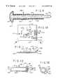
- FIG. 20is a side elevation sectional view of a bolt according to a further embodiment.
- electronic seal device 2includes a seal 4 and a bolt assembly 6 locked to the seal 4 .
- the bolt assembly 6locks hasps 8 , 8 ′ together.
- the hasps 8 , 8 ′may be part of a cargo container (not shown), for example, for locking the container door shut.
- the bolt assembly 6in one embodiment comprises a steel bolt 10 and electrically insulating thermoplastic tube 12 .
- Bolt 10comprises a shank 14 and a head 16 .
- the head and shankare a one piece metal structure and are electrically conductive as a single conductor.
- An annular locking groove 18is in the peripheral surface of the shank 14 adjacent to the shank tip 20 distal the head.
- the bolt 10is conventional and is, for example, for use with a bolt locking body as disclosed in the aforementioned U.S. Pat. No. 4,802,700 incorporated by reference herein in its entirety.
- the seal structure disclosed in this patentis by way of example and other seal structures employing bolts and locking bodies as disclosed in others of the aforementioned patents in the introductory portion or as otherwise know in this art may be employed in the alternative.
- the bolt 10is used with a locking mechanism 21 comprising a body 22 , FIG. 7 and a partial spring steel ring 24 , FIG. 8 .
- the ring 24is received in internal annular stepped groove 26 in the locking body 22 which also has a longitudinal bore 27 .
- the groove 26has an enlarged tapered section and a smaller diameter cylindrical portion.
- the ring 24 in the groove 26expands in the tapered section as the bolt shank is inserted.
- the ring 24then becomes aligned with the groove 18 in the bolt shank 14 and returns to its quiescent diameter by compressing partially into the shank groove.
- the ringis compressed further into the groove 18 of the bolt by a smaller diameter step 28 in the body groove 26 .
- the step 28 in the body groove 26 and the bolt 10 groove 18cooperate to lock the bolt to the body 22 to preclude further withdrawal of the bolt from the body 22 bore 27 .
- the bolt assembly 6also includes a thermoplastic tube 12 made of relatively stiff hard plastic material such as vinyl and the like.
- the tube 12has an elongated tubular body 32 with a bore 34 .
- the bore 34closely receives the bolt shank 14 , FIG. 5 .
- the body 32FIG. 12, terminates at one end in an enlarged radially outwardly extending annular bifurcated flange 36 having an annular groove 38 .
- a wire electrical conductor 40e.g., copper, is embedded within the tube 12 .
- the conductor 40has terminal ends 42 , 42 ′ protruding from the tube 12 at raised boss 44 radially extending from the tube flange 36 .
- the conductor 40extends along the axial length of the tube 12 .
- One portion 40 ′ of the conductorextends from end 42 linearly along one side of the tube 12 .
- a semi-annular conductor portion 45circumferentially extends about the tube 12 at end 46 distal the flange 36 for about 180°.
- a second portion 40 ′′extends axially on the opposite side of the tube 12 as portion 40 ′ terminating at end 42 ′.
- the portions 40 ′ and 40 ′′may also circumscribe the tube in the alternative, as they progress from ends 42 , 42 ′ to the annular portion 45 .
- the tube 12 bore 34is dimensioned to closely receive the bolt shank 14 .
- the tube end distal the flange 36abuts the bolt head 16 and the bolt shank 14 to form a fluid tight seal at the interface therebetween to preclude moisture from penetrating the interface.
- the seal 4comprises a preferably molded transparent thermoplastic housing 48 and an end rear wall assembly 50 .
- the housing 48 and assembly 50together form an interior chamber 51 , having sub-chambers 60 , 62 and 64 .
- a printed circuit board assembly 52is in chamber 60 , a pair of batteries 54 , a battery end contact 56 (FIG. 3) and battery contacts 58 are in sub-chamber 62 .
- the lock mechanism 21 and tube 12 flange 36are in sub-chamber 64 .
- the wall assembly 50comprises a molded transparent thermoplastic fixed wall 66 and a separate thermoplastic molded movable door 68 .
- the wall 66is permanently secured to the interior sides of the housing 48 by ultrasonic welding, heat welding or adhesive bonding or any other fixation process according to a given implementation.
- the tube 12 flange 36abuts the housing front wall 70 and is locked fixed in place by the abutment of the lock mechanism 21 body 22 , which may be press fit into generally circular cylindrical chamber 64 and abuts the flange 36 .
- Body 22abuts tubular member 102 (FIG. 2 ).
- a bore 72is in the front wall 70 for receiving therethrough the tube 12 .
- the front wall 70is thicker at the flange 36 in the bore 72 to reinforce this portion of the housing 48 .
- the wall assembly 50locks the tube 12 and locking mechanism 21 in the housing cavity.
- a pair of slots 74are in chamber 60 in opposite side walls of the housing 48 for slidably receiving the printed circuit board 52 ′ of assembly 52 .
- the board 52 ′overlies the wall 76 of the housing for the full extent of the wall 76 and is locked in place by the front wall 70 and rear wall assembly 50 .
- Rear wall assembly 50 fixed wall 66is generally rectangular preferably molded transparent thermoplastic.
- Wall 66fits snugly within the housing 48 .
- the wall 66has opposing mirror image U-shaped end portions 78 , 80 .
- the portions 78 and 80each have opposing aligned slots 82 and 84 , respectively.
- a pair of parallel arcuate elongated recesses 86are in a face 88 of wall 66 .
- a rectangular opening 90is formed in wall 66 adjacent to the recesses 86 and terminating at wall edge 92 .
- the recesses 86terminate in communication with the opposite wall edge 94 .
- the recesses 86are intermediate the slots 82 and 84 .
- the opening 90is defined by facing spaced edges 96 in wall 66 coextensive with the edges 96 ′ of the portions 78 and 80 .
- the edges 96taper somewhat in opposite directions away from opening 90 to serve as a lead in for a programming unit (not shown).
- wall 66 portion 78has a circular in plan view concave recess 98 for receiving the convex circular in section tip 20 of the received locked bolt shank 14 .
- the recess 98extends into the wall 66 from the interior face 100 extending past the slot 82 . In this way, the received bolt tip 20 passes through and blocks the slot 82 .
- a tubular member 102extends from wall 66 into the chamber 64 coextensive and concentric with the chamber 64 which is generally circular cylindrical.
- the tubular member 102has a longitudinally extending slot 104 .
- the bore of member 102receives the locked tip end of the received bolt shank 14 for aligning it with the recess 98 .
- Door 68has a central section 69 and a reduced thickness pair of opposite wing sections 106 , 108 which fit into and slide within the respective slots 82 and 84 of wall 66 .
- Section 106has a shorter length than section 108 to form a shoulder 110 .
- the shoulder 110abuts or may be closely spaced from the received tip 20 of the received bolt shank 14 .
- a pair of compression springs 112are received in grooves 114 in the side of the central section 69 .
- the grooves 114extend partially into the section 69 from door edge 116 .
- the springsare also received in the recesses 86 of the wall 66 . With the door 68 mounted in slots 82 and 84 , the door slides in directions 118 .
- the springs 112urge the door 68 in direction 118 ′ to close the opening 90 .
- printed circuit board assembly 52comprises a circuit board 120 with a programmable circuit 121 comprising a CPU 122 , a computer processing unit, memory 124 and other circuit components 126 such as crystals, capacitors and resistors for providing a programmable transmitting RFID tag circuit similar to the circuits of FIG. 19, or certain of the patents noted in the introductory portion incorporated by reference herein and modified as described herein.
- a programmable circuit 121comprising a CPU 122 , a computer processing unit, memory 124 and other circuit components 126 such as crystals, capacitors and resistors for providing a programmable transmitting RFID tag circuit similar to the circuits of FIG. 19, or certain of the patents noted in the introductory portion incorporated by reference herein and modified as described herein.
- the board 120has contacts 128 for receiving a programming portable unit (not shown) for programming the circuit 121 with a seal identification code, i.e., a unique number assigned a particular seal, geographic location where the seal is being deployed, container identification, e.g., a unique number assigned to a cargo container, the shipping carrier for the container, the container port of origin, container destination, inventory of the container and other data.
- a programming circuitis within the skill of one of ordinary skill in the computer programming art.
- the circuit 121is connected to the conductor 40 terminal ends 42 which completes the circuit.
- a resilient contact 130e.g., beryllium copper, is on the board 120 and connected to the circuit 121 for providing electrical battery power to the circuit by closing an ohmic connection between the circuit 121 and the batteries.
- the contact 56FIG. 3 provides a serial connection to opposite polarity terminals of the batteries 54 .
- the contact 130is S-shaped with a bent contact leg 132 for engaging the shank 14 during insertion and locking of the bolt and after the bolt is locked.
- the contact 130is mounted on the board 120 with a second leg 134 .
- the contact 130is ohmically connected to the circuit 121 .
- a further contact 136 on the circuit board 120is connected to the batteries to complete the circuit between the batteries and the circuit 121 .
- the circuit 121is also connected to a second battery contact 58 .
- the shank 14When the shank 14 is received in the seal 4 , the shank depresses the contact 130 into electrical ohmic connection with contact 136 , FIG. 11 . This arms the circuit. Subsequent interruption of a signal in the circuit 121 by breaking the conductor 40 is sensed by the circuit 121 in a sensor portion. This changes the codes in the circuit and causes the generation of a “tamper” signal, i.e., a second code.
- the tamper signalmay be the word “tamper” which is generated and transmitted instead of the normal signal or first code.
- Poweris supplied to the circuit 121 after the bolt is inserted by closure of the engaged contact 130 .
- the circuit 121FIG. 14, is a programmable RFID tag circuit including a controller comprising CPU 122 and memory 124 , e.g., an EPROM, an electronically programmable ROM, which is programmed by the portable programming unit forming the programming means 140 and other memory such as a ROM and so on.
- the circuit 121may include the circuit elements of the circuit of FIG. 19 and further including the prograrmmable EPROM.
- the circuit 121includes a transmitter 142 and a transmission antenna 144 .
- Transmitter 142once energized by the insertion of the bolt, transmits the encoded signal intermittently at random time intervals, for example, in the range of 1-10 seconds, and which may be conventional.
- the circuit 121includes a programmable arrangement for programming a given ID, the first code or normal signal.
- the depicted circuitincludes two embodiments.
- the bolt 10 with tube 12is shown connected to the control means of circuit 121 by solid line conductors.
- the bolt 146 of FIG. 9(or bolt 190 of FIGS. 17 and 18) in a second embodiment has the head and electrically conductive layer portion thereof shown connected to the circuit 121 by dashed lines to illustrate an alternative embodiment.
- the shank tip shownrepresents both embodiments.
- the ID information discussed aboveis programmed into the circuit 121 by the portable programming unit, programming means 140 . Programming and manufacturing such a programming unit is within the skill of one of ordinary skill in this art.
- the circuit 121begins transmission of the data, previously programmed into the circuit, via transmitter 142 or in the alternative, selectively in response to interrogation in a different embodiment.
- This dataincludes a first code manifesting the serial number of the seal device 2 and other data noted above.
- This datapreferably is transmitted periodically every few seconds at random intervals, for example, or upon interrogation, in the alternative.
- the batteriesare permanent and have a life sufficient for this purpose for the anticipated life of the seal device 2 .
- a locking boltis inserted, reference numeral 251 , into the seal. This activates the controller 253 which causes the first code signal generator 256 to generate a first code manifesting a locked seal.
- the transmitter 258 through the controller 253transmits the first code to a reader 250 , which may be conventional.
- the readerincludes an antenna, a receiver and a circuit for decoding the received signal and converting it to the desired data for further transmission or display.
- circuit 121If the circuit is interrupted, FIG. 14, e.g., by severing the conductor 40 in the tube 12 , the program of circuit 121 is programmed by the program in the memory 124 to immediately sense this condition. Electrical power is applied to the circuit at all times while the bolt is inserted.
- the circuit 121will transmit automatically or, in the alternative in a different embodiment, upon interrogation, via transmitter 142 , FIG. 14, a new code manifesting a tampering condition to the reader 250 .
- the interruption of the circuit 121 by a tampered bolt 259is sensed by the controller 253 which immediately causes the generation of the second code by generator 260 and disables the first code generation.
- Reader 250reads the seal data transmitted by transmitter 258 under control of the controller 253 .
- Antenna 144comprises a wound wire coil on the rear surface of the board 120 .
- the antennamay be covered by a label with the unique serial number. This number is visible through the housing 48 , which is transparent in this example, and which is the serial number programmed into the circuit 121 .
- the program of circuit 121in response to momentary interruption of power, or interruption of the circuit 121 by severing the conductor 40 , is programmed to transmit the message “tamper.”
- the reader 250FIG. 14 a , which may be hand held or permanently installed, adjacent to a conveyer of the cargo container or roadway for a trailer truck, receives the transmitted signal.
- the readeris coupled to a local, but remote computer (not shown).
- the tamper signal from the readeris forwarded to the computer which also indicates this state with a display and may be programmed to set off an audible and/or visual alarm also or in the alternative. This alarm is immediate and the transmitted signal immediately identifies the seal and the container that has been tampered with.
- the tamperingis noted at a given container location by reading the transmitted signal at different shipping and receiving points.
- the seal device 2In operation, the seal device 2 , FIG. 1 a is assembled without the bolt 10 attached or with the bolt temporarily attached exterior the housing 48 within the tube 12 .
- the seal at this timehas no identifying serial number programmed into the circuit 121 . However, the unique serial number is visible through the housing 48 on a label on the back of the circuit board 120 .
- the seal 4is then assigned a container (or door etc.) to be secured.
- a programming unit(not shown) is inserted through the door 68 , FIG. 1 a , opening 90 (FIG. 2 ).
- the programming unitis engaged with the contacts 128 , FIG. 10 of the circuit 121 .
- the unitprograms the unique data associated with this seal.
- the programming unitis then removed and the door 68 automatically shuts in response to the springs 112 .
- the bolt 10 shankis inserted fully into the tube 12 of the programmed device 2 until the bolt head 16 abuts the tube 12 end 46 , FIG. 12 .
- the seated shank tiplocks the door 68 shut so that the circuit 121 program can no longer be changed.
- the boltis permanently locked to the locking mechanism and can not be removed without destroying the bolt or seal 4 .
- the insertion of the shank 14closes the switch formed by contact 130 , FIG. 14, powering the circuit 121 and activating it.
- a signalis applied to and passes through the conductor 40 to and from the circuit 121 .
- This circuit 121is programmed to sense the presence of this signal to show the tamper state of the seal.
- the circuit 121once powered on, is armed and will transmit the programmed seal identification and related data to a local interrogator/receiver (not shown) upon interrogation.
- a signal separation circuitFor example, a circuit as disclosed in the aforementioned copending application incorporated by reference herein may be used or other known circuits as described in the introductory portion may be used.
- the circuit 121senses this and transmits “tamper.” Any attempt to cut or sever the tube 12 causes a “tamper” signal to be generated. The tamper signal is repetitively transmitted. Thus it is important that no interruption of the circuit occurs once the circuit is powered on and armed. Thus it is important that the contact 130 be arranged to provide positive ohmic connection to preclude any accidental interruption of power or signal to the circuit 121 . It is important that the contact 130 not disengage due to shock loads such as dropping and rough handling of the attached container. Contact 130 withstands such shock loading.
- a second embodiment of a sealcomprises a bolt 146 having a head 148 and a shank 150 .
- the bolt shank 150has a reduced diameter tip 154 in which annular groove 152 is formed. Groove 152 may be identical to groove 18 in the bolt 10 , FIG. 1 a , and serves the same purpose.
- the shank 150is larger in diameter than the shank 14 of the bolt 10 .
- the hasps 8 , 8 ′, FIG. 1, of containershave a maximum size bolt receiving openings 156 . Therefore, to accommodate the tube 12 of the FIG. 1 embodiment, the shank 14 of the bolt 10 is reduced in diameter accordingly. To make a more tamper resistant bolt requires the shank to be larger in diameter. Due to the limitation of the hasp aperture diameter, to make the shank larger requires eliminating the tube 12 .
- the tube 12is not required.
- a relatively thinner electrical insulating coating layer 158e.g., thermoplastic material, is deposited over the shank 150 for the length of the larger diameter portion 160 for a given distance from the bolt end.
- the layer 158extends for the length of the shank portion 160 and abuts the head 148 .
- a conductive coating layer 162is deposited over the head in electrically conductive ohmic contact with the electrically conductive metal head 148 .
- the coating layer 162is also deposited over a portion 164 of the insulating layer along a length of the shank 150 for a given distance from the bolt end.
- the layer 162may extend to about medially the length of the shank 150 .
- the tube 12may have a wall thickness of about 1.5 mm thick as compared to a thickness of about 0.01-0.05 mm for each of layers 162 and 164 .
- circuit board assembly 166includes contacts 168 on printed circuit board 169 for receiving the mating contacts of the programming unit as discussed above.
- the circuit 170 on the board 169may be substantially the same as the circuit 121 on the board assembly 52 of FIG. 10 .
- the assembly 166includes two spaced electrically isolated contacts 172 and 174 each of which is S-shaped and substantially the same in construction as contact 130 , FIG. 10 .
- the contacts 172 and 174are mounted on the board 169 .
- a connector 180 on the board 169is ohmically connected to contact 174 and is ohmically connected to contact pad 182 by conductor 184 .
- Conductor 184is connected to circuit 170 via pad 182 by other conductors not shown.
- Pads 181 and 183are coupled to positive and negative voltage sources, respectively.
- Pad 183is coupled to contact 172 and pad 181 is coupled to the circuit 121 .
- the ohmic connection of contacts 172 and 174completes the circuit 170 .
- the layer 162is ohmically connected to the shank at the head 148 which has no insulating layer.
- the circuit tampering sensing power signalpasses through the bolt via contact 172 at the bolt tip 154 and the contact 174 at the layer 162 .
- the coating layer 162is severed and the circuit broken because the head, connected ohmically to the coating layer 162 , is severed from the shank and the contact 174 is no longer ohmically connected to the contact 172 .
- the contact 174is no longer ohmically connected to the contact 172 .
- FIGS. 17 and 18a further embodiment of a bolt and locking seal arrangement is disclosed including a bolt assembly 190 , a locking body 192 secured to a housing such as housing 48 , FIG. 1 a , and a circuit and circuit board assembly 194 .
- the bolt assembly 190comprises a steel bolt 196 , an insulating powder coating 198 , a conductive paint coating 200 and a thermoplastic outer layer 202 .
- the bolt 196may be about 3.75 inches (9.5 cm) long and 0.312 inches (7.9 mm) diameter with a spherical or other shaped head 204 at one end.
- the bolt shank 197may be under cut slightly in the shank region receiving the coatings 198 and 200 to keep the shank diameter at a minimum for use with hasps as discussed above.
- the bolt head and shankare initially entirely coated with a rust and oxidation prevention electrically conductive coating (not shown) as known in the metal working art.
- a commercially available powdered electrically insulating coating 198is deposited over most of the bolt shank in the undercut region, e.g., starting about one inch from the narrowing tapered end 206 spaced from the locking groove 199 toward the head 204 and terminating at the base of the head 204 .
- the exposed bolt region 195only has the oxidation prevention coating and includes the locking groove 199 which receives the locking ring 201 .
- the body 192has a stepped groove 188 for receiving the ring 201 as described above.
- the coating 198is about 0.002-0.003 thick.
- the coatingmaybe any commercially available insulating material such as thermoplastics and
- the electrically conductive paint coating 200is deposited over the coating 198 and may be about 0.002-0.003 inches thick (0.05-0.08 mm).
- the coating 200is also deposited over the head 204 in electrically conductive contact with the bolt 196 head.
- the region 195is thus electrically conductive as exposed.
- the shank 198 and head 204are coated with an electrically insulating thermoplastic layer 202 preferably about 0.031 inches (0.8 mm) thick .
- the layer 202has a taper ed region 187 . This tapered region permits the bolt to be more easily inserted into a seal such as seal 4 , FIG. 1 .
- the layer 202terminates in this example about 1.625 inches (4.1 cm) from end 206 .
- the layer 202may be applied by injection molding.
- the layer 202serves as a moisture seal with the housing such as housing 48 when the bolt assembly is inserted into the seal housing protecting the interior components from moisture.
- the circuit board assembly 194has two spaced contacts 208 and 210 secured to board 212 .
- the locking body 192 in the assembled stateis spaced from and between the contacts 208 and 210 and does not engage the contacts 208 and 210 .
- Electrical connection of the contacts 208 and 210 by the switch action of the connection formed by the inserted bolt 196 electrically conductive regionsapplies power to the transmission and control circuit on the board 212 as discussed above with the other embodiments.
- the contact 210ohmically engages the shank 197 exposed region 195 .
- the contact 208ohmically engages the electrically conductive coating 200 .
- Coating 200is ohmically engaged with the shank 197 through its ohmic engagement with the head 204 . Since coating 200 is insulated from the shank 197 along the shank length no direct electrical ohmic engagement is made in this region by the contact 208 to the shank 197 in this region.
- the bolt assembly 190is inserted through the mating hasp 8 , 8 ′, FIG. 1 and into the housing such as housing 48 sub-chamber corresponding to sub-chamber 64 , FIG. 6 .
- the shank 197 tip region 195 adjacent to end 206ohmically engages the contact 210 , FIG. 17 .
- the groove 199engages and locks to the locking ring 201 in the locking body 192 .
- the contact 208ohmically engages the conductive coating 200 .
- the circuit assembly 194begins transmission. Electrical continuity is provided by the shank 197 at region 195 from contact 210 to the head 204 to the conductive layer 200 ohmically connected to the head 204 electrically conductive region. This connects contacts 208 and 210 .
- the tapered region 187assists in insertion of the bolt into the housing sub-chamber corresponding to sub-chamber 64 . This provides a tight interference friction fit between the layer 202 and the housing corresponding to housing 48 providing moisture sealing therebetween. Only the bolt portion with the layer 202 extends beyond the housing.
- the coating 198insulates the coating 200 from engaging the shank except at the head 204 where there is no coating 198 .
- a bolt 261in a further alternative embodiment, includes a metal head 262 , which may be of any shape such as a disk and so on, having a circular cylindrical recess 263 .
- a metal tube 264which is steel or stainless steel or other hard tough metal is welded or otherwise permanently fastened to the head 262 in the recess 263 such as by swaging and so on.
- the end of the tube 264is tapered in a frusto-conical tip 265 .
- the tip 265has a reduced diameter opening in communication with the tube hollow core 266 .
- a stiff insulated wire 267 of relatively heavy gauge, for example, having a diameter slightly smaller than the diameter of the tube core 266is in the core 266 .
- the wire 267has a bare uninsulated metal conductor 267 ′ exposed at the head 262 end of the wire 267 .
- Conductor 267 ′abuts the head in ohmic conductive contact therewith.
- the other end of the wire 267passes through the reduced diameter opening in the tube tip 165 and may be held there by crushing the tip 265 end somewhat against the wire 267 insulation, crimping the wire thereto.
- a metal ring 268is ohmically fastened to the wire 267 metal conductor at the exposed wire end such as by soldering and so on.
- Wall 66 ′ of the seal housingcorresponds to the wall 66 of assembly 50 .
- Tubular member 102 , FIGS. 4 and 5is replaced with a tubular member 269 , FIG. 20, and which receives the tip end of the tube 264 and the ring 268 .
- a contact 270is attached to the wall 66 ′ and located in the hollow core of the member 269 . This contact replaces the contact 172 , FIG. 16 of board 169 , the board 169 circuit 170 otherwise being the same for use with the bolt 261 .
- the contact 270is connected similarly to the circuit 170 as contact 172 .
- the tube 264has a locking ring groove 272 for engagement with a locking body as discussed above in connection with FIGS. 5-7.
- the tube or boltsmay have locking grooves for engagement with locking collets as known in the seal art such as shown in U.S. Pat. Nos. 5,450,657, 5,582,447, 5,413,393 and 5,347,689, all incorporated by reference herein.
- the ohmic engagement of the wire 267 conductor 267 ′disengages ohmically from the head 262 and results in the generation of the tamper signal as discussed above. If the medial portion shaft of the tube 264 is severed the ohmic contact of the wire 267 ′ to the head will be interrupted and result in a tamper signal. Any displacement of the head relative to the conductor 267 ′ provides the same tamper signal result.
- the locking mechanisms, the power source, the bolt configuration, the information stored and transmitted, the use of a movable door and a transparent housingmay be changed according to a given implementation.
- the end wall assemblymay include locking devices for permanently locking the assembly to the housing without a door.
- the antennamay be attached to the housing rather than the circuit board.
- the serial numbermay be attached to the housing rather than the circuit board.
- the contact arrangementsmay differ from the disclosed embodiments.
- an elongated insulating membersuch as a rod or coating layer of any cross section shape in place of the tube or coating disclosed may be used for forming a key along the shank, the housing having a mating keyway for receiving the key.
- One or more conductorsare located within or adjacent to the insulating member and make ohmic contact with the bolt at the bolt head and/or at other spaced locations along the shank, each location forming a completed separate power supply circuit with the control means.
- Momentary separation of the bolt from the contacts or severing the bolt so that there is interruption of the signal to the signal sensing portion of the circuitcauses the generation of a tamper signal.
- the tamper signalmay comprise any suitable signal recognized as a tampered condition and transmission of the word “tamper” is given by way of illustration.
Landscapes
- Engineering & Computer Science (AREA)
- Computer Security & Cryptography (AREA)
- Physics & Mathematics (AREA)
- General Physics & Mathematics (AREA)
- Theoretical Computer Science (AREA)
- Mechanical Engineering (AREA)
- Lock And Its Accessories (AREA)
- Glass Compositions (AREA)
- Adhesives Or Adhesive Processes (AREA)
- Non-Metallic Protective Coatings For Printed Circuits (AREA)
- Processing And Handling Of Plastics And Other Materials For Molding In General (AREA)
- Burglar Alarm Systems (AREA)
- Casings For Electric Apparatus (AREA)
Abstract
Description
Claims (22)
Priority Applications (10)
| Application Number | Priority Date | Filing Date | Title |
|---|---|---|---|
| US09/293,135US6265973B1 (en) | 1999-04-16 | 1999-04-16 | Electronic security seal |
| AU42298/00AAU4229800A (en) | 1999-04-16 | 2000-04-11 | Electronic security seal |
| CNB008062862ACN1160211C (en) | 1999-04-16 | 2000-04-11 | Electronic security seal |
| DK00922055TDK1171330T3 (en) | 1999-04-16 | 2000-04-11 | Electronic security seal |
| AT00922055TATE269804T1 (en) | 1999-04-16 | 2000-04-11 | ELECTRONIC SECURITY SEAL |
| PCT/US2000/009634WO2000063052A1 (en) | 1999-04-16 | 2000-04-11 | Electronic security seal |
| EP00922055AEP1171330B1 (en) | 1999-04-16 | 2000-04-11 | Electronic security seal |
| DE60011759TDE60011759D1 (en) | 1999-04-16 | 2000-04-11 | ELECTRONIC SECURITY SEAL |
| HK02101223.5AHK1039921B (en) | 1999-04-16 | 2000-04-11 | Electronic security seal |
| MYPI20001606AMY124022A (en) | 1999-04-16 | 2000-04-14 | Electronic security seal |
Applications Claiming Priority (1)
| Application Number | Priority Date | Filing Date | Title |
|---|---|---|---|
| US09/293,135US6265973B1 (en) | 1999-04-16 | 1999-04-16 | Electronic security seal |
Publications (1)
| Publication Number | Publication Date |
|---|---|
| US6265973B1true US6265973B1 (en) | 2001-07-24 |
Family
ID=23127799
Family Applications (1)
| Application Number | Title | Priority Date | Filing Date |
|---|---|---|---|
| US09/293,135Expired - LifetimeUS6265973B1 (en) | 1999-04-16 | 1999-04-16 | Electronic security seal |
Country Status (10)
| Country | Link |
|---|---|
| US (1) | US6265973B1 (en) |
| EP (1) | EP1171330B1 (en) |
| CN (1) | CN1160211C (en) |
| AT (1) | ATE269804T1 (en) |
| AU (1) | AU4229800A (en) |
| DE (1) | DE60011759D1 (en) |
| DK (1) | DK1171330T3 (en) |
| HK (1) | HK1039921B (en) |
| MY (1) | MY124022A (en) |
| WO (1) | WO2000063052A1 (en) |
Cited By (129)
| Publication number | Priority date | Publication date | Assignee | Title |
|---|---|---|---|---|
| USD454773S1 (en) | 2001-08-27 | 2002-03-26 | Transguard Industries, Inc. | Bolt with oval head |
| USD455330S1 (en) | 2001-08-27 | 2002-04-09 | Transguard Industries, Inc. | Bolt with facetted head |
| USD462600S1 (en) | 2001-08-27 | 2002-09-10 | Transguard Industries, Inc. | Bolt with round head |
| US20030030542A1 (en)* | 2001-08-10 | 2003-02-13 | Von Hoffmann Gerard | PDA security system |
| RU2202720C1 (en)* | 2002-06-19 | 2003-04-20 | Закрытое акционерное общество "Энергет и Ко" | Cable length clamping device |
| US20040041706A1 (en)* | 2002-09-04 | 2004-03-04 | Stratmoen Scott Alan | Smart and secure container |
| US20040108938A1 (en)* | 2002-12-10 | 2004-06-10 | Entrekin David A. | Portable electronic locking system and method |
| US20040113782A1 (en)* | 2002-12-11 | 2004-06-17 | Hi-G-Tek Ltd. | Tamper-resistant electronic seal |
| US20040135668A1 (en)* | 2002-10-24 | 2004-07-15 | Hoffer Erik H. | Closure system and method |
| US20040187532A1 (en)* | 2003-03-28 | 2004-09-30 | Hui-Hua Hsieh | Remote-controlled lock |
| US20040246097A1 (en)* | 2003-06-05 | 2004-12-09 | Queenan Joseph A. | Secure electronic compartment identifier system |
| US6846024B1 (en) | 2001-03-30 | 2005-01-25 | Gabriel Technologies Corp. | Security cover system for cargo container latch |
| US20050023844A1 (en)* | 2003-07-30 | 2005-02-03 | Itw Limited | Sealing device |
| US20050034420A1 (en)* | 2001-11-20 | 2005-02-17 | Radlinger Steven C. | Secure package system and method |
| US20050063125A1 (en)* | 2003-08-07 | 2005-03-24 | Piolax Inc. | Connection structure or fastening structure |
| WO2005027079A1 (en)* | 2003-09-15 | 2005-03-24 | Andrew Gerald Lynn Brown | A seal |
| US20050110635A1 (en)* | 2003-03-20 | 2005-05-26 | Giermanski James R. | System, methods and computer program products for monitoring transport containers |
| US20050144991A1 (en)* | 2004-01-06 | 2005-07-07 | Bravo Ramiro H. | Reusable hasp-locking mechanism |
| US20050179548A1 (en)* | 2004-02-13 | 2005-08-18 | Kittel Mark D. | Tamper monitoring article, system and method |
| US20050210932A1 (en)* | 2002-05-13 | 2005-09-29 | European Community | Multi-purpose seal with lock |
| US20050231365A1 (en)* | 2004-03-30 | 2005-10-20 | Tester Theodore R | Electronic security seal |
| US20050253708A1 (en)* | 2004-04-07 | 2005-11-17 | Karl Bohman | Method and system for arming a container security device without use of electronic reader |
| US20050263602A1 (en)* | 2004-05-31 | 2005-12-01 | Lien-Feng Lin | Electronic seal |
| US20050279820A1 (en)* | 2004-06-16 | 2005-12-22 | Patrick Moynihan | Vehicle violation enforcement system and method |
| US20050289233A1 (en)* | 2004-06-24 | 2005-12-29 | International Business Machines Corporation | Autonomic self-surveillance system and method for supported equipment |
| US20060019745A1 (en)* | 2004-07-22 | 2006-01-26 | Igt | Remote gaming eligibility system and method using RFID tags |
| US20060044110A1 (en)* | 2004-08-31 | 2006-03-02 | Napolitano Thomas J | System and method for detecting access to an article or opening of a package |
| WO2006032166A1 (en)* | 2004-09-23 | 2006-03-30 | Lien-Feng Lin | Tamper-resistant lock with function of identification |
| US20060077056A1 (en)* | 2004-10-06 | 2006-04-13 | Bernal-Silva Richard A | Article locating system |
| US7044512B1 (en)* | 2004-07-12 | 2006-05-16 | Moreno Jose M | Bar seal for shipping container |
| US20060152366A1 (en)* | 2003-02-24 | 2006-07-13 | Marco Sironi | Multiple transponder seal device |
| US20060202824A1 (en)* | 2005-02-04 | 2006-09-14 | Container Security Inc. | Electronic seal and method of shipping container tracking |
| US20060213988A1 (en)* | 2005-03-28 | 2006-09-28 | Chih-Hsin Wang | System for tracking elements using tags |
| US20060214794A1 (en)* | 2005-03-28 | 2006-09-28 | Chih-Hsin Wang | Secure system for tracking elements using tags |
| US20060220855A1 (en)* | 2005-03-18 | 2006-10-05 | Hartmann Clinton S | Tamper indicating saw tag system and method for using same |
| US20060250217A1 (en)* | 2005-05-09 | 2006-11-09 | Safetystream Mobile Limited | Method for using a table of data to control access and a locking mechanism using same |
| US20060255119A1 (en)* | 2004-06-16 | 2006-11-16 | Marchasin Cory D | Parking environment management system and method |
| US20060261959A1 (en)* | 2005-04-26 | 2006-11-23 | David Worthy | Tamper monitoring system and method |
| US20060266087A1 (en)* | 2004-11-12 | 2006-11-30 | Hamilton Eric K | Locking device |
| US20070024066A1 (en)* | 2005-07-29 | 2007-02-01 | Terry Daniel J | Bolt-type seal lock |
| US20070080802A1 (en)* | 2005-08-22 | 2007-04-12 | Cockburn John M | Tamper & intrusion detection device |
| US20070103310A1 (en)* | 2005-11-04 | 2007-05-10 | Hopman Nicholas C | Asset seal device and method |
| US20070102529A1 (en)* | 2005-11-08 | 2007-05-10 | Macsema, Inc. | Information devices |
| US20070112620A1 (en)* | 2005-11-16 | 2007-05-17 | Josiah Johnson | Permit-based parking environment management method and system |
| US20070120381A1 (en)* | 2005-11-15 | 2007-05-31 | Jakob Ehrensvard | Electronic tamper evident seal |
| US20070126589A1 (en)* | 2004-12-20 | 2007-06-07 | Linda Jacober | RFID Tag Label |
| US20070139196A1 (en)* | 2004-12-23 | 2007-06-21 | Manfred Rietzler | Seal device |
| US20070240578A1 (en)* | 2006-04-12 | 2007-10-18 | Dileo Anthony | Filter with memory, communication and temperature sensor |
| US20070241510A1 (en)* | 2006-04-12 | 2007-10-18 | Dileo Anthony | Filter seating monitor |
| US20070243113A1 (en)* | 2006-04-12 | 2007-10-18 | Dileo Anthony | Filter with memory, communication and concentration sensor |
| US20070262850A1 (en)* | 2004-07-06 | 2007-11-15 | Tagmaster Ab | Electronic Security Seal |
| US20070271544A1 (en)* | 2006-05-19 | 2007-11-22 | Rolf Engstrom | Security sensing module envelope |
| US20070285232A1 (en)* | 2005-05-13 | 2007-12-13 | Karl Bohman | Method and system for arming a multi-layered security system |
| US20080106415A1 (en)* | 2006-11-08 | 2008-05-08 | Macsema, Inc. | Information tag |
| US20080122620A1 (en)* | 2006-11-29 | 2008-05-29 | Motorola, Inc. | Attachment device, attachment receiving device and system for identifying secured containers |
| US20080143123A1 (en)* | 2005-05-31 | 2008-06-19 | Dewalch Norman Binz | Locking apparatus and method |
| US20080218353A1 (en)* | 2007-03-09 | 2008-09-11 | Savi Technology, Inc. | Method and Apparatus Using Magnetic Flux for Container Security |
| WO2005117535A3 (en)* | 2004-05-27 | 2008-10-02 | Brammall Inc | Locking device |
| US20080295555A1 (en)* | 2005-12-08 | 2008-12-04 | Amplus Communication Pte Ltd | Locking Seal With Tamper Indication And Notification Device |
| US20090009328A1 (en)* | 2006-09-13 | 2009-01-08 | Savi Technology, Inc. | Bolt for Security Seal |
| US20090037146A1 (en)* | 2005-11-14 | 2009-02-05 | Trowbridge Jr Jack I | System and methods for testing, monitoring, and replacing equipment |
| US20090072554A1 (en)* | 2007-09-13 | 2009-03-19 | United Security Applications Id. Inc. | Pin-style cargo seal with removable tracking module |
| US20090091144A1 (en)* | 2007-10-05 | 2009-04-09 | Robert Debrody | Bolt Security Seal with Reusable Electronics Module and Bolt |
| US20090102653A1 (en)* | 2007-10-19 | 2009-04-23 | Mcginnis John | Method for Maintaining a Shipping Container Manifest |
| US20090108596A1 (en)* | 2005-07-29 | 2009-04-30 | Terahop Networks, Inc. | Shipping container security system |
| US20090121877A1 (en)* | 2005-01-14 | 2009-05-14 | Matthew Henderson | Transponder bolt seal and a housing for a transponder |
| US20090139336A1 (en)* | 2005-11-14 | 2009-06-04 | Trowbridge Jr Jack I | Systems and methods for monitoring system performance |
| US20090179757A1 (en)* | 2008-01-14 | 2009-07-16 | Cohn Oded Yair | Electronic security seal and system |
| US20090212950A1 (en)* | 2008-02-26 | 2009-08-27 | Jin-Hao Chao Cheng | RFID cargo/storage container tamper seal |
| WO2010028258A1 (en)* | 2008-09-05 | 2010-03-11 | Lock II, L.L.C. | High security lock |
| US20100116884A1 (en)* | 2006-04-18 | 2010-05-13 | Dean Alderucci | Systems and methods for providing access to wireless gaming devices |
| US20100156164A1 (en)* | 2008-12-22 | 2010-06-24 | Toyota Motor Engineering & Manufacturing North America, Inc. | Multiple part resin seat back with integrated adjustable headrest support |
| US20100180649A1 (en)* | 2009-01-20 | 2010-07-22 | Harvey Michael P | Self-powered electronic lock |
| US20100201486A1 (en)* | 2009-02-09 | 2010-08-12 | Paul Llewellyn Greene | Shipping container integrity device and system |
| US20100238032A1 (en)* | 2009-03-20 | 2010-09-23 | Paul Llewellyn Greene | Shipping container integrity device and system |
| CN101504807B (en)* | 2004-09-23 | 2010-11-10 | 辛耘企业股份有限公司 | System for managing container by using electronic seal and electronic seal |
| US20100283578A1 (en)* | 2007-06-15 | 2010-11-11 | Matthew Henderson | Transponder Bolt Seal and a Housing for a Transponder |
| US20100295255A1 (en)* | 2005-05-31 | 2010-11-25 | Dewalch Norman Binz | Retaining apparatus for a seal |
| WO2011008871A1 (en)* | 2009-07-14 | 2011-01-20 | Savi Networks Llc | Security seal |
| US20110094310A1 (en)* | 2006-04-12 | 2011-04-28 | Millipore Corporation | Filter with memory, communication and pressure sensor |
| US20110094951A1 (en)* | 2006-04-12 | 2011-04-28 | Millipore Corporation | Filter with memory, communication and pressure sensor |
| US20110204656A1 (en)* | 2009-01-27 | 2011-08-25 | Simon Lai | Electronic Seal |
| US20110273852A1 (en)* | 2007-10-05 | 2011-11-10 | Robert Debrody | Reusable Bolt Electronic Seal Module with GPS/Cellular Phone Communications & Tracking System |
| US8162756B2 (en) | 2004-02-25 | 2012-04-24 | Cfph, Llc | Time and location based gaming |
| US8167213B1 (en)* | 2010-05-19 | 2012-05-01 | Williams-Pyro, Inc. | System and method of tagging an ordnance |
| US8292741B2 (en) | 2006-10-26 | 2012-10-23 | Cfph, Llc | Apparatus, processes and articles for facilitating mobile gaming |
| US8314704B2 (en) | 2009-08-28 | 2012-11-20 | Deal Magic, Inc. | Asset tracking using alternative sources of position fix data |
| US8319601B2 (en) | 2007-03-14 | 2012-11-27 | Cfph, Llc | Game account access device |
| US8334773B2 (en) | 2009-08-28 | 2012-12-18 | Deal Magic, Inc. | Asset monitoring and tracking system |
| US20130008087A1 (en)* | 2010-03-29 | 2013-01-10 | Deutsche Post Ag | Sealing System for Sealing of Doors of Transport Vehicles with Door Specific Seals |
| US8397985B2 (en) | 2006-05-05 | 2013-03-19 | Cfph, Llc | Systems and methods for providing access to wireless gaming devices |
| US8432274B2 (en) | 2009-07-31 | 2013-04-30 | Deal Magic, Inc. | Contextual based determination of accuracy of position fixes |
| EP2590154A1 (en) | 2011-11-02 | 2013-05-08 | Nafith Logistics Psc. | Secure sealing device |
| US8456302B2 (en) | 2009-07-14 | 2013-06-04 | Savi Technology, Inc. | Wireless tracking and monitoring electronic seal |
| US8504617B2 (en) | 2004-02-25 | 2013-08-06 | Cfph, Llc | System and method for wireless gaming with location determination |
| US8510567B2 (en) | 2006-11-14 | 2013-08-13 | Cfph, Llc | Conditional biometric access in a gaming environment |
| US8506400B2 (en) | 2005-07-08 | 2013-08-13 | Cfph, Llc | System and method for wireless gaming system with alerts |
| US8564410B2 (en) | 2010-05-20 | 2013-10-22 | Paul Llewellyn Greene | Shipping container security process |
| US20130277989A1 (en)* | 2012-04-19 | 2013-10-24 | Nic Products Inc. | Lock bolt |
| US8581721B2 (en) | 2007-03-08 | 2013-11-12 | Cfph, Llc | Game access device with privileges |
| US8613658B2 (en) | 2005-07-08 | 2013-12-24 | Cfph, Llc | System and method for wireless gaming system with user profiles |
| US8635893B2 (en) | 2008-09-05 | 2014-01-28 | Lock II, L.L.C. | High security lock |
| US8645709B2 (en) | 2006-11-14 | 2014-02-04 | Cfph, Llc | Biometric access data encryption |
| US8690679B2 (en) | 2005-08-09 | 2014-04-08 | Cfph, Llc | System and method for providing wireless gaming as a service application |
| EP2743864A1 (en) | 2012-12-17 | 2014-06-18 | Nafith Logistics Psc. | Secure sealing device and method |
| US8784197B2 (en) | 2006-11-15 | 2014-07-22 | Cfph, Llc | Biometric access sensitivity |
| US8840018B2 (en) | 2006-05-05 | 2014-09-23 | Cfph, Llc | Device with time varying signal |
| WO2014140917A3 (en)* | 2013-03-15 | 2014-12-24 | Assa Abloy Ab | Tamper credential |
| US8956231B2 (en) | 2010-08-13 | 2015-02-17 | Cfph, Llc | Multi-process communication regarding gaming information |
| US8974302B2 (en) | 2010-08-13 | 2015-03-10 | Cfph, Llc | Multi-process communication regarding gaming information |
| WO2015127200A1 (en)* | 2014-02-20 | 2015-08-27 | Teeter Charles Michael | Disposable and tamper-resistant rfid lock |
| US9175501B2 (en) | 2013-05-14 | 2015-11-03 | Nic Products, Inc. | Rotary security seal |
| US9177282B2 (en) | 2009-08-17 | 2015-11-03 | Deal Magic Inc. | Contextually aware monitoring of assets |
| US9183693B2 (en) | 2007-03-08 | 2015-11-10 | Cfph, Llc | Game access device |
| US9361776B2 (en) | 2006-12-19 | 2016-06-07 | Charles Michael Teeter | Disposable and tamper-resistant RFID lock |
| US20170016841A1 (en)* | 2015-07-13 | 2017-01-19 | Jamie M. Smith | System and Method for Thread Protrusion Verification |
| US9646472B2 (en) | 2012-08-15 | 2017-05-09 | Payment Express Limited | Tamper evident systems |
| US20170284130A1 (en)* | 2012-03-09 | 2017-10-05 | Neology, Inc. | Tamper evident cargo container seal bolt lock |
| US9978235B2 (en)* | 2015-07-02 | 2018-05-22 | Tyco Fire & Security Gmbh | Multi-technology transponder and system |
| WO2018091053A1 (en) | 2016-11-15 | 2018-05-24 | Lyngsoe Systems Ltd | Electronic cable seal |
| US10145146B2 (en) | 2012-03-19 | 2018-12-04 | Neology, Inc. | Tamper evident cargo container seal bolt lock |
| US10186176B2 (en) | 2013-05-14 | 2019-01-22 | Nic Products, Inc. | Rotary security seal |
| USRE47678E1 (en) | 2004-06-16 | 2019-10-29 | Ipt, Llc | Parking environment management system and method |
| US10460566B2 (en) | 2005-07-08 | 2019-10-29 | Cfph, Llc | System and method for peer-to-peer wireless gaming |
| US10535221B2 (en) | 2006-10-26 | 2020-01-14 | Interactive Games Llc | System and method for wireless gaming with location determination |
| US10726664B2 (en) | 2004-02-25 | 2020-07-28 | Interactive Games Llc | System and method for convenience gaming |
| US11410578B2 (en)* | 2016-02-15 | 2022-08-09 | The European Atomic Energy Community (Euratom), Represented By The European Commission | Sealing bolt and method of installing a sealing bolt |
| US12400518B2 (en) | 2006-05-05 | 2025-08-26 | Interactive Games Llc | System for facilitating online wagering with nearby mobile phones |
| US12409382B2 (en) | 2010-08-13 | 2025-09-09 | Interactive Games Llc | Smart phone with wrapper application that checks whether the smart phone may use a gambling application |
Families Citing this family (6)
| Publication number | Priority date | Publication date | Assignee | Title |
|---|---|---|---|---|
| FR2816434A1 (en)* | 2000-11-06 | 2002-05-10 | Robert Stephan Touzet | Seal using an electronic chip for transport vehicles or containers, uses chip with memory which records shipping data and opening of the seal, and also stores a digital signature |
| US20030011474A1 (en)* | 2001-07-13 | 2003-01-16 | Ng Sing King | Circuit and method for electronic security seal |
| DE102004042436A1 (en)* | 2004-08-31 | 2006-03-02 | Max Kibellus | Safety lock for protecting object in container e.g. envelope, has pin including heading section, and housing including electromagnetic locking device that interacts with pin and is codable |
| CN100500525C (en)* | 2005-10-19 | 2009-06-17 | 李树群 | Disposable passive radio frequency electronic lock |
| CN101086797B (en)* | 2006-06-07 | 2012-08-22 | 万家盛 | An electronic group encapsulation |
| CN101494009A (en)* | 2008-01-24 | 2009-07-29 | 上海英颁斯物流科技有限公司 | Apparatus and method for identifying container being unlocked |
Citations (20)
| Publication number | Priority date | Publication date | Assignee | Title |
|---|---|---|---|---|
| US3727210A (en)* | 1971-04-23 | 1973-04-10 | Minnesota Mining & Mfg | Lock and alarm device |
| US4982985A (en) | 1989-03-06 | 1991-01-08 | E.J. Brooks Company | Bolt type seal with fiber optic seal |
| US5125700A (en)* | 1990-07-30 | 1992-06-30 | Fattori Lazzaro A | Security seal |
| US5127687A (en)* | 1990-10-17 | 1992-07-07 | E. J. Brooks Co. | Tamper indicator for a locking seal |
| US5189396A (en) | 1990-06-16 | 1993-02-23 | Anatoli Stobbe | Electronic seal |
| EP0574230A1 (en) | 1992-06-09 | 1993-12-15 | Hartbrook Properties Limited | Property protection system |
| US5347689A (en) | 1993-06-08 | 1994-09-20 | E. J. Brooks Company | Reusable bolt seal |
| US5413393A (en) | 1993-08-13 | 1995-05-09 | E.J. Brooks Company | Reusable seal for use with rod |
| US5450657A (en) | 1993-05-21 | 1995-09-19 | E. J. Brooks Company | Seal |
| US5479160A (en) | 1993-10-01 | 1995-12-26 | Amtech Corporation | Low level RF threshold detector |
| US5485154A (en) | 1987-12-04 | 1996-01-16 | Magellan Corporation (Australia) Pty. Ltd. | Communication device and method(s) |
| US5541604A (en) | 1993-09-03 | 1996-07-30 | Texas Instruments Deutschland Gmbh | Transponders, Interrogators, systems and methods for elimination of interrogator synchronization requirement |
| US5582447A (en) | 1995-02-24 | 1996-12-10 | E. J. Brooks Company | Locking device with serpentine gripping member |
| US5587702A (en)* | 1992-11-12 | 1996-12-24 | Chadfield; Garth R. | Padlock with tamper alarm |
| US5656996A (en) | 1996-03-13 | 1997-08-12 | Global Associates, Ltd. | Electronic security bonding device |
| FR2746944A1 (en) | 1996-03-28 | 1997-10-03 | Teaupel Rene | Rivet with tamper warning for attaching identification piece to support |
| US5729199A (en) | 1996-06-06 | 1998-03-17 | Consolidated Graphic Materials, Inc. | Security system for a metallic enclosure |
| US5736924A (en)* | 1995-09-01 | 1998-04-07 | Shieh; Jin-Ren | Alarm lock |
| US5801618A (en) | 1996-02-08 | 1998-09-01 | Jenkins; Mark | Vehicle alarm and lot monitoring system |
| US6069563A (en)* | 1996-03-05 | 2000-05-30 | Kadner; Steven P. | Seal system |
- 1999
- 1999-04-16USUS09/293,135patent/US6265973B1/ennot_activeExpired - Lifetime
- 2000
- 2000-04-11DKDK00922055Tpatent/DK1171330T3/enactive
- 2000-04-11DEDE60011759Tpatent/DE60011759D1/ennot_activeExpired - Lifetime
- 2000-04-11AUAU42298/00Apatent/AU4229800A/ennot_activeAbandoned
- 2000-04-11WOPCT/US2000/009634patent/WO2000063052A1/enactiveIP Right Grant
- 2000-04-11HKHK02101223.5Apatent/HK1039921B/enunknown
- 2000-04-11EPEP00922055Apatent/EP1171330B1/ennot_activeExpired - Lifetime
- 2000-04-11ATAT00922055Tpatent/ATE269804T1/ennot_activeIP Right Cessation
- 2000-04-11CNCNB008062862Apatent/CN1160211C/ennot_activeExpired - Lifetime
- 2000-04-14MYMYPI20001606Apatent/MY124022A/enunknown
Patent Citations (20)
| Publication number | Priority date | Publication date | Assignee | Title |
|---|---|---|---|---|
| US3727210A (en)* | 1971-04-23 | 1973-04-10 | Minnesota Mining & Mfg | Lock and alarm device |
| US5485154A (en) | 1987-12-04 | 1996-01-16 | Magellan Corporation (Australia) Pty. Ltd. | Communication device and method(s) |
| US4982985A (en) | 1989-03-06 | 1991-01-08 | E.J. Brooks Company | Bolt type seal with fiber optic seal |
| US5189396A (en) | 1990-06-16 | 1993-02-23 | Anatoli Stobbe | Electronic seal |
| US5125700A (en)* | 1990-07-30 | 1992-06-30 | Fattori Lazzaro A | Security seal |
| US5127687A (en)* | 1990-10-17 | 1992-07-07 | E. J. Brooks Co. | Tamper indicator for a locking seal |
| EP0574230A1 (en) | 1992-06-09 | 1993-12-15 | Hartbrook Properties Limited | Property protection system |
| US5587702A (en)* | 1992-11-12 | 1996-12-24 | Chadfield; Garth R. | Padlock with tamper alarm |
| US5450657A (en) | 1993-05-21 | 1995-09-19 | E. J. Brooks Company | Seal |
| US5347689A (en) | 1993-06-08 | 1994-09-20 | E. J. Brooks Company | Reusable bolt seal |
| US5413393A (en) | 1993-08-13 | 1995-05-09 | E.J. Brooks Company | Reusable seal for use with rod |
| US5541604A (en) | 1993-09-03 | 1996-07-30 | Texas Instruments Deutschland Gmbh | Transponders, Interrogators, systems and methods for elimination of interrogator synchronization requirement |
| US5479160A (en) | 1993-10-01 | 1995-12-26 | Amtech Corporation | Low level RF threshold detector |
| US5582447A (en) | 1995-02-24 | 1996-12-10 | E. J. Brooks Company | Locking device with serpentine gripping member |
| US5736924A (en)* | 1995-09-01 | 1998-04-07 | Shieh; Jin-Ren | Alarm lock |
| US5801618A (en) | 1996-02-08 | 1998-09-01 | Jenkins; Mark | Vehicle alarm and lot monitoring system |
| US6069563A (en)* | 1996-03-05 | 2000-05-30 | Kadner; Steven P. | Seal system |
| US5656996A (en) | 1996-03-13 | 1997-08-12 | Global Associates, Ltd. | Electronic security bonding device |
| FR2746944A1 (en) | 1996-03-28 | 1997-10-03 | Teaupel Rene | Rivet with tamper warning for attaching identification piece to support |
| US5729199A (en) | 1996-06-06 | 1998-03-17 | Consolidated Graphic Materials, Inc. | Security system for a metallic enclosure |
Cited By (287)
| Publication number | Priority date | Publication date | Assignee | Title |
|---|---|---|---|---|
| US7117712B1 (en) | 2001-03-30 | 2006-10-10 | Gabriel Technologies Corp. | Removal tool |
| US6846024B1 (en) | 2001-03-30 | 2005-01-25 | Gabriel Technologies Corp. | Security cover system for cargo container latch |
| US20030030542A1 (en)* | 2001-08-10 | 2003-02-13 | Von Hoffmann Gerard | PDA security system |
| US20050151623A1 (en)* | 2001-08-10 | 2005-07-14 | Von Hoffmann Gerard | PDA security system |
| USD455330S1 (en) | 2001-08-27 | 2002-04-09 | Transguard Industries, Inc. | Bolt with facetted head |
| USD462600S1 (en) | 2001-08-27 | 2002-09-10 | Transguard Industries, Inc. | Bolt with round head |
| USD454773S1 (en) | 2001-08-27 | 2002-03-26 | Transguard Industries, Inc. | Bolt with oval head |
| US20050034420A1 (en)* | 2001-11-20 | 2005-02-17 | Radlinger Steven C. | Secure package system and method |
| US20050210932A1 (en)* | 2002-05-13 | 2005-09-29 | European Community | Multi-purpose seal with lock |
| US7178369B2 (en)* | 2002-05-13 | 2007-02-20 | European Community | Multi-purpose seal with lock |
| RU2202720C1 (en)* | 2002-06-19 | 2003-04-20 | Закрытое акционерное общество "Энергет и Ко" | Cable length clamping device |
| US7002472B2 (en) | 2002-09-04 | 2006-02-21 | Northrop Grumman Corporation | Smart and secure container |
| US20040041706A1 (en)* | 2002-09-04 | 2004-03-04 | Stratmoen Scott Alan | Smart and secure container |
| US20040135668A1 (en)* | 2002-10-24 | 2004-07-15 | Hoffer Erik H. | Closure system and method |
| US20040108938A1 (en)* | 2002-12-10 | 2004-06-10 | Entrekin David A. | Portable electronic locking system and method |
| US20060170560A1 (en)* | 2002-12-11 | 2006-08-03 | Hi-G-Tek Ltd. | Tamper-resistant electronic seal |
| US7042354B2 (en)* | 2002-12-11 | 2006-05-09 | Hi-G-Tek Ltd. | Tamper-resistant electronic seal |
| US20040113782A1 (en)* | 2002-12-11 | 2004-06-17 | Hi-G-Tek Ltd. | Tamper-resistant electronic seal |
| US7336170B2 (en) | 2002-12-11 | 2008-02-26 | Hi-G-Tek Inc. | Tamper-resistant electronic seal |
| US20060152366A1 (en)* | 2003-02-24 | 2006-07-13 | Marco Sironi | Multiple transponder seal device |
| US7270353B2 (en)* | 2003-02-24 | 2007-09-18 | The European Community | Multiple transponder seal device |
| US20050110635A1 (en)* | 2003-03-20 | 2005-05-26 | Giermanski James R. | System, methods and computer program products for monitoring transport containers |
| US7154390B2 (en) | 2003-03-20 | 2006-12-26 | Powers International, Inc. | System, methods and computer program products for monitoring transport containers |
| US6919797B2 (en)* | 2003-03-28 | 2005-07-19 | Hui-Hua Hsieh | Remote-controlled lock |
| US20040187532A1 (en)* | 2003-03-28 | 2004-09-30 | Hui-Hua Hsieh | Remote-controlled lock |
| US20040246097A1 (en)* | 2003-06-05 | 2004-12-09 | Queenan Joseph A. | Secure electronic compartment identifier system |
| US9202323B2 (en) | 2003-06-05 | 2015-12-01 | Joseph A. Queenan | Secure electronic compartment identifier system |
| US20050023844A1 (en)* | 2003-07-30 | 2005-02-03 | Itw Limited | Sealing device |
| US7226095B2 (en)* | 2003-07-30 | 2007-06-05 | Itw Limited | Sealing device |
| US7244142B2 (en)* | 2003-08-07 | 2007-07-17 | Piolax Inc. | Connection structure or fastening structure with resonant circuit |
| US20050063125A1 (en)* | 2003-08-07 | 2005-03-24 | Piolax Inc. | Connection structure or fastening structure |
| KR101109205B1 (en) | 2003-09-15 | 2012-01-30 | 앤드류 제랄드 린 브라운 | A seal |
| AU2004273213B2 (en)* | 2003-09-15 | 2010-11-25 | Andrew Gerald Lynn Brown | A seal |
| US20070052539A1 (en)* | 2003-09-15 | 2007-03-08 | Brown Andrew G L | Seal |
| WO2005027079A1 (en)* | 2003-09-15 | 2005-03-24 | Andrew Gerald Lynn Brown | A seal |
| US7557706B2 (en) | 2003-09-15 | 2009-07-07 | Adams & Adams | Seal |
| CN1871626B (en)* | 2003-09-15 | 2010-05-12 | 安德鲁G·L·布朗 | Sealing device |
| US20050144991A1 (en)* | 2004-01-06 | 2005-07-07 | Bravo Ramiro H. | Reusable hasp-locking mechanism |
| US20050179548A1 (en)* | 2004-02-13 | 2005-08-18 | Kittel Mark D. | Tamper monitoring article, system and method |
| US7135973B2 (en) | 2004-02-13 | 2006-11-14 | Avery Dennison Corporation | Tamper monitoring article, system and method |
| US10726664B2 (en) | 2004-02-25 | 2020-07-28 | Interactive Games Llc | System and method for convenience gaming |
| US9355518B2 (en) | 2004-02-25 | 2016-05-31 | Interactive Games Llc | Gaming system with location determination |
| US11514748B2 (en) | 2004-02-25 | 2022-11-29 | Interactive Games Llc | System and method for convenience gaming |
| US11024115B2 (en) | 2004-02-25 | 2021-06-01 | Interactive Games Llc | Network based control of remote system for enabling, disabling, and controlling gaming |
| US10653952B2 (en) | 2004-02-25 | 2020-05-19 | Interactive Games Llc | System and method for wireless gaming with location determination |
| US8162756B2 (en) | 2004-02-25 | 2012-04-24 | Cfph, Llc | Time and location based gaming |
| US8308568B2 (en) | 2004-02-25 | 2012-11-13 | Cfph, Llc | Time and location based gaming |
| US8504617B2 (en) | 2004-02-25 | 2013-08-06 | Cfph, Llc | System and method for wireless gaming with location determination |
| US8616967B2 (en) | 2004-02-25 | 2013-12-31 | Cfph, Llc | System and method for convenience gaming |
| US10515511B2 (en) | 2004-02-25 | 2019-12-24 | Interactive Games Llc | Network based control of electronic devices for gaming |
| US8696443B2 (en) | 2004-02-25 | 2014-04-15 | Cfph, Llc | System and method for convenience gaming |
| US10391397B2 (en) | 2004-02-25 | 2019-08-27 | Interactive Games, Llc | System and method for wireless gaming with location determination |
| US9430901B2 (en) | 2004-02-25 | 2016-08-30 | Interactive Games Llc | System and method for wireless gaming with location determination |
| US10347076B2 (en) | 2004-02-25 | 2019-07-09 | Interactive Games Llc | Network based control of remote system for enabling, disabling, and controlling gaming |
| US10360755B2 (en) | 2004-02-25 | 2019-07-23 | Interactive Games Llc | Time and location based gaming |
| US7239238B2 (en) | 2004-03-30 | 2007-07-03 | E. J. Brooks Company | Electronic security seal |
| US20050231365A1 (en)* | 2004-03-30 | 2005-10-20 | Tester Theodore R | Electronic security seal |
| US7382251B2 (en)* | 2004-04-07 | 2008-06-03 | Commerceguard Ab | Method and system for arming a container security device without use of electronic reader |
| US20050253708A1 (en)* | 2004-04-07 | 2005-11-17 | Karl Bohman | Method and system for arming a container security device without use of electronic reader |
| WO2005117535A3 (en)* | 2004-05-27 | 2008-10-02 | Brammall Inc | Locking device |
| US7597253B2 (en)* | 2004-05-31 | 2009-10-06 | Lien-Feng Lin | Electronic seal |
| US20050263602A1 (en)* | 2004-05-31 | 2005-12-01 | Lien-Feng Lin | Electronic seal |
| US20050279820A1 (en)* | 2004-06-16 | 2005-12-22 | Patrick Moynihan | Vehicle violation enforcement system and method |
| USRE47678E1 (en) | 2004-06-16 | 2019-10-29 | Ipt, Llc | Parking environment management system and method |
| US7988046B2 (en) | 2004-06-16 | 2011-08-02 | Ipt, Llc | Vehicle violation enforcement system and method |
| US20100123557A1 (en)* | 2004-06-16 | 2010-05-20 | Paylock, Inc. | Vehicle violation enforcement system and method |
| US7731088B2 (en) | 2004-06-16 | 2010-06-08 | Ipt, Llc | Vehicle violation enforcement system and method |
| US7950570B2 (en) | 2004-06-16 | 2011-05-31 | Ipt, Llc | Parking environment management system and method |
| WO2006007079A1 (en) | 2004-06-16 | 2006-01-19 | Paylock Inc. | Vehicle violation enforcement system and method |
| US20060255119A1 (en)* | 2004-06-16 | 2006-11-16 | Marchasin Cory D | Parking environment management system and method |
| US20050289233A1 (en)* | 2004-06-24 | 2005-12-29 | International Business Machines Corporation | Autonomic self-surveillance system and method for supported equipment |
| US20070262850A1 (en)* | 2004-07-06 | 2007-11-15 | Tagmaster Ab | Electronic Security Seal |
| US7044512B1 (en)* | 2004-07-12 | 2006-05-16 | Moreno Jose M | Bar seal for shipping container |
| US8425314B2 (en) | 2004-07-22 | 2013-04-23 | Igt | Remote gaming eligibility system and method using RFID tags |
| US20060019745A1 (en)* | 2004-07-22 | 2006-01-26 | Igt | Remote gaming eligibility system and method using RFID tags |
| US8016667B2 (en)* | 2004-07-22 | 2011-09-13 | Igt | Remote gaming eligibility system and method using RFID tags |
| US20070115128A1 (en)* | 2004-08-31 | 2007-05-24 | Napolitano Thomas J | System and method for detecting access to an article or opening of a package |
| US20060044110A1 (en)* | 2004-08-31 | 2006-03-02 | Napolitano Thomas J | System and method for detecting access to an article or opening of a package |
| US20100164689A1 (en)* | 2004-08-31 | 2010-07-01 | Gtech Rhode Island Corporation | System and method for detecting access to an article or opening of a package |
| US7598871B2 (en) | 2004-08-31 | 2009-10-06 | Gtech Rhode Island Corporation | System and method for detecting access to an article or opening of a package |
| US7183920B2 (en)* | 2004-08-31 | 2007-02-27 | Gtech Rhode Island Corporation | System and method for detecting access to an article or opening of a package |
| US8115634B2 (en) | 2004-08-31 | 2012-02-14 | Gtech Rhode Island Corporation | System and method for detecting access to an article or opening of a package |
| CN101504807B (en)* | 2004-09-23 | 2010-11-10 | 辛耘企业股份有限公司 | System for managing container by using electronic seal and electronic seal |
| WO2006032166A1 (en)* | 2004-09-23 | 2006-03-30 | Lien-Feng Lin | Tamper-resistant lock with function of identification |
| US7453357B2 (en) | 2004-10-06 | 2008-11-18 | Pereva, Inc. | Article locating system |
| US20060077056A1 (en)* | 2004-10-06 | 2006-04-13 | Bernal-Silva Richard A | Article locating system |
| US20060266087A1 (en)* | 2004-11-12 | 2006-11-30 | Hamilton Eric K | Locking device |
| US7479888B2 (en) | 2004-12-20 | 2009-01-20 | Avery Dennison Corporation | RFID tag label |
| US20070126589A1 (en)* | 2004-12-20 | 2007-06-07 | Linda Jacober | RFID Tag Label |
| US7878561B2 (en)* | 2004-12-23 | 2011-02-01 | Smartrac Ip B.V. | Seal device |
| US20070139196A1 (en)* | 2004-12-23 | 2007-06-21 | Manfred Rietzler | Seal device |
| US7956752B2 (en) | 2005-01-14 | 2011-06-07 | Matthew Henderson | Transponder bolt seal and a housing for a transponder |
| US20090121877A1 (en)* | 2005-01-14 | 2009-05-14 | Matthew Henderson | Transponder bolt seal and a housing for a transponder |
| US20060202824A1 (en)* | 2005-02-04 | 2006-09-14 | Container Security Inc. | Electronic seal and method of shipping container tracking |
| US20060220855A1 (en)* | 2005-03-18 | 2006-10-05 | Hartmann Clinton S | Tamper indicating saw tag system and method for using same |
| US7784688B2 (en)* | 2005-03-28 | 2010-08-31 | Rfmarq, Inc. | System for tracking elements using tags |
| US20060213988A1 (en)* | 2005-03-28 | 2006-09-28 | Chih-Hsin Wang | System for tracking elements using tags |
| US20060214794A1 (en)* | 2005-03-28 | 2006-09-28 | Chih-Hsin Wang | Secure system for tracking elements using tags |
| US7665661B2 (en)* | 2005-03-28 | 2010-02-23 | R828 Llc | Secure system for tracking elements using tags |
| US20060261959A1 (en)* | 2005-04-26 | 2006-11-23 | David Worthy | Tamper monitoring system and method |
| US7471203B2 (en) | 2005-04-26 | 2008-12-30 | Rf Code, Inc. | Tamper monitoring system and method |
| US8248207B2 (en) | 2005-05-09 | 2012-08-21 | Safetystream Mobile Limited | Method for using a table of data to control access to a secure container |
| US7920048B2 (en) | 2005-05-09 | 2011-04-05 | Safetystream Mobile Limited | Method for using a table of data to control access and a locking mechanism using same |
| WO2006122087A3 (en)* | 2005-05-09 | 2007-06-28 | Safetystream Mobile Ltd | Method for using a table of data to control access and a locking mechanism using same |
| US20060250217A1 (en)* | 2005-05-09 | 2006-11-09 | Safetystream Mobile Limited | Method for using a table of data to control access and a locking mechanism using same |
| US7579948B2 (en)* | 2005-05-13 | 2009-08-25 | Commerceguard Ab | Method and system for arming a multi-layered security system |
| US20070285232A1 (en)* | 2005-05-13 | 2007-12-13 | Karl Bohman | Method and system for arming a multi-layered security system |
| US20100295255A1 (en)* | 2005-05-31 | 2010-11-25 | Dewalch Norman Binz | Retaining apparatus for a seal |
| US20080143123A1 (en)* | 2005-05-31 | 2008-06-19 | Dewalch Norman Binz | Locking apparatus and method |
| US10460566B2 (en) | 2005-07-08 | 2019-10-29 | Cfph, Llc | System and method for peer-to-peer wireless gaming |
| US11069185B2 (en) | 2005-07-08 | 2021-07-20 | Interactive Games Llc | System and method for wireless gaming system with user profiles |
| US10510214B2 (en) | 2005-07-08 | 2019-12-17 | Cfph, Llc | System and method for peer-to-peer wireless gaming |
| US8708805B2 (en) | 2005-07-08 | 2014-04-29 | Cfph, Llc | Gaming system with identity verification |
| US8613658B2 (en) | 2005-07-08 | 2013-12-24 | Cfph, Llc | System and method for wireless gaming system with user profiles |
| US8506400B2 (en) | 2005-07-08 | 2013-08-13 | Cfph, Llc | System and method for wireless gaming system with alerts |
| US10733847B2 (en) | 2005-07-08 | 2020-08-04 | Cfph, Llc | System and method for gaming |
| US20090115201A1 (en)* | 2005-07-29 | 2009-05-07 | Terahop Networks, Inc. | Shipping container security system |
| US7883127B2 (en)* | 2005-07-29 | 2011-02-08 | Terahop Networks, Inc. | Shipping container security system |
| US7883128B2 (en)* | 2005-07-29 | 2011-02-08 | Terahop Networks, Inc. | Security system for shipping containers |
| US7883126B2 (en)* | 2005-07-29 | 2011-02-08 | Terahop Networks, Inc. | Bolt-type seal lock having locking body pivotably connected to mounting component for attachment to shipping container door |
| US20090179437A1 (en)* | 2005-07-29 | 2009-07-16 | Terahop Networks, Inc. | Bold-type seal lock having locking body pivotably connected to mounting component for attachment to shipping container door |
| US20090108596A1 (en)* | 2005-07-29 | 2009-04-30 | Terahop Networks, Inc. | Shipping container security system |
| US20070024066A1 (en)* | 2005-07-29 | 2007-02-01 | Terry Daniel J | Bolt-type seal lock |
| US7828346B2 (en)* | 2005-07-29 | 2010-11-09 | Terahop Networks, Inc. | Securing shipping container for transport |
| US7438334B2 (en)* | 2005-07-29 | 2008-10-21 | Terry Daniel J | Bolt-type seal lock |
| US7938459B2 (en)* | 2005-07-29 | 2011-05-10 | Terahop Networks, Inc. | Bolt-type seal lock having locking body and separate mounting housing with electronics for wireless communications |
| US8690679B2 (en) | 2005-08-09 | 2014-04-08 | Cfph, Llc | System and method for providing wireless gaming as a service application |
| US11636727B2 (en) | 2005-08-09 | 2023-04-25 | Cfph, Llc | System and method for providing wireless gaming as a service application |
| US20070080802A1 (en)* | 2005-08-22 | 2007-04-12 | Cockburn John M | Tamper & intrusion detection device |
| US20070103310A1 (en)* | 2005-11-04 | 2007-05-10 | Hopman Nicholas C | Asset seal device and method |
| US7400247B2 (en)* | 2005-11-04 | 2008-07-15 | Motorola, Inc. | Asset seal device and method |
| WO2007056636A3 (en)* | 2005-11-04 | 2008-12-24 | Motorola Inc | Asset seal device and method |
| US20070102529A1 (en)* | 2005-11-08 | 2007-05-10 | Macsema, Inc. | Information devices |
| US7680625B2 (en) | 2005-11-14 | 2010-03-16 | Macsema, Inc. | Systems and methods for monitoring system performance |
| US7908118B2 (en) | 2005-11-14 | 2011-03-15 | Macsema, Inc. | System and methods for testing, monitoring, and replacing equipment |
| US20100174508A1 (en)* | 2005-11-14 | 2010-07-08 | Trowbridge Jr Jack I | Systems and methods for monitoring system performance |
| US20090037146A1 (en)* | 2005-11-14 | 2009-02-05 | Trowbridge Jr Jack I | System and methods for testing, monitoring, and replacing equipment |
| US20090139336A1 (en)* | 2005-11-14 | 2009-06-04 | Trowbridge Jr Jack I | Systems and methods for monitoring system performance |
| US20070120381A1 (en)* | 2005-11-15 | 2007-05-31 | Jakob Ehrensvard | Electronic tamper evident seal |
| US7616116B2 (en) | 2005-11-15 | 2009-11-10 | E. J. Brooks Company | Electronic tamper evident seal |
| US8219442B2 (en) | 2005-11-16 | 2012-07-10 | Ipt, Llc | Permit-based parking environment management method and system |
| US20070112620A1 (en)* | 2005-11-16 | 2007-05-17 | Josiah Johnson | Permit-based parking environment management method and system |
| US7825811B2 (en)* | 2005-12-08 | 2010-11-02 | Amplus Communication Pte Ltd | Locking seal with tamper indication and notification device |
| US20080295555A1 (en)* | 2005-12-08 | 2008-12-04 | Amplus Communication Pte Ltd | Locking Seal With Tamper Indication And Notification Device |
| US20110036782A1 (en)* | 2006-04-12 | 2011-02-17 | Millipore Corporation | Filter with memory, communication and temperature sensor |
| US8147757B2 (en) | 2006-04-12 | 2012-04-03 | Emd Millipore Corporation | Filter with memory, communication and concentration sensor |
| US20110094310A1 (en)* | 2006-04-12 | 2011-04-28 | Millipore Corporation | Filter with memory, communication and pressure sensor |
| US20110094951A1 (en)* | 2006-04-12 | 2011-04-28 | Millipore Corporation | Filter with memory, communication and pressure sensor |
| US20110100134A1 (en)* | 2006-04-12 | 2011-05-05 | Millipore Corporation | Filter with memory, communication and pressure sensor |
| US7901627B2 (en) | 2006-04-12 | 2011-03-08 | Millipore Corporation | Filter with memory, communication and concentration sensor |
| US20110026560A1 (en)* | 2006-04-12 | 2011-02-03 | Millipore Corporation | Filter with memory, communication and temperature sensor |
| US20110020181A1 (en)* | 2006-04-12 | 2011-01-27 | Millipore Corporation | Filter with memory, communication and concentration sensor |
| US20090098021A1 (en)* | 2006-04-12 | 2009-04-16 | Dileo Anthony | Filter with memory, communication and concentration sensor |
| US20110084024A1 (en)* | 2006-04-12 | 2011-04-14 | Millipore Corporation | Filter with memory, communication and concentration sensor |
| US8007568B2 (en) | 2006-04-12 | 2011-08-30 | Millipore Corporation | Filter with memory, communication and pressure sensor |
| US20090225808A1 (en)* | 2006-04-12 | 2009-09-10 | Dileo Anthony | Filter with memory, communication and temperature sensor |
| US20070240578A1 (en)* | 2006-04-12 | 2007-10-18 | Dileo Anthony | Filter with memory, communication and temperature sensor |
| US20070241510A1 (en)* | 2006-04-12 | 2007-10-18 | Dileo Anthony | Filter seating monitor |
| US8221522B2 (en) | 2006-04-12 | 2012-07-17 | Emd Millipore Corporation | Filter with memory, communication and pressure sensor |
| US8084259B2 (en) | 2006-04-12 | 2011-12-27 | Millipore Corporation | Method of insuring the integrity of a filtering element |
| US8137983B2 (en) | 2006-04-12 | 2012-03-20 | Emd Millipore Corporation | Method of maintaining a protein concentration at a tangential flow filter |
| US20070243113A1 (en)* | 2006-04-12 | 2007-10-18 | Dileo Anthony | Filter with memory, communication and concentration sensor |
| US8403214B2 (en) | 2006-04-18 | 2013-03-26 | Bgc Partners, Inc. | Systems and methods for providing access to wireless gaming devices |
| US20100116884A1 (en)* | 2006-04-18 | 2010-05-13 | Dean Alderucci | Systems and methods for providing access to wireless gaming devices |
| US10460557B2 (en) | 2006-04-18 | 2019-10-29 | Cfph, Llc | Systems and methods for providing access to a system |
| US10957150B2 (en) | 2006-04-18 | 2021-03-23 | Cfph, Llc | Systems and methods for providing access to wireless gaming devices |
| US10535223B2 (en) | 2006-05-05 | 2020-01-14 | Cfph, Llc | Game access device with time varying signal |
| US12397226B2 (en) | 2006-05-05 | 2025-08-26 | Interactive Games Llc | User verification for gambling application based on location and the user's prior wagers |
| US11024120B2 (en) | 2006-05-05 | 2021-06-01 | Cfph, Llc | Game access device with time varying signal |
| US12400518B2 (en) | 2006-05-05 | 2025-08-26 | Interactive Games Llc | System for facilitating online wagering with nearby mobile phones |
| US11229835B2 (en) | 2006-05-05 | 2022-01-25 | Cfph, Llc | Systems and methods for providing access to wireless gaming devices |
| US10751607B2 (en) | 2006-05-05 | 2020-08-25 | Cfph, Llc | Systems and methods for providing access to locations and services |
| US8740065B2 (en) | 2006-05-05 | 2014-06-03 | Cfph, Llc | Systems and methods for providing access to wireless gaming devices |
| US10286300B2 (en) | 2006-05-05 | 2019-05-14 | Cfph, Llc | Systems and methods for providing access to locations and services |
| US8939359B2 (en) | 2006-05-05 | 2015-01-27 | Cfph, Llc | Game access device with time varying signal |
| US8840018B2 (en) | 2006-05-05 | 2014-09-23 | Cfph, Llc | Device with time varying signal |
| US8899477B2 (en) | 2006-05-05 | 2014-12-02 | Cfph, Llc | Device detection |
| US8397985B2 (en) | 2006-05-05 | 2013-03-19 | Cfph, Llc | Systems and methods for providing access to wireless gaming devices |
| US8695876B2 (en) | 2006-05-05 | 2014-04-15 | Cfph, Llc | Systems and methods for providing access to wireless gaming devices |
| WO2007136766A3 (en)* | 2006-05-19 | 2008-10-02 | Exadigm Inc | Security sensing module envelope |
| US20070271544A1 (en)* | 2006-05-19 | 2007-11-22 | Rolf Engstrom | Security sensing module envelope |
| US20090009328A1 (en)* | 2006-09-13 | 2009-01-08 | Savi Technology, Inc. | Bolt for Security Seal |
| US7612669B2 (en)* | 2006-09-13 | 2009-11-03 | Savi Technology, Inc. | Bolt for security seal |
| US8292741B2 (en) | 2006-10-26 | 2012-10-23 | Cfph, Llc | Apparatus, processes and articles for facilitating mobile gaming |
| US10535221B2 (en) | 2006-10-26 | 2020-01-14 | Interactive Games Llc | System and method for wireless gaming with location determination |
| US11017628B2 (en) | 2006-10-26 | 2021-05-25 | Interactive Games Llc | System and method for wireless gaming with location determination |
| US20080106415A1 (en)* | 2006-11-08 | 2008-05-08 | Macsema, Inc. | Information tag |
| US8645709B2 (en) | 2006-11-14 | 2014-02-04 | Cfph, Llc | Biometric access data encryption |
| US9280648B2 (en) | 2006-11-14 | 2016-03-08 | Cfph, Llc | Conditional biometric access in a gaming environment |
| US10706673B2 (en) | 2006-11-14 | 2020-07-07 | Cfph, Llc | Biometric access data encryption |
| US8510567B2 (en) | 2006-11-14 | 2013-08-13 | Cfph, Llc | Conditional biometric access in a gaming environment |
| US10546107B2 (en) | 2006-11-15 | 2020-01-28 | Cfph, Llc | Biometric access sensitivity |
| US11182462B2 (en) | 2006-11-15 | 2021-11-23 | Cfph, Llc | Biometric access sensitivity |
| US8784197B2 (en) | 2006-11-15 | 2014-07-22 | Cfph, Llc | Biometric access sensitivity |
| US9411944B2 (en) | 2006-11-15 | 2016-08-09 | Cfph, Llc | Biometric access sensitivity |
| US7612671B2 (en) | 2006-11-29 | 2009-11-03 | Motorola, Inc. | Attachment device, attachment receiving device and system for identifying secured containers |
| US20080122620A1 (en)* | 2006-11-29 | 2008-05-29 | Motorola, Inc. | Attachment device, attachment receiving device and system for identifying secured containers |
| WO2008067087A3 (en)* | 2006-11-29 | 2008-09-12 | Motorola Inc | Attachment device, attachment receiving device and system for identifying secured containers |
| US9361776B2 (en) | 2006-12-19 | 2016-06-07 | Charles Michael Teeter | Disposable and tamper-resistant RFID lock |
| US9183693B2 (en) | 2007-03-08 | 2015-11-10 | Cfph, Llc | Game access device |
| US8581721B2 (en) | 2007-03-08 | 2013-11-12 | Cfph, Llc | Game access device with privileges |
| US11055958B2 (en) | 2007-03-08 | 2021-07-06 | Cfph, Llc | Game access device with privileges |
| US10424153B2 (en) | 2007-03-08 | 2019-09-24 | Cfph, Llc | Game access device with privileges |
| US10332155B2 (en) | 2007-03-08 | 2019-06-25 | Cfph, Llc | Systems and methods for determining an amount of time an object is worn |
| US7667597B2 (en) | 2007-03-09 | 2010-02-23 | Savi Technology, Inc. | Method and apparatus using magnetic flux for container security |
| US20080218353A1 (en)* | 2007-03-09 | 2008-09-11 | Savi Technology, Inc. | Method and Apparatus Using Magnetic Flux for Container Security |
| US11055954B2 (en) | 2007-03-14 | 2021-07-06 | Cfph, Llc | Game account access device |
| US8319601B2 (en) | 2007-03-14 | 2012-11-27 | Cfph, Llc | Game account access device |
| US10366562B2 (en) | 2007-03-14 | 2019-07-30 | Cfph, Llc | Multi-account access device |
| US20100283578A1 (en)* | 2007-06-15 | 2010-11-11 | Matthew Henderson | Transponder Bolt Seal and a Housing for a Transponder |
| US20090072554A1 (en)* | 2007-09-13 | 2009-03-19 | United Security Applications Id. Inc. | Pin-style cargo seal with removable tracking module |
| US9472125B2 (en)* | 2007-10-05 | 2016-10-18 | E.J. Brooks Company | Reusable bolt electronic seal module with GPS/cellular phone communications and tracking system |
| WO2009048516A3 (en)* | 2007-10-05 | 2009-10-15 | E.J. Brooks Company | Bolt security seal with reusable electronics module and bolt |
| US20090091144A1 (en)* | 2007-10-05 | 2009-04-09 | Robert Debrody | Bolt Security Seal with Reusable Electronics Module and Bolt |
| US10497289B2 (en) | 2007-10-05 | 2019-12-03 | E.J. Brooks Company | Reusable bolt electronic seal module with GPS/cellular phone communications and tracking system |
| US20110273852A1 (en)* | 2007-10-05 | 2011-11-10 | Robert Debrody | Reusable Bolt Electronic Seal Module with GPS/Cellular Phone Communications & Tracking System |
| US8319640B2 (en) | 2007-10-19 | 2012-11-27 | N7 Systems, Llc | Method for maintaining a shipping container manifest |
| US8111157B2 (en) | 2007-10-19 | 2012-02-07 | N7 Systems, Llc | Apparatus for detecting tampering with a latch mechanism |
| US20090102653A1 (en)* | 2007-10-19 | 2009-04-23 | Mcginnis John | Method for Maintaining a Shipping Container Manifest |
| US8154404B2 (en) | 2007-10-19 | 2012-04-10 | N7 Systems, Llc | Method and apparatus for detecting movement of a shipping container latch |
| US8138917B2 (en) | 2007-10-19 | 2012-03-20 | N7 Systems Llc | Latch monitoring apparatus for a shipping container door |
| US20090102652A1 (en)* | 2007-10-19 | 2009-04-23 | Diener Mark A | Apparatus for Detecting Tampering with a Latch Mechanism |
| US20090102649A1 (en)* | 2007-10-19 | 2009-04-23 | Diener Mark A | Latch Monitoring Apparatus for a Shipping Container Door |
| US20090102650A1 (en)* | 2007-10-19 | 2009-04-23 | Diener Mark A | Method and Apparatus for Detecting Movement of a Shipping Container Latch |
| WO2009090635A3 (en)* | 2008-01-14 | 2010-03-11 | Oded Yair Cohn | Electronic security seal and system |
| US8031069B2 (en)* | 2008-01-14 | 2011-10-04 | Oded Yair Cohn | Electronic security seal and system |
| US20090179757A1 (en)* | 2008-01-14 | 2009-07-16 | Cohn Oded Yair | Electronic security seal and system |
| US20090212950A1 (en)* | 2008-02-26 | 2009-08-27 | Jin-Hao Chao Cheng | RFID cargo/storage container tamper seal |
| US8026816B2 (en)* | 2008-02-26 | 2011-09-27 | Jin-Hao Chao Cheng | RFID cargo/storage container tamper seal |
| US8091392B2 (en) | 2008-09-05 | 2012-01-10 | Lock II, L.L.C. | High security lock |
| US8516863B2 (en) | 2008-09-05 | 2013-08-27 | Lock II, L.L.C. | High security lock |
| US8635893B2 (en) | 2008-09-05 | 2014-01-28 | Lock II, L.L.C. | High security lock |
| WO2010028258A1 (en)* | 2008-09-05 | 2010-03-11 | Lock II, L.L.C. | High security lock |
| US20100156164A1 (en)* | 2008-12-22 | 2010-06-24 | Toyota Motor Engineering & Manufacturing North America, Inc. | Multiple part resin seat back with integrated adjustable headrest support |
| US20100180649A1 (en)* | 2009-01-20 | 2010-07-22 | Harvey Michael P | Self-powered electronic lock |
| US8093986B2 (en) | 2009-01-20 | 2012-01-10 | Lock II, L.L.C. | Self-powered electronic lock |
| US20110204656A1 (en)* | 2009-01-27 | 2011-08-25 | Simon Lai | Electronic Seal |
| US8207854B2 (en) | 2009-02-09 | 2012-06-26 | Mach 1 Development, Inc. | Shipping container integrity device and system |
| US20100201486A1 (en)* | 2009-02-09 | 2010-08-12 | Paul Llewellyn Greene | Shipping container integrity device and system |
| US20100238032A1 (en)* | 2009-03-20 | 2010-09-23 | Paul Llewellyn Greene | Shipping container integrity device and system |
| US8184006B2 (en) | 2009-03-20 | 2012-05-22 | Mach 1 Development, Inc. | Shipping container integrity device and system |
| US8593280B2 (en) | 2009-07-14 | 2013-11-26 | Savi Technology, Inc. | Security seal |
| US9142107B2 (en) | 2009-07-14 | 2015-09-22 | Deal Magic Inc. | Wireless tracking and monitoring electronic seal |
| US8456302B2 (en) | 2009-07-14 | 2013-06-04 | Savi Technology, Inc. | Wireless tracking and monitoring electronic seal |
| WO2011008871A1 (en)* | 2009-07-14 | 2011-01-20 | Savi Networks Llc | Security seal |
| US8432274B2 (en) | 2009-07-31 | 2013-04-30 | Deal Magic, Inc. | Contextual based determination of accuracy of position fixes |
| US9177282B2 (en) | 2009-08-17 | 2015-11-03 | Deal Magic Inc. | Contextually aware monitoring of assets |
| US8334773B2 (en) | 2009-08-28 | 2012-12-18 | Deal Magic, Inc. | Asset monitoring and tracking system |
| US8514082B2 (en) | 2009-08-28 | 2013-08-20 | Deal Magic, Inc. | Asset monitoring and tracking system |
| US8314704B2 (en) | 2009-08-28 | 2012-11-20 | Deal Magic, Inc. | Asset tracking using alternative sources of position fix data |
| US9111467B2 (en)* | 2010-03-29 | 2015-08-18 | Deutsche Post Ag | Sealing system for sealing of doors of transport vehicles with door specific seals |
| US20130008087A1 (en)* | 2010-03-29 | 2013-01-10 | Deutsche Post Ag | Sealing System for Sealing of Doors of Transport Vehicles with Door Specific Seals |
| US8167213B1 (en)* | 2010-05-19 | 2012-05-01 | Williams-Pyro, Inc. | System and method of tagging an ordnance |
| US8564410B2 (en) | 2010-05-20 | 2013-10-22 | Paul Llewellyn Greene | Shipping container security process |
| US10744416B2 (en) | 2010-08-13 | 2020-08-18 | Interactive Games Llc | Multi-process communication regarding gaming information |
| US10406446B2 (en) | 2010-08-13 | 2019-09-10 | Interactive Games Llc | Multi-process communication regarding gaming information |
| US8974302B2 (en) | 2010-08-13 | 2015-03-10 | Cfph, Llc | Multi-process communication regarding gaming information |
| US12409382B2 (en) | 2010-08-13 | 2025-09-09 | Interactive Games Llc | Smart phone with wrapper application that checks whether the smart phone may use a gambling application |
| US12420181B2 (en) | 2010-08-13 | 2025-09-23 | Interactive Games Llc | Smart phone with gambling application that checks for unauthorized applications and processes |
| US12434138B2 (en) | 2010-08-13 | 2025-10-07 | Interactive Games Llc | Gambling service with adaptive location checking frequency |
| US8956231B2 (en) | 2010-08-13 | 2015-02-17 | Cfph, Llc | Multi-process communication regarding gaming information |
| CN103703500A (en)* | 2011-05-18 | 2014-04-02 | E·J·布鲁克斯公司 | Reusable bolt electronic seal module with GPS/cellular phone communications & tracking system |
| WO2012158421A1 (en) | 2011-05-18 | 2012-11-22 | E.J. Brooks Company | Reusable bolt electronic seal module with gps/cellular phone communications & tracking system |
| CN103703500B (en)* | 2011-05-18 | 2017-03-08 | E·J·布鲁克斯公司 | There is the latch sealed electronics module reusing of GPS/ cellular telephone communication and tracking system |
| EP2590154A1 (en) | 2011-11-02 | 2013-05-08 | Nafith Logistics Psc. | Secure sealing device |
| US10119301B2 (en)* | 2012-03-09 | 2018-11-06 | Neology, Inc. | Tamper evident cargo container seal bolt lock |
| US20170284130A1 (en)* | 2012-03-09 | 2017-10-05 | Neology, Inc. | Tamper evident cargo container seal bolt lock |
| US10815694B2 (en) | 2012-03-09 | 2020-10-27 | Neology, Inc. | Tamper evident cargo container seal bolt lock |
| US10145146B2 (en) | 2012-03-19 | 2018-12-04 | Neology, Inc. | Tamper evident cargo container seal bolt lock |
| US10689882B2 (en) | 2012-03-19 | 2020-06-23 | Neology, Inc. | Tamper evident cargo container seal bolt lock |
| US8960737B2 (en)* | 2012-04-19 | 2015-02-24 | Nic Products Inc. | Lock bolt |
| US20130277989A1 (en)* | 2012-04-19 | 2013-10-24 | Nic Products Inc. | Lock bolt |
| US9646472B2 (en) | 2012-08-15 | 2017-05-09 | Payment Express Limited | Tamper evident systems |
| US9745782B2 (en) | 2012-12-17 | 2017-08-29 | Nfident Dwc-Llc | Secure sealing device and method |
| EP2991002A1 (en) | 2012-12-17 | 2016-03-02 | Nfident Dwc Llc | Secure sealing device and method |
| EP2743864A1 (en) | 2012-12-17 | 2014-06-18 | Nafith Logistics Psc. | Secure sealing device and method |
| US9734366B2 (en)* | 2013-03-15 | 2017-08-15 | Assa Abloy Ab | Tamper credential |
| WO2014140917A3 (en)* | 2013-03-15 | 2014-12-24 | Assa Abloy Ab | Tamper credential |
| US20160026836A1 (en)* | 2013-03-15 | 2016-01-28 | Assa Abloy Ab | Tamper credential |
| US9175501B2 (en) | 2013-05-14 | 2015-11-03 | Nic Products, Inc. | Rotary security seal |
| US10186176B2 (en) | 2013-05-14 | 2019-01-22 | Nic Products, Inc. | Rotary security seal |
| WO2015127200A1 (en)* | 2014-02-20 | 2015-08-27 | Teeter Charles Michael | Disposable and tamper-resistant rfid lock |
| US9978235B2 (en)* | 2015-07-02 | 2018-05-22 | Tyco Fire & Security Gmbh | Multi-technology transponder and system |
| US20170016841A1 (en)* | 2015-07-13 | 2017-01-19 | Jamie M. Smith | System and Method for Thread Protrusion Verification |
| US9797856B2 (en)* | 2015-07-13 | 2017-10-24 | Lockheed Martin Corporation | System and method for thread protrusion verification |
| US11410578B2 (en)* | 2016-02-15 | 2022-08-09 | The European Atomic Energy Community (Euratom), Represented By The European Commission | Sealing bolt and method of installing a sealing bolt |
| WO2018091053A1 (en) | 2016-11-15 | 2018-05-24 | Lyngsoe Systems Ltd | Electronic cable seal |
Also Published As
| Publication number | Publication date |
|---|---|
| DK1171330T3 (en) | 2004-11-01 |
| HK1039921B (en) | 2005-02-18 |
| EP1171330B1 (en) | 2004-06-23 |
| DE60011759D1 (en) | 2004-07-29 |
| EP1171330A1 (en) | 2002-01-16 |
| CN1347374A (en) | 2002-05-01 |
| ATE269804T1 (en) | 2004-07-15 |
| AU4229800A (en) | 2000-11-02 |
| HK1039921A1 (en) | 2002-05-17 |
| WO2000063052A1 (en) | 2000-10-26 |
| MY124022A (en) | 2006-06-30 |
| CN1160211C (en) | 2004-08-04 |
Similar Documents
| Publication | Publication Date | Title |
|---|---|---|
| US6265973B1 (en) | Electronic security seal | |
| EP2195802B1 (en) | Bolt security seal with reusable electronics module and bolt | |
| US10497289B2 (en) | Reusable bolt electronic seal module with GPS/cellular phone communications and tracking system | |
| US7239238B2 (en) | Electronic security seal | |
| US7956752B2 (en) | Transponder bolt seal and a housing for a transponder | |
| EP1665200B1 (en) | A seal | |
| EP2823118B1 (en) | Tamper evident cargo container seal bolt lock | |
| EP1869655A2 (en) | Tamper indicating saw tag system and method for using same | |
| HK1092922B (en) | A seal | |
| AU2006206045A1 (en) | A transponder bolt seal and a housing for a transponder |
Legal Events
| Date | Code | Title | Description |
|---|---|---|---|
| AS | Assignment | Owner name:TRANSGUARD INDUSTRIES, INC., INDIANA Free format text:ASSIGNMENT OF ASSIGNORS INTEREST;ASSIGNORS:BRAMMALL, TERRENCE N.;HAMILTON, CRAIG;STEVENSON, DAVID L.;AND OTHERS;REEL/FRAME:009915/0190 Effective date:19990415 | |
| STCF | Information on status: patent grant | Free format text:PATENTED CASE | |
| FEPP | Fee payment procedure | Free format text:PAYOR NUMBER ASSIGNED (ORIGINAL EVENT CODE: ASPN); ENTITY STATUS OF PATENT OWNER: LARGE ENTITY | |
| FPAY | Fee payment | Year of fee payment:4 | |
| FPAY | Fee payment | Year of fee payment:8 | |
| AS | Assignment | Owner name:WELLS FARGO BANK, NATIONAL ASSOCIATION, CALIFORNIA Free format text:SECURITY AGREEMENT;ASSIGNOR:E.J. BROOKS COMPANY;REEL/FRAME:023471/0819 Effective date:20091104 Owner name:WELLS FARGO BANK, NATIONAL ASSOCIATION, CALIFORNIA Free format text:SECURITY AGREEMENT;ASSIGNOR:TRANS GUARD INDUSTRIES, INC.;REEL/FRAME:023471/0857 Effective date:20091104 | |
| FPAY | Fee payment | Year of fee payment:12 | |
| AS | Assignment | Owner name:E.J. BROOKS COMPANY, INDIANA Free format text:MERGER;ASSIGNOR:TRANS-GUARD INDUSTRIES, INC.;REEL/FRAME:036493/0276 Effective date:20101229 | |
| AS | Assignment | Owner name:BANK OF AMERICA, N.A., AS ADMINISTRATIVE AGENT, CA Free format text:PATENT SECURITY AGREEMENT;ASSIGNORS:E.J. BROOKS COMPANY;TELESIS TECHNOLOGIES, INC.;REEL/FRAME:038065/0892 Effective date:20160311 | |
| AS | Assignment | Owner name:E.J. BROOKS COMPANY (AS SUCCESSOR BY MERGER TO TRA Free format text:RELEASE OF PATENT COLLATERAL;ASSIGNOR:WELLS FARGO BANK, NATIONAL ASSOCIATION, AS AGENT;REEL/FRAME:038079/0114 Effective date:20160311 | |
| AS | Assignment | Owner name:E.J. BROOKS COMPANY, GEORGIA Free format text:RELEASE OF PATENT COLLATERAL;ASSIGNOR:WELLS FARGO BANK, NATIONAL ASSOCIATION, AS AGENT;REEL/FRAME:038086/0906 Effective date:20160311 | |
| AS | Assignment | Owner name:E. J. BROOKS COMPANY, OHIO Free format text:RELEASE;ASSIGNOR:WELLS FARGO BANK, NATIONAL ASSOCIATION;REEL/FRAME:040571/0799 Effective date:20161003 Owner name:TRANS GUARD INDUSTRIES, INC, OHIO Free format text:RELEASE;ASSIGNOR:WELLS FARGO BANK, NATIONAL ASSOCIATION;REEL/FRAME:040569/0788 Effective date:20161003 | |
| AS | Assignment | Owner name:TELESIS TECHNOLOGIES, INC., CALIFORNIA Free format text:TERMINATION AND RELEASE OF SECURITY INTEREST IN PATENTS;ASSIGNOR:BANK OF AMERICA, N.A., AS ADMINISTRATIVE AGENT;REEL/FRAME:051024/0121 Effective date:20191114 Owner name:E.J. BROOKS COMPANY, CALIFORNIA Free format text:TERMINATION AND RELEASE OF SECURITY INTEREST IN PATENTS;ASSIGNOR:BANK OF AMERICA, N.A., AS ADMINISTRATIVE AGENT;REEL/FRAME:051024/0121 Effective date:20191114 |