US6265792B1 - Medical device having precision interconnect - Google Patents
Medical device having precision interconnectDownload PDFInfo
- Publication number
- US6265792B1 US6265792B1US09/392,372US39237299AUS6265792B1US 6265792 B1US6265792 B1US 6265792B1US 39237299 AUS39237299 AUS 39237299AUS 6265792 B1US6265792 B1US 6265792B1
- Authority
- US
- United States
- Prior art keywords
- guide wire
- interface
- input port
- coupled
- pressure
- Prior art date
- Legal status (The legal status is an assumption and is not a legal conclusion. Google has not performed a legal analysis and makes no representation as to the accuracy of the status listed.)
- Expired - Lifetime
Links
- 238000009530blood pressure measurementMethods0.000claimsabstractdescription5
- 238000000034methodMethods0.000claimsdescription13
- 238000012544monitoring processMethods0.000claimsdescription11
- 230000010355oscillationEffects0.000claims2
- 238000005259measurementMethods0.000abstractdescription5
- 230000000694effectsEffects0.000abstractdescription3
- 238000010586diagramMethods0.000description3
- 230000003139buffering effectEffects0.000description2
- 239000003990capacitorSubstances0.000description2
- 230000003750conditioning effectEffects0.000description2
- 239000004020conductorSubstances0.000description2
- 238000013461designMethods0.000description2
- 238000003745diagnosisMethods0.000description2
- 239000004065semiconductorSubstances0.000description2
- 208000031104Arterial Occlusive diseaseDiseases0.000description1
- 208000021328arterial occlusionDiseases0.000description1
- 210000001367arteryAnatomy0.000description1
- 210000004204blood vesselAnatomy0.000description1
- 238000010276constructionMethods0.000description1
- 238000012937correctionMethods0.000description1
- 238000001514detection methodMethods0.000description1
- 239000000463materialSubstances0.000description1
- 230000013011matingEffects0.000description1
- 238000012986modificationMethods0.000description1
- 230000004048modificationEffects0.000description1
- 238000012806monitoring deviceMethods0.000description1
- 239000002245particleSubstances0.000description1
- 229910001220stainless steelInorganic materials0.000description1
- 239000010935stainless steelSubstances0.000description1
- 238000006467substitution reactionMethods0.000description1
- 230000001360synchronised effectEffects0.000description1
Images


Classifications
- A—HUMAN NECESSITIES
- A61—MEDICAL OR VETERINARY SCIENCE; HYGIENE
- A61B—DIAGNOSIS; SURGERY; IDENTIFICATION
- A61B5/00—Measuring for diagnostic purposes; Identification of persons
- A61B5/02—Detecting, measuring or recording for evaluating the cardiovascular system, e.g. pulse, heart rate, blood pressure or blood flow
- A61B5/021—Measuring pressure in heart or blood vessels
- A61B5/0215—Measuring pressure in heart or blood vessels by means inserted into the body
- A—HUMAN NECESSITIES
- A61—MEDICAL OR VETERINARY SCIENCE; HYGIENE
- A61B—DIAGNOSIS; SURGERY; IDENTIFICATION
- A61B2560/00—Constructional details of operational features of apparatus; Accessories for medical measuring apparatus
- A61B2560/04—Constructional details of apparatus
- A61B2560/0443—Modular apparatus
- A61B2560/045—Modular apparatus with a separable interface unit, e.g. for communication
- A—HUMAN NECESSITIES
- A61—MEDICAL OR VETERINARY SCIENCE; HYGIENE
- A61B—DIAGNOSIS; SURGERY; IDENTIFICATION
- A61B2562/00—Details of sensors; Constructional details of sensor housings or probes; Accessories for sensors
- A61B2562/08—Sensors provided with means for identification, e.g. barcodes or memory chips
- A—HUMAN NECESSITIES
- A61—MEDICAL OR VETERINARY SCIENCE; HYGIENE
- A61M—DEVICES FOR INTRODUCING MEDIA INTO, OR ONTO, THE BODY; DEVICES FOR TRANSDUCING BODY MEDIA OR FOR TAKING MEDIA FROM THE BODY; DEVICES FOR PRODUCING OR ENDING SLEEP OR STUPOR
- A61M25/00—Catheters; Hollow probes
- A61M25/01—Introducing, guiding, advancing, emplacing or holding catheters
- A61M25/09—Guide wires
- A61M2025/09133—Guide wires having specific material compositions or coatings; Materials with specific mechanical behaviours, e.g. stiffness, strength to transmit torque
- A61M2025/09141—Guide wires having specific material compositions or coatings; Materials with specific mechanical behaviours, e.g. stiffness, strength to transmit torque made of shape memory alloys which take a particular shape at a certain temperature
Definitions
- This inventionrelates in general to electrical devices, and more particularly, to an electrical device such as an intravascular pressure guide wire having a precision interconnect.
- Pressure guide wires having miniature pressure sensorsare well known.
- Such pressure guide wirestypically have a pressure sensor located at the guide wire's distal end that is used to measure the pressure within a patient's artery.
- Electrical conductors which are connected to the pressure sensorare passed through the inside of the guide wire to a set of electrical contacts or sleeves located at the proximal end of the guide wire.
- the electrical contacts on the guide wireare mated to external monitoring equipment using an interface cable.
- the external monitoring equipmentcan provide pressure information to the attending physician that is useful in the diagnosis for example of an arterial occlusion.
- An example of such a pressure guide wireis described in U.S. Pat. No. 5,715,827, entitled “Ultra Miniature Sensor and Guide Wire Using The Same and Method”.
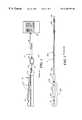
- FIG. 1there is shown a prior art pressure measuring system 100 comprising a guide wire 10 placed within a patient 12 .
- the guide wire 10is used with apparatus 20 that comprises rotary connector assembly 220 and a cable 214 that connects the rotary connector assembly 220 to an interface box 24 .
- Connector 32which is part of the rotary connector assembly 220 electrically interconnects with interface box connector 34 .
- Interface box 24is connected by cable 26 to a pressure monitoring console 28 , such as a WAVEMAPTM pressure monitoring instrument manufactured by EndoSonics, Inc., Collinso Cordova, Calif.
- Console 28can display both proximal and distal pressure measurements as will has controls for calibrating the pressure wire 10 prior to its usage.
- FIG. 2there is shown a more detailed view of the prior art pressure guide wire 10 coupled to a rotary connector assembly 220 .
- pressure guide wire 10can be manufactured utilizing the various constructions as shown and described in U.S. Pat. Nos. 5,163,445, 5,178,159 and 5,240,437.
- Guide wire 10comprises a flexible elongate element 202 having a proximal and distal extremities 204 and 206 and which can be formed of suitable material such as stainless steel.
- the guide wirehaving an outside diameter for example of 0.018 inch or less and having a suitable wall thickness as for example, 0.001′′ to 0.002′′ and conventionally called a “hypotube” having a typical length of approximately 150-170 centimeters.
- a semiconductor pressure sensor 208is located at the distal extremity of guide wire 10 .
- the proximal end of guide wire 10is slid into a rotary connector 210 of the type described in U.S. Pat. Nos. 5,178,159 and 5,348,481 which is part of the rotary connector assembly 220 .
- a torquer 230is typically clipped-on by a physician distal to the rotary connector 210 . Rotation of the torquer 230 causes rotation of guide wire 10 when used in connection with a catherization procedure in a manner well known to those skilled in the art.
- the proximal extremity 204 of the guide wire 10is removably disposed within housing 212 of the type described in U.S. Pat. Nos. 5,178,159, 5,348,481 and 5,358,409. Located close to the distal extremity of guide wire 10 is a pressure sensor 208 which is used to measure pressure within a patient's blood vessels.
- Electrical contacts located within housing 212make electrical contact with electrically conductive sleeves (not shown in FIG. 2) located on the proximal extremity 204 of guide wire 10 .
- the electrical contacts located in housing 212allow for rotation of the guide wire while maintaining electrical contact with the conductive sleeves found in guide wire 10 , these conductive sleeves are electrically coupled to pressure sensor 208 .
- the electrical contacts in housing 212are electrically connected to cable 214 that terminates in connector 32 .
- the connector 32is connected to another mating connector 34 located on the interface box 24 .
- Interface box 24provides signal buffering and voltage level adjustments between guide wire 10 and pressure monitoring console 28 .
- the electrically conductive sleeves 302 , 304 and 306which are located at the proximal extremity of guide wire 10 , are shown in FIG. 3 .
- FIG. 4there is shown an electrical schematic representation of the pressure sensor 208 which comprises two variable resistors 402 and 404 whose resistance values vary with changes in pressure as is known in the art.
- Pressure sensor 208can be a semiconductor having a diaphragm as is well known in the art.
- the two resistors 402 and 404are connected to the three electrically conductive sleeves or bands 302 , 304 and 306 located on the proximal extremity of guide wire 10 as shown.
- FIG. 5shows an exploded isometric view of the prior art rotary connector assembly 220 including rotartary connector 210 and housing 212 .
- the proximal extremity of the flexible elongate member or pressure guide wire 10is inserted into bore 501 with one hand while holding the rotary connector with the other hand.
- the nose piece 503 and the collar 504are then pulled with fingers in a proximal direction against the force of the spring 508 to release the collet 502 and allow it to open.
- the guide wire 10can then enter the bore 501 and pass through the inside of collet 502 and through bearing 510 .
- conductive sleeve 302is making electrical contact with contact member 546
- conductive sleeve 304is making electrical contact with contact member 544
- conductive sleeve 306is making electrical contact with contact member 542 .
- Housing members 514 and 530retain contacts 542 , 544 and 546 .
- a retaining ring 506which is inserted through an opening in bearing 510 , engages with and retains collet 502 .
- Connector 32provides an interconnection with the interface box 24 through a cable as shown in FIG. 1 .
- a problem with the above noted designis that sometimes as the guide wire 10 is being rotated, the contact resistance between electrically conductive sleeves 302 , 304 and 306 located on the guide wire 21 and the corresponding electrical contacts located in housing 212 varies. This contact resistance variation is assumed to be caused by microscopic particles that get lodged between the pressure guide wire's conductive bands 302 , 304 and 306 and the corresponding spring contacts 546 , 544 and 542 . This change in contact resistance causes an error in the pressure measurement as determined by pressure monitoring console 28 , since this change in contact resistance affects the measurement of pressure sensor resistors 402 and 404 .
- FIG. 8An electrically equivalent circuit showing this change in contact resistance is shown in FIG. 8 .
- Pressure sensor 208is shown coupled to sleeve contacts (conductive bands) 302 , 304 and 306 via electrical conductors.
- Sleeve contact 302is shown coupled to contact 546
- sleeve contact 304is shown coupled to contact 544
- sleeve contact 306is shown coupled to contact 542 .
- Variable resistors 802 , 804 and 806represent the variable contact resistance caused by the rotating connector interface. The resistance of resistors 802 , 804 and 806 vary as the pressure guide wire is rotated.
- contact resistance 802is in series with sensor resistor 402 and contact resistance 806 is in series with sensor resistor 404 and thus any change in the contact resistance will affect the measurement of sensor 208 .
- FIG. 1is an illustration showing a prior art guide wire in conjunction with a patient undergoing a catheterization procedure for diagnosis or treatment.
- FIG. 2shows a more detailed view of the prior art guide wire attached to a rotating connector assembly.
- FIG. 3shows the prior art guide wire showing the electrically conductive sleeves located at the proximal extremity of the guide wire.
- FIG. 4shows an electrical representation of the prior art pressure sensor attached to the electrically conductive sleeves.
- FIG. 5shows an exploded view of the prior art rotary connector and housing used to receive the pressure guide wire.
- FIG. 6shows a housing having contacts in accordance with the present invention.
- FIG. 7shows a view of a pressure guide wire in accordance with the invention.
- FIG. 8shows an electrical representation of the prior art electrical interconnection between the guide wire and the rotary connector.
- FIG. 9shows an electrical representation of the electrical interconnection between the guide wire and rotary connector in accordance with the invention.
- FIGS. 10 and 11show electrical schematics for the interface circuit in accordance with the present invention.
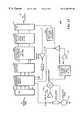
- FIG. 12shows a simplified block diagram of the electrical schematics shown in FIGS. 10 and 11 in accordance with the invention.
- Assembly 600includes first and second housing members 602 and 604 that retain five guide wire spring contacts 606 - 614 .
- Assembly 600takes the place of housing members 514 and 530 and contacts 542 , 544 and 546 in FIG. 5 .
- FIG. 7there is shown a pressure guide wire 700 in accordance with the invention. Similar to guide wire 10 , pressure guide wire 700 includes three conductive sleeves or contacts 702 , 704 and 706 . However, unlike guide wire 10 , the two outer contacts 702 and 706 are wider than the middle contact 704 .
- the wider sleeve contact 702 and 706are designed so that they can make contact with two corresponding contacts each from among contacts 606 - 614 .
- Guide wire sleeve contact 702is designed to make an electrical connection with contacts 606 and 608 and sleeve contact 706 makes electrical connection with contacts 612 and 614 when guide wire 700 is placed in assembly 600 .
- the center guide wire sleeve contact 704makes electrical connection with center contact 610 .
- Housing assembly 600has been designed to be backward compatible and will accept either the newly designed guide wire 700 or the prior art guide wire 10 .
- sleeve contact 306makes connection with contact 612
- sleeve contact 304makes connection with contact 610
- sleeve contact 302makes connection with contact 608 .
- FIG. 9there is shown a simplified electrical representation of the preferred embodiment precision interconnect circuit which solves for the variable contact resistance's and provides for backward compatibility with both the old pressure guide wire 10 and the new pressure wire 700 .
- the pressure sensor 208is coupled to sleeve contacts 702 , 702 ′, 704 , 706 and 706 ′ when a new pressure guide wire 700 is being used.
- contacts 702 ′ and 706 ′are not utilized since the outer sleeve contacts are not as wide as those shown in pressure wire 700 .
- contacts 702 ′ and 706 ′are simply representing the extra wide sleeve contacts found in contacts 702 and 706 as shown in FIG. 7 .
- variable contact resistance problem of the interconnectionis highlighted within box 920 .
- Sleeve contacts 702 ′, 702 , 704 , 706 and 706 ′are coupled to corresponding contacts 614 , 612 , 610 , 608 and 606 in the new design which form the input port for the interconnection circuit.
- contacts 614 and 606are not utilized.
- Switches 910 and 912remain in the open position or first state when a new guide wire 700 is attached and are automatically placed in the closed position or second state when an old guide wire 10 is attached in response to a control signal.
- the control electronics for switches 910 and 912will be discussed in detail further below.
- Switches 910 and 912allow for the interconnect interface to be backward compatible and support both pressure guide wire 10 and the new pressure guide wire 700 .
- new pressure guide wire 700uses a 5-wire interconnection
- the old pressure guide wireuses a 3-wire interconnection.
- a pair of differential operational amplifiers or precision amplifiers 902 and 904 that have high impedance inputs and are part of the interface circuitallow for three low current paths. These paths take away the effect of changes in the contact resistance ( 924 , 926 and 928 ) from changes in the sensor resistors 402 and 404 .
- a reference currentis provided to the sensor resistor 402 and 404 as shown in order to generate the appropriate voltage drops used for pressure change detection.
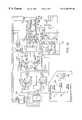
- FIGS. 10 and 11there is shown a full electrical schematic for the interface circuit which replaces the electronics found in interface box 24 .
- the circuitry shown in FIGS. 10 and 11includes not only the circuitry needed to perform the precision interconnection as described above, but also provides the necessary signal conditioning circuitry needed to match the signal from the pressure sensor 208 to the pressure measurement console 28 .
- the signal conditioning circuitrywill not be discussed in detail since it is not needed in the understanding of the present invention.
- the circuit shown in FIG. 10is the mother board and the circuit shown in FIG. 11 is a daughter board which in the preferred embodiment comprise two separate printed circuit boards which are coupled together.
- the two circuit boardsare coupled together using jack connectors J 1 and J 2 found in the circuit of FIG. 10 which mate with corresponding plug connectors P 1 and P 2 located on the circuit of FIG. 11 .
- Connector “JP2” 1002 in FIG. 10is coupled to the pressure sensor resistors 402 and 404 which are coupled through via connectors 32 and 34 into the interface circuitry.
- the five sensor contactsare coupled to pins 2 , 4 , 6 , 8 and 10 of connector JP2 as shown in diagram 1014 .
- Differential amplifiers 902 and 904 as previously shown in FIG. 9 that are part of amplifier stage 1008provide a gain of approximately two.
- the output of these amplifiersare fed into a 2 pole, 250 Hertz low pass filter (LPF) stage 1012 which provides for a gain of approximately twenty.
- the outputs of the LPF stage 1012are coupled to connector “JP1” 1010 that in turn couples into the pressure monitoring console 28 .
- LPFHertz low pass filter
- Pins 7 and 9 of connector JP1are inputs to the pressure monitoring console, while pins 1 , 2 , 4 , 6 , 8 , 10 , 14 , 15 and 16 are signals coming from the pressure console 28 into the interface circuitry.
- circuit block 1004provides offset voltage correction for the interface between the pressure guide wire 700 and the pressure monitoring console 24 .
- Box 1016shows the internal interconnections of connector J 2 .
- operational amplifiers U 5 A, U 1 A and U 1 Bform a buffer stage 1108 that provides signal buffering.
- Block 1104forms an oscillator circuit that provides a signal of about 10-12 kilohertz. This signal is used to determine whether an old pressure guide wire 10 or a new pressure guide wire 700 is coupled to the interface circuitry in accordance with the present invention.
- a synchronous demodulator circuit 1102takes the oscillating signals and provides a control signal 1106 that is used to control switches 910 and 912 . Switches 910 and 912 remain open when pressure sensor 700 is attached and are closed when pressure wire 10 is attached.
- the output of demodulator circuit 1102passes through a two pole 30 Hertz low pass filter stage 1112 having a gain of approximately thirty.
- FIG. 12shows a simplified block diagram of the electrical schematics of FIGS. 11 and 12 as interface circuit 1200 .
- Pressure wire 700is coupled to connector 1002 that is in turn coupled to the interface switch circuit 1110 comprising the two digital switches 910 and 912 .
- the output of the digital switchesis passed through a buffer stage 1108 prior to being sent to the differential amplifier stage 1008 comprising differential amplifiers 902 and 904 .
- the output of the differential amplifier stage 1008is sent to the 2 pole 250 Hertz low pass filter stage 1012 before the signals are sent to console 28 .
- a reference voltage generator stage 1202provides the necessary voltages to the circuit.
- an oscillator 1104 and demodulator 1102are used to provide a control signal 1106 which either closes switches 910 and 912 or leaves them in the open position.
- the control signal 1106leaves the switches 910 and 912 in the open state, while if the old pressure wire 10 is detected control signal 1106 causes the switches to go to the closed state.
- a high frequency (10-12 Kilohertz) signalhaving low amplitude to make the switching determination between the 3-wire and 5-wire guide wires, prevents any stray noise and interference from affecting the control signal.
- the use of such a low amplitude-oscillating signalprevents the signal from affecting the measurement of pressure sensor resistors 402 and 404 .
- a large signal at capacitor C 2causes control signal 1106 at the output of inverter 114 to be logic high closing the switches 910 and 912 indicating a 3-wire pressure wire 10 is connected to the interface circuit. While a low signal at capacitor C 2 caused by the connection of a 5-wire pressure wire 700 causes the control signal 1106 to be at a low logic level leaving switches 910 and 912 in the open position.
- the present inventionwith its use of high input impedance differential amplifiers 902 and 904 to measure pressure sensor resistors 402 and 404 avoids the problem caused by changing contact resistance 922 - 930 . Also, the automatic switching technique disclosed above provides for a system which is backward compatible between pressure guide wires 10 and 700 .
- the present inventionis not so limited and can be used for non-rotating connections.
- the present inventioncan be used for not only with a pressure guide wire it can be used with other devices that need proper measurement of electrical parameters from the device.
- the present inventioncan be used to provide a precision interconnect for devices having any number of resistors. If the number of resistors that need to be monitored change, a change has also to be made as to the number of monitoring devices such as differential op-amps 902 and 904 need to be used.
Landscapes
- Health & Medical Sciences (AREA)
- Life Sciences & Earth Sciences (AREA)
- Cardiology (AREA)
- Heart & Thoracic Surgery (AREA)
- Molecular Biology (AREA)
- Physiology (AREA)
- Biophysics (AREA)
- Pathology (AREA)
- Engineering & Computer Science (AREA)
- Biomedical Technology (AREA)
- Vascular Medicine (AREA)
- Medical Informatics (AREA)
- Physics & Mathematics (AREA)
- Surgery (AREA)
- Animal Behavior & Ethology (AREA)
- General Health & Medical Sciences (AREA)
- Public Health (AREA)
- Veterinary Medicine (AREA)
- Measuring Pulse, Heart Rate, Blood Pressure Or Blood Flow (AREA)
- Measuring Fluid Pressure (AREA)
Abstract
Description
Claims (22)
Priority Applications (5)
| Application Number | Priority Date | Filing Date | Title |
|---|---|---|---|
| US09/392,372US6265792B1 (en) | 1999-09-08 | 1999-09-08 | Medical device having precision interconnect |
| EP00974077AEP1221170A4 (en) | 1999-09-08 | 2000-09-07 | Medical device having precision interconnect |
| JP2001522562AJP2003509092A (en) | 1999-09-08 | 2000-09-07 | Medical devices with precision interconnect devices |
| CA002384160ACA2384160A1 (en) | 1999-09-08 | 2000-09-07 | Medical device having precision interconnect |
| PCT/US2000/040840WO2001018835A1 (en) | 1999-09-08 | 2000-09-07 | Medical device having precision interconnect |
Applications Claiming Priority (1)
| Application Number | Priority Date | Filing Date | Title |
|---|---|---|---|
| US09/392,372US6265792B1 (en) | 1999-09-08 | 1999-09-08 | Medical device having precision interconnect |
Publications (1)
| Publication Number | Publication Date |
|---|---|
| US6265792B1true US6265792B1 (en) | 2001-07-24 |
Family
ID=23550315
Family Applications (1)
| Application Number | Title | Priority Date | Filing Date |
|---|---|---|---|
| US09/392,372Expired - LifetimeUS6265792B1 (en) | 1999-09-08 | 1999-09-08 | Medical device having precision interconnect |
Country Status (5)
| Country | Link |
|---|---|
| US (1) | US6265792B1 (en) |
| EP (1) | EP1221170A4 (en) |
| JP (1) | JP2003509092A (en) |
| CA (1) | CA2384160A1 (en) |
| WO (1) | WO2001018835A1 (en) |
Cited By (51)
| Publication number | Priority date | Publication date | Assignee | Title |
|---|---|---|---|---|
| US6585660B2 (en) | 2001-05-18 | 2003-07-01 | Jomed Inc. | Signal conditioning device for interfacing intravascular sensors having varying operational characteristics to a physiology monitor |
| US20030216621A1 (en)* | 2002-05-20 | 2003-11-20 | Jomed N.V. | Multipurpose host system for invasive cardiovascular diagnostic measurement acquisition and display |
| US6663570B2 (en) | 2002-02-27 | 2003-12-16 | Volcano Therapeutics, Inc. | Connector for interfacing intravascular sensors to a physiology monitor |
| US20080062157A1 (en)* | 2003-02-20 | 2008-03-13 | Planar Systems, Inc. | Light sensitive display |
| US20080161696A1 (en)* | 2006-11-08 | 2008-07-03 | Lightlab Imaging, Inc. | Opto-acoustic imaging devices and methods |
| US8289429B2 (en) | 2004-04-16 | 2012-10-16 | Apple Inc. | Image sensor with photosensitive thin film transistors and dark current compensation |
| US8441422B2 (en) | 2002-02-20 | 2013-05-14 | Apple Inc. | Light sensitive display with object detection calibration |
| US8638320B2 (en) | 2011-06-22 | 2014-01-28 | Apple Inc. | Stylus orientation detection |
| US8928635B2 (en) | 2011-06-22 | 2015-01-06 | Apple Inc. | Active stylus |
| US9134851B2 (en) | 2002-02-20 | 2015-09-15 | Apple Inc. | Light sensitive display |
| US9176604B2 (en) | 2012-07-27 | 2015-11-03 | Apple Inc. | Stylus device |
| US9310923B2 (en) | 2010-12-03 | 2016-04-12 | Apple Inc. | Input device for touch sensitive devices |
| US9329703B2 (en) | 2011-06-22 | 2016-05-03 | Apple Inc. | Intelligent stylus |
| US9354735B2 (en) | 2002-05-23 | 2016-05-31 | Apple Inc. | Light sensitive display |
| US9429713B2 (en) | 2014-04-17 | 2016-08-30 | Boston Scientific Scimed, Inc. | Self-cleaning optical connector |
| US9557845B2 (en) | 2012-07-27 | 2017-01-31 | Apple Inc. | Input device for and method of communication with capacitive devices through frequency variation |
| US9652090B2 (en) | 2012-07-27 | 2017-05-16 | Apple Inc. | Device for digital communication through capacitive coupling |
| US9775523B2 (en) | 2013-10-14 | 2017-10-03 | Boston Scientific Scimed, Inc. | Pressure sensing guidewire and methods for calculating fractional flow reserve |
| US9782129B2 (en) | 2014-08-01 | 2017-10-10 | Boston Scientific Scimed, Inc. | Pressure sensing guidewires |
| US9795307B2 (en) | 2014-12-05 | 2017-10-24 | Boston Scientific Scimed, Inc. | Pressure sensing guidewires |
| US9833221B2 (en) | 2013-03-15 | 2017-12-05 | Lightlab Imaging, Inc. | Apparatus and method of image registration |
| US9939935B2 (en) | 2013-07-31 | 2018-04-10 | Apple Inc. | Scan engine for touch controller architecture |
| US10028666B2 (en) | 2013-03-15 | 2018-07-24 | Boston Scientific Scimed, Inc. | Pressure sensing guidewire |
| US10048775B2 (en) | 2013-03-14 | 2018-08-14 | Apple Inc. | Stylus detection and demodulation |
| US10061450B2 (en) | 2014-12-04 | 2018-08-28 | Apple Inc. | Coarse scan and targeted active mode scan for touch |
| US10258240B1 (en) | 2014-11-24 | 2019-04-16 | Vascular Imaging Corporation | Optical fiber pressure sensor |
| US10278594B2 (en) | 2014-06-04 | 2019-05-07 | Boston Scientific Scimed, Inc. | Pressure sensing guidewire systems with reduced pressure offsets |
| US10327645B2 (en) | 2013-10-04 | 2019-06-25 | Vascular Imaging Corporation | Imaging techniques using an imaging guidewire |
| US10474277B2 (en) | 2016-05-31 | 2019-11-12 | Apple Inc. | Position-based stylus communication |
| US10499820B2 (en) | 2013-05-22 | 2019-12-10 | Boston Scientific Scimed, Inc. | Pressure sensing guidewire systems including an optical connector cable |
| US10506934B2 (en) | 2012-05-25 | 2019-12-17 | Phyzhon Health Inc. | Optical fiber pressure sensor |
| US10537255B2 (en) | 2013-11-21 | 2020-01-21 | Phyzhon Health Inc. | Optical fiber pressure sensor |
| US10582860B2 (en) | 2012-08-27 | 2020-03-10 | Boston Scientific Scimed, Inc. | Pressure-sensing medical devices and medical device systems |
| US10702170B2 (en) | 2013-07-01 | 2020-07-07 | Zurich Medical Corporation | Apparatus and method for intravascular measurements |
| US10702162B2 (en) | 2010-11-09 | 2020-07-07 | Opsens Inc. | Guidewire with internal pressure sensor |
| US10792012B2 (en) | 2012-11-19 | 2020-10-06 | Lightlab Imaging, Inc. | Interface devices, systems and methods for multimodal probes |
| US10835183B2 (en) | 2013-07-01 | 2020-11-17 | Zurich Medical Corporation | Apparatus and method for intravascular measurements |
| US10835182B2 (en) | 2013-08-14 | 2020-11-17 | Boston Scientific Scimed, Inc. | Medical device systems including an optical fiber with a tapered core |
| US10888232B2 (en) | 2011-08-20 | 2021-01-12 | Philips Image Guided Therapy Corporation | Devices, systems, and methods for assessing a vessel |
| US10932679B2 (en) | 2014-03-18 | 2021-03-02 | Boston Scientific Scimed, Inc. | Pressure sensing guidewires and methods of use |
| US11058307B2 (en) | 2016-02-23 | 2021-07-13 | Boston Scientific Scimed, Inc. | Pressure sensing guidewire systems including an optical connector cable |
| US11076765B2 (en) | 2013-07-26 | 2021-08-03 | Boston Scientific Scimed, Inc. | FFR sensor head design that minimizes stress induced pressure offsets |
| US11122980B2 (en) | 2011-08-20 | 2021-09-21 | Imperial College Of Science, Technology And Medicine | Devices, systems, and methods for visually depicting a vessel and evaluating treatment options |
| US11311196B2 (en) | 2018-02-23 | 2022-04-26 | Boston Scientific Scimed, Inc. | Methods for assessing a vessel with sequential physiological measurements |
| US11452451B2 (en)* | 2009-09-18 | 2022-09-27 | St. Jude Medical Coordination Center Bvba | Device for acquiring physiological variables measured in a body |
| US11559213B2 (en) | 2018-04-06 | 2023-01-24 | Boston Scientific Scimed, Inc. | Medical device with pressure sensor |
| US11564581B2 (en) | 2017-08-03 | 2023-01-31 | Boston Scientific Scimed, Inc. | Methods for assessing fractional flow reserve |
| US11666232B2 (en) | 2018-04-18 | 2023-06-06 | Boston Scientific Scimed, Inc. | Methods for assessing a vessel with sequential physiological measurements |
| US11850073B2 (en) | 2018-03-23 | 2023-12-26 | Boston Scientific Scimed, Inc. | Medical device with pressure sensor |
| US12087000B2 (en) | 2021-03-05 | 2024-09-10 | Boston Scientific Scimed, Inc. | Systems and methods for vascular image co-registration |
| US12153764B1 (en) | 2020-09-25 | 2024-11-26 | Apple Inc. | Stylus with receive architecture for position determination |
Families Citing this family (2)
| Publication number | Priority date | Publication date | Assignee | Title |
|---|---|---|---|---|
| US7946997B2 (en)* | 2007-02-16 | 2011-05-24 | Radi Medical Systems Ab | Measurement system to measure a physiological condition in a body |
| DE102007009573A1 (en)* | 2007-02-27 | 2008-09-04 | Up Management Gmbh & Co Med-Systems Kg | One-way sensor unit for patient observation, and arterial blood pressure sensor unit, has sensor provided around electrical quantity, which is based on quantity that has to be determined, and signal terminal that is provided around outlet |
Citations (13)
| Publication number | Priority date | Publication date | Assignee | Title |
|---|---|---|---|---|
| US4366714A (en) | 1979-01-08 | 1983-01-04 | Cise S.P.A. | Pressure/temperature probe |
| US5163445A (en) | 1987-04-10 | 1992-11-17 | Cardiometrics, Inc. | Apparatus, system and method for measuring spatial average velocity and/or volumetric flow of blood in a vessel and screw joint for use therewith |
| US5178159A (en) | 1988-11-02 | 1993-01-12 | Cardiometrics, Inc. | Torqueable guide wire assembly with electrical functions, male and female connectors rotatable with respect to one another |
| US5240437A (en) | 1988-11-02 | 1993-08-31 | Cardiometrics, Inc. | Torqueable guide wire assembly with electrical functions, male and female connectors for use therewith and system and apparatus for utilizing the same |
| US5348481A (en) | 1993-09-29 | 1994-09-20 | Cardiometrics, Inc. | Rotary connector for use with small diameter flexible elongate member having electrical capabilities |
| US5375596A (en)* | 1992-09-29 | 1994-12-27 | Hdc Corporation | Method and apparatus for determining the position of catheters, tubes, placement guidewires and implantable ports within biological tissue |
| US5384540A (en)* | 1991-11-12 | 1995-01-24 | Molex Incorporated | Wire presence and identification system |
| US5520644A (en)* | 1991-11-18 | 1996-05-28 | Intelliwire, Inc. | Flexible elongate device having steerable distal extremity and apparatus for use therewith and method |
| US5666958A (en)* | 1995-04-06 | 1997-09-16 | Rothenberg; Peter M. | Interface module for electrically connecting medical equipment |
| US5715827A (en) | 1994-09-02 | 1998-02-10 | Cardiometrics, Inc. | Ultra miniature pressure sensor and guide wire using the same and method |
| US5792194A (en)* | 1995-09-29 | 1998-08-11 | Medico Spa | Transvalvular impedence measurement |
| US5903971A (en)* | 1996-11-22 | 1999-05-18 | Molex Incorporated | Wire termination apparatus for making wire harnesses |
| US5935079A (en)* | 1994-03-31 | 1999-08-10 | Ep Technologies, Inc. | Systems and methods for positioning multiple electrode structures in electrical contact with the myocardium |
Family Cites Families (5)
| Publication number | Priority date | Publication date | Assignee | Title |
|---|---|---|---|---|
| US4446715A (en)* | 1982-06-07 | 1984-05-08 | Camino Laboratories, Inc. | Transducer calibration system |
| US5193547A (en)* | 1984-07-16 | 1993-03-16 | Evans Ii George D | Universal connector means for transducer/monitor systems |
| US5358409A (en) | 1993-08-31 | 1994-10-25 | Cardiometrics, Inc. | Rotary connector for flexible elongate member having electrical properties |
| US5645059A (en)* | 1993-12-17 | 1997-07-08 | Nellcor Incorporated | Medical sensor with modulated encoding scheme |
| US5807247A (en)* | 1995-12-20 | 1998-09-15 | Nellcor Puritan Bennett Incorporated | Method and apparatus for facilitating compatibility between pulse oximeters and sensor probes |
- 1999
- 1999-09-08USUS09/392,372patent/US6265792B1/ennot_activeExpired - Lifetime
- 2000
- 2000-09-07WOPCT/US2000/040840patent/WO2001018835A1/enactiveApplication Filing
- 2000-09-07JPJP2001522562Apatent/JP2003509092A/enactivePending
- 2000-09-07EPEP00974077Apatent/EP1221170A4/ennot_activeWithdrawn
- 2000-09-07CACA002384160Apatent/CA2384160A1/ennot_activeAbandoned
Patent Citations (13)
| Publication number | Priority date | Publication date | Assignee | Title |
|---|---|---|---|---|
| US4366714A (en) | 1979-01-08 | 1983-01-04 | Cise S.P.A. | Pressure/temperature probe |
| US5163445A (en) | 1987-04-10 | 1992-11-17 | Cardiometrics, Inc. | Apparatus, system and method for measuring spatial average velocity and/or volumetric flow of blood in a vessel and screw joint for use therewith |
| US5178159A (en) | 1988-11-02 | 1993-01-12 | Cardiometrics, Inc. | Torqueable guide wire assembly with electrical functions, male and female connectors rotatable with respect to one another |
| US5240437A (en) | 1988-11-02 | 1993-08-31 | Cardiometrics, Inc. | Torqueable guide wire assembly with electrical functions, male and female connectors for use therewith and system and apparatus for utilizing the same |
| US5384540A (en)* | 1991-11-12 | 1995-01-24 | Molex Incorporated | Wire presence and identification system |
| US5520644A (en)* | 1991-11-18 | 1996-05-28 | Intelliwire, Inc. | Flexible elongate device having steerable distal extremity and apparatus for use therewith and method |
| US5375596A (en)* | 1992-09-29 | 1994-12-27 | Hdc Corporation | Method and apparatus for determining the position of catheters, tubes, placement guidewires and implantable ports within biological tissue |
| US5348481A (en) | 1993-09-29 | 1994-09-20 | Cardiometrics, Inc. | Rotary connector for use with small diameter flexible elongate member having electrical capabilities |
| US5935079A (en)* | 1994-03-31 | 1999-08-10 | Ep Technologies, Inc. | Systems and methods for positioning multiple electrode structures in electrical contact with the myocardium |
| US5715827A (en) | 1994-09-02 | 1998-02-10 | Cardiometrics, Inc. | Ultra miniature pressure sensor and guide wire using the same and method |
| US5666958A (en)* | 1995-04-06 | 1997-09-16 | Rothenberg; Peter M. | Interface module for electrically connecting medical equipment |
| US5792194A (en)* | 1995-09-29 | 1998-08-11 | Medico Spa | Transvalvular impedence measurement |
| US5903971A (en)* | 1996-11-22 | 1999-05-18 | Molex Incorporated | Wire termination apparatus for making wire harnesses |
Non-Patent Citations (1)
| Title |
|---|
| Frank M.L. Van Der Goes and Gerard C.M. Meijer, "A Universal Transducer Interface for Capacitive and Resistive Sensor Elements". |
Cited By (89)
| Publication number | Priority date | Publication date | Assignee | Title |
|---|---|---|---|---|
| US6585660B2 (en) | 2001-05-18 | 2003-07-01 | Jomed Inc. | Signal conditioning device for interfacing intravascular sensors having varying operational characteristics to a physiology monitor |
| US9971456B2 (en) | 2002-02-20 | 2018-05-15 | Apple Inc. | Light sensitive display with switchable detection modes for detecting a fingerprint |
| US9134851B2 (en) | 2002-02-20 | 2015-09-15 | Apple Inc. | Light sensitive display |
| US9411470B2 (en) | 2002-02-20 | 2016-08-09 | Apple Inc. | Light sensitive display with multiple data set object detection |
| US8570449B2 (en) | 2002-02-20 | 2013-10-29 | Apple Inc. | Light sensitive display with pressure sensor |
| US8441422B2 (en) | 2002-02-20 | 2013-05-14 | Apple Inc. | Light sensitive display with object detection calibration |
| US11073926B2 (en) | 2002-02-20 | 2021-07-27 | Apple Inc. | Light sensitive display |
| US7274956B2 (en) | 2002-02-27 | 2007-09-25 | Volcano Corporation | Connector for interfacing intravascular sensors to a physiology monitor |
| US6663570B2 (en) | 2002-02-27 | 2003-12-16 | Volcano Therapeutics, Inc. | Connector for interfacing intravascular sensors to a physiology monitor |
| US20040082866A1 (en)* | 2002-02-27 | 2004-04-29 | Mott Eric V. | Connector for interfacing intravascular sensors to a physiology monitor |
| US20070060822A1 (en)* | 2002-05-20 | 2007-03-15 | Volcano Corp. | Multipurpose host system for invasive cardiovascular diagnostic measurement acquisition and display |
| US20030216621A1 (en)* | 2002-05-20 | 2003-11-20 | Jomed N.V. | Multipurpose host system for invasive cardiovascular diagnostic measurement acquisition and display |
| US8556820B2 (en) | 2002-05-20 | 2013-10-15 | Volcano Corporation | Multipurpose host system for invasive cardiovascular diagnostic measurement acquisition and display |
| US8562537B2 (en) | 2002-05-20 | 2013-10-22 | Volcano Corporation | Multipurpose host system for invasive cardiovascular diagnostic measurement acquisition and display |
| US7134994B2 (en) | 2002-05-20 | 2006-11-14 | Volcano Corporation | Multipurpose host system for invasive cardiovascular diagnostic measurement acquisition and display |
| US8636659B2 (en) | 2002-05-20 | 2014-01-28 | Volcano Corporation | Multipurpose host system for invasive cardiovascular diagnostic measurement acquisition and display |
| US9354735B2 (en) | 2002-05-23 | 2016-05-31 | Apple Inc. | Light sensitive display |
| US20080062157A1 (en)* | 2003-02-20 | 2008-03-13 | Planar Systems, Inc. | Light sensitive display |
| US8289429B2 (en) | 2004-04-16 | 2012-10-16 | Apple Inc. | Image sensor with photosensitive thin film transistors and dark current compensation |
| US20080161696A1 (en)* | 2006-11-08 | 2008-07-03 | Lightlab Imaging, Inc. | Opto-acoustic imaging devices and methods |
| US7935060B2 (en) | 2006-11-08 | 2011-05-03 | Lightlab Imaging, Inc. | Opto-acoustic imaging devices and methods |
| US8449468B2 (en) | 2006-11-08 | 2013-05-28 | Lightlab Imaging, Inc. | Opto-acoustic imaging devices and methods |
| US8753281B2 (en) | 2006-11-08 | 2014-06-17 | Lightlab Imaging Inc. | Opto-acoustic imaging devices and methods |
| US11452451B2 (en)* | 2009-09-18 | 2022-09-27 | St. Jude Medical Coordination Center Bvba | Device for acquiring physiological variables measured in a body |
| US12138009B2 (en) | 2009-09-18 | 2024-11-12 | St. Jude Medical Coordination Center Bvba | Device for acquiring physiological variables measured in a body |
| US11786130B2 (en) | 2010-11-09 | 2023-10-17 | Opsens Inc. | Guidewire with internal pressure sensor |
| US10750949B2 (en) | 2010-11-09 | 2020-08-25 | Opsens Inc. | Guidewire with internal pressure sensor |
| US10702162B2 (en) | 2010-11-09 | 2020-07-07 | Opsens Inc. | Guidewire with internal pressure sensor |
| US9310923B2 (en) | 2010-12-03 | 2016-04-12 | Apple Inc. | Input device for touch sensitive devices |
| US8928635B2 (en) | 2011-06-22 | 2015-01-06 | Apple Inc. | Active stylus |
| US9519361B2 (en) | 2011-06-22 | 2016-12-13 | Apple Inc. | Active stylus |
| US8638320B2 (en) | 2011-06-22 | 2014-01-28 | Apple Inc. | Stylus orientation detection |
| US9329703B2 (en) | 2011-06-22 | 2016-05-03 | Apple Inc. | Intelligent stylus |
| US9921684B2 (en) | 2011-06-22 | 2018-03-20 | Apple Inc. | Intelligent stylus |
| US11122980B2 (en) | 2011-08-20 | 2021-09-21 | Imperial College Of Science, Technology And Medicine | Devices, systems, and methods for visually depicting a vessel and evaluating treatment options |
| US10888232B2 (en) | 2011-08-20 | 2021-01-12 | Philips Image Guided Therapy Corporation | Devices, systems, and methods for assessing a vessel |
| US10506934B2 (en) | 2012-05-25 | 2019-12-17 | Phyzhon Health Inc. | Optical fiber pressure sensor |
| US11172833B2 (en) | 2012-05-25 | 2021-11-16 | Phyzhon Health Inc. | Optical fiber pressure sensor guidewire |
| US9557845B2 (en) | 2012-07-27 | 2017-01-31 | Apple Inc. | Input device for and method of communication with capacitive devices through frequency variation |
| US9652090B2 (en) | 2012-07-27 | 2017-05-16 | Apple Inc. | Device for digital communication through capacitive coupling |
| US9176604B2 (en) | 2012-07-27 | 2015-11-03 | Apple Inc. | Stylus device |
| US9582105B2 (en) | 2012-07-27 | 2017-02-28 | Apple Inc. | Input device for touch sensitive devices |
| US10582860B2 (en) | 2012-08-27 | 2020-03-10 | Boston Scientific Scimed, Inc. | Pressure-sensing medical devices and medical device systems |
| US12127881B2 (en) | 2012-11-19 | 2024-10-29 | Lightlab Imaging, Inc. | Interface devices, systems and methods for multimodal probes |
| US11701089B2 (en) | 2012-11-19 | 2023-07-18 | Lightlab Imaging, Inc. | Multimodal imaging systems, probes and methods |
| US12127882B2 (en) | 2012-11-19 | 2024-10-29 | Lightlab Imaging, Inc. | Multimodal imaging systems probes and methods |
| US10792012B2 (en) | 2012-11-19 | 2020-10-06 | Lightlab Imaging, Inc. | Interface devices, systems and methods for multimodal probes |
| US10048775B2 (en) | 2013-03-14 | 2018-08-14 | Apple Inc. | Stylus detection and demodulation |
| US10028666B2 (en) | 2013-03-15 | 2018-07-24 | Boston Scientific Scimed, Inc. | Pressure sensing guidewire |
| US9833221B2 (en) | 2013-03-15 | 2017-12-05 | Lightlab Imaging, Inc. | Apparatus and method of image registration |
| US10499820B2 (en) | 2013-05-22 | 2019-12-10 | Boston Scientific Scimed, Inc. | Pressure sensing guidewire systems including an optical connector cable |
| US10835183B2 (en) | 2013-07-01 | 2020-11-17 | Zurich Medical Corporation | Apparatus and method for intravascular measurements |
| US11471061B2 (en) | 2013-07-01 | 2022-10-18 | Zurich Medical Corporation | Apparatus and method for intravascular measurements |
| US10702170B2 (en) | 2013-07-01 | 2020-07-07 | Zurich Medical Corporation | Apparatus and method for intravascular measurements |
| US11076765B2 (en) | 2013-07-26 | 2021-08-03 | Boston Scientific Scimed, Inc. | FFR sensor head design that minimizes stress induced pressure offsets |
| US10067580B2 (en) | 2013-07-31 | 2018-09-04 | Apple Inc. | Active stylus for use with touch controller architecture |
| US9939935B2 (en) | 2013-07-31 | 2018-04-10 | Apple Inc. | Scan engine for touch controller architecture |
| US12340048B2 (en) | 2013-07-31 | 2025-06-24 | Apple Inc. | Touch controller architecture |
| US10845901B2 (en) | 2013-07-31 | 2020-11-24 | Apple Inc. | Touch controller architecture |
| US11687192B2 (en) | 2013-07-31 | 2023-06-27 | Apple Inc. | Touch controller architecture |
| US10835182B2 (en) | 2013-08-14 | 2020-11-17 | Boston Scientific Scimed, Inc. | Medical device systems including an optical fiber with a tapered core |
| US10327645B2 (en) | 2013-10-04 | 2019-06-25 | Vascular Imaging Corporation | Imaging techniques using an imaging guidewire |
| US11298026B2 (en) | 2013-10-04 | 2022-04-12 | Phyzhon Health Inc. | Imaging techniques using an imaging guidewire |
| US10499817B2 (en) | 2013-10-14 | 2019-12-10 | Boston Scientific Scimed, Inc. | Pressure sensing guidewire and methods for calculating fractional flow reserve |
| US9775523B2 (en) | 2013-10-14 | 2017-10-03 | Boston Scientific Scimed, Inc. | Pressure sensing guidewire and methods for calculating fractional flow reserve |
| US10537255B2 (en) | 2013-11-21 | 2020-01-21 | Phyzhon Health Inc. | Optical fiber pressure sensor |
| US11696692B2 (en) | 2013-11-21 | 2023-07-11 | Phyzhon Health Inc. | Optical fiber pressure sensor |
| US10932679B2 (en) | 2014-03-18 | 2021-03-02 | Boston Scientific Scimed, Inc. | Pressure sensing guidewires and methods of use |
| US9563023B2 (en) | 2014-04-17 | 2017-02-07 | Boston Scientific Scimed, Inc. | Self-cleaning optical connector |
| US9429713B2 (en) | 2014-04-17 | 2016-08-30 | Boston Scientific Scimed, Inc. | Self-cleaning optical connector |
| US10278594B2 (en) | 2014-06-04 | 2019-05-07 | Boston Scientific Scimed, Inc. | Pressure sensing guidewire systems with reduced pressure offsets |
| US9782129B2 (en) | 2014-08-01 | 2017-10-10 | Boston Scientific Scimed, Inc. | Pressure sensing guidewires |
| US10258240B1 (en) | 2014-11-24 | 2019-04-16 | Vascular Imaging Corporation | Optical fiber pressure sensor |
| US10061450B2 (en) | 2014-12-04 | 2018-08-28 | Apple Inc. | Coarse scan and targeted active mode scan for touch |
| US10061449B2 (en) | 2014-12-04 | 2018-08-28 | Apple Inc. | Coarse scan and targeted active mode scan for touch and stylus |
| US10067618B2 (en) | 2014-12-04 | 2018-09-04 | Apple Inc. | Coarse scan and targeted active mode scan for touch |
| US10664113B2 (en) | 2014-12-04 | 2020-05-26 | Apple Inc. | Coarse scan and targeted active mode scan for touch and stylus |
| US9795307B2 (en) | 2014-12-05 | 2017-10-24 | Boston Scientific Scimed, Inc. | Pressure sensing guidewires |
| US11058307B2 (en) | 2016-02-23 | 2021-07-13 | Boston Scientific Scimed, Inc. | Pressure sensing guidewire systems including an optical connector cable |
| US10474277B2 (en) | 2016-05-31 | 2019-11-12 | Apple Inc. | Position-based stylus communication |
| US11564581B2 (en) | 2017-08-03 | 2023-01-31 | Boston Scientific Scimed, Inc. | Methods for assessing fractional flow reserve |
| US11311196B2 (en) | 2018-02-23 | 2022-04-26 | Boston Scientific Scimed, Inc. | Methods for assessing a vessel with sequential physiological measurements |
| US12369800B2 (en) | 2018-02-23 | 2025-07-29 | Boston Scientific Scimed, Inc. | Methods for assessing a vessel with sequential physiological measurements |
| US11850073B2 (en) | 2018-03-23 | 2023-12-26 | Boston Scientific Scimed, Inc. | Medical device with pressure sensor |
| US11559213B2 (en) | 2018-04-06 | 2023-01-24 | Boston Scientific Scimed, Inc. | Medical device with pressure sensor |
| US11666232B2 (en) | 2018-04-18 | 2023-06-06 | Boston Scientific Scimed, Inc. | Methods for assessing a vessel with sequential physiological measurements |
| US12268482B2 (en) | 2018-04-18 | 2025-04-08 | Boston Scientific Scimed, Inc. | Methods for assessing a vessel with sequential physiological measurements |
| US12153764B1 (en) | 2020-09-25 | 2024-11-26 | Apple Inc. | Stylus with receive architecture for position determination |
| US12087000B2 (en) | 2021-03-05 | 2024-09-10 | Boston Scientific Scimed, Inc. | Systems and methods for vascular image co-registration |
Also Published As
| Publication number | Publication date |
|---|---|
| CA2384160A1 (en) | 2001-03-15 |
| JP2003509092A (en) | 2003-03-11 |
| EP1221170A1 (en) | 2002-07-10 |
| WO2001018835A1 (en) | 2001-03-15 |
| EP1221170A4 (en) | 2009-01-21 |
Similar Documents
| Publication | Publication Date | Title |
|---|---|---|
| US6265792B1 (en) | Medical device having precision interconnect | |
| US11452451B2 (en) | Device for acquiring physiological variables measured in a body | |
| JP5102185B2 (en) | Signal conditioning device for interfacing an intravascular sensor with variable operating characteristics to a physiological monitor | |
| US6615067B2 (en) | Method and device for measuring physical characteristics in a body | |
| EP2638862B1 (en) | Improved combination sensor guidewire and methods of use | |
| US6663570B2 (en) | Connector for interfacing intravascular sensors to a physiology monitor | |
| AU596391B2 (en) | Method of testing epithelial tissue | |
| US5092339A (en) | Method and apparatus for electrically compensated measurement of cardiac output | |
| US5991355A (en) | Device for counting the number of uses of a sensor | |
| US7967761B2 (en) | Sensor and guide wire assembly | |
| AU2009202758B2 (en) | Shielding of catheter handle | |
| US8187195B2 (en) | Sensor wire assembly | |
| EP3099226B1 (en) | Luminal impedance device with integrated circuit modules | |
| EP1658808A1 (en) | Microminiature pressure sensor and guidewire using the same | |
| JP2015501193A (en) | System and method for wireless vascular pressure measuring device | |
| JP6290250B2 (en) | Pressure sensing endovascular device, system, and method | |
| US7326088B2 (en) | Reducing leakage current in guide wire assembly | |
| AU2010297345B2 (en) | Eavesdropping device | |
| EP1774905B1 (en) | Sensor wire assembly | |
| EP1136032B1 (en) | A device for measuring physical variables in a living body | |
| EP2967341B1 (en) | A cable and related method for connecting a receiver in wireless communication with sensor equipment and a physiological monitor | |
| JP4473375B2 (en) | Site coding device for medical device introduced into patient body | |
| JP2006136723A (en) | Method and device for reducing leakage current in guide wire assembly |
Legal Events
| Date | Code | Title | Description |
|---|---|---|---|
| AS | Assignment | Owner name:ENDOSONICS CORPORATION, CALIFORNIA Free format text:ASSIGNMENT OF ASSIGNORS INTEREST;ASSIGNOR:GRANCHUKOFF, PETER I.;REEL/FRAME:010235/0205 Effective date:19990903 | |
| FEPP | Fee payment procedure | Free format text:PAT HOLDER NO LONGER CLAIMS SMALL ENTITY STATUS, ENTITY STATUS SET TO UNDISCOUNTED (ORIGINAL EVENT CODE: STOL); ENTITY STATUS OF PATENT OWNER: SMALL ENTITY | |
| STCF | Information on status: patent grant | Free format text:PATENTED CASE | |
| AS | Assignment | Owner name:JOMED INC., CALIFORNIA Free format text:CHANGE OF NAME;ASSIGNOR:ENDOSONICS CORPORATION;REEL/FRAME:012884/0106 Effective date:20001122 | |
| AS | Assignment | Owner name:VOLCANO THERAPEUTICS INC., CALIFORNIA Free format text:ASSIGNMENT OF ASSIGNORS INTEREST;ASSIGNOR:JOMED INC.;REEL/FRAME:013986/0229 Effective date:20030717 | |
| AS | Assignment | Owner name:VOLCANO THERAPEUTICS, INC., CALIFORNIA Free format text:ASSIGNMENT OF ASSIGNORS INTEREST;ASSIGNOR:JOMED INC.;REEL/FRAME:014539/0729 Effective date:20030717 Owner name:VOLCANO THERAPEUTICS, INC.,CALIFORNIA Free format text:ASSIGNMENT OF ASSIGNORS INTEREST;ASSIGNOR:JOMED INC.;REEL/FRAME:014539/0729 Effective date:20030717 | |
| FEPP | Fee payment procedure | Free format text:PAT HOLDER CLAIMS SMALL ENTITY STATUS, ENTITY STATUS SET TO SMALL (ORIGINAL EVENT CODE: LTOS); ENTITY STATUS OF PATENT OWNER: SMALL ENTITY | |
| FPAY | Fee payment | Year of fee payment:4 | |
| AS | Assignment | Owner name:VOLCANO CORPORATION, CALIFORNIA Free format text:CHANGE OF NAME;ASSIGNOR:VOLCANO THERAPEUTICS, INC.;REEL/FRAME:016686/0799 Effective date:20041014 | |
| FPAY | Fee payment | Year of fee payment:8 | |
| FPAY | Fee payment | Year of fee payment:12 |