US6264690B1 - Stent having varying thickness along its length - Google Patents
Stent having varying thickness along its lengthDownload PDFInfo
- Publication number
- US6264690B1 US6264690B1US09/379,586US37958699AUS6264690B1US 6264690 B1US6264690 B1US 6264690B1US 37958699 AUS37958699 AUS 37958699AUS 6264690 B1US6264690 B1US 6264690B1
- Authority
- US
- United States
- Prior art keywords
- stent
- wall thickness
- end portion
- transition
- stent according
- Prior art date
- Legal status (The legal status is an assumption and is not a legal conclusion. Google has not performed a legal analysis and makes no representation as to the accuracy of the status listed.)
- Expired - Lifetime
Links
- 230000007704transitionEffects0.000claimsdescription34
- 230000007794irritationEffects0.000abstractdescription14
- 208000037803restenosisDiseases0.000abstractdescription12
- 230000008859changeEffects0.000description7
- 210000003734kidneyAnatomy0.000description4
- 210000000709aortaAnatomy0.000description3
- 230000002238attenuated effectEffects0.000description2
- 210000004204blood vesselAnatomy0.000description2
- 230000004323axial lengthEffects0.000description1
- 238000005452bendingMethods0.000description1
- 239000012530fluidSubstances0.000description1
- 239000000463materialSubstances0.000description1
- 238000000034methodMethods0.000description1
- 238000012986modificationMethods0.000description1
- 230000004048modificationEffects0.000description1
- 230000008569processEffects0.000description1
- 230000004044responseEffects0.000description1
- 239000007787solidSubstances0.000description1
- 230000002792vascularEffects0.000description1
Images


Classifications
- A—HUMAN NECESSITIES
- A61—MEDICAL OR VETERINARY SCIENCE; HYGIENE
- A61F—FILTERS IMPLANTABLE INTO BLOOD VESSELS; PROSTHESES; DEVICES PROVIDING PATENCY TO, OR PREVENTING COLLAPSING OF, TUBULAR STRUCTURES OF THE BODY, e.g. STENTS; ORTHOPAEDIC, NURSING OR CONTRACEPTIVE DEVICES; FOMENTATION; TREATMENT OR PROTECTION OF EYES OR EARS; BANDAGES, DRESSINGS OR ABSORBENT PADS; FIRST-AID KITS
- A61F2/00—Filters implantable into blood vessels; Prostheses, i.e. artificial substitutes or replacements for parts of the body; Appliances for connecting them with the body; Devices providing patency to, or preventing collapsing of, tubular structures of the body, e.g. stents
- A61F2/82—Devices providing patency to, or preventing collapsing of, tubular structures of the body, e.g. stents
- A61F2/94—Stents retaining their form, i.e. not being deformable, after placement in the predetermined place
- Y—GENERAL TAGGING OF NEW TECHNOLOGICAL DEVELOPMENTS; GENERAL TAGGING OF CROSS-SECTIONAL TECHNOLOGIES SPANNING OVER SEVERAL SECTIONS OF THE IPC; TECHNICAL SUBJECTS COVERED BY FORMER USPC CROSS-REFERENCE ART COLLECTIONS [XRACs] AND DIGESTS
- Y10—TECHNICAL SUBJECTS COVERED BY FORMER USPC
- Y10S—TECHNICAL SUBJECTS COVERED BY FORMER USPC CROSS-REFERENCE ART COLLECTIONS [XRACs] AND DIGESTS
- Y10S623/00—Prosthesis, i.e. artificial body members, parts thereof, or aids and accessories therefor
- Y10S623/902—Method of implanting
- Y10S623/903—Blood vessel
Definitions
- This inventiongenerally relates to a stent. More specifically, the present invention relates to a stent comprising a stent body which is in particular used for expanding narrowed hollow vessels.
- stentsare known from the prior art. These stents form a vascular prosthesis made from a physically compatible material. Stents are in general used for expanding hollow vessels, such as blood vessels or body orifices, and for keeping the vessels or orifices in an expanded state. To this end, the stent is normally positioned in its non-expanded state within a patient's body inside a narrowed hollow vessel and is then expanded by suitable means, for instance a balloon catheter.
- the stent bodynormally consists of a web structure, which comprises a plurality of neighboring cells, each cell being defined by webs. During expansion the individual web portions of the stent are deformed, so that the portions permanently remain in the expanded form.
- One object of the present inventionis to provide a stent that reduces the risk of restenosis in a hollow vessel in the area of an implanted stent.
- a stentthe wall thickness of which has been changed.
- the stent body within the portions of a reduced wall thicknesshas an increased flexibility, whereby irritations of the vessel wall at these places can be reduced or even be prevented altogether. Hence, the risk of restenosis in these portions can be reduced considerably.
- the wall thickness of the two end portions of the stent bodyis smaller than the wall thickness of a main portion of the stent body.
- the inherent stiffness of the two end portions of the stent bodycan in particular be reduced, so that the end portions exhibit an increased flexibility, whereby an abrupt “directional change” or a bending of the hollow vessel due to a different stiffness degree between the portion of the hollow vessel without stent and the portion of the hollow vessel with stent can be prevented.
- the stent bodycomprises exactly one end portion having a smaller wall thickness than the remaining portion of the stent body.
- a stentcan preferably be used in branches or rami of hollow vessels.
- the stentis arranged in the branched portion such that the end portion of a reduced wall thickness is oriented away from the branched portion.
- the stent portionis provided in the area of the branched portion or directly next to the branched portion with an increased wall thickness because the risk of irritations created by the stent is small on account of the natural extension of the branched portion in said area.
- the stentIn the area that is more remote from the branched portion, the stent, however, has a smaller wall thickness so that an increased flexibility of the stent is observed in said area and the stent can follow the natural course of the hollow vessel. Hence, the risk of irritations is reduced thanks to the high flexibility of the end portion of the stent.
- the transition between said two portionsis stepped or graded.
- the stiffness of the stentcan be changed abruptly and the desired flexibility of the stent can be obtained in defined portions of the stent body.
- the transition between the portion of an increased wall thickness to the portion of a reduced wall thicknessis made continuous.
- the transition between the two wall thicknessesmay e.g. be configured such that it is linear or exhibits a gradually changing increase.
- the wall thicknesses of the two end portionsmay be different.
- the end portions of the stent bodymay also have identical wall thicknesses.
- flexible end portionsmay also be achieved by identical or different lengths of the end portions in the axial direction or, in the case of gradually changing wall thicknesses in the transitional portion, by different axial lengths of the transitional portions.
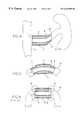
- FIG. 1is a schematic cross-sectional view of a stent in the longitudinal direction according to a first embodiment of the present invention
- FIG. 1Ais a schematic cross-sectional view of a stent in the longitudinal direction according to a second embodiment of the present invention
- FIG. 2is a schematic cross-sectional view of a stent in the longitudinal direction according to a third embodiment of the present invention
- FIG. 2Ais a schematic cross-sectional view of a stent in the longitudinal direction according to a fourth embodiment of the present invention.
- FIG. 3is a schematic cross-sectional view of a stent in the longitudinal direction according to a fifth embodiment of the present invention.
- FIG. 3Ais a schematic cross-sectional view of a stent in the longitudinal direction according to a sixth embodiment of the present invention.
- FIG. 4is a schematic cross-sectional view showing an arrangement of the stent according to the fifth embodiment of the present invention in a branched portion of a hollow vessel;
- FIG. 5is a schematic cross-sectional view showing the arrangement of a stent according to the first embodiment in a hollow vessel.
- FIG. 6is a schematic cross-sectional view of a prior art stent located within a hollow vessel.
- the stent 1in accordance with two embodiments of the present invention is illustrated. Since the second embodiment of FIG. 1A is substantially identical to the first embodiment, similar parts of the stents are designated by the same reference numerals.
- the stent 1consists of a substantially cylindrical stent body, which is made hollow in its interior to enable fluid to pass therethrough.
- the stent body 2consists of a flexible web structure, which is not shown for the sake of clarity. Rather, the stent body 2 will be illustrated as a solid tube for the sake of clarity.
- the flexible web structure of the stent body 2is used for expanding hollow vessels, such as blood vessels or body orifices, and for keeping the vessels or orifices in an expanded state.
- the stent body 2is normally positioned in its non-expanded state within a patient's body inside a narrowed hollow vessel. Then the stent body 2 is expanded by suitable means, for instance by a balloon catheter.
- the stent body 2normally consists of a web structure, which comprises a plurality of neighboring cells, each cell being defined by webs.
- the web structure of the stent body 2can be constructed in a manner that is similar to the web structure disclosed in U.S. patent application Ser. No. 09/171,293, filed on Oct.
- the stent body 2 of the first embodimentis subdivided into three portions, namely a main or center portion 5 , a first end portion 3 and a second end portion 4 .
- the wall thicknesses W E1 and W E2 of the first and second end portions 3 and 4are smaller than the wall thickness W H of the main portion 5 . Also in the first and second embodiments of the present invention, the wall thicknesses W E1 and W E2 of the end portions 3 and 4 are about half the wall thickness W H of the main portion 5 . However, any desired wall thickness ratios W E /W H are possible between end portions and main portion. The wall thicknesses W E1 and W E2 of the two end portions 3 and 4 can also be chosen such that they differ from each other. Moreover, as seen in FIG. 1A, it is possible to vary the flexibility of the stent 1 through different lengths of the end portions 3 and 4 having the reduced wall thickness W E1 or W E2 .
- the main portion 5 and the first and second end portions 3 and 4have arranged therebetween a transition or transitional portion 6 which connects the main portion 5 to the respective end portions 3 and 4 .
- the transition 6 from the main portion 5 to the end portions 3 and 4is stepped or graded. This means that different flexibilities of the respective stent portions are obtained because of the different wall thicknesses of main portion 5 and end portions 3 and 4 , resulting in an improved flexibility because of the smaller wall thickness W E1 or W E2 in the area. Since the transition 6 is configured to be perpendicular to the surface of the end portions 3 and 4 and the main portion 5 , respectively, a sudden change in the flexibility of the stent is obtained in this area.
- a stent of such a designcan very easily be adapted to the respective conditions or natural extension of the vessel 10 .
- the end portions 3 and 4can be adapted to a relatively strong curvature of the hollow vessel 10 .
- the vessel 10extends in a uniform manner without any sudden directional changes, i.e. also in the area of the implanted stent.
- strong irritationswhich are observed in conventional stents, can thus be prevented on the end portions of the stent, whereby the risk of restenosis is considerably reduced.
- FIG. 6shows, by way of comparison, a standard or prior art stent 1 ′, which has been implanted into a hollow vessel 10 .
- the stent body 2 ′ of the stenthas a uniform wall thickness, points or places R which are subjected to strong irritations are observed on the end portions of the stent 1 ′, in particular in the case of the hollow vessel 10 extending in bent fashion.
- Such irritations Rmay be responsible for restenosis, and thus for a narrowing of the hollow vessel 10 , which means that a so-called restenosis is observed in the area of the implanted stent.
- the end portions 3 and 4 of the stent 1which are made flexible according to the invention, such points or places R of considerable irritation can be avoided, since the whole stent 1 can be adapted to the natural bent course of the hollow vessel 10 on account of the increased flexibility in the end portion.
- a sudden change in stiffness which is normally observed between the hollow vessel 10 and the portion of the hollow vessel that is provided with the stentis consequently weakened or attenuated by the flexible ends.
- restenosis caused by irritations on account of the implanted stentcan be reduced in an efficient manner.
- FIGS. 2 and 2Ashow third and fourth embodiments of a stent 1 according to the present invention. Corresponding or identical parts of these stents are designated by the same reference numerals as used in the first embodiment.
- the stent 1has a tubular stent body 2 , which consists of a main portion 5 and two end portions 3 and 4 .
- the wall thickness W E of the end portions 3 and 4is about half the size of the wall thickness W H of the main portion 5 .
- the main portion 5is connected to the end portions 3 and 4 via a respective transition or transitional portion 6 .
- the transition 6is designed such that a continuously extending transition is obtained between main portion 5 and end portions 3 and 4 (cf. FIG. 2 ).
- the wall thickness of the stent body 2increases towards the main portion 5 .
- the flexibility of the stent 1is also changed in this portion. This means that the flexibility of the transitional portion 6 is reduced from the end portion towards the main portion.
- the stent 1 of this embodimentexhibits an increased flexibility in the end portion of the stent 1 , whereby restenosis caused by irritations due to the implanted stent is prevented in an efficient manner.
- the transition 6 between the end portions 3 and 4 and the main portion 5can be designed in response to the desired requirements in such a manner that the flexibility of the transition 6 is changed progressively or stepwise.
- the transition 6may be designed in any desired manner. For instance, a linear or parabolic transition 6 may be provided for, or a transition 6 including a plurality of small steps. In the illustrated embodiments of FIGS. 2 and 2A, transition 6 forms a conical outer surface between the main portion and each of the end portions 3 and 4 .
- FIGS. 3 and 4show a fifth embodiment of a stent according to the present invention, while FIG. 3A shows a sixth embodiment of the present invention.
- Corresponding or identical parts of the stenthave again been designated by the same reference numerals as used in the prior embodiments.
- Each of the stents 1 of these embodimentscomprises a tubular stent body 2 , which has a main portion 5 .
- the stent body 2 of these embodimentshave only arranged thereon one end portion 3 ′ with a smaller wall thickness W E than the main portion 5 .
- the other end of the stent body 2has the same wall thickness W H as the main portion 5 (cf. FIG. 3 ).
- a transition 6 between the main portion 5 and the end portion 3 ′can be stepped as in the first embodiment or gradually sloped as in the third and fourth embodiments.
- the transition 6may be configured in any desired manner that will still carry out the principles of the present invention.
- the stent 1 of the fifth embodimentis primarily used on branches or ramifications of hollow vessels.
- FIG. 4shows, by way of example, a branch or ramus 12 extending from the aorta 11 to the kidney 13 . Since the ramus 12 directly next to the place branching from the aorta 11 extends substantially along the branching direction and is devoid of any torsions or curve-like or curved extensions, or the like, the stent body 2 may be given a standard flexibility in said area. As a consequence, the end of the stent body 2 in the area may have the same wall thickness as the main portion 5 (cf. FIG. 4 ).
- the other end portion 3 ′ of the stent body 2 which is oriented towards the kidney 13is again provided with a smaller wall thickness W E than the main portion 5 , by analogy with the first two embodiments.
- the stent 1can be adapted in an ideal manner to the natural course of the ramus 12 of the hollow vessel, and irritations of the vessel wall can be reduced on the respective end portions of the stent. Since hollow vessels, such as the kidney, are moving on account of inhalation and exhalation processes, the vessel 12 which connects the kidney 13 and the aorta 11 to each other is also moved considerably.
- the flexibility of the vesselis thus increased considerably by the inventive stent of the third embodiment, and irritations of the wall of the vessel are attenuated. As a consequence, the risk of restenosis in the area of the implanted stent is reduced considerably.
Landscapes
- Health & Medical Sciences (AREA)
- Engineering & Computer Science (AREA)
- Biomedical Technology (AREA)
- Cardiology (AREA)
- Oral & Maxillofacial Surgery (AREA)
- Transplantation (AREA)
- Heart & Thoracic Surgery (AREA)
- Vascular Medicine (AREA)
- Life Sciences & Earth Sciences (AREA)
- Animal Behavior & Ethology (AREA)
- General Health & Medical Sciences (AREA)
- Public Health (AREA)
- Veterinary Medicine (AREA)
- Media Introduction/Drainage Providing Device (AREA)
- Prostheses (AREA)
Abstract
Description
Claims (24)
Priority Applications (1)
| Application Number | Priority Date | Filing Date | Title |
|---|---|---|---|
| US09/909,754US6616688B2 (en) | 1998-08-31 | 2001-07-23 | Stent |
Applications Claiming Priority (2)
| Application Number | Priority Date | Filing Date | Title |
|---|---|---|---|
| DE19839646 | 1998-08-31 | ||
| DE19839646ADE19839646A1 (en) | 1998-08-31 | 1998-08-31 | Stent |
Related Child Applications (1)
| Application Number | Title | Priority Date | Filing Date |
|---|---|---|---|
| US09/909,754ContinuationUS6616688B2 (en) | 1998-08-31 | 2001-07-23 | Stent |
Publications (1)
| Publication Number | Publication Date |
|---|---|
| US6264690B1true US6264690B1 (en) | 2001-07-24 |
Family
ID=7879327
Family Applications (2)
| Application Number | Title | Priority Date | Filing Date |
|---|---|---|---|
| US09/379,586Expired - LifetimeUS6264690B1 (en) | 1998-08-31 | 1999-08-24 | Stent having varying thickness along its length |
| US09/909,754Expired - LifetimeUS6616688B2 (en) | 1998-08-31 | 2001-07-23 | Stent |
Family Applications After (1)
| Application Number | Title | Priority Date | Filing Date |
|---|---|---|---|
| US09/909,754Expired - LifetimeUS6616688B2 (en) | 1998-08-31 | 2001-07-23 | Stent |
Country Status (6)
| Country | Link |
|---|---|
| US (2) | US6264690B1 (en) |
| EP (1) | EP0983752B2 (en) |
| JP (1) | JP4695738B2 (en) |
| AT (1) | ATE262855T1 (en) |
| CA (1) | CA2280559C (en) |
| DE (2) | DE19839646A1 (en) |
Cited By (48)
| Publication number | Priority date | Publication date | Assignee | Title |
|---|---|---|---|---|
| US20020019660A1 (en)* | 1998-09-05 | 2002-02-14 | Marc Gianotti | Methods and apparatus for a curved stent |
| US20020052572A1 (en)* | 2000-09-25 | 2002-05-02 | Kenneth Franco | Resorbable anastomosis stents and plugs and their use in patients |
| US20020111620A1 (en)* | 2001-02-14 | 2002-08-15 | Broncus Technologies, Inc. | Devices and methods for maintaining collateral channels in tissue |
| US20030070676A1 (en)* | 1999-08-05 | 2003-04-17 | Cooper Joel D. | Conduits having distal cage structure for maintaining collateral channels in tissue and related methods |
| US20030109917A1 (en)* | 2001-07-18 | 2003-06-12 | Stephen Rudin | Stent vascular intervention device and method |
| US6616688B2 (en)* | 1998-08-31 | 2003-09-09 | Jomed Implantate Gmbh | Stent |
| US6682554B2 (en)* | 1998-09-05 | 2004-01-27 | Jomed Gmbh | Methods and apparatus for a stent having an expandable web structure |
| US6755856B2 (en) | 1998-09-05 | 2004-06-29 | Abbott Laboratories Vascular Enterprises Limited | Methods and apparatus for stenting comprising enhanced embolic protection, coupled with improved protection against restenosis and thrombus formation |
| US20040148005A1 (en)* | 2002-10-17 | 2004-07-29 | Heuser Richard R. | Stent with covering and differential dilation |
| US20050043751A1 (en)* | 2001-09-04 | 2005-02-24 | Broncus Technologies, Inc. | Methods and devices for maintaining patency of surgically created channels in a body organ |
| US20050165428A1 (en)* | 2000-09-25 | 2005-07-28 | Franco Kenneth L. | Absorable surgical structure |
| US20060047222A1 (en)* | 2003-08-27 | 2006-03-02 | Heuser Richard R | Catheter guidewire system using concentric wires |
| US20060256161A1 (en)* | 1997-07-15 | 2006-11-16 | Silverbrook Research Pty Ltd | Ink jet printhead with amorphous ceramic chamber |
| US20060293744A1 (en)* | 2005-06-23 | 2006-12-28 | John Peckham | ePTFE lamination - resizing ePTFE tubing |
| US20070129786A1 (en)* | 2005-10-14 | 2007-06-07 | Bradley Beach | Helical stent |
| US7323189B2 (en) | 2001-10-22 | 2008-01-29 | Ev3 Peripheral, Inc. | Liquid and low melting coatings for stents |
| US7374567B2 (en) | 2006-01-25 | 2008-05-20 | Heuser Richard R | Catheter system for connecting adjacent blood vessels |
| US7462162B2 (en) | 2001-09-04 | 2008-12-09 | Broncus Technologies, Inc. | Antiproliferative devices for maintaining patency of surgically created channels in a body organ |
| US7585318B2 (en) | 2004-06-18 | 2009-09-08 | Boston Scientific Scimed, Inc. | Medical devices and methods of making the same |
| US20100042200A1 (en)* | 2001-03-13 | 2010-02-18 | Medinol, Ltd. | Method and apparatus for stenting |
| US20100094394A1 (en)* | 2008-10-06 | 2010-04-15 | Bradley Beach | Reconstrainable stent delivery system |
| US7803180B2 (en) | 2005-04-04 | 2010-09-28 | Flexible Stenting Solutions, Inc. | Flexible stent |
| US7815763B2 (en) | 2001-09-28 | 2010-10-19 | Abbott Laboratories Vascular Enterprises Limited | Porous membranes for medical implants and methods of manufacture |
| US7850726B2 (en) | 2007-12-20 | 2010-12-14 | Abbott Laboratories Vascular Enterprises Limited | Endoprosthesis having struts linked by foot extensions |
| US7887578B2 (en) | 1998-09-05 | 2011-02-15 | Abbott Laboratories Vascular Enterprises Limited | Stent having an expandable web structure |
| US7914492B2 (en) | 2003-01-27 | 2011-03-29 | Heuser Richard R | Catheter introducer system |
| US20110152905A1 (en)* | 2009-12-22 | 2011-06-23 | Cook Incorporated | Balloon with scoring member |
| US8016874B2 (en) | 2007-05-23 | 2011-09-13 | Abbott Laboratories Vascular Enterprises Limited | Flexible stent with elevated scaffolding properties |
| US8062321B2 (en) | 2006-01-25 | 2011-11-22 | Pq Bypass, Inc. | Catheter system for connecting adjacent blood vessels |
| US8128679B2 (en) | 2007-05-23 | 2012-03-06 | Abbott Laboratories Vascular Enterprises Limited | Flexible stent with torque-absorbing connectors |
| US8337544B2 (en) | 2007-12-20 | 2012-12-25 | Abbott Laboratories Vascular Enterprises Limited | Endoprosthesis having flexible connectors |
| US8409167B2 (en) | 2004-07-19 | 2013-04-02 | Broncus Medical Inc | Devices for delivering substances through an extra-anatomic opening created in an airway |
| US8500794B2 (en) | 2007-08-02 | 2013-08-06 | Flexible Stenting Solutions, Inc. | Flexible stent |
| US8545418B2 (en) | 2004-08-25 | 2013-10-01 | Richard R. Heuser | Systems and methods for ablation of occlusions within blood vessels |
| US8709034B2 (en) | 2011-05-13 | 2014-04-29 | Broncus Medical Inc. | Methods and devices for diagnosing, monitoring, or treating medical conditions through an opening through an airway wall |
| US8864811B2 (en) | 2010-06-08 | 2014-10-21 | Veniti, Inc. | Bi-directional stent delivery system |
| US8920488B2 (en) | 2007-12-20 | 2014-12-30 | Abbott Laboratories Vascular Enterprises Limited | Endoprosthesis having a stable architecture |
| US20150073522A1 (en)* | 2013-09-09 | 2015-03-12 | Boston Scientific Scimed, Inc. | Endoprosthesis devices including biostable and bioabsorable regions |
| US9233014B2 (en) | 2010-09-24 | 2016-01-12 | Veniti, Inc. | Stent with support braces |
| US9301864B2 (en) | 2010-06-08 | 2016-04-05 | Veniti, Inc. | Bi-directional stent delivery system |
| US9345532B2 (en) | 2011-05-13 | 2016-05-24 | Broncus Medical Inc. | Methods and devices for ablation of tissue |
| US9533128B2 (en) | 2003-07-18 | 2017-01-03 | Broncus Medical Inc. | Devices for maintaining patency of surgically created channels in tissue |
| US20170014248A1 (en)* | 2015-07-19 | 2017-01-19 | Sanford Health | Bridging Stent Graft with Combination Balloon Expandable and Self-Expandable Stents and Methods for Use |
| WO2017079691A1 (en)* | 2015-11-05 | 2017-05-11 | Swedish Health Services | Prosthetic phrenoesophageal membrane |
| US9649211B2 (en) | 2009-11-04 | 2017-05-16 | Confluent Medical Technologies, Inc. | Alternating circumferential bridge stent design and methods for use thereof |
| US10092427B2 (en) | 2009-11-04 | 2018-10-09 | Confluent Medical Technologies, Inc. | Alternating circumferential bridge stent design and methods for use thereof |
| US10272260B2 (en) | 2011-11-23 | 2019-04-30 | Broncus Medical Inc. | Methods and devices for diagnosing, monitoring, or treating medical conditions through an opening through an airway wall |
| WO2025074253A1 (en) | 2023-10-02 | 2025-04-10 | Otsuka Medical Devices Co., Ltd. | Stents |
Families Citing this family (27)
| Publication number | Priority date | Publication date | Assignee | Title |
|---|---|---|---|---|
| CA2079417C (en) | 1991-10-28 | 2003-01-07 | Lilip Lau | Expandable stents and method of making same |
| US7204848B1 (en) | 1995-03-01 | 2007-04-17 | Boston Scientific Scimed, Inc. | Longitudinally flexible expandable stent |
| US6273911B1 (en) | 1999-04-22 | 2001-08-14 | Advanced Cardiovascular Systems, Inc. | Variable strength stent |
| DE10118944B4 (en) | 2001-04-18 | 2013-01-31 | Merit Medical Systems, Inc. | Removable, essentially cylindrical implants |
| AU2002320456A1 (en) | 2001-07-26 | 2003-02-17 | Alveolus Inc. | Removable stent and method of using the same |
| US7959671B2 (en) | 2002-11-05 | 2011-06-14 | Merit Medical Systems, Inc. | Differential covering and coating methods |
| US7875068B2 (en)* | 2002-11-05 | 2011-01-25 | Merit Medical Systems, Inc. | Removable biliary stent |
| US7637942B2 (en) | 2002-11-05 | 2009-12-29 | Merit Medical Systems, Inc. | Coated stent with geometry determinated functionality and method of making the same |
| US7527644B2 (en) | 2002-11-05 | 2009-05-05 | Alveolus Inc. | Stent with geometry determinated functionality and method of making the same |
| JP4566988B2 (en)* | 2003-04-02 | 2010-10-20 | ボストン サイエンティフィック リミテッド | Separable and recoverable stent assembly |
| US7112216B2 (en)* | 2003-05-28 | 2006-09-26 | Boston Scientific Scimed, Inc. | Stent with tapered flexibility |
| US7338530B2 (en)* | 2003-11-24 | 2008-03-04 | Checkmed Systems, Inc. | Stent |
| US7887579B2 (en) | 2004-09-29 | 2011-02-15 | Merit Medical Systems, Inc. | Active stent |
| US7767848B2 (en) | 2005-02-08 | 2010-08-03 | Celanese International Corporation | Method of controlling acetic acid process |
| US8628565B2 (en)* | 2005-04-13 | 2014-01-14 | Abbott Cardiovascular Systems Inc. | Intravascular stent |
| US7731654B2 (en) | 2005-05-13 | 2010-06-08 | Merit Medical Systems, Inc. | Delivery device with viewing window and associated method |
| US7339370B2 (en)* | 2005-12-09 | 2008-03-04 | Bourns, Inc. | Position and torque sensor |
| CN101472627B (en)* | 2006-01-30 | 2013-05-08 | 国立成功大学 | Dual-pulsation bi-ventricular assist device |
| US7988720B2 (en) | 2006-09-12 | 2011-08-02 | Boston Scientific Scimed, Inc. | Longitudinally flexible expandable stent |
| EP2349080B1 (en)* | 2008-10-22 | 2016-04-13 | Boston Scientific Scimed, Inc. | Shape memory tubular stent with grooves |
| US8448528B2 (en) | 2010-09-27 | 2013-05-28 | Bourns Incorporated | Three-piece torque sensor assembly |
| US8390276B2 (en) | 2010-09-27 | 2013-03-05 | Bourns Incorporated | Target magnet assembly for a sensor used with a steering gear |
| CN103442668B (en)* | 2011-03-22 | 2016-05-18 | 泰尔茂株式会社 | Support |
| WO2013052528A1 (en) | 2011-10-04 | 2013-04-11 | Cook Medical Technologies Llc | Reduced wire profile stent |
| EP2810622B1 (en)* | 2012-01-30 | 2019-04-24 | Kawasumi Laboratories, Inc. | Biliary stent |
| US9610179B2 (en) | 2013-03-12 | 2017-04-04 | Cook Medical Technologies Llc | Atraumatic stent crowns |
| US10117763B2 (en) | 2014-03-18 | 2018-11-06 | Boston Scientific Scimed, Inc. | Reduced granulation and inflammation stent design |
Citations (9)
| Publication number | Priority date | Publication date | Assignee | Title |
|---|---|---|---|---|
| US5141516A (en)* | 1989-07-26 | 1992-08-25 | Detweiler Mark B | Dissolvable anastomosis stent and method for using the same |
| US5476506A (en)* | 1994-02-08 | 1995-12-19 | Ethicon, Inc. | Bi-directional crimped graft |
| US5609605A (en)* | 1994-08-25 | 1997-03-11 | Ethicon, Inc. | Combination arterial stent |
| US5807327A (en)* | 1995-12-08 | 1998-09-15 | Ethicon, Inc. | Catheter assembly |
| US5836966A (en)* | 1997-05-22 | 1998-11-17 | Scimed Life Systems, Inc. | Variable expansion force stent |
| US5906641A (en)* | 1997-05-27 | 1999-05-25 | Schneider (Usa) Inc | Bifurcated stent graft |
| US6010529A (en)* | 1996-12-03 | 2000-01-04 | Atrium Medical Corporation | Expandable shielded vessel support |
| US6027517A (en)* | 1994-02-24 | 2000-02-22 | Radiance Medical Systems, Inc. | Fixed focal balloon for interactive angioplasty and stent implantation catheter with focalized balloon |
| US6076529A (en)* | 1998-04-20 | 2000-06-20 | Heartstent Corporation | Transmyocardial implant with inserted vessel |
Family Cites Families (12)
| Publication number | Priority date | Publication date | Assignee | Title |
|---|---|---|---|---|
| DE3811231A1 (en)† | 1988-04-02 | 1989-10-12 | Beiersdorf Ag | Surgical implants |
| US4856516A (en)† | 1989-01-09 | 1989-08-15 | Cordis Corporation | Endovascular stent apparatus and method |
| JPH02277467A (en)† | 1989-04-19 | 1990-11-14 | Olympus Optical Co Ltd | Living body internal stay tube |
| DE19537872C2 (en)† | 1995-10-11 | 2003-06-18 | Eckhard Alt | Expandable stent and method of making it |
| US5643279A (en)* | 1996-03-12 | 1997-07-01 | Cordis Corporation | Method of catheter balloon manufacture and use |
| NZ331269A (en)* | 1996-04-10 | 2000-01-28 | Advanced Cardiovascular System | Expandable stent, its structural strength varying along its length |
| US5807404A (en)† | 1996-09-19 | 1998-09-15 | Medinol Ltd. | Stent with variable features to optimize support and method of making such stent |
| DE29702671U1 (en)* | 1997-02-17 | 1997-04-10 | Jomed Implantate GmbH, 72414 Rangendingen | Stent |
| DE19720115C2 (en)† | 1997-05-14 | 1999-05-20 | Jomed Implantate Gmbh | Stent graft |
| DE29708879U1 (en)† | 1997-05-20 | 1997-07-31 | Jomed Implantate GmbH, 72414 Rangendingen | Coronary stent |
| DE19839646A1 (en)* | 1998-08-31 | 2000-03-09 | Jomed Implantate Gmbh | Stent |
| US6325825B1 (en)* | 1999-04-08 | 2001-12-04 | Cordis Corporation | Stent with variable wall thickness |
- 1998
- 1998-08-31DEDE19839646Apatent/DE19839646A1/ennot_activeCeased
- 1999
- 1999-06-29ATAT99112417Tpatent/ATE262855T1/ennot_activeIP Right Cessation
- 1999-06-29DEDE59909005Tpatent/DE59909005D1/ennot_activeExpired - Lifetime
- 1999-06-29EPEP99112417Apatent/EP0983752B2/ennot_activeExpired - Lifetime
- 1999-08-23CACA002280559Apatent/CA2280559C/ennot_activeExpired - Fee Related
- 1999-08-24USUS09/379,586patent/US6264690B1/ennot_activeExpired - Lifetime
- 1999-08-27JPJP24079799Apatent/JP4695738B2/ennot_activeExpired - Fee Related
- 2001
- 2001-07-23USUS09/909,754patent/US6616688B2/ennot_activeExpired - Lifetime
Patent Citations (9)
| Publication number | Priority date | Publication date | Assignee | Title |
|---|---|---|---|---|
| US5141516A (en)* | 1989-07-26 | 1992-08-25 | Detweiler Mark B | Dissolvable anastomosis stent and method for using the same |
| US5476506A (en)* | 1994-02-08 | 1995-12-19 | Ethicon, Inc. | Bi-directional crimped graft |
| US6027517A (en)* | 1994-02-24 | 2000-02-22 | Radiance Medical Systems, Inc. | Fixed focal balloon for interactive angioplasty and stent implantation catheter with focalized balloon |
| US5609605A (en)* | 1994-08-25 | 1997-03-11 | Ethicon, Inc. | Combination arterial stent |
| US5807327A (en)* | 1995-12-08 | 1998-09-15 | Ethicon, Inc. | Catheter assembly |
| US6010529A (en)* | 1996-12-03 | 2000-01-04 | Atrium Medical Corporation | Expandable shielded vessel support |
| US5836966A (en)* | 1997-05-22 | 1998-11-17 | Scimed Life Systems, Inc. | Variable expansion force stent |
| US5906641A (en)* | 1997-05-27 | 1999-05-25 | Schneider (Usa) Inc | Bifurcated stent graft |
| US6076529A (en)* | 1998-04-20 | 2000-06-20 | Heartstent Corporation | Transmyocardial implant with inserted vessel |
Cited By (105)
| Publication number | Priority date | Publication date | Assignee | Title |
|---|---|---|---|---|
| US20060256161A1 (en)* | 1997-07-15 | 2006-11-16 | Silverbrook Research Pty Ltd | Ink jet printhead with amorphous ceramic chamber |
| US6616688B2 (en)* | 1998-08-31 | 2003-09-09 | Jomed Implantate Gmbh | Stent |
| US20020019660A1 (en)* | 1998-09-05 | 2002-02-14 | Marc Gianotti | Methods and apparatus for a curved stent |
| US7842079B2 (en) | 1998-09-05 | 2010-11-30 | Abbott Laboratories Vascular Enterprises Limited | Apparatus for a stent having an expandable web structure and delivery system |
| US9517146B2 (en) | 1998-09-05 | 2016-12-13 | Abbott Laboratories Vascular Enterprises Limited | Methods and apparatus for stenting comprising enhanced embolic protection coupled with improved protections against restenosis and thrombus formation |
| US8814926B2 (en) | 1998-09-05 | 2014-08-26 | Abbott Laboratories Vascular Enterprises Limited | Methods and apparatus for stenting comprising enhanced embolic protection coupled with improved protections against restenosis and thrombus formation |
| US8088157B2 (en) | 1998-09-05 | 2012-01-03 | Abbott Laboratories Vascular Enterprises Limited | Methods and apparatus for stenting comprising enhanced embolic protection coupled with improved protections against restenosis and thrombus formation |
| US6755856B2 (en) | 1998-09-05 | 2004-06-29 | Abbott Laboratories Vascular Enterprises Limited | Methods and apparatus for stenting comprising enhanced embolic protection, coupled with improved protection against restenosis and thrombus formation |
| US8343208B2 (en) | 1998-09-05 | 2013-01-01 | Abbott Laboratories Vascular Enterprises Limited | Stent having an expandable web structure |
| US20050004651A1 (en)* | 1998-09-05 | 2005-01-06 | Abbott Laboratories Vascular Enterprises Limited | Methods and apparatus for a stent having an expandable web structure and delivery system |
| US20050004659A1 (en)* | 1998-09-05 | 2005-01-06 | Abbott Laboratories Vascular Enterprises Limited | Methods and apparatus for stent having an expandable web structure |
| US7789905B2 (en) | 1998-09-05 | 2010-09-07 | Abbottt Laboratories Vascular Enterprises Limited | Apparatus for a stent having an expandable web structure |
| US8303645B2 (en) | 1998-09-05 | 2012-11-06 | Abbott Laboratories Vascular Enterprises Limited | Methods and apparatus for a stent having an expandable web structure |
| US7794491B2 (en) | 1998-09-05 | 2010-09-14 | Abbott Laboratories Vascular Enterprises Limited | Apparatus for a stent having an expandable web structure and delivery system |
| US7811314B2 (en) | 1998-09-05 | 2010-10-12 | Abbott Laboratories Vascular Enterprises Limited | Methods and apparatus for stenting comprising enhanced embolic protection coupled with improved protections against restenosis and thrombus formation |
| US7789904B2 (en) | 1998-09-05 | 2010-09-07 | Abbott Laboratories Vascular Enterprises Limited | Methods and apparatus for a stent having an expandable web structure |
| US6682554B2 (en)* | 1998-09-05 | 2004-01-27 | Jomed Gmbh | Methods and apparatus for a stent having an expandable web structure |
| US7927364B2 (en) | 1998-09-05 | 2011-04-19 | Abbott Laboratories Vascular Enterprises Limited | Methods and apparatus for stenting comprising enhanced embolic protection coupled with improved protections against restenosis and thrombus formation |
| US7927365B2 (en) | 1998-09-05 | 2011-04-19 | Abbott Laboratories Vascular Enterprises Limited | Methods and apparatus for stenting comprising enhanced embolic protection coupled with improved protections against restenosis and thrombus formation |
| US20070179593A1 (en)* | 1998-09-05 | 2007-08-02 | Abbott Laboratories Vascular | Methods and apparatus for stenting comprising enhanced embolic protection coupled with improved protecions against restenosis and thrombus formation |
| US7887578B2 (en) | 1998-09-05 | 2011-02-15 | Abbott Laboratories Vascular Enterprises Limited | Stent having an expandable web structure |
| US7887577B2 (en) | 1998-09-05 | 2011-02-15 | Abbott Laboratories Vascular Enterprises Limited | Apparatus for a stent having an expandable web structure |
| US10420637B2 (en) | 1998-09-05 | 2019-09-24 | Abbott Laboratories Vascular Enterprises Limited | Methods and apparatus for stenting comprising enhanced embolic protection coupled with improved protections against restenosis and thrombus formation |
| US7846196B2 (en) | 1998-09-05 | 2010-12-07 | Abbott Laboratories Vascular Enterprises Limited | Apparatus for a stent having an expandable web structure |
| US7842078B2 (en) | 1998-09-05 | 2010-11-30 | Abbott Laboratories Vascular Enterprises Limited | Apparatus for a stent having an expandable web structure and delivery system |
| US7815672B2 (en) | 1998-09-05 | 2010-10-19 | Abbott Laboratories Vascular Enterprises Limited | Apparatus for a stent having an expandable web structure |
| US20030070676A1 (en)* | 1999-08-05 | 2003-04-17 | Cooper Joel D. | Conduits having distal cage structure for maintaining collateral channels in tissue and related methods |
| US20020052572A1 (en)* | 2000-09-25 | 2002-05-02 | Kenneth Franco | Resorbable anastomosis stents and plugs and their use in patients |
| US20050165428A1 (en)* | 2000-09-25 | 2005-07-28 | Franco Kenneth L. | Absorable surgical structure |
| US20050004584A1 (en)* | 2000-09-25 | 2005-01-06 | Cohesion Technologies, Inc. | Resorbable anastomosis stents and plugs and their use in patients |
| US7175644B2 (en)* | 2001-02-14 | 2007-02-13 | Broncus Technologies, Inc. | Devices and methods for maintaining collateral channels in tissue |
| US20020111620A1 (en)* | 2001-02-14 | 2002-08-15 | Broncus Technologies, Inc. | Devices and methods for maintaining collateral channels in tissue |
| US9492293B2 (en) | 2001-03-13 | 2016-11-15 | Medinol Ltd. | Method and apparatus for stenting |
| US20100042200A1 (en)* | 2001-03-13 | 2010-02-18 | Medinol, Ltd. | Method and apparatus for stenting |
| US20030109917A1 (en)* | 2001-07-18 | 2003-06-12 | Stephen Rudin | Stent vascular intervention device and method |
| US20050043751A1 (en)* | 2001-09-04 | 2005-02-24 | Broncus Technologies, Inc. | Methods and devices for maintaining patency of surgically created channels in a body organ |
| US7708712B2 (en) | 2001-09-04 | 2010-05-04 | Broncus Technologies, Inc. | Methods and devices for maintaining patency of surgically created channels in a body organ |
| US7462162B2 (en) | 2001-09-04 | 2008-12-09 | Broncus Technologies, Inc. | Antiproliferative devices for maintaining patency of surgically created channels in a body organ |
| US7815763B2 (en) | 2001-09-28 | 2010-10-19 | Abbott Laboratories Vascular Enterprises Limited | Porous membranes for medical implants and methods of manufacture |
| US8449905B2 (en) | 2001-10-22 | 2013-05-28 | Covidien Lp | Liquid and low melting coatings for stents |
| US7323189B2 (en) | 2001-10-22 | 2008-01-29 | Ev3 Peripheral, Inc. | Liquid and low melting coatings for stents |
| US8900618B2 (en) | 2001-10-22 | 2014-12-02 | Covidien Lp | Liquid and low melting coatings for stents |
| US7622135B2 (en) | 2001-10-22 | 2009-11-24 | Ev3 Peripheral, Inc. | Coated stent |
| US9333279B2 (en) | 2001-10-22 | 2016-05-10 | Covidien Lp | Coated stent comprising an HMG-CoA reductase inhibitor |
| US7300459B2 (en) | 2002-10-17 | 2007-11-27 | Heuser Richard R | Stent with covering and differential dilation |
| US20040148005A1 (en)* | 2002-10-17 | 2004-07-29 | Heuser Richard R. | Stent with covering and differential dilation |
| US7914492B2 (en) | 2003-01-27 | 2011-03-29 | Heuser Richard R | Catheter introducer system |
| US9533128B2 (en) | 2003-07-18 | 2017-01-03 | Broncus Medical Inc. | Devices for maintaining patency of surgically created channels in tissue |
| US7402141B2 (en) | 2003-08-27 | 2008-07-22 | Heuser Richard R | Catheter guidewire system using concentric wires |
| US20060047222A1 (en)* | 2003-08-27 | 2006-03-02 | Heuser Richard R | Catheter guidewire system using concentric wires |
| US7585318B2 (en) | 2004-06-18 | 2009-09-08 | Boston Scientific Scimed, Inc. | Medical devices and methods of making the same |
| US8409167B2 (en) | 2004-07-19 | 2013-04-02 | Broncus Medical Inc | Devices for delivering substances through an extra-anatomic opening created in an airway |
| US11357960B2 (en) | 2004-07-19 | 2022-06-14 | Broncus Medical Inc. | Devices for delivering substances through an extra-anatomic opening created in an airway |
| US8784400B2 (en) | 2004-07-19 | 2014-07-22 | Broncus Medical Inc. | Devices for delivering substances through an extra-anatomic opening created in an airway |
| US10369339B2 (en) | 2004-07-19 | 2019-08-06 | Broncus Medical Inc. | Devices for delivering substances through an extra-anatomic opening created in an airway |
| US8608724B2 (en) | 2004-07-19 | 2013-12-17 | Broncus Medical Inc. | Devices for delivering substances through an extra-anatomic opening created in an airway |
| US8545418B2 (en) | 2004-08-25 | 2013-10-01 | Richard R. Heuser | Systems and methods for ablation of occlusions within blood vessels |
| US9592137B2 (en) | 2005-04-04 | 2017-03-14 | Flexible Stenting Solutions, Inc. | Flexible stent |
| US7803180B2 (en) | 2005-04-04 | 2010-09-28 | Flexible Stenting Solutions, Inc. | Flexible stent |
| US7963988B2 (en) | 2005-06-23 | 2011-06-21 | Boston Scientific Scimed, Inc. | ePTFE lamination—resizing ePTFE tubing |
| US20060293744A1 (en)* | 2005-06-23 | 2006-12-28 | John Peckham | ePTFE lamination - resizing ePTFE tubing |
| US20070129786A1 (en)* | 2005-10-14 | 2007-06-07 | Bradley Beach | Helical stent |
| US8956400B2 (en)* | 2005-10-14 | 2015-02-17 | Flexible Stenting Solutions, Inc. | Helical stent |
| US7374567B2 (en) | 2006-01-25 | 2008-05-20 | Heuser Richard R | Catheter system for connecting adjacent blood vessels |
| US8062321B2 (en) | 2006-01-25 | 2011-11-22 | Pq Bypass, Inc. | Catheter system for connecting adjacent blood vessels |
| WO2008016626A3 (en)* | 2006-08-01 | 2008-12-04 | Flexible Stenting Solutions Ll | Helical stent |
| US9913969B2 (en) | 2006-10-05 | 2018-03-13 | Broncus Medical Inc. | Devices for delivering substances through an extra-anatomic opening created in an airway |
| US8128679B2 (en) | 2007-05-23 | 2012-03-06 | Abbott Laboratories Vascular Enterprises Limited | Flexible stent with torque-absorbing connectors |
| US9320627B2 (en) | 2007-05-23 | 2016-04-26 | Abbott Laboratories Vascular Enterprises Limited | Flexible stent with torque-absorbing connectors |
| US8016874B2 (en) | 2007-05-23 | 2011-09-13 | Abbott Laboratories Vascular Enterprises Limited | Flexible stent with elevated scaffolding properties |
| US8500794B2 (en) | 2007-08-02 | 2013-08-06 | Flexible Stenting Solutions, Inc. | Flexible stent |
| US8246674B2 (en) | 2007-12-20 | 2012-08-21 | Abbott Laboratories Vascular Enterprises Limited | Endoprosthesis having struts linked by foot extensions |
| US8337544B2 (en) | 2007-12-20 | 2012-12-25 | Abbott Laboratories Vascular Enterprises Limited | Endoprosthesis having flexible connectors |
| US7850726B2 (en) | 2007-12-20 | 2010-12-14 | Abbott Laboratories Vascular Enterprises Limited | Endoprosthesis having struts linked by foot extensions |
| US8920488B2 (en) | 2007-12-20 | 2014-12-30 | Abbott Laboratories Vascular Enterprises Limited | Endoprosthesis having a stable architecture |
| US20100094394A1 (en)* | 2008-10-06 | 2010-04-15 | Bradley Beach | Reconstrainable stent delivery system |
| US10010438B2 (en) | 2008-10-06 | 2018-07-03 | Flexible Stenting Solutions, Inc. | Reconstrainable stent delivery system |
| US9149376B2 (en) | 2008-10-06 | 2015-10-06 | Cordis Corporation | Reconstrainable stent delivery system |
| US10744012B2 (en) | 2009-11-04 | 2020-08-18 | Boston Scientific Scimed, Inc. | Alternating circumferential bridge stent design and methods for use thereof |
| US10092427B2 (en) | 2009-11-04 | 2018-10-09 | Confluent Medical Technologies, Inc. | Alternating circumferential bridge stent design and methods for use thereof |
| US9649211B2 (en) | 2009-11-04 | 2017-05-16 | Confluent Medical Technologies, Inc. | Alternating circumferential bridge stent design and methods for use thereof |
| US20110152905A1 (en)* | 2009-12-22 | 2011-06-23 | Cook Incorporated | Balloon with scoring member |
| US8348987B2 (en)* | 2009-12-22 | 2013-01-08 | Cook Medical Technologies Llc | Balloon with scoring member |
| US9314360B2 (en) | 2010-06-08 | 2016-04-19 | Veniti, Inc. | Bi-directional stent delivery system |
| US9301864B2 (en) | 2010-06-08 | 2016-04-05 | Veniti, Inc. | Bi-directional stent delivery system |
| US8864811B2 (en) | 2010-06-08 | 2014-10-21 | Veniti, Inc. | Bi-directional stent delivery system |
| US9233014B2 (en) | 2010-09-24 | 2016-01-12 | Veniti, Inc. | Stent with support braces |
| US10959866B2 (en) | 2010-09-24 | 2021-03-30 | Boston Scientific Scimed, Inc. | Stent with support braces |
| US9345532B2 (en) | 2011-05-13 | 2016-05-24 | Broncus Medical Inc. | Methods and devices for ablation of tissue |
| US8932316B2 (en) | 2011-05-13 | 2015-01-13 | Broncus Medical Inc. | Methods and devices for diagnosing, monitoring, or treating medical conditions through an opening through an airway wall |
| US9993306B2 (en) | 2011-05-13 | 2018-06-12 | Broncus Medical Inc. | Methods and devices for diagnosing, monitoring, or treating medical conditions through an opening through an airway wall |
| US12016640B2 (en) | 2011-05-13 | 2024-06-25 | Broncus Medical Inc. | Methods and devices for diagnosing, monitoring, or treating medical conditions through an opening through an airway wall |
| US9486229B2 (en) | 2011-05-13 | 2016-11-08 | Broncus Medical Inc. | Methods and devices for excision of tissue |
| US9421070B2 (en) | 2011-05-13 | 2016-08-23 | Broncus Medical Inc. | Methods and devices for diagnosing, monitoring, or treating medical conditions through an opening through an airway wall |
| US10631938B2 (en) | 2011-05-13 | 2020-04-28 | Broncus Medical Inc. | Methods and devices for diagnosing, monitoring, or treating medical conditions through an opening through an airway wall |
| US8709034B2 (en) | 2011-05-13 | 2014-04-29 | Broncus Medical Inc. | Methods and devices for diagnosing, monitoring, or treating medical conditions through an opening through an airway wall |
| US10272260B2 (en) | 2011-11-23 | 2019-04-30 | Broncus Medical Inc. | Methods and devices for diagnosing, monitoring, or treating medical conditions through an opening through an airway wall |
| US9320628B2 (en)* | 2013-09-09 | 2016-04-26 | Boston Scientific Scimed, Inc. | Endoprosthesis devices including biostable and bioabsorable regions |
| US20150073522A1 (en)* | 2013-09-09 | 2015-03-12 | Boston Scientific Scimed, Inc. | Endoprosthesis devices including biostable and bioabsorable regions |
| US10327924B2 (en)* | 2015-07-19 | 2019-06-25 | Sanford Health | Bridging stent graft with combination balloon expandable and self-expandable stents and methods for use |
| US20170014248A1 (en)* | 2015-07-19 | 2017-01-19 | Sanford Health | Bridging Stent Graft with Combination Balloon Expandable and Self-Expandable Stents and Methods for Use |
| WO2017079691A1 (en)* | 2015-11-05 | 2017-05-11 | Swedish Health Services | Prosthetic phrenoesophageal membrane |
| US20180353278A1 (en)* | 2015-11-05 | 2018-12-13 | Swedish Health Services | Prosthetic phrenoesophageal membrane |
| WO2025074253A1 (en) | 2023-10-02 | 2025-04-10 | Otsuka Medical Devices Co., Ltd. | Stents |
| GB2634709A (en)* | 2023-10-02 | 2025-04-23 | Otsuka Medical Devices Co Ltd | Stents |
Also Published As
| Publication number | Publication date |
|---|---|
| ATE262855T1 (en) | 2004-04-15 |
| DE59909005D1 (en) | 2004-05-06 |
| CA2280559A1 (en) | 2000-02-29 |
| US20010041929A1 (en) | 2001-11-15 |
| EP0983752B2 (en) | 2010-06-09 |
| US6616688B2 (en) | 2003-09-09 |
| EP0983752A2 (en) | 2000-03-08 |
| JP2000070379A (en) | 2000-03-07 |
| JP4695738B2 (en) | 2011-06-08 |
| EP0983752B1 (en) | 2004-03-31 |
| EP0983752A3 (en) | 2000-04-05 |
| CA2280559C (en) | 2006-11-28 |
| DE19839646A1 (en) | 2000-03-09 |
Similar Documents
| Publication | Publication Date | Title |
|---|---|---|
| US6264690B1 (en) | Stent having varying thickness along its length | |
| US9872758B2 (en) | Stent | |
| US6264688B1 (en) | Radially expandable stent V | |
| US6048361A (en) | Balloon catheter and multi-guidewire stent for implanting in the region of branched vessels | |
| JP4996633B2 (en) | Stent with changing expansion force | |
| US6416539B1 (en) | Controlled length intraluminal implant | |
| US6610086B1 (en) | Radially expandable stent IV | |
| US6852123B2 (en) | Micro structure stent configurations | |
| US6916336B2 (en) | Vascular prosthesis | |
| US5931867A (en) | Radially expandable support device | |
| EP0846449B1 (en) | A flexible expandable stent | |
| US5620457A (en) | Catheter balloon | |
| US6461381B2 (en) | Flexible expandable stent | |
| US6719782B1 (en) | Flat wire stent | |
| US8328864B2 (en) | Stent having phased hoop sections | |
| US6264685B1 (en) | Flexible high radial strength stent | |
| CN1178664A (en) | Stent with varible features to optimize support and method of making such stent | |
| KR20000070147A (en) | luminal endoprosthesis for ramification | |
| CZ289423B6 (en) | Expandable intravascular stent | |
| US6796998B2 (en) | Stent |
Legal Events
| Date | Code | Title | Description |
|---|---|---|---|
| AS | Assignment | Owner name:JOMED IMPLANTATE GMBH, GERMANY Free format text:ASSIGNMENT OF ASSIGNORS INTEREST;ASSIGNOR:VON OEPEN, RANDOLPH;REEL/FRAME:010412/0469 Effective date:19990820 | |
| STCF | Information on status: patent grant | Free format text:PATENTED CASE | |
| AS | Assignment | Owner name:ABBOTT LABORATORIES VASCULAR ENTITIES LIMITED, IRE Free format text:ASSIGNMENT OF ASSIGNORS INTEREST;ASSIGNOR:JOMED GMBH;REEL/FRAME:014033/0838 Effective date:20030630 | |
| FPAY | Fee payment | Year of fee payment:4 | |
| FEPP | Fee payment procedure | Free format text:PAT HOLDER NO LONGER CLAIMS SMALL ENTITY STATUS, ENTITY STATUS SET TO UNDISCOUNTED (ORIGINAL EVENT CODE: STOL); ENTITY STATUS OF PATENT OWNER: LARGE ENTITY | |
| REFU | Refund | Free format text:REFUND - SURCHARGE, PETITION TO ACCEPT PYMT AFTER EXP, UNINTENTIONAL (ORIGINAL EVENT CODE: R2551); ENTITY STATUS OF PATENT OWNER: LARGE ENTITY | |
| AS | Assignment | Owner name:ABBOTT LABORATORIES VASCULAR ENTERPRISES LIMITED, Free format text:CORRECTIVE ASSIGNMENT TO CORRECT THE NAME OF ASSIGNEE ON ASSIGNMENT DOCUMENT (SECOND PARAGRAPH) PREVIOUSLY RECORDED ON REEL 014033 FRAME 0838;ASSIGNOR:JOMED GMBH;REEL/FRAME:019936/0603 Effective date:20030630 | |
| FPAY | Fee payment | Year of fee payment:8 | |
| FPAY | Fee payment | Year of fee payment:12 | |
| AS | Assignment | Owner name:JOMED GMBH, GERMANY Free format text:CHANGE OF NAME;ASSIGNOR:JOMED IMPLANTATE GMBH;REEL/FRAME:049154/0064 Effective date:19990616 |