US6264679B1 - Heat exchange catheter with discrete heat exchange elements - Google Patents
Heat exchange catheter with discrete heat exchange elementsDownload PDFInfo
- Publication number
- US6264679B1 US6264679B1US09/378,578US37857899AUS6264679B1US 6264679 B1US6264679 B1US 6264679B1US 37857899 AUS37857899 AUS 37857899AUS 6264679 B1US6264679 B1US 6264679B1
- Authority
- US
- United States
- Prior art keywords
- heat exchange
- catheter
- shaft
- fluid
- region
- Prior art date
- Legal status (The legal status is an assumption and is not a legal conclusion. Google has not performed a legal analysis and makes no representation as to the accuracy of the status listed.)
- Expired - Lifetime
Links
- 239000012530fluidSubstances0.000claimsabstractdescription116
- 210000001124body fluidAnatomy0.000claimsabstractdescription46
- 239000010839body fluidSubstances0.000claimsabstractdescription46
- 230000004087circulationEffects0.000claimsabstractdescription36
- 238000004891communicationMethods0.000claimsabstractdescription20
- 238000012546transferMethods0.000claimsdescription28
- 230000037361pathwayEffects0.000claimsdescription10
- 239000007788liquidSubstances0.000claimsdescription4
- 230000000717retained effectEffects0.000claimsdescription2
- 239000008280bloodSubstances0.000description59
- 210000004369bloodAnatomy0.000description59
- 230000002631hypothermal effectEffects0.000description40
- 206010021113HypothermiaDiseases0.000description39
- 238000001816coolingMethods0.000description39
- 238000000034methodMethods0.000description29
- 230000037000normothermiaEffects0.000description15
- 210000004556brainAnatomy0.000description14
- 238000010438heat treatmentMethods0.000description12
- 230000001331thermoregulatory effectEffects0.000description12
- 210000005239tubuleAnatomy0.000description12
- 238000001356surgical procedureMethods0.000description11
- 230000017531blood circulationEffects0.000description10
- 239000013529heat transfer fluidSubstances0.000description10
- 230000007246mechanismEffects0.000description10
- 210000001519tissueAnatomy0.000description10
- 238000003780insertionMethods0.000description9
- 230000037431insertionEffects0.000description9
- 230000036760body temperatureEffects0.000description8
- 238000010276constructionMethods0.000description8
- 230000000694effectsEffects0.000description8
- 230000006870functionEffects0.000description8
- 210000002216heartAnatomy0.000description8
- 230000001965increasing effectEffects0.000description8
- 206010008531ChillsDiseases0.000description7
- 210000004204blood vesselAnatomy0.000description7
- 230000006378damageEffects0.000description7
- 230000004044responseEffects0.000description7
- 206010037660PyrexiaDiseases0.000description6
- 208000014674injuryDiseases0.000description6
- 238000010792warmingMethods0.000description6
- 208000006011StrokeDiseases0.000description5
- 206010047139VasoconstrictionDiseases0.000description5
- 238000004382pottingMethods0.000description5
- 238000005086pumpingMethods0.000description5
- 239000000523sampleSubstances0.000description5
- 230000025033vasoconstrictionEffects0.000description5
- 210000000746body regionAnatomy0.000description4
- 230000001276controlling effectEffects0.000description4
- 239000007789gasSubstances0.000description4
- 208000020658intracerebral hemorrhageDiseases0.000description4
- 230000001105regulatory effectEffects0.000description4
- XLYOFNOQVPJJNP-UHFFFAOYSA-NwaterSubstancesOXLYOFNOQVPJJNP-UHFFFAOYSA-N0.000description4
- 206010002091AnaesthesiaDiseases0.000description3
- 208000027418Wounds and injuryDiseases0.000description3
- 230000002411adverseEffects0.000description3
- 230000037005anaesthesiaEffects0.000description3
- 230000008901benefitEffects0.000description3
- 210000001715carotid arteryAnatomy0.000description3
- 150000001875compoundsChemical class0.000description3
- 201000010099diseaseDiseases0.000description3
- 208000037265diseases, disorders, signs and symptomsDiseases0.000description3
- 210000003717douglas' pouchAnatomy0.000description3
- 238000007667floatingMethods0.000description3
- 230000001939inductive effectEffects0.000description3
- 239000000463materialSubstances0.000description3
- 230000002503metabolic effectEffects0.000description3
- 208000010125myocardial infarctionDiseases0.000description3
- 210000004165myocardiumAnatomy0.000description3
- 230000004112neuroprotectionEffects0.000description3
- 230000029058respiratory gaseous exchangeEffects0.000description3
- 238000000926separation methodMethods0.000description3
- 230000008733traumaEffects0.000description3
- 210000005166vasculatureAnatomy0.000description3
- 206010002329AneurysmDiseases0.000description2
- CURLTUGMZLYLDI-UHFFFAOYSA-NCarbon dioxideChemical compoundO=C=OCURLTUGMZLYLDI-UHFFFAOYSA-N0.000description2
- 206010008111Cerebral haemorrhageDiseases0.000description2
- 206010019196Head injuryDiseases0.000description2
- 208000010496Heart ArrestDiseases0.000description2
- 208000016988Hemorrhagic StrokeDiseases0.000description2
- 208000032382Ischaemic strokeDiseases0.000description2
- 208000012902Nervous system diseaseDiseases0.000description2
- 208000025966Neurological diseaseDiseases0.000description2
- 239000000853adhesiveSubstances0.000description2
- 230000001070adhesive effectEffects0.000description2
- 210000000709aortaAnatomy0.000description2
- 210000005013brain tissueAnatomy0.000description2
- 230000002490cerebral effectEffects0.000description2
- 230000001010compromised effectEffects0.000description2
- 230000001066destructive effectEffects0.000description2
- 210000001105femoral arteryAnatomy0.000description2
- 208000015181infectious diseaseDiseases0.000description2
- 230000003834intracellular effectEffects0.000description2
- 230000000302ischemic effectEffects0.000description2
- 210000000056organAnatomy0.000description2
- 229920000139polyethylene terephthalatePolymers0.000description2
- 239000005020polyethylene terephthalateSubstances0.000description2
- 229920000642polymerPolymers0.000description2
- 230000008569processEffects0.000description2
- 230000004224protectionEffects0.000description2
- 230000009467reductionEffects0.000description2
- 230000008439repair processEffects0.000description2
- 230000035939shockEffects0.000description2
- 210000000278spinal cordAnatomy0.000description2
- 210000001631vena cava inferiorAnatomy0.000description2
- PAYROHWFGZADBR-UHFFFAOYSA-N2-[[4-amino-5-(5-iodo-4-methoxy-2-propan-2-ylphenoxy)pyrimidin-2-yl]amino]propane-1,3-diolChemical compoundC1=C(I)C(OC)=CC(C(C)C)=C1OC1=CN=C(NC(CO)CO)N=C1NPAYROHWFGZADBR-UHFFFAOYSA-N0.000description1
- IRBAWVGZNJIROV-SFHVURJKSA-N9-(2-cyclopropylethynyl)-2-[[(2s)-1,4-dioxan-2-yl]methoxy]-6,7-dihydropyrimido[6,1-a]isoquinolin-4-oneChemical compoundC1=C2C3=CC=C(C#CC4CC4)C=C3CCN2C(=O)N=C1OC[C@@H]1COCCO1IRBAWVGZNJIROV-SFHVURJKSA-N0.000description1
- IJGRMHOSHXDMSA-UHFFFAOYSA-NAtomic nitrogenChemical compoundN#NIJGRMHOSHXDMSA-UHFFFAOYSA-N0.000description1
- 201000006474Brain IschemiaDiseases0.000description1
- OYPRJOBELJOOCE-UHFFFAOYSA-NCalciumChemical compound[Ca]OYPRJOBELJOOCE-UHFFFAOYSA-N0.000description1
- 206010053567CoagulopathiesDiseases0.000description1
- 238000006424Flood reactionMethods0.000description1
- 206010018985Haemorrhage intracranialDiseases0.000description1
- 206010061218InflammationDiseases0.000description1
- 208000008574Intracranial HemorrhagesDiseases0.000description1
- 206010022773Intracranial pressure increasedDiseases0.000description1
- WHUUTDBJXJRKMK-VKHMYHEASA-NL-glutamic acidChemical compoundOC(=O)[C@@H](N)CCC(O)=OWHUUTDBJXJRKMK-VKHMYHEASA-N0.000description1
- 241000124008MammaliaSpecies0.000description1
- 208000028389Nerve injuryDiseases0.000description1
- 206010030113OedemaDiseases0.000description1
- 208000012287ProlapseDiseases0.000description1
- FAPWRFPIFSIZLT-UHFFFAOYSA-MSodium chlorideChemical compound[Na+].[Cl-]FAPWRFPIFSIZLT-UHFFFAOYSA-M0.000description1
- 208000030886Traumatic Brain injuryDiseases0.000description1
- 206010052428WoundDiseases0.000description1
- 230000003213activating effectEffects0.000description1
- 230000003466anti-cipated effectEffects0.000description1
- 239000003146anticoagulant agentSubstances0.000description1
- 238000013459approachMethods0.000description1
- 210000001367arteryAnatomy0.000description1
- 230000033228biological regulationEffects0.000description1
- 230000015572biosynthetic processEffects0.000description1
- 239000003633blood substituteSubstances0.000description1
- 230000006931brain damageEffects0.000description1
- 231100000874brain damageToxicity0.000description1
- 208000029028brain injuryDiseases0.000description1
- 229910052791calciumInorganic materials0.000description1
- 239000011575calciumSubstances0.000description1
- 239000001569carbon dioxideSubstances0.000description1
- 229910002092carbon dioxideInorganic materials0.000description1
- 230000002612cardiopulmonary effectEffects0.000description1
- 238000013130cardiovascular surgeryMethods0.000description1
- 230000005465channelingEffects0.000description1
- 231100000433cytotoxicToxicity0.000description1
- 230000001472cytotoxic effectEffects0.000description1
- 230000007812deficiencyEffects0.000description1
- 230000003292diminished effectEffects0.000description1
- 229910001873dinitrogenInorganic materials0.000description1
- 229940079593drugDrugs0.000description1
- 239000003814drugSubstances0.000description1
- 230000009977dual effectEffects0.000description1
- 230000002255enzymatic effectEffects0.000description1
- 238000006911enzymatic reactionMethods0.000description1
- 210000003191femoral veinAnatomy0.000description1
- 238000002695general anesthesiaMethods0.000description1
- 230000002068genetic effectEffects0.000description1
- 229930195712glutamateNatural products0.000description1
- 230000005802health problemEffects0.000description1
- 230000002008hemorrhagic effectEffects0.000description1
- 238000007654immersionMethods0.000description1
- 230000028993immune responseEffects0.000description1
- 230000001771impaired effectEffects0.000description1
- 230000004054inflammatory processEffects0.000description1
- 230000005764inhibitory processEffects0.000description1
- 238000013152interventional procedureMethods0.000description1
- 208000028867ischemiaDiseases0.000description1
- 210000004731jugular veinAnatomy0.000description1
- 210000004072lungAnatomy0.000description1
- 230000004060metabolic processEffects0.000description1
- 230000037323metabolic rateEffects0.000description1
- 230000008764nerve damageEffects0.000description1
- 230000001537neural effectEffects0.000description1
- 230000007971neurological deficitEffects0.000description1
- 230000000926neurological effectEffects0.000description1
- 230000000324neuroprotective effectEffects0.000description1
- 239000002858neurotransmitter agentSubstances0.000description1
- -1polyethylene terephthalatePolymers0.000description1
- 230000002265preventionEffects0.000description1
- 238000001243protein synthesisMethods0.000description1
- 230000005855radiationEffects0.000description1
- 150000003254radicalsChemical class0.000description1
- 230000002829reductive effectEffects0.000description1
- 230000000284resting effectEffects0.000description1
- 230000002441reversible effectEffects0.000description1
- 238000007789sealingMethods0.000description1
- 239000011780sodium chlorideSubstances0.000description1
- 239000007787solidSubstances0.000description1
- 125000006850spacer groupChemical group0.000description1
- 239000000126substanceSubstances0.000description1
- 230000001225therapeutic effectEffects0.000description1
- 230000002537thrombolytic effectEffects0.000description1
- 208000037816tissue injuryDiseases0.000description1
- 230000007704transitionEffects0.000description1
- 230000014616translationEffects0.000description1
- 230000009529traumatic brain injuryEffects0.000description1
- 208000019553vascular diseaseDiseases0.000description1
- 210000003462veinAnatomy0.000description1
Images


Classifications
- A—HUMAN NECESSITIES
- A61—MEDICAL OR VETERINARY SCIENCE; HYGIENE
- A61F—FILTERS IMPLANTABLE INTO BLOOD VESSELS; PROSTHESES; DEVICES PROVIDING PATENCY TO, OR PREVENTING COLLAPSING OF, TUBULAR STRUCTURES OF THE BODY, e.g. STENTS; ORTHOPAEDIC, NURSING OR CONTRACEPTIVE DEVICES; FOMENTATION; TREATMENT OR PROTECTION OF EYES OR EARS; BANDAGES, DRESSINGS OR ABSORBENT PADS; FIRST-AID KITS
- A61F7/00—Heating or cooling appliances for medical or therapeutic treatment of the human body
- A61F7/12—Devices for heating or cooling internal body cavities
- A61F2007/126—Devices for heating or cooling internal body cavities for invasive application, e.g. for introducing into blood vessels
Definitions
- This inventionrelates generally to medical devices and methods and more particularly to devices and methods for selectively controlling the temperature of a patient's body, or portion of the patient's body, by adding or removing heat from the patient's body fluid through the use of a heat exchange catheter that incorporates a plurality of discrete heat exchange elements in the nature of filaments or tubular members.
- thermoregulatory mechanismsexist in the healthy human body to maintain the body at a constant temperature of about 37° C. (98.6° F.), a condition sometimes referred to as normothermia.
- normothermiaa condition sometimes referred to as normothermia.
- the thermoregulatory mechanismsact so that heat lost to the environment is replaced by the same amount of heat generated by metabolic activity in the body.
- hypothermiaa condition known as hypothermia.
- Accidental hypothermiamay result when heat loss to the environment exceeds the body's ability to produce heat internally or when a person's thermoregulatory ability has been lessened due to injury, illness or anesthesia.
- Accidental hypothermiais generally a dangerous condition that can have serious medical consequences.
- hypothermiamay interfere with the ability of the heart to pump blood or the ability of the blood to clot normally.
- Hypothermiamay also interfere with various temperature sensitive enzymatic reactions in the body with resultant metabolic and biochemical consequences, and has sometimes been associated with impaired immune response and increased incidence of infection.
- Simple methods for treating hypothermiahave been known since very early times. Such methods include wrapping the patient in blankets, administering warm fluids by mouth, and immersing the patient in a warm water bath. If the hypothermia is not too severe, these methods may be effective. However, wrapping a patient in a blanket depends on the ability of the patient's own body to generate heat to re-warm the body. Administering warm fluids by mouth relies on the patient's ability to swallow, and is limited in the temperature of the liquid consumed, and the amount of fluid that may be administered in a limited period of time. Immersing a patient in warm water is often impractical, particularly if the patient is simultaneously undergoing surgery or some other medical procedure.
- hypothermiamay be treated by the application of a warming blanket that applies heat to the skin of the patient. Applying heat to the patient's skin, however, may be ineffective in providing heat to the core of the patient's body. Heat applied to the skin has to transmit through the skin by conduction or radiation which may be slow and inefficient, especially if the patient has a significant layer of fat between the warming blanket and the body's core.
- AV shuntsarterio-venous shunting
- Vasoconstrictionoccurs when the capillaries and other blood vessels in the skin and extremities constrict so that most of the blood pumped by the heart circulates through the core rather than through the skin and extremities.
- AV shuntingnaturally occurring blood shunts exist between some arteries providing blood to capillary beds in the skin and extremities and veins returning blood from those capillary beds.
- those shuntsWhen the body is cooled, those shunts may be opened, allowing blood to by-pass those capillary beds altogether.
- the tissues in the extremities, and particularly at the surfacehave little blood flowing to them and may become quite cold relative to the body's core temperature.
- the temperature sensors in the skinmay cause the vasoconstriction to reverse and the AV shunts to close.
- blood from the corefloods into the very cold tissue on the body surface and extremities, and as a result the blood loses heat to those tissues, often far more than the amount of heat being added by the surface warming.
- the victim's core temperaturemay plummet and the patient may even go into shock.
- a patient being administered breathing gasesmay have the breathing gases warmed. This method may be effective but is limited in the amount of heat that can be administered without injuring the lungs.
- a patient receiving IV fluidsmay have the fluids warmed, or a bolus of warm fluid may be administered intravenously. This may be effective in the case of mild hypothermia, but the temperature of the IV fluid is limited by the temperature that will be destructive to the blood, generally thought to be about 41° C.-49° C., and the amount of fluid that is acceptable to administer to a particular patient.
- a more invasive methodmay be used to add heat to a patient's blood, particularly in the case of heart surgery.
- Bloodis removed from a patient, circulated through a cardiopulmonary by-pass (CPB) system, and reintroduced into the patient's body.
- the bloodmay be heated or cooled before being reintroduced into the patient.
- CPBcardiopulmonary by-pass
- This CPB methodis both fast and effective in adding or removing heat from a patient's blood, but has the disadvantage of involving a very invasive medical procedure which requires the use of complex equipment, a team of highly skilled operators, and is generally only available in a surgical setting. It also involves mechanical pumping of blood which is generally very destructive of the blood tissue resulting in the cytotoxic and thrombolytic problems associated with removal of blood from the body, mechanical pumping of the blood, and channeling the blood through various machines and lines.
- a balloonis a structure that is readily inflated under pressure and collapsed under vacuum.
- heatis generated within the body or heat is added from the environment in excess of the body's ability to dissipate heat and a persons develops a condition of abnormally high body temperature, a condition known as hypothermia. Examples of this condition may result from exposure to a hot and humid environment or surroundings, overexertion, or exposure to the sun while the body's thermoregulatory mechanisms are disabled by drugs or disease.
- a personmay establish a set point temperature that is above the normal body temperature of about 37° C.
- the set point temperatureis the temperature that the body's thermoregulatory mechanisms actto maintain. Under ordinary circumstances, this is about 37° C. but in other cases, such as fever, the body may establish a different set point temperature and act to maintain that temperature.
- hypothermiais a serious condition that may sometimes be fatal.
- hypothermiahas been found to be neurodestructive, both in itself or in conjunction with other health problems such as stroke, where a body temperature in excess of normal in conjunction with a stroke or traumatic brain injury has been shown to results in dramatically worse outcome.
- hypothermiaAs with hypothermia, counter-parts to simple methods for treating the condition exist, such as cold water baths and cooling blankets, and more effective but complex and invasive means such as cooled breathing gases and blood cooled during CPB also exist. These, however, are subject to the limitations and complications as described above in connection with hypothermia.
- the thermoregulatory responsessuch as vasoconstriction, AV shunting and shivering, may act directly to combat the attempt to cool the patient and thereby defeat the effort to treat the hypothermia. This is especially true in the case of fever, where the body may establish a set point temperature higher than normothermia and actively resist efforts to reduce the body's feverish temperature to normothermia.
- hypothermiamay be harmful and require treatment in some case
- hypothermiaand especially hypothermia
- periods of cardiac arrest in myocardial infarction and heart surgerycan produce brain damage or other nerve damage.
- Hypothermiais recognized in the medical community as an accepted neuroprotectant and therefore a patient is often kept in a state of induced hypothermia during cardiovascular surgery.
- hypothermiais sometimes induced as a neuroprotectant during neurosurgery.
- hypothermiait is sometimes desirable to induce whole-body or regional hypothermia for the purpose of treating, or minimizing the adverse effects of, certain neurological diseases or disorders such as head trauma, spinal trauma and hemorrhagic or ischemic stroke. Additionally, it is sometimes desirable to induce whole-body or regional hypothermia for the purpose of facilitating or minimizing adverse effects of certain surgical or interventional procedures such as open heart surgery, aneurysm repair surgeries, endovascular aneurysm repair procedures, spinal surgeries, or other surgeries where blood flow to the brain, spinal cord or vital organs may be interrupted or compromised. Hypothermia has also been found to be advantageous to protect cardiac muscle tissue after a myocardial infarct (MI).
- MImyocardial infarct
- Neural tissuesuch as the brain or spinal cord, is particularly subject to damage by vascular disease processes including, but not limited to ischemic or hemorrhagic stroke, blood deprivation for any reason including cardiac arrest, intracerebral or intracranial hemorrhage or blockage, and head trauma.
- damage to brain tissuemay occur because of brain ischemia, increased intracranial pressure, edema or other processes, often resulting in a loss of cerebral function and permanent neurological deficits.
- lowering the brain temperatureis believed to effect neuroprotection through several mechanisms including, the blunting of any elevation in the concentration of neurotransmitters (e.g., glutamate) occurring after ischemic insult, reduction of cerebral metabolic rate, moderation of intracellular calcium transport/metabolism, prevention of ischemia-induced inhibitions of intracellular protein synthesis and/or reduction of free radical formation as well as other enzymatic cascades and even genetic responses.
- neurotransmitterse.g., glutamate
- Intentionally inducing hypothermiahas generally been attempted by either surface cooling or by-pass pumping.
- Surface coolinghas generally proved to be unacceptably slow, since the body heat to be removed must be transmitted from the core to the surface, and has sometimes been altogether unsuccessful since the body's thermoregulatory mechanisms act to prevent surface cooling from reducing the core temperature of the body.
- the vasoconstriction and AV shuntingmay prevent heat generated in the core from being transmitted to the surface by the blood.
- the surface coolingmay only succeed in cooling the skin and surface tissue, and not succeed in reducing the core temperature of the patient to induce a hypothermic state.
- thermoregulatory mechanismthat may thwart attempts to reduce core temperature by surface cooling is shivering.
- hypothermiaBesides intentionally induced hypothermia or hypothermia, it is sometimes desirable to control a patient's temperature to maintain the patient at normothermia, that is normal body temperature of about 37° C.
- normothermiathat is normal body temperature of about 37° C.
- the body's normal thermoregulatory centers and mechanismsmay not be fully functioning, and the anesthesiologist may wish to control the patient's body temperature by directly adding or removing heat.
- a patientmay lose an extraordinary amount of heat to the environment, for example, during major surgery, and the patient's unaided body may not be able to generate sufficient heat to compensate for the heat lost. This is especially true where, as a result of the anesthesia used during surgery, the patient's normal thermoregulatory response is reduced or eliminated.
- a device and method for controlling body temperature by adding or removing heat to maintain normothermiawould be desirable.
- a patientmay suffer disease or trauma or have certain substances introduced into its body that cause an increased set point temperature resulting in fever, as in the case of infection or inflammation.
- the unaided bodymay then act to maintain a temperature above 37° C. and surface cooling may be ineffective in combating the body's thermoregulatory activity and reestablishing normothermia.
- the presence of feverhas been found to correlate with very negative outcome, it may be very desirable to maintain normothermia.
- the mammalian bodygenerally functions most efficiently at normothermia. Therefore maintaining hypothermia in a portion of the body such as the brain or heart while maintaining the temperature of the rest of the body at normothermia may provide for protection of the target tissue, e.g. neuroprotection of the brain or protection of the myocardium while allowing the rest of the body to function at normothermia.
- the present inventionprovides a heat exchange catheter having a heat exchange portion that comprises multiple heat exchange elements (e.g., discrete members such as tubes or filaments), and a method of heating or cooling the body of a patient by placing the heat exchange portion of such catheter into the bloodstream of the patient and exchanging heat with the bloodstream at a sufficient rate and for a sufficient length of time to alter the temperature of the patient.
- multiple heat exchange elementse.g., discrete members such as tubes or filaments
- a heat exchange catheter of the inventionmay comprise a flexible catheter body or shaft having a proximal end and a distal end, the distal end of such catheter shaft being adapted to be inserted percutaneously into the vasculature or body cavity of a mammalian patient.
- a heat exchange regionis provided on the catheter shaft, comprising a plurality of fluid impermeable heat exchange elements each having a length and opposed ends, each element being attached on at least one of the ends to the catheter shaft.
- body fluidcan surround each heat exchange element.
- the shaft of the catheterpreferably includes a fluid circulation path or lumen, and each heat exchange element preferably is attached at both ends to the shaft and incorporates a fluid circulation path or lumen that is in fluid communication with the fluid circulation path or lumen of the catheter shaft.
- heat exchange fluidmay be circulated into or through the individual heat exchange elements as they are circumferentially surrounded by the body fluid.
- the individual heat exchange elementsmay incorporate cul-de-sac filaments, and may thus be attached to the catheter shaft at only one end.
- the heat exchange regionmay be less than one-half the length of the catheter shaft and may be located at or near the distal end thereof.
- an insulating regionmay be formed on the catheter shaft proximal to the heat exchange region to reduce unwanted transfer of heat to and from the proximal portion of the catheter shaft.
- a system for heat exchange with a body fluidincluding a) a liquid heat exchange medium and b) a heat exchange catheter having a plurality of discrete, elongate heat exchange elements.
- the catheterincludes a shaft having a proximal end and a distal end, the distal end being adapted to be inserted percutaneously into a body cavity.
- the shafthaving a circulation pathway therein for the circulation of heat exchange medium therethrough.
- the discrete heat exchange elementsare attached to the catheter so that when the catheter is inserted in the body cavity, body fluid surrounds each element.
- the systemfurther may include a sensor or sensors attached to or inserted into the patient to provide feedback on the condition of the patient, for example the patient's temperature.
- the sensorsare desirably in communication with a controller that controls the heat exchange catheter based on the feedback from the sensors.
- a method for exchanging heat with a body fluid of a mammalincludes the steps of a) providing a catheter that has a circulatory fluid flow path therein and a heat exchange region thereon, such heat exchange region including heat exchange elements that are attached to the catheter shaft at the heat exchange region, b) inserting the catheter into a body cavity and into contact with a body fluid, the heat exchange elements thus being surrounded by the body fluid and c) causing a heat exchange medium to flow through the circulatory flow path of the catheter so that the medium exchanges heat with a body fluid through the heat exchange elements.
- Each of the heat exchange elementsmay be hollow, and step C of the method may include causing heat exchange fluid to flow through the hollow heat exchange elements.
- FIG. 1is a perspective view of a patient undergoing treatment using a system in accordance with the present invention
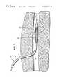
- FIG. 2is a sectional view of a vessel of a patient showing one embodiment of a heat exchange catheter of the present invention inserted therein;
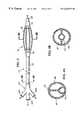
- FIG. 3is an elevational view of an exemplary embodiment of a heat exchange catheter of the present invention having multiple hollow discrete elements for flowing heat transfer medium therethrough on a distal portion of the catheter;
- FIG. 4Ais a sectional view of a proximal end of the catheter of FIG. 3 taken along line 4 A— 4 A;
- FIG. 4Bis a sectional view similar to FIG. 4A of an alternative catheter
- FIG. 5Ais sectional view of the distal heat transfer portion of the catheter of FIG. 3, taken along line 5 — 5 , and showing six heat exchange elements.
- FIG. 5Bis a sectional view, similar to FIG. 5A, of an alternative heat transfer portion of the catheter having three heat exchange elements.
- FIG. 6is a longitudinal sectional view through the distal heat transfer portion of the catheter of FIG. 3 taken along line 6 — 6 of FIG. 5A;
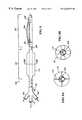
- FIG. 7is a longitudinal sectional view through an alternative embodiment of a heat exchange catheter of the present invention having multiple hollow discrete elements for flowing heat transfer medium therethrough disposed along the entire length of the catheter;
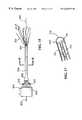
- FIG. 8is elevational view of alternative embodiment of a heat exchange catheter of the present invention having a proximal insulating region, and a distal heat exchange region;
- FIG. 8Ais a sectional view of an insulating region of the catheter of FIG. 8, taken along line 8 A— 8 A, with stand-offs interposed between a central fluid delivery shaft and an outer balloon;
- FIG. 8Bis a sectional view similar to FIG. 8A of an alternative configuration of an insulating region with a plurality of inflatable spacers between the central fluid delivery shaft and an outer sleeve;
- FIG. 9is an elevational view of a distal portion of an alternative embodiment of a heat exchange catheter of the present invention having a plurality of flexible heat exchange elements connected at one end to the catheter;
- FIG. 9Ais a sectional view of a heat exchange element of the catheter of FIG. 9 having a fluid circulation path therein, taken along line 9 A— 9 A;
- FIG. 10Ais a detailed view of a portion of a discrete heat transfer element of the present invention having a helical fin thereon for enhanced heat transfer;
- FIG. 10Bis a detailed view of a portion of a discrete heat exchange element of the present invention having circumferential fins thereon for enhanced heat transfer;
- FIG. 11is an elevational view of a distal portion of an alternative heat exchange catheter of the present invention having a plurality of undulating discrete elements for flowing heat transfer medium therethrough;
- FIG. 12is a sectional view through a hollow heat exchange element of the present invention having a non-circular configuration and greater surface area for heat transfer;
- FIG. 13is a sectional view through an alternative heat exchange catheter of the present intention having a plurality of flexible heat exchange elements connected at one end to the catheter adapted for fluid flow therethrough;
- FIG. 14is a sectional view through one of the flexible heat exchange elements shown in FIG. 13, taken along line 14 — 14 ;
- FIG. 15is a side view of a heat exchange catheter of the invention having coaxial heat exchange elements
- FIG. 16is a cross-sectional view of the proximal manifold for the heat exchange catheter of FIG. 15;
- FIG. 17is an enlarged cross sectional view of the distal tip of one of the coaxial heat exchange elements
- FIG. 18is a cross sectional view of the proximal shaft portion of the heat exchange catheter taken along line 18 — 18 of FIG. 15;
- FIG. 19is a plan view of the faceplate of the proximal manifold of the heat exchange catheter taken along line 19 — 19 of FIG. 16;
- FIG. 20is a plan view of the divider plate of the proximal manifold of the heat exchange catheter shown at 20 — 20 of FIG. 16;
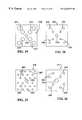
- FIG. 21is a side view of a heat exchange catheter of the invention having single loop heat exchange elements
- FIG. 22is a cross-sectional view of the proximal manifold for the heat exchange catheter of FIG. 21;
- FIG. 23is an enlarged cross-sectional view of the distal tip of a single loop heat exchange element
- FIG. 24is a cross-sectional view of the proximal shaft portion of the heat exchange catheter taken along line 24 — 24 of FIG. 21;
- FIG. 25is a plan view of the faceplate of the proximal manifold of the heat exchange catheter taken along line 25 — 25 of FIG. 22;
- FIG. 26is a plan view of the divider plate of the proximal manifold of the single loop heat exchange catheter taken along line 26 — 26 of FIG. 22 .
- the present inventionprovides an improved heat exchange catheter that provides increased surface area for heat transfer with the respective body fluid without increasing the overall cross-sectional size of the catheter.
- the present inventionis primarily intended to be used in the bloodstream for regulating the patient's blood temperature, those of skill in the art well understand that various other applications for the catheter of the present invention are possible. Indeed, the present invention may have applications beyond controlling the temperature of an internal body fluid, and the claims should not be so limited.
- one or more of the catheters of the present inventionare positioned within a patient's vasculature to exchange heat with the blood in order to regulate the overall body temperature, or to regulate the temperature of a localized region of the patient's body.
- the catheter of the present inventionmay be, for example, suitable for exchanging heat with arterial blood flowing toward the brain to cool the brain, and may thus prevent damage to brain tissue that might otherwise result from a stroke or other injury, or cooling venous blood flowing toward the heart to cool the myocardium to prevent tissue injury that might otherwise occur following an Ml or other similar event.
- the heat exchange catheters disclosed hereinmay be utilized in a heat exchange system suitable for regulating the temperature of a patent or a region of the patient's body.
- a heat exchange catheter system 20utilizing any of the catheters disclosed herein is shown in FIG. 1 .
- the system 20may include a catheter control unit 22 and a heat exchange catheter 24 formed with at least one heat transfer section 44 .
- the heat transfer section or sectionsare located on that portion of the catheter 24 , as illustrated by section 26 , that is inserted into the patient. This insertion portion is less than the full length of the catheter and extends from the location on the catheter just inside the patient, when the catheter is fully inserted, to distal end of the catheter.
- the catheter control unit 22may include a fluid pump 28 for circulating a heat exchange fluid or medium within the catheter 24 , and a heat exchanger component for heating and/or cooling circulating fluids within the heat transfer system 20 .
- a reservoir or fluid bag 30may be connected to the control unit 22 to provide a source of heat transfer fluid such as, saline, blood substitute solution, or other biocompatible fluid.
- a circulatory heat exchange flow channel within the cathetermay be respectively connected to inlet 32 and outlet 34 conduits of the pump 28 for circulation of the heat transfer fluid to cool the flow of fluid within a selected body region.
- a similar arrangementmay be implemented for heating of selected body regions simultaneously or independently from the cooling component of the system.
- the control unit 22may further receive data from a variety of sensors which may be, for example, solid-state thermocouples to provide feedback from the catheter and various sensors to provide patient temperature information representing core temperature or temperature of selected organs or portions of the body.
- sensorsmay include a temperature probe 36 for the brain or head region, a rectal temperature probe 38 , an ear temperature probe 40 , an esophageal temperature probe (not shown), a bladder temperature probe (not shown), and the like.
- control unit 22may direct the heating or cooling of the catheter in response.
- the control unit 22may activate a heat exchanger at a first sensed temperature, and may also de-activate the heat exchanger at a second sensed temperature which may be relatively higher or lower than the first sensed temperature or any other predetermined temperature.
- the control unit 22may of course independently heat or cool selected heat transfer sections to attain desired or preselected temperatures in body regions.
- the controller 22may activate more than one heat exchanger to control temperature at particular regions of the patient's body.
- the controllermight also activate or de-activate other apparatus, for example external heating blankets or the like, in response to sensed temperatures.
- the regulation exercised over the heat transfer catheters or other devicesmay be a simple on-off control, or may be a significantly more sophisticated control scheme including regulating the degree of heating or cooling, ramp rates of heating or cooling, proportional control as the temperature of the heat exchange region or patient approaches a target temperature, or the like.
- the catheter control unit 22may further include a thermoelectric cooler and heater (and associated flow conduits) that are selectively activated to perform both heating and cooling functions with the same or different heat transfer mediums within the closed-loop catheter system.
- a first heat transfer section 42 located on the insertion portion 26 of at least one temperature regulating catheter 24may circulate a cold solution in the immediate head region, or alternatively, within a carotid artery or other blood vessel leading to the brain.
- the head temperaturemay be locally monitored with temperature sensors 36 positioned in a relatively proximate exterior surface of the patient or within selected body regions.
- Another heat transfer section 44 of the catheter 24 also located on the insertion portion 26may circulate a heated solution within a collapsible balloon or otherwise provide heat to other body locations through heat elements or other mechanisms described in accordance with other aspects of the invention. While heat exchange catheter 24 may provide regional hypothermia to the brain region for neuroprotective benefits, other parts of the body may be kept relatively warm so that adverse side effects such as discomfort, shivering, blood coagulopathies, immune deficiencies, and the like, may be avoided or minimized. Warming of the body generally below the neck may be further achieved by insulating or wrapping the lower body in a heating pad or blanket 46 while the head region above the neck is cool. It should be understood of course that multiple heat exchange sections of the catheter 24 may be modified to provide whole body cooling or warming to affect body core temperature.
- FIG. 2illustrates one particular heat exchange catheter 50 of the present invention inserted into a body cavity, in this case a blood vessel BV.
- the blood flow Fis indicated by the arrows directed to the right.
- the heat exchange catheter 50includes an elongate shaft 52 adapted to extend through a puncture wound 54 into the blood vessel BV.
- the catheter 50has a proximal end that remains outside the body and a distal end that is inserted into the body cavity.
- a heat exchange region 56is provided along a distal portion of the catheter 50 which is immersed in the bloodstream.
- the heat exchange region 56corresponds to either of the heat exchange regions 42 or 44 described above with respect to FIG. 1 .
- the illustrated embodimentis shown in more detail in FIGS. 3-6, and includes a plurality of heat exchange elements 58 attached to the catheter shaft 52 providing enhanced heat exchange with the blood, as will be described. Any of the other embodiments disclosed in the present application may be substituted in the heat exchange region 56 .
- the heat exchange catheter 50comprises the aforementioned elongate shaft 52 having a heat exchange region 56 on a distal end, and being provided with a plurality of ports 60 on a proximal end.
- the catheter 50includes a fluid inlet port 60 a , a fluid outlet port 60 b , and a guide wire insertion port 60 c.
- FIG. 4Aillustrates a cross-section of the elongate shaft 52 taken along the line 4 A— 4 A in FIG. 3, wherein three lumen are provided within the shaft.
- a guide wire lumen 62is located generally between two heat transfer fluid circulation lumen 64 and 66 .
- One circulation lumen 64is in fluid communication with the fluid inlet port 60 a
- the other circulation lumen 66is in fluid communication with the fluid outlet port 60 b . It may be readily determined, however, that if flow in the opposite direction is desired, for example to achieve counter-current flow with the blood as described below, either lumen may function as inflow lumen with the other lumen functioning as the outflow lumen. The direction of flow may thus be easily and satisfactorily reversed.
- FIG. 4Billustrates an alternative cross-section of the elongate shaft 52 wherein a centrally disposed guide wire lumen 62 ′ is located between two heat transfer fluid circulation lumen 64 ′ and 66 ′.
- the cross-sectional configuration of the shaft 52desirably extends from a junction with a hub 68 to the distal end 69 of the catheter.
- the extreme distal portionmay consist of just the guide wire lumen or an extension thereof.
- the view in FIG. 3is somewhat abbreviated as indicated by the break lines, and the catheter 50 of this embodiment may be anywhere from 60 to 150 cm in length.
- the heat exchange region 56begins at an outlet manifold 70 and ends at an inlet manifold 72 disposed distally therefrom.
- a plurality of the aforementioned heat exchange elements 58extend adjacent to and generally in parallel with the shaft 52 between the inlet and outlet manifolds 70 , 72 .
- Each element 58is attached on at least one of its ends to the heat exchange region 56 and at least a portion of its length is transversely spaced from the shaft 52 so that when inserted in a fluid body cavity having body fluid therein, the body fluid circumferentially surrounds each heat exchange element.
- each heat exchange element 58is circular, but instead means that when viewed in transverse cross-section, each element is peripherally surrounded by body fluid. This greatly increases the effective heat transfer surface area of the catheter 50 and facilitates heat exchange with the body fluid.
- FIG. 5Aillustrates an alternative embodiment with three heat exchange elements 58 ′. As illustrated, the heat exchange elements 58 are distributed evenly around the circumference of the shaft 52 , but other configurations such as that shown in FIG. 8 are possible.
- the heat exchange catheter 50 of the present inventionprovides a circulatory fluid flow path therein, as best seen in FIG. 6 .
- the circulatory fluid flow pathextends through the elongated heat exchange elements 58 .
- the upper lumen 64functions as a heat exchange medium inflow lumen.
- the lower lumen 66functions as a heat exchange medium outflow lumen. If the direction of heat transfer fluid flow in the heat exchange elements is desired to be in the opposite direction from that illustrated here, however, it may be readily accomplished by reversing the function of these two lumen.
- the circulatory flow path in the heat exchange region 56 of the catheter 50is illustrated in FIG. 6 by the flow arrows 74 and 75 .
- the exchange mediumtravels distally through the inflow lumen 64 until it reaches a port 76 which is in fluid communication with an interior space 78 defined within the inlet manifold 72 .
- Each of the heat exchange elements 58is desirably formed as a hollow tube having an inflow orifice 80 in fluid communication with the interior space 78 .
- each heat exchange element 58has an outflow orifice 82 that is in fluid communication with an interior space 84 defined within the outlet manifold 70 .
- the outflow lumen 66has a port 86 that receives heat exchange medium exiting from the outflow orifices 82 .
- a plug member 88 provided in the outflow lumen 66prevents heat exchange medium from continuing distally past the outlet manifold 70 , while plug members 89 close the distal ends of lumen 64 and 66 .
- heat exchange mediumtravels distally (arrow 74 ) through inflow lumen 64 to exit through the port 76 , enters the space 78 within the inlet manifold 72 , travels within the space to enter the inflow orifices 80 of each of the heat exchange elements 58 , travels proximally (arrows 75 ) through the heat exchange elements, flows from the outflow orifices 82 into the space 84 formed within the outlet manifold 70 , and enters the outflow lumen 66 through the port 86 which carries the medium back to the proximal end of catheter 50 .
- the heat transfer fluid flow through the heat exchange elements 58could be in the distal or proximal direction and, depending on the catheter insertion technique, the flow could be con-current or counter-current to the blood flow direction.
- the inlet and outlet manifolds 70 , 72may be formed by a variety of constructions, a flared, thin-walled jacket being shown.
- the manifolds 70 , 72transition on one end to meet the exterior of the shaft 52 , and are sealed thereto.
- the open area within each manifoldreceives the ends of the heat exchange elements 58 , and a potting compound 90 which may be a suitable adhesive, seals the interior spaces 78 and 84 from the exterior of the circulatory flow path.
- the heat exchange elements 58are thus sealed between the respective manifolds 70 , 72 and the potting compound in a fluid tight manner.
- other constructionssuch as a molded polymer or shrink-wrap material may be substituted for the flared jacket, and other constructions such as a sealing ring may be substituted for the potting compound.
- the heat exchange elements 58are illustrated as being bowed outward slightly from the catheter shaft 52 . This arrangement ensures that the elements 58 are surrounded by body fluid during use, such as seen in FIG. 2, so as to greatly enhance heat transfer capacity for a given fluid flow rate. That is, the heat exchange medium is divided at the distal end of the catheter and flows proximally through a plurality of parallel paths, each of which passes through heat exchange elements 58 each having a continuous external surface. This arrangement is best illustrated in FIGS. 5A and 5B. In addition, some heat exchange takes place between the inflow lumen 64 and the external body fluid, through the wall of the shaft 52 .
- a spring member 92is desirably connected to a radially inner portion of each heat exchange element 58 and is cantilevered toward and into contact with the shaft 52 .
- external forcesmay cause the heat exchange elements 58 to be pressed inward, compressing the spring member 92 which slides against the shaft 52 .
- the spring member 92expands to move the heat exchange elements 58 radially outward into optimum heat exchange position.
- the spring members 92have a relatively low profile in the blood flow path, and thus minimize any obstruction to blood flow.
- Another construction that would assure separation in use between the heat exchange elements 58 and shaft 52is to provide thin-walled, inflatable tubes as the heat exchange elements.
- the elementsare slightly longer than the distance between the inlet and outlet manifolds, 70 , 72 .
- the elements 58When the elements 58 are collapsed, for example upon insertion into the patient, they will fold down flat against the shaft to provide a low profile.
- theyWhen they are inflated, for example by pressurized and flowing heat exchange fluid in use, they will bow out away from the shaft. See, for example, FIG. 3 and FIG. 8 .
- the distance between the inlet and outlet manifolds 70 , 72may be variable via a pull-wire (not shown) or other such expedient that acts on the shaft 52 .
- the shaft 52may be constructed in telescoping sections, or may be bendable, so that the distance between the inlet and outlet manifolds 70 , 72 can be shortened upon actuation of the pull-wire. In this manner, the elements 58 initially lie flat against the elongated shaft 52 but are then caused to bow outward away from the shortened shaft.
- FIG. 7An alternative embodiment of a heat exchange catheter 100 of the present invention is seen in FIG. 7 .
- the catheter 100is similar to the catheter 50 described previously in that a heat exchange medium circulation path is provided therein, and a plurality of elongated heat exchange elements 102 , discrete from a catheter shaft 104 , form a portion of the circulation path.
- the heat exchange region 106extends along the entire length of the catheter shaft 104 .
- Each of the heat exchange elements 102is preferably formed as an elongate hollow filament.
- the heat exchange catheter 100includes a fluid circulation path therein comprising an inner lumen or lumen 108 formed within the inner shaft 104 , a space 110 formed within a manifold 112 provided at the distal end of the catheter, and the hollow lumen of the heat exchange elements 102 are in fluid communication with that space 110 .
- the proximal end of the inner shaft 104fits within an inlet fitting 114 having an inner chamber 116 that communicates with the lumen 108 .
- the inner shaft 104extends through a chamber 118 formed in an outlet fitting 120 , and the proximal ends of the heat exchange elements 102 are sealed in the fluid communication with the chamber 118 using potting compound 122 .
- fluid entering the chamber 116is directed into the lumen 108 and travels distally through the catheter 100 as indicated by arrows 126 .
- the fluidis redirected 180 degrees into the hollow lumen of the heat exchange elements 102 .
- potting compound 128is used seal the distal ends of the elements 102 within the space 110 .
- the fluidtravels proximally through the elements 102 , as indicated by arrows 130 , and exits the heat exchange elements into the chamber 118 to be removed from the chamber as indicated by arrow 132 .
- the advantage of providing a heat-exchange region 106 along the entire length of catheter 100is the capacity for greater heat exchange with the body fluid.
- the catheter 100 having a heat exchange region 106 along 100 percent of its lengthmay more effectively provide whole body heating or cooling.
- some heatmight be transferred to or from the body fluid through the proximal portion of the catheter that is not part of the heat-exchange region.
- the entire catheteris designed to exchange heat with the body fluid.
- FIG. 8illustrates a further embodiment of a heat exchange catheter 150 having a heat exchange region 152 on its distal portion, and an insulating region 154 on its proximal portion.
- the heat exchange region 152 and insulating region 154are approximately equal in length, both being about 50 percent of the entire length of the catheter 150 .
- the insulating region 154is substantially longer than the heat exchange region 152 , and preferably at least 75 percent of the length of the catheter 150 .
- the combined length of the heat exchange region 152 and insulating region 154is approximately equal to the entire length of the catheter 100 .
- One specific exampleis an insulating region that extends about 85-90% of the total catheter length, and a heat exchange region that extends the remaining 10-15%.
- various alternative configurationsare contemplated, including intermittent and interspersed insulating and heat exchange regions.
- the catheter 150 in FIG. 8includes a heat exchange medium inlet port 160 and a heat exchange medium outlet port 162 .
- a fluid circulation path(not shown) is provided within an elongate shaft 164 .
- a plurality of elongated heat exchange elements 166are provided parallel to but spaced from the shaft 164 in the heat exchange region 152 .
- the heat exchange elements 166are hollow filaments that form separate parts of the fluid circulation path within the catheter 150 .
- a distal manifold 168receives the distal ends of the heat exchange elements 166
- a proximal manifold 170receives the proximal ends.
- the manifolds 168 , 170define fluid flow spaces therein; a space within the distal manifold 168 being in fluid communication with the inlet port 160 , and a space within the proximal manifold 170 being in fluid communication with the outlet port 162 . In this manner, a liquid heat exchange medium flows into the port 160 and to the distal end of the catheter 150 before returning to the outlet port 162 via the hollow heat exchange elements 166 .
- the insulating region 154includes an insulating member 172 disposed longitudinally about the shaft 164 .
- the insulating member 172may be a variety of constructions, including a solid sleeve or a fluid-filled balloon.
- the insulating member 172comprises an inflatable balloon having an interior space in communication with an inflation port 173 .
- a suitable insulating fluidsuch as nitrogen gas or carbon dioxide gas, inflates the balloon 172 away from the side of the shaft 164 . In this manner, even if the entire length of the shaft 164 is immersed in a body fluid, only the heat exchange region 152 transfers heat efficiently to or from the body fluid.
- the shaft 164may be centered within and held spaced from the insulating member 172 , for example by collapsible stand-offs 175 , to prevent the shaft from resting against the side of the inflated insulating member and comprising the insulating capacity of the insulating member.
- the stand-offs 175may be relatively thin and flexible so that when the insulating member is collapsed for insertion and removal, they fold down against the shaft without adding significantly to the overall catheter profile.
- the insulating membercould be a multi-lumen, thin-walled balloon with a central lumen into which the shaft 164 is inserted, and inflatable insulating lumens 179 surrounding the central lumen.
- An insulating sleeve 181may surround the entire insulating region.
- FIG. 8having an insulating region and a heat transfer region may be particularly useful in cooling blood flowing to the brain to regionally direct the cooling effect of the catheter.
- the effectiveness of cooling or heating the blooddepends in part upon the difference in temperature between the surface of the heat exchange region in contact with the blood, and the temperature of the blood. This difference in temperature is referred to herein as ⁇ T.
- the catheter 150can be inserted in, for example the femoral artery, passed through the vasculature, for example up the aorta, so that the heat exchange region 152 is located in the carotid artery.
- the heat exchange fluidis circulated through the catheter 150 , and remains cool until it reaches the heat exchange region 152 by virtue of the insulating region 154 , and thus a maximum ⁇ T is maintained. Without the insulating region 154 , the effectiveness of the heat exchange medium is diminished, and significantly less cooling of the blood at the desired location, in this case the carotid artery, may result.
- the regional effect of the coolingmay also be compromised by the exchange of heat with blood that does not subsequently circulate to the desired region of the body.
- the insulating region 154prevents the cold heat exchange fluid from exchanging heat with the blood within the arterial system in the femoral artery and the ascending aorta, which blood would circulate to the trunk and legs of the patient.
- This cooling of blood which then circulates to other regions of the bodycan result in a general cooling of the entire body. While this general cooling may be desirable in some applications, it may be undesirable in other applications such as applications wherein it is intended to effect regional or localized cooling of the heart or the brain. In this regard, such general cooling can result in discomfort, such as shivering, in the patient, or other negative side effects of whole body hypothermia that might be avoided by regional cooling.
- the heat exchange elementshave been described as hollow filaments forming a portion of a fluid flow path and attached at both ends to the catheter shaft.
- the present inventionis of a more general nature, however, in that the multiple and distinct heat exchange elements need not be attached at both ends to the shaft, but may instead be constrained along a portion of its length with respect to the shaft so that a free end thereof is permitted to drift freely within the body fluid.
- the freely floating elementsdesirably define an internal “cul-de-sac” fluid flow path.
- FIG. 9illustrates a heat exchange catheter 180 in accordance with the present invention having an elongate shaft 182 and a plurality of heat exchange elements 184 attached thereto.
- the heat exchange elements 184are attached at distal ends to the shaft 182 and are generally free-floating at distal tips 186 .
- These elements 184are preferably flexible and collapsible so as to compress against the exterior of the shaft 182 to provide a low profile during insertion and removal of catheter 180 .
- the flexible nature of the elements 184facilitates location in and passage through tortuous passages, and minimization of restriction to flow of blood through the vessels when inflated.
- the elements 184 along any one catheter 180may be of different lengths.
- the catheter 180further may include a proximal insulating member 188 , which may be a single- or multi-lumen balloon as described above.
- the heat exchange elements 184can be provided in the variety of constructions. Each of the heat-exchange elements 184 may provide fluid circulation therein.
- the cross-sectional view of FIG. 9Aillustrates the heat exchange element 184 having a fluid inlet path 190 and a parallel fluid outlet path 192 .
- the fluid paths 190 , 192are placed in fluid communication with a main circulation path provided within the shaft 182 .
- the heat exchange elements 184are somewhat similar to the elements 58 described above with respect to the first embodiment, but are somewhat freer to float within the body fluid.
- the elements 184being attached at only one end permits them to more freely migrate around circumference of the shaft 182 when the catheter 180 is advanced through tortuous passage ways. A further embodiment of this nature is seen in FIGS. 13 and 14.
- each of the elementsmay be provided with a flow disrupting rib or other discontinuity. It is a well-known principle of heat exchange that reducing the laminar boundary layer around an object in a fluid flow path increases the potential heat transfer between that object and the fluid.
- FIG. 10Aillustrates a tubular heat exchange element 200 provided with a helical rib 202 thereon.
- Other such configurationsare possible, including circumferentially oriented ribs 204 on a heat exchange element 206 , as seen in FIG. 10 B.
- FIG. 11illustrates a heat exchange region 210 on a catheter of the present invention wherein a plurality of undulating heat exchange elements 212 extend from a distal manifold 214 to a proximal manifold 216 provided on a shaft 218 .
- the elements 212extend in a non-linear path with at least one point of inflection.
- This configurationprovides greater surface area for each heat exchange element 212 than the shallow convexity of elements 58 , 102 , and 166 , previously described.
- each element 212is located generally parallel to but spaced from the main shaft 218 permits them to compress inward and/or migrate around the circumference of the shaft when passing the catheter through narrow or tortuous body cavities.
- FIG. 12illustrates, in cross-section, a heat exchange element 220 having a plurality of alternating outwardly projecting regions 222 and grooves 224 .
- the overall cross-sectional footprintif you will, fits within an imaginary circle 226 , but has a greater exterior surface area.
- FIGS. 13 and 14An alternative construction for the heat exchange elements is shown in FIGS. 13 and 14.
- a catheter shaft 240contains an inlet fluid flow lumen 242 and an outlet fluid flow lumen 244 .
- a plurality of heat exchange elements 246attach at only one end along the length of the shaft 240 so that they may float freely in surrounding body fluid.
- Each heat exchange element 246comprises an outer tubule 248 surrounding an inner tubule 250 .
- the distal end of the outer tubule 248is closed and the distal end of the inner tubule 250 is open and terminates short of the distal end of the outer tubule.
- the inner tubules 250define lumen therein that are in fluid communication with the inlet lumen 242 .
- the outlet lumen 244is in fluid communication with the annular space between the inner tubule 250 and outer tubule 248 .
- heat transfer fluid traveling through the inlet lumen 242 of the shaft of the catheterenters the inlet tubule lumen, as indicated by arrows 252 , and flows between the inner and outer tubules and into the outlet lumen 244 of the shaft, as indicated by arrows 254 .
- the heat exchange medium circulation pathin this case includes so-called cul-de-sac heat exchange elements.
- the outer surface of the outlet tubuleis surrounded by body fluid, for example blood, and as heat transfer fluid circulates through the tubules, heat may be transferred between the heat transfer fluid and the body fluid.
- body fluidfor example blood
- FIGS. 15-20A still further alternative construction for the heat exchange elements is shown in FIGS. 15-20.
- This embodimentincludes a proximal manifold 300 and a plurality of heat exchange elements 302 , wherein proximal portions of the individual heat exchange elements 302 are bundled or positioned within a shaft or sleeve 306 . Distal portions of the heat exchange elements 302 protrude out of and freely extend beyond the distal end of the sleeve 306 .
- the catheterincludes a guidewire tube 304 that extends through the proximal manifold 300 and beyond the distal ends of the heat exchange elements 302 .
- the sleeve 306may comprise a flexible tubular structure that substantially surrounds the multiple heat exchange elements 302 (that comprise flexible tubes) and the guidewire tube 304 , along substantially the entire length of the catheter.
- the portions of the heat exchange elements that protrude beyond the distal end of the sleeve 304define the heat exchange region of this particular embodiment of the invention.
- the tubular sleeve 306may be flared at a proximal end 308 to facilitate convergence of the multiple heat exchange elements 302 into a single, low-profile tube.
- the heat exchange elements 302are unconstrained and float freely with the body fluid beyond a distal end 310 of the tubular sleeve 306 .
- the embodiment illustratedshows eight heat exchange elements 302 , although other numbers are possible.
- the guidewire tube 304is generally stiffer than the heat exchange elements 302 .
- a temporary attachment means(not shown) may initially be provided to couple the loose portions of the heat exchange elements 302 and the guidewire tube 304 or a temporary adhesive releasably attaching the heat exchange elements to the guidewire tube.
- Such attachment meansmay be in the form of an elastomeric band around all of the heat exchange elements 302 and the guidewire tube 304 .
- Such a weak, temporary attachmentmay be overcome when the elements 302 are inflated during operation of the catheter, or may be severed by other suitable means.
- the heat exchange elements 302comprise coaxial tubes, each having an inner lumen 312 and an outer lumen 314 .
- the outer lumen 314is closed, and the inner lumen terminates short of this distal end.
- the flow arrowsshow heat exchange medium passing distally through the inner lumen 312 , and being redirected at the distal end 316 to travel proximally through the outer lumen 314 .
- the proximal manifold 300comprises a container generally divided into two equal chambers; an inlet chamber 318 , and an outlet chamber 320 .
- the inlet chamber 318has a fluid inlet port 322
- the outlet chamber 320has a fluid outlet port 324 .
- the two chambers 318 , 320are separated by a divider plate 326 .
- Each of the heat exchange elements 302passes through a front plate 328 of the manifold 300 .
- the inner lumen 312are defined within input tubes 330 terminating in the inlet chamber 318 .
- the outer lumen 314are defined within output tubes 332 terminating in the outlet chamber 320 .
- the input and output tubes 330 , 332pass through holes 334 formed in the front plate 328 , as seen in FIG. 19 . Each of the holes 334 fluidly seals around the tubes 330 , 332 .
- a central hole 335 for passage of the guidewire tube 304is also provided in the front plate 328 .
- the guidewire tube 304extends in a sealed manner through the central hole 335 .
- the divider plate 326includes a central hole 338 fluidly sealed around the guidewire tube 304 .
- the guidewire tube 304continues through a single hole 340 provided in the back plate of the manifold 300 .
- Each input tube 330passes through a hole 336 in the divider plate 326 , and is fluidly sealed with respect thereto.
- the catheterIn use, the catheter is inserted into a blood vessel and heat exchange fluid is introduced through the inlet port 322 and into the inflow chamber 318 .
- the heat exchange fluidthen passes into the open proximal ends of each of the inlet tubes 330 , and into the inner lumen 312 of each of the heat exchange elements 302 .
- the fluidpasses along the length of each of the heat exchange elements 302 until it is re-directed at the distal end 316 into the outer lumen 314 .
- the fluidthen travels proximally through the outer lumen 314 , as seen FIG. 17, until it reaches the open proximal ends of each of the outlet tubes 332 .
- heat exchange elements 302are initially in a collapsed configuration, the flow of heat exchange fluid inflates them and may cause severance of an attachment means and subsequent separation of each of the elements.
- the fluidultimately passes into the outlet chamber 320 and exits the manifold 300 through the outlet port 324 .
- heat exchange fluidmay be circulated through the heat exchange catheter.
- the heat exchange fluidreturns proximally through the outer lumen 314 , it exchanges heat with blood flowing past the surface of the elements through the outer wall of the heat exchange elements 302 .
- the inlet flow of heat exchange fluidis desirably through the inner lumen 312 and the outlet flow is desirably through the outer lumen 314 .
- This flow arrangementis preferred for the catheterwith free-floating heat exchange elements on the distal end, because even if the blood flows distal to proximal, the elements tend to prolapse and float backward toward the proximal end of the catheter. In such a configuration, counter flow is achieved if the heat exchange fluid is flowing back out of the catheter through the outer lumen 314 .
- a heat exchange catheter 350 of the present inventionincludes a plurality of heat exchange elements that are formed of a loop of single lumen tubing that extends the entire length of the catheter.
- the inlet end of each of the single lumen tubesis open to an inlet reservoir of a manifold, and the outlet end is open to the outlet reservoir.
- Heat exchange fluidcirculates along the entire length of each of the heat exchange elements.
- a single loop heat exchange catheter 350comprises a proximal manifold 352 , a plurality of coaxial heat exchange elements 354 , a guidewire tube 356 , and a proximal tubular sleeve 358 that surrounds the heat exchange elements in the proximal region of catheter.
- the catheter 350 illustratedshows eight such heat exchange elements 354 , each comprising loops of long single lumen tubes. Of course, those of skill in the art will understand that the number of heat exchange elements may be varied.
- the proximal end 360 of the tubular sleeve 358may be flared to facilitate a convergence of a the multiple heat exchange elements 354 into a single, lower profile tube.
- the heat exchange elements 354are unconstrained and may float freely.
- the guide wire tube 356is generally stiffer than the heat exchange elements 354 , and a loose attachment (not shown) may temporarily be formed therebetween.
- an attachment meanssuch as elastomeric band around all of the heat exchange elements 354 and the guidewire tube 356 may be used.
- any weak, temporary attachment means that can be overcome when the elements 354 are inflatedcan be substituted.
- the proximal manifold 352defines within two reservoirs; an inflow reservoir 368 an outflow reservoir 370 .
- a divider plate 372separates the two reservoirs 368 , 370 .
- An inflow port 374communicates with the inflow reservoir 368
- on outflow port 376communicates with the outflow reservoir 370 .
- a front plate 378forms the front surface of the manifold 352 , as seen in plan view in FIG. 25 .
- the heat exchange elements 354comprise long, thin-walled tubes, each defining a single lumen 364 therein. Each tube has an open end 366 positioned in the inflow reservoir 368 and extends distally through sealed apertures 380 in the divider plate 372 (FIG. 26 ). The tubes pass through the outflow reservoir 370 and through sealed apertures 382 in the front plate 378 (FIG. 25 ). The tubes continue distally, converging in the flared portion 360 of the tubular sleeve 358 , and emerging from a distal end 362 . Each of the heat exchange elements 354 extends for some distance to a distal bend 384 , seen in FIG. 23 . The distal flow of heat exchange fluid is thus re-directed proximally at the distal bend 384 . The return tube again passes through one of the apertures 382 in the front plate 378 , and terminates in the outflow reservoir 370 .
- a guidewire tube 356passes entirely through the manifold 352 , extending through a proximal guidewire hole 388 , a central aperture 390 in the divider plate 372 , and a central aperture 392 in the front plate 378 .
- the guidewire tube 356is sealed from both reservoirs 368 , 370 in the manifold 352 .
- heat transfer fluid(represented by the arrows in the various FIGURES) is introduced into the inflow reservoir 368 through the inflow port 374 .
- the pressurized fluidpasses into the open ends of each of the heat exchange element tubes 354 , flows the entire length of the tube and is redirected at the bend 384 , and then flows proximally, emptying into the outflow reservoir 370 .
- the fluidis then exhausted through the outlet port 376 .
- the direction of flowmay be easily reversed without altering the basic principles of the invention. In this embodiment, however, the heat exchange fluid will be flowing in both directions in a tube in contact with the blood flow, and therefore both co- and counter-current flow will exist. Thus, the direction of flow through the tubes becomes less significant than in the coaxial arrangement described above.
- the heat exchange elements of the present inventionmay be formed from a variety of materials, the main consideration being biocompatibility.
- the elementsare fluid impermeable, preferably some form of polymer, and flexible.
- One particularly useful materialis polyethylene terephthalate (PET) which can be extruded and blown to form thin-walled hollow filaments.
- the catheterFor example, if the catheter is inserted into the inferior vena cava through a jugular vein incision, the blood would flow over the heat exchange region from the distal end toward the proximal end of the catheter (i.e., retrograde flow), whereas if the catheter is inserted into the inferior vena cava from a femoral vein incision, the blood would flow past the heat exchange region from proximal toward distal (i.e., antegrade flow).
- the inlet and outlet lumen of the shaftmay be reversed without departing from the invention as described. Similarly other variations of the embodiments described are anticipated within the scope of the invention as claimed.
Landscapes
- Health & Medical Sciences (AREA)
- Animal Behavior & Ethology (AREA)
- Veterinary Medicine (AREA)
- Engineering & Computer Science (AREA)
- Biomedical Technology (AREA)
- Heart & Thoracic Surgery (AREA)
- Vascular Medicine (AREA)
- Thermal Sciences (AREA)
- General Health & Medical Sciences (AREA)
- Life Sciences & Earth Sciences (AREA)
- Public Health (AREA)
- Physics & Mathematics (AREA)
- Thermotherapy And Cooling Therapy Devices (AREA)
- Media Introduction/Drainage Providing Device (AREA)
- External Artificial Organs (AREA)
- Separation By Low-Temperature Treatments (AREA)
Abstract
Description
Claims (63)
Priority Applications (12)
| Application Number | Priority Date | Filing Date | Title |
|---|---|---|---|
| US09/378,578US6264679B1 (en) | 1999-08-20 | 1999-08-20 | Heat exchange catheter with discrete heat exchange elements |
| AT00952284TATE348574T1 (en) | 1999-08-20 | 2000-07-31 | HEAT EXCHANGE CATHETER WITH DISCRETE HEAT EXCHANGE ELEMENTS |
| CA2382328ACA2382328C (en) | 1999-08-20 | 2000-07-31 | Heat exchange catheter with discrete heat exchange elements |
| PCT/US2000/020684WO2001013809A1 (en) | 1999-08-20 | 2000-07-31 | Heat exchange catheter with discrete heat exchange elements |
| JP2001517953AJP4610825B2 (en) | 1999-08-20 | 2000-07-31 | Heat exchange catheter with a separate heat exchange element |
| DE60032491TDE60032491T2 (en) | 1999-08-20 | 2000-07-31 | HEAT EXCHANGERS WITH DISCRETE HEAT EXCHANGERS |
| EP00952284AEP1207801B1 (en) | 1999-08-20 | 2000-07-31 | Heat exchange catheter with discrete heat exchange elements |
| ES00952284TES2278624T3 (en) | 1999-08-20 | 2000-07-31 | CATHETER FOR THERMAL EXCHANGE WITH A PLURALITY OF THERMAL EXCHANGE ELEMENTS. |
| AU65010/00AAU6501000A (en) | 1999-08-20 | 2000-07-31 | Heat exchange catheter with discrete heat exchange elements |
| US09/907,799US6702840B2 (en) | 1999-08-20 | 2001-07-18 | Heat exchange catheter with discrete heat exchange elements |
| US10/727,084US20040167593A1 (en) | 1999-08-20 | 2003-12-03 | Heat exchange catheter with discrete heat exchange elements |
| JP2010132357AJP2010207619A (en) | 1999-08-20 | 2010-06-09 | Heat exchange catheter with discrete heat exchange element |
Applications Claiming Priority (1)
| Application Number | Priority Date | Filing Date | Title |
|---|---|---|---|
| US09/378,578US6264679B1 (en) | 1999-08-20 | 1999-08-20 | Heat exchange catheter with discrete heat exchange elements |
Related Child Applications (2)
| Application Number | Title | Priority Date | Filing Date |
|---|---|---|---|
| US09/907,799ContinuationUS6702840B2 (en) | 1999-08-20 | 2001-07-18 | Heat exchange catheter with discrete heat exchange elements |
| US09/907,779ContinuationUS20030053669A1 (en) | 1999-08-20 | 2001-07-18 | Magnetic resonance angiography method and apparatus |
Publications (1)
| Publication Number | Publication Date |
|---|---|
| US6264679B1true US6264679B1 (en) | 2001-07-24 |
Family
ID=23493688
Family Applications (2)
| Application Number | Title | Priority Date | Filing Date |
|---|---|---|---|
| US09/378,578Expired - LifetimeUS6264679B1 (en) | 1999-08-20 | 1999-08-20 | Heat exchange catheter with discrete heat exchange elements |
| US09/907,799Expired - LifetimeUS6702840B2 (en) | 1999-08-20 | 2001-07-18 | Heat exchange catheter with discrete heat exchange elements |
Family Applications After (1)
| Application Number | Title | Priority Date | Filing Date |
|---|---|---|---|
| US09/907,799Expired - LifetimeUS6702840B2 (en) | 1999-08-20 | 2001-07-18 | Heat exchange catheter with discrete heat exchange elements |
Country Status (9)
| Country | Link |
|---|---|
| US (2) | US6264679B1 (en) |
| EP (1) | EP1207801B1 (en) |
| JP (2) | JP4610825B2 (en) |
| AT (1) | ATE348574T1 (en) |
| AU (1) | AU6501000A (en) |
| CA (1) | CA2382328C (en) |
| DE (1) | DE60032491T2 (en) |
| ES (1) | ES2278624T3 (en) |
| WO (1) | WO2001013809A1 (en) |
Cited By (114)
| Publication number | Priority date | Publication date | Assignee | Title |
|---|---|---|---|---|
| US6379378B1 (en)* | 2000-03-03 | 2002-04-30 | Innercool Therapies, Inc. | Lumen design for catheter |
| US6451045B1 (en)* | 2001-02-22 | 2002-09-17 | Alsius Corporation | Heat exchange catheter having a helically wrapped heat exchanger |
| US6475231B2 (en) | 1998-03-24 | 2002-11-05 | Innercool Therapies, Inc. | Method and device for applications of selective organ cooling |
| US6491039B1 (en) | 1998-01-23 | 2002-12-10 | Innercool Therapies, Inc. | Medical procedure |
| US20020193853A1 (en)* | 1999-03-11 | 2002-12-19 | Alsius Corp. | Method and system for treating cardiac arrest using hypothermia |
| WO2003015673A1 (en)* | 2001-08-15 | 2003-02-27 | Innercool Therapies, Inc. | System and method for patient temperature control employing temperature projection algorithm |
| US6533804B2 (en) | 1998-01-23 | 2003-03-18 | Innercool Therapies, Inc. | Inflatable catheter for selective organ heating and cooling and method of using the same |
| US20030065922A1 (en)* | 2001-09-28 | 2003-04-03 | Fredlund John R. | System and method of authenticating a digitally captured image |
| US6576002B2 (en) | 1998-03-24 | 2003-06-10 | Innercool Therapies, Inc. | Isolated selective organ cooling method and apparatus |
| US6585752B2 (en) | 1998-06-23 | 2003-07-01 | Innercool Therapies, Inc. | Fever regulation method and apparatus |
| US6589271B1 (en) | 1998-04-21 | 2003-07-08 | Alsius Corporations | Indwelling heat exchange catheter |
| US6592612B1 (en)* | 2000-05-04 | 2003-07-15 | Cardeon Corporation | Method and apparatus for providing heat exchange within a catheter body |
| US6595967B2 (en) | 2001-02-01 | 2003-07-22 | Innercool Therapies, Inc. | Collapsible guidewire lumen |
| WO2003006085A3 (en)* | 2001-07-13 | 2003-07-24 | Radiant Medical Inc | Catheter system with on-board temperature probe |
| WO2003059218A1 (en)* | 2002-01-09 | 2003-07-24 | Alsius Corporation | Method and system for therapeutic hypothermia |
| US6599312B2 (en) | 1998-03-24 | 2003-07-29 | Innercool Therapies, Inc. | Isolated selective organ cooling apparatus |
| US6602276B2 (en) | 1998-03-31 | 2003-08-05 | Innercool Therapies, Inc. | Method and device for performing cooling- or cryo-therapies for, e.g., angioplasty with reduced restenosis or pulmonary vein cell necrosis to inhibit atrial fibrillation |
| US20030167034A1 (en)* | 1999-09-15 | 2003-09-04 | Balding David P. | Automatic fever abatement applications |
| US6620131B2 (en)* | 1999-02-19 | 2003-09-16 | Alsius Corporation | Dual balloon central venous line catheter temperature control system |
| WO2003013344A3 (en)* | 2001-08-09 | 2003-09-25 | Innercool Therapies Inc | Method and device for patient temperature control employing optimized rewarming |
| US6641603B2 (en) | 2001-04-13 | 2003-11-04 | Alsius Corporation | Heat exchange catheter having helically wound reinforcement |
| US6648906B2 (en) | 2000-04-06 | 2003-11-18 | Innercool Therapies, Inc. | Method and apparatus for regulating patient temperature by irrigating the bladder with a fluid |
| US6660028B2 (en) | 2000-06-02 | 2003-12-09 | Innercool Therapies, Inc. | Method for determining the effective thermal mass of a body or organ using a cooling catheter |
| US6676690B2 (en) | 1999-10-07 | 2004-01-13 | Innercool Therapies, Inc. | Inflatable heat transfer apparatus |
| US6676688B2 (en) | 1998-01-23 | 2004-01-13 | Innercool Therapies, Inc. | Method of making selective organ cooling catheter |
| US6685732B2 (en) | 1998-03-31 | 2004-02-03 | Innercool Therapies, Inc. | Method and device for performing cooling- or cryo-therapies for, e.g., angioplasty with reduced restenosis or pulmonary vein cell necrosis to inhibit atrial fibrillation employing microporous balloon |
| US6685733B1 (en) | 2002-04-10 | 2004-02-03 | Radiant Medical, Inc. | Methods and systems for reducing substance-induced renal damage |
| US6692488B2 (en) | 1998-01-23 | 2004-02-17 | Innercool Therapies, Inc. | Apparatus for cell necrosis |
| US20040044388A1 (en)* | 2002-08-30 | 2004-03-04 | Alsius Corporation | Intravascular temperature control catheter |
| US6702841B2 (en) | 1998-01-23 | 2004-03-09 | Innercool Therapies, Inc. | Method of manufacturing a heat transfer element for in vivo cooling |
| US6702842B2 (en) | 1998-01-23 | 2004-03-09 | Innercool Therapies, Inc. | Selective organ cooling apparatus and method |
| US20040049177A1 (en)* | 2000-10-24 | 2004-03-11 | Roni Zvuloni | Multiple cryoprobe apparatus and method |
| US6709448B2 (en) | 2001-04-13 | 2004-03-23 | Alsius Corporation | Open core heat exchange catheter, system and method |
| US6719779B2 (en) | 2000-11-07 | 2004-04-13 | Innercool Therapies, Inc. | Circulation set for temperature-controlled catheter and method of using the same |
| US6719723B2 (en) | 2000-12-06 | 2004-04-13 | Innercool Therapies, Inc. | Multipurpose catheter assembly |
| US6726710B2 (en) | 1999-08-16 | 2004-04-27 | Alsius Corporation | Method and system for treating cardiac arrest using hypothermia |
| US6749625B2 (en) | 2002-08-30 | 2004-06-15 | Alsius Corporation | Intravascular temperature control catheter |
| US20040133256A1 (en)* | 2001-05-31 | 2004-07-08 | Radiant Medical, Inc. | Heat transfer catheter with elastic fluid lumens |
| US20040199114A1 (en)* | 2003-04-01 | 2004-10-07 | Alsius Corporation | Intravascular heat exchange catheter with tissue preservative |
| US20040210285A1 (en)* | 2002-04-04 | 2004-10-21 | Steven Yon | Method of manufacturing a heat transfer element for in vivo cooling without undercuts |
| US6811551B2 (en)* | 1999-12-14 | 2004-11-02 | Radiant Medical, Inc. | Method for reducing myocardial infarct by application of intravascular hypothermia |
| US6830581B2 (en) | 1999-02-09 | 2004-12-14 | Innercool Therspies, Inc. | Method and device for patient temperature control employing optimized rewarming |
| US20050043579A1 (en)* | 2001-10-26 | 2005-02-24 | Radiant Medical, Inc. | Intra-aortic balloon counterpulsation with concurrent hypothermia |
| US6866638B2 (en) | 2002-08-12 | 2005-03-15 | Radiant Medical, Inc. | Temperature sensing system with retrograde sensor |
| US6869440B2 (en) | 1999-02-09 | 2005-03-22 | Innercool Therapies, Inc. | Method and apparatus for patient temperature control employing administration of anti-shivering agents |
| US20050061473A1 (en)* | 2003-09-22 | 2005-03-24 | Coolhead Technologies, Inc. | Flexible heat exchangers |
| US6905494B2 (en) | 1998-03-31 | 2005-06-14 | Innercool Therapies, Inc. | Method and device for performing cooling- or cryo-therapies for, e.g., angioplasty with reduced restenosis or pulmonary vein cell necrosis to inhibit atrial fibrillation employing tissue protection |
| US20050209658A1 (en)* | 1998-08-24 | 2005-09-22 | Radiant Medical, Inc. | Disposable cassette for intravenous heat exchange catheter |
| US20050224085A1 (en)* | 2000-10-24 | 2005-10-13 | Roni Zvuloni | Apparatus and method for compressing a gas, and cryosurgery system and method utilizing same |
| US20050251124A1 (en)* | 2001-05-21 | 2005-11-10 | Galil Medical Ltd. | Apparatus and method for cryosurgery within a body cavity |
| US6974463B2 (en) | 1999-02-09 | 2005-12-13 | Innercool Therapies, Inc. | System and method for patient temperature control employing temperature projection algorithm |
| US7001378B2 (en) | 1998-03-31 | 2006-02-21 | Innercool Therapies, Inc. | Method and device for performing cooling or cryo-therapies, for, e.g., angioplasty with reduced restenosis or pulmonary vein cell necrosis to inhibit atrial fibrillation employing tissue protection |
| US7018399B2 (en) | 1998-06-23 | 2006-03-28 | Innercool Therapies, Inc. | Method of making selective organ cooling catheter |
| US20060095104A1 (en)* | 1999-02-09 | 2006-05-04 | Michael Magers | System and method for patient temperature control employing temperature projection algorithm |
| US20060190066A1 (en)* | 2005-02-23 | 2006-08-24 | Worthen William J | System and method for bringing hypothermia rapidly onboard |
| WO2006091284A1 (en) | 2005-02-23 | 2006-08-31 | Alsius Corporation | System and method for bringing hypothermia rapidly onboard |
| US20060282039A1 (en)* | 2005-06-09 | 2006-12-14 | Endocare, Inc. | Heat exchange catheter with multi-lumen tube having a fluid return passageway |
| US20060278093A1 (en)* | 2004-01-13 | 2006-12-14 | Eytan Biderman | Feeding formula appliance |
| US20070005050A1 (en)* | 2005-06-09 | 2007-01-04 | Endocare, Inc. | Heat exchange catheter and method of use |
| US20070005121A1 (en)* | 2002-04-29 | 2007-01-04 | Rohit Khanna | Central nervous system cooling catheter |
| US7181927B2 (en) | 2005-07-01 | 2007-02-27 | Alsius Corporation | Primary heat exchanger for patient temperature control |
| US20070088247A1 (en)* | 2000-10-24 | 2007-04-19 | Galil Medical Ltd. | Apparatus and method for thermal ablation of uterine fibroids |
| US7220257B1 (en)* | 2000-07-25 | 2007-05-22 | Scimed Life Systems, Inc. | Cryotreatment device and method |
| US20070213793A1 (en)* | 2001-08-06 | 2007-09-13 | Radiant Medical, Inc. | Use of endovascular hypothermia in organ and/or tissue transplantations |
| US7278984B2 (en) | 2002-12-31 | 2007-10-09 | Alsius Corporation | System and method for controlling rate of heat exchange with patient |
| US7291144B2 (en) | 1998-03-31 | 2007-11-06 | Innercool Therapies, Inc. | Method and device for performing cooling- or cryo-therapies for, e.g., angioplasty with reduced restenosis or pulmonary vein cell necrosis to inhibit atrial fibrillation |
| US20080045934A1 (en)* | 2000-10-24 | 2008-02-21 | Galil Medical Ltd. | Device and method for coordinated insertion of a plurality of cryoprobes |
| US20080051776A1 (en)* | 2001-05-21 | 2008-02-28 | Galil Medical Ltd. | Thin uninsulated cryoprobe and insulating probe introducer |
| US7371254B2 (en) | 1998-01-23 | 2008-05-13 | Innercool Therapies, Inc. | Medical procedure |
| US20080196336A1 (en)* | 2007-02-21 | 2008-08-21 | Attebery Harold C | Fiber reinforced concrete exterior wall system |
| US7422600B2 (en) | 1999-02-09 | 2008-09-09 | Innercool Therapies, Inc. | Method and apparatus for patient temperature control employing administration of anti-shivering agents |
| US7425216B2 (en) | 2005-03-01 | 2008-09-16 | Alsius Corporation | System and method for treating cardiac arrest and myocardial infarction |
| US20090088735A1 (en)* | 2004-03-23 | 2009-04-02 | Cryocath Technologies Inc. | Method and apparatus for inflating and deflating balloon catheters |
| US7654264B2 (en) | 2006-07-18 | 2010-02-02 | Nellcor Puritan Bennett Llc | Medical tube including an inflatable cuff having a notched collar |
| US7822485B2 (en) | 2006-09-25 | 2010-10-26 | Zoll Circulation, Inc. | Method and apparatus for spinal cooling |
| US7857781B2 (en) | 1998-04-21 | 2010-12-28 | Zoll Circulation, Inc. | Indwelling heat exchange catheter and method of using same |
| US7867266B2 (en) | 2006-11-13 | 2011-01-11 | Zoll Circulation, Inc. | Temperature management system with assist mode for use with heart-lung machine |
| US20110029050A1 (en)* | 2008-11-18 | 2011-02-03 | John Elefteriades | Intra-ventricular brain cooling catheter |
| US7892269B2 (en) | 2005-04-18 | 2011-02-22 | Zoll Circulation, Inc. | External heat exchange pad for patient |
| US7892270B2 (en) | 2006-11-21 | 2011-02-22 | Zoll Circulation Inc. | Temperature management system and method for burn patients |
| US7946996B2 (en) | 2002-09-10 | 2011-05-24 | Zoll Circulation, Inc. | Vascular introducer with temperature monitoring probe and systems for endovascular temperature control |
| US20110125053A1 (en)* | 2009-02-26 | 2011-05-26 | Advanced Cooling Therapy, Llc | Devices and Methods For Controlling Patient Temperature |
| US7951182B2 (en) | 2005-07-14 | 2011-05-31 | Zoll Circulation, Inc. | System and method for leak detection in external cooling pad |
| US20110178514A1 (en)* | 2008-06-18 | 2011-07-21 | Alexander Levin | Cryosurgical Instrument Insulating System |
| US8128595B2 (en) | 1998-04-21 | 2012-03-06 | Zoll Circulation, Inc. | Method for a central venous line catheter having a temperature control system |
| US8163000B2 (en) | 1998-01-23 | 2012-04-24 | Innercool Therapies, Inc. | Selective organ cooling catheter with guidewire apparatus and temperature-monitoring device |
| US20120109116A1 (en)* | 2010-10-28 | 2012-05-03 | Medtronic Ablation Frontiers Llc | Cryo-ablation device with deployable injection tube |
| DE202008018277U1 (en) | 2007-05-18 | 2012-07-11 | Zoll Circulation, Inc. | Non-standard fluid line connections |
| US8353893B2 (en) | 2007-03-07 | 2013-01-15 | Zoll Circulation, Inc. | System and method for rapidly cooling cardiac arrest patient |
| US8382747B2 (en) | 2004-03-23 | 2013-02-26 | Medtronic Cryocath Lp | Method and apparatus for inflating and deflating balloon catheters |
| EP2606862A1 (en)* | 2011-12-23 | 2013-06-26 | Acandis GmbH & Co. KG | Medical device for endovascular cooling and/or heating of blood |
| US8491636B2 (en)* | 2004-03-23 | 2013-07-23 | Medtronic Cryopath LP | Method and apparatus for inflating and deflating balloon catheters |
| US8585950B2 (en) | 2009-01-29 | 2013-11-19 | Angiodynamics, Inc. | Multilumen catheters and method of manufacturing |
| US8608696B1 (en) | 2009-02-24 | 2013-12-17 | North Carolina State University | Rapid fluid cooling devices and methods for cooling fluids |
| WO2015122936A1 (en) | 2014-02-14 | 2015-08-20 | Zoll Circulation, Inc. | Fluid cassette with tensioned polymeric membranes for patient heat exchange system |
| US9301871B2 (en) | 2009-02-26 | 2016-04-05 | Advanced Cooling Therapy, Inc. | Devices and methods for controlling patient temperature |
| US9326890B2 (en) | 2009-02-26 | 2016-05-03 | Advanced Cooling Therapy, Inc. | Devices and methods for controlling patient temperature |
| US9586024B2 (en) | 2011-04-18 | 2017-03-07 | Medtronic Vascular, Inc. | Guide catheter with radiopaque filaments for locating an ostium |
| US9622909B2 (en) | 2009-02-26 | 2017-04-18 | Advanced Cooling Therapy, Inc. | Devices and methods for controlling patient temperature |
| US10537465B2 (en) | 2015-03-31 | 2020-01-21 | Zoll Circulation, Inc. | Cold plate design in heat exchanger for intravascular temperature management catheter and/or heat exchange pad |
| US10792185B2 (en) | 2014-02-14 | 2020-10-06 | Zoll Circulation, Inc. | Fluid cassette with polymeric membranes and integral inlet and outlet tubes for patient heat exchange system |
| US10792186B2 (en) | 2014-06-02 | 2020-10-06 | Gelanus B.V. | Assembly, esophagus catheter and method for controlling a temperature of at least a part of a person, in particular the brain of the person |
| US10828189B2 (en) | 2014-02-07 | 2020-11-10 | Zoll Circulation Inc. | Heat exchange system for patient temperature control with multiple coolant chambers for multiple heat exchange modalities |
| US10869989B2 (en) | 2011-09-30 | 2020-12-22 | Zoll Circulation, Inc. | Heat exchange catheters and their methods of manufacture and use |
| CN112236109A (en)* | 2018-04-04 | 2021-01-15 | 先进冷却疗法有限责任公司 | Esophageal heat transfer device and method for cardiac tissue ablation |
| EP3912604A1 (en) | 2015-04-01 | 2021-11-24 | ZOLL Circulation, Inc. | Working fluid cassette with hinged plenum or enclosure for interfacing heat exchanger with intravascular temperature management catheter |
| US11185440B2 (en) | 2017-02-02 | 2021-11-30 | Zoll Circulation, Inc. | Devices, systems and methods for endovascular temperature control |
| US11213423B2 (en) | 2015-03-31 | 2022-01-04 | Zoll Circulation, Inc. | Proximal mounting of temperature sensor in intravascular temperature management catheter |
| US20220054181A1 (en)* | 2018-12-20 | 2022-02-24 | Toray Industries, Inc. | Esophageal liquid-supply catheter, and intermediate component of esophageal liquid-supply catheter |
| US11353016B2 (en) | 2014-11-06 | 2022-06-07 | Zoll Circulation, Inc. | Heat exchange system for patient temperature control with easy loading high performance peristaltic pump |
| US11359620B2 (en) | 2015-04-01 | 2022-06-14 | Zoll Circulation, Inc. | Heat exchange system for patient temperature control with easy loading high performance peristaltic pump |
| US11571332B2 (en) | 2012-09-28 | 2023-02-07 | Zoll Circulation, Inc. | Intravascular heat exchange catheter and system with RFID coupling |
| US11951035B2 (en) | 2017-02-02 | 2024-04-09 | Zoll Circulation, Inc. | Devices, systems and methods for endovascular temperature control |
| US12427055B2 (en) | 2014-02-14 | 2025-09-30 | Zoll Circulation, Inc. | Patient heat exchange system with two and only two fluid loops |
Families Citing this family (39)
| Publication number | Priority date | Publication date | Assignee | Title |
|---|---|---|---|---|
| US6558412B2 (en) | 1998-01-23 | 2003-05-06 | Innercool Therapies, Inc. | Selective organ hypothermia method and apparatus |
| US6645234B2 (en) | 1998-04-21 | 2003-11-11 | Alsius Corporation | Cardiovascular guiding catheter with heat exchange properties and methods of use |
| US6419643B1 (en) | 1998-04-21 | 2002-07-16 | Alsius Corporation | Central venous catheter with heat exchange properties |
| US6554797B1 (en) | 1999-02-19 | 2003-04-29 | Alsius Corporation | Method and system for patient temperature management and central venous access |
| US6585692B1 (en) | 1999-02-19 | 2003-07-01 | Alsius Corporation | Method and system for patient temperature management and central venous access |
| AU2003220657A1 (en)* | 2002-04-05 | 2003-10-27 | Cardeon Corporation | Therapeutic hypothermia system with intracardiac heat exchange catheter and method of treating acute myocardial infarction |
| US20060064146A1 (en)* | 2004-09-17 | 2006-03-23 | Collins Kenneth A | Heating/cooling system for indwelling heat exchange catheter |
| US8672988B2 (en)* | 2004-10-22 | 2014-03-18 | Medtronic Cryocath Lp | Method and device for local cooling within an organ using an intravascular device |
| US20060175543A1 (en)* | 2005-02-08 | 2006-08-10 | John Elefteriades | Intra-thecal catheter and method for cooling the spinal cord |
| US20060190062A1 (en)* | 2005-02-23 | 2006-08-24 | Worthen William J | System and method for reducing shivering when using external cooling pads |
| US7806915B2 (en) | 2005-04-27 | 2010-10-05 | Zoll Circulation, Inc. | Apparatus and method for providing enhanced heat transfer from a body |
| US20060276864A1 (en)* | 2005-06-03 | 2006-12-07 | Alsius Corporation | Systems and methods for sensing patient temperature in temperature management system |
| US20060293732A1 (en)* | 2005-06-27 | 2006-12-28 | Collins Kenneth A | Thermoelectric cooler (TEC) heat exchanger for intravascular heat exchange catheter |
| US20070225781A1 (en)* | 2006-03-21 | 2007-09-27 | Nidus Medical, Llc | Apparatus and methods for altering temperature in a region within the body |
| US20090163851A1 (en)* | 2007-12-19 | 2009-06-25 | Holloway Kenneth A | Occlusive material removal device having selectively variable stiffness |
| CA2717821A1 (en)* | 2008-03-07 | 2009-09-11 | London Equitable Limited In Its Capacity As Trustee Of The Think Tank Trust | A dilation catheter |
| CA2804254C (en) | 2010-02-23 | 2016-11-01 | Medina Medical, Inc. | Devices and methods for vascular recanalization |
| CN103118613A (en)* | 2010-08-26 | 2013-05-22 | 克莱米迪克斯有限责任公司 | Cryoablation balloon catheter and related method |
| EP2736581A4 (en) | 2011-07-25 | 2015-11-04 | Neurosave Inc | NONINVASIVE SYSTEMS, DEVICES AND METHODS FOR SELECTIVE BRAIN COOLING |
| JP5815323B2 (en)* | 2011-08-03 | 2015-11-17 | 国立大学法人名古屋大学 | Cryotherapy probe and cryotherapy apparatus |
| US9283110B2 (en) | 2011-09-20 | 2016-03-15 | Zoll Circulation, Inc. | Patient temperature control catheter with outer sleeve cooled by inner sleeve |
| US8888832B2 (en) | 2011-09-28 | 2014-11-18 | Zoll Circulation, Inc. | System and method for doubled use of patient temperature control catheter |
| US9314370B2 (en) | 2011-09-28 | 2016-04-19 | Zoll Circulation, Inc. | Self-centering patient temperature control catheter |
| US10045881B2 (en) | 2011-09-28 | 2018-08-14 | Zoll Circulation, Inc. | Patient temperature control catheter with helical heat exchange paths |
| US9259348B2 (en) | 2011-09-28 | 2016-02-16 | Zoll Circulation, Inc. | Transatrial patient temperature control catheter |
| US9662243B2 (en) | 2011-09-30 | 2017-05-30 | Zoll Circulation, Inc. | Heat exchange catheters with bi-directional fluid flow and their methods of manufacture and use |
| US20130238042A1 (en) | 2012-03-12 | 2013-09-12 | Richard Gildersleeve | Systems and methods for providing temperature-controlled therapy |
| US9717625B2 (en) | 2012-09-28 | 2017-08-01 | Zoll Circulation, Inc. | Intravascular heat exchange catheter with non-round coiled coolant path |
| US9241827B2 (en) | 2012-09-28 | 2016-01-26 | Zoll Circulation, Inc. | Intravascular heat exchange catheter with multiple spaced apart discrete coolant loops |
| US9433528B2 (en) | 2012-09-28 | 2016-09-06 | Zoll Circulation, Inc. | Intravascular heat exchange catheter with rib cage-like coolant path |
| DE102012111581B4 (en)* | 2012-11-29 | 2018-05-09 | Acandis Gmbh & Co. Kg | Medical tempering for endovascular tempering of blood and system with such a tempering |
| US10595791B2 (en) | 2014-03-07 | 2020-03-24 | Zoll Circulation, Inc. | Endovascular heat exchange systems and methods with blood flow monitoring and notification functions |
| DK179574B1 (en) | 2016-04-28 | 2019-02-20 | Lie Claus | Apparatus for adjusting temperature of body |
| US10758406B2 (en) | 2016-12-30 | 2020-09-01 | Zoll Circulation, Inc. | High efficiency heat exchange catheters for control of patient body temperature |
| US11337851B2 (en) | 2017-02-02 | 2022-05-24 | Zoll Circulation, Inc. | Devices, systems and methods for endovascular temperature control |
| JP2021519668A (en) | 2018-03-22 | 2021-08-12 | クライオライフ、インコーポレイテッド | Central Nervous System Local Hypothermia Devices and Methods |
| EP3955985B1 (en) | 2019-04-19 | 2024-08-21 | Abiomed, Inc. | Cooled mechanical circulatory support system and method of operation |
| WO2024073545A1 (en)* | 2022-09-30 | 2024-04-04 | Zoll Circulation, Inc. | Improved heat exchange catheters for use with a patient body temperature management system |
| GB202307199D0 (en)* | 2023-05-15 | 2023-06-28 | Neurochase Tech Ltd | Neurosurgical device |
Citations (10)
| Publication number | Priority date | Publication date | Assignee | Title |
|---|---|---|---|---|
| US4850958A (en) | 1988-06-08 | 1989-07-25 | Cardiopulmonics, Inc. | Apparatus and method for extrapulmonary blood gas exchange |
| US5098376A (en) | 1989-12-22 | 1992-03-24 | Cardiopulmonics, Inc. | Apparatus and methods for furling and introducing an extrapulmonary blood gas exchange device |
| US5211631A (en) | 1991-07-24 | 1993-05-18 | Sheaff Charles M | Patient warming apparatus |
| US5257977A (en) | 1990-03-22 | 1993-11-02 | Argomed Ltd. | Technique for localized thermal treatment of mammals |
| US5336164A (en) | 1992-01-06 | 1994-08-09 | The Pennsylvania Research Corporation | Intravascular membrane lung apparatus |
| US5502663A (en) | 1992-12-14 | 1996-03-26 | Apple Computer, Inc. | Digital filter having independent damping and frequency parameters |
| US5624392A (en)* | 1990-05-11 | 1997-04-29 | Saab; Mark A. | Heat transfer catheters and methods of making and using same |
| US5837003A (en)* | 1993-02-10 | 1998-11-17 | Radiant Medical, Inc. | Method and apparatus for controlling a patient's body temperature by in situ blood temperature modification |
| US5899899A (en)* | 1997-02-27 | 1999-05-04 | Cryocath Technologies Inc. | Cryosurgical linear ablation structure |
| US6126684A (en)* | 1998-04-21 | 2000-10-03 | The Regents Of The University Of California | Indwelling heat exchange catheter and method of using same |
Family Cites Families (5)
| Publication number | Priority date | Publication date | Assignee | Title |
|---|---|---|---|---|
| SE463960B (en)* | 1989-06-26 | 1991-02-18 | Loerelius Lars Erik | BALLOON CATS FOR CHANNELING OF OCCLUDED BLOOD CEREALS |
| US5486208A (en)* | 1993-02-10 | 1996-01-23 | Ginsburg; Robert | Method and apparatus for controlling a patient's body temperature by in situ blood temperature modification |
| US6051019A (en)* | 1998-01-23 | 2000-04-18 | Del Mar Medical Technologies, Inc. | Selective organ hypothermia method and apparatus |
| US6338727B1 (en)* | 1998-08-13 | 2002-01-15 | Alsius Corporation | Indwelling heat exchange catheter and method of using same |
| US6450990B1 (en)* | 1998-08-13 | 2002-09-17 | Alsius Corporation | Catheter with multiple heating/cooling fibers employing fiber spreading features |
- 1999
- 1999-08-20USUS09/378,578patent/US6264679B1/ennot_activeExpired - Lifetime
- 2000
- 2000-07-31CACA2382328Apatent/CA2382328C/ennot_activeExpired - Lifetime
- 2000-07-31ATAT00952284Tpatent/ATE348574T1/ennot_activeIP Right Cessation
- 2000-07-31ESES00952284Tpatent/ES2278624T3/ennot_activeExpired - Lifetime
- 2000-07-31WOPCT/US2000/020684patent/WO2001013809A1/enactiveIP Right Grant
- 2000-07-31AUAU65010/00Apatent/AU6501000A/ennot_activeAbandoned
- 2000-07-31JPJP2001517953Apatent/JP4610825B2/ennot_activeExpired - Fee Related
- 2000-07-31DEDE60032491Tpatent/DE60032491T2/ennot_activeExpired - Lifetime
- 2000-07-31EPEP00952284Apatent/EP1207801B1/ennot_activeExpired - Lifetime
- 2001
- 2001-07-18USUS09/907,799patent/US6702840B2/ennot_activeExpired - Lifetime
- 2010
- 2010-06-09JPJP2010132357Apatent/JP2010207619A/ennot_activeWithdrawn
Patent Citations (10)
| Publication number | Priority date | Publication date | Assignee | Title |
|---|---|---|---|---|
| US4850958A (en) | 1988-06-08 | 1989-07-25 | Cardiopulmonics, Inc. | Apparatus and method for extrapulmonary blood gas exchange |
| US5098376A (en) | 1989-12-22 | 1992-03-24 | Cardiopulmonics, Inc. | Apparatus and methods for furling and introducing an extrapulmonary blood gas exchange device |
| US5257977A (en) | 1990-03-22 | 1993-11-02 | Argomed Ltd. | Technique for localized thermal treatment of mammals |
| US5624392A (en)* | 1990-05-11 | 1997-04-29 | Saab; Mark A. | Heat transfer catheters and methods of making and using same |
| US5211631A (en) | 1991-07-24 | 1993-05-18 | Sheaff Charles M | Patient warming apparatus |
| US5336164A (en) | 1992-01-06 | 1994-08-09 | The Pennsylvania Research Corporation | Intravascular membrane lung apparatus |
| US5502663A (en) | 1992-12-14 | 1996-03-26 | Apple Computer, Inc. | Digital filter having independent damping and frequency parameters |
| US5837003A (en)* | 1993-02-10 | 1998-11-17 | Radiant Medical, Inc. | Method and apparatus for controlling a patient's body temperature by in situ blood temperature modification |
| US5899899A (en)* | 1997-02-27 | 1999-05-04 | Cryocath Technologies Inc. | Cryosurgical linear ablation structure |
| US6126684A (en)* | 1998-04-21 | 2000-10-03 | The Regents Of The University Of California | Indwelling heat exchange catheter and method of using same |
Cited By (224)
| Publication number | Priority date | Publication date | Assignee | Title |
|---|---|---|---|---|
| US6786218B2 (en) | 1998-01-23 | 2004-09-07 | Innercool Therapies, Inc. | Medical procedure |
| US20040172109A1 (en)* | 1998-01-23 | 2004-09-02 | Innercool Therapies, Inc. | Method of manufacturing a heat transfer element for in vivo cooling |
| US6676688B2 (en) | 1998-01-23 | 2004-01-13 | Innercool Therapies, Inc. | Method of making selective organ cooling catheter |
| US6648908B2 (en)* | 1998-01-23 | 2003-11-18 | Innercool Therapies, Inc. | Inflatable catheter for selective organ heating and cooling and method of using the same |
| US7998182B2 (en) | 1998-01-23 | 2011-08-16 | Innercool Therapies, Inc. | Selective organ cooling apparatus |
| US7066948B2 (en) | 1998-01-23 | 2006-06-27 | Innercool Therapies, Inc. | Selective organ cooling apparatus and method |
| US7066947B2 (en) | 1998-01-23 | 2006-06-27 | Innercool Therapies, Inc. | Method of manufacturing a heat transfer element for in vivo cooling |
| US6533804B2 (en) | 1998-01-23 | 2003-03-18 | Innercool Therapies, Inc. | Inflatable catheter for selective organ heating and cooling and method of using the same |
| US6540771B2 (en) | 1998-01-23 | 2003-04-01 | Innercool Therapies, Inc. | Inflatable catheter for selective organ heating and cooling and method of using the same |
| US7951183B2 (en) | 1998-01-23 | 2011-05-31 | Innercool Therapies, Inc. | Medical procedure |
| US7094253B2 (en) | 1998-01-23 | 2006-08-22 | Innercool Therapies, Inc. | Fever regulation method and apparatus |
| US6491039B1 (en) | 1998-01-23 | 2002-12-10 | Innercool Therapies, Inc. | Medical procedure |
| US20030187489A1 (en)* | 1998-01-23 | 2003-10-02 | Innercool Therapies, Inc. | Fever regulation method and apparatus |
| US6676689B2 (en) | 1998-01-23 | 2004-01-13 | Innercool Therapies, Inc. | Inflatable catheter for selective organ heating and cooling and method of using the same |
| US7371254B2 (en) | 1998-01-23 | 2008-05-13 | Innercool Therapies, Inc. | Medical procedure |
| US6692488B2 (en) | 1998-01-23 | 2004-02-17 | Innercool Therapies, Inc. | Apparatus for cell necrosis |
| US8163000B2 (en) | 1998-01-23 | 2012-04-24 | Innercool Therapies, Inc. | Selective organ cooling catheter with guidewire apparatus and temperature-monitoring device |
| US7651518B2 (en) | 1998-01-23 | 2010-01-26 | Innercool Therapies, Inc. | Inflatable catheter for selective organ heating and cooling and method of using the same |
| US7766949B2 (en) | 1998-01-23 | 2010-08-03 | Innercool Therapies, Inc. | Fever regulation method and apparatus |
| US6695873B2 (en) | 1998-01-23 | 2004-02-24 | Innercool Therapies, Inc. | Inflatable catheter for selective organ heating and cooling and method of using the same |
| US6702842B2 (en) | 1998-01-23 | 2004-03-09 | Innercool Therapies, Inc. | Selective organ cooling apparatus and method |
| US6702841B2 (en) | 1998-01-23 | 2004-03-09 | Innercool Therapies, Inc. | Method of manufacturing a heat transfer element for in vivo cooling |
| US6599312B2 (en) | 1998-03-24 | 2003-07-29 | Innercool Therapies, Inc. | Isolated selective organ cooling apparatus |
| US6740109B2 (en) | 1998-03-24 | 2004-05-25 | Innercool Therapies, Inc. | Isolated selective organ cooling method |
| US6582455B1 (en) | 1998-03-24 | 2003-06-24 | Innercool Therapies, Inc. | Method and device for applications of selective organ cooling |
| US6576002B2 (en) | 1998-03-24 | 2003-06-10 | Innercool Therapies, Inc. | Isolated selective organ cooling method and apparatus |
| US6478812B2 (en) | 1998-03-24 | 2002-11-12 | Innercool Therapies, Inc. | Method and device for applications of selective organ cooling |
| US6475231B2 (en) | 1998-03-24 | 2002-11-05 | Innercool Therapies, Inc. | Method and device for applications of selective organ cooling |
| US8157794B2 (en) | 1998-03-31 | 2012-04-17 | Innercool Therapies, Inc. | Method and device for performing cooling-or cryo-therapies for, e.g., angioplasty with reduced restenosis or pulmonary vein cell necrosis to inhibit atrial fibrillation |
| US6685732B2 (en) | 1998-03-31 | 2004-02-03 | Innercool Therapies, Inc. | Method and device for performing cooling- or cryo-therapies for, e.g., angioplasty with reduced restenosis or pulmonary vein cell necrosis to inhibit atrial fibrillation employing microporous balloon |
| US7001378B2 (en) | 1998-03-31 | 2006-02-21 | Innercool Therapies, Inc. | Method and device for performing cooling or cryo-therapies, for, e.g., angioplasty with reduced restenosis or pulmonary vein cell necrosis to inhibit atrial fibrillation employing tissue protection |
| US6905494B2 (en) | 1998-03-31 | 2005-06-14 | Innercool Therapies, Inc. | Method and device for performing cooling- or cryo-therapies for, e.g., angioplasty with reduced restenosis or pulmonary vein cell necrosis to inhibit atrial fibrillation employing tissue protection |
| US8043351B2 (en) | 1998-03-31 | 2011-10-25 | Innercool Therapies, Inc. | Method and device for performing cooling- or cryo-therapies for, e.g., angioplasty with reduced restenosis or pulmonary vein cell necrosis to inhibit atrial fibrillation employing tissue protection |
| US8043283B2 (en) | 1998-03-31 | 2011-10-25 | Innercool Therapies, Inc. | Method and device for performing cooling- or cryo-therapies for, e.g., angioplasty with reduced restenosis or pulmonary vein cell necrosis to inhibit atrial fibrillation |
| US6602276B2 (en) | 1998-03-31 | 2003-08-05 | Innercool Therapies, Inc. | Method and device for performing cooling- or cryo-therapies for, e.g., angioplasty with reduced restenosis or pulmonary vein cell necrosis to inhibit atrial fibrillation |
| US7449018B2 (en) | 1998-03-31 | 2008-11-11 | Innercool Therapies, Inc. | Method and device for performing cooling- or cryo-therapies for, e.g., angioplasty with reduced restenosis or pulmonary vein cell necrosis to inhibit atrial fibrillation employing microporous balloon |
| US7288089B2 (en) | 1998-03-31 | 2007-10-30 | Innercool Therapies, Inc. | Method and device for performing cooling- or cryo-therapies for, e.g., angioplasty with reduced restenosis or pulmonary vein cell necrosis to inhibit atrial fibrillation employing tissue protection |
| US7291144B2 (en) | 1998-03-31 | 2007-11-06 | Innercool Therapies, Inc. | Method and device for performing cooling- or cryo-therapies for, e.g., angioplasty with reduced restenosis or pulmonary vein cell necrosis to inhibit atrial fibrillation |
| US7857781B2 (en) | 1998-04-21 | 2010-12-28 | Zoll Circulation, Inc. | Indwelling heat exchange catheter and method of using same |
| US8128595B2 (en) | 1998-04-21 | 2012-03-06 | Zoll Circulation, Inc. | Method for a central venous line catheter having a temperature control system |
| US6589271B1 (en) | 1998-04-21 | 2003-07-08 | Alsius Corporations | Indwelling heat exchange catheter |
| US6585752B2 (en) | 1998-06-23 | 2003-07-01 | Innercool Therapies, Inc. | Fever regulation method and apparatus |
| US7018399B2 (en) | 1998-06-23 | 2006-03-28 | Innercool Therapies, Inc. | Method of making selective organ cooling catheter |
| US8246669B2 (en)* | 1998-08-24 | 2012-08-21 | Zoll Circulation, Inc. | Method and apparatus for regional and whole body temperature modification |
| US7247165B2 (en) | 1998-08-24 | 2007-07-24 | Radiant Medical, Inc. | Disposable cassette for intravenous heat exchange catheter |
| US20050209658A1 (en)* | 1998-08-24 | 2005-09-22 | Radiant Medical, Inc. | Disposable cassette for intravenous heat exchange catheter |
| US8177824B2 (en) | 1998-08-24 | 2012-05-15 | Zoll Circulation, Inc. | Disposable cassette for intravenous heat exchange catheter |
| US8784464B2 (en) | 1998-08-24 | 2014-07-22 | Zoll Circulation, Inc. | Disposable cassette for intravascular heat exchange catheter |
| US20110208278A1 (en)* | 1998-08-24 | 2011-08-25 | Zoll Circulation, Inc. | Method and apparatus for regional and whole body temperature modification |
| US20070293919A1 (en)* | 1998-08-24 | 2007-12-20 | Radiant Medical, Inc. | Disposable cassette for intravenous heat exchange catheter |
| US8740959B2 (en) | 1998-08-24 | 2014-06-03 | Zoll Circulation, Inc. | Method and apparatus for modifying the temperature of a patient |
| US8551151B2 (en) | 1998-08-24 | 2013-10-08 | Zoll Circulation, Inc. | Method and apparatus for regional and whole body temperature modification |
| US20110208277A1 (en)* | 1998-08-24 | 2011-08-25 | Zoll Circulation, Inc. | Method and apparatus for regional and whole body temperature modification |
| US6869440B2 (en) | 1999-02-09 | 2005-03-22 | Innercool Therapies, Inc. | Method and apparatus for patient temperature control employing administration of anti-shivering agents |
| US6830581B2 (en) | 1999-02-09 | 2004-12-14 | Innercool Therspies, Inc. | Method and device for patient temperature control employing optimized rewarming |
| US7189254B2 (en) | 1999-02-09 | 2007-03-13 | Innercool Therapies, Inc. | Method and device for patient temperature control employing optimized rewarming |
| US6974463B2 (en) | 1999-02-09 | 2005-12-13 | Innercool Therapies, Inc. | System and method for patient temperature control employing temperature projection algorithm |
| US7914564B2 (en) | 1999-02-09 | 2011-03-29 | Innercool Therapies, Inc. | System and method for patient temperature control employing temperature projection algorithm |
| US7351254B2 (en) | 1999-02-09 | 2008-04-01 | Innercool Therapies, Inc. | Method and device for patient temperature control employing optimized rewarming |
| US7422600B2 (en) | 1999-02-09 | 2008-09-09 | Innercool Therapies, Inc. | Method and apparatus for patient temperature control employing administration of anti-shivering agents |
| US20060095104A1 (en)* | 1999-02-09 | 2006-05-04 | Michael Magers | System and method for patient temperature control employing temperature projection algorithm |
| US6620131B2 (en)* | 1999-02-19 | 2003-09-16 | Alsius Corporation | Dual balloon central venous line catheter temperature control system |
| US20020193853A1 (en)* | 1999-03-11 | 2002-12-19 | Alsius Corp. | Method and system for treating cardiac arrest using hypothermia |
| US7014651B2 (en) | 1999-03-11 | 2006-03-21 | Alsius Corporation | Method and system for treating cardiac arrest using hypothermia |
| US6726710B2 (en) | 1999-08-16 | 2004-04-27 | Alsius Corporation | Method and system for treating cardiac arrest using hypothermia |
| US20030167034A1 (en)* | 1999-09-15 | 2003-09-04 | Balding David P. | Automatic fever abatement applications |
| US7052508B2 (en) | 1999-10-07 | 2006-05-30 | Innercool Therapies, Inc. | Inflatable heat transfer apparatus |
| US6676690B2 (en) | 1999-10-07 | 2004-01-13 | Innercool Therapies, Inc. | Inflatable heat transfer apparatus |
| US8568464B2 (en) | 1999-12-14 | 2013-10-29 | Zoll Circulation, Inc. | Method for reducing myocardial infarct by application of intravascular hypothermia |
| US7510569B2 (en) | 1999-12-14 | 2009-03-31 | Zoll Circulation, Inc. | Use of intravascular hypothermia during angioplasty procedures |
| US20090254161A1 (en)* | 1999-12-14 | 2009-10-08 | Zoll Circulation, Inc. | Method for reducing myocardial infarct by application of intravascular hypothermia |
| US20050027290A1 (en)* | 1999-12-14 | 2005-02-03 | Radiant Medical, Inc. | Method for reducing myocardial infarct by application of intravascular hypothermia |
| US6811551B2 (en)* | 1999-12-14 | 2004-11-02 | Radiant Medical, Inc. | Method for reducing myocardial infarct by application of intravascular hypothermia |
| US6576001B2 (en) | 2000-03-03 | 2003-06-10 | Innercool Therapies, Inc. | Lumen design for catheter |
| US6379378B1 (en)* | 2000-03-03 | 2002-04-30 | Innercool Therapies, Inc. | Lumen design for catheter |
| US6918924B2 (en) | 2000-04-06 | 2005-07-19 | Innercool Therapies, Inc. | Method and apparatus for regulating patient temperature by irrigating the bladder with a fluid |
| US6648906B2 (en) | 2000-04-06 | 2003-11-18 | Innercool Therapies, Inc. | Method and apparatus for regulating patient temperature by irrigating the bladder with a fluid |
| US20040143312A1 (en)* | 2000-05-04 | 2004-07-22 | Wilfred Samson | Method and apparatus for providing heat exchange within a catheter body |
| US6592612B1 (en)* | 2000-05-04 | 2003-07-15 | Cardeon Corporation | Method and apparatus for providing heat exchange within a catheter body |
| US7211105B2 (en) | 2000-06-02 | 2007-05-01 | Innercool Therapias, Inc. | Method for determining the effective thermal mass of a body or organ using a cooling catheter |
| US6660028B2 (en) | 2000-06-02 | 2003-12-09 | Innercool Therapies, Inc. | Method for determining the effective thermal mass of a body or organ using a cooling catheter |
| US20070250050A1 (en)* | 2000-07-25 | 2007-10-25 | Scimed Life Systems, Inc. A Minnesota Corporation | Cryotreatment device and method |
| US8409266B2 (en) | 2000-07-25 | 2013-04-02 | Boston Scientific Scimed, Inc. | Cryotreatment device and method |
| US8845707B2 (en) | 2000-07-25 | 2014-09-30 | Boston Scientific Scimed, Inc. | Cryotreatment device and method |
| US7220257B1 (en)* | 2000-07-25 | 2007-05-22 | Scimed Life Systems, Inc. | Cryotreatment device and method |
| US8012147B2 (en) | 2000-07-25 | 2011-09-06 | Boston Scientific Scimed, Inc. | Cryotreatment device and method |
| US20070088247A1 (en)* | 2000-10-24 | 2007-04-19 | Galil Medical Ltd. | Apparatus and method for thermal ablation of uterine fibroids |
| US6706037B2 (en)* | 2000-10-24 | 2004-03-16 | Galil Medical Ltd. | Multiple cryoprobe apparatus and method |
| US20050224085A1 (en)* | 2000-10-24 | 2005-10-13 | Roni Zvuloni | Apparatus and method for compressing a gas, and cryosurgery system and method utilizing same |
| US7407501B2 (en) | 2000-10-24 | 2008-08-05 | Galil Medical Ltd. | Apparatus and method for compressing a gas, and cryosurgery system and method utilizing same |
| US8066697B2 (en) | 2000-10-24 | 2011-11-29 | Galil Medical Ltd. | Multiple cryoprobe delivery apparatus |
| US20080300586A1 (en)* | 2000-10-24 | 2008-12-04 | Galil Medical Ltd. | Apparatus and method for compressing a gas, and cryosurgery system and method utilizing same |
| US7150743B2 (en) | 2000-10-24 | 2006-12-19 | Galil Medical Ltd. | Multiple cryoprobe apparatus and method |
| US20080045934A1 (en)* | 2000-10-24 | 2008-02-21 | Galil Medical Ltd. | Device and method for coordinated insertion of a plurality of cryoprobes |
| US20070167938A1 (en)* | 2000-10-24 | 2007-07-19 | Galil Medical Ltd. | Multiple cryoprobe delivery apparatus |
| US20040049177A1 (en)* | 2000-10-24 | 2004-03-11 | Roni Zvuloni | Multiple cryoprobe apparatus and method |
| US6719779B2 (en) | 2000-11-07 | 2004-04-13 | Innercool Therapies, Inc. | Circulation set for temperature-controlled catheter and method of using the same |
| US7004960B2 (en) | 2000-11-07 | 2006-02-28 | Innercool Therapies, Inc. | Circulation set for temperature-controlled catheter and method of using the same |
| US6719723B2 (en) | 2000-12-06 | 2004-04-13 | Innercool Therapies, Inc. | Multipurpose catheter assembly |
| US6979345B2 (en) | 2000-12-06 | 2005-12-27 | Innercool Therapies, Inc. | Multipurpose catheter assembly |
| US6595967B2 (en) | 2001-02-01 | 2003-07-22 | Innercool Therapies, Inc. | Collapsible guidewire lumen |
| US6451045B1 (en)* | 2001-02-22 | 2002-09-17 | Alsius Corporation | Heat exchange catheter having a helically wrapped heat exchanger |
| US6709448B2 (en) | 2001-04-13 | 2004-03-23 | Alsius Corporation | Open core heat exchange catheter, system and method |
| US6641603B2 (en) | 2001-04-13 | 2003-11-04 | Alsius Corporation | Heat exchange catheter having helically wound reinforcement |
| US20080051776A1 (en)* | 2001-05-21 | 2008-02-28 | Galil Medical Ltd. | Thin uninsulated cryoprobe and insulating probe introducer |
| US20050251124A1 (en)* | 2001-05-21 | 2005-11-10 | Galil Medical Ltd. | Apparatus and method for cryosurgery within a body cavity |
| US20040133256A1 (en)* | 2001-05-31 | 2004-07-08 | Radiant Medical, Inc. | Heat transfer catheter with elastic fluid lumens |
| US20040116988A1 (en)* | 2001-07-13 | 2004-06-17 | Radiant Medical, Inc. | Catheter system with on-board temperature probe |
| US20080091253A1 (en)* | 2001-07-13 | 2008-04-17 | Radiant Medical Inc. | Catheter System With On-Board Temperature Probe |
| WO2003006085A3 (en)* | 2001-07-13 | 2003-07-24 | Radiant Medical Inc | Catheter system with on-board temperature probe |
| US6679906B2 (en)* | 2001-07-13 | 2004-01-20 | Radiant Medical, Inc. | Catheter system with on-board temperature probe |
| US9427353B2 (en) | 2001-07-13 | 2016-08-30 | Zoll Circulation, Inc. | Catheter system with on-board temperature probe |
| US20070213793A1 (en)* | 2001-08-06 | 2007-09-13 | Radiant Medical, Inc. | Use of endovascular hypothermia in organ and/or tissue transplantations |
| USRE46697E1 (en) | 2001-08-06 | 2018-02-06 | Zoll Circulation, Inc. | Use of endovascular hypothermia in organ and/or tissue transplantations |
| WO2003013344A3 (en)* | 2001-08-09 | 2003-09-25 | Innercool Therapies Inc | Method and device for patient temperature control employing optimized rewarming |
| AU2002326640B2 (en)* | 2001-08-15 | 2008-05-01 | Zoll Circulation, Inc. | System and method for patient temperature control employing temperature projection algorithm |
| WO2003015673A1 (en)* | 2001-08-15 | 2003-02-27 | Innercool Therapies, Inc. | System and method for patient temperature control employing temperature projection algorithm |
| US20030065922A1 (en)* | 2001-09-28 | 2003-04-03 | Fredlund John R. | System and method of authenticating a digitally captured image |
| US9533086B2 (en) | 2001-10-26 | 2017-01-03 | Zoll Circulation, Inc. | Intra-aortic balloon counterpulsation with concurrent hypothermia |
| US8430899B2 (en) | 2001-10-26 | 2013-04-30 | Zoll Circulation, Inc. | Intra-aortic balloon counterpulsation with concurrent hypothermia |
| US20050043579A1 (en)* | 2001-10-26 | 2005-02-24 | Radiant Medical, Inc. | Intra-aortic balloon counterpulsation with concurrent hypothermia |
| EP2000118A2 (en) | 2001-10-26 | 2008-12-10 | Radiant Medical, Inc. | Intra-Aortic Balloon Counterpulsation with Concurrent Hypothermia |
| US9180236B2 (en) | 2001-10-26 | 2015-11-10 | Zoll Circulation, Inc. | Intra-aortic balloon counterpulsation with concurrent hypothermia |
| US7959643B2 (en) | 2001-10-26 | 2011-06-14 | Zoll Circulation, Inc. | Intra-aortic balloon counterpulsation with concurrent hypothermia |
| WO2003059218A1 (en)* | 2002-01-09 | 2003-07-24 | Alsius Corporation | Method and system for therapeutic hypothermia |
| US8172889B2 (en) | 2002-04-04 | 2012-05-08 | Innercoll Therapies, Inc. | Method of manufacturing a heat transfer element for in vivo cooling without undercuts |
| US20040210285A1 (en)* | 2002-04-04 | 2004-10-21 | Steven Yon | Method of manufacturing a heat transfer element for in vivo cooling without undercuts |
| US7288109B2 (en) | 2002-04-04 | 2007-10-30 | Innercool Therapies. Inc. | Method of manufacturing a heat transfer element for in vivo cooling without undercuts |
| US20090182400A1 (en)* | 2002-04-10 | 2009-07-16 | Zoll Circulation, Inc. | Methods and systems for reducing substance-induced renal damage |
| US6685733B1 (en) | 2002-04-10 | 2004-02-03 | Radiant Medical, Inc. | Methods and systems for reducing substance-induced renal damage |
| US7473270B1 (en) | 2002-04-10 | 2009-01-06 | Zoll Circulation, Inc. | Methods and systems for reducing substance-induced renal damage |
| US20070005121A1 (en)* | 2002-04-29 | 2007-01-04 | Rohit Khanna | Central nervous system cooling catheter |
| US8123789B2 (en)* | 2002-04-29 | 2012-02-28 | Rohit Khanna | Central nervous system cooling catheter |
| US20050159673A1 (en)* | 2002-08-12 | 2005-07-21 | Radiant Medical, Inc. | Temperature sensing system with retrograde sensor |
| US6866638B2 (en) | 2002-08-12 | 2005-03-15 | Radiant Medical, Inc. | Temperature sensing system with retrograde sensor |
| US7407487B2 (en) | 2002-08-12 | 2008-08-05 | Radiant Medical, Inc. | Temperature sensing system with retrograde sensor |
| US6796995B2 (en)* | 2002-08-30 | 2004-09-28 | Alsius Corporation | Intravascular temperature control catheter |
| US6749625B2 (en) | 2002-08-30 | 2004-06-15 | Alsius Corporation | Intravascular temperature control catheter |
| US20040044388A1 (en)* | 2002-08-30 | 2004-03-04 | Alsius Corporation | Intravascular temperature control catheter |
| US7946996B2 (en) | 2002-09-10 | 2011-05-24 | Zoll Circulation, Inc. | Vascular introducer with temperature monitoring probe and systems for endovascular temperature control |
| US8821406B2 (en) | 2002-09-10 | 2014-09-02 | Zoll Circulation, Inc. | Vascular introducer with temperature monitoring probe and systems for endovascular temperature control |
| US9357967B2 (en) | 2002-09-10 | 2016-06-07 | Zoll Circulation, Inc. | Vascular sheath with temperature monitoring probe |
| US7641632B2 (en) | 2002-12-31 | 2010-01-05 | Zoll Circulation, Inc. | System and method for controlling rate of heat exchange with patient |
| US7278984B2 (en) | 2002-12-31 | 2007-10-09 | Alsius Corporation | System and method for controlling rate of heat exchange with patient |
| WO2004069304A3 (en)* | 2003-01-31 | 2005-01-06 | Alsius Corp | Intravascular temperature control catheter |
| JP2007501689A (en)* | 2003-01-31 | 2007-02-01 | オルシウス・コーポレイション | Intravascular temperature control catheter |
| US20040199114A1 (en)* | 2003-04-01 | 2004-10-07 | Alsius Corporation | Intravascular heat exchange catheter with tissue preservative |
| US20050061473A1 (en)* | 2003-09-22 | 2005-03-24 | Coolhead Technologies, Inc. | Flexible heat exchangers |
| US20060278093A1 (en)* | 2004-01-13 | 2006-12-14 | Eytan Biderman | Feeding formula appliance |
| US8007847B2 (en) | 2004-01-13 | 2011-08-30 | Eytan Biderman | Feeding formula appliance |
| US9555223B2 (en) | 2004-03-23 | 2017-01-31 | Medtronic Cryocath Lp | Method and apparatus for inflating and deflating balloon catheters |
| US8491636B2 (en)* | 2004-03-23 | 2013-07-23 | Medtronic Cryopath LP | Method and apparatus for inflating and deflating balloon catheters |
| US9808301B2 (en) | 2004-03-23 | 2017-11-07 | Medtronic Cryocath Lp | Method and apparatus for inflating and deflating balloon catheters |
| US11357563B2 (en) | 2004-03-23 | 2022-06-14 | Medtronic Cryocath Lp | Method and apparatus for inflating and deflating balloon catheters |
| US8900222B2 (en) | 2004-03-23 | 2014-12-02 | Medtronic Cryocath Lp | Method and apparatus for inflating and deflating balloon catheters |
| US20090088735A1 (en)* | 2004-03-23 | 2009-04-02 | Cryocath Technologies Inc. | Method and apparatus for inflating and deflating balloon catheters |
| US8382747B2 (en) | 2004-03-23 | 2013-02-26 | Medtronic Cryocath Lp | Method and apparatus for inflating and deflating balloon catheters |
| WO2006091284A1 (en) | 2005-02-23 | 2006-08-31 | Alsius Corporation | System and method for bringing hypothermia rapidly onboard |
| EP3524212A1 (en) | 2005-02-23 | 2019-08-14 | Zoll Circulation, Inc. | System and method for bringing hypothermia rapidly onboard |
| US20060190066A1 (en)* | 2005-02-23 | 2006-08-24 | Worthen William J | System and method for bringing hypothermia rapidly onboard |
| US7425216B2 (en) | 2005-03-01 | 2008-09-16 | Alsius Corporation | System and method for treating cardiac arrest and myocardial infarction |
| US7892269B2 (en) | 2005-04-18 | 2011-02-22 | Zoll Circulation, Inc. | External heat exchange pad for patient |
| US11547601B2 (en) | 2005-04-18 | 2023-01-10 | Zoll Circulation, Inc. | System and method for bringing hypothermia rapidly onboard |
| US7621890B2 (en) | 2005-06-09 | 2009-11-24 | Endocare, Inc. | Heat exchange catheter with multi-lumen tube having a fluid return passageway |
| US20060282039A1 (en)* | 2005-06-09 | 2006-12-14 | Endocare, Inc. | Heat exchange catheter with multi-lumen tube having a fluid return passageway |
| US7621889B2 (en) | 2005-06-09 | 2009-11-24 | Endocare, Inc. | Heat exchange catheter and method of use |
| US20070005050A1 (en)* | 2005-06-09 | 2007-01-04 | Endocare, Inc. | Heat exchange catheter and method of use |
| DE202006021055U1 (en) | 2005-07-01 | 2012-02-27 | Zoll Circulation, Inc. | Primary heat exchanger for regulating the temperature of a patient |
| EP2392298A1 (en) | 2005-07-01 | 2011-12-07 | ZOLL Circulation, Inc. | Primary heat exchanger for patient temperature control |
| US7181927B2 (en) | 2005-07-01 | 2007-02-27 | Alsius Corporation | Primary heat exchanger for patient temperature control |
| US7951182B2 (en) | 2005-07-14 | 2011-05-31 | Zoll Circulation, Inc. | System and method for leak detection in external cooling pad |
| US8096299B2 (en) | 2006-07-18 | 2012-01-17 | Nellcor Puritan Bennett Llc | Medical tube including an inflatable cuff having a notched collar |
| US7654264B2 (en) | 2006-07-18 | 2010-02-02 | Nellcor Puritan Bennett Llc | Medical tube including an inflatable cuff having a notched collar |
| US7822485B2 (en) | 2006-09-25 | 2010-10-26 | Zoll Circulation, Inc. | Method and apparatus for spinal cooling |
| US9180042B2 (en) | 2006-09-25 | 2015-11-10 | Zoll Circulation, Inc. | Method and apparatus for spinal cooling |
| US7867266B2 (en) | 2006-11-13 | 2011-01-11 | Zoll Circulation, Inc. | Temperature management system with assist mode for use with heart-lung machine |
| US7892270B2 (en) | 2006-11-21 | 2011-02-22 | Zoll Circulation Inc. | Temperature management system and method for burn patients |
| US20110137248A1 (en)* | 2006-11-21 | 2011-06-09 | Zoll Circulation, Inc. | Temperature management system and method for burn patients |
| US20080196336A1 (en)* | 2007-02-21 | 2008-08-21 | Attebery Harold C | Fiber reinforced concrete exterior wall system |
| US8353893B2 (en) | 2007-03-07 | 2013-01-15 | Zoll Circulation, Inc. | System and method for rapidly cooling cardiac arrest patient |
| US9737692B2 (en) | 2007-05-18 | 2017-08-22 | Zoll Circulation, Inc. | System and method for effecting non-standard fluid line connections |
| US11717665B2 (en) | 2007-05-18 | 2023-08-08 | Zoll Circulation, Inc. | System and method for effecting non-standard fluid line connections |
| DE202008018277U1 (en) | 2007-05-18 | 2012-07-11 | Zoll Circulation, Inc. | Non-standard fluid line connections |
| US20110178514A1 (en)* | 2008-06-18 | 2011-07-21 | Alexander Levin | Cryosurgical Instrument Insulating System |
| US20110029050A1 (en)* | 2008-11-18 | 2011-02-03 | John Elefteriades | Intra-ventricular brain cooling catheter |
| US8585950B2 (en) | 2009-01-29 | 2013-11-19 | Angiodynamics, Inc. | Multilumen catheters and method of manufacturing |
| US8608696B1 (en) | 2009-02-24 | 2013-12-17 | North Carolina State University | Rapid fluid cooling devices and methods for cooling fluids |
| US8808241B2 (en) | 2009-02-24 | 2014-08-19 | North Carolina State University | Rapid fluid cooling devices and methods for cooling fluids |
| US9301871B2 (en) | 2009-02-26 | 2016-04-05 | Advanced Cooling Therapy, Inc. | Devices and methods for controlling patient temperature |
| US12268631B2 (en) | 2009-02-26 | 2025-04-08 | Advanced Cooling Therapy, Inc. | Devices and methods for protecting esophageal tissue from thermal injury |
| US20110125053A1 (en)* | 2009-02-26 | 2011-05-26 | Advanced Cooling Therapy, Llc | Devices and Methods For Controlling Patient Temperature |
| US9622909B2 (en) | 2009-02-26 | 2017-04-18 | Advanced Cooling Therapy, Inc. | Devices and methods for controlling patient temperature |
| US11633299B2 (en) | 2009-02-26 | 2023-04-25 | Advanced Cooling Therapy, Inc. | Methods for protecting esophageal tissue from thermal injury |
| US8696725B2 (en) | 2009-02-26 | 2014-04-15 | Advanced Cooling Therapy, Llc | Devices and methods for controlling patient temperature |
| US10363162B2 (en) | 2009-02-26 | 2019-07-30 | Advanced Cooling Therapy, Inc. | Devices and methods for controlling patient temperature |
| US10716703B2 (en) | 2009-02-26 | 2020-07-21 | Advanced Cooling Therapy, Inc. | Devices and methods for controlling patient temperature |
| US10413444B2 (en) | 2009-02-26 | 2019-09-17 | Advanced Cooling Therapy, Inc. | Treatment of ischemia-reperfusion injury by controlling patient temperature |
| US9326890B2 (en) | 2009-02-26 | 2016-05-03 | Advanced Cooling Therapy, Inc. | Devices and methods for controlling patient temperature |
| US10568761B2 (en) | 2009-02-26 | 2020-02-25 | Advanced Cooling Therapy, Inc. | Methods for core body temperature management |
| US20120109116A1 (en)* | 2010-10-28 | 2012-05-03 | Medtronic Ablation Frontiers Llc | Cryo-ablation device with deployable injection tube |
| US9220555B2 (en)* | 2010-10-28 | 2015-12-29 | Medtronic Ablation Frontiers Llc | Cryo-ablation device with deployable injection tube |
| US9586024B2 (en) | 2011-04-18 | 2017-03-07 | Medtronic Vascular, Inc. | Guide catheter with radiopaque filaments for locating an ostium |
| US10869989B2 (en) | 2011-09-30 | 2020-12-22 | Zoll Circulation, Inc. | Heat exchange catheters and their methods of manufacture and use |
| EP2606862A1 (en)* | 2011-12-23 | 2013-06-26 | Acandis GmbH & Co. KG | Medical device for endovascular cooling and/or heating of blood |
| US11571332B2 (en) | 2012-09-28 | 2023-02-07 | Zoll Circulation, Inc. | Intravascular heat exchange catheter and system with RFID coupling |
| US10828189B2 (en) | 2014-02-07 | 2020-11-10 | Zoll Circulation Inc. | Heat exchange system for patient temperature control with multiple coolant chambers for multiple heat exchange modalities |
| US11033424B2 (en) | 2014-02-14 | 2021-06-15 | Zoll Circulation, Inc. | Fluid cassette with tensioned polymeric membranes for patient heat exchange system |
| WO2015122936A1 (en) | 2014-02-14 | 2015-08-20 | Zoll Circulation, Inc. | Fluid cassette with tensioned polymeric membranes for patient heat exchange system |
| US10792185B2 (en) | 2014-02-14 | 2020-10-06 | Zoll Circulation, Inc. | Fluid cassette with polymeric membranes and integral inlet and outlet tubes for patient heat exchange system |
| US12427055B2 (en) | 2014-02-14 | 2025-09-30 | Zoll Circulation, Inc. | Patient heat exchange system with two and only two fluid loops |
| US10792186B2 (en) | 2014-06-02 | 2020-10-06 | Gelanus B.V. | Assembly, esophagus catheter and method for controlling a temperature of at least a part of a person, in particular the brain of the person |
| US11353016B2 (en) | 2014-11-06 | 2022-06-07 | Zoll Circulation, Inc. | Heat exchange system for patient temperature control with easy loading high performance peristaltic pump |
| US11992434B2 (en) | 2015-03-31 | 2024-05-28 | Zoll Circulation, Inc. | Cold plate design in heat exchanger for intravascular temperature management catheter and/or heat exchange pad |
| US11213423B2 (en) | 2015-03-31 | 2022-01-04 | Zoll Circulation, Inc. | Proximal mounting of temperature sensor in intravascular temperature management catheter |
| US10537465B2 (en) | 2015-03-31 | 2020-01-21 | Zoll Circulation, Inc. | Cold plate design in heat exchanger for intravascular temperature management catheter and/or heat exchange pad |
| US11359620B2 (en) | 2015-04-01 | 2022-06-14 | Zoll Circulation, Inc. | Heat exchange system for patient temperature control with easy loading high performance peristaltic pump |
| EP3912604A1 (en) | 2015-04-01 | 2021-11-24 | ZOLL Circulation, Inc. | Working fluid cassette with hinged plenum or enclosure for interfacing heat exchanger with intravascular temperature management catheter |
| US12305631B2 (en) | 2015-04-01 | 2025-05-20 | Zoll Circulation, Inc. | Heat exchange system for patient temperature control with easy loading high performance peristaltic pump |
| US11883323B2 (en) | 2017-02-02 | 2024-01-30 | Zoll Circulation, Inc. | Devices, systems and methods for endovascular temperature control |
| US11951035B2 (en) | 2017-02-02 | 2024-04-09 | Zoll Circulation, Inc. | Devices, systems and methods for endovascular temperature control |
| US11185440B2 (en) | 2017-02-02 | 2021-11-30 | Zoll Circulation, Inc. | Devices, systems and methods for endovascular temperature control |
| US12115027B2 (en) | 2018-04-04 | 2024-10-15 | Advanced Cooling Therapy, Inc. | Esophageal heat transfer devices and methods for cardiac tissue ablation |
| CN112236109A (en)* | 2018-04-04 | 2021-01-15 | 先进冷却疗法有限责任公司 | Esophageal heat transfer device and method for cardiac tissue ablation |
| US20220054181A1 (en)* | 2018-12-20 | 2022-02-24 | Toray Industries, Inc. | Esophageal liquid-supply catheter, and intermediate component of esophageal liquid-supply catheter |
Also Published As
| Publication number | Publication date |
|---|---|
| DE60032491T2 (en) | 2007-10-04 |
| JP2010207619A (en) | 2010-09-24 |
| DE60032491D1 (en) | 2007-02-01 |
| EP1207801B1 (en) | 2006-12-20 |
| JP2003507119A (en) | 2003-02-25 |
| EP1207801A4 (en) | 2003-05-02 |
| ES2278624T3 (en) | 2007-08-16 |
| US20010044644A1 (en) | 2001-11-22 |
| CA2382328C (en) | 2012-05-22 |
| US6702840B2 (en) | 2004-03-09 |
| CA2382328A1 (en) | 2001-03-01 |
| ATE348574T1 (en) | 2007-01-15 |
| EP1207801A1 (en) | 2002-05-29 |
| JP4610825B2 (en) | 2011-01-12 |
| AU6501000A (en) | 2001-03-19 |
| WO2001013809A1 (en) | 2001-03-01 |
Similar Documents
| Publication | Publication Date | Title |
|---|---|---|
| US6264679B1 (en) | Heat exchange catheter with discrete heat exchange elements | |
| US20040167593A1 (en) | Heat exchange catheter with discrete heat exchange elements | |
| US8968378B2 (en) | Methods for preparing a heat exchange catheter system and for heating and/or cooling a subject's body | |
| US7566341B2 (en) | Multiple lumen heat exchange catheters | |
| CA2397350C (en) | Multiple lumen heat exchange catheters | |
| AU2007242941B2 (en) | Methods and apparatus for regional and whole body temperature modification |
Legal Events
| Date | Code | Title | Description |
|---|---|---|---|
| AS | Assignment | Owner name:RADIANT MEDICAL, INC., CALIFORNIA Free format text:ASSIGNMENT OF ASSIGNORS INTEREST;ASSIGNORS:KELLER, WADE A.;MACHOLD, TIMOTHY R.;REEL/FRAME:010194/0425 Effective date:19990817 | |
| STCF | Information on status: patent grant | Free format text:PATENTED CASE | |
| AS | Assignment | Owner name:GATX VENTURES, INC., CALIFORNIA Free format text:SECURITY INTEREST;ASSIGNOR:RADIANT MEDICAL, INC.;REEL/FRAME:012232/0327 Effective date:20010928 | |
| FPAY | Fee payment | Year of fee payment:4 | |
| AS | Assignment | Owner name:RADIANT MEDICAL, INC., CALIFORNIA Free format text:TERMINATION OF SECURITY INTEREST IN PATENTS (REEL/FRAME NO. 012232/0327);ASSIGNOR:GATX VENTURES, INC.;REEL/FRAME:019204/0292 Effective date:20041021 | |
| AS | Assignment | Owner name:BAY CITY CAPITAL FUND IV L.P., CALIFORNIA Free format text:SECURITY AGREEMENT;ASSIGNOR:RADIANT MEDICAL, INC.;REEL/FRAME:019254/0891 Effective date:20070430 | |
| AS | Assignment | Owner name:HORIZON TECHNOLOGY FUNDING COMPANY LLC,CONNECTICUT Free format text:SECURITY AGREEMENT;ASSIGNOR:RADIANT MEDICAL, INC.;REEL/FRAME:019353/0087 Effective date:20070430 Owner name:HORIZON TECHNOLOGY FUNDING COMPANY LLC, CONNECTICU Free format text:SECURITY AGREEMENT;ASSIGNOR:RADIANT MEDICAL, INC.;REEL/FRAME:019353/0087 Effective date:20070430 | |
| AS | Assignment | Owner name:BAY CITY CAPITAL FUND IV, L.P., CALIFORNIA Free format text:ASSIGNMENT OF ASSIGNORS INTEREST;ASSIGNOR:HORIZON TECHNOLOGY FUNDING COMPANY LLC;REEL/FRAME:019781/0792 Effective date:20070906 Owner name:BAY CITY CAPITAL FUND IV, L.P.,CALIFORNIA Free format text:ASSIGNMENT OF ASSIGNORS INTEREST;ASSIGNOR:HORIZON TECHNOLOGY FUNDING COMPANY LLC;REEL/FRAME:019781/0792 Effective date:20070906 | |
| AS | Assignment | Owner name:BAY CITY CAPITAL FUND IV L.P., CALIFORNIA Free format text:SECURITY AGREEMENT;ASSIGNOR:RADIANT MEDICAL, INC.;REEL/FRAME:019805/0575 Effective date:20070907 | |
| FEPP | Fee payment procedure | Free format text:PAT HOLDER NO LONGER CLAIMS SMALL ENTITY STATUS, ENTITY STATUS SET TO UNDISCOUNTED (ORIGINAL EVENT CODE: STOL); ENTITY STATUS OF PATENT OWNER: LARGE ENTITY | |
| AS | Assignment | Owner name:ZOLL CIRCULATION, INC., CALIFORNIA Free format text:ASSIGNMENT OF ASSIGNORS INTEREST;ASSIGNORS:RADIANT MEDICAL, INC.;BAY CITY CAPITAL FUND IV, L.P.;REEL/FRAME:020679/0246 Effective date:20070918 | |
| FPAY | Fee payment | Year of fee payment:8 | |
| FPAY | Fee payment | Year of fee payment:12 |