US6264635B1 - Active magnetic bearing system for blood pump - Google Patents
Active magnetic bearing system for blood pumpDownload PDFInfo
- Publication number
- US6264635B1 US6264635B1US09/204,795US20479598AUS6264635B1US 6264635 B1US6264635 B1US 6264635B1US 20479598 AUS20479598 AUS 20479598AUS 6264635 B1US6264635 B1US 6264635B1
- Authority
- US
- United States
- Prior art keywords
- impeller
- rotor
- motor
- providing
- axial
- Prior art date
- Legal status (The legal status is an assumption and is not a legal conclusion. Google has not performed a legal analysis and makes no representation as to the accuracy of the status listed.)
- Expired - Lifetime
Links
Images


Classifications
- F—MECHANICAL ENGINEERING; LIGHTING; HEATING; WEAPONS; BLASTING
- F04—POSITIVE - DISPLACEMENT MACHINES FOR LIQUIDS; PUMPS FOR LIQUIDS OR ELASTIC FLUIDS
- F04D—NON-POSITIVE-DISPLACEMENT PUMPS
- F04D29/00—Details, component parts, or accessories
- F04D29/04—Shafts or bearings, or assemblies thereof
- F04D29/046—Bearings
- F04D29/048—Bearings magnetic; electromagnetic
- A—HUMAN NECESSITIES
- A61—MEDICAL OR VETERINARY SCIENCE; HYGIENE
- A61M—DEVICES FOR INTRODUCING MEDIA INTO, OR ONTO, THE BODY; DEVICES FOR TRANSDUCING BODY MEDIA OR FOR TAKING MEDIA FROM THE BODY; DEVICES FOR PRODUCING OR ENDING SLEEP OR STUPOR
- A61M60/00—Blood pumps; Devices for mechanical circulatory actuation; Balloon pumps for circulatory assistance
- A61M60/10—Location thereof with respect to the patient's body
- A61M60/122—Implantable pumps or pumping devices, i.e. the blood being pumped inside the patient's body
- A61M60/165—Implantable pumps or pumping devices, i.e. the blood being pumped inside the patient's body implantable in, on, or around the heart
- A61M60/178—Implantable pumps or pumping devices, i.e. the blood being pumped inside the patient's body implantable in, on, or around the heart drawing blood from a ventricle and returning the blood to the arterial system via a cannula external to the ventricle, e.g. left or right ventricular assist devices
- A—HUMAN NECESSITIES
- A61—MEDICAL OR VETERINARY SCIENCE; HYGIENE
- A61M—DEVICES FOR INTRODUCING MEDIA INTO, OR ONTO, THE BODY; DEVICES FOR TRANSDUCING BODY MEDIA OR FOR TAKING MEDIA FROM THE BODY; DEVICES FOR PRODUCING OR ENDING SLEEP OR STUPOR
- A61M60/00—Blood pumps; Devices for mechanical circulatory actuation; Balloon pumps for circulatory assistance
- A61M60/20—Type thereof
- A61M60/205—Non-positive displacement blood pumps
- A61M60/216—Non-positive displacement blood pumps including a rotating member acting on the blood, e.g. impeller
- A61M60/226—Non-positive displacement blood pumps including a rotating member acting on the blood, e.g. impeller the blood flow through the rotating member having mainly radial components
- A61M60/232—Centrifugal pumps
- A—HUMAN NECESSITIES
- A61—MEDICAL OR VETERINARY SCIENCE; HYGIENE
- A61M—DEVICES FOR INTRODUCING MEDIA INTO, OR ONTO, THE BODY; DEVICES FOR TRANSDUCING BODY MEDIA OR FOR TAKING MEDIA FROM THE BODY; DEVICES FOR PRODUCING OR ENDING SLEEP OR STUPOR
- A61M60/00—Blood pumps; Devices for mechanical circulatory actuation; Balloon pumps for circulatory assistance
- A61M60/40—Details relating to driving
- A61M60/403—Details relating to driving for non-positive displacement blood pumps
- A61M60/422—Details relating to driving for non-positive displacement blood pumps the force acting on the blood contacting member being electromagnetic, e.g. using canned motor pumps
- A—HUMAN NECESSITIES
- A61—MEDICAL OR VETERINARY SCIENCE; HYGIENE
- A61M—DEVICES FOR INTRODUCING MEDIA INTO, OR ONTO, THE BODY; DEVICES FOR TRANSDUCING BODY MEDIA OR FOR TAKING MEDIA FROM THE BODY; DEVICES FOR PRODUCING OR ENDING SLEEP OR STUPOR
- A61M60/00—Blood pumps; Devices for mechanical circulatory actuation; Balloon pumps for circulatory assistance
- A61M60/80—Constructional details other than related to driving
- A61M60/802—Constructional details other than related to driving of non-positive displacement blood pumps
- A61M60/818—Bearings
- A61M60/82—Magnetic bearings
- A61M60/822—Magnetic bearings specially adapted for being actively controlled
- F—MECHANICAL ENGINEERING; LIGHTING; HEATING; WEAPONS; BLASTING
- F04—POSITIVE - DISPLACEMENT MACHINES FOR LIQUIDS; PUMPS FOR LIQUIDS OR ELASTIC FLUIDS
- F04D—NON-POSITIVE-DISPLACEMENT PUMPS
- F04D29/00—Details, component parts, or accessories
- F04D29/04—Shafts or bearings, or assemblies thereof
- F04D29/041—Axial thrust balancing
- F—MECHANICAL ENGINEERING; LIGHTING; HEATING; WEAPONS; BLASTING
- F16—ENGINEERING ELEMENTS AND UNITS; GENERAL MEASURES FOR PRODUCING AND MAINTAINING EFFECTIVE FUNCTIONING OF MACHINES OR INSTALLATIONS; THERMAL INSULATION IN GENERAL
- F16C—SHAFTS; FLEXIBLE SHAFTS; ELEMENTS OR CRANKSHAFT MECHANISMS; ROTARY BODIES OTHER THAN GEARING ELEMENTS; BEARINGS
- F16C32/00—Bearings not otherwise provided for
- F16C32/04—Bearings not otherwise provided for using magnetic or electric supporting means
- F16C32/0406—Magnetic bearings
- F16C32/044—Active magnetic bearings
- H—ELECTRICITY
- H02—GENERATION; CONVERSION OR DISTRIBUTION OF ELECTRIC POWER
- H02K—DYNAMO-ELECTRIC MACHINES
- H02K7/00—Arrangements for handling mechanical energy structurally associated with dynamo-electric machines, e.g. structural association with mechanical driving motors or auxiliary dynamo-electric machines
- H02K7/08—Structural association with bearings
- H02K7/09—Structural association with bearings with magnetic bearings
- A—HUMAN NECESSITIES
- A61—MEDICAL OR VETERINARY SCIENCE; HYGIENE
- A61M—DEVICES FOR INTRODUCING MEDIA INTO, OR ONTO, THE BODY; DEVICES FOR TRANSDUCING BODY MEDIA OR FOR TAKING MEDIA FROM THE BODY; DEVICES FOR PRODUCING OR ENDING SLEEP OR STUPOR
- A61M60/00—Blood pumps; Devices for mechanical circulatory actuation; Balloon pumps for circulatory assistance
- A61M60/10—Location thereof with respect to the patient's body
- A61M60/122—Implantable pumps or pumping devices, i.e. the blood being pumped inside the patient's body
- A61M60/126—Implantable pumps or pumping devices, i.e. the blood being pumped inside the patient's body implantable via, into, inside, in line, branching on, or around a blood vessel
- A61M60/148—Implantable pumps or pumping devices, i.e. the blood being pumped inside the patient's body implantable via, into, inside, in line, branching on, or around a blood vessel in line with a blood vessel using resection or like techniques, e.g. permanent endovascular heart assist devices
- F—MECHANICAL ENGINEERING; LIGHTING; HEATING; WEAPONS; BLASTING
- F05—INDEXING SCHEMES RELATING TO ENGINES OR PUMPS IN VARIOUS SUBCLASSES OF CLASSES F01-F04
- F05B—INDEXING SCHEME RELATING TO WIND, SPRING, WEIGHT, INERTIA OR LIKE MOTORS, TO MACHINES OR ENGINES FOR LIQUIDS COVERED BY SUBCLASSES F03B, F03D AND F03G
- F05B2240/00—Components
- F05B2240/50—Bearings
- F05B2240/51—Bearings magnetic
- F05B2240/515—Bearings magnetic electromagnetic
- F—MECHANICAL ENGINEERING; LIGHTING; HEATING; WEAPONS; BLASTING
- F05—INDEXING SCHEMES RELATING TO ENGINES OR PUMPS IN VARIOUS SUBCLASSES OF CLASSES F01-F04
- F05B—INDEXING SCHEME RELATING TO WIND, SPRING, WEIGHT, INERTIA OR LIKE MOTORS, TO MACHINES OR ENGINES FOR LIQUIDS COVERED BY SUBCLASSES F03B, F03D AND F03G
- F05B2240/00—Components
- F05B2240/50—Bearings
- F05B2240/52—Axial thrust bearings
- F—MECHANICAL ENGINEERING; LIGHTING; HEATING; WEAPONS; BLASTING
- F16—ENGINEERING ELEMENTS AND UNITS; GENERAL MEASURES FOR PRODUCING AND MAINTAINING EFFECTIVE FUNCTIONING OF MACHINES OR INSTALLATIONS; THERMAL INSULATION IN GENERAL
- F16C—SHAFTS; FLEXIBLE SHAFTS; ELEMENTS OR CRANKSHAFT MECHANISMS; ROTARY BODIES OTHER THAN GEARING ELEMENTS; BEARINGS
- F16C2316/00—Apparatus in health or amusement
- F16C2316/10—Apparatus in health or amusement in medical appliances, e.g. in diagnosis, dentistry, instruments, prostheses, medical imaging appliances
- F16C2316/18—Pumps for pumping blood
- F—MECHANICAL ENGINEERING; LIGHTING; HEATING; WEAPONS; BLASTING
- F16—ENGINEERING ELEMENTS AND UNITS; GENERAL MEASURES FOR PRODUCING AND MAINTAINING EFFECTIVE FUNCTIONING OF MACHINES OR INSTALLATIONS; THERMAL INSULATION IN GENERAL
- F16C—SHAFTS; FLEXIBLE SHAFTS; ELEMENTS OR CRANKSHAFT MECHANISMS; ROTARY BODIES OTHER THAN GEARING ELEMENTS; BEARINGS
- F16C2360/00—Engines or pumps
- F16C2360/44—Centrifugal pumps
Definitions
- the present inventionconcerns blood pumps. More specifically, the invention pertains to continuous flow pumps of rotary design, which may be suitable for installation in humans, for use as chronic ventricular assist devices.
- a continuous flow pump of rotary designis disclosed, suitable for permanent implantation in humans, for use as a chronic ventricular assist device.
- the disclosed deviceuses passive, magnetic radial bearings to maintain an impeller and its support shaft for rotation about an axis, thus eliminating the necessity for a drive shaft seal.
- prior art blood pumpsuse mechanical bearings to support the rotor with respect to the stator.
- the use of hydrodynamic thrust bearingshas been disclosed for aiding in preventing thrombosis.
- blood cell damage and various other problemsmay be created by the use of hydrodynamic thrust bearings and mechanical bearings and it is desirable for a blood pump to use a magnetically suspended rotor if possible.
- a problem associated with magnetically suspending the rotoris that movement of the pump may result in movement of the rotor in the axial direction, causing the rotor or the impeller to contact a part of the pump casing. It is highly undesirable in a blood pump construction to have any continuing contact between the impeller and a part of the blood pump casing.
- Another object of the present inventionis to provide a rotary blood pump in which contact between the impeller and the blood pump housing is avoided.
- a still further object of the present inventionis to provide a novel rotary blood pump in which the axial forces on the impeller may be controlled.
- An additional object of the present inventionis to provide a novel rotary blood pump in which the axial position of the impeller may be controlled in an efficient manner.
- Another object of the present inventionis to provide a novel rotary blood pump that is small, light, simple in construction, and relatively easy to manufacture.
- a rotary blood pumpcomprising a pump housing and a rotor mounted for rotation within the housing.
- the rotorhas a shaft portion and an impeller carried by the shaft portion.
- a rotor motoris provided.
- the motorincludes a plurality of permanent magnets carried by the impeller and a motor stator including electrically conductive coils and pole pieces located within the housing. The motor is operable to transmit torque and also to provide an axial magnetic force that acts as an axial bearing.
- the rotary blood pumpincludes passive radial magnetic bearings carried by the shaft portion and radial magnetic bearings carried by the housing.
- a sensoris provided for detecting axial deflection of the impeller and a circuit is provided for energizing the stator in response to the detector.
- first motor statorpositioned on one side of the impeller and a second motor stator positioned on an opposite side of the impeller.
- the motor statorseach include electrically conductive coils and pole pieces located within the housing.
- a detectorsenses the axial position of the impeller. If the axial position is neutral, then current to the stators is not varied. However, if the axial position is other than neutral the relative currents to the first and second stators are varied to provide an axial force to return the impeller to neutral.
- FIG. 1is a longitudinal, cross-sectional view of a pump constructed in accordance with the principles of the present invention
- FIGS. 2-6are diagrammatic views of various stator pole and rotor magnet positions, with arrows indicating the coil current direction;
- FIGS. 7, 8 and 9are diagrammatic side views of the motor stators and rotor magnets at different angular positions.
- FIG. 10is a graph illustrating the relationship between the radial torque and axial force versus the rotor angle.
- FIG. 11is a schematic stator control circuit according to principles of the present invention.
- FIG. 12is a schematic control circuit according to another embodiment of the present invention.
- FIG. 13is a flow chart illustrating the detection system for the impeller position.
- the present inventionpreferably utilizes two stators, each on opposite sides of the impeller and each having a number of stator coils and pole pieces.
- One example of an implantable heart pump with two statorsis the FIGS. 11-14 embodiment of Wampler application Ser. No. 08/910,375, filed Aug. 13, 1997, now U.S. Pat. No. 5,840,070, the disclosure of which is incorporated herein. It is understood, however, that no limitation is intended with respect to the particular heart pump to which the present system is applicable.
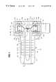
- a rotary blood pump 10includes housing 12 , having an elongated inlet tube 13 with an entry end 13 ′ and an impeller casing or volute 14 .
- a discharge tube 16extends through the housing to communicate with the interior periphery of casing 14 .
- Tube 16has a tangential orientation with respect to the radius of the casing 14 , for effectively channeling the blood output from the pump.
- a pump rotor 17is located within housing 12 and includes a support shaft 18 attached to an impeller 20 . There is a blood flow path 21 between a rotor 17 and the inner sidewalls 23 of inlet tube 13 .
- Rotor 17is mounted for rotation about a longitudinal axis which extends both through shaft 18 and impeller 20 .
- this embodimentincludes an impeller and a casing of centrifugal design, the present invention may also be adapted advantageously to rotary blood pumps of axial flow design or other types of rotary blood pumps.
- Impeller 20has a number of blade sectors that are relatively thick in the axial direction.
- the thick impeller 20has the ability to utilize magnetic pieces 51 and 53 that are inserted in a manner enabling a pair of stators 24 and 26 to be on opposite sides of the impeller.
- a first motor stator 24comprising conductive coils or motor windings 41 a, 44 a, pole pieces 44 , 41 and back iron 31 , is located at the rear of impeller 20 on a wall 24 a.
- a second motor stator 26comprising windings 41 c, 44 c, pole pieces 41 d, 44 d, and back iron 34 , is positioned on the forward side of impeller 20 on a wall 26 a: Although (for simplicity) only two coils and two pole pieces are illustrated on each side of the impeller in FIG. 1, it is to be understood that in the embodiment illustrated in FIGS. 2-9, six windings and pole pieces are on each side of the impeller.
- Magnetic bearings 35are provided on the rotor 17 and magnetic bearings 36 are on the casing 14 for levitating rotor 17 and maintaining it in proper radial alignment with respect to its longitudinal axis.
- a hall sensor 38comprising a magnet 40 along the axis of the impeller 20 and carried by the impeller 20 and a coaxial sensing element 40 a between the impeller and the housing 20 is provided for detecting and measuring axial movement of the impeller.
- the hall sensor 38provides a real time measurement of the axial position of the rotor 17 relative to the stators 24 , 26 and is part of a stator control circuit for varying the current to the motor coils 41 a, 44 a, 41 c, 44 c, in response to measured changes in position of the impeller 20 , in order to apply an axial restoring force to the rotor 17 .
- the impeller 20may carry a magnet along its axis at its distal end and the casing 14 may also have a force transducer responsive to the distance of the magnet for providing a signal reflective of that distance.
- Various position sensorsmay be utilized as desired.
- stator windings 41 a, 44 a, 41 c, 44 care energized to produce equal opposing axial forces on the magnets 51 , 53 .
- windings 44 a and 44 care producing electromagnets which are repelling the adjacent magnet face, i.e., north to north and south to south.
- windings 41 a and 41 care producing electromagnets which are attracting the adjacent magnet faces, i.e., north to south and south to north.
- the net axial force of the stator coils acting on the magnetsis zero, provided that the magnets are axially centered between the stators.
- An imbalance in the current delivered to the coilswill result in an imbalance in the electromagnetic forces produced by the stator coils and, an imbalance in the axial force on the rotor. Torque will not be affected. As discussed below, this imbalanced force is exploited as a restoring force.
- axial restoring forcesare applied to the rotor by controlling the balance of the current in the opposed stator coils.
- the statorsare controlled in parallel so that the current applied to the coils is adjusted to produce the necessary restoring force on the rotor.
- the control of the restoring forceis determined by the position of the rotor assembly as measured by the hall sensor or other type of position sensor.
- the phasing of the restoring force, with respect to the torque angle of the motormay be accomplished in several ways. One way would be to alter only the current balance between the two coils but to keep the phasing of the current the same.
- Another approachwould be to apply a current pulse out of phase with the torque-producing current. In doing this, the restoring current pulse would act when it had the greatest affect on the axial position and the least contribution to torque.
- This strategypreferably utilizes individual control of each coil in order to achieve the desired effect.
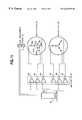
- the motorhas six poles 41 , 42 , 43 , 44 , 45 and 46 in the stator and four poles (magnets) 51 , 52 , 53 and 54 in the rotor, although other combinations of motor poles and stator configurations may be utilized.
- FIGS. 2-6comprise diagrammatic representations of four arc-shaped segments which represent the motor rotor and six arc-shaped segments which represent stator coils or windings.
- the six coils 41 a, 42 a, 43 a, 44 a, 45 a and 46 aare wired in three phases in a wye configuration or a delta configuration, such that, at any moment, two phases (four coils) are energized and the remaining phase (two coils) are not energized.
- coils 43 a and 46 aare phase A coils
- coils 42 a and 45 aare phase B coils
- coils 41 a and 44 aare phase C coils.
- FIGS. 2-6represent only a single stator motor, the principle for the double stator is the same. The stator is illustrated to visualize the resulting electromagnetization produced by the current in the energized coil. Phase A is magnetized to south and phase C to north. Thus there are two north and two south poles. The south poles are 180° apart and the north poles are 180° apart.
- Phase Bis not energized and has no electromagnetic pole. This represents one commutation state of the stator. There are a total of six commutation state combinations for a three phase motor.
- the motor control logicrotates the “wave” of magnetization around the stator in synchrony with the magnets as they spin in order to maintain torque.
- the commutationis done with back emf sensing. The rotor position is found from the back emf signal and the phases are automatically switched to keep positive torque enabling the motor to run continually. Twelve commutations represent a 360° rotation.
- FIGS. 2-6The system for producing an axial restoring force using the stator windings is diagrammatically illustrated in FIGS. 2-6.
- magnet 51is being repelled in the clockwise direction by pole 41 and magnet 54 is being repelled in the counterclockwise direction by pole 46 . Since the magnets are placed symmetrically about the active stator poles, the resulting torque produced in this position is zero.
- magnets 52 and 53with respect to stator poles 43 and 44 . This may be referred to as “unstable” equilibrium point.
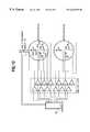
- FIG. 3the rotor has been rotated clockwise 30°. Magnet 54 is now being repelled by pole 46 in the clockwise direction and stator pole 41 is repelling magnet 51 in the clockwise direction, producing clockwise torque. A torque of equal magnitude and in the clockwise direction is also being produced by the action between stator pole 43 and magnet 52 and stator pole 44 and magnet 53 . This is useful torque although it is not maximum torque.
- FIG. 4in which the rotor has been rotated clockwise to 45°.
- Magnet 54is positioned exactly in the middle between stator pole 46 and stator pole 41 .
- Stator pole 46is repelling magnet 54 clockwise and stator pole 41 is attracting magnet 54 clockwise.
- a torque of equal magnitude and in the clockwise directionis also being produced by the action between stator pole 43 and stator pole 44 and magnet 52 .
- Magnets 41 and 43are directly over stator poles 52 and 55 (which do not have excitation current at this time). It should be noted that these diagrams represent only one stator, and that there is a mirror image of this relationship on the other end of the magnets in which all of the magnetic poles are switched to produce synergistic torque.
- FIG. 5the rotor has been rotated clockwise to 60°. Magnet 51 is being attracted by stator pole 43 in the clockwise direction and magnet 52 is being repelled by stator pole 43 in the clockwise direction and attracted by stator pole 44 in the clockwise direction, thereby producing torque that is substantially equal to the torque that is produced at 30°.
- FIG. 6in which the rotor has been rotated clockwise to 90°, magnet 53 is being attracted by stator pole 46 in the clockwise direction and magnet 54 is being attracted to stator pole 41 in the counter clockwise direction.
- the forcesare equal and opposite and no torque is produced.
- magnets 51 and 52 and stator poles 43 and 44respectively. This refers to the “stable” equilibreum point.
- FIG. 7is a side view of the motor unwrapped in the condition discussed above at zero degrees which produces no torque.
- FIG. 8there is a side view of the relationship which exists at 45° with maximum torque.
- FIG. 9is a side view of the rotor at 90° rotation showing the torque to be zero again. If the magnet is precisely in the axial center between the two stator halves, and the current going to both the stators is equal, regardless of the rotational position of the rotor magnets or the sequence of excitation of the stator poles, the combination of magnetic attractive and repulsive forces will cancel each other out in the direction of the z axis, and there will be no net axial force. However, the action between the magnets and stator iron and poles is unstable and non-restoring.
- the graph of FIG. 10illustrates the relationship between the torque angle and the resulting axial force when the current to the stators is 13 AT in one and 39 AT in the other.
- the rotor magnetsare located exactly half way between the two motor stators in the z-axis. This graph shows that a net axial force can be produced.
- the magnitude of the forceis proportional to the difference in current supplied to the upper and lower stator and the rotor angular position. This provides a means of keeping the magnets in the center while still using normal excitation and by manipulating only the current distribution to the two stators.
- a controller 60which may include a microprocessor, operates in response to axial displacement sensor 38 to control the current through amplifier 62 to stator windings 46 a and 43 a; to control the current through amplifier 63 to windings 41 a and 44 a; to control the current through amplifier 64 to windings 42 and 45 of motor stator 24 ; and to control the currents through amplifiers 65 , 66 and 67 to the respective windings of oppositely positioned motor stator 26 .
- the restoring forceis a function of rotor angular position and at the peak torque point, there is little if any available axial force produced by the current imbalance in the stators.
- controller 60controls currents through a number of amplifiers, with each phase of windings having a pair of amplifiers for individual stator pole control.
- FIG. 13A flow diagram illustrating one system for unbalancing the currents to provide a magnetic restoring force is set forth in FIG. 13 .
- zis measured. If z is equal, equal currents are maintained on stator 24 (S 1 ) and stator 26 (S 2 ). However, if z is not zero, then it is determined whether z is greater than zero. If z is greater than zero, then the current to stator 26 (S 2 ) is decreased and the current to stator 24 (S 1 ) is increased. If z is greater than zero, then the current to stator 26 (S 2 ) is increased and the current to stator 24 (S 1 ) is decreased.
- FIG. 13is only one of numerous methods that can be utilized.
Landscapes
- Engineering & Computer Science (AREA)
- Health & Medical Sciences (AREA)
- Heart & Thoracic Surgery (AREA)
- Mechanical Engineering (AREA)
- Cardiology (AREA)
- General Engineering & Computer Science (AREA)
- Life Sciences & Earth Sciences (AREA)
- Veterinary Medicine (AREA)
- Public Health (AREA)
- Anesthesiology (AREA)
- Biomedical Technology (AREA)
- Hematology (AREA)
- General Health & Medical Sciences (AREA)
- Animal Behavior & Ethology (AREA)
- Power Engineering (AREA)
- Electromagnetism (AREA)
- Physics & Mathematics (AREA)
- Control Of Motors That Do Not Use Commutators (AREA)
- External Artificial Organs (AREA)
Abstract
Description
Claims (15)
Priority Applications (10)
| Application Number | Priority Date | Filing Date | Title |
|---|---|---|---|
| US09/204,795US6264635B1 (en) | 1998-12-03 | 1998-12-03 | Active magnetic bearing system for blood pump |
| EP19990957559EP1135181B1 (en) | 1998-12-03 | 1999-11-10 | Centrifugal blood pump comprising an active magnetic bearing system |
| CA 2352270CA2352270A1 (en) | 1998-12-03 | 1999-11-10 | Active magnetic bearing system for blood pump |
| ES99957559TES2279642T3 (en) | 1998-12-03 | 1999-11-10 | CENTRIFUGE PUMP FOR BLOOD THAT INCLUDES A SYSTEM OF ACTIVE MAGNETIC CUSHIONS. |
| PCT/US1999/026839WO2000032257A1 (en) | 1998-12-03 | 1999-11-10 | Active magnetic bearing system for blood pump |
| AU15242/00AAU765716B2 (en) | 1998-12-03 | 1999-11-10 | Active magnetic bearing system for blood pump |
| JP2000584946AJP4146092B2 (en) | 1998-12-03 | 1999-11-10 | Active magnetic bearings for blood pumps |
| IL14336299AIL143362A0 (en) | 1998-12-03 | 1999-11-10 | Active magnetic bearing system for blood pump |
| DE1999634905DE69934905T2 (en) | 1998-12-03 | 1999-11-10 | Centrifugal blood pump with active, magnetic storage system |
| KR1020017006933AKR20010090858A (en) | 1998-12-03 | 1999-11-10 | Active magnetic bearing system for blood pump |
Applications Claiming Priority (1)
| Application Number | Priority Date | Filing Date | Title |
|---|---|---|---|
| US09/204,795US6264635B1 (en) | 1998-12-03 | 1998-12-03 | Active magnetic bearing system for blood pump |
Publications (1)
| Publication Number | Publication Date |
|---|---|
| US6264635B1true US6264635B1 (en) | 2001-07-24 |
Family
ID=22759468
Family Applications (1)
| Application Number | Title | Priority Date | Filing Date |
|---|---|---|---|
| US09/204,795Expired - LifetimeUS6264635B1 (en) | 1998-12-03 | 1998-12-03 | Active magnetic bearing system for blood pump |
Country Status (10)
| Country | Link |
|---|---|
| US (1) | US6264635B1 (en) |
| EP (1) | EP1135181B1 (en) |
| JP (1) | JP4146092B2 (en) |
| KR (1) | KR20010090858A (en) |
| AU (1) | AU765716B2 (en) |
| CA (1) | CA2352270A1 (en) |
| DE (1) | DE69934905T2 (en) |
| ES (1) | ES2279642T3 (en) |
| IL (1) | IL143362A0 (en) |
| WO (1) | WO2000032257A1 (en) |
Cited By (178)
| Publication number | Priority date | Publication date | Assignee | Title |
|---|---|---|---|---|
| US6488484B2 (en)* | 2000-04-07 | 2002-12-03 | Sicce S.P.A. | Hydraulic pump with permanent-magnet motor having a preset direction of rotation |
| US20030001445A1 (en)* | 2001-06-29 | 2003-01-02 | Paden Brad E. | Method and system for positioning a movable body in a magnetic bearing system |
| US6589030B2 (en)* | 2000-06-20 | 2003-07-08 | Ntn Corporation | Magnetically levitated pump apparatus |
| US20030233021A1 (en)* | 2002-06-12 | 2003-12-18 | Miwatec Incorporated | Blood pump |
| US20040033147A1 (en)* | 2001-10-11 | 2004-02-19 | Paul Lum | Micro paddle wheel pump for precise pumping, mixing, dispensing, and valving of blood and reagents |
| US20040047737A1 (en)* | 2002-09-10 | 2004-03-11 | Miwatec Incorporated | Methods and apparatus for controlling a continuous flow rotary blood pump |
| US20040179942A1 (en)* | 2003-03-13 | 2004-09-16 | Tetra Holding (Us), Inc. | Uni-directional impeller, and impeller and rotor assembly |
| US6817836B2 (en)* | 2002-09-10 | 2004-11-16 | Miwatec Incorporated | Methods and apparatus for controlling a continuous flow rotary blood pump |
| US20050084398A1 (en)* | 2003-09-18 | 2005-04-21 | Wampler Richard K. | Rotary blood pump |
| US20050147512A1 (en)* | 2003-10-03 | 2005-07-07 | Foster-Miller, Inc. | Rotary pump with electromagnetic LCR bearing |
| US20050267439A1 (en)* | 2004-05-25 | 2005-12-01 | Sherwood Services, Ag. | Flow control apparatus |
| US20070142696A1 (en)* | 2005-12-08 | 2007-06-21 | Ventrassist Pty Ltd | Implantable medical devices |
| US20070161847A1 (en)* | 2001-05-21 | 2007-07-12 | Woodard John C | Staged implantation of ventricular assist devices |
| US20070276480A1 (en)* | 2003-10-09 | 2007-11-29 | Tansley Geoffrey D | Impeller |
| US20080200750A1 (en)* | 2006-11-17 | 2008-08-21 | Natalie James | Polymer encapsulation for medical device |
| US20090155049A1 (en)* | 1997-09-05 | 2009-06-18 | Ventrassist Pty Ltd. | Rotary pump with exclusively hydrodynamically suspended impeller |
| US20090306492A1 (en)* | 2005-07-12 | 2009-12-10 | Nicholas Andrew Earl | Restraining device for a percutaneous lead assembly |
| US20100036487A1 (en)* | 2006-10-27 | 2010-02-11 | Ventrassist Pty. Ltd. | Blood Pump With An Ultrasound Transducer |
| US20100106225A1 (en)* | 2003-08-01 | 2010-04-29 | Ventracor Limited | Transcutaneous Power And/Or Data Transceiver |
| US20100185280A1 (en)* | 1999-04-23 | 2010-07-22 | Ventrassist Pty. Ltd | Rotary blood pump and control system therefor |
| US7875047B2 (en) | 2002-04-19 | 2011-01-25 | Pelikan Technologies, Inc. | Method and apparatus for a multi-use body fluid sampling device with sterility barrier release |
| CN101417155B (en)* | 2008-11-22 | 2011-02-09 | 燕山大学 | Magnetic levitation implantable conical helical impeller rotor blood pump driven by external magnetic field |
| US7892183B2 (en) | 2002-04-19 | 2011-02-22 | Pelikan Technologies, Inc. | Method and apparatus for body fluid sampling and analyte sensing |
| US7901365B2 (en) | 2002-04-19 | 2011-03-08 | Pelikan Technologies, Inc. | Method and apparatus for penetrating tissue |
| US7909778B2 (en) | 2002-04-19 | 2011-03-22 | Pelikan Technologies, Inc. | Method and apparatus for penetrating tissue |
| US7909777B2 (en) | 2002-04-19 | 2011-03-22 | Pelikan Technologies, Inc | Method and apparatus for penetrating tissue |
| US7909774B2 (en) | 2002-04-19 | 2011-03-22 | Pelikan Technologies, Inc. | Method and apparatus for penetrating tissue |
| US7909775B2 (en) | 2001-06-12 | 2011-03-22 | Pelikan Technologies, Inc. | Method and apparatus for lancet launching device integrated onto a blood-sampling cartridge |
| US7914465B2 (en) | 2002-04-19 | 2011-03-29 | Pelikan Technologies, Inc. | Method and apparatus for penetrating tissue |
| US7976476B2 (en) | 2002-04-19 | 2011-07-12 | Pelikan Technologies, Inc. | Device and method for variable speed lancet |
| US7981055B2 (en) | 2001-06-12 | 2011-07-19 | Pelikan Technologies, Inc. | Tissue penetration device |
| US7981056B2 (en) | 2002-04-19 | 2011-07-19 | Pelikan Technologies, Inc. | Methods and apparatus for lancet actuation |
| US20110178361A1 (en)* | 2010-01-19 | 2011-07-21 | Barry Yomtov | Physiologically responsive vad |
| US7988645B2 (en) | 2001-06-12 | 2011-08-02 | Pelikan Technologies, Inc. | Self optimizing lancing device with adaptation means to temporal variations in cutaneous properties |
| US8007446B2 (en) | 2002-04-19 | 2011-08-30 | Pelikan Technologies, Inc. | Method and apparatus for penetrating tissue |
| US8062231B2 (en) | 2002-04-19 | 2011-11-22 | Pelikan Technologies, Inc. | Method and apparatus for penetrating tissue |
| US8079960B2 (en) | 2002-04-19 | 2011-12-20 | Pelikan Technologies, Inc. | Methods and apparatus for lancet actuation |
| US8197421B2 (en) | 2002-04-19 | 2012-06-12 | Pelikan Technologies, Inc. | Method and apparatus for penetrating tissue |
| US20120169167A1 (en)* | 2010-12-30 | 2012-07-05 | Chung Yuan Christian University | Axial Hybrid Magnetic Bearing, Method for Operation thereof, and Structure for Rotor thereof |
| US8221334B2 (en) | 2002-04-19 | 2012-07-17 | Sanofi-Aventis Deutschland Gmbh | Method and apparatus for penetrating tissue |
| US8251921B2 (en) | 2003-06-06 | 2012-08-28 | Sanofi-Aventis Deutschland Gmbh | Method and apparatus for body fluid sampling and analyte sensing |
| US8262614B2 (en) | 2003-05-30 | 2012-09-11 | Pelikan Technologies, Inc. | Method and apparatus for fluid injection |
| US8267870B2 (en) | 2002-04-19 | 2012-09-18 | Sanofi-Aventis Deutschland Gmbh | Method and apparatus for body fluid sampling with hybrid actuation |
| US8282576B2 (en) | 2003-09-29 | 2012-10-09 | Sanofi-Aventis Deutschland Gmbh | Method and apparatus for an improved sample capture device |
| US8296918B2 (en) | 2003-12-31 | 2012-10-30 | Sanofi-Aventis Deutschland Gmbh | Method of manufacturing a fluid sampling device with improved analyte detecting member configuration |
| US20120310139A1 (en)* | 2009-11-09 | 2012-12-06 | Medtronic Xomed, Inc. | Adjustable valve setting with motor control |
| US8333710B2 (en) | 2002-04-19 | 2012-12-18 | Sanofi-Aventis Deutschland Gmbh | Tissue penetration device |
| US8353686B2 (en) | 2004-10-18 | 2013-01-15 | Thoratec Corporation | Rotor stability of a rotary pump |
| US8360992B2 (en) | 2002-04-19 | 2013-01-29 | Sanofi-Aventis Deutschland Gmbh | Method and apparatus for penetrating tissue |
| US8372016B2 (en) | 2002-04-19 | 2013-02-12 | Sanofi-Aventis Deutschland Gmbh | Method and apparatus for body fluid sampling and analyte sensing |
| US8382682B2 (en) | 2002-04-19 | 2013-02-26 | Sanofi-Aventis Deutschland Gmbh | Method and apparatus for penetrating tissue |
| US8435190B2 (en) | 2002-04-19 | 2013-05-07 | Sanofi-Aventis Deutschland Gmbh | Method and apparatus for penetrating tissue |
| US8439872B2 (en) | 1998-03-30 | 2013-05-14 | Sanofi-Aventis Deutschland Gmbh | Apparatus and method for penetration with shaft having a sensor for sensing penetration depth |
| US8556829B2 (en) | 2002-04-19 | 2013-10-15 | Sanofi-Aventis Deutschland Gmbh | Method and apparatus for penetrating tissue |
| US8562509B2 (en) | 2010-12-30 | 2013-10-22 | Cook Medical Technologies Llc | Ventricular assist device |
| US8574895B2 (en) | 2002-12-30 | 2013-11-05 | Sanofi-Aventis Deutschland Gmbh | Method and apparatus using optical techniques to measure analyte levels |
| WO2013173751A1 (en)* | 2012-05-17 | 2013-11-21 | Heartware, Inc. | Magnetically suspended pump |
| US8641644B2 (en) | 2000-11-21 | 2014-02-04 | Sanofi-Aventis Deutschland Gmbh | Blood testing apparatus having a rotatable cartridge with multiple lancing elements and testing means |
| US8652831B2 (en) | 2004-12-30 | 2014-02-18 | Sanofi-Aventis Deutschland Gmbh | Method and apparatus for analyte measurement test time |
| US8668656B2 (en) | 2003-12-31 | 2014-03-11 | Sanofi-Aventis Deutschland Gmbh | Method and apparatus for improving fluidic flow and sample capture |
| US8702624B2 (en) | 2006-09-29 | 2014-04-22 | Sanofi-Aventis Deutschland Gmbh | Analyte measurement device with a single shot actuator |
| US8721671B2 (en) | 2001-06-12 | 2014-05-13 | Sanofi-Aventis Deutschland Gmbh | Electric lancet actuator |
| US8770945B2 (en) | 2009-03-06 | 2014-07-08 | Thoratec Corporation | Centrifugal pump apparatus |
| US8784335B2 (en) | 2002-04-19 | 2014-07-22 | Sanofi-Aventis Deutschland Gmbh | Body fluid sampling device with a capacitive sensor |
| US8821365B2 (en) | 2009-07-29 | 2014-09-02 | Thoratec Corporation | Rotation drive device and centrifugal pump apparatus using the same |
| US8827661B2 (en) | 2008-06-23 | 2014-09-09 | Thoratec Corporation | Blood pump apparatus |
| US8828203B2 (en) | 2004-05-20 | 2014-09-09 | Sanofi-Aventis Deutschland Gmbh | Printable hydrogels for biosensors |
| US20140271280A1 (en)* | 2013-03-15 | 2014-09-18 | Merkle-Korff Industries, Inc. | Pump motor |
| US8905910B2 (en) | 2010-06-22 | 2014-12-09 | Thoratec Corporation | Fluid delivery system and method for monitoring fluid delivery system |
| US8965476B2 (en) | 2010-04-16 | 2015-02-24 | Sanofi-Aventis Deutschland Gmbh | Tissue penetration device |
| US9067005B2 (en) | 2008-12-08 | 2015-06-30 | Thoratec Corporation | Centrifugal pump apparatus |
| US9068572B2 (en) | 2010-07-12 | 2015-06-30 | Thoratec Corporation | Centrifugal pump apparatus |
| US9089635B2 (en) | 2010-06-22 | 2015-07-28 | Thoratec Corporation | Apparatus and method for modifying pressure-flow characteristics of a pump |
| US9132215B2 (en) | 2010-02-16 | 2015-09-15 | Thoratee Corporation | Centrifugal pump apparatus |
| US9133854B2 (en) | 2010-03-26 | 2015-09-15 | Thoratec Corporation | Centrifugal blood pump device |
| US9144401B2 (en) | 2003-06-11 | 2015-09-29 | Sanofi-Aventis Deutschland Gmbh | Low pain penetrating member |
| US9226699B2 (en) | 2002-04-19 | 2016-01-05 | Sanofi-Aventis Deutschland Gmbh | Body fluid sampling module with a continuous compression tissue interface surface |
| US9248267B2 (en) | 2002-04-19 | 2016-02-02 | Sanofi-Aventis Deustchland Gmbh | Tissue penetration device |
| US9314194B2 (en) | 2002-04-19 | 2016-04-19 | Sanofi-Aventis Deutschland Gmbh | Tissue penetration device |
| US9351680B2 (en) | 2003-10-14 | 2016-05-31 | Sanofi-Aventis Deutschland Gmbh | Method and apparatus for a variable user interface |
| US9366261B2 (en) | 2012-01-18 | 2016-06-14 | Thoratec Corporation | Centrifugal pump device |
| US9371826B2 (en) | 2013-01-24 | 2016-06-21 | Thoratec Corporation | Impeller position compensation using field oriented control |
| US9375169B2 (en) | 2009-01-30 | 2016-06-28 | Sanofi-Aventis Deutschland Gmbh | Cam drive for managing disposable penetrating member actions with a single motor and motor and control system |
| US9381285B2 (en) | 2009-03-05 | 2016-07-05 | Thoratec Corporation | Centrifugal pump apparatus |
| US9382908B2 (en) | 2010-09-14 | 2016-07-05 | Thoratec Corporation | Centrifugal pump apparatus |
| US9386944B2 (en) | 2008-04-11 | 2016-07-12 | Sanofi-Aventis Deutschland Gmbh | Method and apparatus for analyte detecting device |
| US20160235899A1 (en)* | 2015-02-12 | 2016-08-18 | Thoratec Corporation | System and method for controlling the position of a levitated rotor |
| US9427532B2 (en) | 2001-06-12 | 2016-08-30 | Sanofi-Aventis Deutschland Gmbh | Tissue penetration device |
| US9433714B2 (en) | 2012-06-06 | 2016-09-06 | Heartware, Inc. | Speed change algorithm for a continuous flow blood pump |
| US9433717B2 (en) | 2010-09-24 | 2016-09-06 | Thoratec Corporation | Generating artificial pulse |
| US9492599B2 (en) | 2012-08-31 | 2016-11-15 | Thoratec Corporation | Hall sensor mounting in an implantable blood pump |
| US9512852B2 (en) | 2006-03-31 | 2016-12-06 | Thoratec Corporation | Rotary blood pump |
| US9526818B2 (en) | 2014-04-15 | 2016-12-27 | Thoratec Corporation | Protective cap for driveline cable connector |
| WO2017015210A1 (en) | 2015-07-20 | 2017-01-26 | Thoratec Corporation | Strain gauge for flow estimation |
| WO2017015268A1 (en) | 2015-07-20 | 2017-01-26 | Thoratec Corporation | Flow estimation using hall-effect sensors |
| US9556873B2 (en) | 2013-02-27 | 2017-01-31 | Tc1 Llc | Startup sequence for centrifugal pump with levitated impeller |
| US9603984B2 (en) | 2014-09-03 | 2017-03-28 | Tci Llc | Triple helix driveline cable and methods of assembly and use |
| WO2017053767A1 (en) | 2015-09-25 | 2017-03-30 | Heartware, Inc. | Blood pump for ischemia detection and treatment |
| US9623161B2 (en) | 2014-08-26 | 2017-04-18 | Tc1 Llc | Blood pump and method of suction detection |
| US9629948B2 (en) | 2014-04-15 | 2017-04-25 | Tc1 Llc | Methods for upgrading ventricle assist devices |
| WO2017070331A1 (en) | 2015-10-23 | 2017-04-27 | Heartware, Inc. | Physiologically responsive blood pump for ischemia detection and treatment |
| US9656010B2 (en) | 2010-07-22 | 2017-05-23 | Tc1 Llc | Controlling implanted blood pumps |
| WO2017087380A1 (en) | 2015-11-20 | 2017-05-26 | Tc1 Llc | System architecture that allows patient replacement of vad controller/interface module without disconnection of old module |
| WO2017087785A1 (en) | 2015-11-20 | 2017-05-26 | Tc1 Llc | Energy management of blood pump controllers |
| WO2017087717A1 (en) | 2015-11-20 | 2017-05-26 | Tc1 Llc | Blood pump controllers having daisy-chained batteries |
| WO2017087728A1 (en) | 2015-11-20 | 2017-05-26 | Tc1 Llc | Improved connectors and cables for use with ventricle assist systems |
| US9675741B2 (en) | 2010-08-20 | 2017-06-13 | Tc1 Llc | Implantable blood pump |
| US9694123B2 (en) | 2014-04-15 | 2017-07-04 | Tc1 Llc | Methods and systems for controlling a blood pump |
| US9713663B2 (en) | 2013-04-30 | 2017-07-25 | Tc1 Llc | Cardiac pump with speed adapted for ventricle unloading |
| US9731058B2 (en) | 2012-08-31 | 2017-08-15 | Tc1 Llc | Start-up algorithm for an implantable blood pump |
| US9744280B2 (en) | 2014-04-15 | 2017-08-29 | Tc1 Llc | Methods for LVAD operation during communication losses |
| US9775553B2 (en) | 2004-06-03 | 2017-10-03 | Sanofi-Aventis Deutschland Gmbh | Method and apparatus for a fluid sampling device |
| US9782527B2 (en) | 2009-05-27 | 2017-10-10 | Tc1 Llc | Monitoring of redundant conductors |
| US9786150B2 (en) | 2014-04-15 | 2017-10-10 | Tci Llc | Methods and systems for providing battery feedback to patient |
| US9795747B2 (en) | 2010-06-02 | 2017-10-24 | Sanofi-Aventis Deutschland Gmbh | Methods and apparatus for lancet actuation |
| US9820684B2 (en) | 2004-06-03 | 2017-11-21 | Sanofi-Aventis Deutschland Gmbh | Method and apparatus for a fluid sampling device |
| US9850906B2 (en) | 2011-03-28 | 2017-12-26 | Tc1 Llc | Rotation drive device and centrifugal pump apparatus employing same |
| US9849224B2 (en) | 2014-04-15 | 2017-12-26 | Tc1 Llc | Ventricular assist devices |
| WO2018005228A1 (en) | 2016-07-01 | 2018-01-04 | Heartware, Inc. | Systems and methods for maintaining fluid balance |
| US9872976B2 (en) | 2010-08-20 | 2018-01-23 | Thoratec Corporation | Assembly and method for stabilizing a percutaneous cable |
| US20180051699A1 (en)* | 2010-09-01 | 2018-02-22 | Levitronix Gmbh | Rotary pump |
| WO2018057795A1 (en) | 2016-09-26 | 2018-03-29 | Tc1 Llc | Heart pump driveline power modulation |
| WO2018057509A1 (en) | 2016-09-23 | 2018-03-29 | Heartware, Inc. | Physiologically responsive vad for cardiac events |
| US9985374B2 (en) | 2016-05-06 | 2018-05-29 | Tc1 Llc | Compliant implantable connector and methods of use and manufacture |
| WO2018102360A1 (en) | 2016-11-30 | 2018-06-07 | Heartware, Inc. | Patient behavior sensitive controller |
| US10029039B2 (en) | 2009-12-30 | 2018-07-24 | Tc1 Llc | Mobility-enhancing blood pump system |
| US10029038B2 (en) | 2015-07-21 | 2018-07-24 | Tc1 Llc | Cantilevered rotor pump and methods for axial flow blood pumping |
| WO2018136592A2 (en) | 2017-01-18 | 2018-07-26 | Tc1 Llc | Systems and methods for transcutaneous power transfer using microneedles |
| US10052420B2 (en) | 2013-04-30 | 2018-08-21 | Tc1 Llc | Heart beat identification and pump speed synchronization |
| WO2018195301A1 (en) | 2017-04-21 | 2018-10-25 | Tc1 Llc | Aortic connectors and methods of use |
| WO2018201134A1 (en) | 2017-04-28 | 2018-11-01 | Tc1 Llc | Patient adapter for driveline cable and methods |
| US10243434B2 (en) | 2014-06-30 | 2019-03-26 | Nidec Motor Corporation | Stator with overmolded core and mold for producing same |
| US10245361B2 (en) | 2015-02-13 | 2019-04-02 | Tc1 Llc | Impeller suspension mechanism for heart pump |
| US20190167874A1 (en)* | 2017-12-05 | 2019-06-06 | Heartware, Inc. | Blood pump with impeller rinse operation |
| WO2019135876A1 (en) | 2018-01-02 | 2019-07-11 | Tc1 Llc | Fluid treatment system for a driveline and methods of assembly and use |
| WO2019139686A1 (en) | 2018-01-10 | 2019-07-18 | Tc1 Llc | Bearingless implantable blood pump |
| US10371152B2 (en) | 2015-02-12 | 2019-08-06 | Tc1 Llc | Alternating pump gaps |
| WO2019183126A1 (en) | 2018-03-20 | 2019-09-26 | Tc1 Llc | Mechanical gauge for estimating inductance changes in resonant power transfer systems with flexible coils for use with implanted medical devices |
| WO2019190998A1 (en) | 2018-03-26 | 2019-10-03 | Tc1 Llc | Methods and systems for irrigating and capturing particulates during heart pump implantation |
| US10441693B2 (en) | 2016-04-01 | 2019-10-15 | Heartware, Inc. | Axial flow blood pump with radially offset rotor |
| WO2019212861A1 (en) | 2018-04-30 | 2019-11-07 | Tc1 Llc | Improved blood pump connectors |
| WO2019232080A1 (en) | 2018-05-31 | 2019-12-05 | Tc1 Llc | Improved blood pump controllers |
| US10506935B2 (en) | 2015-02-11 | 2019-12-17 | Tc1 Llc | Heart beat identification and pump speed synchronization |
| EP3597231A1 (en) | 2018-07-17 | 2020-01-22 | Tc1 Llc | Systems and methods for inertial sensing for vad diagnostics and closed loop control |
| US10543301B2 (en) | 2016-01-06 | 2020-01-28 | Bivacor Inc. | Heart pump |
| US10589013B2 (en) | 2016-08-26 | 2020-03-17 | Tci Llc | Prosthetic rib with integrated percutaneous connector for ventricular assist devices |
| WO2020068333A1 (en) | 2018-09-25 | 2020-04-02 | Tc1 Llc | Adaptive speed control algorithms and controllers for optimizing flow in ventricular assist devices |
| US10660997B2 (en)* | 2016-09-23 | 2020-05-26 | Heartware, Inc. | Blood pump with sensors on housing surface |
| US10660998B2 (en) | 2016-08-12 | 2020-05-26 | Tci Llc | Devices and methods for monitoring bearing and seal performance |
| US10665080B2 (en) | 2016-10-20 | 2020-05-26 | Tc1 Llc | Methods and systems for bone conduction audible alarms for mechanical circulatory support systems |
| US10701043B2 (en) | 2018-01-17 | 2020-06-30 | Tc1 Llc | Methods for physical authentication of medical devices during wireless pairing |
| US10702641B2 (en) | 2015-06-29 | 2020-07-07 | Tc1 Llc | Ventricular assist devices having a hollow rotor and methods of use |
| CN111375098A (en)* | 2018-12-29 | 2020-07-07 | 上海微创心力医疗科技有限公司 | Percutaneous blood pump and rotor limit structure thereof |
| US10722632B2 (en) | 2015-08-28 | 2020-07-28 | Tc1 Llc | Blood pump controllers and methods of use for improved energy efficiency |
| US10780207B2 (en) | 2015-05-15 | 2020-09-22 | Tc1 Llc | Axial flow blood pump |
| US10792407B2 (en) | 2017-01-12 | 2020-10-06 | Tc1 Llc | Percutaneous driveline anchor devices and methods of use |
| US10857273B2 (en) | 2016-07-21 | 2020-12-08 | Tc1 Llc | Rotary seal for cantilevered rotor pump and methods for axial flow blood pumping |
| US10888645B2 (en) | 2015-11-16 | 2021-01-12 | Tc1 Llc | Pressure/flow characteristic modification of a centrifugal pump in a ventricular assist device |
| CN112206409A (en)* | 2020-11-10 | 2021-01-12 | 山东大学 | A magnetic levitation mixed-flow heart pump |
| US10894114B2 (en) | 2017-01-12 | 2021-01-19 | Tc1 Llc | Driveline bone anchors and methods of use |
| US10953145B2 (en) | 2018-03-21 | 2021-03-23 | Tci Llc | Driveline connectors and methods for use with heart pump controllers |
| US11389641B2 (en) | 2018-03-21 | 2022-07-19 | Tc1 Llc | Modular flying lead cable and methods for use with heart pump controllers |
| EP4075609A1 (en) | 2021-04-15 | 2022-10-19 | Tc1 Llc | Systems and methods for medical device connectors |
| CN115282466A (en)* | 2022-06-30 | 2022-11-04 | 上海东心生物医疗科技有限公司 | Full magnetic suspension centrifugal blood pump |
| US11529508B2 (en) | 2018-03-02 | 2022-12-20 | Tc1 Llc | Wearable accessory for ventricular assist system |
| CN115940746A (en)* | 2023-02-16 | 2023-04-07 | 深圳核心医疗科技有限公司 | Motor axial force control method and device |
| US11654274B2 (en) | 2017-04-05 | 2023-05-23 | Bivacor Inc. | Heart pump drive and bearing |
| CN116241486A (en)* | 2023-02-23 | 2023-06-09 | 泰格运控(江苏)技术有限公司 | Flat natural magnetic suspension high-speed compressor |
| WO2023158493A1 (en) | 2022-02-16 | 2023-08-24 | Tc1 Llc | Real time heart rate monitoring for close loop control and/or artificial pulse synchronization of implantable ventricular assist devices |
| WO2023229899A1 (en) | 2022-05-26 | 2023-11-30 | Tc1 Llc | Tri-axis accelerometers for patient physiologic monitoring and closed loop control of implantable ventricular assist devices |
| WO2023235230A1 (en) | 2022-06-02 | 2023-12-07 | Tc1 Llc | Implanted connector booster sealing for implantable medical devices |
| WO2024050319A1 (en) | 2022-08-29 | 2024-03-07 | Tc1 Llc | Implantable electrical connector assembly |
| WO2024097236A1 (en) | 2022-11-01 | 2024-05-10 | Tc1 Llc | Assessment and management of adverse event risks in mechanical circulatory support patients |
| US12029890B2 (en) | 2020-01-21 | 2024-07-09 | Boston Scientific Scimed, Inc. | Magnetic drives having flux enhancers for blood pumps |
| US12133976B2 (en) | 2021-11-23 | 2024-11-05 | Boston Scientific Scimed, Inc. | Percutaneous circulatory support device facilitating reduced hemolysis class |
| WO2025039550A1 (en)* | 2023-08-21 | 2025-02-27 | 上海东心生物医疗科技有限公司 | Hybrid magnetic suspension centrifugal blood pump |
| WO2025137296A1 (en) | 2023-12-22 | 2025-06-26 | Tc1 Llc | Utilization of a left-ventricular pressure sensor for measurement of left-atrial and aortic pressure |
| US12440239B2 (en) | 2021-06-24 | 2025-10-14 | Tc1 Llc | Methods and systems for irrigating particulates during heart pump implantation |
Families Citing this family (8)
| Publication number | Priority date | Publication date | Assignee | Title |
|---|---|---|---|---|
| DE10330434A1 (en) | 2003-07-04 | 2005-02-03 | Jostra Ag | Centrifugal pump |
| DE102007036692A1 (en) | 2006-09-22 | 2008-03-27 | Ebm-Papst St. Georgen Gmbh & Co. Kg | Fan |
| WO2010118476A1 (en) | 2009-04-16 | 2010-10-21 | Bivacor Pty Ltd | Heart pump controller |
| JP5893394B2 (en)* | 2011-12-27 | 2016-03-23 | 川崎重工業株式会社 | Permanent magnet synchronous machine, driving apparatus and driving method for permanent magnet synchronous machine |
| DE102012201252A1 (en)* | 2012-01-30 | 2013-08-01 | Siemens Aktiengesellschaft | Longitudinal bearing disk for a turbomachine rotor |
| EP3173109A1 (en)* | 2015-11-30 | 2017-05-31 | Fundacja Rozwoju Kardiochirurgii Im. Prof. Zbigniewa Religi | Method for controlling a centrifugal heart assist pomp impeller position |
| US11632015B2 (en) | 2018-08-28 | 2023-04-18 | Boston Scientific Scimed, Inc. | Axial flux motor for percutaneous circulatory support device |
| EP3659640A1 (en)* | 2018-11-27 | 2020-06-03 | Berlin Heart GmbH | Method for production of a bearing assembly for an implantable blood pump, bearing assembly and implantable blood pump |
Citations (16)
| Publication number | Priority date | Publication date | Assignee | Title |
|---|---|---|---|---|
| US3572982A (en) | 1968-03-02 | 1971-03-30 | Siemens Ag | Pump with gap-tube motor |
| WO1988007842A1 (en)* | 1987-04-09 | 1988-10-20 | Nimbus Medical, Inc. | Magnetically suspended rotor axial flow blood pump |
| US4876492A (en) | 1988-02-26 | 1989-10-24 | General Electric Company | Electronically commutated motor driven apparatus including an impeller in a housing driven by a stator on the housing |
| US4880362A (en) | 1988-05-24 | 1989-11-14 | Laing Karsten A | Rotor with stabilizing magnets |
| DE4102707A1 (en) | 1990-01-31 | 1991-08-08 | Ntn Toyo Bearing Co Ltd | TURBO PUMP WITH MAGNETICALLY BEARED WING WHEEL |
| US5049134A (en) | 1989-05-08 | 1991-09-17 | The Cleveland Clinic Foundation | Sealless heart pump |
| US5197865A (en) | 1990-10-16 | 1993-03-30 | Micropump Corporation | Integral electronically commutated drive system |
| US5350283A (en) | 1991-12-04 | 1994-09-27 | Ntn Corporation | Clean pump |
| US5591017A (en) | 1994-10-03 | 1997-01-07 | Ametek, Inc. | Motorized impeller assembly |
| US5692882A (en) | 1993-11-10 | 1997-12-02 | The United States Of America As Represented By The Administrator Of The National Aeronautics And Space Administration | Axial pump |
| US5695471A (en) | 1996-02-20 | 1997-12-09 | Kriton Medical, Inc. | Sealless rotary blood pump with passive magnetic radial bearings and blood immersed axial bearings |
| US5725357A (en) | 1995-04-03 | 1998-03-10 | Ntn Corporation | Magnetically suspended type pump |
| US5728154A (en) | 1996-02-29 | 1998-03-17 | Minnesota Mining And Manfacturing Company | Communication method for implantable medical device |
| WO1998011650A1 (en) | 1996-09-10 | 1998-03-19 | Sulzer Electronics Ag | Rotary pump and process to operate it |
| US5738503A (en) | 1995-01-24 | 1998-04-14 | Robert Bosch Gmbh | Method for balancing an electrically driven air blower unit |
| US5840070A (en) | 1996-02-20 | 1998-11-24 | Kriton Medical, Inc. | Sealless rotary blood pump |
- 1998
- 1998-12-03USUS09/204,795patent/US6264635B1/ennot_activeExpired - Lifetime
- 1999
- 1999-11-10EPEP19990957559patent/EP1135181B1/ennot_activeExpired - Lifetime
- 1999-11-10KRKR1020017006933Apatent/KR20010090858A/ennot_activeWithdrawn
- 1999-11-10WOPCT/US1999/026839patent/WO2000032257A1/enactiveIP Right Grant
- 1999-11-10ILIL14336299Apatent/IL143362A0/enunknown
- 1999-11-10JPJP2000584946Apatent/JP4146092B2/ennot_activeExpired - Lifetime
- 1999-11-10DEDE1999634905patent/DE69934905T2/ennot_activeExpired - Lifetime
- 1999-11-10AUAU15242/00Apatent/AU765716B2/ennot_activeExpired
- 1999-11-10ESES99957559Tpatent/ES2279642T3/ennot_activeExpired - Lifetime
- 1999-11-10CACA 2352270patent/CA2352270A1/ennot_activeAbandoned
Patent Citations (16)
| Publication number | Priority date | Publication date | Assignee | Title |
|---|---|---|---|---|
| US3572982A (en) | 1968-03-02 | 1971-03-30 | Siemens Ag | Pump with gap-tube motor |
| WO1988007842A1 (en)* | 1987-04-09 | 1988-10-20 | Nimbus Medical, Inc. | Magnetically suspended rotor axial flow blood pump |
| US4876492A (en) | 1988-02-26 | 1989-10-24 | General Electric Company | Electronically commutated motor driven apparatus including an impeller in a housing driven by a stator on the housing |
| US4880362A (en) | 1988-05-24 | 1989-11-14 | Laing Karsten A | Rotor with stabilizing magnets |
| US5049134A (en) | 1989-05-08 | 1991-09-17 | The Cleveland Clinic Foundation | Sealless heart pump |
| DE4102707A1 (en) | 1990-01-31 | 1991-08-08 | Ntn Toyo Bearing Co Ltd | TURBO PUMP WITH MAGNETICALLY BEARED WING WHEEL |
| US5197865A (en) | 1990-10-16 | 1993-03-30 | Micropump Corporation | Integral electronically commutated drive system |
| US5350283A (en) | 1991-12-04 | 1994-09-27 | Ntn Corporation | Clean pump |
| US5692882A (en) | 1993-11-10 | 1997-12-02 | The United States Of America As Represented By The Administrator Of The National Aeronautics And Space Administration | Axial pump |
| US5591017A (en) | 1994-10-03 | 1997-01-07 | Ametek, Inc. | Motorized impeller assembly |
| US5738503A (en) | 1995-01-24 | 1998-04-14 | Robert Bosch Gmbh | Method for balancing an electrically driven air blower unit |
| US5725357A (en) | 1995-04-03 | 1998-03-10 | Ntn Corporation | Magnetically suspended type pump |
| US5695471A (en) | 1996-02-20 | 1997-12-09 | Kriton Medical, Inc. | Sealless rotary blood pump with passive magnetic radial bearings and blood immersed axial bearings |
| US5840070A (en) | 1996-02-20 | 1998-11-24 | Kriton Medical, Inc. | Sealless rotary blood pump |
| US5728154A (en) | 1996-02-29 | 1998-03-17 | Minnesota Mining And Manfacturing Company | Communication method for implantable medical device |
| WO1998011650A1 (en) | 1996-09-10 | 1998-03-19 | Sulzer Electronics Ag | Rotary pump and process to operate it |
Non-Patent Citations (5)
| Title |
|---|
| C. Peter Cho et al.; Cogging Torque Reduction, Axial Force Variation, and Output Torque Effect of a High-Power-Density, Axial Field, Brushless, Permanent Magnet Motor; Jun. 6, 1995; Proceedings, Twenty-fourth Annual Symposium, Incremental Motion Control Systems & Devices, pp. 297-307. |
| C. Peter Cho et al.; Eddy Current Loss Calculation in the Permanent Magnet of a Large Horse Power Axial-Field Motor; Jun. 14, 1994; Proceedings, Twenty-third Annual Symposium, Incremental Motion Control Systems & Devices, pp. 245-253. |
| C. Peter Cho et al.; Energy Losses in Magnetic Lamination Materials of a Novel Integrated Motor/Pump System; Jul. 22, 1997; Proceedings, Twenty-sixth Annaul Symposium, Incremental Motion Control Systems & Devices, pp. 325-333. |
| C. Peter Cho et al.; Feasibiltiy Study of a Novel Integrated Electric Motor/Pump for Underwater Applications; Jun. 6, 1995; Proceedings, Twenty-sixth Annual Symposium, Incremental Motion Control Systems & Devices, pp. 309-316. |
| C. Peter Cho et al.; Ongoing Feasibility Study of a Novel Integrated Electric Motor/Pump Concept; Jun. 11, 1996; Proceedings, Twenty-fifth Annual Symposium, Incremental Motion Control Systems & Devices, pp. 51-62. |
Cited By (387)
| Publication number | Priority date | Publication date | Assignee | Title |
|---|---|---|---|---|
| US8002518B2 (en) | 1997-09-05 | 2011-08-23 | Thoratec Corporation | Rotary pump with hydrodynamically suspended impeller |
| US20090155049A1 (en)* | 1997-09-05 | 2009-06-18 | Ventrassist Pty Ltd. | Rotary pump with exclusively hydrodynamically suspended impeller |
| US8439872B2 (en) | 1998-03-30 | 2013-05-14 | Sanofi-Aventis Deutschland Gmbh | Apparatus and method for penetration with shaft having a sensor for sensing penetration depth |
| US8870552B2 (en) | 1999-04-23 | 2014-10-28 | Thoratec Corporation | Rotary blood pump and control system therefor |
| US20100185280A1 (en)* | 1999-04-23 | 2010-07-22 | Ventrassist Pty. Ltd | Rotary blood pump and control system therefor |
| US8282359B2 (en) | 1999-04-23 | 2012-10-09 | Thoratec Corporation | Rotary blood pump and control system therefor |
| US6488484B2 (en)* | 2000-04-07 | 2002-12-03 | Sicce S.P.A. | Hydraulic pump with permanent-magnet motor having a preset direction of rotation |
| US6589030B2 (en)* | 2000-06-20 | 2003-07-08 | Ntn Corporation | Magnetically levitated pump apparatus |
| US8641644B2 (en) | 2000-11-21 | 2014-02-04 | Sanofi-Aventis Deutschland Gmbh | Blood testing apparatus having a rotatable cartridge with multiple lancing elements and testing means |
| US20070161847A1 (en)* | 2001-05-21 | 2007-07-12 | Woodard John C | Staged implantation of ventricular assist devices |
| US8388649B2 (en) | 2001-05-21 | 2013-03-05 | Thoratec Corporation | Staged implantation of ventricular assist devices |
| US8282577B2 (en) | 2001-06-12 | 2012-10-09 | Sanofi-Aventis Deutschland Gmbh | Method and apparatus for lancet launching device integrated onto a blood-sampling cartridge |
| US8211037B2 (en) | 2001-06-12 | 2012-07-03 | Pelikan Technologies, Inc. | Tissue penetration device |
| US8343075B2 (en) | 2001-06-12 | 2013-01-01 | Sanofi-Aventis Deutschland Gmbh | Tissue penetration device |
| US9802007B2 (en) | 2001-06-12 | 2017-10-31 | Sanofi-Aventis Deutschland Gmbh | Methods and apparatus for lancet actuation |
| US7981055B2 (en) | 2001-06-12 | 2011-07-19 | Pelikan Technologies, Inc. | Tissue penetration device |
| US8337421B2 (en) | 2001-06-12 | 2012-12-25 | Sanofi-Aventis Deutschland Gmbh | Tissue penetration device |
| US8721671B2 (en) | 2001-06-12 | 2014-05-13 | Sanofi-Aventis Deutschland Gmbh | Electric lancet actuator |
| US8679033B2 (en) | 2001-06-12 | 2014-03-25 | Sanofi-Aventis Deutschland Gmbh | Tissue penetration device |
| US9937298B2 (en) | 2001-06-12 | 2018-04-10 | Sanofi-Aventis Deutschland Gmbh | Tissue penetration device |
| US7909775B2 (en) | 2001-06-12 | 2011-03-22 | Pelikan Technologies, Inc. | Method and apparatus for lancet launching device integrated onto a blood-sampling cartridge |
| US9694144B2 (en) | 2001-06-12 | 2017-07-04 | Sanofi-Aventis Deutschland Gmbh | Sampling module device and method |
| US8382683B2 (en) | 2001-06-12 | 2013-02-26 | Sanofi-Aventis Deutschland Gmbh | Tissue penetration device |
| US7988645B2 (en) | 2001-06-12 | 2011-08-02 | Pelikan Technologies, Inc. | Self optimizing lancing device with adaptation means to temporal variations in cutaneous properties |
| US8216154B2 (en) | 2001-06-12 | 2012-07-10 | Sanofi-Aventis Deutschland Gmbh | Tissue penetration device |
| US9427532B2 (en) | 2001-06-12 | 2016-08-30 | Sanofi-Aventis Deutschland Gmbh | Tissue penetration device |
| US8360991B2 (en) | 2001-06-12 | 2013-01-29 | Sanofi-Aventis Deutschland Gmbh | Tissue penetration device |
| US8016774B2 (en) | 2001-06-12 | 2011-09-13 | Pelikan Technologies, Inc. | Tissue penetration device |
| US8622930B2 (en) | 2001-06-12 | 2014-01-07 | Sanofi-Aventis Deutschland Gmbh | Tissue penetration device |
| US8206319B2 (en) | 2001-06-12 | 2012-06-26 | Sanofi-Aventis Deutschland Gmbh | Tissue penetration device |
| US8206317B2 (en) | 2001-06-12 | 2012-06-26 | Sanofi-Aventis Deutschland Gmbh | Tissue penetration device |
| US8162853B2 (en) | 2001-06-12 | 2012-04-24 | Pelikan Technologies, Inc. | Tissue penetration device |
| US8845550B2 (en) | 2001-06-12 | 2014-09-30 | Sanofi-Aventis Deutschland Gmbh | Tissue penetration device |
| US8123700B2 (en) | 2001-06-12 | 2012-02-28 | Pelikan Technologies, Inc. | Method and apparatus for lancet launching device integrated onto a blood-sampling cartridge |
| US8641643B2 (en) | 2001-06-12 | 2014-02-04 | Sanofi-Aventis Deutschland Gmbh | Sampling module device and method |
| US6879126B2 (en)* | 2001-06-29 | 2005-04-12 | Medquest Products, Inc | Method and system for positioning a movable body in a magnetic bearing system |
| US20030001445A1 (en)* | 2001-06-29 | 2003-01-02 | Paden Brad E. | Method and system for positioning a movable body in a magnetic bearing system |
| US20040033147A1 (en)* | 2001-10-11 | 2004-02-19 | Paul Lum | Micro paddle wheel pump for precise pumping, mixing, dispensing, and valving of blood and reagents |
| US7011508B2 (en)* | 2001-10-11 | 2006-03-14 | Agilent Technologies, Inc. | Micro paddle wheel pump for precise pumping, mixing, dispensing, and valving of blood and reagents |
| US9560993B2 (en) | 2001-11-21 | 2017-02-07 | Sanofi-Aventis Deutschland Gmbh | Blood testing apparatus having a rotatable cartridge with multiple lancing elements and testing means |
| US9314194B2 (en) | 2002-04-19 | 2016-04-19 | Sanofi-Aventis Deutschland Gmbh | Tissue penetration device |
| US9724021B2 (en) | 2002-04-19 | 2017-08-08 | Sanofi-Aventis Deutschland Gmbh | Method and apparatus for penetrating tissue |
| US7909778B2 (en) | 2002-04-19 | 2011-03-22 | Pelikan Technologies, Inc. | Method and apparatus for penetrating tissue |
| US7909777B2 (en) | 2002-04-19 | 2011-03-22 | Pelikan Technologies, Inc | Method and apparatus for penetrating tissue |
| US7909774B2 (en) | 2002-04-19 | 2011-03-22 | Pelikan Technologies, Inc. | Method and apparatus for penetrating tissue |
| US7901365B2 (en) | 2002-04-19 | 2011-03-08 | Pelikan Technologies, Inc. | Method and apparatus for penetrating tissue |
| US7914465B2 (en) | 2002-04-19 | 2011-03-29 | Pelikan Technologies, Inc. | Method and apparatus for penetrating tissue |
| US7938787B2 (en) | 2002-04-19 | 2011-05-10 | Pelikan Technologies, Inc. | Method and apparatus for penetrating tissue |
| US7959582B2 (en) | 2002-04-19 | 2011-06-14 | Pelikan Technologies, Inc. | Method and apparatus for penetrating tissue |
| US7976476B2 (en) | 2002-04-19 | 2011-07-12 | Pelikan Technologies, Inc. | Device and method for variable speed lancet |
| US7892183B2 (en) | 2002-04-19 | 2011-02-22 | Pelikan Technologies, Inc. | Method and apparatus for body fluid sampling and analyte sensing |
| US7981056B2 (en) | 2002-04-19 | 2011-07-19 | Pelikan Technologies, Inc. | Methods and apparatus for lancet actuation |
| US8905945B2 (en) | 2002-04-19 | 2014-12-09 | Dominique M. Freeman | Method and apparatus for penetrating tissue |
| US9072842B2 (en) | 2002-04-19 | 2015-07-07 | Sanofi-Aventis Deutschland Gmbh | Method and apparatus for penetrating tissue |
| US7988644B2 (en) | 2002-04-19 | 2011-08-02 | Pelikan Technologies, Inc. | Method and apparatus for a multi-use body fluid sampling device with sterility barrier release |
| US7875047B2 (en) | 2002-04-19 | 2011-01-25 | Pelikan Technologies, Inc. | Method and apparatus for a multi-use body fluid sampling device with sterility barrier release |
| US8007446B2 (en) | 2002-04-19 | 2011-08-30 | Pelikan Technologies, Inc. | Method and apparatus for penetrating tissue |
| US9089678B2 (en) | 2002-04-19 | 2015-07-28 | Sanofi-Aventis Deutschland Gmbh | Method and apparatus for penetrating tissue |
| US8062231B2 (en) | 2002-04-19 | 2011-11-22 | Pelikan Technologies, Inc. | Method and apparatus for penetrating tissue |
| US8079960B2 (en) | 2002-04-19 | 2011-12-20 | Pelikan Technologies, Inc. | Methods and apparatus for lancet actuation |
| US9089294B2 (en) | 2002-04-19 | 2015-07-28 | Sanofi-Aventis Deutschland Gmbh | Analyte measurement device with a single shot actuator |
| US8636673B2 (en) | 2002-04-19 | 2014-01-28 | Sanofi-Aventis Deutschland Gmbh | Tissue penetration device |
| US8579831B2 (en) | 2002-04-19 | 2013-11-12 | Sanofi-Aventis Deutschland Gmbh | Method and apparatus for penetrating tissue |
| US8157748B2 (en) | 2002-04-19 | 2012-04-17 | Pelikan Technologies, Inc. | Methods and apparatus for lancet actuation |
| US9186468B2 (en) | 2002-04-19 | 2015-11-17 | Sanofi-Aventis Deutschland Gmbh | Method and apparatus for penetrating tissue |
| US8197421B2 (en) | 2002-04-19 | 2012-06-12 | Pelikan Technologies, Inc. | Method and apparatus for penetrating tissue |
| US8197423B2 (en) | 2002-04-19 | 2012-06-12 | Pelikan Technologies, Inc. | Method and apparatus for penetrating tissue |
| US8202231B2 (en) | 2002-04-19 | 2012-06-19 | Sanofi-Aventis Deutschland Gmbh | Method and apparatus for penetrating tissue |
| US9226699B2 (en) | 2002-04-19 | 2016-01-05 | Sanofi-Aventis Deutschland Gmbh | Body fluid sampling module with a continuous compression tissue interface surface |
| US9248267B2 (en) | 2002-04-19 | 2016-02-02 | Sanofi-Aventis Deustchland Gmbh | Tissue penetration device |
| US9339612B2 (en) | 2002-04-19 | 2016-05-17 | Sanofi-Aventis Deutschland Gmbh | Tissue penetration device |
| US8845549B2 (en) | 2002-04-19 | 2014-09-30 | Sanofi-Aventis Deutschland Gmbh | Method for penetrating tissue |
| US9498160B2 (en) | 2002-04-19 | 2016-11-22 | Sanofi-Aventis Deutschland Gmbh | Method for penetrating tissue |
| US8221334B2 (en) | 2002-04-19 | 2012-07-17 | Sanofi-Aventis Deutschland Gmbh | Method and apparatus for penetrating tissue |
| US8235915B2 (en) | 2002-04-19 | 2012-08-07 | Sanofi-Aventis Deutschland Gmbh | Method and apparatus for penetrating tissue |
| US8574168B2 (en) | 2002-04-19 | 2013-11-05 | Sanofi-Aventis Deutschland Gmbh | Method and apparatus for a multi-use body fluid sampling device with analyte sensing |
| US8562545B2 (en) | 2002-04-19 | 2013-10-22 | Sanofi-Aventis Deutschland Gmbh | Tissue penetration device |
| US8267870B2 (en) | 2002-04-19 | 2012-09-18 | Sanofi-Aventis Deutschland Gmbh | Method and apparatus for body fluid sampling with hybrid actuation |
| US8556829B2 (en) | 2002-04-19 | 2013-10-15 | Sanofi-Aventis Deutschland Gmbh | Method and apparatus for penetrating tissue |
| US8496601B2 (en) | 2002-04-19 | 2013-07-30 | Sanofi-Aventis Deutschland Gmbh | Methods and apparatus for lancet actuation |
| US8808201B2 (en) | 2002-04-19 | 2014-08-19 | Sanofi-Aventis Deutschland Gmbh | Methods and apparatus for penetrating tissue |
| US8784335B2 (en) | 2002-04-19 | 2014-07-22 | Sanofi-Aventis Deutschland Gmbh | Body fluid sampling device with a capacitive sensor |
| US9795334B2 (en) | 2002-04-19 | 2017-10-24 | Sanofi-Aventis Deutschland Gmbh | Method and apparatus for penetrating tissue |
| US8333710B2 (en) | 2002-04-19 | 2012-12-18 | Sanofi-Aventis Deutschland Gmbh | Tissue penetration device |
| US8337420B2 (en) | 2002-04-19 | 2012-12-25 | Sanofi-Aventis Deutschland Gmbh | Tissue penetration device |
| US8337419B2 (en) | 2002-04-19 | 2012-12-25 | Sanofi-Aventis Deutschland Gmbh | Tissue penetration device |
| US8491500B2 (en) | 2002-04-19 | 2013-07-23 | Sanofi-Aventis Deutschland Gmbh | Methods and apparatus for lancet actuation |
| US9839386B2 (en) | 2002-04-19 | 2017-12-12 | Sanofi-Aventis Deustschland Gmbh | Body fluid sampling device with capacitive sensor |
| US8690796B2 (en) | 2002-04-19 | 2014-04-08 | Sanofi-Aventis Deutschland Gmbh | Method and apparatus for penetrating tissue |
| US8360992B2 (en) | 2002-04-19 | 2013-01-29 | Sanofi-Aventis Deutschland Gmbh | Method and apparatus for penetrating tissue |
| US9907502B2 (en) | 2002-04-19 | 2018-03-06 | Sanofi-Aventis Deutschland Gmbh | Method and apparatus for penetrating tissue |
| US8435190B2 (en) | 2002-04-19 | 2013-05-07 | Sanofi-Aventis Deutschland Gmbh | Method and apparatus for penetrating tissue |
| US8366637B2 (en) | 2002-04-19 | 2013-02-05 | Sanofi-Aventis Deutschland Gmbh | Method and apparatus for penetrating tissue |
| US8372016B2 (en) | 2002-04-19 | 2013-02-12 | Sanofi-Aventis Deutschland Gmbh | Method and apparatus for body fluid sampling and analyte sensing |
| US8382682B2 (en) | 2002-04-19 | 2013-02-26 | Sanofi-Aventis Deutschland Gmbh | Method and apparatus for penetrating tissue |
| US8430828B2 (en) | 2002-04-19 | 2013-04-30 | Sanofi-Aventis Deutschland Gmbh | Method and apparatus for a multi-use body fluid sampling device with sterility barrier release |
| US8388551B2 (en) | 2002-04-19 | 2013-03-05 | Sanofi-Aventis Deutschland Gmbh | Method and apparatus for multi-use body fluid sampling device with sterility barrier release |
| US8414503B2 (en) | 2002-04-19 | 2013-04-09 | Sanofi-Aventis Deutschland Gmbh | Methods and apparatus for lancet actuation |
| US8403864B2 (en) | 2002-04-19 | 2013-03-26 | Sanofi-Aventis Deutschland Gmbh | Method and apparatus for penetrating tissue |
| US20030233021A1 (en)* | 2002-06-12 | 2003-12-18 | Miwatec Incorporated | Blood pump |
| US6884210B2 (en) | 2002-06-12 | 2005-04-26 | Miwatec Incorporated | Blood pump |
| US20040047737A1 (en)* | 2002-09-10 | 2004-03-11 | Miwatec Incorporated | Methods and apparatus for controlling a continuous flow rotary blood pump |
| US6817836B2 (en)* | 2002-09-10 | 2004-11-16 | Miwatec Incorporated | Methods and apparatus for controlling a continuous flow rotary blood pump |
| US7284956B2 (en)* | 2002-09-10 | 2007-10-23 | Miwatec Co., Ltd. | Methods and apparatus for controlling a continuous flow rotary blood pump |
| US8574895B2 (en) | 2002-12-30 | 2013-11-05 | Sanofi-Aventis Deutschland Gmbh | Method and apparatus using optical techniques to measure analyte levels |
| US9034639B2 (en) | 2002-12-30 | 2015-05-19 | Sanofi-Aventis Deutschland Gmbh | Method and apparatus using optical techniques to measure analyte levels |
| US20040179942A1 (en)* | 2003-03-13 | 2004-09-16 | Tetra Holding (Us), Inc. | Uni-directional impeller, and impeller and rotor assembly |
| US7040860B2 (en) | 2003-03-13 | 2006-05-09 | Tetra Holding (Us), Inc. | Uni-directional impeller, and impeller and rotor assembly |
| US8262614B2 (en) | 2003-05-30 | 2012-09-11 | Pelikan Technologies, Inc. | Method and apparatus for fluid injection |
| US8251921B2 (en) | 2003-06-06 | 2012-08-28 | Sanofi-Aventis Deutschland Gmbh | Method and apparatus for body fluid sampling and analyte sensing |
| US10034628B2 (en) | 2003-06-11 | 2018-07-31 | Sanofi-Aventis Deutschland Gmbh | Low pain penetrating member |
| US9144401B2 (en) | 2003-06-11 | 2015-09-29 | Sanofi-Aventis Deutschland Gmbh | Low pain penetrating member |
| US20100106225A1 (en)* | 2003-08-01 | 2010-04-29 | Ventracor Limited | Transcutaneous Power And/Or Data Transceiver |
| US8118724B2 (en) | 2003-09-18 | 2012-02-21 | Thoratec Corporation | Rotary blood pump |
| US20080080983A1 (en)* | 2003-09-18 | 2008-04-03 | Wampler Richard K | Rotary Blood Pump With Opposing Spindle Magnets, Bore And Drive Windings |
| US8579607B2 (en) | 2003-09-18 | 2013-11-12 | Thoratec Corporation | Rotary blood pump with opposing spindle magnets, bore and drive windings |
| US10034972B2 (en) | 2003-09-18 | 2018-07-31 | Tc1 Llc | Rotary blood pump with opposing spindle magnets, bore and drive windings |
| US7682301B2 (en) | 2003-09-18 | 2010-03-23 | Thoratec Corporation | Rotary blood pump |
| US7802966B2 (en) | 2003-09-18 | 2010-09-28 | Thoratec Corporation | Rotary blood pump |
| US7431688B2 (en) | 2003-09-18 | 2008-10-07 | Myrakelle, Llc | Rotary blood pump |
| US8684902B2 (en) | 2003-09-18 | 2014-04-01 | Thoratec Corporation | Rotary blood pump |
| US7416525B2 (en) | 2003-09-18 | 2008-08-26 | Myrakelle, Llc | Rotary blood pump |
| US20050084398A1 (en)* | 2003-09-18 | 2005-04-21 | Wampler Richard K. | Rotary blood pump |
| US10391215B2 (en) | 2003-09-18 | 2019-08-27 | Tc1 Llc | Rotary blood pump with opposing spindle magnets, bore and drive windings |
| US20050084399A1 (en)* | 2003-09-18 | 2005-04-21 | Wampler Richard K. | Rotary blood pump |
| US20050095151A1 (en)* | 2003-09-18 | 2005-05-05 | Wampler Richard K. | Rotary blood pump |
| US9533083B2 (en) | 2003-09-18 | 2017-01-03 | Thoratec Corporation | Methods of operating a rotary blood pump |
| US8807968B2 (en) | 2003-09-18 | 2014-08-19 | Thoratec Corporation | Rotary blood pump with opposing spindle magnets, bore and drive windings |
| US9545467B2 (en) | 2003-09-18 | 2017-01-17 | Thoratec Corporation | Rotary blood pump with opposing spindle magnets, bore and drive windings |
| US9844617B2 (en) | 2003-09-18 | 2017-12-19 | Tc1 Llc | Rotary blood pump with opposing spindle magnets, bore and drive windings |
| US7753645B2 (en) | 2003-09-18 | 2010-07-13 | Thoratec Corporation | Rotary blood pump with opposing spindle magnets and contoured housing |
| US20080089779A1 (en)* | 2003-09-18 | 2008-04-17 | Wampler Richard K | Rotary Blood Pump |
| US20080085184A1 (en)* | 2003-09-18 | 2008-04-10 | Wampler Richard K | Rotary Blood Pump With Opposing Spindle Magnets And Contoured Housing |
| US8834342B2 (en) | 2003-09-18 | 2014-09-16 | Thoratec Corporation | Rotary blood pump |
| US10751454B2 (en) | 2003-09-18 | 2020-08-25 | Tc1 Llc | Rotary blood pump with opposing spindle magnets, bore and drive windings |
| US8945910B2 (en) | 2003-09-29 | 2015-02-03 | Sanofi-Aventis Deutschland Gmbh | Method and apparatus for an improved sample capture device |
| US8282576B2 (en) | 2003-09-29 | 2012-10-09 | Sanofi-Aventis Deutschland Gmbh | Method and apparatus for an improved sample capture device |
| US20050147512A1 (en)* | 2003-10-03 | 2005-07-07 | Foster-Miller, Inc. | Rotary pump with electromagnetic LCR bearing |
| US7798952B2 (en) | 2003-10-09 | 2010-09-21 | Thoratec Corporation | Axial flow blood pump |
| US20070276480A1 (en)* | 2003-10-09 | 2007-11-29 | Tansley Geoffrey D | Impeller |
| US8366599B2 (en) | 2003-10-09 | 2013-02-05 | Thoratec Corporation | Axial flow blood pump |
| US20110065978A1 (en)* | 2003-10-09 | 2011-03-17 | Thoratec Corporation | Axial flow blood pump |
| US9351680B2 (en) | 2003-10-14 | 2016-05-31 | Sanofi-Aventis Deutschland Gmbh | Method and apparatus for a variable user interface |
| US8668656B2 (en) | 2003-12-31 | 2014-03-11 | Sanofi-Aventis Deutschland Gmbh | Method and apparatus for improving fluidic flow and sample capture |
| US9561000B2 (en) | 2003-12-31 | 2017-02-07 | Sanofi-Aventis Deutschland Gmbh | Method and apparatus for improving fluidic flow and sample capture |
| US8296918B2 (en) | 2003-12-31 | 2012-10-30 | Sanofi-Aventis Deutschland Gmbh | Method of manufacturing a fluid sampling device with improved analyte detecting member configuration |
| US9261476B2 (en) | 2004-05-20 | 2016-02-16 | Sanofi Sa | Printable hydrogel for biosensors |
| US8828203B2 (en) | 2004-05-20 | 2014-09-09 | Sanofi-Aventis Deutschland Gmbh | Printable hydrogels for biosensors |
| US20050267439A1 (en)* | 2004-05-25 | 2005-12-01 | Sherwood Services, Ag. | Flow control apparatus |
| US7608059B2 (en) | 2004-05-25 | 2009-10-27 | Covidien Ag | Flow control apparatus |
| US9820684B2 (en) | 2004-06-03 | 2017-11-21 | Sanofi-Aventis Deutschland Gmbh | Method and apparatus for a fluid sampling device |
| US9775553B2 (en) | 2004-06-03 | 2017-10-03 | Sanofi-Aventis Deutschland Gmbh | Method and apparatus for a fluid sampling device |
| US8353686B2 (en) | 2004-10-18 | 2013-01-15 | Thoratec Corporation | Rotor stability of a rotary pump |
| US8827663B2 (en) | 2004-10-18 | 2014-09-09 | Thoratec Corporation | Rotary stability of a rotary pump |
| US8652831B2 (en) | 2004-12-30 | 2014-02-18 | Sanofi-Aventis Deutschland Gmbh | Method and apparatus for analyte measurement test time |
| US8152035B2 (en) | 2005-07-12 | 2012-04-10 | Thoratec Corporation | Restraining device for a percutaneous lead assembly |
| US20090306492A1 (en)* | 2005-07-12 | 2009-12-10 | Nicholas Andrew Earl | Restraining device for a percutaneous lead assembly |
| US20070142696A1 (en)* | 2005-12-08 | 2007-06-21 | Ventrassist Pty Ltd | Implantable medical devices |
| US8858416B2 (en) | 2005-12-08 | 2014-10-14 | Thoratec Corporation | Implantable medical devices |
| US10471193B2 (en) | 2005-12-08 | 2019-11-12 | Tc1 Llc | Implantable medical devices |
| US9512852B2 (en) | 2006-03-31 | 2016-12-06 | Thoratec Corporation | Rotary blood pump |
| US8702624B2 (en) | 2006-09-29 | 2014-04-22 | Sanofi-Aventis Deutschland Gmbh | Analyte measurement device with a single shot actuator |
| US20100036487A1 (en)* | 2006-10-27 | 2010-02-11 | Ventrassist Pty. Ltd. | Blood Pump With An Ultrasound Transducer |
| US8876685B2 (en) | 2006-10-27 | 2014-11-04 | Thoratec Corporation | Blood pump with an ultrasound transducer |
| US20080200750A1 (en)* | 2006-11-17 | 2008-08-21 | Natalie James | Polymer encapsulation for medical device |
| US9386944B2 (en) | 2008-04-11 | 2016-07-12 | Sanofi-Aventis Deutschland Gmbh | Method and apparatus for analyte detecting device |
| US9109601B2 (en) | 2008-06-23 | 2015-08-18 | Thoratec Corporation | Blood pump apparatus |
| US8827661B2 (en) | 2008-06-23 | 2014-09-09 | Thoratec Corporation | Blood pump apparatus |
| CN101417155B (en)* | 2008-11-22 | 2011-02-09 | 燕山大学 | Magnetic levitation implantable conical helical impeller rotor blood pump driven by external magnetic field |
| US9067005B2 (en) | 2008-12-08 | 2015-06-30 | Thoratec Corporation | Centrifugal pump apparatus |
| US9375169B2 (en) | 2009-01-30 | 2016-06-28 | Sanofi-Aventis Deutschland Gmbh | Cam drive for managing disposable penetrating member actions with a single motor and motor and control system |
| US9381285B2 (en) | 2009-03-05 | 2016-07-05 | Thoratec Corporation | Centrifugal pump apparatus |
| US8770945B2 (en) | 2009-03-06 | 2014-07-08 | Thoratec Corporation | Centrifugal pump apparatus |
| US9410549B2 (en)* | 2009-03-06 | 2016-08-09 | Thoratec Corporation | Centrifugal pump apparatus |
| US20150017030A1 (en)* | 2009-03-06 | 2015-01-15 | Thoratec Corporation | Centrifugal pump apparatus |
| US10350342B2 (en) | 2009-05-27 | 2019-07-16 | Tc1 Llc | Monitoring of redundant conductors |
| US9782527B2 (en) | 2009-05-27 | 2017-10-10 | Tc1 Llc | Monitoring of redundant conductors |
| US8821365B2 (en) | 2009-07-29 | 2014-09-02 | Thoratec Corporation | Rotation drive device and centrifugal pump apparatus using the same |
| US8753331B2 (en)* | 2009-11-09 | 2014-06-17 | Medtronic Xomed, Inc. | Adjustable valve setting with motor control |
| US20120310139A1 (en)* | 2009-11-09 | 2012-12-06 | Medtronic Xomed, Inc. | Adjustable valve setting with motor control |
| US10029039B2 (en) | 2009-12-30 | 2018-07-24 | Tc1 Llc | Mobility-enhancing blood pump system |
| US12201822B2 (en) | 2009-12-30 | 2025-01-21 | Tc1 Llc | Mobility-enhancing blood pump system |
| US10835655B2 (en) | 2009-12-30 | 2020-11-17 | Tc1 Llc | Mobility-enhancing blood pump system |
| US8864644B2 (en) | 2010-01-19 | 2014-10-21 | Heartware, Inc. | Physiologically responsive VAD |
| US10342907B2 (en) | 2010-01-19 | 2019-07-09 | Heartware, Inc. | Physiologically responsive VAD |
| US20110178361A1 (en)* | 2010-01-19 | 2011-07-21 | Barry Yomtov | Physiologically responsive vad |
| US9579435B2 (en) | 2010-01-19 | 2017-02-28 | Heartware, Inc. | Physiologically responsive VAD |
| US10124099B2 (en) | 2010-01-19 | 2018-11-13 | Heartware, Inc. | Physiologically responsive VAD |
| US9833552B2 (en) | 2010-01-19 | 2017-12-05 | Heartware, Inc. | Physiologically responsive VAD |
| US9132215B2 (en) | 2010-02-16 | 2015-09-15 | Thoratee Corporation | Centrifugal pump apparatus |
| US9133854B2 (en) | 2010-03-26 | 2015-09-15 | Thoratec Corporation | Centrifugal blood pump device |
| US8965476B2 (en) | 2010-04-16 | 2015-02-24 | Sanofi-Aventis Deutschland Gmbh | Tissue penetration device |
| US9795747B2 (en) | 2010-06-02 | 2017-10-24 | Sanofi-Aventis Deutschland Gmbh | Methods and apparatus for lancet actuation |
| US8905910B2 (en) | 2010-06-22 | 2014-12-09 | Thoratec Corporation | Fluid delivery system and method for monitoring fluid delivery system |
| US9839733B2 (en) | 2010-06-22 | 2017-12-12 | Tc1 Llc | Apparatus and method for modifying pressure-flow characteristics of a pump |
| US9089635B2 (en) | 2010-06-22 | 2015-07-28 | Thoratec Corporation | Apparatus and method for modifying pressure-flow characteristics of a pump |
| US9068572B2 (en) | 2010-07-12 | 2015-06-30 | Thoratec Corporation | Centrifugal pump apparatus |
| US9656010B2 (en) | 2010-07-22 | 2017-05-23 | Tc1 Llc | Controlling implanted blood pumps |
| US10500321B2 (en) | 2010-08-20 | 2019-12-10 | Tc1 Llc | Implantable blood pump |
| US9675741B2 (en) | 2010-08-20 | 2017-06-13 | Tc1 Llc | Implantable blood pump |
| US9872976B2 (en) | 2010-08-20 | 2018-01-23 | Thoratec Corporation | Assembly and method for stabilizing a percutaneous cable |
| US10920781B2 (en)* | 2010-09-01 | 2021-02-16 | Levitronix Gmbh | Rotary pump |
| US20180051699A1 (en)* | 2010-09-01 | 2018-02-22 | Levitronix Gmbh | Rotary pump |
| US9638202B2 (en) | 2010-09-14 | 2017-05-02 | Tc1 Llc | Centrifugal pump apparatus |
| US9382908B2 (en) | 2010-09-14 | 2016-07-05 | Thoratec Corporation | Centrifugal pump apparatus |
| US10881772B2 (en) | 2010-09-24 | 2021-01-05 | Tc1 Llc | Generating artificial pulse |
| US10086122B2 (en) | 2010-09-24 | 2018-10-02 | Tc1 Llc | Generating artificial pulse |
| US9801988B2 (en) | 2010-09-24 | 2017-10-31 | Tc1 Llc | Generating artificial pulse |
| US9433717B2 (en) | 2010-09-24 | 2016-09-06 | Thoratec Corporation | Generating artificial pulse |
| US11944799B2 (en) | 2010-09-24 | 2024-04-02 | Tc1 Llc | Generating artificial pulse |
| US9059610B2 (en)* | 2010-12-30 | 2015-06-16 | Chung Yuan Christian University | Axial hybrid magnetic bearing, method for operation thereof, and structure for rotor thereof |
| US8562509B2 (en) | 2010-12-30 | 2013-10-22 | Cook Medical Technologies Llc | Ventricular assist device |
| US20120169167A1 (en)* | 2010-12-30 | 2012-07-05 | Chung Yuan Christian University | Axial Hybrid Magnetic Bearing, Method for Operation thereof, and Structure for Rotor thereof |
| US9850906B2 (en) | 2011-03-28 | 2017-12-26 | Tc1 Llc | Rotation drive device and centrifugal pump apparatus employing same |
| US9366261B2 (en) | 2012-01-18 | 2016-06-14 | Thoratec Corporation | Centrifugal pump device |
| WO2013173751A1 (en)* | 2012-05-17 | 2013-11-21 | Heartware, Inc. | Magnetically suspended pump |
| US9433714B2 (en) | 2012-06-06 | 2016-09-06 | Heartware, Inc. | Speed change algorithm for a continuous flow blood pump |
| US9492599B2 (en) | 2012-08-31 | 2016-11-15 | Thoratec Corporation | Hall sensor mounting in an implantable blood pump |
| US9579436B2 (en) | 2012-08-31 | 2017-02-28 | Thoratec Corporation | Sensor mounting in an implantable blood pump |
| US10413650B2 (en) | 2012-08-31 | 2019-09-17 | Tc1 Llc | Hall sensor mounting in an implantable blood pump |
| US9731058B2 (en) | 2012-08-31 | 2017-08-15 | Tc1 Llc | Start-up algorithm for an implantable blood pump |
| US10485911B2 (en) | 2012-08-31 | 2019-11-26 | Tc1 Llc | Sensor mounting in an implantable blood pump |
| US9709061B2 (en) | 2013-01-24 | 2017-07-18 | Tc1 Llc | Impeller position compensation using field oriented control |
| US9371826B2 (en) | 2013-01-24 | 2016-06-21 | Thoratec Corporation | Impeller position compensation using field oriented control |
| US9556873B2 (en) | 2013-02-27 | 2017-01-31 | Tc1 Llc | Startup sequence for centrifugal pump with levitated impeller |
| US20140271280A1 (en)* | 2013-03-15 | 2014-09-18 | Merkle-Korff Industries, Inc. | Pump motor |
| US10456513B2 (en) | 2013-04-30 | 2019-10-29 | Tc1 Llc | Cardiac pump with speed adapted for ventricle unloading |
| US10980928B2 (en) | 2013-04-30 | 2021-04-20 | Tc1 Llc | Cardiac pump with speed adapted for ventricle unloading |
| US11724094B2 (en) | 2013-04-30 | 2023-08-15 | Tc1 Llc | Cardiac pump with speed adapted for ventricle unloading |
| US12343517B2 (en) | 2013-04-30 | 2025-07-01 | Tc1 Llc | Cardiac pump with speed adapted for ventricle unloading |
| US9713663B2 (en) | 2013-04-30 | 2017-07-25 | Tc1 Llc | Cardiac pump with speed adapted for ventricle unloading |
| US10052420B2 (en) | 2013-04-30 | 2018-08-21 | Tc1 Llc | Heart beat identification and pump speed synchronization |
| US9849224B2 (en) | 2014-04-15 | 2017-12-26 | Tc1 Llc | Ventricular assist devices |
| US9937284B2 (en) | 2014-04-15 | 2018-04-10 | Tc1 Llc | Systems for upgrading ventricle assist devices |
| US10500324B2 (en) | 2014-04-15 | 2019-12-10 | Tc1 Llc | Systems for LVAD operation during communication losses |
| US9526818B2 (en) | 2014-04-15 | 2016-12-27 | Thoratec Corporation | Protective cap for driveline cable connector |
| US10388142B2 (en) | 2014-04-15 | 2019-08-20 | Tc1 Llc | Methods and systems for providing battery feedback to patient |
| US10207039B2 (en) | 2014-04-15 | 2019-02-19 | Tc1 Llc | Methods and systems for upgrading ventricle assist devices |
| US9694123B2 (en) | 2014-04-15 | 2017-07-04 | Tc1 Llc | Methods and systems for controlling a blood pump |
| US10398819B2 (en) | 2014-04-15 | 2019-09-03 | Tci Llc | Ventricular assist devices |
| US9629948B2 (en) | 2014-04-15 | 2017-04-25 | Tc1 Llc | Methods for upgrading ventricle assist devices |
| US9789237B2 (en) | 2014-04-15 | 2017-10-17 | Tc1 Llc | Systems for upgrading ventricle assist devices |
| US10111996B2 (en) | 2014-04-15 | 2018-10-30 | Tc1 Llc | Ventricular assist devices |
| US10115290B2 (en) | 2014-04-15 | 2018-10-30 | Tci Llc | Methods and systems for providing battery feedback to patient |
| US9744280B2 (en) | 2014-04-15 | 2017-08-29 | Tc1 Llc | Methods for LVAD operation during communication losses |
| US9786150B2 (en) | 2014-04-15 | 2017-10-10 | Tci Llc | Methods and systems for providing battery feedback to patient |
| US10243434B2 (en) | 2014-06-30 | 2019-03-26 | Nidec Motor Corporation | Stator with overmolded core and mold for producing same |
| US9623161B2 (en) | 2014-08-26 | 2017-04-18 | Tc1 Llc | Blood pump and method of suction detection |
| US9603984B2 (en) | 2014-09-03 | 2017-03-28 | Tci Llc | Triple helix driveline cable and methods of assembly and use |
| US12213766B2 (en) | 2015-02-11 | 2025-02-04 | Tc1 Llc | Heart beat identification and pump speed synchronization |
| US10856748B2 (en) | 2015-02-11 | 2020-12-08 | Tc1 Llc | Heart beat identification and pump speed synchronization |
| US10506935B2 (en) | 2015-02-11 | 2019-12-17 | Tc1 Llc | Heart beat identification and pump speed synchronization |
| US11712167B2 (en) | 2015-02-11 | 2023-08-01 | Tc1 Llc | Heart beat identification and pump speed synchronization |
| US10874782B2 (en) | 2015-02-12 | 2020-12-29 | Tc1 Llc | System and method for controlling the position of a levitated rotor |
| US10166318B2 (en)* | 2015-02-12 | 2019-01-01 | Tc1 Llc | System and method for controlling the position of a levitated rotor |
| US20160235899A1 (en)* | 2015-02-12 | 2016-08-18 | Thoratec Corporation | System and method for controlling the position of a levitated rotor |
| US10371152B2 (en) | 2015-02-12 | 2019-08-06 | Tc1 Llc | Alternating pump gaps |
| US11724097B2 (en) | 2015-02-12 | 2023-08-15 | Tc1 Llc | System and method for controlling the position of a levitated rotor |
| US12285598B2 (en) | 2015-02-12 | 2025-04-29 | Tc1 Llc | System and method for controlling the position of a levitated rotor |
| US11015605B2 (en) | 2015-02-12 | 2021-05-25 | Tc1 Llc | Alternating pump gaps |
| US12297836B2 (en) | 2015-02-12 | 2025-05-13 | Tc1 Llc | Alternating pump gaps |
| US11781551B2 (en) | 2015-02-12 | 2023-10-10 | Tc1 Llc | Alternating pump gaps |
| US10245361B2 (en) | 2015-02-13 | 2019-04-02 | Tc1 Llc | Impeller suspension mechanism for heart pump |
| US11511104B2 (en) | 2015-05-15 | 2022-11-29 | Tc1 Llc | Axial flow blood pump |
| US11883641B2 (en) | 2015-05-15 | 2024-01-30 | Tc1 Llc | Axial flow blood pump |
| US10780207B2 (en) | 2015-05-15 | 2020-09-22 | Tc1 Llc | Axial flow blood pump |
| US10702641B2 (en) | 2015-06-29 | 2020-07-07 | Tc1 Llc | Ventricular assist devices having a hollow rotor and methods of use |
| US9901666B2 (en) | 2015-07-20 | 2018-02-27 | Tc1 Llc | Flow estimation using hall-effect sensors for measuring impeller eccentricity |
| US10722630B2 (en) | 2015-07-20 | 2020-07-28 | Tc1 Llc | Strain gauge for flow estimation |
| WO2017015210A1 (en) | 2015-07-20 | 2017-01-26 | Thoratec Corporation | Strain gauge for flow estimation |
| US11872384B2 (en) | 2015-07-20 | 2024-01-16 | Tc1 Llc | Method of operating a blood pump having a magnetically levitated impeller |
| US11806517B2 (en) | 2015-07-20 | 2023-11-07 | Tc1 Llc | Impeller displacement based flow estimation |
| US10300184B2 (en) | 2015-07-20 | 2019-05-28 | Tc1 Llc | Flow estimation using hall-effect sensors |
| WO2017015268A1 (en) | 2015-07-20 | 2017-01-26 | Thoratec Corporation | Flow estimation using hall-effect sensors |
| US11040188B2 (en) | 2015-07-20 | 2021-06-22 | Tc1 Llc | Flow estimation using hall-effect sensors and/or magnetic bearing currents |
| US10029038B2 (en) | 2015-07-21 | 2018-07-24 | Tc1 Llc | Cantilevered rotor pump and methods for axial flow blood pumping |
| US10646630B2 (en) | 2015-07-21 | 2020-05-12 | Tc1 Llc | Cantilevered rotor pump and methods for axial flow blood pumping |
| US10722632B2 (en) | 2015-08-28 | 2020-07-28 | Tc1 Llc | Blood pump controllers and methods of use for improved energy efficiency |
| US11224737B2 (en) | 2015-08-28 | 2022-01-18 | Tc1 Llc | Blood pump controllers and methods of use for improved energy efficiency |
| US10596307B2 (en) | 2015-09-25 | 2020-03-24 | Heartware, Inc. | Blood pump for ischemia detection and treatment |
| WO2017053767A1 (en) | 2015-09-25 | 2017-03-30 | Heartware, Inc. | Blood pump for ischemia detection and treatment |
| US10632240B2 (en) | 2015-10-23 | 2020-04-28 | Heartware, Inc. | Physiologically responsive blood pump for ischemia detection and treatment |
| WO2017070331A1 (en) | 2015-10-23 | 2017-04-27 | Heartware, Inc. | Physiologically responsive blood pump for ischemia detection and treatment |
| US10888645B2 (en) | 2015-11-16 | 2021-01-12 | Tc1 Llc | Pressure/flow characteristic modification of a centrifugal pump in a ventricular assist device |
| US11639722B2 (en) | 2015-11-16 | 2023-05-02 | Tc1 Llc | Pressure/flow characteristic modification of a centrifugal pump in a ventricular assist device |
| US12003123B2 (en) | 2015-11-20 | 2024-06-04 | Tc1 Llc | Energy management of blood pump controllers |
| US11439806B2 (en) | 2015-11-20 | 2022-09-13 | Tc1 Llc | Energy management of blood pump controllers |
| US12097363B2 (en) | 2015-11-20 | 2024-09-24 | Tc1 Llc | Connectors and cables for use with ventricle assist systems |
| US10722633B2 (en) | 2015-11-20 | 2020-07-28 | Tc1 Llc | Energy management of blood pump controllers |
| US12212167B2 (en) | 2015-11-20 | 2025-01-28 | Tc1 Llc | Blood pump controllers having daisy-chained batteries |
| WO2017087728A1 (en) | 2015-11-20 | 2017-05-26 | Tc1 Llc | Improved connectors and cables for use with ventricle assist systems |
| US11824381B2 (en) | 2015-11-20 | 2023-11-21 | Tc1 Llc | Blood pump controllers having daisy-chained batteries |
| WO2017087717A1 (en) | 2015-11-20 | 2017-05-26 | Tc1 Llc | Blood pump controllers having daisy-chained batteries |
| WO2017087380A1 (en) | 2015-11-20 | 2017-05-26 | Tc1 Llc | System architecture that allows patient replacement of vad controller/interface module without disconnection of old module |
| US10773004B2 (en) | 2015-11-20 | 2020-09-15 | Tc1 Llc | Connectors and cables for use with ventricle assist systems |
| US10773003B2 (en) | 2015-11-20 | 2020-09-15 | Tci Llc | System architecture that allows patient replacement of VAD controller/interface module without disconnection of old module |
| EP3677226A1 (en) | 2015-11-20 | 2020-07-08 | Tc1 Llc | Improved connectors and cables for use with ventricle assist systems |
| EP3711788A1 (en) | 2015-11-20 | 2020-09-23 | Tc1 Llc | Blood pump controllers having daisy-chained batteries |
| WO2017087785A1 (en) | 2015-11-20 | 2017-05-26 | Tc1 Llc | Energy management of blood pump controllers |
| US11179558B2 (en) | 2015-11-20 | 2021-11-23 | Tc1 Llc | Blood pump controllers having daisy-chained batteries |
| US10960200B2 (en) | 2016-01-06 | 2021-03-30 | Bivacor Inc. | Heart pump with impeller axial position control |
| US11154703B2 (en) | 2016-01-06 | 2021-10-26 | Bivacor Inc. | Heart pump |
| US10543301B2 (en) | 2016-01-06 | 2020-01-28 | Bivacor Inc. | Heart pump |
| US11826558B2 (en) | 2016-01-06 | 2023-11-28 | Bivacor Inc. | Heart pump with impeller rotational speed control |
| US11278712B2 (en) | 2016-01-06 | 2022-03-22 | Bivacor Inc. | Heart pump with impeller rotational speed control |
| US11833341B2 (en) | 2016-01-06 | 2023-12-05 | Bivacor Inc. | Heart pump |
| US10441693B2 (en) | 2016-04-01 | 2019-10-15 | Heartware, Inc. | Axial flow blood pump with radially offset rotor |
| US9985374B2 (en) | 2016-05-06 | 2018-05-29 | Tc1 Llc | Compliant implantable connector and methods of use and manufacture |
| US10376621B2 (en) | 2016-07-01 | 2019-08-13 | Heartware, Inc. | Systems and methods for maintaining fluid balance |
| WO2018005228A1 (en) | 2016-07-01 | 2018-01-04 | Heartware, Inc. | Systems and methods for maintaining fluid balance |
| US10857273B2 (en) | 2016-07-21 | 2020-12-08 | Tc1 Llc | Rotary seal for cantilevered rotor pump and methods for axial flow blood pumping |
| US11413443B2 (en) | 2016-07-21 | 2022-08-16 | Tc1 Llc | Rotary seal for cantilevered rotor pump and methods for axial flow blood pumping |
| US10660998B2 (en) | 2016-08-12 | 2020-05-26 | Tci Llc | Devices and methods for monitoring bearing and seal performance |
| US10589013B2 (en) | 2016-08-26 | 2020-03-17 | Tci Llc | Prosthetic rib with integrated percutaneous connector for ventricular assist devices |
| WO2018057509A1 (en) | 2016-09-23 | 2018-03-29 | Heartware, Inc. | Physiologically responsive vad for cardiac events |
| US10806839B2 (en) | 2016-09-23 | 2020-10-20 | Heartware, Inc. | Physiologically responsive VAD for cardiac events |
| US10660997B2 (en)* | 2016-09-23 | 2020-05-26 | Heartware, Inc. | Blood pump with sensors on housing surface |
| US12144975B2 (en) | 2016-09-26 | 2024-11-19 | Tc1 Llc | Heart pump driveline power modulation |
| WO2018057795A1 (en) | 2016-09-26 | 2018-03-29 | Tc1 Llc | Heart pump driveline power modulation |
| US10933182B2 (en) | 2016-09-26 | 2021-03-02 | Tci Llc | Heart pump driveline power modulation |
| US10665080B2 (en) | 2016-10-20 | 2020-05-26 | Tc1 Llc | Methods and systems for bone conduction audible alarms for mechanical circulatory support systems |
| WO2018102360A1 (en) | 2016-11-30 | 2018-06-07 | Heartware, Inc. | Patient behavior sensitive controller |
| US10751455B2 (en) | 2016-11-30 | 2020-08-25 | Heartware, Inc. | Patient behavior sensitive controller |
| US10894114B2 (en) | 2017-01-12 | 2021-01-19 | Tc1 Llc | Driveline bone anchors and methods of use |
| US10792407B2 (en) | 2017-01-12 | 2020-10-06 | Tc1 Llc | Percutaneous driveline anchor devices and methods of use |
| WO2018136592A2 (en) | 2017-01-18 | 2018-07-26 | Tc1 Llc | Systems and methods for transcutaneous power transfer using microneedles |
| US11197990B2 (en) | 2017-01-18 | 2021-12-14 | Tc1 Llc | Systems and methods for transcutaneous power transfer using microneedles |
| US11654274B2 (en) | 2017-04-05 | 2023-05-23 | Bivacor Inc. | Heart pump drive and bearing |
| US11020583B2 (en) | 2017-04-21 | 2021-06-01 | Tci Llc | Aortic connectors and methods of use |
| WO2018195301A1 (en) | 2017-04-21 | 2018-10-25 | Tc1 Llc | Aortic connectors and methods of use |
| US11801379B2 (en) | 2017-04-21 | 2023-10-31 | Tc1 Llc | Aortic connectors and methods of use |
| WO2018201134A1 (en) | 2017-04-28 | 2018-11-01 | Tc1 Llc | Patient adapter for driveline cable and methods |
| US10737007B2 (en) | 2017-04-28 | 2020-08-11 | Tc1 Llc | Patient adapter for driveline cable and methods |
| US11969588B2 (en)* | 2017-12-05 | 2024-04-30 | Heartware, Inc. | Blood pump with impeller rinse operation |
| CN111491677A (en)* | 2017-12-05 | 2020-08-04 | 心脏器械股份有限公司 | Blood pump with impeller washing operation |
| US20190167874A1 (en)* | 2017-12-05 | 2019-06-06 | Heartware, Inc. | Blood pump with impeller rinse operation |
| US20210322755A1 (en)* | 2017-12-05 | 2021-10-21 | Heartware, Inc. | Blood pump with impeller rinse operation |
| CN111491677B (en)* | 2017-12-05 | 2023-12-01 | 心脏器械股份有限公司 | Blood pump with impeller washing operation |
| US11065434B2 (en)* | 2017-12-05 | 2021-07-20 | Heartware, Inc. | Blood pump with impeller rinse operation |
| WO2019135876A1 (en) | 2018-01-02 | 2019-07-11 | Tc1 Llc | Fluid treatment system for a driveline and methods of assembly and use |
| US11191947B2 (en) | 2018-01-02 | 2021-12-07 | Tc1 Llc | Fluid treatment system for a driveline cable and methods of assembly and use |
| WO2019139686A1 (en) | 2018-01-10 | 2019-07-18 | Tc1 Llc | Bearingless implantable blood pump |
| US12383725B2 (en) | 2018-01-10 | 2025-08-12 | Tc1 Llc | Bearingless implantable blood pump |
| US10973967B2 (en) | 2018-01-10 | 2021-04-13 | Tc1 Llc | Bearingless implantable blood pump |
| EP4275737A2 (en) | 2018-01-10 | 2023-11-15 | Tc1 Llc | Bearingless implantable blood pump |
| US10701043B2 (en) | 2018-01-17 | 2020-06-30 | Tc1 Llc | Methods for physical authentication of medical devices during wireless pairing |
| US11529508B2 (en) | 2018-03-02 | 2022-12-20 | Tc1 Llc | Wearable accessory for ventricular assist system |
| US10940251B2 (en) | 2018-03-20 | 2021-03-09 | Tc1 Llc | Mechanical gauge for estimating inductance changes in resonant power transfer systems with flexible coils for use with implanted medical devices |
| US11689057B2 (en) | 2018-03-20 | 2023-06-27 | Tc1 Llc | Mechanical gauge for estimating inductance changes in resonant power transfer systems with flexible coils for use with implanted medical devices |
| WO2019183126A1 (en) | 2018-03-20 | 2019-09-26 | Tc1 Llc | Mechanical gauge for estimating inductance changes in resonant power transfer systems with flexible coils for use with implanted medical devices |
| US11944834B2 (en) | 2018-03-21 | 2024-04-02 | Tc1 Llc | Modular flying lead cable and methods for use with heart pump controllers |
| US11389641B2 (en) | 2018-03-21 | 2022-07-19 | Tc1 Llc | Modular flying lead cable and methods for use with heart pump controllers |
| US10953145B2 (en) | 2018-03-21 | 2021-03-23 | Tci Llc | Driveline connectors and methods for use with heart pump controllers |
| US11076944B2 (en) | 2018-03-26 | 2021-08-03 | Tc1 Llc | Methods and systems for irrigating and capturing particulates during heart pump implantation |
| WO2019190998A1 (en) | 2018-03-26 | 2019-10-03 | Tc1 Llc | Methods and systems for irrigating and capturing particulates during heart pump implantation |
| US11031729B2 (en) | 2018-04-30 | 2021-06-08 | Tc1 Llc | Blood pump connectors |
| WO2019212861A1 (en) | 2018-04-30 | 2019-11-07 | Tc1 Llc | Improved blood pump connectors |
| EP4299104A2 (en) | 2018-04-30 | 2024-01-03 | Tc1 Llc | Improved blood pump connectors |
| US12021329B2 (en) | 2018-04-30 | 2024-06-25 | Tc1 Llc | Blood pump connectors |
| EP4299105A2 (en) | 2018-05-31 | 2024-01-03 | Tc1 Llc | Improved blood pump controllers |
| US11224736B2 (en) | 2018-05-31 | 2022-01-18 | Tc1 Llc | Blood pump controllers |
| WO2019232080A1 (en) | 2018-05-31 | 2019-12-05 | Tc1 Llc | Improved blood pump controllers |
| EP4190392A1 (en) | 2018-07-17 | 2023-06-07 | Tc1 Llc | Systems and methods for inertial sensing for vad diagnostics and closed loop control |
| US12064612B2 (en) | 2018-07-17 | 2024-08-20 | Tc1 Llc | Systems and methods for inertial sensing for VAD diagnostics and closed loop control |
| US11241570B2 (en) | 2018-07-17 | 2022-02-08 | Tc1 Llc | Systems and methods for inertial sensing for VAD diagnostics and closed loop control |
| EP3597231A1 (en) | 2018-07-17 | 2020-01-22 | Tc1 Llc | Systems and methods for inertial sensing for vad diagnostics and closed loop control |
| US11998730B2 (en) | 2018-09-25 | 2024-06-04 | Tc1 Llc | Adaptive speed control algorithms and controllers for optimizing flow in ventricular assist devices |
| EP4360691A2 (en) | 2018-09-25 | 2024-05-01 | Tc1 Llc | Adaptive speed control algorithms and controllers for optimizing flow in ventricular assist devices |
| US11241572B2 (en) | 2018-09-25 | 2022-02-08 | Tc1 Llc | Adaptive speed control algorithms and controllers for optimizing flow in ventricular assist devices |
| WO2020068333A1 (en) | 2018-09-25 | 2020-04-02 | Tc1 Llc | Adaptive speed control algorithms and controllers for optimizing flow in ventricular assist devices |
| CN111375098A (en)* | 2018-12-29 | 2020-07-07 | 上海微创心力医疗科技有限公司 | Percutaneous blood pump and rotor limit structure thereof |
| US12029890B2 (en) | 2020-01-21 | 2024-07-09 | Boston Scientific Scimed, Inc. | Magnetic drives having flux enhancers for blood pumps |
| CN112206409A (en)* | 2020-11-10 | 2021-01-12 | 山东大学 | A magnetic levitation mixed-flow heart pump |
| EP4075609A1 (en) | 2021-04-15 | 2022-10-19 | Tc1 Llc | Systems and methods for medical device connectors |
| US12440239B2 (en) | 2021-06-24 | 2025-10-14 | Tc1 Llc | Methods and systems for irrigating particulates during heart pump implantation |
| US12133976B2 (en) | 2021-11-23 | 2024-11-05 | Boston Scientific Scimed, Inc. | Percutaneous circulatory support device facilitating reduced hemolysis class |
| WO2023158493A1 (en) | 2022-02-16 | 2023-08-24 | Tc1 Llc | Real time heart rate monitoring for close loop control and/or artificial pulse synchronization of implantable ventricular assist devices |
| WO2023229899A1 (en) | 2022-05-26 | 2023-11-30 | Tc1 Llc | Tri-axis accelerometers for patient physiologic monitoring and closed loop control of implantable ventricular assist devices |
| WO2023235230A1 (en) | 2022-06-02 | 2023-12-07 | Tc1 Llc | Implanted connector booster sealing for implantable medical devices |
| CN115282466A (en)* | 2022-06-30 | 2022-11-04 | 上海东心生物医疗科技有限公司 | Full magnetic suspension centrifugal blood pump |
| WO2024050319A1 (en) | 2022-08-29 | 2024-03-07 | Tc1 Llc | Implantable electrical connector assembly |
| WO2024097236A1 (en) | 2022-11-01 | 2024-05-10 | Tc1 Llc | Assessment and management of adverse event risks in mechanical circulatory support patients |
| CN115940746A (en)* | 2023-02-16 | 2023-04-07 | 深圳核心医疗科技有限公司 | Motor axial force control method and device |
| CN116241486B (en)* | 2023-02-23 | 2024-02-06 | 泰格运控(江苏)技术有限公司 | Flat natural magnetic suspension high-speed compressor |
| CN116241486A (en)* | 2023-02-23 | 2023-06-09 | 泰格运控(江苏)技术有限公司 | Flat natural magnetic suspension high-speed compressor |
| WO2025039550A1 (en)* | 2023-08-21 | 2025-02-27 | 上海东心生物医疗科技有限公司 | Hybrid magnetic suspension centrifugal blood pump |
| WO2025137296A1 (en) | 2023-12-22 | 2025-06-26 | Tc1 Llc | Utilization of a left-ventricular pressure sensor for measurement of left-atrial and aortic pressure |
Also Published As
| Publication number | Publication date |
|---|---|
| WO2000032257A1 (en) | 2000-06-08 |
| AU765716B2 (en) | 2003-09-25 |
| DE69934905D1 (en) | 2007-03-08 |
| IL143362A0 (en) | 2002-04-21 |
| AU1524200A (en) | 2000-06-19 |
| CA2352270A1 (en) | 2000-06-08 |
| EP1135181B1 (en) | 2007-01-17 |
| EP1135181A1 (en) | 2001-09-26 |
| DE69934905T2 (en) | 2007-10-18 |
| JP4146092B2 (en) | 2008-09-03 |
| KR20010090858A (en) | 2001-10-19 |
| JP2002531185A (en) | 2002-09-24 |
| ES2279642T3 (en) | 2007-08-16 |
Similar Documents
| Publication | Publication Date | Title |
|---|---|---|
| US6264635B1 (en) | Active magnetic bearing system for blood pump | |
| US6626644B2 (en) | Magnetically levitated pump and controlling circuit | |
| EP2405141B1 (en) | Centrifugal pump device | |
| US6394769B1 (en) | Pump having a magnetically suspended rotor with one active control axis | |
| US6717311B2 (en) | Combination magnetic radial and thrust bearing | |
| EP2461465B1 (en) | Rotation drive device and centrifugal pump device | |
| JP4472610B2 (en) | Centrifugal blood pump device | |
| JP6083929B2 (en) | Centrifugal pump device | |
| EP1073844A4 (en) | IMPLANT CENTRIFUGAL BLOOD PUMP WITH HYBRID, MAGNETIC BEARINGS | |
| WO2006053384A1 (en) | Fluid pump | |
| US20240157118A1 (en) | Blood pump with three dimensional active electromagnetic suspension | |
| JP2006014528A (en) | Magnetic levitation motor and turbo pump | |
| JP2002130177A (en) | Magnetic levitation pump | |
| Sreejith et al. | Design of Magnetic Bearing and BLDC Motor for a Novel Third-Generation LVAD | |
| JP4612926B2 (en) | Magnetic levitation pump | |
| JPS6399742A (en) | Magnetic bearing integrating type motor | |
| JP4555437B2 (en) | Magnetic levitation pump device | |
| CN119448825B (en) | Motor control method and device | |
| JP4004401B2 (en) | Liquid pump device | |
| JP4651157B2 (en) | Magnetic levitation pump and control method thereof | |
| JP2001329988A (en) | Liquid pump device | |
| JP2004089289A (en) | Artificial heart pump and rotation device | |
| JPS61280736A (en) | Motor with magnetic bearing |
Legal Events
| Date | Code | Title | Description |
|---|---|---|---|
| AS | Assignment | Owner name:KRITON MEDICAL, INC., CALIFORNIA Free format text:ASSIGNMENT OF ASSIGNORS INTEREST;ASSIGNORS:WAMPLER, RICHARD K.;LANCISI, DAVID M.;REEL/FRAME:009671/0318 Effective date:19981201 | |
| DJ | All references should be deleted, no patent was granted | ||
| WDR | Patent withdrawn according to listing issued by the uspto on prs-date | ||
| CC | Certificate of correction | ||
| STCF | Information on status: patent grant | Free format text:PATENTED CASE | |
| AS | Assignment | Owner name:APPLE TREE PARTNERS I, L.P, NEW YORK Free format text:SECURITY INTEREST;ASSIGNOR:KRITON MEDICAL, INC.;REEL/FRAME:013386/0335 Effective date:20021011 Owner name:ATLAS VENTURE ENTREPRENEURS FUND III, L.P., MASSAC Free format text:SECURITY INTEREST;ASSIGNOR:KRITON MEDICAL, INC.;REEL/FRAME:013386/0335 Effective date:20021011 Owner name:ATLAS VENTURE FUND, MASSACHUSETTS Free format text:SECURITY INTEREST;ASSIGNOR:KRITON MEDICAL, INC.;REEL/FRAME:013386/0335 Effective date:20021011 | |
| AS | Assignment | Owner name:HEARTWARE, INC., FLORIDA Free format text:ASSIGNMENT OF ASSIGNORS INTEREST;ASSIGNOR:KRITON MEDICAL, INC.;REEL/FRAME:014301/0838 Effective date:20030710 | |
| AS | Assignment | Owner name:APPLE TREE PARTNERS I, L.P., AS CA, NEW YORK Free format text:SECURITY AGREEMENT;ASSIGNOR:HEARTWARE, INC.;REEL/FRAME:014662/0678 Effective date:20021011 | |
| FPAY | Fee payment | Year of fee payment:4 | |
| FPAY | Fee payment | Year of fee payment:8 | |
| AS | Assignment | Owner name:THORATEC CORPORATION, CALIFORNIA Free format text:AGREEMENT CONTAINING CONVENANT NOT TO SUE;ASSIGNORS:HEARTWARE, LTD.;HEARTWARE, INC.;REEL/FRAME:025741/0857 Effective date:20051109 | |
| FPAY | Fee payment | Year of fee payment:12 | |
| FEPP | Fee payment procedure | Free format text:PAYOR NUMBER ASSIGNED (ORIGINAL EVENT CODE: ASPN); ENTITY STATUS OF PATENT OWNER: LARGE ENTITY Free format text:PAYER NUMBER DE-ASSIGNED (ORIGINAL EVENT CODE: RMPN); ENTITY STATUS OF PATENT OWNER: LARGE ENTITY | |
| FEPP | Fee payment procedure | Free format text:PAT HOLDER NO LONGER CLAIMS SMALL ENTITY STATUS, ENTITY STATUS SET TO UNDISCOUNTED (ORIGINAL EVENT CODE: STOL); ENTITY STATUS OF PATENT OWNER: LARGE ENTITY |