US6263940B1 - In-line continuous feed sleeve labeling machine and method - Google Patents
In-line continuous feed sleeve labeling machine and methodDownload PDFInfo
- Publication number
- US6263940B1 US6263940B1US09/295,549US29554999AUS6263940B1US 6263940 B1US6263940 B1US 6263940B1US 29554999 AUS29554999 AUS 29554999AUS 6263940 B1US6263940 B1US 6263940B1
- Authority
- US
- United States
- Prior art keywords
- pedestal
- bottle
- carrier
- label
- sleeve
- Prior art date
- Legal status (The legal status is an assumption and is not a legal conclusion. Google has not performed a legal analysis and makes no representation as to the accuracy of the status listed.)
- Expired - Lifetime
Links
- 238000002372labellingMethods0.000titleclaimsabstractdescription47
- 238000000034methodMethods0.000titleabstractdescription11
- NJPPVKZQTLUDBO-UHFFFAOYSA-NnovaluronChemical compoundC1=C(Cl)C(OC(F)(F)C(OC(F)(F)F)F)=CC=C1NC(=O)NC(=O)C1=C(F)C=CC=C1FNJPPVKZQTLUDBO-UHFFFAOYSA-N0.000claimsabstractdescription196
- 239000003381stabilizerSubstances0.000claimsabstractdescription35
- 230000032258transportEffects0.000claimsdescription41
- 238000005520cutting processMethods0.000claimsdescription5
- 230000000087stabilizing effectEffects0.000claims1
- 239000000969carrierSubstances0.000abstractdescription23
- 235000013361beverageNutrition0.000abstractdescription9
- 230000008569processEffects0.000abstractdescription9
- 230000007704transitionEffects0.000description14
- 239000004033plasticSubstances0.000description9
- 229920003023plasticPolymers0.000description9
- 238000013459approachMethods0.000description5
- 230000007246mechanismEffects0.000description5
- 230000001360synchronised effectEffects0.000description5
- 238000004519manufacturing processMethods0.000description4
- 208000027418Wounds and injuryDiseases0.000description3
- 230000006378damageEffects0.000description3
- 208000014674injuryDiseases0.000description3
- 239000000463materialSubstances0.000description3
- 230000033228biological regulationEffects0.000description2
- 235000014171carbonated beverageNutrition0.000description2
- 230000008859changeEffects0.000description2
- 238000010276constructionMethods0.000description2
- 238000013461designMethods0.000description2
- 230000006870functionEffects0.000description2
- 238000010380label transferMethods0.000description2
- 239000011435rockSubstances0.000description2
- 238000012546transferMethods0.000description2
- 240000006829Ficus sundaicaSpecies0.000description1
- 239000004743PolypropyleneSubstances0.000description1
- CDBYLPFSWZWCQE-UHFFFAOYSA-LSodium CarbonateChemical compound[Na+].[Na+].[O-]C([O-])=OCDBYLPFSWZWCQE-UHFFFAOYSA-L0.000description1
- 229920006362Teflon®Polymers0.000description1
- 244000269722Thea sinensisSpecies0.000description1
- 230000004308accommodationEffects0.000description1
- 230000001174ascending effectEffects0.000description1
- 230000008901benefitEffects0.000description1
- 230000006835compressionEffects0.000description1
- 238000007906compressionMethods0.000description1
- 230000008602contractionEffects0.000description1
- 230000008878couplingEffects0.000description1
- 238000010168coupling processMethods0.000description1
- 238000005859coupling reactionMethods0.000description1
- 230000000916dilatatory effectEffects0.000description1
- 230000036541healthEffects0.000description1
- 230000002452interceptive effectEffects0.000description1
- 238000012423maintenanceMethods0.000description1
- 239000002184metalSubstances0.000description1
- 235000016709nutritionNutrition0.000description1
- 230000035764nutritionEffects0.000description1
- 230000010355oscillationEffects0.000description1
- -1polypropylenePolymers0.000description1
- 229920001155polypropylenePolymers0.000description1
- 230000001012protectorEffects0.000description1
- 239000008213purified waterSubstances0.000description1
- 230000009467reductionEffects0.000description1
- 230000001172regenerating effectEffects0.000description1
- 230000001105regulatory effectEffects0.000description1
- 238000009420retrofittingMethods0.000description1
- 238000012552reviewMethods0.000description1
- 230000000630rising effectEffects0.000description1
- 230000006641stabilisationEffects0.000description1
- 238000011105stabilizationMethods0.000description1
- 239000000126substanceSubstances0.000description1
- 230000002459sustained effectEffects0.000description1
- XLYOFNOQVPJJNP-UHFFFAOYSA-NwaterChemical compoundOXLYOFNOQVPJJNP-UHFFFAOYSA-N0.000description1
Images


Classifications
- B—PERFORMING OPERATIONS; TRANSPORTING
- B65—CONVEYING; PACKING; STORING; HANDLING THIN OR FILAMENTARY MATERIAL
- B65C—LABELLING OR TAGGING MACHINES, APPARATUS, OR PROCESSES
- B65C3/00—Labelling other than flat surfaces
- B65C3/06—Affixing labels to short rigid containers
- B65C3/065—Affixing labels to short rigid containers by placing tubular labels around the container
- B—PERFORMING OPERATIONS; TRANSPORTING
- B29—WORKING OF PLASTICS; WORKING OF SUBSTANCES IN A PLASTIC STATE IN GENERAL
- B29C—SHAPING OR JOINING OF PLASTICS; SHAPING OF MATERIAL IN A PLASTIC STATE, NOT OTHERWISE PROVIDED FOR; AFTER-TREATMENT OF THE SHAPED PRODUCTS, e.g. REPAIRING
- B29C63/00—Lining or sheathing, i.e. applying preformed layers or sheathings of plastics; Apparatus therefor
- B29C63/38—Lining or sheathing, i.e. applying preformed layers or sheathings of plastics; Apparatus therefor by liberation of internal stresses
- B29C63/42—Lining or sheathing, i.e. applying preformed layers or sheathings of plastics; Apparatus therefor by liberation of internal stresses using tubular layers or sheathings
- B29C63/423—Lining or sheathing, i.e. applying preformed layers or sheathings of plastics; Apparatus therefor by liberation of internal stresses using tubular layers or sheathings specially applied to the mass-production of externally coated articles, e.g. bottles
- B29C63/426—Lining or sheathing, i.e. applying preformed layers or sheathings of plastics; Apparatus therefor by liberation of internal stresses using tubular layers or sheathings specially applied to the mass-production of externally coated articles, e.g. bottles in combination with the in situ shaping of the external tubular layer
- B—PERFORMING OPERATIONS; TRANSPORTING
- B29—WORKING OF PLASTICS; WORKING OF SUBSTANCES IN A PLASTIC STATE IN GENERAL
- B29C—SHAPING OR JOINING OF PLASTICS; SHAPING OF MATERIAL IN A PLASTIC STATE, NOT OTHERWISE PROVIDED FOR; AFTER-TREATMENT OF THE SHAPED PRODUCTS, e.g. REPAIRING
- B29C53/00—Shaping by bending, folding, twisting, straightening or flattening; Apparatus therefor
- B29C53/36—Bending and joining, e.g. for making hollow articles
- B29C53/38—Bending and joining, e.g. for making hollow articles by bending sheets or strips at right angles to the longitudinal axis of the article being formed and joining the edges
- B29C53/48—Bending and joining, e.g. for making hollow articles by bending sheets or strips at right angles to the longitudinal axis of the article being formed and joining the edges for articles of indefinite length, i.e. bending a strip progressively
- B—PERFORMING OPERATIONS; TRANSPORTING
- B29—WORKING OF PLASTICS; WORKING OF SUBSTANCES IN A PLASTIC STATE IN GENERAL
- B29C—SHAPING OR JOINING OF PLASTICS; SHAPING OF MATERIAL IN A PLASTIC STATE, NOT OTHERWISE PROVIDED FOR; AFTER-TREATMENT OF THE SHAPED PRODUCTS, e.g. REPAIRING
- B29C65/00—Joining or sealing of preformed parts, e.g. welding of plastics materials; Apparatus therefor
- B29C65/02—Joining or sealing of preformed parts, e.g. welding of plastics materials; Apparatus therefor by heating, with or without pressure
- B29C65/08—Joining or sealing of preformed parts, e.g. welding of plastics materials; Apparatus therefor by heating, with or without pressure using ultrasonic vibrations
- B—PERFORMING OPERATIONS; TRANSPORTING
- B29—WORKING OF PLASTICS; WORKING OF SUBSTANCES IN A PLASTIC STATE IN GENERAL
- B29C—SHAPING OR JOINING OF PLASTICS; SHAPING OF MATERIAL IN A PLASTIC STATE, NOT OTHERWISE PROVIDED FOR; AFTER-TREATMENT OF THE SHAPED PRODUCTS, e.g. REPAIRING
- B29C66/00—General aspects of processes or apparatus for joining preformed parts
- B29C66/01—General aspects dealing with the joint area or with the area to be joined
- B29C66/05—Particular design of joint configurations
- B29C66/10—Particular design of joint configurations particular design of the joint cross-sections
- B29C66/11—Joint cross-sections comprising a single joint-segment, i.e. one of the parts to be joined comprising a single joint-segment in the joint cross-section
- B29C66/112—Single lapped joints
- B29C66/1122—Single lap to lap joints, i.e. overlap joints
- B—PERFORMING OPERATIONS; TRANSPORTING
- B29—WORKING OF PLASTICS; WORKING OF SUBSTANCES IN A PLASTIC STATE IN GENERAL
- B29C—SHAPING OR JOINING OF PLASTICS; SHAPING OF MATERIAL IN A PLASTIC STATE, NOT OTHERWISE PROVIDED FOR; AFTER-TREATMENT OF THE SHAPED PRODUCTS, e.g. REPAIRING
- B29C66/00—General aspects of processes or apparatus for joining preformed parts
- B29C66/50—General aspects of joining tubular articles; General aspects of joining long products, i.e. bars or profiled elements; General aspects of joining single elements to tubular articles, hollow articles or bars; General aspects of joining several hollow-preforms to form hollow or tubular articles
- B29C66/51—Joining tubular articles, profiled elements or bars; Joining single elements to tubular articles, hollow articles or bars; Joining several hollow-preforms to form hollow or tubular articles
- B29C66/53—Joining single elements to tubular articles, hollow articles or bars
- B29C66/532—Joining single elements to the wall of tubular articles, hollow articles or bars
- B29C66/5326—Joining single elements to the wall of tubular articles, hollow articles or bars said single elements being substantially flat
- Y—GENERAL TAGGING OF NEW TECHNOLOGICAL DEVELOPMENTS; GENERAL TAGGING OF CROSS-SECTIONAL TECHNOLOGIES SPANNING OVER SEVERAL SECTIONS OF THE IPC; TECHNICAL SUBJECTS COVERED BY FORMER USPC CROSS-REFERENCE ART COLLECTIONS [XRACs] AND DIGESTS
- Y10—TECHNICAL SUBJECTS COVERED BY FORMER USPC
- Y10T—TECHNICAL SUBJECTS COVERED BY FORMER US CLASSIFICATION
- Y10T156/00—Adhesive bonding and miscellaneous chemical manufacture
- Y10T156/17—Surface bonding means and/or assemblymeans with work feeding or handling means
- Y10T156/1702—For plural parts or plural areas of single part
- Y10T156/1705—Lamina transferred to base from adhered flexible web or sheet type carrier
- Y—GENERAL TAGGING OF NEW TECHNOLOGICAL DEVELOPMENTS; GENERAL TAGGING OF CROSS-SECTIONAL TECHNOLOGIES SPANNING OVER SEVERAL SECTIONS OF THE IPC; TECHNICAL SUBJECTS COVERED BY FORMER USPC CROSS-REFERENCE ART COLLECTIONS [XRACs] AND DIGESTS
- Y10—TECHNICAL SUBJECTS COVERED BY FORMER USPC
- Y10T—TECHNICAL SUBJECTS COVERED BY FORMER US CLASSIFICATION
- Y10T156/00—Adhesive bonding and miscellaneous chemical manufacture
- Y10T156/17—Surface bonding means and/or assemblymeans with work feeding or handling means
- Y10T156/1702—For plural parts or plural areas of single part
- Y10T156/1744—Means bringing discrete articles into assembled relationship
- Y10T156/1768—Means simultaneously conveying plural articles from a single source and serially presenting them to an assembly station
Definitions
- This inventionrelates to automatic labeling machines for bottles, containers, and the like, and more particularly to an in-line continuous sleeve or label applying machine that allows labels to be applied to the central portion of the bottle while the bottles remain in-line with the input and output bottle conveyors.
- Container or bottle banding and sleevinghave become more important in the recent past. Recent consumer concerns about health and safety issues regarding the intact and untampered nature of product purchases led manufacturers and suppliers to seal the tops of containers with bands or the like that cannot be tampered with without showing evidence of such tampering. Such banding usually addresses only the top portion of the bottle or container and does not encounter the difficulties arising from sleeving the central portion of a bottle, such as a beverage bottle of the one-, two-, or three-liter variety.
- beverage containersare often constructed of plastic or the like.
- the materialis lightweight, easy to manufacture, generally inert with respect to the contents held within, and may be recyclable.
- plasticsthat withstand the pressures generated by such a carbonated beverage safely hold the beverage within the container until the top is removed. Often the top is of the twist-off variety.
- Such bottlesare generally not embossed, printed, nor otherwise incorporate a label of the contents as the manufacturer of the bottle may not know what contents will ultimately go into the bottle.
- Such bottlesmay be manufactured to certain specifications imposed by either the manufacturer, the Government or other regulatory agency, or both.
- a fungible good in the form of a beverage containerBy supplying a fungible good in the form of a beverage container, the purchaser or bottler can then fill the empty bottle with purified water, soda pop, pre-mixed tea, or the like for future sale.
- a labelIn order to inform the buying public of the bottle's contents, a label must go on the front conforming with the seller's preferences and any Government regulations involved. In the past, it has become a matter of convenience and economic efficiency to provide sleeves for the central portion of the bottle that act as the label identifying the bottler, the bottle's contents, and complying with any Governmental regulations regarding nutrition or otherwise.
- the sleeves that are used to label plastic beverage containersare generally made of thin plastic and slip about the bottle to snugly engage the central portion thereof.
- the bottler or sellercan use the same or similar bottles in marketing a variety of products under similar or different labels.
- banding machines and the likedo not provide the central sleeving required by bottlers and as provided by the present invention.
- Such banding machinesonly allow banding of the top of the container and completely fail to provide sleeving or banding of the central portion of the bottle.
- Strub et al. '553 patentcertain structures integral to the finger articulation and disengagement of the band onto the bottle prevent any central sleeving of the bottle as the label carrier cannot properly engage the bottle.
- the present inventionprovides means by which sleeves may be applied to plastic beverage containers or the like in an in-line fashion.
- sleeves and labelsare considered to be equivalent to one another as are bottles and containers.
- the present inventionprovides in-line and continuous feed sleeving of beverage containers by coordination between bottle entry into the machine, an iris carrier that applies the sleeve to the bottle, and pedestals that support the bottle during the sleeving process.
- a label feederpresents and provides sleeve labels to the iris carriers.
- Each sleeve carrier, or iris carrierhas an open bottle-receiving central aperture circumscribed by a controllable label holder in the form of dilating finger rods.
- An iris carrier transport systemshuttles the iris carriers between a label feeder and the unlabeled bottles.
- the bottlesare maintained at a constant elevation, neither rising nor falling, increasing mechanical efficiency in labeling, requiring machinery that is less mechanically complicated, and providing easier retrofitting for current bottle-labeling lines.
- a timing screwreceives bottles in flood feeder conveyor fashion to controllably space apart and move the bottles to the pedestals from the conveyor over a low-friction transition area.
- the bottlesare then supported by the pedestals as the iris carriers circumscribe the top portions of the bottles.
- upstanding fingers present on the iris carrierfit the sleeve over the bottle as the iris carrier descends about the pedestal-supported bottle.
- the fingers of the iris carriercollapse slightly by moving radially inward in order to affix the sleeve to the bottle.
- the iris carrierthen descends past the bottle, pulling the fingers downwardly and away from the label.
- the labeldisengages the fingers, freeing the iris carrier.
- the fingersdilate or expand slightly to move away from the labeled bottle.
- the iris carrierthen ascends upwardly towards the top of the bottle.
- the bottletravels along to an output conveyor from the pedestals.
- the bottleis now sleeved and the iris carrier disengages the bottle and travels back to the label feeder to receive another sleeve in order to ensleeve another bottle.
- the iris carriersare maintained in a horizontal position by having offset pivot points that travel along offset chain or other traveling carriers. By having offset points of rotation, the iris carriers are held in a horizontal position.
- the iris carrierdoes not rock or sway, especially during its engagement and ensleevement of the traveling bottle.
- an articulated linkagedriven by a circumferentially-sliding link ring, upstanding articulating fingers move inwardly and outwardly with respect to the open center of the iris carrier.
- the center of the iris carrieris generally open in order to receive and to travel about the bottle.
- the bottle-supporting pedestalsare generally arranged to maintain their upright position in a manner similar to the iris carriers. Offset pivoting points of attachment are present at the base of the pedestals that travel along chains offset by the same distance as the pedestal base offset.
- the pedestalsare held in an upright manner without rocking or swaying. Consequently, bottles held or supported by such stable pedestals are less likely to tip over and are better disposed to receive the sleeve.
- the tops of the pedestalsmay be fitted with a bottle-conforming tip in order to better engage and secure the bottles. Vacuum means may provide pressure differential in the form of suction in order to better hold the bottle on the top of the pedestal.
- the bottlesmay also be held in place by a dual-sided tractor device that horizontally stabilizes the bottles as they travel on the pedestals.
- the stabilizerprovides additional stability for the bottles as the sleeve is placed about the bottle and the iris carrier disengages the sleeve.
- the mechanical stresses present as the iris carrier releases the labelmay have some tendencies to jostle the container, particularly if it is empty.
- the stabilizerensures that the container remains on the pedestal in its proper vertical position.
- the entire bottle-engaging portion of the In-Line Continuous Feed Sleeve Labeling Machine of the present inventionmay be driven by a single AC motor driving a timing belt, synchronizing the entire bottle-sleeving operation.
- a label feeder that feeds labels to the iris carriersmay be pneumatically operated but synchronized by means of a flywheel and driving shaft, or the like, coupling the label feeder to the AC motor.
- a stepper motormay feed labels to a guillotine-type cutter, which then slices the appropriate label from a string, stream, or ribbon of labels.
- Articulating arms having suction endsengage and open the separated endless sleeve so that its open-bottom end may be fitted about the contracted fingers of the iris carrier.
- the iris carrier fingersmay then dilate or expand in order to snugly engage the sleeve about its maximum circumference.
- a spring holding the fingers openmay serve to slightly stretch the sleeve, as may other biasing means.
- containers, bottles, and the likemay be sleeved about their central and predominant portion by introducing the present invention in line with a currently-existing conveyor system. This provides an easy retrofit and excellent means by which such bottles and the like may be ensleeved in an economically efficient, high-speed, and reliable manner.
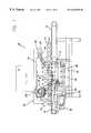
- FIG. 1is a front schematic plan view of the in-line continuous feed sleeve labeling machine of the present invention.
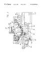
- FIG. 2is a front schematic plan view of the present invention.
- FIG. 3is a top schematic plan view of the present invention.
- FIG. 4is a top schematic plan view of the present invention.
- FIG. 5is a left side schematic plan view of the present invention.
- FIG. 6is a left side schematic plan view of an alternative embodiment of the present invention.
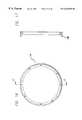
- FIG. 7is a top perspective view of the iris carrier, or armature, of the present invention.
- FIG. 8is a top plan view of the iris carrier of FIG. 7 shown in an open or dilated position.
- FIG. 9is a top plan view of the iris carrier of FIG. 7 shown in a contracted position with the radial arms extending inward towards the center of the iris carrier.
- FIG. 10is a side and partial cross-sectional view of the iris carrier of FIG. 9 taken generally along line 10 — 10 .
- FIG. 11is a top plan view of an alternate embodiment of the iris carrier of FIG. 7 of the present invention showing four (4), rather than ten (10), radial arms.
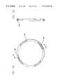
- FIG. 12is a top plan view of the link ring used in the iris carrier of FIG. 7 .
- FIG. 13is a side cross-sectional view of the link ring of FIG. 12 taken generally along line 13 — 13 .
- FIG. 14is a top plan view of the wear ring used in the iris carrier of FIG. 7 .
- FIG. 15is a side cross-sectional view of the wear ring of FIG. 14 taken generally along line 15 — 15 .
- FIG. 16is a top plan view of an alternative embodiment of the wear ring of the present invention.
- FIG. 17is a side cross-sectional view of the wear ring of FIG. 16 taken generally along line 17 — 17 .
- FIG. 18is a top plan view of the bottom chassis of the iris carrier of FIG. 7 .
- FIG. 19is a side cross-sectional view of the bottom chassis of FIG. 18 taken generally along line 19 — 19 .
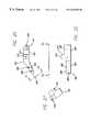
- FIG. 20is a top plan view of the extending radial arm of the iris carrier of FIG. 7 .
- FIG. 21is a side view of the extending radial arm of FIG. 20 taken generally along line 21 — 21 .
- FIG. 22is a side and partial cut-away view of the extending radial arm of FIG. 20 taken generally along line 22 — 22 .
- FIG. 23is a top plan view of the linkage bar shown in the iris carrier of FIG. 7 .
- FIG. 24is a side view of the linkage bar of FIG. 23 showing the end holes in phantom.
- FIG. 25is a side elevational view of the finger rod of the iris carrier of FIG. 7 .
- FIG. 26is an end elevational view of the finger rod of FIG. 25 .
- FIG. 27is a top plan view of the finger rod of FIG. 25 .
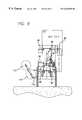
- FIG. 28is a side elevational view of the pedestal used in the present invention as shown in FIG. 1 . Internal apertures and structures are shown in phantom.
- FIG. 29is a top plan view of the pedestal shown in FIG. 28 .
- FIG. 30is a top plan view of the base of the pedestal shown in FIG. 28 .
- FIG. 31is a side view of the connecting portion of the pedestal base shown in FIG. 30 taken generally along line 31 — 31 .
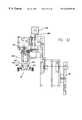
- FIG. 32is a left side elevational view of the label feeder used in the present invention as shown in FIG. 1 .
- FIG. 33is a close-up view of the sleeve-transfer apparatus of the label feeder as it descends to place a label sleeve about the finger rods of the iris carrier.
- FIG. 34is a front schematic view of the label feeder shown coupled to the flywheel of the present invention.
- FIG. 34 ais an on-end view of the opening of a label sleeve S by the label feeder of FIG. 34 .
- FIG. 35is a schematic plan view of the nip rollers used to advance the sleeve labels in the present invention.
- FIG. 36is a partial upper right side perspective schematic view of the labeling machine of the present invention showing the container stabilizer.
- FIG. 37is a closer perspective view of the stabilizer of FIG. 36 encircled by circle 37 .
- FIG. 38is a flow chart showing the steps taken to transport a blank bottle B.
- FIG. 39is a flow chart showing the steps taken to deliver a label sleeve to a blank bottle B.
- the in-line continuous feed sleeve labeling machine 50is shown generally in its entirety in FIGS. 1-6.
- the in-line continuous feed sleeve labeling machine 50has the ability to sleeve or label bottles or containers continuously as they pass through the labeling machine 50 .
- the term “bottles”is synonymous with the term “containers” and related vessels
- labelis synonymous with the term “sleeve” and the like, including other indicia that can be attached by the present machine to bottles.
- the label feeder 52is positioned over a series of iris carriers 54 .
- the structure and operation of the iris carriers 54are discussed in more detail below.
- the iris carriers 54transport the sleeves to the bottles B as well as ensleeving them.
- the iris carriers 54are carried along a track 56 in a generally horizontal position without rocking or swaying.
- the iris carrier 54is pivotally attached to either side of the track 56 by means of spaced apart and offset pivots that may lie upon a diagonal in the plane defined by the iris carrier 54 .
- the track 56may be a pair of endless chains spaced apart from each other according to the width of the iris carrier 54 .
- the two lengths of endless chain making up the track 56are also offset from parallel by the distance between the iris carrier pivot points.
- the chainsare disposed so that as one of the iris carrier pivot points rounds a corner on one of the chain lengths, the other iris carrier pivot point is simultaneously also rounding its corresponding corner. Such a corner may be seen in FIG. 1 as indicated by reference number 58 .
- the series of iris carriers 54 and the track 56comprise an iris carrier system 60 .
- a pedestal system 64has a series of pedestals 66 conveyed in a cyclical manner on a pedestal track 68 .
- the bases of the pedestalsare pivotally connected to the pedestal track 68 in an offset manner, much in the same way as the iris carriers 54 are pivotally attached to the iris carrier track 56 .
- the operation of the pedestal system 64is synchronized and coordinated with the operation of the iris carrier track 56 so that the rate of horizontal travel between the iris carriers 54 is the same as the horizontal rate of travel for the pedestals 66 . In this way, a bottle B carried by a pedestal 66 may be vertically traversed by the iris carrier 54 without interfering with the travel of the bottle B upon the pedestal 66 .
- the pedestal system 64travels in a counterclockwise fashion while the iris carrier system 60 travels in a clockwise fashion. In this way, both the pedestal system 64 and the iris carrier system 60 are traveling in the same direction when they meet to, respectively, support and ensleeve a bottle B.
- a timing screw 70separates and aligns the bottles B for carrying upon the pedestal system 64 .
- a low-friction transition plate 72allows the low-friction timing screw 70 to move a bottle B from an input conveyor 74 to one of the pedestals 66 of the pedestal system 64 .
- the timing screw 70allows for a flood feed system in and to the in-line continuous feed sleeve labeling machine 50 , where a number of individual bottles B are bunched about the timing screw 70 .
- the timing screw 70then picks up a single one of several adjacent available bottles B and moves it into synchronized position for pickup by the pedestal system 64 and ensleevement by an ensleeved iris carrier 54 .
- the bottle Bis then transported to an exit conveyor 76 .
- the iris carrier 54As the iris carrier 54 is making its vertical ascent up from the bottom of bottle B, it may be possible to use the horizontal motion of the iris carrier 54 to carry or move the bottle B horizontally/laterally from its associated pedestal 66 and onto the exit conveyor 76 .
- a low-friction transition platesuch as the one used for introduction of the bottles B to the pedestal system 64 , may be used.
- the horizontal rate of travel of the iris carrier 54is the same as the horizontal rate of travel of bottle B.
- bottlesare ensleeved as follows. Bottles are transported to the in-line continuous feed sleeve labeling machine 50 of the present invention by the input conveyor 74 or otherwise. The bottles may be transported in a single-file fashion or via a flood feed. One, single bottle B is then picked up by the timing screw 70 at one of its furrows, so that only one bottle B is transported to the pedestal system 64 at any one time.
- the timing screw 70is constructed so as to engage the bottle B generally at its center of mass so that there are few torques upon the bottle B.
- the bottle Bmay be trapped between the timing screw 70 and a rail or guard on the opposite side.
- the bottle Bis then moved over the low-friction transition plate 72 and onto a pedestal 66 of the pedestal system 64 .
- a sleeved iris carrier 54moves synchronously with the bottle B.
- the iris carrier 54 with its sleevedescends about the bottle B.
- the sleeveis generally disposed about the central section of the bottle B. This central section is generally the desired section where the label is to be applied. Fingers present on the iris carrier 54 contract, causing the top of the sleeve or label to engage the exterior of the bottle B. The label (by friction fit about the bottle B or otherwise) begins to adhere to the side of the bottle B.
- the fingers of the iris carrier 54are generally smooth to provide a low-friction surface engaging the interior surface of the sleeve. As the sleeve adheres (at least slightly, but possibly more so) to the side of the bottle B, the iris carrier 54 and its sleeve-carrying fingers begin to disengage the sleeve, leaving it behind upon the bottle B. As the iris carrier 54 continues to descend towards the bottom of the bottle B and the top of the pedestal 66 , the fingers increasingly disengage the sleeve, leaving it to circumscribe the exterior of the bottle at its central section.
- the container stabilizer 350 shown in FIGS. 36 and 37may help to disengage the label from the iris carrier 54 and apply it to the bottle B.
- the location of the container stabilizeris such that it may catch a top margin of the label and hold it to the bottle B as the iris carrier 54 slides out from within the label.
- the iris carrier 54descends until the sleeve-carrying fingers completely disengage the sleeve. At this point, the fingers then dilate, moving outward to expand the central aperture present in the iris carrier 54 the iris carrier 54 begins its upward ascent about the bottle B from its base to its top. In so traveling, the iris carrier 54 may help the bottle B to make the transition from the pedestal system 64 to the exit conveyor 76 . Once the iris carrier 54 has fully disengaged the bottle B by ascending past its top, the iris carrier 54 is ready to receive another sleeve from the label feeder 52 and to sleeve another bottle.
- the entirety of the in-line continuous feed sleeve labeling machine 50 of the present inventionmay be powered and synchronized by a single AC motor 80 .
- the motor 80may be a three-phase industrial-type motor as is known in the art.
- the motor 80provides sufficient power to efficiently, consistently, and reliably power the label feeder 52 , the iris carrier system 60 , the pedestal system 64 , the timing screw 70 , the input conveyor 74 , and the output or exit conveyor 76 .
- a reduction gear 82may be attached to the output shaft of the motor 80 to drive a timing belt 84 .
- the timing belt 84may then drive (from the flywheel system 86 ) gearing and belt systems coupled to the flywheel system 86 . These in turn drive the input conveyor 74 , the timing screw 70 , the pedestal system 64 , the iris carrier system 60 , and the exit conveyor 76 .
- shaft extensions from such gears, sprockets, wheels, or the likeextend away from the operational portion into a bearing so that the corresponding part (wheel, gear, sprocket, etc.) does not wobble, nutate, articulate, or the like when it turns.
- FIGS. 3-6show these shaft extensions 90 .
- a torque overload protection mechanism 100disengages when high torque occurs in the system, such as a jam in the gearing or otherwise.
- a disk in the torque overload protector 100pushes off from a main section and trips a cutoff switch to immediately stop the in-line continuous feed sleeve labeling machine 50 of the present invention.
- the cutoff switch(not shown) may use regenerative braking or dynamic braking of the motor in order to stop the machine 50 as soon as possible.
- the risk of injuryis reduced as is the degree of injuries sustained should a body part (such as a finger or arm) become stuck or caught in the labeling machine 50 .
- the components of the labeling machine 50are also protected from injury as excessive torque or force is quickly detected and contemporaneously relieved with the cessation of operations.
- the overload protection mechanism 100may be easily reset to provide quick restarts and minimize downtime once the jam has been cleared.
- the stepper motor 104serves to control a nip roller 106 having a manual operation knob 108 .
- the nip roller 106receives a ribbon or stream of labels from label rollers 112 (FIG. 5) held in place by a stand or label holder 114 supporting spools of labels 112 on rods or shafts 116 .
- the nip roller 106controls the travel of the unspooled label web into the label machine 50 of the present invention.
- the stepper motor 104controls the length and rate of travel of the labels.
- the stepper motor 104causes the labels to pause briefly so that they may be cut by a guillotine-type or other mechanism as the terminal sleeve label being severed is engaged by sleeve feeding arms 120 .
- the sleeve feeding arms 120are shown in more detail in FIGS. 32 and 33.
- the stepper motor 104is also shown in more detail in FIG. 34 with the nip roller 106 shown in more detail in FIG. 35 .
- a weighted blanket or the like(not shown) can engage and travel with the top of the bottles B in order to stabilize them upon the pedestal 66 .
- the stabilization blanket or padmay be of an endless configuration that moves on rollers in a loop at the same horizontal rate of travel as the bottles B.
- the pedestal 66may incorporate a vacuum system whereby the base of the bottle B is held in place on the pedestal as suction is present at the top of the pedestal 66 .
- the pedestal Pmay have a top that engages a variety of bottle sizes, such that the utility of the labeling machine 50 of the present invention is enhanced due to the variety of bottles or containers B it can ensleeve. Both large and small bottles B are shown in FIG. 1 on the pedestals 66 . With different sizes or volumes of bottles B, certain adjustments may necessarily need to be made. However, the labeling machine 50 of the present invention is contemplated as being able to handle bottles of any size although certain parts may need to be remanufactured for very large or very small bottles. Despite such re-manufacture, the basic and fundamental portions of the labeling machine 50 of the present invention as set forth herein should be applicable to such bottles B.
- FIG. 7shows in perspective view one of the iris carriers 54 of the present invention.
- the iris carrier 54has a base 130 , which provides the basic chassis for the iris carrier 54 of the present invention.
- the iris carrier 54has a generally open central portion 132 through which the bottle B passes during the ensleevement process.
- the open nature of this aperture 132is important as the iris carrier 54 must pass about the exterior of the bottle B in order to ensleeve it properly at its central portion. Consequently, accommodations and certain engineering requirements are necessary in order to provide the articulation of the iris carrier components to achieve proper, reliable, and adjustable ensleevement.
- FIG. 10A cross-section of the iris carrier 54 is shown in FIG. 10 .
- the base 130 of the iris carrier 54supports a wear ring 134 that circumscribes the central aperture 132 .
- a link ring 136Atop the wear ring 134 is a link ring 136 which slides rotatingly atop the wear ring 134 in order to articulate the radial arms 140 with their attached finger rods 142 .
- the radial arms 140are pivotally coupled to the base 130 and are articulably coupled to the link ring 136 by a linkage bar 144 .
- the linkage bar 144is pivotally coupled to both the link ring 136 and the radial arm 140 .
- FIGS. 8 and 9show the dilated (FIG. 8) and contracted (FIG. 9) configurations of the iris carrier 54 .
- FIGS. 8 and 9also show the offset nature of the pivotable connections 150 that the iris carrier 54 makes with the iris carrier track 56 .
- the pivotable connections 150are the means by which attachment of the iris carrier 54 can be made with the iris carrier track 56 in order to keep the iris carrier 54 in a horizontal and bottle-engaging position.
- This horizontal offset 152maintains the iris carrier 54 in a horizontal position without swaying, jiggling, or rocking as it travels upon the iris carrier track 56 .
- the rotation about the axis 154 of the pivotable connection 150would cause the other side of the iris carrier 54 to travel in the opposite direction.
- the opposite and right side of the iris carrier 54would have to swing downward.
- the opposite (right) pivotable connection 150holds the opposite side in place, preventing any rotation about the axis 154 of the left pivotable connection 150 .
- the horizontal offset 152must be accommodated by the iris carrier track 56 and the opposed chains or other carriers must be horizontally offset by the same offset 152 (FIG. 9) which is present at the iris carrier 54 .
- the two pivotable connections 150allow the iris carrier 54 as a whole to turn with respect to the track 56 .
- the iris carrier 54cannot pivot, turn, rock, or sway with respect to one individual side of the track 56 . Consequently, a horizontal position is maintained by the iris carrier 54 throughout its travel on the iris carrier track 56 .
- the pedestals 66 and the pedestal system 64as they travel upon the pedestal track 68 .
- a cam roller 160may be attached to the link ring 136 .
- the cam roller shown in FIG. 7is tilted at an angle and generally corresponds to the cam roller necessary for the slight contraction of the finger rods 142 necessary for disengaging the sleeve from the iris carrier 54 as the sleeve engages the bottle B.
- Another cammay be attached to the link ring 136 in order to fully contract the finger rods to a configuration such as that shown in FIG. 9.
- a spring or other biasing meansholds the iris carrier 54 in the dilated configuration as shown in FIG. 8 by default.
- the link ring 136When one of the cam rollers 160 , 162 is engaged by a cam, it causes the link ring 136 to pivot with respect to the iris carrier 54 as a whole about its central axis perpendicular to the plane of the central aperture 132 . As shown in FIG. 10, the link ring 136 shares a small common shoulder or collar 170 with the radial arm 140 . The link ring 136 is consequently constrained to travel in a circle outside the several radial arms 140 . Additionally, the linkage bars 144 constrain the motion of the link ring 136 to circumferential path motion about the iris carrier 54 and above the wear ring 134 .
- the linkage bars 144are generally longer than the distance between the radial arms attachment 172 to the base 130 and the pivotable attachment 174 of the linkage bar 144 with the radial arm 140 , the linkage bar 144 can extend the radial arms 140 only a certain distance into the central aperture 132 of the iris carrier 54 .
- the articulation of the radial arms 140is controlled by the degree with which one of the cam rollers 160 , 162 articulates the link ring 136 with respect to the iris carrier 54 .
- FIG. 11shows an alternative embodiment of the iris carrier 54 of the present invention, having four rather than ten radial arms 140 .
- the use of a lesser number of radial arms 140may be appropriate in some circumstances and may provide some efficiencies and mechanical simplicities over having several or more radial arms 140 .
- FIGS. 12 and 13show the link ring 136 that slides over the wear ring 134 to provide the articulation of the radial arms 140 through the linkage bars 144 .
- the link ring 136has a number of apertures or holes 180 through which fasteners, such as the fasteners upon which the linkage bars 144 pivot, may be attached.
- FIGS. 14 and 15show views of the wear ring 134 .
- the wear ring 134not only has through holes 182 , but also furrows, gaps, or radial slots 184 .
- the radial slots 184generally allow the upper link ring 136 slidable attachment with the lower wear ring 134 .
- a shoulder-type boltmay pass through the lower wear ring 134 and project upwardly through the link ring 136 and may also pass through the linkage bar 144 before threading through a nut or the like.
- the shoulder of the shoulder boltmay pass through the radial slot 184 , allowing the shoulder bolt to slide along the length of the radial slot 184 .
- the link ring of the shoulder bolthas limited travel through the link ring 136 , however, it can travel along the length of the radial slot 184 in the wear ring 134 .
- the shoulder boltthen limits the relative rotational travel between the lower wear ring 134 and the upper link ring 136 while allowing the upper link ring 136 slidable attachment to the lower wear ring 134 .
- the lower wear ring 134may be coupled or fixed to the iris carrier base 130 so as to provide a stable be and mechanically coupled linkage by which the iris carrier 54 may suitably and connectably articulate.
- the wear ring 134has no radial slots.
- the upper link ring 136may be coupled to the lower wear ring 134 by means of bearing spools placed around the periphery of the two rings 134 , 136 .
- the wear ring 134may serve as a self-lubricating junction between the link ring 136 and the base 130 .
- Self-lubricating or low-friction plasticssuch as polypropylene or substances such as Teflon® may provide the material for the wear ring 134 .
- Fasteners or other means of attachmentmay be used in order to provide the pivoting and/or pivotable connections necessary to achieve the present invention.
- FIGS. 16 and 17show an alternative embodiment of the wear ring 134 without the furrows 184 , yet having an extending flange 188 that may serve to provide containment for the link ring 136 so that it may travel within the confines defined by the circular area defined by the flange 188 of the wear ring 134 .
- FIGS. 18 and 19show the base, bottom, or chassis 130 of the iris carrier 54 .
- the base 130has an outer ring 190 and an inner ring 192 .
- the transition between the inner ring 192 and the outer ring 190provides a shoulder 198 (FIG. 10) against which the radial arms 140 can rest in conjunction with the wear ring 134 and the link ring 136 as shown in FIG. 10.
- a number of apertures 194are present in the inner ring 192 through which fasteners may be threadably attached to the pivotable radial arms 140 .
- the holes 196 present on the outer ring 190serve to provide pivotable fastener points for the linkage bars 144 as shown in FIG. 10 .
- FIGS. 20-22show one of the radial arms 140 .
- the radial arm 140has base aperture or hole 200 through which it is pivotally attached to the iris carrier base 130 .
- the radial arm 140extends forwardly from the base hole 200 to a bend 203 of approximately 36° in order to provide a base extension 202 that becomes an extension 204 for the finger rod 142 .
- the finger rod 142fits into a finger rod aperture 206 which receives the base end of the finger rod. Screw holes 208 may be present in order to removably attach the finger rod 142 as by recessed screws or the like.
- the radial arm 140has an upward extension 210 that rises above the base extension 202 to provide a horizontal or flat height between the pivotable points of attachment for the linkage bar 144 .
- the radial arm 140then descends as it travels out to the terminal end of the finger rod extension 204 .
- the upward linkage bar support 210has generally at its center a threaded hole 212 into which a fastener threads in order to pivotably hold the radial arm end of the linkage bar 144 in place.
- the linkage bar 144has two symmetrical holes 220 formed at opposite ends. These holes 220 are those that are used to attach the linkage bar 144 to the link ring 136 at one end and to the radial arm 140 at the other. In one embodiment, the linkage bar 144 may be approximately 15 ⁇ 8′′ to 13 ⁇ 4′′ long and approximately 1 ⁇ 2′′ wide.
- the finger rod 142is shown in a variety of views.
- the finger rod 142is generally a smooth curved piece of strong material, such as metal or strong plastic.
- the finger rod 142has a horizontally extending base portion 226 and a vertically extending finger portion 228 .
- the horizontal base 226is generally circular in nature while the cross-section of the upwardly extending finger portion 228 may be flattened on its sides to provide outward structural support able to withstand the restoring force or pressure of the sleeve or label when the sleeve is stretched outwardly by the iris carrier 54 .
- the top 230 of the finger rod 142is generally rounded to ensure that it does not snag or catch upon the sleeve or label.
- FIGS. 28 and 29show views of a pedestal 66 .
- Each pedestal 66has a top 240 , a central pillar 242 , and a base 244 .
- the pivotable pedestal base connectors 246that are generally configured and operated in a manner similar to the pivotable iris carrier connectors 150 .
- the offset of the two pivotable pedestal base connectors 246may be the same as that for the pivotable iris carrier connectors 150 .
- the pivotable pedestal base connectors 246hold the pedestal 66 in an upright manner throughout its travel along the pedestal track 68 .
- the pedestal base 244is generally minimal and provides a span between the two pivotable connectors 246 in order to support the central pillar 242 and its top 240 .
- the central pillar 242may be connected to the base 244 by means of threaded fasteners or the like through holes 248 present in the base 244 .
- Corresponding holes 250 for such threaded fasteningare present in the central pillar 242 that match those holes 248 present in the pedestal base 244 .
- the pedestal top 240may have a hole or aperture 254 through which a threaded or other fastener can pass in order to thread into the top of the central pillar 242 in a hole or aperture 252 present there.
- a vacuum linemay be passed through the pivotable connectors 246 or otherwise to provide a vacuum or suction at the pedestal top 240 .
- Other means by which a vacuum may be provided at the pedestal top 240are also contemplated in the present invention. With the use of such a vacuum, bottles placed upon the pedestal top 240 may be better held in place in order to better ensure proper sleeving.
- the pedestal top 240may be reconfigurable in order to receive the bases of different types of bottles. Should a bottle base have a specific design or configuration for its base, the top of the pedestal 240 may be interchangeably removed and substituted for a pedestal top 240 that better conforms to the bottle bottom.
- FIGS. 30 and 31show additional views of the pedestal base 244 .
- FIG. 32shows a side view of the label feeder 52 .
- label feedersare known in the art.
- U.S. Pat. No. 5,483,783 issued to Lerner et al. on Jan. 16, 1996describes a label feeder, as do other patents known in the art.
- Such label feedersprovide adequate means by which labels may be delivered to the iris carrier 54 of the present invention.
- a stepper motor 104drives a belt 260 to control the motion of the nip roller 106 that controls the progress of a web or ribbon of sleeves from the label or sleeve spool or roll 112 .
- the terminal sleeveUpon passing through the nip roller 106 , the terminal sleeve is engaged by a pair of articulating arms 264 , 266 , that end in pneumatically-operated suction graspers 268 , 270 .
- the terminal sleevepasses through an open guillotine or other cutting device disposed between the nip roller 106 and the now-extending terminal end of the label webbing.
- the stepper motor 104Upon extending outward a predetermined amount, the stepper motor 104 temporarily stops in place and the articulating arms 264 , 266 cause the suction graspers 268 , 270 to engage the sleeve and place some slight tension upon the terminal sleeve.
- the open guillotinethen closes to sever the terminal sleeve from the main web or roll.
- the nip roller 106holds the sleeve webbing in place during the cutting process.
- FIG. 34 ashows the suction graspers 268 , 270 opening a sleeve S.
- FIG. 33shows the placement of a sleeve S on the finger rods 142 .
- the stepper motor 104then advances the continuous web of labels or sleeves through the nip rollers 106 and the now-open gap of the guillotine cutter.
- the vacuum provided upon the suction graspers 268 , 270ceases so that the sleeve is released upon the iris carrier 54 .
- the articulating arms 264 , 266then retract to grasp (by the suction graspers 268 , 270 ) the next label or sleeve.
- the label feeder 52is actuated by a bascale or seesaw bar 280 that is pivotally attached at its center 282 to the labeling machine 50 .
- the far end 284 of the bascale bar 280is rollably coupled to the flywheel 86 and rides in a groove 286 engraved therein.
- the bascale bar groove 286is generally elliptical in nature extending outward toward the perimeter of the flywheel 86 at one end 290 and traveling toward the center 292 of the flywheel 86 180° opposite of the near-circumferential end 290 .
- the terminal end 284 of the bascale bar 280is held in a radially fixed position relative to the center point 282 . Consequently, the turning of the flywheel 86 causes the terminal end 284 of the bascale bar 280 to oscillate up and down.
- the opposite terminal end 300 of the bascale bar 280travels in a path directly opposite of that to the flywheel terminal end 284 .
- the timing and actuation of the label feeder 52can be controlled by sensing or transmitting the oscillations of the label feeder terminal end 300 of the bascale bar 280 .
- the bascale bar 280converts the circular motion of the flywheel 86 to linear motion at the label feeder terminal end 300 of the bascale bar 280 .
- the motion of the terminal end 300 of the bascale bar 280may also serve to mechanically drive the articulating arms 264 , 266 and related structures of the label transfer system 262 (FIG. 33 ).
- the stepper motor 104 and the pneumatic operation of the suction graspers 268 , 270are operated in order to properly feed the labels from the continuous label web through the cutting process and onto the iris carriers 54 .
- FIG. 35shows a top view of the nip roller 106 , and to a certain extent, the guillotine device 312 .
- the piston 310 for the guillotine device 312is partially indicated in FIG. 35 .
- the guillotine blade 314is located below the nip roller 106 in order to receive the label sleeves.
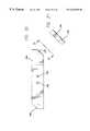
- FIG. 36shows a perspective view of a container stabilizer 350 that may be used in conjunction with the labeling machine 50 of the present invention.
- the container stabilizer 350is generally present at the end of the ensleeving portion of the process.
- the bottles Bapproach the container stabilizer 350 while being supported by pedestals 66 and circumscribed by the iris carriers 54 .
- FIG. 36shows schematically the presence and operation of the container stabilizer 350 with most of the other components of the labeling machine 50 removed for descriptive purposes.
- the bottles BAs the bottles B approach the container stabilizer 350 , they are supported by the associated pedestal 66 and circumscribed by the iris carrier 54 .
- the bottle Bmay be safely engaged by the container stabilizer 350 once the iris carrier 54 has descended below the container stabilizer 350 .
- the container stabilizer 350may then engage a top portion of the bottle B, aiding the labeling process.
- FIG. 37shows the container stabilizer 350 enlarged as indicated by circle 37 in FIG. 36 .
- the container stabilizer 350generally has a left belt 360 oppositely opposed to a right belt 362 .
- the overall length of the belts 360 , 362is generally as short as possible but long enough so that the iris carrier 54 may disengage the sleeve, leaving it about the bottle B.
- the belts 360 , 362slightly compress the bottle B between them, the belts 360 , 362 increasing in tension to accommodate the snug fit as the bottle B travels through the container stabilizer 350 .
- the belts 360 , 362may be driven by respective wheels 364 , 366 .
- the driving wheels 364 , 366turn the belts 360 , 362 about themselves and tension rollers 370 , 372 spaced apart from the driving wheels 364 , 366 .
- the driving wheels 364 , 366may be driven by shafts coupled to the ultimate mechanical or other power supply for the labeling machine 50 .
- Gearing mechanismssuch as those known in the art are able to transmit such mechanical power in a known fashion.
- the container stabilizer 350 and its left and right belts 360 , 362are synchronized to travel at the same horizontal rate as the iris carriers 54 and the pedestal 66 . This ensures that the bottles B are subject to the same horizontal velocity at their top (via the container stabilizer 350 ) and at their bottom (via the pedestal 66 ).
- the iris carrier 54 with its labeldescends about the bottle B.
- the container stabilizer 350may be positioned such that as the iris carrier 54 reaches the end of its downward travel, the stabilizer belts 360 , 362 B engage and compress the label at its top to the bottle B. The label is then fixed in position upon the bottle B by the slight compression and snug fit experienced between the bottle B and the container stabilizer 350 .
- the iris carrier 54may continue its downward travel and proceed to disengage the label, leaving it behind the bottle B.
- the finger rods 142may contract slightly, possibly coming into only light contact with the bottle B.
- the finger rods 142may then slide out from within the label as the iris carrier 54 descends towards the base of the bottle B.
- the tension applied to the labelis released and it may snugly encircle the bottle B.
- the labelmay then remain snugly attached to the bottle B or the bottle B with its label may be subject to a shrinking process as may be achieved by the application of heat.
- the bottle Bthen exits the container stabilizer 350 and proceeds onwardly to the output conveyor 76 .
- the container stabilizer 350generally cannot support the bottle B as it makes the transition from the pedestal 66 to the output conveyor 76 as it would interfere with the upward motion and return of the iris carriers 54 to the label feeder 52 .
- the “well” provided by the iris carrier track 56provides ample space within which the container stabilizer 350 may operate.
- extensionsmay project below the plain of the iris carrier 54 in order to better engage the bottle B as the iris carrier 54 initially descends about it.
- the extensionsmay flare outwardly so as to provide a greater area into which the top of the bottle B may fit and be guided into the iris carrier 54 .
- FIG. 38shows the steps taken in order to ensleeve a single bottle B.
- the processis basically the same for all such bottles traveling through the labeling machine 50 of the present invention.
- a blank bottle B 390is transported by the input conveyor 74 at step 392 .
- the input conveyor 74then transfers control of the bottle B to a timing screw 70 394 .
- the timing screw 70propels the bottle B over the low friction transition plate 72 396 .
- the bottle Bis then transferred to the pedestal 66 and is ensleeved by the iris carrier 54 398 .
- the timing screw 70may help to propel the bottle B onto the pedestal 66 .
- the iris carrier 54may have downwardly projecting extensions that serve to aid in the capture and transport of the bottle B, particularly with respect to the transition from the low friction transition plate 72 to the pedestal 66 .
- the pedestal 66carries the bottle B to the output conveyor 76 , which may also have a low friction transition plate similar to the one used to transport the bottle B onto the pedestal 66 .
- the transition from the pedestal 66 to the output conveyor 76is indicated by reference 400 .
- the bottle Bis then transported by the output conveyor 76 and away from the labeling machine 50 402 .
- the sleeved bottle Bis then ready for filling or boxing, depending upon whether the bottle B is empty or full and depending upon the position of the labeling machine 50 in the manufacturing line. This final step is indicated by reference 404 .
- FIG. 39provides an indication of the steps taken by the iris carrier 54 as it receives and delivers the sleeve or label and subsequently ensleeves the bottle B.
- the iris carrier 54initially approaches the label feeder 52 at an initial startup or after delivering a as prior sleeve to as bottle B 420 .
- the finger rods 142 of the iris carrier 54contract to receive a label 422 .
- the labelis then placed upon the finger rods 142 by the label feeder 52 424 . Once the label is placed upon the finger rods 142 , they dilate, or expand, to slightly tension and hold the label in place upon the iris carrier 54 426 .
- the iris carrier 54now holds a label in a secure disposition in order to transport the label to a bottle B for ensleeving.
- the iris carrier 54moves on the iris carrier track 56 in order to so engage the bottle B 428 .
- the iris carrier 54descends about the bottle B 430 .
- the sleeveis then carried forwardly and downwardly by the iris carrier 54 to a central portion of the bottle B 432 .
- the top margin of the labelmay be engaged by the belts 360 , 362 of the container stabilizer 350 . This serves to hold the label in place upon the bottle B while the iris carrier 54 continues to descend and disengage from the label.
- the sleeveengages the bottle B, it begins to disengage from the finger rods 142 of the iris carrier 54 434 .
- the finger rods 142fully disengage the sleeve, attaching it to bottle B 436 .
- the iris carrier 54may begin to ascend upwardly about the bottle B 438 .
- the iris carrier 54continues to ascend until it disengages the bottle B by traveling past its top 440 .
- the foregoing inventionprovides in-line means by which bottles may be sleeved at their central portions in a continuous manner.
- Pneumatic, mechanical, and electronic coordination of the system set forth hereinis believed to be within the knowledge and skill currently present in the art. Consequently, by the disclosure of the foregoing elements of the present invention and the indication that they operate synchronously with one another, the present invention is believed to have been made sufficiently clear for those having knowledge of the related art.
Landscapes
- Engineering & Computer Science (AREA)
- Manufacturing & Machinery (AREA)
- Labeling Devices (AREA)
Abstract
Description
Claims (3)
Priority Applications (2)
| Application Number | Priority Date | Filing Date | Title |
|---|---|---|---|
| US09/295,549US6263940B1 (en) | 1999-04-21 | 1999-04-21 | In-line continuous feed sleeve labeling machine and method |
| US09/767,168US6543514B2 (en) | 1999-04-21 | 2001-01-22 | In-line continuous feed sleeve labeling machine and method |
Applications Claiming Priority (1)
| Application Number | Priority Date | Filing Date | Title |
|---|---|---|---|
| US09/295,549US6263940B1 (en) | 1999-04-21 | 1999-04-21 | In-line continuous feed sleeve labeling machine and method |
Related Child Applications (1)
| Application Number | Title | Priority Date | Filing Date |
|---|---|---|---|
| US09/767,168Continuation-In-PartUS6543514B2 (en) | 1999-04-21 | 2001-01-22 | In-line continuous feed sleeve labeling machine and method |
Publications (1)
| Publication Number | Publication Date |
|---|---|
| US6263940B1true US6263940B1 (en) | 2001-07-24 |
Family
ID=23138178
Family Applications (1)
| Application Number | Title | Priority Date | Filing Date |
|---|---|---|---|
| US09/295,549Expired - LifetimeUS6263940B1 (en) | 1999-04-21 | 1999-04-21 | In-line continuous feed sleeve labeling machine and method |
Country Status (1)
| Country | Link |
|---|---|
| US (1) | US6263940B1 (en) |
Cited By (17)
| Publication number | Priority date | Publication date | Assignee | Title |
|---|---|---|---|---|
| US20030221396A1 (en)* | 2002-05-29 | 2003-12-04 | Kimberly-Clark Worldwide, Inc. | System and process for loading containers with formed product |
| US20040118904A1 (en)* | 2002-12-19 | 2004-06-24 | Sonoco Development, Inc. | Composite container having a hermetically sealed polymeric sleeve |
| US20050126118A1 (en)* | 2003-09-13 | 2005-06-16 | Volker Till | Beverage bottling plant for filling bottles with a liquid beverage filling material, having a container handling machine with interchangeable receptacles for the container mouth |
| US6996954B1 (en) | 2003-12-18 | 2006-02-14 | Axon Corporation | Horizontal sleeve applicator and method |
| US7060143B1 (en)* | 1999-04-30 | 2006-06-13 | Krones Ag | Method and device for applying wrap-around labels to objects |
| US20080081711A1 (en)* | 2006-09-29 | 2008-04-03 | Dewey Chauvin | Sporting good items including pre-printed graphics |
| US20080202076A1 (en)* | 2004-02-05 | 2008-08-28 | Protection Decoration Conditionnement Europe | Assembly for Positioning Sleeves on Products Such as Bottles |
| US20090266469A1 (en)* | 2004-12-20 | 2009-10-29 | Sidel S.P.A. | Process and device for automatically determining the beginning of a welding process for making tubular labels |
| US20100163164A1 (en)* | 2006-12-15 | 2010-07-01 | Ccl Label Gmbh | Stretch film sleeve label applicator |
| US20110198510A1 (en)* | 2004-08-12 | 2011-08-18 | Navotek Medical Ltd. | Localization of a radioactive source |
| US20130000263A1 (en)* | 2010-03-19 | 2013-01-03 | Fuji Seal International, Inc. | Fitting device and label opener |
| US20130213579A1 (en)* | 2010-10-21 | 2013-08-22 | Maurizio Pedercini | Device for forming and transferring a sleeve-like label to a container to be labeled |
| CN108973106A (en)* | 2018-07-27 | 2018-12-11 | 河南省鼎鼎实业有限公司 | A kind of reinforcing steel bar insulating casing wears method |
| US10287045B2 (en) | 2015-12-30 | 2019-05-14 | Axon Llc | Shrink sleeve applicator and related roller conveyor arrangement |
| US10640253B2 (en) | 2016-11-21 | 2020-05-05 | Axon Llc | Tubular banding applicator and method |
| CN112743825A (en)* | 2020-12-23 | 2021-05-04 | 上海亚大汽车塑料制品有限公司宁波分公司 | Heating circulation tunnel furnace for processing heat-shrinkable sheath and shrinkage method of heat-shrinkable sheath |
| US12144446B1 (en) | 2022-10-28 | 2024-11-19 | Michael J. Kretsinger | Combination marketing beverage container and game carrier |
Citations (96)
| Publication number | Priority date | Publication date | Assignee | Title |
|---|---|---|---|---|
| US2149377A (en) | 1937-04-01 | 1939-03-07 | Du Pont | Apparatus for capping bottles |
| US3652369A (en) | 1969-04-03 | 1972-03-28 | Romuald Rene Della Vite | Bottle feeding machine |
| US3850774A (en) | 1972-01-25 | 1974-11-26 | Weiss Maschf & Apparatebau J | Apparatus for labelling containers such as bottles |
| US3924387A (en) | 1975-04-03 | 1975-12-09 | Anatole E Konstantin | Banding machine |
| US3959065A (en) | 1974-04-25 | 1976-05-25 | Owens-Illinois, Inc. | Method and apparatus for producing plastic-covered containers |
| US3988182A (en) | 1972-12-27 | 1976-10-26 | American Can Company | Side seam orientation in can labeling machine |
| US4108710A (en) | 1972-02-14 | 1978-08-22 | B & H Manufacturing Company, Inc. | Apparatus for applying labels to containers |
| US4114774A (en) | 1976-12-23 | 1978-09-19 | Albert Scheidegger | Closure cap |
| US4163686A (en) | 1976-06-11 | 1979-08-07 | MA.CO S.a.s. di Saso Vittorio & C. | Labelling machine for applying a label, in particular a sealing band, to a container |
| US4177546A (en) | 1977-08-22 | 1979-12-11 | Wolfgang Geisinger | Apparatus for inserting a resilient band on a container |
| US4188249A (en) | 1977-04-05 | 1980-02-12 | Fuji Seal Industry Co., Ltd. | Package including an elastic container protector and a method and machine for fitting the protector |
| US4201029A (en) | 1978-08-14 | 1980-05-06 | Automated Packaging Systems, Inc. | Method and apparatus for packaging |
| US4201621A (en) | 1978-08-03 | 1980-05-06 | Label-Aire Inc. | Label applicator for irregularly shaped articles |
| US4202153A (en) | 1977-10-25 | 1980-05-13 | Automated Packaging Systems, Inc. | Method and apparatus for loading containers horizontally |
| US4231479A (en) | 1979-04-02 | 1980-11-04 | Albert Scheidegger | Closure caps adapted for distribution in a channel |
| US4245452A (en) | 1978-05-07 | 1981-01-20 | Fuji Seal Industry Co., Ltd. | Method and apparatus for wrapping an object in a sheet |
| US4247357A (en) | 1979-08-20 | 1981-01-27 | Owens-Illinois, Inc. | Container-base assembly machine |
| US4250686A (en) | 1978-10-23 | 1981-02-17 | Fuji Seal Industry Co. Ltd. | Cap seal fitting machine for a container |
| US4286421A (en) | 1979-01-18 | 1981-09-01 | Fuji Seal Industry Co., Ltd. | Method and machine for fitting a sleeve seal of a collapsed form over a container |
| US4287700A (en) | 1978-10-23 | 1981-09-08 | Fuji Seal Industry Co., Ltd. | Machine for fitting a sleeve seal of a flat form over a container |
| US4288968A (en) | 1979-12-03 | 1981-09-15 | Fuji Machinery Co., Ltd. | End sealing device for a plastic film in a packaging apparatus |
| US4288967A (en) | 1979-11-30 | 1981-09-15 | Fuji Machinery Co. Ltd. | Center sealing device for a plastic film in a packaging apparatus |
| US4290992A (en) | 1978-09-28 | 1981-09-22 | Fuji Seal Industry Co., Ltd. | Heat-shrinkable film tube with an internally ribbed closed end, and a method of making it |
| US4293364A (en) | 1978-09-14 | 1981-10-06 | Fuji Seal Industry Co., Ltd. | Method and machine for opening up a cylindrical film tube and fitting it over an object |
| US4323416A (en) | 1978-12-05 | 1982-04-06 | Malthouse Martin D | Labelling equipment |
| US4387553A (en) | 1981-01-02 | 1983-06-14 | Strub Eric W | Banding apparatus |
| US4398380A (en) | 1979-10-17 | 1983-08-16 | Fuji Pack System Ltd. | Packing apparatus |
| US4401020A (en) | 1981-12-16 | 1983-08-30 | Seaco Industries | Vegetable banding apparatus |
| US4412876A (en) | 1981-07-07 | 1983-11-01 | Automated Packaging Systems, Inc. | Labeling apparatus |
| US4445310A (en) | 1980-11-14 | 1984-05-01 | Scal Societe De Conditionnements En Aluminium | Process and installation for supplying caps to a closure machine |
| US4447280A (en)* | 1981-10-22 | 1984-05-08 | Malthouse Martin D | Labelling machine |
| US4470241A (en) | 1982-05-21 | 1984-09-11 | Salinas Valley Engineering & Manufacturing, Inc. | Apparatus for bunching, trimming, and banding vegetables |
| US4480984A (en) | 1983-09-09 | 1984-11-06 | Owens-Illinois, Inc. | Apparatus for heat-shrinking thermoplastic sleeves about glass containers |
| US4487650A (en) | 1983-03-12 | 1984-12-11 | Jagenberg Aktiengesellschaft | Labeling machine |
| US4497156A (en) | 1982-09-22 | 1985-02-05 | Ets Scheidegger W. & Cie | Method of and apparatus for enveloping moving articles |
| US4519186A (en) | 1982-03-03 | 1985-05-28 | Krones Aktiengesellschaft Hermann Kronseder Maschinenfabrik | Device for attaching tubular segments of plastic film on vessels |
| US4545174A (en) | 1982-04-19 | 1985-10-08 | Fuji Machinery Co., Ltd. | Timing adjusting device for packaging machines |
| US4570415A (en) | 1984-06-13 | 1986-02-18 | Mann Packing Co., Inc. | Vegetable banding apparatus |
| US4595544A (en) | 1983-04-30 | 1986-06-17 | Fuji Seal Industry Co. | Method of manufacturing a container covered with protective sheet |
| US4601155A (en) | 1984-09-14 | 1986-07-22 | Robert Alameda | Elastic band application system |
| US4612313A (en) | 1984-09-12 | 1986-09-16 | Boehringer Mannheim Gmbh | Pharmaceutical phenylacetonitrile derivatives |
| US4620888A (en) | 1984-09-04 | 1986-11-04 | Automated Packaging Systems, Inc. | Labeling apparatus |
| US4660357A (en) | 1984-12-28 | 1987-04-28 | Sleever International | Machine for placing sleeve around objects that are laid flat |
| US4691499A (en) | 1984-04-16 | 1987-09-08 | Fuji Machinery Company, Ltd. | Method of tensioning a web of packaging material |
| US4691835A (en) | 1982-12-20 | 1987-09-08 | Mueller Martin L | Tamper-evident sealed container and tamper-evident tube and bands and apparatus and method of making and using same |
| US4694633A (en) | 1985-05-21 | 1987-09-22 | Fuji Seal Industry Co., Ltd. | Film wrapping machine |
| US4724036A (en) | 1986-02-21 | 1988-02-09 | Owens-Illinois Plastic Products Inc. | Progressively ported vacuum drum for labeling machines |
| US4726168A (en) | 1985-05-08 | 1988-02-23 | Fuji Machinery Company, Ltd. | Method and apparatus for controlling a driving system in a packaging machine |
| US4729811A (en) | 1986-04-28 | 1988-03-08 | Owens-Illinois Glass Container Inc. | Infeed guide and roll-on belt for bottle labeling machine |
| US4731976A (en) | 1986-08-18 | 1988-03-22 | Nye Norman H | Method and apparatus for applying an elastic sleeve on an article |
| US4739605A (en) | 1986-06-19 | 1988-04-26 | Fuji Pack System Ltd. | Method and device for barrel-binding and packaging articles |
| US4765121A (en) | 1987-05-22 | 1988-08-23 | Pdc International Corporation | Banding apparatus with floating mandrel |
| US4775088A (en) | 1986-06-13 | 1988-10-04 | Fuji Machinery Company, Ltd. | Intermittent web feeding apparatus |
| US4801348A (en) | 1986-05-27 | 1989-01-31 | Fuji Seal Industry Co., Ltd. | Film supply apparatus |
| US4803829A (en) | 1986-01-27 | 1989-02-14 | Etablissements Scheidegger W. & Cie S.A. | Heat-shrunk threaded bottle cap |
| US4806187A (en) | 1986-06-18 | 1989-02-21 | Fujiyama Giken Co., Ltd. | Method and apparatus for successively applying thermoshrinkable tubular labels to containers |
| US4823538A (en) | 1986-05-30 | 1989-04-25 | Fuji Pack System Ltd. | Bagging machine |
| US4832774A (en) | 1988-05-06 | 1989-05-23 | Owens-Illinois Glass Container Inc. | Method and apparatus for applying wrap-around labels to containers |
| US4910941A (en) | 1987-11-20 | 1990-03-27 | Fuji Seal Industry Co., Ltd. | Method and apparatus for fitting a tube on a container or the like |
| US4944825A (en) | 1988-10-28 | 1990-07-31 | Automated Packaging Systems, Inc. | Labeling apparatus |
| US4947622A (en) | 1989-05-19 | 1990-08-14 | Packaging Systems International, Inc. | Apparatus and method for placing expansible lids on containers |
| US4964258A (en) | 1988-04-26 | 1990-10-23 | Fuji Machinery Company Ltd. | Packaging article inclusion-proofing device for end-sealing mechanism |
| US4977002A (en) | 1982-05-27 | 1990-12-11 | B & H Manufacturing Company, Inc. | System for applying heat shrink film to containers and other articles and heat shrinking the same |
| US4994135A (en) | 1988-06-03 | 1991-02-19 | Alfa Costruzioni Meccaniche S.P.A. | Device for rotation of the pedestals supporting bottles, or containers in general, in rotary labeling machines |
| US5006196A (en) | 1987-12-10 | 1991-04-09 | Protection Decoration Conditionnement Europe S.A. | Installation for applying labelling sleeves to articles such as cans |
| US5028293A (en) | 1987-02-18 | 1991-07-02 | Dinagraphics, Inc. | Continuous motion bottle decorating apparatus |
| US5043130A (en) | 1990-07-09 | 1991-08-27 | Fuji Seal Industry Co., Ltd. | Method of manufacturing labeled containers |
| US5060367A (en) | 1989-05-12 | 1991-10-29 | Protection Decoration Conditionnement Europe Sa | Machine for placing labelling sleeves on bottles or the like |
| US5070680A (en) | 1990-05-31 | 1991-12-10 | Fuji Seal Industry Co. Ltd. | Apparatus for opening a flat tube and fitting same on a container or the like |
| US5079902A (en) | 1988-12-28 | 1992-01-14 | Fuji Machinery Company Ltd. | Packaging method and apparatus |
| US5120392A (en) | 1991-05-20 | 1992-06-09 | Screen-Tech Inc. | Container transport and manipulator for use with a label or screen printing applier |
| US5174095A (en) | 1990-11-02 | 1992-12-29 | Fuji Photo Film Co., Ltd. | Method and apparatus for packaging a rolled web |
| US5192392A (en) | 1991-02-28 | 1993-03-09 | The Bottling Room, Inc. | Container labeler |
| US5197259A (en) | 1992-01-31 | 1993-03-30 | Menayan Victor V | Conveyor system and machine for applying tamper-evident bands to containers |
| US5326422A (en) | 1990-03-26 | 1994-07-05 | Hermann Kronseder | Labelling machine for labelling vessels |
| US5385002A (en) | 1989-11-24 | 1995-01-31 | Ag-Bag Corporation | Sheathing apparatus |
| US5398395A (en) | 1991-07-16 | 1995-03-21 | Graham Labelling Systems Limited | Banding apparatus and method |
| US5412859A (en) | 1992-08-14 | 1995-05-09 | Brown-Forman Corporation | Method for joining a booklet having an elastic band around a neck of a container |
| US5417794A (en) | 1992-07-21 | 1995-05-23 | Venture Packaging, Inc. | Apparatus for simultaneously disposing tubular labels on a plurality of bottles or other containers |
| US5421932A (en) | 1992-09-17 | 1995-06-06 | Fuji Seal Industry Co., Ltd. | Film tube for packaging articles and method for forming the same |
| US5433057A (en) | 1991-11-07 | 1995-07-18 | Automated Label Systems Company | High speed sleever |
| US5448876A (en) | 1993-06-04 | 1995-09-12 | Menayan; Victor V. | Machine for applying heat shrinkable bands to containers |
| US5477956A (en) | 1994-04-22 | 1995-12-26 | Automated Label Systems Company | Vessel processing system and process |
| US5478422A (en) | 1993-09-16 | 1995-12-26 | B & H Manufacturing Company, Inc. | Computer controlled turret type labeling machine |
| US5524420A (en) | 1994-08-17 | 1996-06-11 | Fuji Machinery Co., Ltd. | Horizontal form-fill-seal packaging machine and method of controlling the same |
| US5565057A (en) | 1993-11-05 | 1996-10-15 | Globe Machine Manufacturing Company | Web feed conveyor assembly in a wooden I-beam assembly machine and web feeding method |
| US5588278A (en) | 1995-06-27 | 1996-12-31 | Dole Fresh Vegetables Co. | Broccoli banding machine |
| US5613345A (en) | 1993-12-29 | 1997-03-25 | Cattleya Music Co., Ltd. | Waste disposing system and apparatus |
| US5665443A (en) | 1995-04-28 | 1997-09-09 | Fuji Seal, Inc. | Heat sensitive label for packaging a dry-cell battery |
| US5711135A (en) | 1993-03-15 | 1998-01-27 | Menayan; Victor V. | Heat-shrinkable band application machine |
| US5715651A (en) | 1994-08-23 | 1998-02-10 | Protection Decoration Conditionment | Process and machine for fitting stretchable labelling sleeves on bottles or the like |
| US5725966A (en) | 1996-01-25 | 1998-03-10 | Matsushita Electric Industrial Co., Ltd. | Heat sensitive jacket label for battery and battery with the same |
| US5737900A (en) | 1995-09-15 | 1998-04-14 | Pdc International Corporation | Banding method and apparatus with acceleration of band along floating mandrel aimed toward article to be banded |
| US5759337A (en) | 1994-06-21 | 1998-06-02 | Fuji Seal, Inc. | Container with a label thereon, and apparatus and method for manufacturing the same |
| US5775063A (en) | 1995-10-31 | 1998-07-07 | Fuji Machinery Co., Ltd. | Process and apparatus for assembly-packaging pellet-like articles |
| US5797247A (en) | 1994-08-31 | 1998-08-25 | Fuji Photo Film Co., Ltd. | Photosensitive material package and packaging apparatus for the same |
- 1999
- 1999-04-21USUS09/295,549patent/US6263940B1/ennot_activeExpired - Lifetime
Patent Citations (100)
| Publication number | Priority date | Publication date | Assignee | Title |
|---|---|---|---|---|
| US2149377A (en) | 1937-04-01 | 1939-03-07 | Du Pont | Apparatus for capping bottles |
| US3652369A (en) | 1969-04-03 | 1972-03-28 | Romuald Rene Della Vite | Bottle feeding machine |
| US3850774A (en) | 1972-01-25 | 1974-11-26 | Weiss Maschf & Apparatebau J | Apparatus for labelling containers such as bottles |
| US4108710A (en) | 1972-02-14 | 1978-08-22 | B & H Manufacturing Company, Inc. | Apparatus for applying labels to containers |
| US3988182A (en) | 1972-12-27 | 1976-10-26 | American Can Company | Side seam orientation in can labeling machine |
| US3959065A (en) | 1974-04-25 | 1976-05-25 | Owens-Illinois, Inc. | Method and apparatus for producing plastic-covered containers |
| US3924387A (en) | 1975-04-03 | 1975-12-09 | Anatole E Konstantin | Banding machine |
| US4163686A (en) | 1976-06-11 | 1979-08-07 | MA.CO S.a.s. di Saso Vittorio & C. | Labelling machine for applying a label, in particular a sealing band, to a container |
| US4114774A (en) | 1976-12-23 | 1978-09-19 | Albert Scheidegger | Closure cap |
| US4171736A (en) | 1976-12-23 | 1979-10-23 | Albert Scheidegger | Closure cap and apparatus for distributing such closure caps at high speed |
| US4188249A (en) | 1977-04-05 | 1980-02-12 | Fuji Seal Industry Co., Ltd. | Package including an elastic container protector and a method and machine for fitting the protector |
| US4177546A (en) | 1977-08-22 | 1979-12-11 | Wolfgang Geisinger | Apparatus for inserting a resilient band on a container |
| US4202153A (en) | 1977-10-25 | 1980-05-13 | Automated Packaging Systems, Inc. | Method and apparatus for loading containers horizontally |
| US4245452A (en) | 1978-05-07 | 1981-01-20 | Fuji Seal Industry Co., Ltd. | Method and apparatus for wrapping an object in a sheet |
| US4201621A (en) | 1978-08-03 | 1980-05-06 | Label-Aire Inc. | Label applicator for irregularly shaped articles |
| US4201029A (en) | 1978-08-14 | 1980-05-06 | Automated Packaging Systems, Inc. | Method and apparatus for packaging |
| US4293364A (en) | 1978-09-14 | 1981-10-06 | Fuji Seal Industry Co., Ltd. | Method and machine for opening up a cylindrical film tube and fitting it over an object |
| US4290992A (en) | 1978-09-28 | 1981-09-22 | Fuji Seal Industry Co., Ltd. | Heat-shrinkable film tube with an internally ribbed closed end, and a method of making it |
| US4250686A (en) | 1978-10-23 | 1981-02-17 | Fuji Seal Industry Co. Ltd. | Cap seal fitting machine for a container |
| US4287700A (en) | 1978-10-23 | 1981-09-08 | Fuji Seal Industry Co., Ltd. | Machine for fitting a sleeve seal of a flat form over a container |
| US4323416A (en) | 1978-12-05 | 1982-04-06 | Malthouse Martin D | Labelling equipment |
| US4286421A (en) | 1979-01-18 | 1981-09-01 | Fuji Seal Industry Co., Ltd. | Method and machine for fitting a sleeve seal of a collapsed form over a container |
| US4231479A (en) | 1979-04-02 | 1980-11-04 | Albert Scheidegger | Closure caps adapted for distribution in a channel |
| US4247357A (en) | 1979-08-20 | 1981-01-27 | Owens-Illinois, Inc. | Container-base assembly machine |
| US4398380A (en) | 1979-10-17 | 1983-08-16 | Fuji Pack System Ltd. | Packing apparatus |
| US4288967A (en) | 1979-11-30 | 1981-09-15 | Fuji Machinery Co. Ltd. | Center sealing device for a plastic film in a packaging apparatus |
| US4288968A (en) | 1979-12-03 | 1981-09-15 | Fuji Machinery Co., Ltd. | End sealing device for a plastic film in a packaging apparatus |
| US4445310A (en) | 1980-11-14 | 1984-05-01 | Scal Societe De Conditionnements En Aluminium | Process and installation for supplying caps to a closure machine |
| US4387553A (en) | 1981-01-02 | 1983-06-14 | Strub Eric W | Banding apparatus |
| US4412876A (en) | 1981-07-07 | 1983-11-01 | Automated Packaging Systems, Inc. | Labeling apparatus |
| US4447280A (en)* | 1981-10-22 | 1984-05-08 | Malthouse Martin D | Labelling machine |
| US4401020A (en) | 1981-12-16 | 1983-08-30 | Seaco Industries | Vegetable banding apparatus |
| US4401020B1 (en) | 1981-12-16 | 1985-10-08 | ||
| US4519186A (en) | 1982-03-03 | 1985-05-28 | Krones Aktiengesellschaft Hermann Kronseder Maschinenfabrik | Device for attaching tubular segments of plastic film on vessels |
| US4545174A (en) | 1982-04-19 | 1985-10-08 | Fuji Machinery Co., Ltd. | Timing adjusting device for packaging machines |
| US4470241A (en) | 1982-05-21 | 1984-09-11 | Salinas Valley Engineering & Manufacturing, Inc. | Apparatus for bunching, trimming, and banding vegetables |
| US4977002A (en) | 1982-05-27 | 1990-12-11 | B & H Manufacturing Company, Inc. | System for applying heat shrink film to containers and other articles and heat shrinking the same |
| US4497156A (en) | 1982-09-22 | 1985-02-05 | Ets Scheidegger W. & Cie | Method of and apparatus for enveloping moving articles |
| US4691835A (en) | 1982-12-20 | 1987-09-08 | Mueller Martin L | Tamper-evident sealed container and tamper-evident tube and bands and apparatus and method of making and using same |
| US4487650A (en) | 1983-03-12 | 1984-12-11 | Jagenberg Aktiengesellschaft | Labeling machine |
| US4595544A (en) | 1983-04-30 | 1986-06-17 | Fuji Seal Industry Co. | Method of manufacturing a container covered with protective sheet |
| US4480984A (en) | 1983-09-09 | 1984-11-06 | Owens-Illinois, Inc. | Apparatus for heat-shrinking thermoplastic sleeves about glass containers |
| US4691499A (en) | 1984-04-16 | 1987-09-08 | Fuji Machinery Company, Ltd. | Method of tensioning a web of packaging material |
| US4570415A (en) | 1984-06-13 | 1986-02-18 | Mann Packing Co., Inc. | Vegetable banding apparatus |
| US4620888A (en) | 1984-09-04 | 1986-11-04 | Automated Packaging Systems, Inc. | Labeling apparatus |
| US4612313A (en) | 1984-09-12 | 1986-09-16 | Boehringer Mannheim Gmbh | Pharmaceutical phenylacetonitrile derivatives |
| US4601155A (en) | 1984-09-14 | 1986-07-22 | Robert Alameda | Elastic band application system |
| US4660357A (en) | 1984-12-28 | 1987-04-28 | Sleever International | Machine for placing sleeve around objects that are laid flat |
| US4726168A (en) | 1985-05-08 | 1988-02-23 | Fuji Machinery Company, Ltd. | Method and apparatus for controlling a driving system in a packaging machine |
| US4694633A (en) | 1985-05-21 | 1987-09-22 | Fuji Seal Industry Co., Ltd. | Film wrapping machine |
| US4803829A (en) | 1986-01-27 | 1989-02-14 | Etablissements Scheidegger W. & Cie S.A. | Heat-shrunk threaded bottle cap |
| US4947627A (en) | 1986-01-27 | 1990-08-14 | Etablissements Scheidegger W. & Cie S.A. | Heat-shrunk threaded bottle cap |
| US4724036A (en) | 1986-02-21 | 1988-02-09 | Owens-Illinois Plastic Products Inc. | Progressively ported vacuum drum for labeling machines |
| US4729811A (en) | 1986-04-28 | 1988-03-08 | Owens-Illinois Glass Container Inc. | Infeed guide and roll-on belt for bottle labeling machine |
| US4801348A (en) | 1986-05-27 | 1989-01-31 | Fuji Seal Industry Co., Ltd. | Film supply apparatus |
| US4823538A (en) | 1986-05-30 | 1989-04-25 | Fuji Pack System Ltd. | Bagging machine |
| US4775088A (en) | 1986-06-13 | 1988-10-04 | Fuji Machinery Company, Ltd. | Intermittent web feeding apparatus |
| US4806187A (en) | 1986-06-18 | 1989-02-21 | Fujiyama Giken Co., Ltd. | Method and apparatus for successively applying thermoshrinkable tubular labels to containers |
| US4739605A (en) | 1986-06-19 | 1988-04-26 | Fuji Pack System Ltd. | Method and device for barrel-binding and packaging articles |
| US4731976A (en) | 1986-08-18 | 1988-03-22 | Nye Norman H | Method and apparatus for applying an elastic sleeve on an article |
| US5028293A (en) | 1987-02-18 | 1991-07-02 | Dinagraphics, Inc. | Continuous motion bottle decorating apparatus |
| US4765121A (en) | 1987-05-22 | 1988-08-23 | Pdc International Corporation | Banding apparatus with floating mandrel |
| US4910941A (en) | 1987-11-20 | 1990-03-27 | Fuji Seal Industry Co., Ltd. | Method and apparatus for fitting a tube on a container or the like |
| US5006196A (en) | 1987-12-10 | 1991-04-09 | Protection Decoration Conditionnement Europe S.A. | Installation for applying labelling sleeves to articles such as cans |
| US4964258A (en) | 1988-04-26 | 1990-10-23 | Fuji Machinery Company Ltd. | Packaging article inclusion-proofing device for end-sealing mechanism |
| US4832774A (en) | 1988-05-06 | 1989-05-23 | Owens-Illinois Glass Container Inc. | Method and apparatus for applying wrap-around labels to containers |
| US4994135A (en) | 1988-06-03 | 1991-02-19 | Alfa Costruzioni Meccaniche S.P.A. | Device for rotation of the pedestals supporting bottles, or containers in general, in rotary labeling machines |
| US4944825A (en) | 1988-10-28 | 1990-07-31 | Automated Packaging Systems, Inc. | Labeling apparatus |
| US5079902A (en) | 1988-12-28 | 1992-01-14 | Fuji Machinery Company Ltd. | Packaging method and apparatus |
| US5060367A (en) | 1989-05-12 | 1991-10-29 | Protection Decoration Conditionnement Europe Sa | Machine for placing labelling sleeves on bottles or the like |
| US4947622A (en) | 1989-05-19 | 1990-08-14 | Packaging Systems International, Inc. | Apparatus and method for placing expansible lids on containers |
| US5385002A (en) | 1989-11-24 | 1995-01-31 | Ag-Bag Corporation | Sheathing apparatus |
| US5326422A (en) | 1990-03-26 | 1994-07-05 | Hermann Kronseder | Labelling machine for labelling vessels |
| US5070680A (en) | 1990-05-31 | 1991-12-10 | Fuji Seal Industry Co. Ltd. | Apparatus for opening a flat tube and fitting same on a container or the like |
| US5043130A (en) | 1990-07-09 | 1991-08-27 | Fuji Seal Industry Co., Ltd. | Method of manufacturing labeled containers |
| US5174095A (en) | 1990-11-02 | 1992-12-29 | Fuji Photo Film Co., Ltd. | Method and apparatus for packaging a rolled web |
| US5192392A (en) | 1991-02-28 | 1993-03-09 | The Bottling Room, Inc. | Container labeler |
| US5120392A (en) | 1991-05-20 | 1992-06-09 | Screen-Tech Inc. | Container transport and manipulator for use with a label or screen printing applier |
| US5398395A (en) | 1991-07-16 | 1995-03-21 | Graham Labelling Systems Limited | Banding apparatus and method |
| US5483783A (en) | 1991-11-07 | 1996-01-16 | Automated Label Systems Company | High speed sleever |
| US5433057A (en) | 1991-11-07 | 1995-07-18 | Automated Label Systems Company | High speed sleever |
| US5197259A (en) | 1992-01-31 | 1993-03-30 | Menayan Victor V | Conveyor system and machine for applying tamper-evident bands to containers |
| US5417794A (en) | 1992-07-21 | 1995-05-23 | Venture Packaging, Inc. | Apparatus for simultaneously disposing tubular labels on a plurality of bottles or other containers |
| US5412859A (en) | 1992-08-14 | 1995-05-09 | Brown-Forman Corporation | Method for joining a booklet having an elastic band around a neck of a container |
| US5421932A (en) | 1992-09-17 | 1995-06-06 | Fuji Seal Industry Co., Ltd. | Film tube for packaging articles and method for forming the same |
| US5711135A (en) | 1993-03-15 | 1998-01-27 | Menayan; Victor V. | Heat-shrinkable band application machine |
| US5448876A (en) | 1993-06-04 | 1995-09-12 | Menayan; Victor V. | Machine for applying heat shrinkable bands to containers |
| US5478422A (en) | 1993-09-16 | 1995-12-26 | B & H Manufacturing Company, Inc. | Computer controlled turret type labeling machine |
| US5565057A (en) | 1993-11-05 | 1996-10-15 | Globe Machine Manufacturing Company | Web feed conveyor assembly in a wooden I-beam assembly machine and web feeding method |
| US5613345A (en) | 1993-12-29 | 1997-03-25 | Cattleya Music Co., Ltd. | Waste disposing system and apparatus |
| US5477956A (en) | 1994-04-22 | 1995-12-26 | Automated Label Systems Company | Vessel processing system and process |
| US5759337A (en) | 1994-06-21 | 1998-06-02 | Fuji Seal, Inc. | Container with a label thereon, and apparatus and method for manufacturing the same |
| US5524420A (en) | 1994-08-17 | 1996-06-11 | Fuji Machinery Co., Ltd. | Horizontal form-fill-seal packaging machine and method of controlling the same |
| US5715651A (en) | 1994-08-23 | 1998-02-10 | Protection Decoration Conditionment | Process and machine for fitting stretchable labelling sleeves on bottles or the like |
| US5797247A (en) | 1994-08-31 | 1998-08-25 | Fuji Photo Film Co., Ltd. | Photosensitive material package and packaging apparatus for the same |
| US5665443A (en) | 1995-04-28 | 1997-09-09 | Fuji Seal, Inc. | Heat sensitive label for packaging a dry-cell battery |
| US5588278A (en) | 1995-06-27 | 1996-12-31 | Dole Fresh Vegetables Co. | Broccoli banding machine |
| US5737900A (en) | 1995-09-15 | 1998-04-14 | Pdc International Corporation | Banding method and apparatus with acceleration of band along floating mandrel aimed toward article to be banded |
| US5775063A (en) | 1995-10-31 | 1998-07-07 | Fuji Machinery Co., Ltd. | Process and apparatus for assembly-packaging pellet-like articles |
| US5725966A (en) | 1996-01-25 | 1998-03-10 | Matsushita Electric Industrial Co., Ltd. | Heat sensitive jacket label for battery and battery with the same |
Cited By (27)
| Publication number | Priority date | Publication date | Assignee | Title |
|---|---|---|---|---|
| US7060143B1 (en)* | 1999-04-30 | 2006-06-13 | Krones Ag | Method and device for applying wrap-around labels to objects |
| US20030221396A1 (en)* | 2002-05-29 | 2003-12-04 | Kimberly-Clark Worldwide, Inc. | System and process for loading containers with formed product |
| US7000363B2 (en)* | 2002-05-29 | 2006-02-21 | Kimberly-Clark Worldwide, Inc. | System and process for loading containers with formed product |
| US20040118904A1 (en)* | 2002-12-19 | 2004-06-24 | Sonoco Development, Inc. | Composite container having a hermetically sealed polymeric sleeve |
| US20050126118A1 (en)* | 2003-09-13 | 2005-06-16 | Volker Till | Beverage bottling plant for filling bottles with a liquid beverage filling material, having a container handling machine with interchangeable receptacles for the container mouth |
| US7121062B2 (en)* | 2003-09-13 | 2006-10-17 | Khs Maschinen- Und Anlagenbau Ag | Beverage bottling plant for filling bottles with a liquid beverage filling material, having a container handling machine with interchangeable receptacles for the container mouth |
| US6996954B1 (en) | 2003-12-18 | 2006-02-14 | Axon Corporation | Horizontal sleeve applicator and method |
| US7661250B2 (en)* | 2004-02-05 | 2010-02-16 | Jean-Claude Vandevoorde | Assemble for positioning sleeves on products such as bottles |
| US20080202076A1 (en)* | 2004-02-05 | 2008-08-28 | Protection Decoration Conditionnement Europe | Assembly for Positioning Sleeves on Products Such as Bottles |
| US20110198510A1 (en)* | 2004-08-12 | 2011-08-18 | Navotek Medical Ltd. | Localization of a radioactive source |
| US20090266469A1 (en)* | 2004-12-20 | 2009-10-29 | Sidel S.P.A. | Process and device for automatically determining the beginning of a welding process for making tubular labels |
| US20080142146A1 (en)* | 2006-09-29 | 2008-06-19 | Dewey Chauvin | Sporting good items including pre-printed graphics |
| US20080081711A1 (en)* | 2006-09-29 | 2008-04-03 | Dewey Chauvin | Sporting good items including pre-printed graphics |
| US7364520B2 (en) | 2006-09-29 | 2008-04-29 | Easton Sports, Inc. | Sporting good items including pre-printed graphics |
| US20100163164A1 (en)* | 2006-12-15 | 2010-07-01 | Ccl Label Gmbh | Stretch film sleeve label applicator |
| US8621745B2 (en)* | 2006-12-15 | 2014-01-07 | Ccl Label Gmbh | Stretch film sleeve label applicator |
| US9359098B2 (en)* | 2010-03-19 | 2016-06-07 | Fuji Seal International, Inc. | Fitting device and label opener |
| US20130000263A1 (en)* | 2010-03-19 | 2013-01-03 | Fuji Seal International, Inc. | Fitting device and label opener |
| US20130213579A1 (en)* | 2010-10-21 | 2013-08-22 | Maurizio Pedercini | Device for forming and transferring a sleeve-like label to a container to be labeled |
| US8881786B2 (en)* | 2010-10-21 | 2014-11-11 | Sacmi Verona S.P.A. | Device for forming and transferring a sleeve-like label to a container to be labeled |
| US10287045B2 (en) | 2015-12-30 | 2019-05-14 | Axon Llc | Shrink sleeve applicator and related roller conveyor arrangement |
| US10640253B2 (en) | 2016-11-21 | 2020-05-05 | Axon Llc | Tubular banding applicator and method |
| CN108973106A (en)* | 2018-07-27 | 2018-12-11 | 河南省鼎鼎实业有限公司 | A kind of reinforcing steel bar insulating casing wears method |
| CN108973106B (en)* | 2018-07-27 | 2023-04-07 | 河南省鼎鼎实业有限公司 | Method for penetrating steel bar insulating sleeve |
| CN112743825A (en)* | 2020-12-23 | 2021-05-04 | 上海亚大汽车塑料制品有限公司宁波分公司 | Heating circulation tunnel furnace for processing heat-shrinkable sheath and shrinkage method of heat-shrinkable sheath |
| CN112743825B (en)* | 2020-12-23 | 2024-04-12 | 上海亚大汽车塑料制品有限公司宁波分公司 | Heating circulation tunnel furnace for processing heat-shrinkable sheath and shrinkage method of heat-shrinkable sheath |
| US12144446B1 (en) | 2022-10-28 | 2024-11-19 | Michael J. Kretsinger | Combination marketing beverage container and game carrier |
Similar Documents
| Publication | Publication Date | Title |
|---|---|---|
| US6543514B2 (en) | In-line continuous feed sleeve labeling machine and method | |
| US6263940B1 (en) | In-line continuous feed sleeve labeling machine and method | |
| US5028293A (en) | Continuous motion bottle decorating apparatus | |
| JP3458215B2 (en) | Packaging machine | |
| EP2102066B1 (en) | Stretch film sleeve label applicator | |
| EP0292018B1 (en) | Banding apparatus with floating mandrel and method for banding articles | |
| EP0317499B1 (en) | Apparatus for fitting a tube on a container or the like | |
| US5433057A (en) | High speed sleever | |
| EP0109105A1 (en) | Apparatus for spreading a tube made from flexible material | |
| US4215460A (en) | Apparatus and method for assemblying tubular sleeve preforms and containers | |
| JPS5834353B2 (en) | Device for attaching labels to containers | |
| US4658565A (en) | Capping machine | |
| EP0584516B1 (en) | Apparatus for disposing tubular labels on a plurality of bottles or other containers | |
| AU751992B2 (en) | Installation for packaging products in containers closed with a cork and device for dynamic storage of corks used therein | |
| US4070854A (en) | Apparatus for removing bottle caps | |
| US3792807A (en) | Band dispensing apparatus | |
| JPH0780506B2 (en) | Trigger pump container lid, winding machine and trigger pump container lid, winding method | |
| CN2615053Y (en) | Novel vertical small round bottle labeling machine | |
| US3850777A (en) | Container banding apparatus | |
| EP1204445B1 (en) | Crystallizing machine and process for crystallizing thermoplastic workpieces | |
| US4620887A (en) | Method for applying heat shrinkable conical plastic labels on containers | |
| JPS5984728A (en) | Labeller | |
| JP6847920B2 (en) | Label fitting system | |
| JP2002362514A (en) | Device for loading containers to be packed in packaging machine | |
| US20170291728A1 (en) | Film fitting system |
Legal Events
| Date | Code | Title | Description |
|---|---|---|---|
| AS | Assignment | Owner name:AXON CORPORATION, NORTH CAROLINA Free format text:ASSIGNMENT OF ASSIGNORS INTEREST;ASSIGNOR:MENAYAN, VICTOR V.;REEL/FRAME:009916/0605 Effective date:19990318 | |
| AS | Assignment | Owner name:LASALLE NATIONAL BANK, ILLINOIS Free format text:AMENDED AND RESTATED PATENT AND LICENSE SECURITY AGREEMENT;ASSIGNORS:PROMACH, INC.;BRENTON ENGINEERING COMPANY, A MINNESOTA CORPORATION;ROBERTS POLYPRO, INC., A SOUTH CAROLINA CORPORATION;AND OTHERS;REEL/FRAME:010164/0898 Effective date:19990611 | |
| STCF | Information on status: patent grant | Free format text:PATENTED CASE | |
| FEPP | Fee payment procedure | Free format text:PAYOR NUMBER ASSIGNED (ORIGINAL EVENT CODE: ASPN); ENTITY STATUS OF PATENT OWNER: LARGE ENTITY Free format text:PAT HOLDER NO LONGER CLAIMS SMALL ENTITY STATUS, ENTITY STATUS SET TO UNDISCOUNTED (ORIGINAL EVENT CODE: STOL); ENTITY STATUS OF PATENT OWNER: LARGE ENTITY Free format text:PAYER NUMBER DE-ASSIGNED (ORIGINAL EVENT CODE: RMPN); ENTITY STATUS OF PATENT OWNER: LARGE ENTITY | |
| REFU | Refund | Free format text:REFUND - SURCHARGE, PETITION TO ACCEPT PYMT AFTER EXP, UNINTENTIONAL (ORIGINAL EVENT CODE: R2551); ENTITY STATUS OF PATENT OWNER: LARGE ENTITY | |
| AS | Assignment | Owner name:AXON CORPORATION, GEORGIA Free format text:RELEASE OF SECURITY INTEREST;ASSIGNOR:LALALLE BANK NATIONAL ASSOCIATION;REEL/FRAME:014709/0862 Effective date:20031121 Owner name:BRENTON ENGINEERING COMPANY, GEORGIA Free format text:RELEASE OF SECURITY INTEREST;ASSIGNOR:LALALLE BANK NATIONAL ASSOCIATION;REEL/FRAME:014709/0862 Effective date:20031121 Owner name:ORION PACKAGING SYSTEMS, INC., GEORGIA Free format text:RELEASE OF SECURITY INTEREST;ASSIGNOR:LALALLE BANK NATIONAL ASSOCIATION;REEL/FRAME:014709/0862 Effective date:20031121 Owner name:PRO MACH, INC., GEORGIA Free format text:RELEASE OF SECURITY INTEREST;ASSIGNOR:LALALLE BANK NATIONAL ASSOCIATION;REEL/FRAME:014709/0862 Effective date:20031121 Owner name:ROBERTS POLYPRO, INC., GEORGIA Free format text:RELEASE OF SECURITY INTEREST;ASSIGNOR:LALALLE BANK NATIONAL ASSOCIATION;REEL/FRAME:014709/0862 Effective date:20031121 Owner name:WACHOVIA BANK, NATIONAL ASSOCIATION, NORTH CAROLIN Free format text:SECURITY INTEREST;ASSIGNOR:AXON CORPORATION;REEL/FRAME:014734/0845 Effective date:20031121 Owner name:WEXXAR CORPORATION, THE, GEORGIA Free format text:RELEASE OF SECURITY INTEREST;ASSIGNOR:LALALLE BANK NATIONAL ASSOCIATION;REEL/FRAME:014709/0862 Effective date:20031121 | |
| FEPP | Fee payment procedure | Free format text:PAYOR NUMBER ASSIGNED (ORIGINAL EVENT CODE: ASPN); ENTITY STATUS OF PATENT OWNER: LARGE ENTITY | |
| FPAY | Fee payment | Year of fee payment:4 | |
| AS | Assignment | Owner name:JPMORGAN CHASE BANK, N.A., AS ADMINISTRATIVE AGENT Free format text:SECURITY AGREEMENT;ASSIGNOR:AXON CORPORATION;REEL/FRAME:015698/0251 Effective date:20041214 | |
| AS | Assignment | Owner name:AXON CORPORATION, NORTH CAROLINA Free format text:ASSIGNMENT OF ASSIGNORS INTEREST;ASSIGNOR:WACHOVIA BANK, NATIONAL ASSOCIATION;REEL/FRAME:016172/0052 Effective date:20041214 | |
| FEPP | Fee payment procedure | Free format text:PAYER NUMBER DE-ASSIGNED (ORIGINAL EVENT CODE: RMPN); ENTITY STATUS OF PATENT OWNER: LARGE ENTITY Free format text:PAYOR NUMBER ASSIGNED (ORIGINAL EVENT CODE: ASPN); ENTITY STATUS OF PATENT OWNER: LARGE ENTITY | |
| AS | Assignment | Owner name:AXON LLC, NORTH CAROLINA Free format text:CONVERSION TO LLC/CHANGE OF NAME;ASSIGNOR:AXON CORPORATION;REEL/FRAME:020741/0985 Effective date:20070430 | |
| FPAY | Fee payment | Year of fee payment:8 | |
| AS | Assignment | Owner name:AXON CORPORATION, OHIO Free format text:TERMINATION AND RELEASE OF SECURITY INTEREST IN PATENT RIGHTS;ASSIGNOR:JPMORGAN CHASE BANK, N.A., AS ADMINISTRATIVE AGENT;REEL/FRAME:026552/0263 Effective date:20110706 | |
| AS | Assignment | Owner name:BARCLAYS BANK PLC, NEW YORK Free format text:SECURITY AGREEMENT;ASSIGNORS:PRO MACH HOLDINGS, INC.;ALLPAX PRODUCTS LLC;AXON LLC;AND OTHERS;REEL/FRAME:026561/0252 Effective date:20110706 | |
| FPAY | Fee payment | Year of fee payment:12 | |
| AS | Assignment | Owner name:GENERAL ELECTRIC CAPITAL CORPORATION AS ADMIN AGENT, ILLINOIS Free format text:INTELLECTUAL PROPERTY SECURITY AGREEMENT;ASSIGNORS:PRO MACH GROUP, INC.;ALLPAX PRODUCTS LLC;AXON LLC;AND OTHERS;REEL/FRAME:034038/0029 Effective date:20141022 Owner name:GENERAL ELECTRIC CAPITAL CORPORATION AS ADMIN AGEN Free format text:INTELLECTUAL PROPERTY SECURITY AGREEMENT;ASSIGNORS:PRO MACH GROUP, INC.;ALLPAX PRODUCTS LLC;AXON LLC;AND OTHERS;REEL/FRAME:034038/0029 Effective date:20141022 | |
| AS | Assignment | Owner name:ROBERTS POLYPRO INC., OHIO Free format text:TERMINATION OF SECURITY INTEREST IN PATENTS;ASSIGNOR:BARCLAYS BANK PLC;REEL/FRAME:034066/0379 Effective date:20141022 Owner name:FOWLER PRODUCTS COMPANY, L.L.C., OHIO Free format text:TERMINATION OF SECURITY INTEREST IN PATENTS;ASSIGNOR:BARCLAYS BANK PLC;REEL/FRAME:034066/0379 Effective date:20141022 Owner name:ID TECHNOLOGY LLC, OHIO Free format text:TERMINATION OF SECURITY INTEREST IN PATENTS;ASSIGNOR:BARCLAYS BANK PLC;REEL/FRAME:034066/0379 Effective date:20141022 Owner name:OSSID EUROPE, LTD., OHIO Free format text:TERMINATION OF SECURITY INTEREST IN PATENTS;ASSIGNOR:BARCLAYS BANK PLC;REEL/FRAME:034066/0379 Effective date:20141022 Owner name:LABELING SYSTEMS LLC, OHIO Free format text:TERMINATION OF SECURITY INTEREST IN PATENTS;ASSIGNOR:BARCLAYS BANK PLC;REEL/FRAME:034066/0379 Effective date:20141022 Owner name:AXON LLC, OHIO Free format text:TERMINATION OF SECURITY INTEREST IN PATENTS;ASSIGNOR:BARCLAYS BANK PLC;REEL/FRAME:034066/0379 Effective date:20141022 Owner name:RENNCO LLC, OHIO Free format text:TERMINATION OF SECURITY INTEREST IN PATENTS;ASSIGNOR:BARCLAYS BANK PLC;REEL/FRAME:034066/0379 Effective date:20141022 Owner name:BRENTON, LLC, OHIO Free format text:TERMINATION OF SECURITY INTEREST IN PATENTS;ASSIGNOR:BARCLAYS BANK PLC;REEL/FRAME:034066/0379 Effective date:20141022 Owner name:OSSID LLC, OHIO Free format text:TERMINATION OF SECURITY INTEREST IN PATENTS;ASSIGNOR:BARCLAYS BANK PLC;REEL/FRAME:034066/0379 Effective date:20141022 Owner name:PMI EXPORT CORPORATION, OHIO Free format text:TERMINATION OF SECURITY INTEREST IN PATENTS;ASSIGNOR:BARCLAYS BANK PLC;REEL/FRAME:034066/0379 Effective date:20141022 Owner name:PRO MACH, INC., OHIO Free format text:TERMINATION OF SECURITY INTEREST IN PATENTS;ASSIGNOR:BARCLAYS BANK PLC;REEL/FRAME:034066/0379 Effective date:20141022 Owner name:PRO MACH HOLDINGS, INC., OHIO Free format text:TERMINATION OF SECURITY INTEREST IN PATENTS;ASSIGNOR:BARCLAYS BANK PLC;REEL/FRAME:034066/0379 Effective date:20141022 Owner name:ALLPAX PRODUCTS LLC, OHIO Free format text:TERMINATION OF SECURITY INTEREST IN PATENTS;ASSIGNOR:BARCLAYS BANK PLC;REEL/FRAME:034066/0379 Effective date:20141022 Owner name:SHUTTLEWORTH LLC, OHIO Free format text:TERMINATION OF SECURITY INTEREST IN PATENTS;ASSIGNOR:BARCLAYS BANK PLC;REEL/FRAME:034066/0379 Effective date:20141022 | |
| AS | Assignment | Owner name:WILMINGTON TRUST, NATIONAL ASSOCIATION, AS COLLATERAL AGENT, MINNESOTA Free format text:SECURITY INTEREST;ASSIGNORS:PRO MACH, INC.;ALLPAX PRODUCTS LLC;AXON LLC;AND OTHERS;REEL/FRAME:034081/0616 Effective date:20141022 Owner name:WILMINGTON TRUST, NATIONAL ASSOCIATION, AS COLLATE Free format text:SECURITY INTEREST;ASSIGNORS:PRO MACH, INC.;ALLPAX PRODUCTS LLC;AXON LLC;AND OTHERS;REEL/FRAME:034081/0616 Effective date:20141022 | |
| AS | Assignment | Owner name:ANTARES CAPITAL LP, AS SUCCESSOR AGENT, ILLINOIS Free format text:ASSIGNMENT OF INTELLECTUAL PROPERTY SECURITY AGREEMENT;ASSIGNOR:GENERAL ELECTRIC CAPITAL CORPORATION, AS RETIRING AGENT;REEL/FRAME:036514/0882 Effective date:20150821 | |
| AS | Assignment | Owner name:PROMACH FILLING SYSTEMS, LLC (FKA PACIFIC PACKAGING MACHINERY LLC), KENTUCKY Free format text:RELEASE BY SECURED PARTY;ASSIGNOR:ANTARES CAPITAL LP;REEL/FRAME:045531/0981 Effective date:20180307 Owner name:WEILER LABELING SYSTEMS, LLC (AS SUCCESSOR BY MERGER TO NJM PACKAGING LLC), KENTUCKY Free format text:RELEASE BY SECURED PARTY;ASSIGNOR:ANTARES CAPITAL LP;REEL/FRAME:045531/0981 Effective date:20180307 Owner name:ID TECHNOLOGY LLC (AS SUCCESSOR BY MERGER TO GREYDON, LLC), KENTUCKY Free format text:RELEASE BY SECURED PARTY;ASSIGNOR:ANTARES CAPITAL LP;REEL/FRAME:045531/0981 Effective date:20180307 Owner name:ID TECHNOLOGY LLC (AS SUCCESSOR BY MERGER TO LABELING SYSTEMS, LLC), KENTUCKY Free format text:RELEASE BY SECURED PARTY;ASSIGNOR:ANTARES CAPITAL LP;REEL/FRAME:045531/0981 Effective date:20180307 Owner name:ZALKIN AMERICAS, LLC (FKA FOWLER PRODUCTS COMPANY, LLC), KENTUCKY Free format text:RELEASE BY SECURED PARTY;ASSIGNOR:ANTARES CAPITAL LP;REEL/FRAME:045531/0981 Effective date:20180307 Owner name:PROMACH FILLING SYSTEMS, LLC (AS SUCCESSOR IN INTEREST TO FEDERAL MFG. LLC), KENTUCKY Free format text:RELEASE BY SECURED PARTY;ASSIGNOR:ANTARES CAPITAL LP;REEL/FRAME:045531/0981 Effective date:20180307 Owner name:U.S. BANK NATIONAL ASSOCIATION, AS COLLATERAL AGENT, MINNESOTA Free format text:SECURITY INTEREST;ASSIGNORS:ALLPAX PRODUCTS LLC;AXON LLC;BRENTON LLC;AND OTHERS;REEL/FRAME:045531/0936 Effective date:20180307 Owner name:U.S. BANK NATIONAL ASSOCIATION, AS COLLATERAL AGEN Free format text:SECURITY INTEREST;ASSIGNORS:ALLPAX PRODUCTS LLC;AXON LLC;BRENTON LLC;AND OTHERS;REEL/FRAME:045531/0936 Effective date:20180307 Owner name:MORGAN STANLEY SENIOR FUNDING, INC., MARYLAND Free format text:FIRST LIEN PATENT SECURITY AGREEMENT;ASSIGNORS:ALLPAX PRODUCTS LLC;AXON LLC;BRENTON LLC;AND OTHERS;REEL/FRAME:045531/0479 Effective date:20180307 Owner name:KEENLINE LLC, KENTUCKY Free format text:RELEASE BY SECURED PARTY;ASSIGNOR:ANTARES CAPITAL LP;REEL/FRAME:045531/0981 Effective date:20180307 Owner name:ROBERTS POLYPRO INC., KENTUCKY Free format text:RELEASE BY SECURED PARTY;ASSIGNOR:ANTARES CAPITAL LP;REEL/FRAME:045531/0981 Effective date:20180307 Owner name:SHUTTLEWORTH LLC, KENTUCKY Free format text:RELEASE BY SECURED PARTY;ASSIGNOR:ANTARES CAPITAL LP;REEL/FRAME:045531/0981 Effective date:20180307 Owner name:AXON, LLC, KENTUCKY Free format text:RELEASE BY SECURED PARTY;ASSIGNOR:ANTARES CAPITAL LP;REEL/FRAME:045531/0981 Effective date:20180307 Owner name:PROMACH FILLING SYSTEMS, LLC (FKA PACIFIC PACKAGIN Free format text:RELEASE BY SECURED PARTY;ASSIGNOR:ANTARES CAPITAL LP;REEL/FRAME:045531/0981 Effective date:20180307 Owner name:PROMACH, INC., KENTUCKY Free format text:RELEASE BY SECURED PARTY;ASSIGNOR:ANTARES CAPITAL LP;REEL/FRAME:045531/0981 Effective date:20180307 Owner name:ID TECHNOLOGY LLC (AS SUCCESSOR BY MERGER TO GREYD Free format text:RELEASE BY SECURED PARTY;ASSIGNOR:ANTARES CAPITAL LP;REEL/FRAME:045531/0981 Effective date:20180307 Owner name:BRENTON LLC, KENTUCKY Free format text:RELEASE BY SECURED PARTY;ASSIGNOR:ANTARES CAPITAL LP;REEL/FRAME:045531/0981 Effective date:20180307 Owner name:RENNCO LLC, KENTUCKY Free format text:RELEASE BY SECURED PARTY;ASSIGNOR:ANTARES CAPITAL LP;REEL/FRAME:045531/0981 Effective date:20180307 Owner name:ZALKIN AMERICAS, LLC (FKA FOWLER PRODUCTS COMPANY, Free format text:RELEASE BY SECURED PARTY;ASSIGNOR:ANTARES CAPITAL LP;REEL/FRAME:045531/0981 Effective date:20180307 Owner name:TEXWRAP PACKAGING SYSTEMS LLC, KENTUCKY Free format text:RELEASE BY SECURED PARTY;ASSIGNOR:ANTARES CAPITAL LP;REEL/FRAME:045531/0981 Effective date:20180307 Owner name:WEILER LABELING SYSTEMS, LLC (AS SUCCESSOR BY MERG Free format text:RELEASE BY SECURED PARTY;ASSIGNOR:ANTARES CAPITAL LP;REEL/FRAME:045531/0981 Effective date:20180307 Owner name:ID TECHNOLOGY LLC (AS SUCCESSOR BY MERGER TO LABEL Free format text:RELEASE BY SECURED PARTY;ASSIGNOR:ANTARES CAPITAL LP;REEL/FRAME:045531/0981 Effective date:20180307 Owner name:WEILER LABELING SYSTEMS, LLC, KENTUCKY Free format text:RELEASE BY SECURED PARTY;ASSIGNOR:ANTARES CAPITAL LP;REEL/FRAME:045531/0981 Effective date:20180307 Owner name:PROMACH FILLING SYSTEMS, LLC (AS SUCCESSOR IN INTE Free format text:RELEASE BY SECURED PARTY;ASSIGNOR:ANTARES CAPITAL LP;REEL/FRAME:045531/0981 Effective date:20180307 Owner name:ID TECHNOLOGY LLC, KENTUCKY Free format text:RELEASE BY SECURED PARTY;ASSIGNOR:ANTARES CAPITAL LP;REEL/FRAME:045531/0981 Effective date:20180307 Owner name:PACE PACKAGING LLC, KENTUCKY Free format text:RELEASE BY SECURED PARTY;ASSIGNOR:ANTARES CAPITAL LP;REEL/FRAME:045531/0981 Effective date:20180307 Owner name:ALLPAX PRODUCTS, LLC, KENTUCKY Free format text:RELEASE BY SECURED PARTY;ASSIGNOR:ANTARES CAPITAL LP;REEL/FRAME:045531/0981 Effective date:20180307 Owner name:OSSID, LLC, KENTUCKY Free format text:RELEASE BY SECURED PARTY;ASSIGNOR:ANTARES CAPITAL LP;REEL/FRAME:045531/0981 Effective date:20180307 Owner name:MATRIX PACKAGING MACHINERY LLC, KENTUCKY Free format text:RELEASE BY SECURED PARTY;ASSIGNOR:ANTARES CAPITAL LP;REEL/FRAME:045531/0981 Effective date:20180307 | |
| AS | Assignment | Owner name:GREYDON LLC, KENTUCKY Free format text:RELEASE BY SECURED PARTY;ASSIGNOR:WILMINGTON TRUST, NATIONAL ASSOCIATION, AS COLLATERAL AGENT;REEL/FRAME:045581/0899 Effective date:20180307 Owner name:ZALKIN AMERICAS LLC, KENTUCKY Free format text:RELEASE BY SECURED PARTY;ASSIGNOR:WILMINGTON TRUST, NATIONAL ASSOCIATION, AS COLLATERAL AGENT;REEL/FRAME:045581/0899 Effective date:20180307 Owner name:PRO MACH, INC., KENTUCKY Free format text:RELEASE BY SECURED PARTY;ASSIGNOR:WILMINGTON TRUST, NATIONAL ASSOCIATION, AS COLLATERAL AGENT;REEL/FRAME:045581/0899 Effective date:20180307 Owner name:ALLPAX PRODUCTS LLC, KENTUCKY Free format text:RELEASE BY SECURED PARTY;ASSIGNOR:WILMINGTON TRUST, NATIONAL ASSOCIATION, AS COLLATERAL AGENT;REEL/FRAME:045581/0899 Effective date:20180307 Owner name:FEDERAL MFG. LLC, KENTUCKY Free format text:RELEASE BY SECURED PARTY;ASSIGNOR:WILMINGTON TRUST, NATIONAL ASSOCIATION, AS COLLATERAL AGENT;REEL/FRAME:045581/0899 Effective date:20180307 Owner name:NJM PACKAGING LLC, KENTUCKY Free format text:RELEASE BY SECURED PARTY;ASSIGNOR:WILMINGTON TRUST, NATIONAL ASSOCIATION, AS COLLATERAL AGENT;REEL/FRAME:045581/0899 Effective date:20180307 Owner name:RENNCO LLC, KENTUCKY Free format text:RELEASE BY SECURED PARTY;ASSIGNOR:WILMINGTON TRUST, NATIONAL ASSOCIATION, AS COLLATERAL AGENT;REEL/FRAME:045581/0899 Effective date:20180307 Owner name:LABELING SYSTEMS LLC, KENTUCKY Free format text:RELEASE BY SECURED PARTY;ASSIGNOR:WILMINGTON TRUST, NATIONAL ASSOCIATION, AS COLLATERAL AGENT;REEL/FRAME:045581/0899 Effective date:20180307 Owner name:BRENTON LLC, KENTUCKY Free format text:RELEASE BY SECURED PARTY;ASSIGNOR:WILMINGTON TRUST, NATIONAL ASSOCIATION, AS COLLATERAL AGENT;REEL/FRAME:045581/0899 Effective date:20180307 Owner name:WEILER LABELING SYSTEMS, LLC, KENTUCKY Free format text:RELEASE BY SECURED PARTY;ASSIGNOR:WILMINGTON TRUST, NATIONAL ASSOCIATION, AS COLLATERAL AGENT;REEL/FRAME:045581/0899 Effective date:20180307 Owner name:AXON LLC, KENTUCKY Free format text:RELEASE BY SECURED PARTY;ASSIGNOR:WILMINGTON TRUST, NATIONAL ASSOCIATION, AS COLLATERAL AGENT;REEL/FRAME:045581/0899 Effective date:20180307 Owner name:SHUTTLEWORTH LLC, KENTUCKY Free format text:RELEASE BY SECURED PARTY;ASSIGNOR:WILMINGTON TRUST, NATIONAL ASSOCIATION, AS COLLATERAL AGENT;REEL/FRAME:045581/0899 Effective date:20180307 Owner name:FOWLER PRODUCTS COMPANY, L.L.C., KENTUCKY Free format text:RELEASE BY SECURED PARTY;ASSIGNOR:WILMINGTON TRUST, NATIONAL ASSOCIATION, AS COLLATERAL AGENT;REEL/FRAME:045581/0899 Effective date:20180307 Owner name:PACE PACKAGING LLC, KENTUCKY Free format text:RELEASE BY SECURED PARTY;ASSIGNOR:WILMINGTON TRUST, NATIONAL ASSOCIATION, AS COLLATERAL AGENT;REEL/FRAME:045581/0899 Effective date:20180307 Owner name:ROBERTS POLYPRO INC., KENTUCKY Free format text:RELEASE BY SECURED PARTY;ASSIGNOR:WILMINGTON TRUST, NATIONAL ASSOCIATION, AS COLLATERAL AGENT;REEL/FRAME:045581/0899 Effective date:20180307 Owner name:TEXWRAP PACKAGING SYSTEMS LLC, KENTUCKY Free format text:RELEASE BY SECURED PARTY;ASSIGNOR:WILMINGTON TRUST, NATIONAL ASSOCIATION, AS COLLATERAL AGENT;REEL/FRAME:045581/0899 Effective date:20180307 Owner name:MATRIX PACKAGING MACHINERY LLC, KENTUCKY Free format text:RELEASE BY SECURED PARTY;ASSIGNOR:WILMINGTON TRUST, NATIONAL ASSOCIATION, AS COLLATERAL AGENT;REEL/FRAME:045581/0899 Effective date:20180307 Owner name:PROMACH FILLING SYSTEMS, LLC, KENTUCKY Free format text:RELEASE BY SECURED PARTY;ASSIGNOR:WILMINGTON TRUST, NATIONAL ASSOCIATION, AS COLLATERAL AGENT;REEL/FRAME:045581/0899 Effective date:20180307 Owner name:OSSID LLC, KENTUCKY Free format text:RELEASE BY SECURED PARTY;ASSIGNOR:WILMINGTON TRUST, NATIONAL ASSOCIATION, AS COLLATERAL AGENT;REEL/FRAME:045581/0899 Effective date:20180307 Owner name:ID TECHNOLOGY LLC, KENTUCKY Free format text:RELEASE BY SECURED PARTY;ASSIGNOR:WILMINGTON TRUST, NATIONAL ASSOCIATION, AS COLLATERAL AGENT;REEL/FRAME:045581/0899 Effective date:20180307 Owner name:KLEENLINE LLC, KENTUCKY Free format text:RELEASE BY SECURED PARTY;ASSIGNOR:WILMINGTON TRUST, NATIONAL ASSOCIATION, AS COLLATERAL AGENT;REEL/FRAME:045581/0899 Effective date:20180307 Owner name:PACIFIC PACKAGING MACHINERY LLC, KENTUCKY Free format text:RELEASE BY SECURED PARTY;ASSIGNOR:WILMINGTON TRUST, NATIONAL ASSOCIATION, AS COLLATERAL AGENT;REEL/FRAME:045581/0899 Effective date:20180307 | |
| AS | Assignment | Owner name:ZALKIN AMERICAS LLC, GEORGIA Free format text:RELEASE OF SECOND LIEN PATENT SECURITY AGREEMENT RECORDED AT R/F 045531/0936;ASSIGNOR:U.S. BANK TRUST COMPANY, NATIONAL ASSOCIATION, AS SUCCESSOR TO U.S. BANK NATIONAL ASSOCIATION;REEL/FRAME:068826/0315 Effective date:20240903 Owner name:TEXWRAP PACKAGING SYSTEMS LLC, KENTUCKY Free format text:RELEASE OF SECOND LIEN PATENT SECURITY AGREEMENT RECORDED AT R/F 045531/0936;ASSIGNOR:U.S. BANK TRUST COMPANY, NATIONAL ASSOCIATION, AS SUCCESSOR TO U.S. BANK NATIONAL ASSOCIATION;REEL/FRAME:068826/0315 Effective date:20240903 Owner name:SHUTTLEWORTH LLC, KENTUCKY Free format text:RELEASE OF SECOND LIEN PATENT SECURITY AGREEMENT RECORDED AT R/F 045531/0936;ASSIGNOR:U.S. BANK TRUST COMPANY, NATIONAL ASSOCIATION, AS SUCCESSOR TO U.S. BANK NATIONAL ASSOCIATION;REEL/FRAME:068826/0315 Effective date:20240903 Owner name:ROBERTS POLYPRO INC., NORTH CAROLINA Free format text:RELEASE OF SECOND LIEN PATENT SECURITY AGREEMENT RECORDED AT R/F 045531/0936;ASSIGNOR:U.S. BANK TRUST COMPANY, NATIONAL ASSOCIATION, AS SUCCESSOR TO U.S. BANK NATIONAL ASSOCIATION;REEL/FRAME:068826/0315 Effective date:20240903 Owner name:RENNCO LLC, MICHIGAN Free format text:RELEASE OF SECOND LIEN PATENT SECURITY AGREEMENT RECORDED AT R/F 045531/0936;ASSIGNOR:U.S. BANK TRUST COMPANY, NATIONAL ASSOCIATION, AS SUCCESSOR TO U.S. BANK NATIONAL ASSOCIATION;REEL/FRAME:068826/0315 Effective date:20240903 Owner name:PACE PACKAGING LLC, NEW JERSEY Free format text:RELEASE OF SECOND LIEN PATENT SECURITY AGREEMENT RECORDED AT R/F 045531/0936;ASSIGNOR:U.S. BANK TRUST COMPANY, NATIONAL ASSOCIATION, AS SUCCESSOR TO U.S. BANK NATIONAL ASSOCIATION;REEL/FRAME:068826/0315 Effective date:20240903 Owner name:OSSID LLC, NORTH CAROLINA Free format text:RELEASE OF SECOND LIEN PATENT SECURITY AGREEMENT RECORDED AT R/F 045531/0936;ASSIGNOR:U.S. BANK TRUST COMPANY, NATIONAL ASSOCIATION, AS SUCCESSOR TO U.S. BANK NATIONAL ASSOCIATION;REEL/FRAME:068826/0315 Effective date:20240903 Owner name:WEILER LABELING SYSTEMS, LLC, NEW JERSEY Free format text:RELEASE OF SECOND LIEN PATENT SECURITY AGREEMENT RECORDED AT R/F 045531/0936;ASSIGNOR:U.S. BANK TRUST COMPANY, NATIONAL ASSOCIATION, AS SUCCESSOR TO U.S. BANK NATIONAL ASSOCIATION;REEL/FRAME:068826/0315 Effective date:20240903 Owner name:MATRIX PACKAGING MACHINERY LLC, WISCONSIN Free format text:RELEASE OF SECOND LIEN PATENT SECURITY AGREEMENT RECORDED AT R/F 045531/0936;ASSIGNOR:U.S. BANK TRUST COMPANY, NATIONAL ASSOCIATION, AS SUCCESSOR TO U.S. BANK NATIONAL ASSOCIATION;REEL/FRAME:068826/0315 Effective date:20240903 Owner name:KLEENLINE LLC, KENTUCKY Free format text:RELEASE OF SECOND LIEN PATENT SECURITY AGREEMENT RECORDED AT R/F 045531/0936;ASSIGNOR:U.S. BANK TRUST COMPANY, NATIONAL ASSOCIATION, AS SUCCESSOR TO U.S. BANK NATIONAL ASSOCIATION;REEL/FRAME:068826/0315 Effective date:20240903 Owner name:ID TECHNOLOGY LLC, TEXAS Free format text:RELEASE OF SECOND LIEN PATENT SECURITY AGREEMENT RECORDED AT R/F 045531/0936;ASSIGNOR:U.S. BANK TRUST COMPANY, NATIONAL ASSOCIATION, AS SUCCESSOR TO U.S. BANK NATIONAL ASSOCIATION;REEL/FRAME:068826/0315 Effective date:20240903 Owner name:BRENTON LLC, MINNESOTA Free format text:RELEASE OF SECOND LIEN PATENT SECURITY AGREEMENT RECORDED AT R/F 045531/0936;ASSIGNOR:U.S. BANK TRUST COMPANY, NATIONAL ASSOCIATION, AS SUCCESSOR TO U.S. BANK NATIONAL ASSOCIATION;REEL/FRAME:068826/0315 Effective date:20240903 Owner name:AXON LLC, NORTH CAROLINA Free format text:RELEASE OF SECOND LIEN PATENT SECURITY AGREEMENT RECORDED AT R/F 045531/0936;ASSIGNOR:U.S. BANK TRUST COMPANY, NATIONAL ASSOCIATION, AS SUCCESSOR TO U.S. BANK NATIONAL ASSOCIATION;REEL/FRAME:068826/0315 Effective date:20240903 Owner name:ALLPAX PRODUCTS LLC, LOUISIANA Free format text:RELEASE OF SECOND LIEN PATENT SECURITY AGREEMENT RECORDED AT R/F 045531/0936;ASSIGNOR:U.S. BANK TRUST COMPANY, NATIONAL ASSOCIATION, AS SUCCESSOR TO U.S. BANK NATIONAL ASSOCIATION;REEL/FRAME:068826/0315 Effective date:20240903 |