US6263236B1 - Non-occlusive expandable catheter - Google Patents
Non-occlusive expandable catheterDownload PDFInfo
- Publication number
- US6263236B1 US6263236B1US09/450,312US45031299AUS6263236B1US 6263236 B1US6263236 B1US 6263236B1US 45031299 AUS45031299 AUS 45031299AUS 6263236 B1US6263236 B1US 6263236B1
- Authority
- US
- United States
- Prior art keywords
- distributor
- catheter
- energy
- region
- target region
- Prior art date
- Legal status (The legal status is an assumption and is not a legal conclusion. Google has not performed a legal analysis and makes no representation as to the accuracy of the status listed.)
- Expired - Fee Related
Links
Images


Classifications
- A—HUMAN NECESSITIES
- A61—MEDICAL OR VETERINARY SCIENCE; HYGIENE
- A61B—DIAGNOSIS; SURGERY; IDENTIFICATION
- A61B18/00—Surgical instruments, devices or methods for transferring non-mechanical forms of energy to or from the body
- A61B18/18—Surgical instruments, devices or methods for transferring non-mechanical forms of energy to or from the body by applying electromagnetic radiation, e.g. microwaves
- A61B18/20—Surgical instruments, devices or methods for transferring non-mechanical forms of energy to or from the body by applying electromagnetic radiation, e.g. microwaves using laser
- A61B18/22—Surgical instruments, devices or methods for transferring non-mechanical forms of energy to or from the body by applying electromagnetic radiation, e.g. microwaves using laser the beam being directed along or through a flexible conduit, e.g. an optical fibre; Couplings or hand-pieces therefor
- A61B18/24—Surgical instruments, devices or methods for transferring non-mechanical forms of energy to or from the body by applying electromagnetic radiation, e.g. microwaves using laser the beam being directed along or through a flexible conduit, e.g. an optical fibre; Couplings or hand-pieces therefor with a catheter
- A61B18/245—Surgical instruments, devices or methods for transferring non-mechanical forms of energy to or from the body by applying electromagnetic radiation, e.g. microwaves using laser the beam being directed along or through a flexible conduit, e.g. an optical fibre; Couplings or hand-pieces therefor with a catheter for removing obstructions in blood vessels or calculi
- A—HUMAN NECESSITIES
- A61—MEDICAL OR VETERINARY SCIENCE; HYGIENE
- A61B—DIAGNOSIS; SURGERY; IDENTIFICATION
- A61B17/00—Surgical instruments, devices or methods
- A61B17/22—Implements for squeezing-off ulcers or the like on inner organs of the body; Implements for scraping-out cavities of body organs, e.g. bones; for invasive removal or destruction of calculus using mechanical vibrations; for removing obstructions in blood vessels, not otherwise provided for
- A61B2017/22051—Implements for squeezing-off ulcers or the like on inner organs of the body; Implements for scraping-out cavities of body organs, e.g. bones; for invasive removal or destruction of calculus using mechanical vibrations; for removing obstructions in blood vessels, not otherwise provided for with an inflatable part, e.g. balloon, for positioning, blocking, or immobilisation
- A61B2017/22061—Implements for squeezing-off ulcers or the like on inner organs of the body; Implements for scraping-out cavities of body organs, e.g. bones; for invasive removal or destruction of calculus using mechanical vibrations; for removing obstructions in blood vessels, not otherwise provided for with an inflatable part, e.g. balloon, for positioning, blocking, or immobilisation for spreading elements apart
- A—HUMAN NECESSITIES
- A61—MEDICAL OR VETERINARY SCIENCE; HYGIENE
- A61B—DIAGNOSIS; SURGERY; IDENTIFICATION
- A61B17/00—Surgical instruments, devices or methods
- A61B17/22—Implements for squeezing-off ulcers or the like on inner organs of the body; Implements for scraping-out cavities of body organs, e.g. bones; for invasive removal or destruction of calculus using mechanical vibrations; for removing obstructions in blood vessels, not otherwise provided for
- A61B2017/22082—Implements for squeezing-off ulcers or the like on inner organs of the body; Implements for scraping-out cavities of body organs, e.g. bones; for invasive removal or destruction of calculus using mechanical vibrations; for removing obstructions in blood vessels, not otherwise provided for after introduction of a substance
- A61B2017/22087—Implements for squeezing-off ulcers or the like on inner organs of the body; Implements for scraping-out cavities of body organs, e.g. bones; for invasive removal or destruction of calculus using mechanical vibrations; for removing obstructions in blood vessels, not otherwise provided for after introduction of a substance photodynamic
- A—HUMAN NECESSITIES
- A61—MEDICAL OR VETERINARY SCIENCE; HYGIENE
- A61B—DIAGNOSIS; SURGERY; IDENTIFICATION
- A61B18/00—Surgical instruments, devices or methods for transferring non-mechanical forms of energy to or from the body
- A61B18/18—Surgical instruments, devices or methods for transferring non-mechanical forms of energy to or from the body by applying electromagnetic radiation, e.g. microwaves
- A61B18/20—Surgical instruments, devices or methods for transferring non-mechanical forms of energy to or from the body by applying electromagnetic radiation, e.g. microwaves using laser
- A61B18/22—Surgical instruments, devices or methods for transferring non-mechanical forms of energy to or from the body by applying electromagnetic radiation, e.g. microwaves using laser the beam being directed along or through a flexible conduit, e.g. an optical fibre; Couplings or hand-pieces therefor
- A61B2018/2255—Optical elements at the distal end of probe tips
- A61B2018/2261—Optical elements at the distal end of probe tips with scattering, diffusion or dispersion of light
- A—HUMAN NECESSITIES
- A61—MEDICAL OR VETERINARY SCIENCE; HYGIENE
- A61N—ELECTROTHERAPY; MAGNETOTHERAPY; RADIATION THERAPY; ULTRASOUND THERAPY
- A61N5/00—Radiation therapy
- A61N5/10—X-ray therapy; Gamma-ray therapy; Particle-irradiation therapy
- A61N5/1001—X-ray therapy; Gamma-ray therapy; Particle-irradiation therapy using radiation sources introduced into or applied onto the body; brachytherapy
- A61N5/1002—Intraluminal radiation therapy
- A61N2005/1003—Intraluminal radiation therapy having means for centering a radioactive source within the lumen, e.g. balloons
- A—HUMAN NECESSITIES
- A61—MEDICAL OR VETERINARY SCIENCE; HYGIENE
- A61N—ELECTROTHERAPY; MAGNETOTHERAPY; RADIATION THERAPY; ULTRASOUND THERAPY
- A61N5/00—Radiation therapy
- A61N5/10—X-ray therapy; Gamma-ray therapy; Particle-irradiation therapy
- A61N5/1001—X-ray therapy; Gamma-ray therapy; Particle-irradiation therapy using radiation sources introduced into or applied onto the body; brachytherapy
- A61N2005/1019—Sources therefor
- A61N2005/1021—Radioactive fluid
- A—HUMAN NECESSITIES
- A61—MEDICAL OR VETERINARY SCIENCE; HYGIENE
- A61N—ELECTROTHERAPY; MAGNETOTHERAPY; RADIATION THERAPY; ULTRASOUND THERAPY
- A61N5/00—Radiation therapy
- A61N5/06—Radiation therapy using light
- A61N5/0601—Apparatus for use inside the body
- A—HUMAN NECESSITIES
- A61—MEDICAL OR VETERINARY SCIENCE; HYGIENE
- A61N—ELECTROTHERAPY; MAGNETOTHERAPY; RADIATION THERAPY; ULTRASOUND THERAPY
- A61N5/00—Radiation therapy
- A61N5/06—Radiation therapy using light
- A61N5/0613—Apparatus adapted for a specific treatment
- A61N5/062—Photodynamic therapy, i.e. excitation of an agent
Definitions
- the technical field of this inventionis catheter-based methods and devices for treatment of cardiovascular conditions.
- Catheters used for this purposeare designed to fit suitably into the lumen of the vessel under treatment.
- UV radiationis delivered by means of an optical fiber incorporated in a catheter to reduce incidences of restenosis at an angioplasty site.
- the blood vessel wallsare irradiated with UV light during the course of angioplasty procedure, and the effect of the irradiation is to reduce proliferation of smooth muscle cells at this site.
- a photodynamic balloon catheteris used to evenly distribute radiation to the vessel wall.
- the catheterhas a light passing inner tube, a light passing fluid and a light passing inflatable balloon. Light emanating from an optical fiber is reflected through these components to provide uniform illumination within the blood vessels.
- Medicamentscan also be administered to a subject using catheters.
- the advantage of using a catheteris that the catheter provides a direct delivery of the medicament to the target site. This minimizes the chance of side effects often encountered by systemic administration of the medicament.
- a catheter with a flexible balloon having a plurality of minute openingsis used to deliver drugs to the vessel.
- the ballooncan be inflated with a heparin solution, and as the walls of the balloon contact the arterial wall, the heparin exits the balloon, directly onto the walls.
- the object of this inventionis to provide a catheter that can deliver light, heat or a therapeutic agent to a target region in a vessel wall without occluding blood flow in the vessel.
- methods and devicesare disclosed for delivering energy and/or therapeutic agents to a target region in a vessel without occluding fluid flow in the vessel.
- the inventionfeatures a catheter for applying energy to a wall of a vessel without occluding fluid flow.
- the catheteris typically an elongated hollow instrument having at least one lumen.
- a waveguidecan be disposable within the lumen with the proximal end of such waveguide being adapted to receive energy from an energy source, and a diffuser or distributor disposed of at the distal end of the waveguide constructed to receive energy transmitted from the energy source via the waveguide, and to deliver the energy into a target region of a vessel wall.
- the inventioncan further include an expansion mechanism connected to the energy distributor for expanding the instrument at the target region in order to bring the energy distributor into close proximity with the vessel wall while creating at least one fluid passageway through the expanded portion of the instrument.
- the waveguideis a single optical fiber. In another embodiment, the waveguide is a plurality of optical fibers. In a preferred embodiment, the energy distributor is a light distributor. In one embodiment, the light distributor has a single light diffusive tube. In another embodiment, the light diffuser has a plurality of light diffusive tubes. In yet another embodiment, the light diffuser further comprises a light scattering material which directs light to the walls of the light distributor. The light scattering material can further comprise a polymeric material which has light scattering particles dispersed therein.
- Examples of light scattering particlesinclude, but are not limited to, the group consisting of alumina, silica, and titania compounds and mixtures thereof
- the light scattering materialis coated on the inner side of the light diffuser.
- the instrumentcan further comprises a sheath-like casing that encapsulates the energy-distributing elements.
- the energy waveguidecan be replaced by a medicament conduit which similarly cooperates with an expansion mechanism to provide target administration of a drug or other therapeutic agent to a region of a vessel wall without occluding blood flow.
- the energy waveguide and medicament conduitcan be used in tandem.
- various expansion mechanismsare disclosed which bring a portion of the instrument into close proximity with the vessel wall.
- the expansion mechanismcomprises a flexible spring expander.
- the expansion mechanismcomprises a coil expander.
- the expansion mechanismincludes a shape-memory material that expands as it is pushed out of a lumen in the instrument.
- the expansion mechanismmay also include a pull wire or push wire or other control mechanism to activate the expansion mechanism from a contracted state to an expanded state.
- the inventionfeatures a method for delivering energy or medicaments to the walls of a vessel without occluding fluid flow by inserting a catheter having an expansion mechanism into the lumen of the vessel.
- the catheterhaving an elongated hollow instrument with at least one lumen, an optional waveguide disposable within the lumen with a proximal end adapted to receive energy, a distributor at the distal end of the waveguide constructed to receive and distribute the energy or medicament to the target region of a vessel wall, and an expansion mechanism for expanding the distal end of the instrument at the target region.
- the expansion mechanismis activated, thereby expanding the distributor at the target region while creating at least one fluid passageway for blood flow through the diffuser.
- energycan be delivered from an energy source to the interior of the energy distributor via the waveguide and transmitted from the distributor to the target region.
- the inventionfeatures a method for treating a lesion in a vessel without occluding fluid flow by inserting a catheter into the lumen of a vessel.
- the catheteris an elongated hollow instrument with at least one lumen, and optionally includes a waveguide disposable within the lumen with a proximal end adapted to receive energy together with an energy distributor at the distal end of the waveguide constructed to receive and distribute the energy to the target region of a vessel wall.
- the lumenis used to transport a drug or therapeutic agent to a drug dispenser.
- An expansion mechanismconnected to the energy or drug distributor for expanding the distributor at the target region.
- the target regionis irradiated or heated or cooled by an energy source such that the treatment alters the target region, thereby treating the lesion.
- the lumenmay be used to transport saline or other flushing media to the distributor or a dispenser associated therewith, such that the fluid, when dispensed at a target site, can clear blood or other substances that might interfere with energy delivery, if they were otherwise trapped or left between the distributor and the vessel wall.
- the lesioncan be any lesion requiring treatment. Examples include, but are not limited to, aneurysms and atherosclerotic plaques.
- the target regionis irradiated with a light source, e.g., UV radiation.
- the target regionis irradiated with a heat source or a cryogenic source.
- the inventionfeatures a method for treating a lesion in a vessel without occluding fluid flow by administering a therapeutically effective amount of a photoactivatable therapeutic agent to the subject.
- the catheterhaving an elongated hollow instrument with at least one lumen, a waveguide disposable within the lumen with a proximal end adapted to receive energy, a diffuser at the distal end of the waveguide constructed to receive energy and diffuser the energy to the target region of a vessel wall, and an expansion mechanism connected to the energy diffuser for expanding the diffuser at the target region.
- the target regionis irradiated or heated with an energy source that modulates the therapeutic agent such that the therapeutic agent alters the target region, thereby treating the lesion.
- the therapeutic agentselected from the group consisting of a photoactivatable agent and a thermoactivatable agent.
- the step of administeringcomprises systemically administering the therapeutic agent.
- the step or administeringcomprises locally administering the therapeutic agent.
- FIG. 1is a schematic, partially cut-away perspective view of a non-occluding catheter according to the invention
- FIG. 2is a frontal perspective view of a non-occluding catheter of FIG. 1;
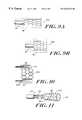
- FIG. 3Ais a side view of an expansion mechanism according to the invention, in a contracted state
- FIG. 3Bis a side view of the expansion mechanism of FIG. 3A in an expanded state
- FIG. 4is a partially cut-away, side view of another non-occluding catheter according to the invention.
- FIG. 5is a partial view of a sheath and a plurality of distribution elements encased therein;
- FIG. 6Ais a cross-sectional view of an energy distributor in a contracted state
- FIG. 6Bis a cross-sectional view of an energy distributor in an expanded state
- FIG. 7Ais a side view of another expansion mechanism in a contracted state
- FIG. 7Bis a side view of the mechanism of FIG. 7A in an expanded state
- FIG. 8Ais a partially, cut-away perspective view of another non-occluding catheter according to the invention in a contracted state
- FIG. 8Bis a similar perspective view of the catheter of FIG. 8A in an expanded state
- FIG. 9Ais a side view of another expander in a contracted state
- FIG. 9Bis a side view of the expander of FIG. 9A in an expanded state
- FIG. 10is a cross-sectional view of an expander in an expanded state together with a surrounding distributor.
- FIG. 11is a cross-sectional view of fluid flow in a non-occluding catheter according to the invention.
- FIG. 1shows one embodiment of the non-occluding catheter 10 of the invention.
- the non-occluding cathetergenerally comprises a hollow instrument body 12 with at least one lumen 14 .
- a sheath casing 16is disposed, within which is a distributor 18 that, optionally, receives energy from an energy source and transmits the energy to a target region in a vessel wall when the expansion mechanism 20 , connected to the distributor 18 expands to bring the distributor into close proximity with the vessel wall.
- the distributor 18can also deliver energy by cooling the site.
- the waveguideserves to connect the distributor 18 with a cryogenic energy source.
- the expansion mechanism 20also creates at least one fluid flow passage 22 that allows unobstructed continuous fluid flow 24 .
- FIG. 2shows a cross-sectional view of a non-occluding catheter of FIG. 1 illustrating the relative positions of the distributor 18 , the expansion mechanism 20 , and the fluid inlet 22 , as well as the sheath casing 16 .
- FIGS. 3A and 3Bare side views of an expansion mechanism 20 A, in a contracted state and expanded state, respectively.
- FIG. 4is a partially cut-away view of another non-occluding catheter 10 A, having an elongated hollow tube 12 , a sheath 16 and a waveguide 26 .
- the waveguideis joined to a distributor 18 that is formed as a branched energy distribution structure 28 within the sheath 16 .
- the distribution array 28 and sheath 16are expandable to bring the diffuser into close proximity with the vessel wall while creating at least one fluid passageway 22 through the distributor 18 .
- FIG. 5is a cross-sectional view of a plurality of light distributing diffusers 30 , surrounded by a sheath casing 16 . Each diffuser receives energy transmitted from an energy source via the waveguide 26 .
- FIGS. 6A and 6Bare cross-sectional views of the plurality of diffusers 30 , within a sheath casing 16 , surrounding the expansion mechanism 20 , in the contracted state and expanded state, respectively.
- FIGS. 7A and 7Bare side views of an alternative expansion mechanism 20 B in a contracted state and an expanded state, respectively.
- expansion of cage wires 32can be induced by retraction of a control pull wire 34 .
- FIGS. 8A and 8Bare partially cut away side views of the expansion mechanism 20 B, within a sheath casing 16 in a contracted state, and an expanded state, respectively.
- the expansion mechanism 20 Bcreates a fluid passageway 22 that permits fluid 24 , to pass through the catheter.
- FIGS. 9A and 9Bare side views of a shape memory expansion mechanism 20 C, connected to a catheter body 12 and being surrounded by the distributor 18 (shown in phantom), in a contracted state and an expanded state, respectively.
- Various shape memory materialscan be employed in the present invention.
- shape memory devicessee, for example, U.S. Pat. Nos. 4,631,094; 5,540,712 and 5,573,508, incorporated herein by reference.
- FIG. 10is a cross-sectional side view of one embodiment of the invention, with an expansion mechanism 20 C, surrounded by a plurality of diffusers 30 , within a sheath casing 16 .
- FIG. 11is a cross-sectional view of the fluid flow 24 , through the fluid inlet 22 , of another non-occluding catheter 10 C according to the invention.
- FIG. 11also illustrates an additional feature of the invention that facilitates flushing of the region between the distributor and the target site.
- Introduction of a flushing mediummay be desirable, for example, to clean blood.
- the embodiment 10 C of FIG. 11provides one or more fluid conduits 42 and at least one port 44 to release fluids at a site.
- Various devices and techniques for intralumenal irrigation or blood flushingare known. See, for examples, U.S. Pat. Nos. 5,833,682; 5,964,751 and 5,876,426, herein incorporated by reference.
- the catheteris first introduced into the lumen of the vessel at a position adjacent to the target region, e.g. an aneurysm, an atherosclerotic plaque, a stenotic lesion, and the like.
- the expansion mechanism 20 , 20 A, 20 B or 20 Cis activated which causes the distributor 18 , to come into close proximity with the wall of the lumen.
- the distributor elementscan be formed of a thin-walled, tube-like flexible material.
- the distributorcan be made of Teflon® P.F.A. materials (polytetrafluoroethylene polymers with perfluoroalpoxy side chains); Teflon® PTFE (polytetrafluoroethylene) and other fluoropolymers.
- the sheath 16can be formed of a low-friction, flexible material, e.g., F.E.P., however polyurethane, silicone, polyethylene, or other similar materials may be substituted for PTFE, C-flex, a styrene ethylene butylene styrene block copolymer, and can be simultaneously stretched and slipped over and around the diffuser.
- a low-friction, flexible materiale.g., F.E.P.
- polyurethane, silicone, polyethylene, or other similar materialsmay be substituted for PTFE, C-flex, a styrene ethylene butylene styrene block copolymer, and can be simultaneously stretched and slipped over and around the diffuser.
- the distributoris a light diffuser comprising one or more light delivery tubes.
- the light diffusercan have light scattering material which directs light to the walls of the light diffuser.
- a scattering materialinclude, but are not limited to, silicone, epoxy or other polymeric material, or suitable liquid such as water or deuterium oxide solution containing colloidal scatter particles.
- individual light scattering particlesmay also be included in the light scattering material, such as silica, alumina, and titania or mixtures thereof.
- the light scattering materialis coated on the inside wall of the light diffuser.
- the inventioncan be practiced without the need for an external energy source or waveguide by deploying one or more sources of radiation within the distributor.
- Such radiation sourcescan be, for example, liquid radioisotopes or solid radiative pellets.
- the arrangement of the distribution elementsis such that the distributor can expand and contract in response to the expansion mechanism.
- a single tubecan be arranged, for example, in a helical configuration surrounding the expansion mechanism.
- a branched networkcan be contracted.
- the energy distributorcomprises a plurality of heat conductive tubes arranged around the expansion mechanism.
- the distributorcan be a large area resistive heater including one or more heating elements connected to an electric current source.
- the energy sourcecan be any source required to be delivered to a target site.
- Examples of an energy sourceinclude, but are not limited to, light and heat.
- the sourcecan be a UV light source having a wavelength ranging from about 200 to about 400 nanometers, preferably from about 240 to about 370 nanometers.
- the radiationcan be provided from a variety of sources; including non-coherent UV light sources (e.g., a LF excimer laser operating at 248 nanometers or an Argon ion laser at 257 or 275 nanometers.
- a therapeutic agentcan be used in lieu of, or in combination with, an energy source to treat a target region.
- the therapeutic agentcan be delivered through the distributor topically.
- Therapeutic agentscan also be coated to the exterior surface of the diffuser. In an expanded state, the diffuser would come into close contact with the vessel wall and deposit the therapeutic agent at the target region.
- the expansion mechanismcan be any mechanism that pushes the diffuser against the vessel wall while permitting the flow of fluid (e.g., blood, serum, plasma) through the vessel.
- the expansion mechanismprovides structural support in the diffuser.
- the expansion mechanismtraverses a major portion of the diffuser to provide structural support and to maintain the shape of the diffuser when inserted in the vessel.
- the expansion mechanismis a flexible spring.
- the springcan be formed from a continuous piece of fine gauge stainless steel spring wire that, if opened out, would appear in the shape of a zig-zag with multiple elbows. (See, e.g., U.S. Pat. No. 5,855,565 issued to Bar-Cohen et al.) These elbows may be simple arches or recurved arches. The advantage of simple arches is that the spring expands more evenly. The advantage of the recurved arches is that they collapse more readily and are more durable.
- the springmay be constructed out of inert metals such as titanium, or a plastic. When expanded, the spring can be circular in shape when viewed from above, and may have a diameter smaller than the diameter of the blood vessel lumen when in a contracted state.
- the expansion mechanismis a coil that is inherently flexible and returns to its original shape after being manipulated during insertion into the vessel.
- a braid, mesh, or other rigid structuressuch as a tube or cylinder may also be used.
- the manufacture of the coilmay be achieved by embedding the coil into an elastomer or other fluid impermeable flexible material.
- the elastomercan be drawn over a wire and subsequently shrunk onto the coil, i.e., by heat treatment.
- the coilcan be formed from several materials, for example, stainless steel, tungsten, aluminum and the like. Additionally, a synthetic coil can be formed from Kevlar and like materials. When expanded, the coil can be helical in shape, and may have a diameter less than the diameter of the blood vessel lumen when in a contracted state.
- the expandermay be self-expanding or, may be activated to expand using a control mechanism, for example, a cable mechanism which causes expansion and contraction of an expander, as described in U.S. Pat. No. 5,855,565 issued to Bar-Cohen et al.
- the expansion mechanismcan also be one that is expandable out of and retractable back into the elongated hollow instrument.
- the expansion mechanismcan be radially compressed into a pre-loaded condition within the hollow instrument of the catheter prior to expansion within the vessel lumen. Once proper positioning and alignment of the catheter is achieved, the expansion mechanism is released to allow it to expand radially outward and conform with the interior surface of the vessel.
- various configurations of flexible springs and/or coilsare employed as the basic expansion mechanism.
- the coilsgenerally are provided with a loose or compliant cover, for example, a fluid-impermeable, flexible elastomer material.
- the coil diameteris controlled by the application of a force to a thread, thin wire or the like, which force in turn alters a natural state of the coil to a contracted state.
- the expansion mechanismscan comprise springs or coils designed to exert radially outward with a force of approximately 240 to 340 grams into conforming fixed engagement with the interior surface of the target region.
- the wire of the springmay be coated with titanium oxide to improve biocompatibility and reduce the incidence of allergic reaction.
- the catheterdoes not occlude the flow of blood, but enables blood to pass through the catheter during the entire procedure.
- the non-occluding catheterdoes not need to rely upon inflation for expansion, but rather can be mechanically expandable in a way that enables precise control of the amount and speed of expansion during use. As the non-occluding catheter does not restrict the flow of fluid (e.g., blood) at anytime, more time is available to treat the target region compared to conventional techniques.
- the non-occluding catheter of the inventionis of a size to fit comfortably within an arterial vessel, and is of an overall length and diameter usually in accord with a vessel and permits the flow of blood.
- the non-occluding catheteris flexible enough to be placed within a moving vessel without damaging the vessel or the surrounding tissues, and is structurally durable enough to maintain a shape permitting the flow of blood.
- the non-occluding catheter of the inventioncan be used for a variety of therapeutic purposes.
- One applicationis photodynamic therapy (PDT), a form of light activated chemotherapy.
- PDTphotodynamic therapy
- photosensitive agentsare delivered to the target region.
- the target regioncan be irradiated with an appropriate wavelength using the non-occluding catheter of the invention.
- a photochemical reactionoccurs that yields radicals (usually singlet oxygen) which causes metabolic changes in the cell.
- One advantage of the present inventionis that it permits PDT at treatment sites without compromising blood flow at these sites.
- the inventionalso encompasses the use of heat based therapy.
- heat-based therapycan be used to heat lesions, such as atherosclerotic plaques in a vessel. As the fluid in the vessel is not occluded during treatment, the heat therapy can be applied for longer periods of time.
- the non-occluding catheter of the present inventioncan also be used to deliver drugs or therapeutic agents to the walls of a lumen or vessel.
- drugs or agents which can be deliveredinclude substances which inhibit platelet deposition and thrombus formation, or promote thrombolysis and thrombus dissolution, such as plasmin, tissue plasminogen activator (tPA), single chain prourokinase (scuPA), prostaglandins, cyclooxygenase inhibitors, phosphodiesterase inhibitors, thromboxane synthetase inhibitors; antagonists of glycoprotein receptors including (GP) Ib, GP IIb/IIIa, antagonists of collagen receptors, and antagonists of platelet thrombin receptors.
- tPAtissue plasminogen activator
- scuPAsingle chain prourokinase
- prostaglandinsprostaglandins
- cyclooxygenase inhibitorscyclooxygenase inhibitors
- antiproliferativeswhich can be delivered by the non-occluding catheter include dexamethasone, growth factor, a growth factor inhibitor, growth factor receptor antagonist, transcriptional repressor, translational repressor, antisense DNA, antisense RNA, replication inhibitor, inhibitory antibodies, antibodies directed against growth factors or their receptors, bifunctional molecules comprising a growth factor and a cytotoxin, bifunctional molecules comprising an antibody and a cytotoxin.
- the drugs or therapeutic agents delivered by the non-occluding cathetercan also be vasodilators, such as nitroglycerin, nitroprusside or other nitric oxide liberators.
- the vasodilatorcan also include other suitable vasoactive agents such as beta receptor blocking drugs, inhibitors of intracellular calcium transport, prostaglandins, thromboxane antagonists, and the like.
- the non-occluding cathetercan also be used for cardiovascular applications which include the delivery of medical grade cyanoacrylides for the treatment of aneurysms, arterial venous fistulas, or carotid cavernous fistulas.
Landscapes
- Health & Medical Sciences (AREA)
- Surgery (AREA)
- Physics & Mathematics (AREA)
- Life Sciences & Earth Sciences (AREA)
- Engineering & Computer Science (AREA)
- Medical Informatics (AREA)
- Nuclear Medicine, Radiotherapy & Molecular Imaging (AREA)
- Electromagnetism (AREA)
- Optics & Photonics (AREA)
- Biomedical Technology (AREA)
- Heart & Thoracic Surgery (AREA)
- Otolaryngology (AREA)
- Molecular Biology (AREA)
- Animal Behavior & Ethology (AREA)
- General Health & Medical Sciences (AREA)
- Public Health (AREA)
- Veterinary Medicine (AREA)
- Infusion, Injection, And Reservoir Apparatuses (AREA)
Abstract
Description
Claims (55)
Priority Applications (1)
| Application Number | Priority Date | Filing Date | Title |
|---|---|---|---|
| US09/450,312US6263236B1 (en) | 1999-11-29 | 1999-11-29 | Non-occlusive expandable catheter |
Applications Claiming Priority (1)
| Application Number | Priority Date | Filing Date | Title |
|---|---|---|---|
| US09/450,312US6263236B1 (en) | 1999-11-29 | 1999-11-29 | Non-occlusive expandable catheter |
Publications (1)
| Publication Number | Publication Date |
|---|---|
| US6263236B1true US6263236B1 (en) | 2001-07-17 |
Family
ID=23787594
Family Applications (1)
| Application Number | Title | Priority Date | Filing Date |
|---|---|---|---|
| US09/450,312Expired - Fee RelatedUS6263236B1 (en) | 1999-11-29 | 1999-11-29 | Non-occlusive expandable catheter |
Country Status (1)
| Country | Link |
|---|---|
| US (1) | US6263236B1 (en) |
Cited By (80)
| Publication number | Priority date | Publication date | Assignee | Title |
|---|---|---|---|---|
| US6719778B1 (en)* | 2000-03-24 | 2004-04-13 | Endovascular Technologies, Inc. | Methods for treatment of aneurysms |
| US20040082965A1 (en)* | 1996-06-14 | 2004-04-29 | Beckham James P. | Medical balloon |
| US20050090845A1 (en)* | 2000-02-18 | 2005-04-28 | Boyd Stephen W. | Methods and devices for removing material from a vascular site |
| US20050123702A1 (en)* | 2003-12-03 | 2005-06-09 | Jim Beckham | Non-compliant medical balloon having a longitudinal fiber layer |
| US20050288655A1 (en)* | 2004-06-29 | 2005-12-29 | Howard Root | Laser fiber for endovenous therapy having a shielded distal tip |
| US20060058815A1 (en)* | 2004-09-16 | 2006-03-16 | Mickley Timothy J | Expandable multi-port therapeutic delivery system, device, and method |
| US20060217653A1 (en)* | 2005-03-24 | 2006-09-28 | Medtronic Vascular, Inc. | Catheter-based, dual coil photopolymerization system |
| US20070016243A1 (en)* | 2005-06-28 | 2007-01-18 | Venkatesh Ramaiah | Non-occlusive, retrievable dilation system |
| US20070016133A1 (en)* | 2005-07-05 | 2007-01-18 | Futurematrix Interventional, Inc. | Rapid exchange balloon dilation catheter having reinforced multi-lumen distal portion |
| WO2007048259A1 (en)* | 2005-10-28 | 2007-05-03 | Carag Ag | Intravascular device |
| US20070179486A1 (en)* | 2004-06-29 | 2007-08-02 | Jeff Welch | Laser fiber for endovenous therapy having a shielded distal tip |
| US20070219490A1 (en)* | 2004-10-15 | 2007-09-20 | Futuremed Interventional, Inc. | Non-compliant medical balloon having an integral non-woven fabric layer |
| US20080058856A1 (en)* | 2005-06-28 | 2008-03-06 | Venkatesh Ramaiah | Non-occluding dilation device |
| US20080065125A1 (en)* | 2000-12-20 | 2008-03-13 | Foxhollow Technologies, Inc. | High capacity debulking catheter with distal driven cutting wheel |
| US20080097251A1 (en)* | 2006-06-15 | 2008-04-24 | Eilaz Babaev | Method and apparatus for treating vascular obstructions |
| US20080114439A1 (en)* | 2005-06-28 | 2008-05-15 | Venkatesh Ramaiah | Non-occluding dilation device |
| US20080281284A1 (en)* | 2007-05-08 | 2008-11-13 | Garfield Michael H | Fluid collection system |
| US20080287911A1 (en)* | 2007-05-16 | 2008-11-20 | Abbott Cardiovascular Systems Inc. | Catheter with laminar flow drug delivery properties |
| US20090076448A1 (en)* | 2007-09-17 | 2009-03-19 | Consigny Paul M | Methods and devices for eluting agents to a vessel |
| US20090149700A1 (en)* | 2007-11-02 | 2009-06-11 | Ruben Garcia | Method and apparatus for pubic sling insertion |
| US20090171277A1 (en)* | 2005-06-22 | 2009-07-02 | Futurematrix Interventional, Inc. | Balloon dilation catheter having transition from coaxial lumens to non-coaxial multiple lumens |
| US20090264875A1 (en)* | 2002-07-10 | 2009-10-22 | Appling William M | Method of Treating a Blood Vessel with an Optical Fiber Having a Spacer |
| US20090306590A1 (en)* | 2005-06-07 | 2009-12-10 | Staskin David R | Injection guidance system and method |
| US20090326314A1 (en)* | 2005-12-16 | 2009-12-31 | Cutrer L Michael | Brachytherapy apparatus for asymmetrical body cavities |
| US20100106240A1 (en)* | 2008-10-20 | 2010-04-29 | IMDS, Inc. | Systems and Methods for Aneurysm Treatment and Vessel Occlusion |
| EP2166921A4 (en)* | 2007-06-15 | 2010-07-07 | Max Endoscopy Inc | Flexible infrared delivery apparatus and method |
| US20100318029A1 (en)* | 2009-06-12 | 2010-12-16 | Pepper Lanny R | Semi-compliant medical balloon |
| US7862497B2 (en) | 2006-04-21 | 2011-01-04 | Portola Medical, Inc. | Brachytherapy device having seed tubes with individually-settable tissue spacings |
| US7914487B2 (en) | 2004-10-15 | 2011-03-29 | Futurematrix Interventional, Inc. | Non-compliant medical balloon having braided or knitted reinforcement |
| US20110082490A1 (en)* | 2009-05-15 | 2011-04-07 | Lemaitre Vascular, Inc. | Non-Occlusive Dilation Devices |
| US8002741B2 (en) | 2004-10-15 | 2011-08-23 | Bard Peripheral Vascular, Inc. | Non-compliant medical balloon having an integral woven fabric layer |
| US8002744B2 (en) | 2007-08-06 | 2011-08-23 | Bard Peripheral Vascular, Inc | Non-compliant medical balloon |
| US8137256B2 (en) | 2005-12-16 | 2012-03-20 | Portola Medical, Inc. | Brachytherapy apparatus |
| US8192452B2 (en) | 2009-05-14 | 2012-06-05 | Tyco Healthcare Group Lp | Easily cleaned atherectomy catheters and methods of use |
| US8226674B2 (en) | 2000-12-20 | 2012-07-24 | Tyco Healthcare Group Lp | Debulking catheters and methods |
| US8246640B2 (en) | 2003-04-22 | 2012-08-21 | Tyco Healthcare Group Lp | Methods and devices for cutting tissue at a vascular location |
| US8313601B2 (en) | 2007-08-06 | 2012-11-20 | Bard Peripheral Vascular, Inc. | Non-compliant medical balloon |
| US8328829B2 (en) | 1999-08-19 | 2012-12-11 | Covidien Lp | High capacity debulking catheter with razor edge cutting window |
| US8353868B2 (en) | 2004-10-15 | 2013-01-15 | Bard Peripheral Vascular, Inc. | Medical balloon having strengthening rods |
| US8414604B2 (en) | 2008-10-13 | 2013-04-09 | Covidien Lp | Devices and methods for manipulating a catheter shaft |
| US8496677B2 (en) | 2009-12-02 | 2013-07-30 | Covidien Lp | Methods and devices for cutting tissue |
| US8597240B2 (en) | 2011-02-02 | 2013-12-03 | Futurematrix Interventional, Inc. | Coaxial catheter shaft having balloon attachment feature with axial fluid path |
| US8597315B2 (en) | 1999-08-19 | 2013-12-03 | Covidien Lp | Atherectomy catheter with first and second imaging devices |
| US8728110B2 (en) | 2009-01-16 | 2014-05-20 | Bard Peripheral Vascular, Inc. | Balloon dilation catheter shaft having end transition |
| US8784440B2 (en) | 2008-02-25 | 2014-07-22 | Covidien Lp | Methods and devices for cutting tissue |
| US8808186B2 (en) | 2010-11-11 | 2014-08-19 | Covidien Lp | Flexible debulking catheters with imaging and methods of use and manufacture |
| US8814899B2 (en) | 2009-02-23 | 2014-08-26 | Futurematrix Interventional, Inc. | Balloon catheter pressure relief valve |
| US8920450B2 (en) | 2010-10-28 | 2014-12-30 | Covidien Lp | Material removal device and method of use |
| US8992717B2 (en) | 2011-09-01 | 2015-03-31 | Covidien Lp | Catheter with helical drive shaft and methods of manufacture |
| US8998937B2 (en) | 1999-08-19 | 2015-04-07 | Covidien Lp | Methods and devices for cutting tissue |
| US9028512B2 (en) | 2009-12-11 | 2015-05-12 | Covidien Lp | Material removal device having improved material capture efficiency and methods of use |
| US9119662B2 (en) | 2010-06-14 | 2015-09-01 | Covidien Lp | Material removal device and method of use |
| US9211391B2 (en) | 2009-09-24 | 2015-12-15 | Bard Peripheral Vascular, Inc. | Balloon with variable pitch reinforcing fibers |
| US9259559B2 (en) | 2009-02-23 | 2016-02-16 | Futurematrix Interventional, Inc. | Balloon catheter pressure relief valve |
| US9532844B2 (en) | 2012-09-13 | 2017-01-03 | Covidien Lp | Cleaning device for medical instrument and method of use |
| EP3019238A4 (en)* | 2013-07-10 | 2017-03-29 | Oxys AG | Devices and methods for delivery of therapeutic energy |
| US9687266B2 (en) | 2009-04-29 | 2017-06-27 | Covidien Lp | Methods and devices for cutting and abrading tissue |
| JP2017113556A (en)* | 2015-12-22 | 2017-06-29 | デピュイ・シンセス・プロダクツ・インコーポレイテッド | Efficient delivery of phototherapy using optical fiber |
| US9782562B2 (en) | 2002-04-04 | 2017-10-10 | Angiodynamics, Inc. | Venous insufficiency treatment method |
| US9801647B2 (en) | 2006-05-26 | 2017-10-31 | Covidien Lp | Catheter including cutting element and energy emitting element |
| US9814513B2 (en) | 2011-06-30 | 2017-11-14 | Angiodynamics, Inc. | Endovascular plasma treatment device and method of use |
| US9943329B2 (en) | 2012-11-08 | 2018-04-17 | Covidien Lp | Tissue-removing catheter with rotatable cutter |
| US10105154B1 (en) | 2017-11-09 | 2018-10-23 | Pebble Hill Partners, Llc | Basket for a catheter device |
| US10213224B2 (en) | 2014-06-27 | 2019-02-26 | Covidien Lp | Cleaning device for catheter and catheter including the same |
| US10238453B2 (en) | 2002-07-10 | 2019-03-26 | Angiodynamics, Inc. | Method of making an endovascular laser treatment device for causing closure of a blood vessel |
| US10245417B2 (en) | 2013-10-16 | 2019-04-02 | Ra Medical Systems, Inc. | Package for extended shelf life of liquid core catheters |
| US10292721B2 (en) | 2015-07-20 | 2019-05-21 | Covidien Lp | Tissue-removing catheter including movable distal tip |
| US10314664B2 (en) | 2015-10-07 | 2019-06-11 | Covidien Lp | Tissue-removing catheter and tissue-removing element with depth stop |
| US10314667B2 (en) | 2015-03-25 | 2019-06-11 | Covidien Lp | Cleaning device for cleaning medical instrument |
| US10555772B2 (en) | 2015-11-23 | 2020-02-11 | Ra Medical Systems, Inc. | Laser ablation catheters having expanded distal tip windows for efficient tissue ablation |
| US20200054867A1 (en)* | 2018-08-14 | 2020-02-20 | NXT Biomedical | System And Method For Treatment Via Bodily Drainage Or Injection |
| US11123458B2 (en) | 2011-10-14 | 2021-09-21 | Ra Medical Systems, Inc. | Small flexible liquid core catheter for laser ablation in body lumens and methods for use |
| US11147616B2 (en) | 2018-03-22 | 2021-10-19 | Ra Medical Systems, Inc. | Liquid filled ablation catheter with overjacket |
| US11179169B2 (en)* | 2016-11-04 | 2021-11-23 | Les Solutions Medicales Soundbite Inc. | Device for delivering mechanical waves through a balloon catheter |
| US11576724B2 (en) | 2011-02-24 | 2023-02-14 | Eximo Medical Ltd. | Hybrid catheter for vascular intervention |
| US11684420B2 (en) | 2016-05-05 | 2023-06-27 | Eximo Medical Ltd. | Apparatus and methods for resecting and/or ablating an undesired tissue |
| EP4275635A1 (en)* | 2022-05-12 | 2023-11-15 | Micro Energy Medical Technology Co., Ltd | Laser ablation catheter |
| CN117224856A (en)* | 2023-10-27 | 2023-12-15 | 丹阳慧创医疗设备有限公司 | Phototherapy device |
| US12038322B2 (en) | 2022-06-21 | 2024-07-16 | Eximo Medical Ltd. | Devices and methods for testing ablation systems |
| US12376904B1 (en) | 2020-09-08 | 2025-08-05 | Angiodynamics, Inc. | Dynamic laser stabilization and calibration system |
Citations (19)
| Publication number | Priority date | Publication date | Assignee | Title |
|---|---|---|---|---|
| US4878492A (en) | 1987-10-08 | 1989-11-07 | C. R. Bard, Inc. | Laser balloon catheter |
| US5074871A (en) | 1989-12-07 | 1991-12-24 | Evi Corporation | Catheter atherotome |
| US5188602A (en) | 1990-07-12 | 1993-02-23 | Interventional Thermodynamics, Inc. | Method and device for delivering heat to hollow body organs |
| US5188635A (en) | 1988-02-08 | 1993-02-23 | Wolfgang Radtke | Catheter for percutaneous surgery of blood vessels and organs using radiant energy |
| USRE34544E (en) | 1982-11-23 | 1994-02-15 | The Beth Israel Hospital Association | Method of treatment of artherosclerosis and balloon catheter the same |
| US5366443A (en)* | 1992-01-07 | 1994-11-22 | Thapliyal And Eggers Partners | Method and apparatus for advancing catheters through occluded body lumens |
| US5620438A (en) | 1995-04-20 | 1997-04-15 | Angiomedics Ii Incorporated | Method and apparatus for treating vascular tissue following angioplasty to minimize restenosis |
| US5632767A (en) | 1994-09-09 | 1997-05-27 | Rare Earth Medical, Inc. | Loop diffusers for diffusion of optical radiation |
| US5637877A (en) | 1995-06-06 | 1997-06-10 | Rare Earth Medical, Inc. | Ultraviolet sterilization of instrument lumens |
| US5643253A (en) | 1995-06-06 | 1997-07-01 | Rare Earth Medical, Inc. | Phototherapy apparatus with integral stopper device |
| US5649978A (en) | 1993-05-11 | 1997-07-22 | Target Therapeutics, Inc. | Temporary inflatable intravascular prosthesis |
| US5700243A (en) | 1992-10-30 | 1997-12-23 | Pdt Systems, Inc. | Balloon perfusion catheter |
| US5797868A (en) | 1996-07-25 | 1998-08-25 | Cordis Corporation | Photodynamic therapy balloon catheter |
| US5824005A (en) | 1995-08-22 | 1998-10-20 | Board Of Regents, The University Of Texas System | Maneuverable electrophysiology catheter for percutaneous or intraoperative ablation of cardiac arrhythmias |
| US5833682A (en) | 1996-08-26 | 1998-11-10 | Illumenex Corporation | Light delivery system with blood flushing capability |
| US5855565A (en) | 1997-02-21 | 1999-01-05 | Bar-Cohen; Yaniv | Cardiovascular mechanically expanding catheter |
| US5876426A (en) | 1996-06-13 | 1999-03-02 | Scimed Life Systems, Inc. | System and method of providing a blood-free interface for intravascular light delivery |
| US5964751A (en) | 1996-08-26 | 1999-10-12 | Illumenex Corporation | Light delivery system with blood flushing capability |
| US6004269A (en)* | 1993-07-01 | 1999-12-21 | Boston Scientific Corporation | Catheters for imaging, sensing electrical potentials, and ablating tissue |
- 1999
- 1999-11-29USUS09/450,312patent/US6263236B1/ennot_activeExpired - Fee Related
Patent Citations (19)
| Publication number | Priority date | Publication date | Assignee | Title |
|---|---|---|---|---|
| USRE34544E (en) | 1982-11-23 | 1994-02-15 | The Beth Israel Hospital Association | Method of treatment of artherosclerosis and balloon catheter the same |
| US4878492A (en) | 1987-10-08 | 1989-11-07 | C. R. Bard, Inc. | Laser balloon catheter |
| US5188635A (en) | 1988-02-08 | 1993-02-23 | Wolfgang Radtke | Catheter for percutaneous surgery of blood vessels and organs using radiant energy |
| US5074871A (en) | 1989-12-07 | 1991-12-24 | Evi Corporation | Catheter atherotome |
| US5188602A (en) | 1990-07-12 | 1993-02-23 | Interventional Thermodynamics, Inc. | Method and device for delivering heat to hollow body organs |
| US5366443A (en)* | 1992-01-07 | 1994-11-22 | Thapliyal And Eggers Partners | Method and apparatus for advancing catheters through occluded body lumens |
| US5700243A (en) | 1992-10-30 | 1997-12-23 | Pdt Systems, Inc. | Balloon perfusion catheter |
| US5649978A (en) | 1993-05-11 | 1997-07-22 | Target Therapeutics, Inc. | Temporary inflatable intravascular prosthesis |
| US6004269A (en)* | 1993-07-01 | 1999-12-21 | Boston Scientific Corporation | Catheters for imaging, sensing electrical potentials, and ablating tissue |
| US5632767A (en) | 1994-09-09 | 1997-05-27 | Rare Earth Medical, Inc. | Loop diffusers for diffusion of optical radiation |
| US5620438A (en) | 1995-04-20 | 1997-04-15 | Angiomedics Ii Incorporated | Method and apparatus for treating vascular tissue following angioplasty to minimize restenosis |
| US5637877A (en) | 1995-06-06 | 1997-06-10 | Rare Earth Medical, Inc. | Ultraviolet sterilization of instrument lumens |
| US5643253A (en) | 1995-06-06 | 1997-07-01 | Rare Earth Medical, Inc. | Phototherapy apparatus with integral stopper device |
| US5824005A (en) | 1995-08-22 | 1998-10-20 | Board Of Regents, The University Of Texas System | Maneuverable electrophysiology catheter for percutaneous or intraoperative ablation of cardiac arrhythmias |
| US5876426A (en) | 1996-06-13 | 1999-03-02 | Scimed Life Systems, Inc. | System and method of providing a blood-free interface for intravascular light delivery |
| US5797868A (en) | 1996-07-25 | 1998-08-25 | Cordis Corporation | Photodynamic therapy balloon catheter |
| US5833682A (en) | 1996-08-26 | 1998-11-10 | Illumenex Corporation | Light delivery system with blood flushing capability |
| US5964751A (en) | 1996-08-26 | 1999-10-12 | Illumenex Corporation | Light delivery system with blood flushing capability |
| US5855565A (en) | 1997-02-21 | 1999-01-05 | Bar-Cohen; Yaniv | Cardiovascular mechanically expanding catheter |
Cited By (166)
| Publication number | Priority date | Publication date | Assignee | Title |
|---|---|---|---|---|
| US20070059466A1 (en)* | 1996-06-14 | 2007-03-15 | C.R.Bard | Medical balloon |
| US20040082965A1 (en)* | 1996-06-14 | 2004-04-29 | Beckham James P. | Medical balloon |
| US20040109964A1 (en)* | 1996-06-14 | 2004-06-10 | Beckham James P. | Medical balloon |
| US20110120629A1 (en)* | 1996-06-14 | 2011-05-26 | Beckham James P | Medical balloon |
| US7927443B2 (en) | 1996-06-14 | 2011-04-19 | Bard Peripheral Vascular, Inc. | Medical balloon |
| US8430846B2 (en)* | 1996-06-14 | 2013-04-30 | Bard Peripheral Vascular, Inc. | Medical balloon |
| US20070093865A1 (en)* | 1996-06-14 | 2007-04-26 | C.R.Bard | Medical balloon |
| US8864704B2 (en) | 1996-06-14 | 2014-10-21 | C.R. Bard, Inc. | Medical balloon |
| US9486237B2 (en) | 1999-08-19 | 2016-11-08 | Covidien Lp | Methods and devices for cutting tissue |
| US8328829B2 (en) | 1999-08-19 | 2012-12-11 | Covidien Lp | High capacity debulking catheter with razor edge cutting window |
| US8911459B2 (en) | 1999-08-19 | 2014-12-16 | Covidien Lp | Debulking catheters and methods |
| US9615850B2 (en) | 1999-08-19 | 2017-04-11 | Covidien Lp | Atherectomy catheter with aligned imager |
| US9788854B2 (en) | 1999-08-19 | 2017-10-17 | Covidien Lp | Debulking catheters and methods |
| US9532799B2 (en) | 1999-08-19 | 2017-01-03 | Covidien Lp | Method and devices for cutting tissue |
| US8998937B2 (en) | 1999-08-19 | 2015-04-07 | Covidien Lp | Methods and devices for cutting tissue |
| US8597315B2 (en) | 1999-08-19 | 2013-12-03 | Covidien Lp | Atherectomy catheter with first and second imaging devices |
| US10022145B2 (en) | 1999-08-19 | 2018-07-17 | Covidien Lp | Methods and devices for cutting tissue |
| US8801745B2 (en)* | 2000-02-18 | 2014-08-12 | Covidien Lp | Methods and devices for removing material from a vascular site |
| US9451978B2 (en) | 2000-02-18 | 2016-09-27 | Covidien Lp | Methods and devices for removing material from a vascular site |
| US20050090845A1 (en)* | 2000-02-18 | 2005-04-28 | Boyd Stephen W. | Methods and devices for removing material from a vascular site |
| US8021404B1 (en) | 2000-03-24 | 2011-09-20 | Endovascular Technologies, Inc. | Methods for treatment of aneurysms |
| US6719778B1 (en)* | 2000-03-24 | 2004-04-13 | Endovascular Technologies, Inc. | Methods for treatment of aneurysms |
| US9241733B2 (en) | 2000-12-20 | 2016-01-26 | Covidien Lp | Debulking catheter |
| US20080065125A1 (en)* | 2000-12-20 | 2008-03-13 | Foxhollow Technologies, Inc. | High capacity debulking catheter with distal driven cutting wheel |
| US8052704B2 (en) | 2000-12-20 | 2011-11-08 | Foxhollow Technologies, Inc. | High capacity debulking catheter with distal driven cutting wheel |
| US8226674B2 (en) | 2000-12-20 | 2012-07-24 | Tyco Healthcare Group Lp | Debulking catheters and methods |
| US8469979B2 (en) | 2000-12-20 | 2013-06-25 | Covidien Lp | High capacity debulking catheter with distal driven cutting wheel |
| US9782562B2 (en) | 2002-04-04 | 2017-10-10 | Angiodynamics, Inc. | Venous insufficiency treatment method |
| US10238453B2 (en) | 2002-07-10 | 2019-03-26 | Angiodynamics, Inc. | Method of making an endovascular laser treatment device for causing closure of a blood vessel |
| EP1539012A4 (en)* | 2002-07-10 | 2010-03-10 | Angiodynamics Inc | Endovascular treatment device having a fiber tip spacer |
| US20090264875A1 (en)* | 2002-07-10 | 2009-10-22 | Appling William M | Method of Treating a Blood Vessel with an Optical Fiber Having a Spacer |
| US8840606B2 (en) | 2002-07-10 | 2014-09-23 | Angiodynamics, Inc. | Method of treating a blood vessel with an optical fiber having a spacer |
| US8425501B2 (en) | 2002-07-10 | 2013-04-23 | Angiodynamics, Inc. | Method of treating a blood vessel with an optical fiber having a spacer |
| US9999438B2 (en) | 2003-04-22 | 2018-06-19 | Covidien Lp | Methods and devices for cutting tissue at a vascular location |
| US8246640B2 (en) | 2003-04-22 | 2012-08-21 | Tyco Healthcare Group Lp | Methods and devices for cutting tissue at a vascular location |
| US8961546B2 (en) | 2003-04-22 | 2015-02-24 | Covidien Lp | Methods and devices for cutting tissue at a vascular location |
| US20050123702A1 (en)* | 2003-12-03 | 2005-06-09 | Jim Beckham | Non-compliant medical balloon having a longitudinal fiber layer |
| US20100179581A1 (en)* | 2003-12-03 | 2010-07-15 | Jim Beckham | Non-Compliant Medical Balloon Having a Longitudinal Fiber Layer |
| US8323242B2 (en) | 2003-12-03 | 2012-12-04 | C.R. Bard, Inc. | Non-compliant medical balloon having a longitudinal fiber layer |
| US20070179486A1 (en)* | 2004-06-29 | 2007-08-02 | Jeff Welch | Laser fiber for endovenous therapy having a shielded distal tip |
| US20050288655A1 (en)* | 2004-06-29 | 2005-12-29 | Howard Root | Laser fiber for endovenous therapy having a shielded distal tip |
| US20060058815A1 (en)* | 2004-09-16 | 2006-03-16 | Mickley Timothy J | Expandable multi-port therapeutic delivery system, device, and method |
| US7470252B2 (en)* | 2004-09-16 | 2008-12-30 | Boston Scientific Scimed, Inc. | Expandable multi-port therapeutic delivery system |
| US8105275B2 (en) | 2004-10-15 | 2012-01-31 | Bard Peripheral Vascular, Inc. | Non-compliant medical balloon having an integral non-woven fabric layer |
| US8221351B2 (en) | 2004-10-15 | 2012-07-17 | Bard Peripheral Vascular, Inc. | Non-compliant medical balloon having an integral non-woven fabric layer |
| US7914487B2 (en) | 2004-10-15 | 2011-03-29 | Futurematrix Interventional, Inc. | Non-compliant medical balloon having braided or knitted reinforcement |
| US8353868B2 (en) | 2004-10-15 | 2013-01-15 | Bard Peripheral Vascular, Inc. | Medical balloon having strengthening rods |
| US7682335B2 (en) | 2004-10-15 | 2010-03-23 | Futurematrix Interventional, Inc. | Non-compliant medical balloon having an integral non-woven fabric layer |
| US8002741B2 (en) | 2004-10-15 | 2011-08-23 | Bard Peripheral Vascular, Inc. | Non-compliant medical balloon having an integral woven fabric layer |
| US7780629B2 (en) | 2004-10-15 | 2010-08-24 | Futurematrix Interventional, Inc. | Non-compliant medical balloon having an integral non-woven fabric layer |
| US20070219490A1 (en)* | 2004-10-15 | 2007-09-20 | Futuremed Interventional, Inc. | Non-compliant medical balloon having an integral non-woven fabric layer |
| US7457661B2 (en)* | 2005-03-24 | 2008-11-25 | Medtronic Vascular, Inc. | Catheter-based, dual coil photopolymerization system |
| US20090018487A1 (en)* | 2005-03-24 | 2009-01-15 | Medtronic Vascular, Inc. | Catheter-Based, Dual Coil Photopolymerization System |
| US20060217653A1 (en)* | 2005-03-24 | 2006-09-28 | Medtronic Vascular, Inc. | Catheter-based, dual coil photopolymerization system |
| US7653432B2 (en) | 2005-03-24 | 2010-01-26 | Medtronic Vascular, Inc. | Catheter-based, dual coil photopolymerization system |
| US8439867B2 (en)* | 2005-06-07 | 2013-05-14 | David R. Staskin | Injection guidance system and method |
| US20090306590A1 (en)* | 2005-06-07 | 2009-12-10 | Staskin David R | Injection guidance system and method |
| US7985235B2 (en) | 2005-06-22 | 2011-07-26 | Bard Peripheral Vascular, Inc. | Balloon dilation catheter having transition from coaxial lumens to non-coaxial multiple lumens |
| US20090171277A1 (en)* | 2005-06-22 | 2009-07-02 | Futurematrix Interventional, Inc. | Balloon dilation catheter having transition from coaxial lumens to non-coaxial multiple lumens |
| US20080058856A1 (en)* | 2005-06-28 | 2008-03-06 | Venkatesh Ramaiah | Non-occluding dilation device |
| US20070016243A1 (en)* | 2005-06-28 | 2007-01-18 | Venkatesh Ramaiah | Non-occlusive, retrievable dilation system |
| US20080114439A1 (en)* | 2005-06-28 | 2008-05-15 | Venkatesh Ramaiah | Non-occluding dilation device |
| US20070016133A1 (en)* | 2005-07-05 | 2007-01-18 | Futurematrix Interventional, Inc. | Rapid exchange balloon dilation catheter having reinforced multi-lumen distal portion |
| US7985236B2 (en) | 2005-07-05 | 2011-07-26 | Bard Peripheral Vascular, Inc. | Rapid exchange balloon dilation catheter having reinforced multi-lumen distal portion |
| US7544201B2 (en) | 2005-07-05 | 2009-06-09 | Futurematrix Interventional, Inc. | Rapid exchange balloon dilation catheter having reinforced multi-lumen distal portion |
| WO2007048259A1 (en)* | 2005-10-28 | 2007-05-03 | Carag Ag | Intravascular device |
| US20090221967A1 (en)* | 2005-10-28 | 2009-09-03 | Carag Ag | Intravascular Device |
| US8226539B2 (en) | 2005-12-16 | 2012-07-24 | Portola Medical, Inc. | Brachytherapy apparatus for asymmetrical body cavities |
| US8137256B2 (en) | 2005-12-16 | 2012-03-20 | Portola Medical, Inc. | Brachytherapy apparatus |
| US20090326314A1 (en)* | 2005-12-16 | 2009-12-31 | Cutrer L Michael | Brachytherapy apparatus for asymmetrical body cavities |
| US7862497B2 (en) | 2006-04-21 | 2011-01-04 | Portola Medical, Inc. | Brachytherapy device having seed tubes with individually-settable tissue spacings |
| US9801647B2 (en) | 2006-05-26 | 2017-10-31 | Covidien Lp | Catheter including cutting element and energy emitting element |
| US11666355B2 (en) | 2006-05-26 | 2023-06-06 | Covidien Lp | Catheter including cutting element and energy emitting element |
| US10588653B2 (en) | 2006-05-26 | 2020-03-17 | Covidien Lp | Catheter including cutting element and energy emitting element |
| US20080097251A1 (en)* | 2006-06-15 | 2008-04-24 | Eilaz Babaev | Method and apparatus for treating vascular obstructions |
| US20080281284A1 (en)* | 2007-05-08 | 2008-11-13 | Garfield Michael H | Fluid collection system |
| US8641666B2 (en)* | 2007-05-16 | 2014-02-04 | Abbott Cardiovascular Systems Inc. | Catheter with laminar flow drug delivery properties |
| US20080287911A1 (en)* | 2007-05-16 | 2008-11-20 | Abbott Cardiovascular Systems Inc. | Catheter with laminar flow drug delivery properties |
| EP2166921A4 (en)* | 2007-06-15 | 2010-07-07 | Max Endoscopy Inc | Flexible infrared delivery apparatus and method |
| US8313601B2 (en) | 2007-08-06 | 2012-11-20 | Bard Peripheral Vascular, Inc. | Non-compliant medical balloon |
| US8236221B2 (en) | 2007-08-06 | 2012-08-07 | Bard Peripheral Vascular, Inc. | Non-compliant medical balloon |
| US8002744B2 (en) | 2007-08-06 | 2011-08-23 | Bard Peripheral Vascular, Inc | Non-compliant medical balloon |
| US8556849B2 (en) | 2007-09-17 | 2013-10-15 | Abbott Cardiovascular Systems Inc. | Methods and devices for eluting agents to a vessel |
| US20090076448A1 (en)* | 2007-09-17 | 2009-03-19 | Consigny Paul M | Methods and devices for eluting agents to a vessel |
| WO2009038612A1 (en)* | 2007-09-17 | 2009-03-26 | Abbott Cardiovascular Systems Inc. | Methods and devices for eluting agents to a vessel |
| US9636486B2 (en) | 2007-09-17 | 2017-05-02 | Abbott Cardiovascular Systems Inc. | Methods and devices for eluting agents to a vessel |
| US8100855B2 (en) | 2007-09-17 | 2012-01-24 | Abbott Cardiovascular Systems, Inc. | Methods and devices for eluting agents to a vessel |
| US9216027B2 (en) | 2007-09-17 | 2015-12-22 | Abbott Cardiovascular Systems Inc. | Methods and devices for eluting agents to a vessel |
| US20090149700A1 (en)* | 2007-11-02 | 2009-06-11 | Ruben Garcia | Method and apparatus for pubic sling insertion |
| US8784440B2 (en) | 2008-02-25 | 2014-07-22 | Covidien Lp | Methods and devices for cutting tissue |
| US10219824B2 (en) | 2008-02-25 | 2019-03-05 | Covidien Lp | Methods and devices for cutting tissue |
| US9445834B2 (en) | 2008-02-25 | 2016-09-20 | Covidien Lp | Methods and devices for cutting tissue |
| US9192406B2 (en) | 2008-10-13 | 2015-11-24 | Covidien Lp | Method for manipulating catheter shaft |
| US8414604B2 (en) | 2008-10-13 | 2013-04-09 | Covidien Lp | Devices and methods for manipulating a catheter shaft |
| US10507037B2 (en) | 2008-10-13 | 2019-12-17 | Covidien Lp | Method for manipulating catheter shaft |
| US8470013B2 (en) | 2008-10-20 | 2013-06-25 | Imds Corporation | Systems and methods for aneurysm treatment and vessel occlusion |
| US20100106240A1 (en)* | 2008-10-20 | 2010-04-29 | IMDS, Inc. | Systems and Methods for Aneurysm Treatment and Vessel Occlusion |
| US8728110B2 (en) | 2009-01-16 | 2014-05-20 | Bard Peripheral Vascular, Inc. | Balloon dilation catheter shaft having end transition |
| US9259559B2 (en) | 2009-02-23 | 2016-02-16 | Futurematrix Interventional, Inc. | Balloon catheter pressure relief valve |
| US8814899B2 (en) | 2009-02-23 | 2014-08-26 | Futurematrix Interventional, Inc. | Balloon catheter pressure relief valve |
| US10555753B2 (en) | 2009-04-29 | 2020-02-11 | Covidien Lp | Methods and devices for cutting and abrading tissue |
| US9687266B2 (en) | 2009-04-29 | 2017-06-27 | Covidien Lp | Methods and devices for cutting and abrading tissue |
| US8192452B2 (en) | 2009-05-14 | 2012-06-05 | Tyco Healthcare Group Lp | Easily cleaned atherectomy catheters and methods of use |
| US8574249B2 (en) | 2009-05-14 | 2013-11-05 | Covidien Lp | Easily cleaned atherectomy catheters and methods of use |
| US9220530B2 (en) | 2009-05-14 | 2015-12-29 | Covidien Lp | Easily cleaned atherectomy catheters and methods of use |
| US8784467B2 (en) | 2009-05-15 | 2014-07-22 | Lemaitre Vascular, Inc. | Non-occlusive dilation devices |
| US20110082490A1 (en)* | 2009-05-15 | 2011-04-07 | Lemaitre Vascular, Inc. | Non-Occlusive Dilation Devices |
| US9802027B2 (en)* | 2009-06-12 | 2017-10-31 | Bard Peripheral Vascular, Inc. | Semi-compliant medical balloon |
| US8900215B2 (en)* | 2009-06-12 | 2014-12-02 | Bard Peripheral Vascular, Inc. | Semi-compliant medical balloon |
| US20160375228A1 (en)* | 2009-06-12 | 2016-12-29 | Bard Peripheral Vascular, Inc. | Semi-compliant medical balloon |
| US20100318029A1 (en)* | 2009-06-12 | 2010-12-16 | Pepper Lanny R | Semi-compliant medical balloon |
| US9211391B2 (en) | 2009-09-24 | 2015-12-15 | Bard Peripheral Vascular, Inc. | Balloon with variable pitch reinforcing fibers |
| US9687267B2 (en) | 2009-12-02 | 2017-06-27 | Covidien Lp | Device for cutting tissue |
| US10499947B2 (en) | 2009-12-02 | 2019-12-10 | Covidien Lp | Device for cutting tissue |
| US8496677B2 (en) | 2009-12-02 | 2013-07-30 | Covidien Lp | Methods and devices for cutting tissue |
| US10751082B2 (en) | 2009-12-11 | 2020-08-25 | Covidien Lp | Material removal device having improved material capture efficiency and methods of use |
| US9028512B2 (en) | 2009-12-11 | 2015-05-12 | Covidien Lp | Material removal device having improved material capture efficiency and methods of use |
| US9913659B2 (en) | 2009-12-11 | 2018-03-13 | Covidien Lp | Material removal device having improved material capture efficiency and methods of use |
| US9855072B2 (en) | 2010-06-14 | 2018-01-02 | Covidien Lp | Material removal device and method of use |
| US9119662B2 (en) | 2010-06-14 | 2015-09-01 | Covidien Lp | Material removal device and method of use |
| US10952762B2 (en) | 2010-10-28 | 2021-03-23 | Covidien Lp | Material removal device and method of use |
| US8920450B2 (en) | 2010-10-28 | 2014-12-30 | Covidien Lp | Material removal device and method of use |
| US9717520B2 (en) | 2010-10-28 | 2017-08-01 | Covidien Lp | Material removal device and method of use |
| US8808186B2 (en) | 2010-11-11 | 2014-08-19 | Covidien Lp | Flexible debulking catheters with imaging and methods of use and manufacture |
| US9326789B2 (en) | 2010-11-11 | 2016-05-03 | Covidien Lp | Flexible debulking catheters with imaging and methods of use and manufacture |
| US8597240B2 (en) | 2011-02-02 | 2013-12-03 | Futurematrix Interventional, Inc. | Coaxial catheter shaft having balloon attachment feature with axial fluid path |
| US12042223B2 (en) | 2011-02-24 | 2024-07-23 | Eximo Medical Ltd. | Hybrid catheter for vascular intervention |
| US11576724B2 (en) | 2011-02-24 | 2023-02-14 | Eximo Medical Ltd. | Hybrid catheter for vascular intervention |
| US9814513B2 (en) | 2011-06-30 | 2017-11-14 | Angiodynamics, Inc. | Endovascular plasma treatment device and method of use |
| US8992717B2 (en) | 2011-09-01 | 2015-03-31 | Covidien Lp | Catheter with helical drive shaft and methods of manufacture |
| US9770259B2 (en) | 2011-09-01 | 2017-09-26 | Covidien Lp | Catheter with helical drive shaft and methods of manufacture |
| US10335188B2 (en) | 2011-09-01 | 2019-07-02 | Covidien Lp | Methods of manufacture of catheter with helical drive shaft |
| US11123458B2 (en) | 2011-10-14 | 2021-09-21 | Ra Medical Systems, Inc. | Small flexible liquid core catheter for laser ablation in body lumens and methods for use |
| US11241519B2 (en) | 2011-10-14 | 2022-02-08 | Ra Medical Sysiems, Inc. | Small flexible liquid core catheter for laser ablation in body lumens and methods for use |
| US9532844B2 (en) | 2012-09-13 | 2017-01-03 | Covidien Lp | Cleaning device for medical instrument and method of use |
| US10406316B2 (en) | 2012-09-13 | 2019-09-10 | Covidien Lp | Cleaning device for medical instrument and method of use |
| US10434281B2 (en) | 2012-09-13 | 2019-10-08 | Covidien Lp | Cleaning device for medical instrument and method of use |
| US9579157B2 (en) | 2012-09-13 | 2017-02-28 | Covidien Lp | Cleaning device for medical instrument and method of use |
| US10932811B2 (en) | 2012-11-08 | 2021-03-02 | Covidien Lp | Tissue-removing catheter with rotatable cutter |
| US9943329B2 (en) | 2012-11-08 | 2018-04-17 | Covidien Lp | Tissue-removing catheter with rotatable cutter |
| EP3019238A4 (en)* | 2013-07-10 | 2017-03-29 | Oxys AG | Devices and methods for delivery of therapeutic energy |
| US10245417B2 (en) | 2013-10-16 | 2019-04-02 | Ra Medical Systems, Inc. | Package for extended shelf life of liquid core catheters |
| US11020570B2 (en) | 2013-10-16 | 2021-06-01 | Ra Medical Systems, Inc. | Methods and devices for treatment of stenosis of arteriovenous fistula shunts |
| US11730929B2 (en) | 2013-10-16 | 2023-08-22 | Ra Medical Systems, Inc. | Methods and devices for treatment of stenosis of arteriovenous fistula shunts |
| US10384038B2 (en) | 2013-10-16 | 2019-08-20 | Ra Medical Systems, Inc. | Methods and devices for treatment of stenosis of arteriovenous fistula shunts |
| US10322266B2 (en)* | 2013-10-16 | 2019-06-18 | Ra Medical Systems, Inc. | Methods and devices for treatment of stenosis of arteriovenous fistula shunts |
| US10213224B2 (en) | 2014-06-27 | 2019-02-26 | Covidien Lp | Cleaning device for catheter and catheter including the same |
| US12048453B2 (en) | 2014-06-27 | 2024-07-30 | Covidien Lp | Cleaning device for catheter and catheter including the same |
| US10314667B2 (en) | 2015-03-25 | 2019-06-11 | Covidien Lp | Cleaning device for cleaning medical instrument |
| US10292721B2 (en) | 2015-07-20 | 2019-05-21 | Covidien Lp | Tissue-removing catheter including movable distal tip |
| US10314664B2 (en) | 2015-10-07 | 2019-06-11 | Covidien Lp | Tissue-removing catheter and tissue-removing element with depth stop |
| US11284941B2 (en) | 2015-11-23 | 2022-03-29 | Ra Medical Systems, Inc. | Laser ablation catheters having expanded distal tip windows for efficient tissue ablation |
| US10555772B2 (en) | 2015-11-23 | 2020-02-11 | Ra Medical Systems, Inc. | Laser ablation catheters having expanded distal tip windows for efficient tissue ablation |
| JP2017113556A (en)* | 2015-12-22 | 2017-06-29 | デピュイ・シンセス・プロダクツ・インコーポレイテッド | Efficient delivery of phototherapy using optical fiber |
| US11684420B2 (en) | 2016-05-05 | 2023-06-27 | Eximo Medical Ltd. | Apparatus and methods for resecting and/or ablating an undesired tissue |
| US11179169B2 (en)* | 2016-11-04 | 2021-11-23 | Les Solutions Medicales Soundbite Inc. | Device for delivering mechanical waves through a balloon catheter |
| US10105154B1 (en) | 2017-11-09 | 2018-10-23 | Pebble Hill Partners, Llc | Basket for a catheter device |
| US10973539B2 (en) | 2017-11-09 | 2021-04-13 | Thrombolex, Inc. | Basket for a catheter device |
| US11883044B2 (en) | 2017-11-09 | 2024-01-30 | Thrombolex, Inc. | Basket for a catheter device |
| US12245784B2 (en) | 2017-11-09 | 2025-03-11 | Thrombolex, Inc. | Basket for a catheter device |
| US11147616B2 (en) | 2018-03-22 | 2021-10-19 | Ra Medical Systems, Inc. | Liquid filled ablation catheter with overjacket |
| US20200054867A1 (en)* | 2018-08-14 | 2020-02-20 | NXT Biomedical | System And Method For Treatment Via Bodily Drainage Or Injection |
| US12376904B1 (en) | 2020-09-08 | 2025-08-05 | Angiodynamics, Inc. | Dynamic laser stabilization and calibration system |
| EP4275635A1 (en)* | 2022-05-12 | 2023-11-15 | Micro Energy Medical Technology Co., Ltd | Laser ablation catheter |
| US12038322B2 (en) | 2022-06-21 | 2024-07-16 | Eximo Medical Ltd. | Devices and methods for testing ablation systems |
| CN117224856A (en)* | 2023-10-27 | 2023-12-15 | 丹阳慧创医疗设备有限公司 | Phototherapy device |
Similar Documents
| Publication | Publication Date | Title |
|---|---|---|
| US6263236B1 (en) | Non-occlusive expandable catheter | |
| US5665063A (en) | Methods for application of intraluminal photopolymerized gels | |
| EP0633041B1 (en) | Medical appliances for the treatment of blood vessels by means of ionizing radiation | |
| US6053900A (en) | Apparatus and method for delivering diagnostic and therapeutic agents intravascularly | |
| AU710209B2 (en) | Vascular system treating method and apparatus | |
| US6508784B1 (en) | Balloon catheter having adjustable centering capabilities and methods thereof | |
| US6458070B1 (en) | Method and apparatus for treating a desired area in the vascular system of a patient | |
| US5370608A (en) | Apparatus for minimizing restenosis | |
| US6746392B2 (en) | Brachytherapy catheter with twisted lumens and methods of use | |
| CA2309704A1 (en) | Dual catheter radiation delivery system | |
| JP2005534409A (en) | Light transmission catheter | |
| US7232408B1 (en) | Radiation source for endovascular radiation treatment | |
| JP2007528754A (en) | Light generator that automatically aligns in the lumen for photodynamic therapy | |
| CA2549131C (en) | Devices and methods for application of intraluminal photopolymerized gels | |
| MXPA97002918A (en) | Method and apparatus for the treatment of sistemavascu |
Legal Events
| Date | Code | Title | Description |
|---|---|---|---|
| AS | Assignment | Owner name:ILLUMENEX CORPORATION, MINNESOTA Free format text:ASSIGNMENT OF ASSIGNORS INTEREST;ASSIGNORS:KASINKAS, MICHAEL;ZIEBOL, ROBERT;REEL/FRAME:010565/0906;SIGNING DATES FROM 19991204 TO 19991208 | |
| FEPP | Fee payment procedure | Free format text:PAYOR NUMBER ASSIGNED (ORIGINAL EVENT CODE: ASPN); ENTITY STATUS OF PATENT OWNER: LARGE ENTITY | |
| AS | Assignment | Owner name:ENDOVASCULAR TECHNOLOGIES, INC., CALIFORNIA Free format text:ASSIGNMENT OF ASSIGNORS INTEREST;ASSIGNOR:ILLUMENEX CORPORATION;REEL/FRAME:012569/0918 Effective date:20010910 | |
| FEPP | Fee payment procedure | Free format text:PAT HOLDER NO LONGER CLAIMS SMALL ENTITY STATUS, ENTITY STATUS SET TO UNDISCOUNTED (ORIGINAL EVENT CODE: STOL); ENTITY STATUS OF PATENT OWNER: LARGE ENTITY | |
| REFU | Refund | Free format text:REFUND - SURCHARGE, PETITION TO ACCEPT PYMT AFTER EXP, UNINTENTIONAL (ORIGINAL EVENT CODE: R2551); ENTITY STATUS OF PATENT OWNER: LARGE ENTITY | |
| FPAY | Fee payment | Year of fee payment:4 | |
| FPAY | Fee payment | Year of fee payment:8 | |
| REMI | Maintenance fee reminder mailed | ||
| LAPS | Lapse for failure to pay maintenance fees | ||
| STCH | Information on status: patent discontinuation | Free format text:PATENT EXPIRED DUE TO NONPAYMENT OF MAINTENANCE FEES UNDER 37 CFR 1.362 | |
| FP | Lapsed due to failure to pay maintenance fee | Effective date:20130717 |