US6263229B1 - Miniature magnetic resonance catheter coils and related methods - Google Patents
Miniature magnetic resonance catheter coils and related methodsDownload PDFInfo
- Publication number
- US6263229B1 US6263229B1US09/191,563US19156398AUS6263229B1US 6263229 B1US6263229 B1US 6263229B1US 19156398 AUS19156398 AUS 19156398AUS 6263229 B1US6263229 B1US 6263229B1
- Authority
- US
- United States
- Prior art keywords
- coil
- magnetic resonance
- coil element
- circuit board
- catheter
- Prior art date
- Legal status (The legal status is an assumption and is not a legal conclusion. Google has not performed a legal analysis and makes no representation as to the accuracy of the status listed.)
- Expired - Lifetime
Links
Images


Classifications
- G—PHYSICS
- G01—MEASURING; TESTING
- G01R—MEASURING ELECTRIC VARIABLES; MEASURING MAGNETIC VARIABLES
- G01R33/00—Arrangements or instruments for measuring magnetic variables
- G01R33/20—Arrangements or instruments for measuring magnetic variables involving magnetic resonance
- G01R33/28—Details of apparatus provided for in groups G01R33/44 - G01R33/64
- G01R33/32—Excitation or detection systems, e.g. using radio frequency signals
- G01R33/34—Constructional details, e.g. resonators, specially adapted to MR
- G01R33/34084—Constructional details, e.g. resonators, specially adapted to MR implantable coils or coils being geometrically adaptable to the sample, e.g. flexible coils or coils comprising mutually movable parts
- G—PHYSICS
- G01—MEASURING; TESTING
- G01R—MEASURING ELECTRIC VARIABLES; MEASURING MAGNETIC VARIABLES
- G01R33/00—Arrangements or instruments for measuring magnetic variables
- G01R33/20—Arrangements or instruments for measuring magnetic variables involving magnetic resonance
- G01R33/28—Details of apparatus provided for in groups G01R33/44 - G01R33/64
- G01R33/32—Excitation or detection systems, e.g. using radio frequency signals
- G01R33/34—Constructional details, e.g. resonators, specially adapted to MR
- G01R33/34007—Manufacture of RF coils, e.g. using printed circuit board technology; additional hardware for providing mechanical support to the RF coil assembly or to part thereof, e.g. a support for moving the coil assembly relative to the remainder of the MR system
- G—PHYSICS
- G01—MEASURING; TESTING
- G01R—MEASURING ELECTRIC VARIABLES; MEASURING MAGNETIC VARIABLES
- G01R33/00—Arrangements or instruments for measuring magnetic variables
- G01R33/20—Arrangements or instruments for measuring magnetic variables involving magnetic resonance
- G01R33/28—Details of apparatus provided for in groups G01R33/44 - G01R33/64
- G01R33/32—Excitation or detection systems, e.g. using radio frequency signals
- G01R33/34—Constructional details, e.g. resonators, specially adapted to MR
- G01R33/341—Constructional details, e.g. resonators, specially adapted to MR comprising surface coils
- G—PHYSICS
- G01—MEASURING; TESTING
- G01R—MEASURING ELECTRIC VARIABLES; MEASURING MAGNETIC VARIABLES
- G01R33/00—Arrangements or instruments for measuring magnetic variables
- G01R33/20—Arrangements or instruments for measuring magnetic variables involving magnetic resonance
- G01R33/28—Details of apparatus provided for in groups G01R33/44 - G01R33/64
- G01R33/32—Excitation or detection systems, e.g. using radio frequency signals
- G01R33/36—Electrical details, e.g. matching or coupling of the coil to the receiver
- G01R33/3642—Mutual coupling or decoupling of multiple coils, e.g. decoupling of a receive coil from a transmission coil, or intentional coupling of RF coils, e.g. for RF magnetic field amplification
- G01R33/3657—Decoupling of multiple RF coils wherein the multiple RF coils do not have the same function in MR, e.g. decoupling of a transmission coil from a receive coil
- G—PHYSICS
- G01—MEASURING; TESTING
- G01R—MEASURING ELECTRIC VARIABLES; MEASURING MAGNETIC VARIABLES
- G01R33/00—Arrangements or instruments for measuring magnetic variables
- G01R33/20—Arrangements or instruments for measuring magnetic variables involving magnetic resonance
- G01R33/28—Details of apparatus provided for in groups G01R33/44 - G01R33/64
- G01R33/32—Excitation or detection systems, e.g. using radio frequency signals
- G01R33/36—Electrical details, e.g. matching or coupling of the coil to the receiver
- G01R33/3678—Electrical details, e.g. matching or coupling of the coil to the receiver involving quadrature drive or detection, e.g. a circularly polarized RF magnetic field
Definitions
- the present inventionrelates to a method of making magnetic resonance catheter coils employing printed electrical circuit board technology and the flexible catheter coils made therefrom and, more specifically, it relates to miniaturized coils which are sufficiently small as to be insertable into body passageways such as blood vessels, body cavities and the like.
- magnetic resonance imaginginvolves providing bursts of radio frequency energy on a specimen positioned within a main magnetic field in order to induce responsive emission of magnetic radiation from the hydrogen nuclei or other nuclei.
- the emitted signalmay be detected in such a manner as to provide information as to the intensity of the response and the spatial origin of the nuclei emitting the responsive magnetic resonance signal.
- imagingmay be performed in a slice or plane or multiple planes or three-dimensional volume with information corresponding to the responsively emitted magnetic radiation being received by a computer which stores the information in the form of numbers corresponding to the intensity of the signal.
- the image pixel valuemay be established in the computer by employing Fourier Transformation which converts the signal amplitude as a function of time to signal amplitude as a function of frequency and position.
- the signalsmay be stored in the computer and may be delivered with or without enhancement to a video screen display, such as a cathode-ray tube, for example, wherein the image created by the computer output will be presented through black and white presentations varying in intensity or color presentations varying in hue and intensity. See, generally, U.S. Pat. No. 4,766,381.
- U.S. Pat. No. 5,170,789discloses an MR coil probe that is said to be insertable within a specimen, which has an opening, for purposes of nuclear magnetic resonance spectroscopy. It also discloses the use of a probe in the nature of an endoscope.
- the two component probehas a portion which is insertable into the body cavity and an external portion. As the tuning and matching circuit is outside the body, this limits the permitted extent of insertion into the body.
- the coilhas an elliptical or circular shape that may deform during insertion and, as a result, require that the coil be tuned after insertion. If the coil were made of a very rigid material, insertion problems would also occur.
- a further limitation of this disclosureis that the coil axis cannot be placed parallel to the direction of the main magnetic field, (denoted herein as the z-axis) otherwise, it would have a practically zero sensitivity. Finally, the coil has no receive-only mode and, as a result, limits its application to spectroscopy. See, also, U.S. Pat. Nos. 4,932,411 and 4,672,972 which have the same inadequacies as the system in U.S. Pat. No. 5,170,789.
- U.S. Pat. No. 4,932,411discloses a solenoidal RF coil which is insertable into the body.
- the coilwhile not disclosed in great detail, is generally similar to the coil of U.S. Pat. No. 5,170,789 except that a solenoidal coil is used instead of a single turn coil.
- U.S. Pat. No. 4,672,972discloses an NMR probe disposed at the distal end of a catheter or endoscope for obtaining NMR spectra from within a patient.
- the multi-turn probehas a parametric amplifier and/or a gate-array attached to it and also has a coil cooling system.
- the small parametric preamplifier and the gate-arraycould tend to create a significant amount of electrical noise to the received signal and, thereby, reduce its sensitivity.
- U.S. Pat. No. 5,271,400discloses the use of an MR active specimen placed in an RF coil within a catheter.
- the frequency of the signal received by the coilprovides information as to the position of the coil. It is not employed to provide MR imaging and spectroscopic analysis.
- U.S. Pat. No. 5,307,808has a similar disclosure which employs the signal coming from the surrounding tissue.
- Atherosclerotic diseasewhich is a major cause of mortality and morbidity in the United States.
- Localized forms of the diseasesuch as the deposit of plaque in the walls of blood vessels, can restrict local blood flow and require surgical intervention in some instances.
- x-ray angiographyis an established means for detecting the luminal narrowing caused by plaque, it does not provide information regarding the structure of the stenoses nor nature of the process leading to blood flow reduction.
- therapeutic methodssuch as intravascular intervention, may experience failure partially due to the lack of valid animal models and lack of sufficiently precise imaging methods.
- An imaging systemcapable of providing detailed, qualitative and quantitative data regarding the status of vascular walls at the time of surgical intervention, could favorably influence the outcome by enabling the selection of the intervention method to be customized to the particular need. It would also serve to provide precise guidance for various forms of localized therapy.
- Intravascular ultrasoundprovides several drawbacks, including the insensitivity to soft tissue and the inability to reliably detect thrombus and discriminate thrombus (new or organized) superimposed upon plaque from soft lipid-laden plaques. Also, the presence of artifacts related to transducer angle relative to the vessel wall, calcification of stenoses, and an imaging plane limited to the aperture of the transducer in variable resolution at different depths of view are further problems with this approach.
- the fat content of atherosclerotic plaque in excised tissue samplescan be determined using chemical shift imaging or chemical shift spectroscopy. See, generally, Vinitski et al., “Magnetic Resonance Chemical Shift Imaging and Spectroscopy of Atherosclerotic Plaque,” Investigative Radiology, Vol. 26, pp. 703-714 (1991), Maynor et al., “Chemical Shift Imaging of Atherosclerosis at 7.0 Tesla,” Investigative Radiology, Vol. 24, pp. 52-60 (1989), and Mohiaddin et al., “Chemical Shift Magnetic Resonance Imaging of Human Atheroma,” Br. Heart J., Vol. 62, pp. 81-89 (1989).
- Martin et al.“Intravascular MR Imaging in a Porcine Animal Model,” Magn. Reson. Med., Vol. 32, pp. 224-229 (Aug. 1994) discloses use of the system disclosed in the above-cited Martin et al. article for high-resolution images of live animals. See, also, Abstract, McDonald et al., “Performance Comparison of Several Coil Geometries for Use in Catheters,” R. 79th Scientific Meeting, editor, Radiology, Vol. 189(P) p. 319 (Nov. 1993).
- a strong disadvantage of these disclosuresis that multislice acquisition cannot be carried out because the longitudinal coverage of the sensitive regions is limited to a few millimeters.
- U.S. Pat. No. 5,699,801assigned to the assignee of the present application, discloses a number of embodiments of flexible coils insertable within small blood vessels of a patient and useful in magnetic resonance imaging and spectroscopic analysis.
- the coilmay be incorporated into an invasive probe and may be introduced into or positioned adjacent to the specimen to be evaluated.
- the coilmay function as a receiver coil having a pair of elongated electrical conductors disposed within an dielectric material and having a pair of ends electrically connected to each other.
- Associated processing meansare disclosed. The disclosure of this patent is expressly incorporated herein by reference.
- FIG. 1is a circuit diagram of a form of coil assembly which may be made by the present invention.
- FIGS. 1 a and 1 bshow circuit details of dashed boxes of FIG. 1 .
- FIG. 2is a schematic illustration of a single layer coil with passive tuning made by printed circuit board technology.
- FIGS. 2 a - 2 care respectively enlargements of the circled portions of the coil of FIG. 2 .
- FIG. 2 dis a cross-sectional illustration taken through 2 d - 2 d of FIG. 2 b showing a cross-section of the magnetic resonance coil of FIG. 2 b contained within a suitable probe or catheter.
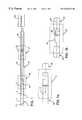
- FIG. 3is a schematic illustration of a single layer coil with passive tuning and active transmit detuning of the present invention.
- FIG. 4is a fragmentary enlarged illustration of the right-hand portion of the coil of FIG. 3 .
- FIG. 5is a fragmentary enlarged illustration of the left-hand portion of the coil of FIG. 3 .
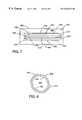
- FIG. 6is a schematic illustration of a single coil of the present invention with active transmit detuning.
- FIG. 7is a circuit diagram of a quadrature coil design employed on two sides of the printed circuit board substrate.
- FIG. 8is an illustration of the circuit board of FIG. 7 rolled so as to provide two loops which are perpendicular to each other.
- FIG. 9is a circuit diagram of an alternative single layer coil with passive tuning and active decoupling circuit.
- FIG. 10illustrates a transmit/receive coil having receive-only capabilities.
- FIG. 11is a circuit diagram of an embodiment having a built-in preamplifier.
- FIG. 12is a schematic cross-sectional illustration of a form of catheter coil of the present invention.
- the present inventionhas met the above described need.
- specimenshall refer to any object placed in the main magnetic field for imaging or spectroscopic analysis and shall expressly include, but not be limited to members of the animal kingdom, including humans, test specimens, such as biological tissue, for example, removed from such members of the animal kingdom and inanimate objects which may be imaged by magnetic resonance techniques or contain water or sources of other sensitive nuclei.
- patientshall mean human beings and other living members of the animal kingdom.
- body openingshall refer to preformed passageways of a patient within which a coil of the present invention is insertable with or without surgical intervention to effect access.
- body openingsshall expressly include blood vessels, the esophagus, bile ducts, rectal passageways, aortas, urethras, ears, nostrils, vaginas and bronchi.
- FIGS. 1, 1 a , and 1 billustrates a circuit diagram for a catheter coil which may function electrically in a manner identical to that disclosed in U.S. Pat. No. 5,699,801 in FIG. 5A thereof, but in the present invention would employ the new method of making a miniaturized coil and the resultant coil.
- the coil 2consists of two coil elements 4 , 6 having the ends electrically connected by an electrically conductive material 8 .
- the miniaturized coil 2is formed in accordance with the present invention employing printed circuit technology in a manner to be described hereinafter. For appropriate tuning and matching, at the time of manufacture, tuning/matching circuit 12 will be connected electrically to the ends of coil elements 4 and 6 .
- the tuning and matching circuit 12has a pair of capacitors 14 , 16 which are electrically connected to coil 2 .
- the other end of the tuning/matching circuit 12is connected to coaxial cable 20 which is adapted to transport the magnetic resonance signal received by the coil 2 to processor means (not shown).
- a catheter 17 and a pin diode device 22are placed in the coaxial cable 20 between segments 24 and 26 at box 27 in order to facilitate decoupling.
- the coil 2 , tuning/matching circuit 12 , coaxial cable 20 , and pin diode decoupling device 22will be referred to collectively herein as the “coil assembly.”
- the coil assemblyWhen the coil assembly is embedded within a catheter, it will be referred to as a “catheter coil.”
- the pin diode device 22turns on during RF transmission using DC current applied by the scanner hardware.
- the coaxial cable 20is provided for connection with the MR systems preamplifier 25 with a predetermined length 24 between the tuning/matching circuit 12 and the pin diode device 22 such that the diode device 22 is on the coaxial cable 20 and acts like an inductor and resonates with capacitor 16 to disable a current through the receiver coil 2 .
- the magnetic resonance scannermay provide a positive DC pulse to coil 2 for this purpose. This would normally turn on pin diode device 22 . When the pin diode device 22 is on, negligible current from the coil 2 is allowed to pass.
- the coils so mademay be used to send, to receive, or to both send and receive.
- the coilsmay be manufactured employing general printed circuit technology wherein a flexible circuit board made of a suitable, flexible, electrically insulative material, such as a polyimide (such as that sold under the trade designation “Kapton” by DuPont or polytetrafluoroethylene sold under the trade designation “Teflon” by DuPont) is used.
- a suitable, flexible, electrically insulative materialsuch as a polyimide (such as that sold under the trade designation “Kapton” by DuPont or polytetrafluoroethylene sold under the trade designation “Teflon” by DuPont) is used.
- the desired electrically conductive circuitis established by any of several means which may include etching techniques, electroplating, the use of electrically conductive inks or other suitable means.
- the electrically conductive portionmay consist of copper or copper with silver coating or other electrically conductive materials. This technique may permit production of very small coils which may have a width or maximum dimension on the order of about 1 mm.
- the coil assemblymay be inserted into a suitable sheath, such as a probe or catheter, in accordance with the teaching of U.S. Pat. No. 5,699,801 or in another desired surrounding housing for introduction into a patient or a patient's body opening.
- the catheterwhich may be made of a resinous plastic receiving the coil assembly, is identified generally by the reference number 11 in FIG. 1 .
- the miniaturized coils produced by the method of this inventionmay be employed with conventional magnetic resonance imaging equipment, computerized processing equipment, conventional probes and catheters suitably dimensioned for use in the particular body opening, and employing conventional techniques. They provide the added advantage of being mass-producible on an economic basis and being insertable into small body openings.
- the appropriate tuning and matching circuit 12 elementscan be calculated readily. If very low tolerance capacitors are employed, the values of the components and the tuning/matching circuit 12 need adjustment only during the initial design process. Once the design has been created, the coil assembly can be mass-produced with no tuning being required after manufacture.
- capacitors 14 , 16 in FIG. 1each be comprised of multiple capacitive elements in order to achieve optimum coil performance. For example, the use of 5 parallel capacitive elements for each capacitor 14 and capacitor 16 produced increases in the quality factor of the coil 2 from about 7.5 to about 20.
- the capacitor selectedwill preferably have fixed values selected to tune the coil at the desired NMR frequency.
- the capacitor valuesmay be selected initially and then the coil dimensions adjusted to achieve the desired NMR tuning frequency. This is accomplished by adjusting the inductance of the coil which depends on coil width, length, and number of turns. This can readily be accomplished by employing the circuit board method of manufacturing of the present invention. Once the proper size capacitors 14 , 16 has been selected, this becomes the specification for use in the photolithographic technique employed in fabricating the inductor and capacitors. As a result, rapid, economical mass-production of the coils is permitted.
- Capacitors 14 , 16may be employed to match the printed coil to the coaxial cable 20 , 26 (FIGS. 1, 1 a , 1 b ) and produce a desired resistive load to the preamplifier 25 .
- This loadmay be on the order of 50 ohms.
- the coil assemblymay be tuned to the desired MR frequency during manufacture by, prior to introducing the substrate into the catheter to create a catheter coil, adjusting at least one of the following: (a) the capacitive tuning means; and (b) the length of the conductive coil elements; and (c) the separation between adjacent coil elements.
- the coil 30basically consists of a first coil portion 32 having a generally uniform width through at least a major portion of its extent, a second coil portion 34 oriented generally parallel to the first coil portion 32 and having a generally uniform width throughout at least a major portion of its extent, and an integrally formed electrically conductive connecting end portion 36 .
- the overall coil length Lmay be about 1 to 30 cm.
- the average width of each coil portion 32 , 34may be about 0.05 to 5 cm.
- the average coil width Wmay be about 0.2 to 10 mm.
- the average thickness of the coilwill be about 0.1 to 5 mm.
- FIG. 2 ais an enlarged version of the portion of the coil of FIG. 2 contained within dashed circle A.
- the circuit board 42has a width W′ substantially greater than width W of the coil, which width W′ embraces both the width of the coil segments 32 , 34 , plus an additional increment of width due to portions 46 , 48 of the underlying flexible circuit board substrate portion.
- the coil 30will be severed from the circuit board 42 along generally parallel lines 50 , 52 which leaves substrate borders 47 , 49 .
- FIGS. 2 b and 2 care enlarged views of the portions of coil 30 of FIG. 2 contained within dashed circles B, C.
- FIG. 2 ashows the end of the coil. Electrically conductive portions 32 , 34 , 36 of the coil 30 are printed on substrate 42 .
- FIG. 2 bshows a section of the printed coil with pads 41 , 43 for placement of capacitive element 14 (FIG. 1 ).
- FIG. 2 cshows a portion of the printed coil with space 45 provided for capacitive element 16 (FIG. 1 ).
- the inner conductor of the coaxial cable 55may be connected to coil 30 at 49 and the shield of the coaxial cable 47 may be connected to coil 30 at 51 .
- FIG. 2 dshows the two parallel coil elements 32 , 34 secured in overlying relationship to the flexible electrically insulative circuit board base 42 having lateral sides 50 , 52 .
- the assemblyis conveniently provided in a suitable shroud 33 which may be in the form of a probe or catheter which is employed to introduce the coil assembly into a body opening.
- the probe or cathetermay be provided with one or more lumens or longitudinal passageways, such as 604 of FIG. 12, for example, for guidewires insertion, contrast material injection, or other purposes.
- the catheter coilmay have a generally circular cross-sectional configuration with a biocompatible resinous plastic covering the coil assembly and, if desired, one or more lumens or passageways formed within the resinous plastic and preferably being coextensive with the catheter.
- FIGS. 3 through 6show a single layer coil made on a flexible printed circuit board by conventional printed circuit means with copper being employed as the electrically conductive material.
- This coilhas passive pickup tuning and active transmit detuning.
- the board designmay be essentially the same as the design shown in FIGS. 1, 1 a , and 1 b except that a MOSFET is employed to provide a reliable and reproducible decoupling circuit.
- the MOSFETfunctions as an electronic switch to prevent the current from flowing on the coil during transmission of an RF pulse using an external coil. This design is easy to manufacture and does not require any adjustment during or after manufacture.
- the coil 120has a first electrically conductive portion 122 of generally uniform width oriented generally parallel to a second electrically conductive portion 124 of generally uniform width with a connecting electrically conductive portion 126 .
- FIG. 4shows an enlarged detail of the right-hand end of coil 120 shown in FIG. 3 .
- FIG. 5shows an enlarged view of end portion 130 shown in the left-hand portion on FIG. 3 .
- FIG. 6shows an embodiment with a circuit diagram which has a single coil with active transmit detuning.
- This circuitis employable with the printed circuit board shown in FIGS. 3 through 5.
- preamplifier 150amplifies the received signal.
- the circuitcontains capacitors 162 and 164 , inductive coil 170 and a MOSFET 174 .
- the MOSFET 174which preferably is an N-channel enhancement mode MOSFET, may be used to short the pickup inductor coil 170 .
- miniaturized coilsmay be provided employing two pairs of coils.
- the use of two pairs of coilswas disclosed in U.S. Pat. No. 5,699,801, the disclosure of which is expressly incorporated herein with reference, for example, to FIGS. 7 and 8 thereof.
- the quadrature structureis so provided that each of the two pairs of coils will be so oriented with respect to each other that their mutual inductance will be zero. This arrangement eliminates the need to align the pickup coil along the main magnetic field of the magnetic resonance scanner.
- the flexible circuit boardhas a first pair of electrically connected coils established on one side of the flexible circuit board and an offset second pair of electrically connected coils established on the other side of the circuit board.
- an electrically insulative generally rectangular flexible circuit board 200has a first surface 202 on which an electrically conductive path containing a first coil 204 consisting of a first coil segment 210 , a generally parallel second coil segment 212 , and an end electrically connecting portion 214 are provided.
- a first capacitor 220 and a second capacitor 222are provided in the circuit.
- a second coillaterally offset from the first coil by dotted line capacitors 244 , 246 are provided.
- FIG. 8By effecting relative closing movement of the edges 260 , 262 of electrically insulative board 202 in a direction downwardly into the page, the structure of FIG. 8 may be created.
- the boardmay be embedded into a resinous plastic material or introduced into a catheter to create a catheter coil or may be secured in the position of FIG. 8 by other suitable means, such as glue, for example.
- the capacitors 220 , 222 , 244 , 246may be separate electrical components secured to the board in electrical continuity with the coils.
- the outer conductors 210 , 212are generally diametrically opposed from each other and the inner conductors 230 , 232 are generally diametrically opposed to each other with a line diametrically connecting conductors 210 , 212 being generally perpendicular to a line diametrically connecting conductors 230 , 232 .
- FIG. 1shows a PIN diode device 22 for decoupling when the coil is employed in a receive-only mode.
- the catheter coilwill tend to distort the RF magnetic field during the transmit pulse by the external coil. It is, therefore, appropriate to provide a means for decoupling the external coil from the catheter coil during RF transmission in the receive-only mode. In this mode, an external coil is employed to transmit. If the coil is to function in the transmit/receive mode, the decoupling circuit is not needed.
- Coil 370has electrically connected portions 372 , 374 , 376 .
- the coaxial cable 381is operatively associated with circuit has a first capacitor 390 , a second capacitor 392 , an N-channel enhancement mode, and MOSFET 394 positioned to short circuit the tuning capacitor 392 thereby reducing the Q of the coil substantially. This occurs when a positive DC bias is supplied by the scanner hardware. This will serve to decrease the induced current on the coil to a desired very low level. When the DC bias is negative or zero, the MOSFET 394 behaves like an open circuit and, therefore, does not affect the tuning and matching. This properly may be employed to decouple the coil from the external coil during RF transmission.
- FIG. 10Another embodiment of the invention, shown in FIG. 10, involves the application of an RF current to the catheter coil with the opposing phase to the transmit coil during RF transmission to cancel any induced current in the catheter coil.
- a transmit/receive coil 402(which has no decoupling circuit) is employed in a receive-only mode.
- the circuitis shown in FIG. 10 wherein a preamplifier 400 emits an amplified signal through coaxial cable 404 to coil 402 which has capacitors 408 , 410 . No additional circuit for the catheter coil is required.
- Tuning of the pulse sequence before imagingwould be involved. The procedure for such tuning would involve applying a very weak RF power to the body coil (not shown) while the catheter coil is used for receiving the signal.
- the ratio of the signal received by the catheter coil to the applied RF signalis calculated.
- the phase difference between the applied RF pulse and the catheter coil received RF signalis calculated.
- the RF signalis applied to the catheter coil with the opposing phase and the same amplitude ratio with the RF pulses applied to the transmit coil during the MR imaging sequence. This serves to cancel the induced currents on the catheter coil.
- the advantage of this methodis that it does not require any decoupling circuit and, therefore, no tuning is necessary during the manufacturing process.
- the catheter coilcan be transformed to a transmit coil by turning off the RF power applied to the external coil. This approach is particularly useful in the implementation of cylindrical encoding procedures such as disclosed in U.S.
- an embodiment of the present inventionwherein the catheter coil 500 has a built-in preamplifier, will be considered.
- An MR scanner 488is operatively associated with coaxial cable 503 .
- Coil 500 , a tuning element which is shown as capacitor 501 and preamplifier 502are all positioned within a catheter 510 .
- the supply voltage and Vcc to operate the preamplifier 502may be supplied by another cable from the MR scanner (not shown). If desired, a decoupling circuit can be incorporated into this embodiment to resist current induction in the coil during transmission with an external coil.
- FIG. 12shows a cross-sectional illustration of a catheter coil 600 of the present invention wherein the coil assembly 602 is embedded in a biocompatible resinous material 606 of generally cylindrical shape.
- a lumen 604which may be coextensive with the catheter coil 600 , has been provided for receipt of a guidewire (not shown).
- the catheter coilmay be created by inserting the coil assembly 602 into a preformed catheter or by providing molten resinous material around the coil assembly 602 as by extrusion, coating or molding, for example.
- the present inventionhas provided a means for creating miniaturized coil assemblies for use in magnetic resonance imaging and spectrographic analysis with the coils being created by the use of the printed circuit board which can be introduced into a technology.
- the coil assembliesare of sufficiently small size as to be readily received within a catheter to create a catheter coil which can be introduced into a patient including body openings, including small body openings, such as small blood vessels. All of this is accomplished in a manner which is compatible with existing magnetic resonance imaging and spectrographic systems, including the magnetic field generating means, the RF pulse generating means, the microprocessor means, and all of the related system component and procedures.
- the coilsmay be disposable.
- the printed circuit boardwill have a thickness including any projection of the electrically conductive portion of less than about 0.1 to 10 mm.
- a plurality of coils each having a pair of coil elements which are electrically connectedmay be created on a single substrate with individual coils comprising a pair of electrically connected coil elements and a supporting substrate may be severed from the remainder of the coils to create individual coils.
Landscapes
- Physics & Mathematics (AREA)
- Condensed Matter Physics & Semiconductors (AREA)
- General Physics & Mathematics (AREA)
- Magnetic Resonance Imaging Apparatus (AREA)
Abstract
Description
Claims (63)
Priority Applications (7)
| Application Number | Priority Date | Filing Date | Title |
|---|---|---|---|
| US09/191,563US6263229B1 (en) | 1998-11-13 | 1998-11-13 | Miniature magnetic resonance catheter coils and related methods |
| PCT/US1999/026890WO2000028895A1 (en) | 1998-11-13 | 1999-11-12 | Miniature magnetic resonance catheter coils and related methods |
| CA002348867ACA2348867A1 (en) | 1998-11-13 | 1999-11-12 | Miniature magnetic resonance catheter coils and related methods |
| EP99961661AEP1128765A4 (en) | 1998-11-13 | 1999-11-12 | MINIATURE COILS FOR MAGNETIC RESONANCE CATHETERS AND CORRESPONDING METHODS |
| AU18189/00AAU775342B2 (en) | 1998-11-13 | 1999-11-12 | Miniature magnetic resonance catheter coils and related methods |
| US09/824,536US6898454B2 (en) | 1996-04-25 | 2001-04-02 | Systems and methods for evaluating the urethra and the periurethral tissues |
| US11/136,329US7599729B2 (en) | 1996-04-25 | 2005-05-24 | Evaluating the urethra and the periurethral tissues |
Applications Claiming Priority (1)
| Application Number | Priority Date | Filing Date | Title |
|---|---|---|---|
| US09/191,563US6263229B1 (en) | 1998-11-13 | 1998-11-13 | Miniature magnetic resonance catheter coils and related methods |
Related Parent Applications (2)
| Application Number | Title | Priority Date | Filing Date |
|---|---|---|---|
| US08/638,934Continuation-In-PartUS5928145A (en) | 1996-04-25 | 1996-04-25 | Method of magnetic resonance imaging and spectroscopic analysis and associated apparatus employing a loopless antenna |
| US09/817,893Continuation-In-PartUS6628980B2 (en) | 1996-04-25 | 2001-03-26 | Apparatus, systems, and methods for in vivo magnetic resonance imaging |
Related Child Applications (2)
| Application Number | Title | Priority Date | Filing Date |
|---|---|---|---|
| US36014499AContinuation-In-Part | 1996-04-25 | 1999-07-26 | |
| US09/824,536Continuation-In-PartUS6898454B2 (en) | 1996-04-25 | 2001-04-02 | Systems and methods for evaluating the urethra and the periurethral tissues |
Publications (1)
| Publication Number | Publication Date |
|---|---|
| US6263229B1true US6263229B1 (en) | 2001-07-17 |
Family
ID=22705988
Family Applications (1)
| Application Number | Title | Priority Date | Filing Date |
|---|---|---|---|
| US09/191,563Expired - LifetimeUS6263229B1 (en) | 1996-04-25 | 1998-11-13 | Miniature magnetic resonance catheter coils and related methods |
Country Status (5)
| Country | Link |
|---|---|
| US (1) | US6263229B1 (en) |
| EP (1) | EP1128765A4 (en) |
| AU (1) | AU775342B2 (en) |
| CA (1) | CA2348867A1 (en) |
| WO (1) | WO2000028895A1 (en) |
Cited By (155)
| Publication number | Priority date | Publication date | Assignee | Title |
|---|---|---|---|---|
| US6512941B1 (en)* | 1999-11-25 | 2003-01-28 | Koninklijke Philips Electronics N.V. | MR method for exciting the nuclear magnetization in a limited volume |
| US20030028094A1 (en)* | 1996-04-25 | 2003-02-06 | Ananda Kumar | Biopsy and sampling needle antennas for magnetic resonance imaging-guided biopsies |
| US20030050557A1 (en)* | 1998-11-04 | 2003-03-13 | Susil Robert C. | Systems and methods for magnetic-resonance-guided interventional procedures |
| US6549800B1 (en)* | 1996-04-25 | 2003-04-15 | Johns Hopkins Unversity School Of Medicine | Methods for in vivo magnetic resonance imaging |
| US20030097064A1 (en)* | 2001-11-13 | 2003-05-22 | Dnyanesh Talpade | Impedance-matching apparatus and construction for intravascular device |
| US20030187347A1 (en)* | 2001-02-15 | 2003-10-02 | Robin Medical Inc. | Endoscopic examining apparatus particularly useful in MRI, a probe useful in such apparatus, and a method of making such probe |
| US20030199755A1 (en)* | 1998-11-04 | 2003-10-23 | Johns Hopkins University School Of Medicine | System and method for magnetic-resonance-guided electrophysiologic and ablation procedures |
| US6675033B1 (en) | 1999-04-15 | 2004-01-06 | Johns Hopkins University School Of Medicine | Magnetic resonance imaging guidewire probe |
| US20040024301A1 (en)* | 2002-08-02 | 2004-02-05 | Frank Hockett | Method and apparatus for intracorporeal medical imaging using a self-tuned coil |
| US20040024308A1 (en)* | 2002-08-02 | 2004-02-05 | Wickline Samuel A. | Method and apparatus for intracorporeal medical imaging using self-tuned coils |
| US20040030242A1 (en)* | 2002-08-12 | 2004-02-12 | Jan Weber | Tunable MRI enhancing device |
| US20040045131A1 (en)* | 2002-09-10 | 2004-03-11 | Barnett Ricky William | Hinge assembly, and associated method, providing multiple axes of rotation |
| US6711440B2 (en) | 2002-04-11 | 2004-03-23 | Biophan Technologies, Inc. | MRI-compatible medical device with passive generation of optical sensing signals |
| US6714809B2 (en) | 2000-11-20 | 2004-03-30 | Surgi-Vision, Inc. | Connector and guidewire connectable thereto |
| US6718207B2 (en) | 2001-02-20 | 2004-04-06 | Biophan Technologies, Inc. | Electromagnetic interference immune tissue invasive system |
| US6725092B2 (en) | 2002-04-25 | 2004-04-20 | Biophan Technologies, Inc. | Electromagnetic radiation immune medical assist device adapter |
| US6731979B2 (en) | 2001-08-30 | 2004-05-04 | Biophan Technologies Inc. | Pulse width cardiac pacing apparatus |
| US20040116807A1 (en)* | 2002-10-17 | 2004-06-17 | Roni Amrami | Blood vessels wall imaging catheter |
| US6766185B2 (en)* | 2000-05-22 | 2004-07-20 | The Board Of Trustees Of The Leland Stanford Junior University | Transmission line techniques for MRI catheter coil miniaturization and tuning |
| US20040158144A1 (en)* | 2003-02-03 | 2004-08-12 | Topshooter Medical Imri Inc. | NMR probe particularly useful for intra-luminal imaging |
| US20040169514A1 (en)* | 2002-12-11 | 2004-09-02 | Friedrich Fuchs | Local coil for magnetic resonance applications |
| US6798204B2 (en)* | 2002-10-09 | 2004-09-28 | Igc - Medical Advances, Inc. | Local RF MRI coil using metal foil construction on a double-sided substrate with holes that directly pass DC conductors |
| US20040225213A1 (en)* | 2002-01-22 | 2004-11-11 | Xingwu Wang | Magnetic resonance imaging coated assembly |
| US20040236209A1 (en)* | 2002-05-16 | 2004-11-25 | Misic George J. | System and method of obtaining images and spectra of intracavity structures using 3.0 tesla magnetic resonance systems |
| US6829509B1 (en) | 2001-02-20 | 2004-12-07 | Biophan Technologies, Inc. | Electromagnetic interference immune tissue invasive system |
| US20050065437A1 (en)* | 2003-09-24 | 2005-03-24 | Scimed Life Systems, Inc. | Medical device with markers for magnetic resonance visibility |
| US6898454B2 (en) | 1996-04-25 | 2005-05-24 | The Johns Hopkins University | Systems and methods for evaluating the urethra and the periurethral tissues |
| US6925328B2 (en) | 2000-04-20 | 2005-08-02 | Biophan Technologies, Inc. | MRI-compatible implantable device |
| US20050205792A1 (en)* | 2004-01-13 | 2005-09-22 | Benny Rousso | Multi-dimensional image reconstruction |
| US20050251031A1 (en)* | 2004-05-06 | 2005-11-10 | Scimed Life Systems, Inc. | Apparatus and construction for intravascular device |
| US20050251032A1 (en)* | 2004-05-06 | 2005-11-10 | Scimed Life Systems, Inc. | Intravascular antenna |
| US6968236B2 (en) | 2002-01-28 | 2005-11-22 | Biophan Technologies, Inc. | Ceramic cardiac electrodes |
| US6980848B2 (en) | 2002-07-25 | 2005-12-27 | Biopham Technologies Inc. | Optical MRI catheter system |
| US6988001B2 (en) | 2001-10-31 | 2006-01-17 | Biophan Technologies, Inc. | Hermetic component housing for photonic catheter |
| US7054686B2 (en) | 2001-08-30 | 2006-05-30 | Biophan Technologies, Inc. | Pulsewidth electrical stimulation |
| US20060119361A1 (en)* | 2002-05-29 | 2006-06-08 | Surgi-Vision, Inc. | Magnetic resonance imaging probes |
| US20060129061A1 (en)* | 2004-12-15 | 2006-06-15 | Masayuki Kaneto | Catheter and production method thereof |
| US20060164089A1 (en)* | 2002-04-29 | 2006-07-27 | Patrick Gross | Magnetic resonance imaging receive circuit |
| WO2006103635A1 (en)* | 2005-04-01 | 2006-10-05 | Koninklijke Philips Electronics N.V. | Interventional device for use in a magntic resonance system |
| US20060237652A1 (en)* | 2000-08-21 | 2006-10-26 | Yoav Kimchy | Apparatus and methods for imaging and attenuation correction |
| US7162302B2 (en) | 2002-03-04 | 2007-01-09 | Nanoset Llc | Magnetically shielded assembly |
| US7172624B2 (en) | 2003-02-06 | 2007-02-06 | Boston Scientific Scimed, Inc. | Medical device with magnetic resonance visibility enhancing structure |
| US20070167725A1 (en)* | 2005-12-27 | 2007-07-19 | General Electric Company | Systems, methods and apparatus for an endo-rectal receive-only probe |
| US20070222433A1 (en)* | 2006-03-21 | 2007-09-27 | Radiation Monitoring Devices, Inc. | Sensor array for nuclear magnetic resonance imaging systems and method |
| US20080058913A1 (en)* | 2003-06-24 | 2008-03-06 | Biophan Technologies, Inc. | Magnetic resonance imaging interference immune device |
| US20080129435A1 (en)* | 2003-06-24 | 2008-06-05 | Medtronic, Inc. | Magnetic resonance imaging interference immune device |
| US20080183070A1 (en)* | 2007-01-29 | 2008-07-31 | Wisconsin Alumni Research Foundation | Multi-mode medical device system with thermal ablation capability and methods of using same |
| US20080306375A1 (en)* | 2007-06-07 | 2008-12-11 | Surgi-Vision, Inc. | Mri-guided medical interventional systems and methods |
| US20090076378A1 (en)* | 2004-11-15 | 2009-03-19 | Medrad, Inc. | Intracavity probes and interfaces therefor for use in obtaining images and spectra of intracavity structures using high field magnetic resonance systems |
| US20090112084A1 (en)* | 2007-06-07 | 2009-04-30 | Surgi-Vision, Inc. | Mri-guided medical interventional systems and methods |
| US20090118610A1 (en)* | 2005-11-29 | 2009-05-07 | Karmarkar Parag V | Mri-guided localization and/or lead placement systems, related methods, devices and computer program products |
| US20090131783A1 (en)* | 2007-11-21 | 2009-05-21 | Surgi-Vision, Inc. | Methods, systems and computer program products for positioning a guidance apparatus relative to a patient |
| US20090152471A1 (en)* | 2005-11-09 | 2009-06-18 | Spectrum Dynamics Llc | Dynamic Spect Camera |
| US20090177077A1 (en)* | 2007-09-24 | 2009-07-09 | Surgi-Vision, Inc. | Mri-compatible patches and methods for using the same |
| US20090216109A1 (en)* | 2005-10-06 | 2009-08-27 | Karmarkar Parag V | MRI Compatible Vascular Occlusive Devices and Related Methods of Treatment and Methods of Monitoring Implanted Devices |
| US20090273909A1 (en)* | 2004-09-10 | 2009-11-05 | Samsung Electronics Co., Ltd. | Flexible device, flexible pressure sensor, and fabrication method thereof |
| US20100063383A1 (en)* | 2008-09-11 | 2010-03-11 | Sunnybrook Health Sciences Centre | Catheter for magnetic resonance guided procedures |
| CN1802123B (en)* | 2002-05-16 | 2010-04-28 | 梅德拉股份有限公司 | System for acquiring intracavity structure image and spectrogram by using 3.0 Tesla magnetic resonance system |
| US7761138B2 (en) | 2004-03-12 | 2010-07-20 | Boston Scientific Scimed, Inc. | MRI and X-ray visualization |
| US20100185198A1 (en)* | 2007-09-24 | 2010-07-22 | Peter Piferi | Head Fixation Assemblies for Medical Procedures |
| US20100244835A1 (en)* | 2009-03-31 | 2010-09-30 | General Electric Company | Thin extended-cavity rf coil for mri |
| US7848788B2 (en) | 1999-04-15 | 2010-12-07 | The Johns Hopkins University | Magnetic resonance imaging probe |
| US20100317961A1 (en)* | 2009-06-16 | 2010-12-16 | Jenkins Kimble L | MRI-Guided Devices and MRI-Guided Interventional Systems that can Track and Generate Dynamic Visualizations of the Devices in near Real Time |
| US7872235B2 (en) | 2005-01-13 | 2011-01-18 | Spectrum Dynamics Llc | Multi-dimensional image reconstruction and analysis for expert-system diagnosis |
| US7968851B2 (en) | 2004-01-13 | 2011-06-28 | Spectrum Dynamics Llc | Dynamic spect camera |
| US8000773B2 (en) | 2004-11-09 | 2011-08-16 | Spectrum Dynamics Llc | Radioimaging |
| US8036731B2 (en) | 2001-01-22 | 2011-10-11 | Spectrum Dynamics Llc | Ingestible pill for diagnosing a gastrointestinal tract |
| US8055329B2 (en)* | 2001-01-22 | 2011-11-08 | Spectrum Dynamics Llc | Ingestible device for radioimaging of the gastrointestinal tract |
| US8095224B2 (en) | 2009-03-19 | 2012-01-10 | Greatbatch Ltd. | EMI shielded conduit assembly for an active implantable medical device |
| US8094894B2 (en) | 2000-08-21 | 2012-01-10 | Spectrum Dynamics Llc | Radioactive-emission-measurement optimization to specific body structures |
| US8111886B2 (en) | 2005-07-19 | 2012-02-07 | Spectrum Dynamics Llc | Reconstruction stabilizer and active vision |
| US8204500B2 (en) | 2005-12-28 | 2012-06-19 | Starhome Gmbh | Optimal voicemail deposit for roaming cellular telephony |
| US8219208B2 (en) | 2001-04-13 | 2012-07-10 | Greatbatch Ltd. | Frequency selective passive component networks for active implantable medical devices utilizing an energy dissipating surface |
| US8275466B2 (en) | 2006-06-08 | 2012-09-25 | Greatbatch Ltd. | Band stop filter employing a capacitor and an inductor tank circuit to enhance MRI compatibility of active medical devices |
| US20120242337A1 (en)* | 2010-11-25 | 2012-09-27 | Axel Krieger | MRI Imaging Probe |
| US8280124B2 (en) | 2004-06-01 | 2012-10-02 | Spectrum Dynamics Llc | Methods of view selection for radioactive emission measurements |
| US20120268116A1 (en)* | 2011-04-20 | 2012-10-25 | Haoqin Zhu | Magnetic Resonance Signal Detection Using Remotely Positioned Receive Coils |
| US8315689B2 (en) | 2007-09-24 | 2012-11-20 | MRI Interventions, Inc. | MRI surgical systems for real-time visualizations using MRI image data and predefined data of surgical tools |
| WO2012160518A1 (en)* | 2011-05-23 | 2012-11-29 | Koninklijke Philips Electronics N.V. | Fet switch as detune circuit for mri rf coils |
| US8338788B2 (en) | 2009-07-29 | 2012-12-25 | Spectrum Dynamics Llc | Method and system of optimized volumetric imaging |
| EP2549284A1 (en)* | 2011-07-21 | 2013-01-23 | Koninklijke Philips Electronics N.V. | Position marker for use in an MRI apparatus |
| US8364279B2 (en) | 2008-09-25 | 2013-01-29 | Boston Scientific Neuromodulation Corporation | Electrical stimulation leads having RF compatibility and methods of use and manufacture |
| US8445851B2 (en) | 2004-11-09 | 2013-05-21 | Spectrum Dynamics Llc | Radioimaging |
| US8447414B2 (en) | 2008-12-17 | 2013-05-21 | Greatbatch Ltd. | Switched safety protection circuit for an AIMD system during exposure to high power electromagnetic fields |
| US8457760B2 (en) | 2001-04-13 | 2013-06-04 | Greatbatch Ltd. | Switched diverter circuits for minimizing heating of an implanted lead and/or providing EMI protection in a high power electromagnetic field environment |
| US8489176B1 (en) | 2000-08-21 | 2013-07-16 | Spectrum Dynamics Llc | Radioactive emission detector equipped with a position tracking system and utilization thereof with medical systems and in medical procedures |
| US8509913B2 (en) | 2001-04-13 | 2013-08-13 | Greatbatch Ltd. | Switched diverter circuits for minimizing heating of an implanted lead and/or providing EMI protection in a high power electromagnetic field environment |
| US8521253B2 (en) | 2007-10-29 | 2013-08-27 | Spectrum Dynamics Llc | Prostate imaging |
| US8527046B2 (en) | 2000-04-20 | 2013-09-03 | Medtronic, Inc. | MRI-compatible implantable device |
| US8565860B2 (en) | 2000-08-21 | 2013-10-22 | Biosensors International Group, Ltd. | Radioactive emission detector equipped with a position tracking system |
| US8571881B2 (en) | 2004-11-09 | 2013-10-29 | Spectrum Dynamics, Llc | Radiopharmaceutical dispensing, administration, and imaging |
| US8600519B2 (en) | 2001-04-13 | 2013-12-03 | Greatbatch Ltd. | Transient voltage/current protection system for electronic circuits associated with implanted leads |
| US8606349B2 (en) | 2004-11-09 | 2013-12-10 | Biosensors International Group, Ltd. | Radioimaging using low dose isotope |
| US8610075B2 (en) | 2006-11-13 | 2013-12-17 | Biosensors International Group Ltd. | Radioimaging applications of and novel formulations of teboroxime |
| US8615405B2 (en) | 2004-11-09 | 2013-12-24 | Biosensors International Group, Ltd. | Imaging system customization using data from radiopharmaceutical-associated data carrier |
| CN103513200A (en)* | 2012-06-28 | 2014-01-15 | 西门子公司 | Automatic detuning of non-connected transceiver coils for mri |
| US8644910B2 (en) | 2005-07-19 | 2014-02-04 | Biosensors International Group, Ltd. | Imaging protocols |
| US8837793B2 (en) | 2005-07-19 | 2014-09-16 | Biosensors International Group, Ltd. | Reconstruction stabilizer and active vision |
| US8874228B2 (en) | 2004-07-27 | 2014-10-28 | The Cleveland Clinic Foundation | Integrated system and method for MRI-safe implantable devices |
| US8882763B2 (en) | 2010-01-12 | 2014-11-11 | Greatbatch Ltd. | Patient attached bonding strap for energy dissipation from a probe or a catheter during magnetic resonance imaging |
| US8894974B2 (en) | 2006-05-11 | 2014-11-25 | Spectrum Dynamics Llc | Radiopharmaceuticals for diagnosis and therapy |
| US8903505B2 (en) | 2006-06-08 | 2014-12-02 | Greatbatch Ltd. | Implantable lead bandstop filter employing an inductive coil with parasitic capacitance to enhance MRI compatibility of active medical devices |
| US8909325B2 (en) | 2000-08-21 | 2014-12-09 | Biosensors International Group, Ltd. | Radioactive emission detector equipped with a position tracking system and utilization thereof with medical systems and in medical procedures |
| US8977355B2 (en) | 2001-04-13 | 2015-03-10 | Greatbatch Ltd. | EMI filter employing a capacitor and an inductor tank circuit having optimum component values |
| US8979871B2 (en) | 2009-08-13 | 2015-03-17 | Monteris Medical Corporation | Image-guided therapy of a tissue |
| US8983574B2 (en) | 2009-11-17 | 2015-03-17 | The Brigham And Women's Hospital | Catheter device with local magnetic resonance imaging coil and methods for use thereof |
| US8989870B2 (en) | 2001-04-13 | 2015-03-24 | Greatbatch Ltd. | Tuned energy balanced system for minimizing heating and/or to provide EMI protection of implanted leads in a high power electromagnetic field environment |
| US9040016B2 (en) | 2004-01-13 | 2015-05-26 | Biosensors International Group, Ltd. | Diagnostic kit and methods for radioimaging myocardial perfusion |
| US9108066B2 (en) | 2008-03-20 | 2015-08-18 | Greatbatch Ltd. | Low impedance oxide resistant grounded capacitor for an AIMD |
| US20150323621A1 (en)* | 2013-09-04 | 2015-11-12 | Hubert Noras | Rectal coil for magnetic-resonance tomography |
| US9186052B1 (en)* | 1997-10-06 | 2015-11-17 | Micro-Imagaing Solutions | Reduced area imaging device incorporated within endoscopic devices |
| US9192446B2 (en) | 2012-09-05 | 2015-11-24 | MRI Interventions, Inc. | Trajectory guide frame for MRI-guided surgeries |
| US9242090B2 (en) | 2001-04-13 | 2016-01-26 | MRI Interventions Inc. | MRI compatible medical leads |
| US9248283B2 (en) | 2001-04-13 | 2016-02-02 | Greatbatch Ltd. | Band stop filter comprising an inductive component disposed in a lead wire in series with an electrode |
| US9259290B2 (en) | 2009-06-08 | 2016-02-16 | MRI Interventions, Inc. | MRI-guided surgical systems with proximity alerts |
| US9275451B2 (en) | 2006-12-20 | 2016-03-01 | Biosensors International Group, Ltd. | Method, a system, and an apparatus for using and processing multidimensional data |
| US9295828B2 (en) | 2001-04-13 | 2016-03-29 | Greatbatch Ltd. | Self-resonant inductor wound portion of an implantable lead for enhanced MRI compatibility of active implantable medical devices |
| US9316743B2 (en) | 2004-11-09 | 2016-04-19 | Biosensors International Group, Ltd. | System and method for radioactive emission measurement |
| US9333038B2 (en) | 2000-06-15 | 2016-05-10 | Monteris Medical Corporation | Hyperthermia treatment and probe therefore |
| US20160158509A1 (en)* | 2013-07-29 | 2016-06-09 | Imricor Medical Systems, Inc. | Actively tracked medical devices |
| US9417299B2 (en) | 2009-06-19 | 2016-08-16 | Koninklijke Philips N.V. | Using memristor devices as switches for MRI RF coils |
| US9427596B2 (en) | 2013-01-16 | 2016-08-30 | Greatbatch Ltd. | Low impedance oxide resistant grounded capacitor for an AIMD |
| US9433383B2 (en) | 2014-03-18 | 2016-09-06 | Monteris Medical Corporation | Image-guided therapy of a tissue |
| US9470801B2 (en) | 2004-01-13 | 2016-10-18 | Spectrum Dynamics Llc | Gating with anatomically varying durations |
| US9504484B2 (en) | 2014-03-18 | 2016-11-29 | Monteris Medical Corporation | Image-guided therapy of a tissue |
| WO2017083498A1 (en)* | 2015-11-11 | 2017-05-18 | University Of Utah Research Foundation | Endoenteric balloon coil |
| WO2017142698A1 (en) | 2016-02-17 | 2017-08-24 | MRI Interventions, Inc. | Intrabody surgical fluid transfer assemblies with adjustable exposed cannula to needle tip length, related systems and methods |
| US9782581B2 (en) | 2014-06-27 | 2017-10-10 | Boston Scientific Neuromodulation Corporation | Methods and systems for electrical stimulation including a shielded sheath |
| US9782582B2 (en) | 2015-03-27 | 2017-10-10 | Boston Scientific Neuromodulation Corporation | Systems and methods for making and using electrical stimulation systems to reduce RF-induced tissue heating |
| USRE46699E1 (en) | 2013-01-16 | 2018-02-06 | Greatbatch Ltd. | Low impedance oxide resistant grounded capacitor for an AIMD |
| US9891296B2 (en) | 2013-09-13 | 2018-02-13 | MRI Interventions, Inc. | Intrabody fluid transfer devices, systems and methods |
| US9927504B2 (en) | 2012-09-12 | 2018-03-27 | Toshiba Medical Systems Corporation | Magnetic resonance imaging apparatus |
| US9931514B2 (en) | 2013-06-30 | 2018-04-03 | Greatbatch Ltd. | Low impedance oxide resistant grounded capacitor for an AIMD |
| US10080889B2 (en) | 2009-03-19 | 2018-09-25 | Greatbatch Ltd. | Low inductance and low resistance hermetically sealed filtered feedthrough for an AIMD |
| US10105485B2 (en) | 2010-04-16 | 2018-10-23 | MRI Interventions, Inc. | MRI surgical systems including MRI-compatible surgical cannulae for transferring a substance to and/or from a patient |
| US10136865B2 (en) | 2004-11-09 | 2018-11-27 | Spectrum Dynamics Medical Limited | Radioimaging using low dose isotope |
| US10173055B2 (en) | 2015-04-30 | 2019-01-08 | Boston Scientific Neuromodulation Corporaation | Electrical stimulation leads and systems having a RF shield along at least the lead and methods of making and using |
| US10327830B2 (en) | 2015-04-01 | 2019-06-25 | Monteris Medical Corporation | Cryotherapy, thermal therapy, temperature modulation therapy, and probe apparatus therefor |
| US10350421B2 (en) | 2013-06-30 | 2019-07-16 | Greatbatch Ltd. | Metallurgically bonded gold pocket pad for grounding an EMI filter to a hermetic terminal for an active implantable medical device |
| US10398505B2 (en) | 2011-04-21 | 2019-09-03 | Koninklijke Philips N.V. | MR imaging guided therapy system |
| EP3586781A1 (en) | 2018-06-26 | 2020-01-01 | Biosense Webster (Israel) Ltd. | Magnetic pickup cancellation by compensation leads |
| US10559409B2 (en) | 2017-01-06 | 2020-02-11 | Greatbatch Ltd. | Process for manufacturing a leadless feedthrough for an active implantable medical device |
| US10561837B2 (en) | 2011-03-01 | 2020-02-18 | Greatbatch Ltd. | Low equivalent series resistance RF filter for an active implantable medical device utilizing a ceramic reinforced metal composite filled via |
| US10589107B2 (en) | 2016-11-08 | 2020-03-17 | Greatbatch Ltd. | Circuit board mounted filtered feedthrough assembly having a composite conductive lead for an AIMD |
| US10675113B2 (en) | 2014-03-18 | 2020-06-09 | Monteris Medical Corporation | Automated therapy of a three-dimensional tissue region |
| US10905497B2 (en) | 2017-04-21 | 2021-02-02 | Clearpoint Neuro, Inc. | Surgical navigation systems |
| US10905888B2 (en) | 2018-03-22 | 2021-02-02 | Greatbatch Ltd. | Electrical connection for an AIMD EMI filter utilizing an anisotropic conductive layer |
| US10912945B2 (en) | 2018-03-22 | 2021-02-09 | Greatbatch Ltd. | Hermetic terminal for an active implantable medical device having a feedthrough capacitor partially overhanging a ferrule for high effective capacitance area |
| WO2021071561A1 (en) | 2019-10-08 | 2021-04-15 | Clearpoint Neuro, Inc. | Extension tube assembly and related medical fluid transfer systems and methods |
| US11022664B2 (en) | 2018-05-09 | 2021-06-01 | Clearpoint Neuro, Inc. | MRI compatible intrabody fluid transfer systems and related devices and methods |
| WO2021126336A1 (en) | 2019-12-19 | 2021-06-24 | Clearpoint Neuro, Inc. | Front-loadable fluid transfer assemblies and related medical fluid transfer systems |
| EP3892214A1 (en) | 2020-04-08 | 2021-10-13 | ClearPoint Neuro, Inc. | Mri surgical systems including mri-compatible surgical cannulas for transferring a substance to and/or from a patient |
| US11198014B2 (en) | 2011-03-01 | 2021-12-14 | Greatbatch Ltd. | Hermetically sealed filtered feedthrough assembly having a capacitor with an oxide resistant electrical connection to an active implantable medical device housing |
| US11253237B2 (en) | 2018-05-09 | 2022-02-22 | Clearpoint Neuro, Inc. | MRI compatible intrabody fluid transfer systems and related devices and methods |
| US20250076426A1 (en)* | 2022-01-06 | 2025-03-06 | The Regents Of The University Of California | Flexible Radiofrequency (RF) Coil for Small Field-of-View Magnetic Resonance Imaging (MRI) |
Families Citing this family (6)
| Publication number | Priority date | Publication date | Assignee | Title |
|---|---|---|---|---|
| WO2010142998A2 (en)* | 2009-06-11 | 2010-12-16 | Imperial Innovations Limited | Radio frequency detector coils |
| US9864026B2 (en)* | 2011-03-29 | 2018-01-09 | The Government Of The United States Of America, As Represented By The Secretary, Department Of Health And Human Services | Wirelessly powered magnetic resonance imaging signal amplification system |
| US10874456B2 (en) | 2017-10-25 | 2020-12-29 | Biosense Webster (Israel) Ltd. | Integrated LC filters in catheter distal end |
| US10893902B2 (en) | 2017-10-25 | 2021-01-19 | Biosense Webster (Israel) Ltd. | Integrated resistive filters in catheter distal end |
| FR3077392A1 (en)* | 2018-01-26 | 2019-08-02 | Universite De Montpellier (Um) | COIL SYSTEM FOR USE IN NUCLEAR MAGNETIC RESONANCE AND NUCLEAR MAGNETIC RESONANCE IMAGING |
| EP4253980A1 (en) | 2022-03-29 | 2023-10-04 | Koninklijke Philips N.V. | Tunable radio frequency coil assembly and magnetic resonance system comprising the rf coil assembly |
Citations (68)
| Publication number | Priority date | Publication date | Assignee | Title |
|---|---|---|---|---|
| US4431005A (en) | 1981-05-07 | 1984-02-14 | Mccormick Laboratories, Inc. | Method of and apparatus for determining very accurately the position of a device inside biological tissue |
| US4445501A (en) | 1981-05-07 | 1984-05-01 | Mccormick Laboratories, Inc. | Circuits for determining very accurately the position of a device inside biological tissue |
| US4572198A (en) | 1984-06-18 | 1986-02-25 | Varian Associates, Inc. | Catheter for use with NMR imaging systems |
| US4672972A (en) | 1984-08-13 | 1987-06-16 | Berke Howard R | Solid state NMR probe |
| US4766381A (en) | 1987-08-12 | 1988-08-23 | Vanderbilt University | Driven inversion spin echo magnetic resonance imaging |
| US4791372A (en) | 1987-08-17 | 1988-12-13 | Resonex, Inc. | Conformable head or body coil assembly for magnetic imaging apparatus |
| US4793356A (en) | 1985-08-14 | 1988-12-27 | Picker International, Inc. | Surface coil system for magnetic resonance imaging |
| US4823812A (en) | 1986-05-12 | 1989-04-25 | Biodan Medical Systems Ltd. | Applicator for insertion into a body opening for medical purposes |
| US4897604A (en)* | 1989-02-21 | 1990-01-30 | The Regents Of The University Of California | Method and apparatus for selective adjustment of RF coil size for magnetic resonance imaging |
| US4922204A (en) | 1988-04-11 | 1990-05-01 | Siemens Aktiengesellschaft | Arrangement for operating a symmetrical radio-frequency antenna in a nuclear magnetic resonance tomography apparatus |
| US4932411A (en) | 1984-08-09 | 1990-06-12 | Siemens Aktiengesellschaft | Intervivo coil for a nuclear magnetic resonance tomographic apparatus |
| US4960106A (en) | 1987-04-28 | 1990-10-02 | Olympus Optical Co., Ltd. | Endoscope apparatus |
| US5050607A (en) | 1987-03-04 | 1991-09-24 | Huntington Medical Research Institutes | High resolution magnetic resonance imaging of body cavities |
| US5099208A (en) | 1989-10-05 | 1992-03-24 | Vanderbilt University | Method for magnetic resonance imaging and related apparatus |
| US5167233A (en) | 1991-01-07 | 1992-12-01 | Endosonics Corporation | Dilating and imaging apparatus |
| US5170789A (en) | 1987-06-17 | 1992-12-15 | Perinchery Narayan | Insertable NMR coil probe |
| US5211165A (en) | 1991-09-03 | 1993-05-18 | General Electric Company | Tracking system to follow the position and orientation of a device with radiofrequency field gradients |
| US5217010A (en) | 1991-05-28 | 1993-06-08 | The Johns Hopkins University | Ecg amplifier and cardiac pacemaker for use during magnetic resonance imaging |
| US5260658A (en) | 1990-12-10 | 1993-11-09 | Siemens Aktiengesellschaft | Detuning circuit for resonators in a nuclear magnetic resonance imaging apparatus |
| US5270485A (en) | 1991-01-28 | 1993-12-14 | Sarcos Group | High density, three-dimensional, intercoupled circuit structure |
| US5271400A (en) | 1992-04-01 | 1993-12-21 | General Electric Company | Tracking system to monitor the position and orientation of a device using magnetic resonance detection of a sample contained within the device |
| JPH0670902A (en) | 1992-08-28 | 1994-03-15 | Hitachi Ltd | MRI device and endoscope probe for MRI |
| US5294886A (en) | 1991-04-22 | 1994-03-15 | Siemens Aktiengesellschaft | Antenna system for a magnetic resonance imaging tomography apparatus |
| US5307808A (en) | 1992-04-01 | 1994-05-03 | General Electric Company | Tracking system and pulse sequences to monitor the position of a device using magnetic resonance |
| US5307814A (en) | 1991-09-17 | 1994-05-03 | Medrad, Inc. | Externally moveable intracavity probe for MRI imaging and spectroscopy |
| US5318025A (en) | 1992-04-01 | 1994-06-07 | General Electric Company | Tracking system to monitor the position and orientation of a device using multiplexed magnetic resonance detection |
| US5323778A (en) | 1991-11-05 | 1994-06-28 | Brigham & Women's Hospital | Method and apparatus for magnetic resonance imaging and heating tissues |
| US5348010A (en) | 1989-02-24 | 1994-09-20 | Medrea, Inc., Pennsylvania Corp., Pa. | Intracavity probe and interface device for MRI imaging and spectroscopy |
| US5355087A (en) | 1989-02-27 | 1994-10-11 | Medrad, Inc. | Intracavity probe and interface device for MRI imaging and spectroscopy |
| US5358515A (en) | 1989-08-16 | 1994-10-25 | Deutsches Krebsforschungzentrum Stiftung Des Offentlichen Rechts | Microwave hyperthermia applicator |
| US5365928A (en) | 1992-11-25 | 1994-11-22 | Medrad, Inc. | Endorectal probe with planar moveable MRI coil |
| US5370644A (en) | 1988-11-25 | 1994-12-06 | Sensor Electronics, Inc. | Radiofrequency ablation catheter |
| US5375596A (en) | 1992-09-29 | 1994-12-27 | Hdc Corporation | Method and apparatus for determining the position of catheters, tubes, placement guidewires and implantable ports within biological tissue |
| US5400787A (en) | 1993-11-24 | 1995-03-28 | Magna-Lab, Inc. | Inflatable magnetic resonance imaging sensing coil assembly positioning and retaining device and method for using the same |
| US5413104A (en) | 1992-11-10 | 1995-05-09 | Drager Medical Electronics B.V. | Invasive MRI transducers |
| US5419325A (en) | 1994-06-23 | 1995-05-30 | General Electric Company | Magnetic resonance (MR) angiography using a faraday catheter |
| US5429132A (en) | 1990-08-24 | 1995-07-04 | Imperial College Of Science Technology And Medicine | Probe system |
| US5435302A (en)* | 1988-09-09 | 1995-07-25 | Medrad, Inc. | Flexible surface coils for use in nuclear magnetic resonance imaging |
| US5437277A (en) | 1991-11-18 | 1995-08-01 | General Electric Company | Inductively coupled RF tracking system for use in invasive imaging of a living body |
| US5443066A (en) | 1991-11-18 | 1995-08-22 | General Electric Company | Invasive system employing a radiofrequency tracking system |
| US5443489A (en) | 1993-07-20 | 1995-08-22 | Biosense, Inc. | Apparatus and method for ablation |
| US5447156A (en) | 1994-04-04 | 1995-09-05 | General Electric Company | Magnetic resonance (MR) active invasive devices for the generation of selective MR angiograms |
| US5451774A (en) | 1991-12-31 | 1995-09-19 | Sarcos Group | High density, three-dimensional, intercoupled optical sensor circuit |
| US5451232A (en) | 1991-10-07 | 1995-09-19 | Medrad, Inc. | Probe for MRI imaging and spectroscopy particularly in the cervical region |
| US5462055A (en) | 1994-08-23 | 1995-10-31 | Northrop Grumman Corporation | MRI/hyperthermia dual function antenna system |
| US5498261A (en) | 1991-12-20 | 1996-03-12 | Advanced Cardiovascular Systems, Inc. | Thermal angioplasty system |
| US5507743A (en) | 1993-11-08 | 1996-04-16 | Zomed International | Coiled RF electrode treatment apparatus |
| US5512825A (en) | 1994-11-25 | 1996-04-30 | The Johns Hopkins University | Method of minimizing dead-periods in magnetic resonance imaging pulse sequences and associated apparatus |
| US5520644A (en) | 1991-11-18 | 1996-05-28 | Intelliwire, Inc. | Flexible elongate device having steerable distal extremity and apparatus for use therewith and method |
| US5524630A (en) | 1988-03-21 | 1996-06-11 | Crowley; Robert J. | Acoustic imaging catheter and the like |
| US5558093A (en) | 1990-05-18 | 1996-09-24 | Cardiovascular Imaging Systems, Inc. | Guidewire with imaging capability |
| US5588432A (en) | 1988-03-21 | 1996-12-31 | Boston Scientific Corporation | Catheters for imaging, sensing electrical potentials, and ablating tissue |
| US5623241A (en) | 1992-09-11 | 1997-04-22 | Magna-Lab, Inc. | Permanent magnetic structure |
| US5699801A (en) | 1995-06-01 | 1997-12-23 | The Johns Hopkins University | Method of internal magnetic resonance imaging and spectroscopic analysis and associated apparatus |
| US5728079A (en) | 1994-09-19 | 1998-03-17 | Cordis Corporation | Catheter which is visible under MRI |
| US5775338A (en) | 1997-01-10 | 1998-07-07 | Scimed Life Systems, Inc. | Heated perfusion balloon for reduction of restenosis |
| US5792055A (en) | 1994-03-18 | 1998-08-11 | Schneider (Usa) Inc. | Guidewire antenna |
| US5840031A (en) | 1993-07-01 | 1998-11-24 | Boston Scientific Corporation | Catheters for imaging, sensing electrical potentials and ablating tissue |
| WO1998052461A1 (en) | 1997-05-21 | 1998-11-26 | Cardiac M.R.I., Inc. | Cardiac mri with an internal receiving coil and an external receiving coil |
| US5868674A (en) | 1995-11-24 | 1999-02-09 | U.S. Philips Corporation | MRI-system and catheter for interventional procedures |
| US5928145A (en) | 1996-04-25 | 1999-07-27 | The Johns Hopkins University | Method of magnetic resonance imaging and spectroscopic analysis and associated apparatus employing a loopless antenna |
| US5938692A (en) | 1996-03-26 | 1999-08-17 | Urologix, Inc. | Voltage controlled variable tuning antenna |
| US5964705A (en) | 1997-08-22 | 1999-10-12 | Image-Guided Drug Delivery System, Inc. | MR-compatible medical devices |
| US6004269A (en) | 1993-07-01 | 1999-12-21 | Boston Scientific Corporation | Catheters for imaging, sensing electrical potentials, and ablating tissue |
| US6026316A (en) | 1997-05-15 | 2000-02-15 | Regents Of The University Of Minnesota | Method and apparatus for use with MR imaging |
| US6031375A (en) | 1997-11-26 | 2000-02-29 | The Johns Hopkins University | Method of magnetic resonance analysis employing cylindrical coordinates and an associated apparatus |
| US6051974A (en) | 1997-11-26 | 2000-04-18 | Picker International, Inc. | MRI endocavitary coils and decontamination |
| US6104943A (en)* | 1997-11-14 | 2000-08-15 | The Mclean Hospital Corporation | Phased array echoplanar imaging system for fMRI |
Family Cites Families (4)
| Publication number | Priority date | Publication date | Assignee | Title |
|---|---|---|---|---|
| US5035231A (en)* | 1987-04-27 | 1991-07-30 | Olympus Optical Co., Ltd. | Endoscope apparatus |
| US5427103A (en)* | 1992-06-29 | 1995-06-27 | Olympus Optical Co., Ltd. | MRI apparatus for receiving nuclear-magnetic resonance signals of a living body |
| NL1004381C2 (en)* | 1996-10-30 | 1998-05-08 | Cordis Europ | Balloon-type catheter |
| JPH10262944A (en)* | 1997-03-24 | 1998-10-06 | Olympus Optical Co Ltd | Antenna system for nmr measurement |
- 1998
- 1998-11-13USUS09/191,563patent/US6263229B1/ennot_activeExpired - Lifetime
- 1999
- 1999-11-12AUAU18189/00Apatent/AU775342B2/ennot_activeExpired
- 1999-11-12CACA002348867Apatent/CA2348867A1/ennot_activeAbandoned
- 1999-11-12EPEP99961661Apatent/EP1128765A4/ennot_activeWithdrawn
- 1999-11-12WOPCT/US1999/026890patent/WO2000028895A1/enactiveIP Right Grant
Patent Citations (73)
| Publication number | Priority date | Publication date | Assignee | Title |
|---|---|---|---|---|
| US4445501A (en) | 1981-05-07 | 1984-05-01 | Mccormick Laboratories, Inc. | Circuits for determining very accurately the position of a device inside biological tissue |
| US4431005A (en) | 1981-05-07 | 1984-02-14 | Mccormick Laboratories, Inc. | Method of and apparatus for determining very accurately the position of a device inside biological tissue |
| US4572198A (en) | 1984-06-18 | 1986-02-25 | Varian Associates, Inc. | Catheter for use with NMR imaging systems |
| US4932411A (en) | 1984-08-09 | 1990-06-12 | Siemens Aktiengesellschaft | Intervivo coil for a nuclear magnetic resonance tomographic apparatus |
| US4672972A (en) | 1984-08-13 | 1987-06-16 | Berke Howard R | Solid state NMR probe |
| US4793356A (en) | 1985-08-14 | 1988-12-27 | Picker International, Inc. | Surface coil system for magnetic resonance imaging |
| US4823812A (en) | 1986-05-12 | 1989-04-25 | Biodan Medical Systems Ltd. | Applicator for insertion into a body opening for medical purposes |
| US5050607A (en) | 1987-03-04 | 1991-09-24 | Huntington Medical Research Institutes | High resolution magnetic resonance imaging of body cavities |
| US4960106A (en) | 1987-04-28 | 1990-10-02 | Olympus Optical Co., Ltd. | Endoscope apparatus |
| US5170789A (en) | 1987-06-17 | 1992-12-15 | Perinchery Narayan | Insertable NMR coil probe |
| US4766381A (en) | 1987-08-12 | 1988-08-23 | Vanderbilt University | Driven inversion spin echo magnetic resonance imaging |
| US4791372A (en) | 1987-08-17 | 1988-12-13 | Resonex, Inc. | Conformable head or body coil assembly for magnetic imaging apparatus |
| US5588432A (en) | 1988-03-21 | 1996-12-31 | Boston Scientific Corporation | Catheters for imaging, sensing electrical potentials, and ablating tissue |
| US5715825A (en) | 1988-03-21 | 1998-02-10 | Boston Scientific Corporation | Acoustic imaging catheter and the like |
| US5524630A (en) | 1988-03-21 | 1996-06-11 | Crowley; Robert J. | Acoustic imaging catheter and the like |
| US4922204A (en) | 1988-04-11 | 1990-05-01 | Siemens Aktiengesellschaft | Arrangement for operating a symmetrical radio-frequency antenna in a nuclear magnetic resonance tomography apparatus |
| US5435302A (en)* | 1988-09-09 | 1995-07-25 | Medrad, Inc. | Flexible surface coils for use in nuclear magnetic resonance imaging |
| US5370644A (en) | 1988-11-25 | 1994-12-06 | Sensor Electronics, Inc. | Radiofrequency ablation catheter |
| US4897604A (en)* | 1989-02-21 | 1990-01-30 | The Regents Of The University Of California | Method and apparatus for selective adjustment of RF coil size for magnetic resonance imaging |
| US5348010A (en) | 1989-02-24 | 1994-09-20 | Medrea, Inc., Pennsylvania Corp., Pa. | Intracavity probe and interface device for MRI imaging and spectroscopy |
| US5476095A (en) | 1989-02-24 | 1995-12-19 | Medrad, Inc. | Intracavity probe and interface device for MRI imaging and spectroscopy |
| US5355087A (en) | 1989-02-27 | 1994-10-11 | Medrad, Inc. | Intracavity probe and interface device for MRI imaging and spectroscopy |
| US5358515A (en) | 1989-08-16 | 1994-10-25 | Deutsches Krebsforschungzentrum Stiftung Des Offentlichen Rechts | Microwave hyperthermia applicator |
| US5099208A (en) | 1989-10-05 | 1992-03-24 | Vanderbilt University | Method for magnetic resonance imaging and related apparatus |
| US5682897A (en) | 1990-05-18 | 1997-11-04 | Cardiovascular Imaging Systems, Inc. | Guidewire with imaging capability |
| US5558093A (en) | 1990-05-18 | 1996-09-24 | Cardiovascular Imaging Systems, Inc. | Guidewire with imaging capability |
| US5938609A (en) | 1990-05-18 | 1999-08-17 | Cardiovascular Imaging Systems, Inc. | Guidewire with imaging capability |
| US5429132A (en) | 1990-08-24 | 1995-07-04 | Imperial College Of Science Technology And Medicine | Probe system |
| US5260658A (en) | 1990-12-10 | 1993-11-09 | Siemens Aktiengesellschaft | Detuning circuit for resonators in a nuclear magnetic resonance imaging apparatus |
| US5167233A (en) | 1991-01-07 | 1992-12-01 | Endosonics Corporation | Dilating and imaging apparatus |
| US5270485A (en) | 1991-01-28 | 1993-12-14 | Sarcos Group | High density, three-dimensional, intercoupled circuit structure |
| US5294886A (en) | 1991-04-22 | 1994-03-15 | Siemens Aktiengesellschaft | Antenna system for a magnetic resonance imaging tomography apparatus |
| US5217010A (en) | 1991-05-28 | 1993-06-08 | The Johns Hopkins University | Ecg amplifier and cardiac pacemaker for use during magnetic resonance imaging |
| US5211165A (en) | 1991-09-03 | 1993-05-18 | General Electric Company | Tracking system to follow the position and orientation of a device with radiofrequency field gradients |
| US5307814A (en) | 1991-09-17 | 1994-05-03 | Medrad, Inc. | Externally moveable intracavity probe for MRI imaging and spectroscopy |
| US5451232A (en) | 1991-10-07 | 1995-09-19 | Medrad, Inc. | Probe for MRI imaging and spectroscopy particularly in the cervical region |
| US5323778A (en) | 1991-11-05 | 1994-06-28 | Brigham & Women's Hospital | Method and apparatus for magnetic resonance imaging and heating tissues |
| US5520644A (en) | 1991-11-18 | 1996-05-28 | Intelliwire, Inc. | Flexible elongate device having steerable distal extremity and apparatus for use therewith and method |
| US5437277A (en) | 1991-11-18 | 1995-08-01 | General Electric Company | Inductively coupled RF tracking system for use in invasive imaging of a living body |
| US5443066A (en) | 1991-11-18 | 1995-08-22 | General Electric Company | Invasive system employing a radiofrequency tracking system |
| US5498261A (en) | 1991-12-20 | 1996-03-12 | Advanced Cardiovascular Systems, Inc. | Thermal angioplasty system |
| US5451774A (en) | 1991-12-31 | 1995-09-19 | Sarcos Group | High density, three-dimensional, intercoupled optical sensor circuit |
| US5307808A (en) | 1992-04-01 | 1994-05-03 | General Electric Company | Tracking system and pulse sequences to monitor the position of a device using magnetic resonance |
| US5318025A (en) | 1992-04-01 | 1994-06-07 | General Electric Company | Tracking system to monitor the position and orientation of a device using multiplexed magnetic resonance detection |
| US5271400A (en) | 1992-04-01 | 1993-12-21 | General Electric Company | Tracking system to monitor the position and orientation of a device using magnetic resonance detection of a sample contained within the device |
| JPH0670902A (en) | 1992-08-28 | 1994-03-15 | Hitachi Ltd | MRI device and endoscope probe for MRI |
| US5623241A (en) | 1992-09-11 | 1997-04-22 | Magna-Lab, Inc. | Permanent magnetic structure |
| US5375596A (en) | 1992-09-29 | 1994-12-27 | Hdc Corporation | Method and apparatus for determining the position of catheters, tubes, placement guidewires and implantable ports within biological tissue |
| US5413104A (en) | 1992-11-10 | 1995-05-09 | Drager Medical Electronics B.V. | Invasive MRI transducers |
| US5365928A (en) | 1992-11-25 | 1994-11-22 | Medrad, Inc. | Endorectal probe with planar moveable MRI coil |
| US5840031A (en) | 1993-07-01 | 1998-11-24 | Boston Scientific Corporation | Catheters for imaging, sensing electrical potentials and ablating tissue |
| US6004269A (en) | 1993-07-01 | 1999-12-21 | Boston Scientific Corporation | Catheters for imaging, sensing electrical potentials, and ablating tissue |
| US5443489A (en) | 1993-07-20 | 1995-08-22 | Biosense, Inc. | Apparatus and method for ablation |
| US5507743A (en) | 1993-11-08 | 1996-04-16 | Zomed International | Coiled RF electrode treatment apparatus |
| US5400787A (en) | 1993-11-24 | 1995-03-28 | Magna-Lab, Inc. | Inflatable magnetic resonance imaging sensing coil assembly positioning and retaining device and method for using the same |
| US5792055A (en) | 1994-03-18 | 1998-08-11 | Schneider (Usa) Inc. | Guidewire antenna |
| US5447156A (en) | 1994-04-04 | 1995-09-05 | General Electric Company | Magnetic resonance (MR) active invasive devices for the generation of selective MR angiograms |
| US5419325A (en) | 1994-06-23 | 1995-05-30 | General Electric Company | Magnetic resonance (MR) angiography using a faraday catheter |
| US5462055A (en) | 1994-08-23 | 1995-10-31 | Northrop Grumman Corporation | MRI/hyperthermia dual function antenna system |
| US5728079A (en) | 1994-09-19 | 1998-03-17 | Cordis Corporation | Catheter which is visible under MRI |
| US5512825A (en) | 1994-11-25 | 1996-04-30 | The Johns Hopkins University | Method of minimizing dead-periods in magnetic resonance imaging pulse sequences and associated apparatus |
| US5699801A (en) | 1995-06-01 | 1997-12-23 | The Johns Hopkins University | Method of internal magnetic resonance imaging and spectroscopic analysis and associated apparatus |
| US5868674A (en) | 1995-11-24 | 1999-02-09 | U.S. Philips Corporation | MRI-system and catheter for interventional procedures |
| US5938692A (en) | 1996-03-26 | 1999-08-17 | Urologix, Inc. | Voltage controlled variable tuning antenna |
| US6032078A (en) | 1996-03-26 | 2000-02-29 | Urologix, Inc. | Voltage controlled variable tuning antenna |
| US5928145A (en) | 1996-04-25 | 1999-07-27 | The Johns Hopkins University | Method of magnetic resonance imaging and spectroscopic analysis and associated apparatus employing a loopless antenna |
| US5775338A (en) | 1997-01-10 | 1998-07-07 | Scimed Life Systems, Inc. | Heated perfusion balloon for reduction of restenosis |
| US6026316A (en) | 1997-05-15 | 2000-02-15 | Regents Of The University Of Minnesota | Method and apparatus for use with MR imaging |
| WO1998052461A1 (en) | 1997-05-21 | 1998-11-26 | Cardiac M.R.I., Inc. | Cardiac mri with an internal receiving coil and an external receiving coil |
| US5964705A (en) | 1997-08-22 | 1999-10-12 | Image-Guided Drug Delivery System, Inc. | MR-compatible medical devices |
| US6104943A (en)* | 1997-11-14 | 2000-08-15 | The Mclean Hospital Corporation | Phased array echoplanar imaging system for fMRI |
| US6031375A (en) | 1997-11-26 | 2000-02-29 | The Johns Hopkins University | Method of magnetic resonance analysis employing cylindrical coordinates and an associated apparatus |
| US6051974A (en) | 1997-11-26 | 2000-04-18 | Picker International, Inc. | MRI endocavitary coils and decontamination |
Non-Patent Citations (25)
| Title |
|---|
| Asdente et al., Evaluation of Atherosclerotic Lesions Using NMR Microimaging, Atherosclerosis, 1990, pp. 243-253 vol. 80 (Italy). |
| Atalar et al.; "High Resolution Intravascular MRI and MRS using a Catheter Receiver Coil,", Magnetic Resonance in Medicine, 63:596-605 (1996). |
| Dumoulin et al., Real-Time Position Monitoring of Invasive Devices Using Magnetic Resonance, Magnetic Resonance in Medicine, Mar. 1993, pp. 411-415, vol. 29. |
| Edelman et al.; "Magnetic Resonance Imaging" NEJM. 328: 708-716 (1993). |
| Farmer et al., "Implanted Coil MR Microscopy of RenalPathology", Magn. Reson. Med., 10: 310-323 (1989). |
| Garwood et al.; "Magnetic Resonance Imaging with Adiabatic Using a Single Surface Coil for RF Transmission and Signal Detection", Magnetic Resonance in Medicine 9: 25-34 (1989). |
| Hoult et al.; "The Signal-to-Noise Ratio of the Nuclear Magnetic Resonance Experiment" J. Magn. Reson., 24: 71-85 (1976). |
| Hoult; "Rotating Frame Zeugmatography", Phil. Trans. R. Soc. Lond. B. 289: 543-547 (1980). |
| Hurst et al., Intravascular (Catheter) NMR Receiver Probe: Preliminary Design Analysis and Application to Canine Iliofemoral ImagingMagn. Resonance in Medicine, Apr. 1992, pp. 343-357, vol. 24. |
| Jolesz et al.; "Interventional Magnetic Resonance Therapy", Seminars in Interventional Radiology , 12: 20-27 (1995). |
| Kantor et al., In vivo 31P Nuclear Magnetic Resonance Measuremetns in Canine Heart Using a Catheter-Coil Circulation Research, Aug. 1984, pp. 261-266, vol. 55, No. 2 (USA). |
| Koechli et al., Catheters and Guide Wires for Use in an Echo-Planar MR Fluoroscopy System, R. 79th Scientific Meeting, editor, Radiology, Nov. 1993, p. 319, vol. 189(P). |
| Martin et al., Intravascular MR Imaging in a Porcine Animal Model, Magn. Resonance in Medicine, Aug. 1994, pp. 224-229, vol. 32. |
| Martin et al., MR Imaging of Blood Vessel with an Intravascular Coil, J. Magn. Reson. Imaging, 1992, pp. 421-429, vol. 2. |
| Maynor et al., Chemical Shift Imaging of Atherosclerosis at 7.0 Telsa, Investigative Radiology, Jan. 1989, pp. 52-60, vol. 24, No. 1. |
| McDonald et al., Performance Comparison of Several Coil Geometries for Use in Catheters (Abstract), R. 79th Scientific Meeting, editor, Radiology, Nov. 1993, p. 319, vol. 189(P). |
| Merickel et al., ndentification and 3-d Quantification of Atherosclerosis Using Magnetics Resonance Imaging, Comput. Biol. Med., 1988, pp. 89-102, vol. 18, (Great Britain). |
| Merickel et al., Noninvasive Quantative Evaluation of Ather.sclerosis Using MRI and Image Analysis, Arteriosclerosis and Thrombosis, 1993, pp. 1180-1186, vol. 13. |
| Mohiaddin et al., Chemical Shift Magnetic Resonance Imaging of Human Atheroma, Br. Heart J., 1989, pp. 81-89, vol. 62 (England). |
| Ocali et al.; "Intravascular Magnetic Resonance Imaging Using a Loopless Catheter Antenna", MRM, 37: 112-118 (1997). |
| Pearlman et al., Nuclear Magnetic Resonance Microscopy of Atheroma in Human Coronary Arteries, Angiology, Sep. 1991, pp. 726-733, vol. 42 (USA). |
| Spears et al.,In Vivo coronary Angioscopy, Journal of the American Colege of Cardiology, May 1993, pp. 1311-1314, vol. 1 (USA). |
| Vinitski et al., Magnetic Resonance Chemical Shift Imaging and Spectroscopy of Atherosclerotic Plaque, Investigative Radiology, Aug. 1991, pp. 703-747, vol. 26. |
| Waller et al., Intravascular Ultrasound: A hoistological Study of Vessel During Life, Circulation, Jun. 1992, pp. 2305-2310, vol. 85. |
| Yuan et al., Techniques for High-Resolution MR Imaging Of Atherosclerotic Plaque, J. Magnetic Resonance Imaging, 1994, pp. 43-49, vol. 4, No. 1. |
Cited By (311)
| Publication number | Priority date | Publication date | Assignee | Title |
|---|---|---|---|---|
| US7236816B2 (en) | 1996-04-25 | 2007-06-26 | Johns Hopkins University | Biopsy and sampling needle antennas for magnetic resonance imaging-guided biopsies |
| US6898454B2 (en) | 1996-04-25 | 2005-05-24 | The Johns Hopkins University | Systems and methods for evaluating the urethra and the periurethral tissues |
| US6549800B1 (en)* | 1996-04-25 | 2003-04-15 | Johns Hopkins Unversity School Of Medicine | Methods for in vivo magnetic resonance imaging |
| US7599729B2 (en) | 1996-04-25 | 2009-10-06 | The Johns Hopkins University | Evaluating the urethra and the periurethral tissues |
| US20070238978A1 (en)* | 1996-04-25 | 2007-10-11 | Johns Hopkins University | Biopsy and Sampling Needle Antennas for Magnetic Resonance Imaging-Guided Biopsies |
| US20060122493A1 (en)* | 1996-04-25 | 2006-06-08 | Surgi-Vision, Inc. | Evaluating the urethra and the periurethral Tissues |
| US7778682B2 (en) | 1996-04-25 | 2010-08-17 | Johns Hopkins University | Biopsy and sampling needle antennas for magnetic resonance imaging-guided biopsies |
| US20030028094A1 (en)* | 1996-04-25 | 2003-02-06 | Ananda Kumar | Biopsy and sampling needle antennas for magnetic resonance imaging-guided biopsies |
| US9186052B1 (en)* | 1997-10-06 | 2015-11-17 | Micro-Imagaing Solutions | Reduced area imaging device incorporated within endoscopic devices |
| US9198565B2 (en) | 1997-10-06 | 2015-12-01 | Micro-Imaging Solutions | Reduced area imaging device incorporated within endoscopic devices |
| US9667896B2 (en)* | 1997-10-06 | 2017-05-30 | Cellect Llc | Reduced area imaging device incorporated within endoscopic devices |
| US9301705B2 (en) | 1998-11-04 | 2016-04-05 | Johns Hopkins University School Of Medicine | System and method for magnetic-resonance-guided electrophysiologic and ablation procedures |
| US7155271B2 (en) | 1998-11-04 | 2006-12-26 | Johns Hopkins University School Of Medicine | System and method for magnetic-resonance-guided electrophysiologic and ablation procedures |
| US7412276B2 (en) | 1998-11-04 | 2008-08-12 | Johns Hopkins University School Of Medicine | Brain therapy |
| US7822460B2 (en) | 1998-11-04 | 2010-10-26 | Surgi-Vision, Inc. | MRI-guided therapy methods and related systems |
| US20030050557A1 (en)* | 1998-11-04 | 2003-03-13 | Susil Robert C. | Systems and methods for magnetic-resonance-guided interventional procedures |
| US8099151B2 (en) | 1998-11-04 | 2012-01-17 | Johns Hopkins University School Of Medicine | System and method for magnetic-resonance-guided electrophysiologic and ablation procedures |
| US7844319B2 (en) | 1998-11-04 | 2010-11-30 | Susil Robert C | Systems and methods for magnetic-resonance-guided interventional procedures |
| US20040167392A1 (en)* | 1998-11-04 | 2004-08-26 | Halperin Henry R. | Brain therapy |
| US20030199755A1 (en)* | 1998-11-04 | 2003-10-23 | Johns Hopkins University School Of Medicine | System and method for magnetic-resonance-guided electrophysiologic and ablation procedures |
| US6675033B1 (en) | 1999-04-15 | 2004-01-06 | Johns Hopkins University School Of Medicine | Magnetic resonance imaging guidewire probe |
| US7848788B2 (en) | 1999-04-15 | 2010-12-07 | The Johns Hopkins University | Magnetic resonance imaging probe |
| US6512941B1 (en)* | 1999-11-25 | 2003-01-28 | Koninklijke Philips Electronics N.V. | MR method for exciting the nuclear magnetization in a limited volume |
| US6925328B2 (en) | 2000-04-20 | 2005-08-02 | Biophan Technologies, Inc. | MRI-compatible implantable device |
| US8527046B2 (en) | 2000-04-20 | 2013-09-03 | Medtronic, Inc. | MRI-compatible implantable device |
| US6766185B2 (en)* | 2000-05-22 | 2004-07-20 | The Board Of Trustees Of The Leland Stanford Junior University | Transmission line techniques for MRI catheter coil miniaturization and tuning |
| US9387042B2 (en) | 2000-06-15 | 2016-07-12 | Monteris Medical Corporation | Hyperthermia treatment and probe therefor |
| US9333038B2 (en) | 2000-06-15 | 2016-05-10 | Monteris Medical Corporation | Hyperthermia treatment and probe therefore |
| US7652259B2 (en) | 2000-08-21 | 2010-01-26 | Spectrum Dynamics Llc | Apparatus and methods for imaging and attenuation correction |
| US8489176B1 (en) | 2000-08-21 | 2013-07-16 | Spectrum Dynamics Llc | Radioactive emission detector equipped with a position tracking system and utilization thereof with medical systems and in medical procedures |
| US9370333B2 (en) | 2000-08-21 | 2016-06-21 | Biosensors International Group, Ltd. | Radioactive-emission-measurement optimization to specific body structures |
| US8909325B2 (en) | 2000-08-21 | 2014-12-09 | Biosensors International Group, Ltd. | Radioactive emission detector equipped with a position tracking system and utilization thereof with medical systems and in medical procedures |
| US8620046B2 (en) | 2000-08-21 | 2013-12-31 | Biosensors International Group, Ltd. | Radioactive-emission-measurement optimization to specific body structures |
| US20060237652A1 (en)* | 2000-08-21 | 2006-10-26 | Yoav Kimchy | Apparatus and methods for imaging and attenuation correction |
| US8565860B2 (en) | 2000-08-21 | 2013-10-22 | Biosensors International Group, Ltd. | Radioactive emission detector equipped with a position tracking system |
| US8094894B2 (en) | 2000-08-21 | 2012-01-10 | Spectrum Dynamics Llc | Radioactive-emission-measurement optimization to specific body structures |
| US20040181177A1 (en)* | 2000-11-20 | 2004-09-16 | Chris Lee | Guidewire and connector therefor |
| US6714809B2 (en) | 2000-11-20 | 2004-03-30 | Surgi-Vision, Inc. | Connector and guidewire connectable thereto |
| US9179857B2 (en) | 2000-11-20 | 2015-11-10 | MRI Interventions, Inc. | Guidewire and connector therefor |
| US8055329B2 (en)* | 2001-01-22 | 2011-11-08 | Spectrum Dynamics Llc | Ingestible device for radioimaging of the gastrointestinal tract |
| US8036731B2 (en) | 2001-01-22 | 2011-10-11 | Spectrum Dynamics Llc | Ingestible pill for diagnosing a gastrointestinal tract |
| US6871086B2 (en) | 2001-02-15 | 2005-03-22 | Robin Medical Inc. | Endoscopic examining apparatus particularly useful in MRI, a probe useful in such apparatus, and a method of making such probe |
| US20050171427A1 (en)* | 2001-02-15 | 2005-08-04 | Robin Medical Inc. | Endoscopic examining apparatus particularly useful in MRI, a probe useful in such apparatus, and a method of making such probe |
| US20030187347A1 (en)* | 2001-02-15 | 2003-10-02 | Robin Medical Inc. | Endoscopic examining apparatus particularly useful in MRI, a probe useful in such apparatus, and a method of making such probe |
| US7047074B2 (en) | 2001-02-20 | 2006-05-16 | Biophan Technologies, Inc. | Electromagnetic interference immune tissue invasive system |
| US6819958B2 (en) | 2001-02-20 | 2004-11-16 | Biophan Technologies, Inc. | Electromagnetic interference immune tissue invasive system |
| US6954674B2 (en) | 2001-02-20 | 2005-10-11 | Biophan Technologies, Inc. | Electromagnetic interference immune tissue invasive system |
| US6850805B2 (en) | 2001-02-20 | 2005-02-01 | Biophan Technologies, Inc. | Electromagnetic interference immune tissue invasive system |
| US6845266B2 (en) | 2001-02-20 | 2005-01-18 | Biophan Technologies, Inc. | Electromagnetic interference immune tissue invasive system |
| US6763268B2 (en) | 2001-02-20 | 2004-07-13 | Biophan Technologies, Inc. | Electromagnetic interference immune tissue invasive system |
| US7450996B2 (en) | 2001-02-20 | 2008-11-11 | Medtronic, Inc. | Medical device with an electrically conductive anti-antenna geometrical shaped member |
| US6760628B2 (en) | 2001-02-20 | 2004-07-06 | Biophan Technologies, Inc. | Electromagnetic interference immune tissue invasive system |
| US6993387B2 (en) | 2001-02-20 | 2006-01-31 | Biophan Technologies, Inc. | Electromagnetic interference immune tissue invasive system |
| US7010357B2 (en) | 2001-02-20 | 2006-03-07 | Biophan Technologies, Inc. | Electromagnetic interference immune tissue invasive system |
| US7013174B2 (en) | 2001-02-20 | 2006-03-14 | Biophan Technologies, Inc. | Electromagnetic interference immune tissue invasive system |
| US6829509B1 (en) | 2001-02-20 | 2004-12-07 | Biophan Technologies, Inc. | Electromagnetic interference immune tissue invasive system |
| US6778856B2 (en) | 2001-02-20 | 2004-08-17 | Biophan Technologies, Inc. | Electromagnetic interference immune tissue invasive system |
| US6795736B2 (en) | 2001-02-20 | 2004-09-21 | Biophan Technologies, Inc. | Electromagnetic interference immune tissue invasive system |
| US6757566B2 (en) | 2001-02-20 | 2004-06-29 | Biophan Technologies, Inc. | Electromagnetic interference immune tissue invasive system |
| US6718207B2 (en) | 2001-02-20 | 2004-04-06 | Biophan Technologies, Inc. | Electromagnetic interference immune tissue invasive system |
| US6718203B2 (en) | 2001-02-20 | 2004-04-06 | Biophan Technologies, Inc. | Electromagnetic interference immune tissue invasive system |
| US6799069B2 (en) | 2001-02-20 | 2004-09-28 | Biophan Technologies, Inc. | Electromagnetic interference immune tissue invasive system |
| US6901290B2 (en) | 2001-02-20 | 2005-05-31 | Biophan Technologies, Inc. | Electromagnetic interference immune tissue invasive system |
| US6819954B2 (en) | 2001-02-20 | 2004-11-16 | Biophan Technologies, Inc. | Electromagnetic interference immune tissue invasive system |
| US9295828B2 (en) | 2001-04-13 | 2016-03-29 | Greatbatch Ltd. | Self-resonant inductor wound portion of an implantable lead for enhanced MRI compatibility of active implantable medical devices |
| US8977355B2 (en) | 2001-04-13 | 2015-03-10 | Greatbatch Ltd. | EMI filter employing a capacitor and an inductor tank circuit having optimum component values |
| US8219208B2 (en) | 2001-04-13 | 2012-07-10 | Greatbatch Ltd. | Frequency selective passive component networks for active implantable medical devices utilizing an energy dissipating surface |
| US8855785B1 (en) | 2001-04-13 | 2014-10-07 | Greatbatch Ltd. | Circuits for minimizing heating of an implanted lead and/or providing EMI protection in a high power electromagnetic field environment |
| US8989870B2 (en) | 2001-04-13 | 2015-03-24 | Greatbatch Ltd. | Tuned energy balanced system for minimizing heating and/or to provide EMI protection of implanted leads in a high power electromagnetic field environment |
| US8457760B2 (en) | 2001-04-13 | 2013-06-04 | Greatbatch Ltd. | Switched diverter circuits for minimizing heating of an implanted lead and/or providing EMI protection in a high power electromagnetic field environment |
| US9242090B2 (en) | 2001-04-13 | 2016-01-26 | MRI Interventions Inc. | MRI compatible medical leads |
| US8751013B2 (en) | 2001-04-13 | 2014-06-10 | Greatbatch Ltd. | Switched diverter circuits for minimizing heating of an implanted lead and/or providing EMI protection in a high power electromagnetic field environment |
| US9248283B2 (en) | 2001-04-13 | 2016-02-02 | Greatbatch Ltd. | Band stop filter comprising an inductive component disposed in a lead wire in series with an electrode |
| US8509913B2 (en) | 2001-04-13 | 2013-08-13 | Greatbatch Ltd. | Switched diverter circuits for minimizing heating of an implanted lead and/or providing EMI protection in a high power electromagnetic field environment |
| US8600519B2 (en) | 2001-04-13 | 2013-12-03 | Greatbatch Ltd. | Transient voltage/current protection system for electronic circuits associated with implanted leads |
| US7054686B2 (en) | 2001-08-30 | 2006-05-30 | Biophan Technologies, Inc. | Pulsewidth electrical stimulation |
| US6731979B2 (en) | 2001-08-30 | 2004-05-04 | Biophan Technologies Inc. | Pulse width cardiac pacing apparatus |
| US6988001B2 (en) | 2001-10-31 | 2006-01-17 | Biophan Technologies, Inc. | Hermetic component housing for photonic catheter |
| US7194297B2 (en)* | 2001-11-13 | 2007-03-20 | Boston Scientific Scimed, Inc. | Impedance-matching apparatus and construction for intravascular device |
| US20030097064A1 (en)* | 2001-11-13 | 2003-05-22 | Dnyanesh Talpade | Impedance-matching apparatus and construction for intravascular device |
| US20060118319A1 (en)* | 2002-01-22 | 2006-06-08 | Xingwu Wang | Magnetic resonance imaging coated assembly |
| US20040225213A1 (en)* | 2002-01-22 | 2004-11-11 | Xingwu Wang | Magnetic resonance imaging coated assembly |
| US7473843B2 (en) | 2002-01-22 | 2009-01-06 | Biophan Technologies, Inc. | Magnetic resonance imaging coated assembly |
| US6968236B2 (en) | 2002-01-28 | 2005-11-22 | Biophan Technologies, Inc. | Ceramic cardiac electrodes |
| US7162302B2 (en) | 2002-03-04 | 2007-01-09 | Nanoset Llc | Magnetically shielded assembly |
| US6711440B2 (en) | 2002-04-11 | 2004-03-23 | Biophan Technologies, Inc. | MRI-compatible medical device with passive generation of optical sensing signals |
| US6725092B2 (en) | 2002-04-25 | 2004-04-20 | Biophan Technologies, Inc. | Electromagnetic radiation immune medical assist device adapter |
| US20060164089A1 (en)* | 2002-04-29 | 2006-07-27 | Patrick Gross | Magnetic resonance imaging receive circuit |
| US7180296B2 (en) | 2002-04-29 | 2007-02-20 | Imperial College Innovations Limited | Magnetic resonance imaging receive circuit |
| US8989841B2 (en) | 2002-05-16 | 2015-03-24 | Bayer Medical Care Inc. | Interface devices for use with intracavity probes for high field strength magnetic resonance systems |
| US20040236209A1 (en)* | 2002-05-16 | 2004-11-25 | Misic George J. | System and method of obtaining images and spectra of intracavity structures using 3.0 tesla magnetic resonance systems |
| US7747310B2 (en) | 2002-05-16 | 2010-06-29 | Medrad, Inc. | System and method of obtaining images and spectra of intracavity structures using 3.0 Tesla magnetic resonance systems |
| CN1802123B (en)* | 2002-05-16 | 2010-04-28 | 梅德拉股份有限公司 | System for acquiring intracavity structure image and spectrogram by using 3.0 Tesla magnetic resonance system |
| WO2003098236A3 (en)* | 2002-05-16 | 2009-06-18 | Medrad Inc | System and method of obtaining images and spectra of intracavity structures using 3.0 tesla magnetic resonance systems |
| US7133714B2 (en)* | 2002-05-29 | 2006-11-07 | Surgi-Vision, Inc. | Magnetic resonance imaging probes |
| USRE44736E1 (en) | 2002-05-29 | 2014-01-28 | MRI Interventions, Inc. | Magnetic resonance probes |
| US20060119361A1 (en)* | 2002-05-29 | 2006-06-08 | Surgi-Vision, Inc. | Magnetic resonance imaging probes |
| USRE42856E1 (en) | 2002-05-29 | 2011-10-18 | MRI Interventions, Inc. | Magnetic resonance probes |
| US7389137B2 (en) | 2002-07-25 | 2008-06-17 | Biophan Technologies, Inc. | Optical MRI catheter system |
| US6980848B2 (en) | 2002-07-25 | 2005-12-27 | Biopham Technologies Inc. | Optical MRI catheter system |
| US20040024308A1 (en)* | 2002-08-02 | 2004-02-05 | Wickline Samuel A. | Method and apparatus for intracorporeal medical imaging using self-tuned coils |
| US7096057B2 (en) | 2002-08-02 | 2006-08-22 | Barnes Jewish Hospital | Method and apparatus for intracorporeal medical imaging using a self-tuned coil |
| US20040024301A1 (en)* | 2002-08-02 | 2004-02-05 | Frank Hockett | Method and apparatus for intracorporeal medical imaging using a self-tuned coil |
| US20040030242A1 (en)* | 2002-08-12 | 2004-02-12 | Jan Weber | Tunable MRI enhancing device |
| US7725160B2 (en) | 2002-08-12 | 2010-05-25 | Boston Scientific Scimed, Inc. | Tunable MRI enhancing device |
| US20040045131A1 (en)* | 2002-09-10 | 2004-03-11 | Barnett Ricky William | Hinge assembly, and associated method, providing multiple axes of rotation |
| US6798204B2 (en)* | 2002-10-09 | 2004-09-28 | Igc - Medical Advances, Inc. | Local RF MRI coil using metal foil construction on a double-sided substrate with holes that directly pass DC conductors |
| US20040116807A1 (en)* | 2002-10-17 | 2004-06-17 | Roni Amrami | Blood vessels wall imaging catheter |
| US6823206B2 (en)* | 2002-12-11 | 2004-11-23 | Siemens Aktiengesellschaft | Local coil for magnetic resonance applications |
| US20040169514A1 (en)* | 2002-12-11 | 2004-09-02 | Friedrich Fuchs | Local coil for magnetic resonance applications |
| US20040158144A1 (en)* | 2003-02-03 | 2004-08-12 | Topshooter Medical Imri Inc. | NMR probe particularly useful for intra-luminal imaging |
| US7172624B2 (en) | 2003-02-06 | 2007-02-06 | Boston Scientific Scimed, Inc. | Medical device with magnetic resonance visibility enhancing structure |
| US20070123975A1 (en)* | 2003-02-06 | 2007-05-31 | Jan Weber | Medical device with magnetic resonance visibility enhancing structure |
| US20080058913A1 (en)* | 2003-06-24 | 2008-03-06 | Biophan Technologies, Inc. | Magnetic resonance imaging interference immune device |
| US7742825B2 (en)* | 2003-06-24 | 2010-06-22 | Medtronic, Inc. | Magnetic resonance imaging interference immune device |
| US20080129435A1 (en)* | 2003-06-24 | 2008-06-05 | Medtronic, Inc. | Magnetic resonance imaging interference immune device |
| US7729777B2 (en) | 2003-06-24 | 2010-06-01 | Medtronic, Inc. | Magnetic resonance imaging interference immune device |
| US7839146B2 (en) | 2003-06-24 | 2010-11-23 | Medtronic, Inc. | Magnetic resonance imaging interference immune device |
| US20050065437A1 (en)* | 2003-09-24 | 2005-03-24 | Scimed Life Systems, Inc. | Medical device with markers for magnetic resonance visibility |
| US8676292B2 (en) | 2004-01-13 | 2014-03-18 | Biosensors International Group, Ltd. | Multi-dimensional image reconstruction |
| US7968851B2 (en) | 2004-01-13 | 2011-06-28 | Spectrum Dynamics Llc | Dynamic spect camera |
| US20050205792A1 (en)* | 2004-01-13 | 2005-09-22 | Benny Rousso | Multi-dimensional image reconstruction |
| US7176466B2 (en) | 2004-01-13 | 2007-02-13 | Spectrum Dynamics Llc | Multi-dimensional image reconstruction |
| US9470801B2 (en) | 2004-01-13 | 2016-10-18 | Spectrum Dynamics Llc | Gating with anatomically varying durations |
| US10964075B2 (en) | 2004-01-13 | 2021-03-30 | Spectrum Dynamics Llc | Gating with anatomically varying durations |
| US9040016B2 (en) | 2004-01-13 | 2015-05-26 | Biosensors International Group, Ltd. | Diagnostic kit and methods for radioimaging myocardial perfusion |
| US7761138B2 (en) | 2004-03-12 | 2010-07-20 | Boston Scientific Scimed, Inc. | MRI and X-ray visualization |
| US7496397B2 (en) | 2004-05-06 | 2009-02-24 | Boston Scientific Scimed, Inc. | Intravascular antenna |
| US20050251031A1 (en)* | 2004-05-06 | 2005-11-10 | Scimed Life Systems, Inc. | Apparatus and construction for intravascular device |
| US8116846B2 (en) | 2004-05-06 | 2012-02-14 | Boston Scientific Scimed, Inc. | Intravascular antenna |
| US20050251032A1 (en)* | 2004-05-06 | 2005-11-10 | Scimed Life Systems, Inc. | Intravascular antenna |
| US20080208043A1 (en)* | 2004-05-06 | 2008-08-28 | Smith Scott R | Apparatus and construction for intravascular device |
| US9943278B2 (en) | 2004-06-01 | 2018-04-17 | Spectrum Dynamics Medical Limited | Radioactive-emission-measurement optimization to specific body structures |
| US8280124B2 (en) | 2004-06-01 | 2012-10-02 | Spectrum Dynamics Llc | Methods of view selection for radioactive emission measurements |
| US8874228B2 (en) | 2004-07-27 | 2014-10-28 | The Cleveland Clinic Foundation | Integrated system and method for MRI-safe implantable devices |
| US8107248B2 (en)* | 2004-09-10 | 2012-01-31 | Samsung Electronics Co., Ltd. | Flexible device, flexible pressure sensor |
| US20090273909A1 (en)* | 2004-09-10 | 2009-11-05 | Samsung Electronics Co., Ltd. | Flexible device, flexible pressure sensor, and fabrication method thereof |
| US9316743B2 (en) | 2004-11-09 | 2016-04-19 | Biosensors International Group, Ltd. | System and method for radioactive emission measurement |
| US10136865B2 (en) | 2004-11-09 | 2018-11-27 | Spectrum Dynamics Medical Limited | Radioimaging using low dose isotope |
| US8423125B2 (en) | 2004-11-09 | 2013-04-16 | Spectrum Dynamics Llc | Radioimaging |
| US8445851B2 (en) | 2004-11-09 | 2013-05-21 | Spectrum Dynamics Llc | Radioimaging |
| US8000773B2 (en) | 2004-11-09 | 2011-08-16 | Spectrum Dynamics Llc | Radioimaging |
| US8571881B2 (en) | 2004-11-09 | 2013-10-29 | Spectrum Dynamics, Llc | Radiopharmaceutical dispensing, administration, and imaging |
| US8620679B2 (en) | 2004-11-09 | 2013-12-31 | Biosensors International Group, Ltd. | Radiopharmaceutical dispensing, administration, and imaging |
| US8615405B2 (en) | 2004-11-09 | 2013-12-24 | Biosensors International Group, Ltd. | Imaging system customization using data from radiopharmaceutical-associated data carrier |
| US8606349B2 (en) | 2004-11-09 | 2013-12-10 | Biosensors International Group, Ltd. | Radioimaging using low dose isotope |
| US8586932B2 (en) | 2004-11-09 | 2013-11-19 | Spectrum Dynamics Llc | System and method for radioactive emission measurement |
| US20090076378A1 (en)* | 2004-11-15 | 2009-03-19 | Medrad, Inc. | Intracavity probes and interfaces therefor for use in obtaining images and spectra of intracavity structures using high field magnetic resonance systems |
| US7885704B2 (en) | 2004-11-15 | 2011-02-08 | Medrad, Inc. | Intracavity probes and interfaces therefor for use in obtaining images and spectra of intracavity structures using high field magnetic resonance systems |
| US8748826B2 (en) | 2004-11-17 | 2014-06-10 | Biosensor International Group, Ltd. | Radioimaging methods using teboroxime and thallium |
| US20060129061A1 (en)* | 2004-12-15 | 2006-06-15 | Masayuki Kaneto | Catheter and production method thereof |
| EP1671669A1 (en)* | 2004-12-15 | 2006-06-21 | Nitto Denko Corporation | Catheter comprising a flexible printed circuit board and production method thereof |
| US7632236B2 (en) | 2004-12-15 | 2009-12-15 | Nitto Denko Corporation | Catheter and production method thereof |
| US7872235B2 (en) | 2005-01-13 | 2011-01-18 | Spectrum Dynamics Llc | Multi-dimensional image reconstruction and analysis for expert-system diagnosis |
| CN101151547B (en)* | 2005-04-01 | 2011-02-16 | 皇家飞利浦电子股份有限公司 | Interventional device for use in a magnetic resonance system |
| WO2006103635A1 (en)* | 2005-04-01 | 2006-10-05 | Koninklijke Philips Electronics N.V. | Interventional device for use in a magntic resonance system |
| US20080143459A1 (en)* | 2005-04-01 | 2008-06-19 | Koninklijke Philips Electronics N. V. | Arrangement, a Magnetic Resonance Imaging System and a Method of Conducting a Signal |
| US7777492B2 (en) | 2005-04-01 | 2010-08-17 | Koninklijke Philips Electronics N.V. | Magnetic resonance compatible device and a method of conducting a high frequency power signal between regions of the device |
| US8111886B2 (en) | 2005-07-19 | 2012-02-07 | Spectrum Dynamics Llc | Reconstruction stabilizer and active vision |
| US8644910B2 (en) | 2005-07-19 | 2014-02-04 | Biosensors International Group, Ltd. | Imaging protocols |
| US8837793B2 (en) | 2005-07-19 | 2014-09-16 | Biosensors International Group, Ltd. | Reconstruction stabilizer and active vision |
| US8328862B2 (en) | 2005-10-06 | 2012-12-11 | The Johns Hopkins University | MRI compatible vascular occlusive devices and related methods of treatment and methods of monitoring implanted devices |
| US20090216109A1 (en)* | 2005-10-06 | 2009-08-27 | Karmarkar Parag V | MRI Compatible Vascular Occlusive Devices and Related Methods of Treatment and Methods of Monitoring Implanted Devices |
| US7705316B2 (en) | 2005-11-09 | 2010-04-27 | Spectrum Dynamics Llc | Dynamic SPECT camera |
| US20090152471A1 (en)* | 2005-11-09 | 2009-06-18 | Spectrum Dynamics Llc | Dynamic Spect Camera |
| EP2062530A2 (en) | 2005-11-29 | 2009-05-27 | Surgi-Vision, Inc. | MRI-guided localization and/or lead placement systems, related methods, devices and computer program |
| US9042958B2 (en) | 2005-11-29 | 2015-05-26 | MRI Interventions, Inc. | MRI-guided localization and/or lead placement systems, related methods, devices and computer program products |
| US10492881B2 (en) | 2005-11-29 | 2019-12-03 | MRI Interventions, Inc. | Surgical image-guided navigation devices and related systems |
| US9763745B2 (en) | 2005-11-29 | 2017-09-19 | MRI Interventions, Inc. | Surgical image-guided navigation devices and related systems |
| US20090118610A1 (en)* | 2005-11-29 | 2009-05-07 | Karmarkar Parag V | Mri-guided localization and/or lead placement systems, related methods, devices and computer program products |
| EP2305109A1 (en) | 2005-11-29 | 2011-04-06 | Surgi-Vision, Inc. | MRI-guided localization and/or lead placement systems, related methods, devices and computer program products |
| US11872086B2 (en) | 2005-11-29 | 2024-01-16 | Clearpoint Neuro, Inc. | Surgical image-guided navigation devices and related systems |
| US7945308B2 (en)* | 2005-12-27 | 2011-05-17 | General Electric Company | Systems, methods and apparatus for an endo-rectal receive-only probe |
| US20070167725A1 (en)* | 2005-12-27 | 2007-07-19 | General Electric Company | Systems, methods and apparatus for an endo-rectal receive-only probe |
| US8204500B2 (en) | 2005-12-28 | 2012-06-19 | Starhome Gmbh | Optimal voicemail deposit for roaming cellular telephony |
| US7535228B2 (en) | 2006-03-21 | 2009-05-19 | Radiation Monitoring Devices, Inc. | Sensor array for nuclear magnetic resonance imaging systems and method |
| US20090187096A1 (en)* | 2006-03-21 | 2009-07-23 | Radiation Monitoring Devices, Inc. | Sensor Array for Nuclear Magnetic Resonance Imaging Systems and Method |
| US20070222433A1 (en)* | 2006-03-21 | 2007-09-27 | Radiation Monitoring Devices, Inc. | Sensor array for nuclear magnetic resonance imaging systems and method |
| US8894974B2 (en) | 2006-05-11 | 2014-11-25 | Spectrum Dynamics Llc | Radiopharmaceuticals for diagnosis and therapy |
| US9008799B2 (en) | 2006-06-08 | 2015-04-14 | Greatbatch Ltd. | EMI filter employing a self-resonant inductor bandstop filter having optimum inductance and capacitance values |
| US8275466B2 (en) | 2006-06-08 | 2012-09-25 | Greatbatch Ltd. | Band stop filter employing a capacitor and an inductor tank circuit to enhance MRI compatibility of active medical devices |
| US9119968B2 (en) | 2006-06-08 | 2015-09-01 | Greatbatch Ltd. | Band stop filter employing a capacitor and an inductor tank circuit to enhance MRI compatibility of active medical devices |
| US8903505B2 (en) | 2006-06-08 | 2014-12-02 | Greatbatch Ltd. | Implantable lead bandstop filter employing an inductive coil with parasitic capacitance to enhance MRI compatibility of active medical devices |
| US8610075B2 (en) | 2006-11-13 | 2013-12-17 | Biosensors International Group Ltd. | Radioimaging applications of and novel formulations of teboroxime |
| US9275451B2 (en) | 2006-12-20 | 2016-03-01 | Biosensors International Group, Ltd. | Method, a system, and an apparatus for using and processing multidimensional data |
| US20080183070A1 (en)* | 2007-01-29 | 2008-07-31 | Wisconsin Alumni Research Foundation | Multi-mode medical device system with thermal ablation capability and methods of using same |
| US8208993B2 (en) | 2007-06-07 | 2012-06-26 | MRI Interventions, Inc. | Imaging device for MRI-guided medical interventional systems |
| US8175677B2 (en) | 2007-06-07 | 2012-05-08 | MRI Interventions, Inc. | MRI-guided medical interventional systems and methods |
| US9055884B2 (en) | 2007-06-07 | 2015-06-16 | MRI Interventions, Inc. | MRI-guided medical interventional systems and methods |
| US20090112084A1 (en)* | 2007-06-07 | 2009-04-30 | Surgi-Vision, Inc. | Mri-guided medical interventional systems and methods |
| US20090112082A1 (en)* | 2007-06-07 | 2009-04-30 | Surgi-Vision, Inc. | Imaging device for mri-guided medical interventional systems |
| US20080306375A1 (en)* | 2007-06-07 | 2008-12-11 | Surgi-Vision, Inc. | Mri-guided medical interventional systems and methods |
| US8374677B2 (en) | 2007-06-07 | 2013-02-12 | MRI Interventions, Inc. | MRI-guided medical interventional systems and methods |
| US8548569B2 (en) | 2007-09-24 | 2013-10-01 | MRI Interventions, Inc. | Head fixation assemblies for medical procedures |
| US11317982B2 (en) | 2007-09-24 | 2022-05-03 | Clearpoint Neuro, Inc. | Image processing circuits for real-time visualizations using MRI image data and predefined data of surgical tools |
| US8644906B2 (en) | 2007-09-24 | 2014-02-04 | MRI Interventions, Inc. | Methods for using MRI-compatible patches |
| US8195272B2 (en) | 2007-09-24 | 2012-06-05 | MRI Interventions, Inc. | MRI-compatible patches and methods for using the same |
| US20090082783A1 (en)* | 2007-09-24 | 2009-03-26 | Surgi-Vision, Inc. | Control unit for mri-guided medical interventional systems |
| US20090177077A1 (en)* | 2007-09-24 | 2009-07-09 | Surgi-Vision, Inc. | Mri-compatible patches and methods for using the same |
| US10376327B2 (en) | 2007-09-24 | 2019-08-13 | MRI Interventions, Inc. | Computer programs for visualizations using image data and predefined data of surgical tools |
| US8315689B2 (en) | 2007-09-24 | 2012-11-20 | MRI Interventions, Inc. | MRI surgical systems for real-time visualizations using MRI image data and predefined data of surgical tools |
| US9314305B2 (en) | 2007-09-24 | 2016-04-19 | MRI Interventions, Inc. | Methods associated with MRI surgical systems for real-time visualizations using MRI image data and predefined data of surgical tools |
| US20100185198A1 (en)* | 2007-09-24 | 2010-07-22 | Peter Piferi | Head Fixation Assemblies for Medical Procedures |
| US9097756B2 (en) | 2007-09-24 | 2015-08-04 | MRI Interventions, Inc. | Control unit for MRI-guided medical interventional systems |
| US8521253B2 (en) | 2007-10-29 | 2013-08-27 | Spectrum Dynamics Llc | Prostate imaging |
| US20090131783A1 (en)* | 2007-11-21 | 2009-05-21 | Surgi-Vision, Inc. | Methods, systems and computer program products for positioning a guidance apparatus relative to a patient |
| US8340743B2 (en) | 2007-11-21 | 2012-12-25 | MRI Interventions, Inc. | Methods, systems and computer program products for positioning a guidance apparatus relative to a patient |
| US9108066B2 (en) | 2008-03-20 | 2015-08-18 | Greatbatch Ltd. | Low impedance oxide resistant grounded capacitor for an AIMD |
| US20100063383A1 (en)* | 2008-09-11 | 2010-03-11 | Sunnybrook Health Sciences Centre | Catheter for magnetic resonance guided procedures |
| US8909322B2 (en) | 2008-09-11 | 2014-12-09 | Sunnybrook Health Sciences Centre | Catheter for magnetic resonance guided procedures |
| US8483844B2 (en) | 2008-09-25 | 2013-07-09 | Boston Scientific Neuromodulation Corporation | Electrical stimulation leads having RF compatibility and methods of use and manufacture |
| US8364279B2 (en) | 2008-09-25 | 2013-01-29 | Boston Scientific Neuromodulation Corporation | Electrical stimulation leads having RF compatibility and methods of use and manufacture |
| US8447414B2 (en) | 2008-12-17 | 2013-05-21 | Greatbatch Ltd. | Switched safety protection circuit for an AIMD system during exposure to high power electromagnetic fields |
| US8095224B2 (en) | 2009-03-19 | 2012-01-10 | Greatbatch Ltd. | EMI shielded conduit assembly for an active implantable medical device |
| US10080889B2 (en) | 2009-03-19 | 2018-09-25 | Greatbatch Ltd. | Low inductance and low resistance hermetically sealed filtered feedthrough for an AIMD |
| US20100244835A1 (en)* | 2009-03-31 | 2010-09-30 | General Electric Company | Thin extended-cavity rf coil for mri |
| US8143893B2 (en)* | 2009-03-31 | 2012-03-27 | General Electric Company | Thin extended-cavity RF coil for MRI |
| US9259290B2 (en) | 2009-06-08 | 2016-02-16 | MRI Interventions, Inc. | MRI-guided surgical systems with proximity alerts |
| US9439735B2 (en) | 2009-06-08 | 2016-09-13 | MRI Interventions, Inc. | MRI-guided interventional systems that can track and generate dynamic visualizations of flexible intrabody devices in near real time |
| US8369930B2 (en) | 2009-06-16 | 2013-02-05 | MRI Interventions, Inc. | MRI-guided devices and MRI-guided interventional systems that can track and generate dynamic visualizations of the devices in near real time |
| US8768433B2 (en) | 2009-06-16 | 2014-07-01 | MRI Interventions, Inc. | MRI-guided devices and MRI-guided interventional systems that can track and generate dynamic visualizations of the devices in near real time |
| US20100317961A1 (en)* | 2009-06-16 | 2010-12-16 | Jenkins Kimble L | MRI-Guided Devices and MRI-Guided Interventional Systems that can Track and Generate Dynamic Visualizations of the Devices in near Real Time |
| US8886288B2 (en) | 2009-06-16 | 2014-11-11 | MRI Interventions, Inc. | MRI-guided devices and MRI-guided interventional systems that can track and generate dynamic visualizations of the devices in near real time |
| US8396532B2 (en) | 2009-06-16 | 2013-03-12 | MRI Interventions, Inc. | MRI-guided devices and MRI-guided interventional systems that can track and generate dynamic visualizations of the devices in near real time |
| US8825133B2 (en) | 2009-06-16 | 2014-09-02 | MRI Interventions, Inc. | MRI-guided catheters |
| US9417299B2 (en) | 2009-06-19 | 2016-08-16 | Koninklijke Philips N.V. | Using memristor devices as switches for MRI RF coils |
| US8338788B2 (en) | 2009-07-29 | 2012-12-25 | Spectrum Dynamics Llc | Method and system of optimized volumetric imaging |
| US8748827B2 (en) | 2009-07-29 | 2014-06-10 | Biosensors International Group, Ltd. | Method and system of optimized volumetric imaging |
| US8492725B2 (en) | 2009-07-29 | 2013-07-23 | Biosensors International Group Ltd. | Method and system of optimized volumetric imaging |
| US9271794B2 (en) | 2009-08-13 | 2016-03-01 | Monteris Medical Corporation | Monitoring and noise masking of thermal therapy |
| US10610317B2 (en) | 2009-08-13 | 2020-04-07 | Monteris Medical Corporation | Image-guided therapy of a tissue |
| US8979871B2 (en) | 2009-08-13 | 2015-03-17 | Monteris Medical Corporation | Image-guided therapy of a tissue |
| US9510909B2 (en) | 2009-08-13 | 2016-12-06 | Monteris Medical Corporation | Image-guide therapy of a tissue |
| US10188462B2 (en) | 2009-08-13 | 2019-01-29 | Monteris Medical Corporation | Image-guided therapy of a tissue |
| US9211157B2 (en) | 2009-08-13 | 2015-12-15 | Monteris Medical Corporation | Probe driver |
| US8983574B2 (en) | 2009-11-17 | 2015-03-17 | The Brigham And Women's Hospital | Catheter device with local magnetic resonance imaging coil and methods for use thereof |
| US8882763B2 (en) | 2010-01-12 | 2014-11-11 | Greatbatch Ltd. | Patient attached bonding strap for energy dissipation from a probe or a catheter during magnetic resonance imaging |
| US11793933B2 (en) | 2010-04-16 | 2023-10-24 | Clearpoint Neuro, Inc. | MRI-compatible surgical cannulae for transferring a substance to and/or from a patient |
| US10105485B2 (en) | 2010-04-16 | 2018-10-23 | MRI Interventions, Inc. | MRI surgical systems including MRI-compatible surgical cannulae for transferring a substance to and/or from a patient |
| US9332926B2 (en)* | 2010-11-25 | 2016-05-10 | Invivo Corporation | MRI imaging probe |
| US20120242337A1 (en)* | 2010-11-25 | 2012-09-27 | Axel Krieger | MRI Imaging Probe |
| US10561837B2 (en) | 2011-03-01 | 2020-02-18 | Greatbatch Ltd. | Low equivalent series resistance RF filter for an active implantable medical device utilizing a ceramic reinforced metal composite filled via |
| US11198014B2 (en) | 2011-03-01 | 2021-12-14 | Greatbatch Ltd. | Hermetically sealed filtered feedthrough assembly having a capacitor with an oxide resistant electrical connection to an active implantable medical device housing |
| US11071858B2 (en) | 2011-03-01 | 2021-07-27 | Greatbatch Ltd. | Hermetically sealed filtered feedthrough having platinum sealed directly to the insulator in a via hole |
| US10596369B2 (en) | 2011-03-01 | 2020-03-24 | Greatbatch Ltd. | Low equivalent series resistance RF filter for an active implantable medical device |
| US20120268116A1 (en)* | 2011-04-20 | 2012-10-25 | Haoqin Zhu | Magnetic Resonance Signal Detection Using Remotely Positioned Receive Coils |
| US8797029B2 (en)* | 2011-04-20 | 2014-08-05 | Imris Inc | Magnetic resonance signal detection using remotely positioned receive coils |
| US10398505B2 (en) | 2011-04-21 | 2019-09-03 | Koninklijke Philips N.V. | MR imaging guided therapy system |
| CN103547937B (en)* | 2011-05-23 | 2016-09-21 | 皇家飞利浦有限公司 | FET as the detuned circuit for MRI RF coil switchs |
| WO2012160518A1 (en)* | 2011-05-23 | 2012-11-29 | Koninklijke Philips Electronics N.V. | Fet switch as detune circuit for mri rf coils |
| CN103547937A (en)* | 2011-05-23 | 2014-01-29 | 皇家飞利浦有限公司 | FET switch as detune circuit for MRI RF coils |
| US9720060B2 (en) | 2011-05-23 | 2017-08-01 | Koninklijke Philips N.V. | FET switch as detune circuit for MRI RF coils |
| WO2013011444A1 (en)* | 2011-07-21 | 2013-01-24 | Koninklijke Philips Electronics N.V. | Position marker for use in an mri apparatus |
| EP2549284A1 (en)* | 2011-07-21 | 2013-01-23 | Koninklijke Philips Electronics N.V. | Position marker for use in an MRI apparatus |
| CN103703383A (en)* | 2011-07-21 | 2014-04-02 | 皇家飞利浦有限公司 | Position marker for use in MRI apparatus |
| US9638769B2 (en) | 2011-07-21 | 2017-05-02 | Koninklijke Philips N.V. | Position marker for use in an MRI apparatus |
| CN103703383B (en)* | 2011-07-21 | 2017-04-05 | 皇家飞利浦有限公司 | Position markers used in MRI setups |
| US10548678B2 (en) | 2012-06-27 | 2020-02-04 | Monteris Medical Corporation | Method and device for effecting thermal therapy of a tissue |
| CN103513200A (en)* | 2012-06-28 | 2014-01-15 | 西门子公司 | Automatic detuning of non-connected transceiver coils for mri |
| US10114091B2 (en) | 2012-06-28 | 2018-10-30 | Siemens Aktiengesellschaft | Automatic detuning of non-connected transceiver coils for MRI |
| CN103513200B (en)* | 2012-06-28 | 2017-05-17 | 西门子公司 | Automatic detuning of non-connected transceiver coils for mri |
| US9192446B2 (en) | 2012-09-05 | 2015-11-24 | MRI Interventions, Inc. | Trajectory guide frame for MRI-guided surgeries |
| US9927504B2 (en) | 2012-09-12 | 2018-03-27 | Toshiba Medical Systems Corporation | Magnetic resonance imaging apparatus |
| US10281537B2 (en) | 2012-09-12 | 2019-05-07 | Toshiba Medical Systems Corporation | Magnetic resonance imaging apparatus |
| US9427596B2 (en) | 2013-01-16 | 2016-08-30 | Greatbatch Ltd. | Low impedance oxide resistant grounded capacitor for an AIMD |
| USRE46699E1 (en) | 2013-01-16 | 2018-02-06 | Greatbatch Ltd. | Low impedance oxide resistant grounded capacitor for an AIMD |
| US10350421B2 (en) | 2013-06-30 | 2019-07-16 | Greatbatch Ltd. | Metallurgically bonded gold pocket pad for grounding an EMI filter to a hermetic terminal for an active implantable medical device |
| US9931514B2 (en) | 2013-06-30 | 2018-04-03 | Greatbatch Ltd. | Low impedance oxide resistant grounded capacitor for an AIMD |
| US20160158509A1 (en)* | 2013-07-29 | 2016-06-09 | Imricor Medical Systems, Inc. | Actively tracked medical devices |
| US9936894B2 (en)* | 2013-09-04 | 2018-04-10 | Hubert Noras | Rectal coil for magnetic-resonance tomography |
| US20150323621A1 (en)* | 2013-09-04 | 2015-11-12 | Hubert Noras | Rectal coil for magnetic-resonance tomography |
| US9891296B2 (en) | 2013-09-13 | 2018-02-13 | MRI Interventions, Inc. | Intrabody fluid transfer devices, systems and methods |
| US10342632B2 (en) | 2014-03-18 | 2019-07-09 | Monteris Medical Corporation | Image-guided therapy of a tissue |
| US9700342B2 (en) | 2014-03-18 | 2017-07-11 | Monteris Medical Corporation | Image-guided therapy of a tissue |
| US10092367B2 (en) | 2014-03-18 | 2018-10-09 | Monteris Medical Corporation | Image-guided therapy of a tissue |
| US9433383B2 (en) | 2014-03-18 | 2016-09-06 | Monteris Medical Corporation | Image-guided therapy of a tissue |
| US9492121B2 (en) | 2014-03-18 | 2016-11-15 | Monteris Medical Corporation | Image-guided therapy of a tissue |
| US9486170B2 (en) | 2014-03-18 | 2016-11-08 | Monteris Medical Corporation | Image-guided therapy of a tissue |
| US10675113B2 (en) | 2014-03-18 | 2020-06-09 | Monteris Medical Corporation | Automated therapy of a three-dimensional tissue region |
| US9504484B2 (en) | 2014-03-18 | 2016-11-29 | Monteris Medical Corporation | Image-guided therapy of a tissue |
| US9782581B2 (en) | 2014-06-27 | 2017-10-10 | Boston Scientific Neuromodulation Corporation | Methods and systems for electrical stimulation including a shielded sheath |
| US9782582B2 (en) | 2015-03-27 | 2017-10-10 | Boston Scientific Neuromodulation Corporation | Systems and methods for making and using electrical stimulation systems to reduce RF-induced tissue heating |
| US10327830B2 (en) | 2015-04-01 | 2019-06-25 | Monteris Medical Corporation | Cryotherapy, thermal therapy, temperature modulation therapy, and probe apparatus therefor |
| US11672583B2 (en) | 2015-04-01 | 2023-06-13 | Monteris Medical Corporation | Cryotherapy, thermal therapy, temperature modulation therapy, and probe apparatus therefor |
| US10173055B2 (en) | 2015-04-30 | 2019-01-08 | Boston Scientific Neuromodulation Corporaation | Electrical stimulation leads and systems having a RF shield along at least the lead and methods of making and using |
| WO2017083498A1 (en)* | 2015-11-11 | 2017-05-18 | University Of Utah Research Foundation | Endoenteric balloon coil |
| US20180321338A1 (en)* | 2015-11-11 | 2018-11-08 | University Of Utah Research Foundation | Endoenteric balloon coil |
| WO2017142698A1 (en) | 2016-02-17 | 2017-08-24 | MRI Interventions, Inc. | Intrabody surgical fluid transfer assemblies with adjustable exposed cannula to needle tip length, related systems and methods |
| US10576247B2 (en) | 2016-02-17 | 2020-03-03 | MRI Interventions, Inc. | Intrabody surgical fluid transfer assemblies with adjustable exposed cannula to needle tip length, related systems and methods |
| US11541207B2 (en) | 2016-02-17 | 2023-01-03 | Clearpoint Neuro, Inc. | Intrabody surgical fluid transfer assemblies with adjustable exposed cannula to needle tip length, related systems and methods |
| US12390617B2 (en) | 2016-02-17 | 2025-08-19 | Clearpoint Neuro, Inc. | Intrabody surgical fluid transfer assemblies with adjustable exposed cannula to needle tip length, related systems and methods |
| US10589107B2 (en) | 2016-11-08 | 2020-03-17 | Greatbatch Ltd. | Circuit board mounted filtered feedthrough assembly having a composite conductive lead for an AIMD |
| US10559409B2 (en) | 2017-01-06 | 2020-02-11 | Greatbatch Ltd. | Process for manufacturing a leadless feedthrough for an active implantable medical device |
| US10905497B2 (en) | 2017-04-21 | 2021-02-02 | Clearpoint Neuro, Inc. | Surgical navigation systems |
| US11779401B2 (en) | 2017-04-21 | 2023-10-10 | Clearpoint Neuro, Inc. | Methods for surgical navigation |
| US10905888B2 (en) | 2018-03-22 | 2021-02-02 | Greatbatch Ltd. | Electrical connection for an AIMD EMI filter utilizing an anisotropic conductive layer |
| US11712571B2 (en) | 2018-03-22 | 2023-08-01 | Greatbatch Ltd. | Electrical connection for a hermetic terminal for an active implantable medical device utilizing a ferrule pocket |
| US12343548B2 (en) | 2018-03-22 | 2025-07-01 | Greatbatch Ltd. | Anisotropic conductive electrical connection from a conductive pathway through a ceramic casing to a circuit board electronic component housed inside the casing |
| US12064639B2 (en) | 2018-03-22 | 2024-08-20 | Greatbatch Ltd. | Electrical connection for an AIMD utilizing an anisotropic conductive layer |
| US10912945B2 (en) | 2018-03-22 | 2021-02-09 | Greatbatch Ltd. | Hermetic terminal for an active implantable medical device having a feedthrough capacitor partially overhanging a ferrule for high effective capacitance area |
| US11022664B2 (en) | 2018-05-09 | 2021-06-01 | Clearpoint Neuro, Inc. | MRI compatible intrabody fluid transfer systems and related devices and methods |
| US11253237B2 (en) | 2018-05-09 | 2022-02-22 | Clearpoint Neuro, Inc. | MRI compatible intrabody fluid transfer systems and related devices and methods |
| US10799147B2 (en) | 2018-06-26 | 2020-10-13 | Biosense Webster (Israel) Ltd. | Magnetic pickup cancellation by compensation leads |
| EP3586781A1 (en) | 2018-06-26 | 2020-01-01 | Biosense Webster (Israel) Ltd. | Magnetic pickup cancellation by compensation leads |
| US11684750B2 (en) | 2019-10-08 | 2023-06-27 | Clearpoint Neuro, Inc. | Extension tube assembly and related medical fluid transfer systems and methods |
| WO2021071561A1 (en) | 2019-10-08 | 2021-04-15 | Clearpoint Neuro, Inc. | Extension tube assembly and related medical fluid transfer systems and methods |
| US12290643B2 (en) | 2019-10-08 | 2025-05-06 | Clearpoint Neuro, Inc. | Extension tube assembly and related medical fluid transfer systems and methods |
| US11707569B2 (en) | 2019-12-19 | 2023-07-25 | Clearpoint Neuro, Inc. | Front-loadable fluid transfer assemblies and related medical fluid transfer systems and methods |
| WO2021126336A1 (en) | 2019-12-19 | 2021-06-24 | Clearpoint Neuro, Inc. | Front-loadable fluid transfer assemblies and related medical fluid transfer systems |
| EP3892214A1 (en) | 2020-04-08 | 2021-10-13 | ClearPoint Neuro, Inc. | Mri surgical systems including mri-compatible surgical cannulas for transferring a substance to and/or from a patient |
| US20250076426A1 (en)* | 2022-01-06 | 2025-03-06 | The Regents Of The University Of California | Flexible Radiofrequency (RF) Coil for Small Field-of-View Magnetic Resonance Imaging (MRI) |
Also Published As
| Publication number | Publication date |
|---|---|
| AU1818900A (en) | 2000-06-05 |
| WO2000028895A1 (en) | 2000-05-25 |
| EP1128765A1 (en) | 2001-09-05 |
| CA2348867A1 (en) | 2000-05-25 |
| AU775342B2 (en) | 2004-07-29 |
| EP1128765A4 (en) | 2005-08-10 |
Similar Documents
| Publication | Publication Date | Title |
|---|---|---|
| US6263229B1 (en) | Miniature magnetic resonance catheter coils and related methods | |
| US5699801A (en) | Method of internal magnetic resonance imaging and spectroscopic analysis and associated apparatus | |
| US5928145A (en) | Method of magnetic resonance imaging and spectroscopic analysis and associated apparatus employing a loopless antenna | |
| US7778682B2 (en) | Biopsy and sampling needle antennas for magnetic resonance imaging-guided biopsies | |
| US7096057B2 (en) | Method and apparatus for intracorporeal medical imaging using a self-tuned coil | |
| Ocali et al. | Intravascular magnetic resonance imaging using a loopless catheter antenna | |
| Atalar et al. | High resolution intravascular MRI and MRS by using a catheter receiver coil | |
| US6675033B1 (en) | Magnetic resonance imaging guidewire probe | |
| Quick et al. | Single‐loop coil concepts for intravascular magnetic resonance imaging | |
| Weiss et al. | In vivo safe catheter visualization and slice tracking using an optically detunable resonant marker | |
| US20070106148A1 (en) | Electronic circuits to improve the sensitivity of magnetic resonance tracking catheters and intraluminal RF coils | |
| US20040024308A1 (en) | Method and apparatus for intracorporeal medical imaging using self-tuned coils | |
| WO2001006925A1 (en) | Method of magnetic resonance imaging and spectroscopic analysis and associated apparatus | |
| Kocaturk et al. | Active two‐channel 0.035 ″guidewire for interventional cardiovascular MRI | |
| Syms et al. | Magnetic resonance imaging duodenoscope | |
| WO2002085216A1 (en) | Biopsy and sampling needle antennas for magnetic resonance imaging-guided biopsies | |
| CA2494228A1 (en) | Method and apparatus for intracorporeal medical mr imaging using self-tuned coils | |
| Rubinson et al. | NMR imaging with shorted coaxial line probes | |
| Beuf et al. | In vivo rabbit gastrointestinal wall imaging using endoluminal coil |
Legal Events
| Date | Code | Title | Description |
|---|---|---|---|
| AS | Assignment | Owner name:JOHNS HOPKINS UNIVERSITY SCHOOL OF MEDICINE, MARYL Free format text:ASSIGNMENT OF ASSIGNORS INTEREST;ASSIGNORS:ATALAR, ERGIN;LESHO, JEFFREY C.;CHARLES, HARRY K.;AND OTHERS;REEL/FRAME:011799/0550 Effective date:20010504 | |
| STCF | Information on status: patent grant | Free format text:PATENTED CASE | |
| AS | Assignment | Owner name:GE CAPITAL EQUITY INVESTMENTS, INC., WISCONSIN Free format text:SECURITY INTEREST;ASSIGNOR:SURGI-VISION, INC.;REEL/FRAME:015271/0793 Effective date:20040430 | |
| FPAY | Fee payment | Year of fee payment:4 | |
| AS | Assignment | Owner name:GE CAPITAL EQUITY INVESTMENTS, INC., WISCONSIN Free format text:TERMINATION;ASSIGNOR:SURGI-VISION, INC.;REEL/FRAME:016610/0596 Effective date:20050517 | |
| AS | Assignment | Owner name:ADVANCED BIONICS CORPORATION, CALIFORNIA Free format text:GRANT OF PATENT SECURITY INTEREST;ASSIGNOR:SURGI-VISION, INC.;REEL/FRAME:016976/0041 Effective date:20051230 | |
| FEPP | Fee payment procedure | Free format text:PAT HOLDER NO LONGER CLAIMS SMALL ENTITY STATUS, ENTITY STATUS SET TO UNDISCOUNTED (ORIGINAL EVENT CODE: STOL); ENTITY STATUS OF PATENT OWNER: LARGE ENTITY | |
| AS | Assignment | Owner name:SURGI-VISION, INC., TENNESSEE Free format text:RELEASE OF LIENS AND SECURITY INTERESTS;ASSIGNOR:BOSTON SCIENTIFIC NEUROMODULATION CORPORATION (F/K/A ADVANCED BIONICS CORPORATION);REEL/FRAME:021617/0001 Effective date:20080701 | |
| FPAY | Fee payment | Year of fee payment:8 | |
| FPAY | Fee payment | Year of fee payment:12 |