US6263142B1 - Method and apparatus for separating optical fibers - Google Patents
Method and apparatus for separating optical fibersDownload PDFInfo
- Publication number
- US6263142B1 US6263142B1US09/167,579US16757998AUS6263142B1US 6263142 B1US6263142 B1US 6263142B1US 16757998 AUS16757998 AUS 16757998AUS 6263142 B1US6263142 B1US 6263142B1
- Authority
- US
- United States
- Prior art keywords
- spool
- optical fiber
- inner edge
- annulus
- separator
- Prior art date
- Legal status (The legal status is an assumption and is not a legal conclusion. Google has not performed a legal analysis and makes no representation as to the accuracy of the status listed.)
- Expired - Lifetime
Links
Images


Classifications
- G—PHYSICS
- G02—OPTICS
- G02B—OPTICAL ELEMENTS, SYSTEMS OR APPARATUS
- G02B6/00—Light guides; Structural details of arrangements comprising light guides and other optical elements, e.g. couplings
- G02B6/44—Mechanical structures for providing tensile strength and external protection for fibres, e.g. optical transmission cables
- G02B6/4439—Auxiliary devices
- G02B6/4457—Bobbins; Reels
- G—PHYSICS
- G02—OPTICS
- G02B—OPTICAL ELEMENTS, SYSTEMS OR APPARATUS
- G02B6/00—Light guides; Structural details of arrangements comprising light guides and other optical elements, e.g. couplings
- G02B6/44—Mechanical structures for providing tensile strength and external protection for fibres, e.g. optical transmission cables
- G02B6/4439—Auxiliary devices
- G02B6/444—Systems or boxes with surplus lengths
- G02B6/4453—Cassettes
Definitions
- the present inventionrelates to packaging optical fibers.
- the present inventionrelates to handling and storing optical fibers in a way that is intended to preserve their physical and optical characteristics.
- Optical fibersare stored in various ways for a variety of uses.
- a typical circuit packcontains a fiber tray in which lengths of fiber are stored for use with certain electronic components.
- the fiber traystypically contain spools, some round, some not, around which some portion of the optical fibers are wrapped.
- Each fiber trayis capable of storing several different fibers on a spool. Multiple storage, however, creates the potential for several problems.
- One such problemis fiber cross over. If different fibers are wound over each other, the outer fibers may bend in a way and to a degree that may damage the fiber or adversely affect the propagation characteristics of the fiber by mechanically stressing the fibers at the bend. This problem is exacerbated when the different fibers have different diameters.
- rigid plasticwas used to separate different fibers.
- Another problem associated with the rigid plastic separatorsis that they are thick enough so as to occupy an unnecessarily large amount of space on the spool. Additionally, plastic can collect static electricity, detrimentally impacting on the fiber's performance.
- Paper separatorshave the advantage of being thin and soft, but do not possess the strength necessary to withstand deformation or tearing.
- a separatoris introduced that is sufficiently thin and strong, and that does not collect too much static electricity.
- the separatoris designed to prevent a first optical fiber and a second optical fiber wound on the same spool from interfering with one another.
- the separatorcomprises an annulus with an inner and outer diameter, and an annular width that is the difference between the inner and outer diameter, measured radially from some fixed point inside the inner diameter.
- the inner diameteris sized to fit snugly around the spool, and the annular width is large enough to separate the first and second optical fibers on the spool.
- FIG. 1illustrates a system overview of an embodiment of the present invention.
- FIG. 2illustrates another system overview of an embodiment of the present invention.
- FIG. 3illustrates another system overview of an embodiment of the present invention.
- FIG. 4illustrates a diagram of an apparatus of an embodiment of the present invention.
- FIG. 5illustrates a diagram of an apparatus representing another embodiment of the present invention.
- FIG. 6illustrates a flow chart of an embodiment of the present invention.
- Embodiments of the present inventionare directed to methods and apparatuses for separating optical fibers coiled on a spool located, for example, in a fiber tray.
- FIGS. 1, 2 , and 3are system overviews of an embodiment of the present invention.
- circuit pack 101is illustrated containing fiber tray 102 .
- circular spool 103Inside fiber tray 102 is circular spool 103 .
- a circular spoolis illustrated for purposes of context only.
- a “spool”can be circular, oblong or oval, or any shape around which an optical fiber can be wrapped.
- optical fibers 104 and 106are wrapped around circular spool 103 , and a separator is placed between fibers 104 and 106 is.
- any number of fiberscan be stacked on a spool, provided they all fit on the spool, and provided they are properly separated by a separator.
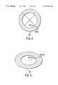
- FIG. 4is an illustration of an embodiment of the present invention.
- separator 201is shaped substantially as an annulus having inner edge 201 a and outer edge 201 b .
- the annulusis circular, with the inner edge and outer edge being concentric.
- an annulustypically connotes a shape formed by concentric circles, for the purposes of this invention, an annulus is defined as any shape that has an inner and outer edge.
- the annular width of separator 201must be sufficient to separate coils 104 and 106 .
- the separatormust have an outer diameter, measured at the outer edge, of at least 5 centimeters.
- radial distancescan be measured from the center of the circle. If the separator or annulus is not circular, however, the radial distance can be measured from any point fixed within the inner edge.
- FIG. 5is an illustration of an embodiment of the present invention.
- separator 301is shaped substantially as an annulus having inner edge 301 a and outer edge 301 b .
- the annulusis oval, with inner edge 301 a and outer edge 301 b being concentric.
- the annular width of separator 301is defined as the distance between inner edge 301 a and outer edge 301 b , both as measured from some point within inner edge 301 a .
- the point inside inner edge 301 ahappens to be the center of the oval, but any point could have been used to measure the distance.
- the tolerances of the gasketare very important to capture the fiber in the bin on the fiber tray.
- the tolerance of the inner edgeis +0.004 inches and ⁇ 0.000 inches
- the tolerance of the outer edgeis +0.000 inches and ⁇ 0.004 inches.
- TYVEKTMOne material for constructing a separator of any shape is TYVEKTM.
- TYVEKTMis spunbonded olefin, a nonwoven material created by DuPont from 100% high density polyethylene (HDPE).
- HDPEhigh density polyethylene
- Tyvekis thin, strong, light weight, machines well, and does not collect an undue amount of static electricity.
- Other materials having properties similar to TYVEKTMcan also be used.
- a thickness of the separator in one embodimentis 0.008 inches.
- the inner edge of the separator that is to fit snugly over the spoolshould have a radius of curvature of no less than 3 cm (approximately 1.5 inches). Gaskets can be made to accommodate any radius greater than 3.0 cm so as not to exceed the maximum bend radius, because any bending of fiber below this accepted radius will shorten the life of the fiber, or may adversely affect the propagation characteristics of the optical fiber.
- FIG. 6is a flow chart for stacking fiber in accordance with an embodiment of the present invention.
- a first optical fiberis wound around the spool.
- the separatoris placed coaxially with the spool next to the first optical fiber.
- the second optical fiberis wound around the spool such that the separator is disposed on the spool between the first optical fiber and the second optical fiber.
- the separatorcan be fit snugly over the spool to leave little room for the fibers to migrate to the other side of the separator.
- the second optical fibercan be placed to abut the separator so as to minimize the size spool necessary.
Landscapes
- Physics & Mathematics (AREA)
- General Physics & Mathematics (AREA)
- Optics & Photonics (AREA)
- Light Guides In General And Applications Therefor (AREA)
Abstract
Description
Claims (8)
Priority Applications (1)
| Application Number | Priority Date | Filing Date | Title |
|---|---|---|---|
| US09/167,579US6263142B1 (en) | 1998-10-07 | 1998-10-07 | Method and apparatus for separating optical fibers |
Applications Claiming Priority (1)
| Application Number | Priority Date | Filing Date | Title |
|---|---|---|---|
| US09/167,579US6263142B1 (en) | 1998-10-07 | 1998-10-07 | Method and apparatus for separating optical fibers |
Publications (1)
| Publication Number | Publication Date |
|---|---|
| US6263142B1true US6263142B1 (en) | 2001-07-17 |
Family
ID=22607941
Family Applications (1)
| Application Number | Title | Priority Date | Filing Date |
|---|---|---|---|
| US09/167,579Expired - LifetimeUS6263142B1 (en) | 1998-10-07 | 1998-10-07 | Method and apparatus for separating optical fibers |
Country Status (1)
| Country | Link |
|---|---|
| US (1) | US6263142B1 (en) |
Cited By (9)
| Publication number | Priority date | Publication date | Assignee | Title |
|---|---|---|---|---|
| US6396679B1 (en)* | 2000-10-18 | 2002-05-28 | Trw Inc. | Single-layer dielectric structure with rounded corners, and circuits including such structures |
| US6682010B2 (en) | 2001-08-13 | 2004-01-27 | Dorsal Networks, Inc. | Optical fiber winding apparatus and method |
| US20080131068A1 (en)* | 2004-03-08 | 2008-06-05 | Adc Telecommunications, Inc. | Fiber Access Terminal |
| US20080232743A1 (en)* | 2007-03-23 | 2008-09-25 | Erik Gronvall | Drop terminal with anchor block for retaining a stub cable |
| US20090046985A1 (en)* | 2007-08-16 | 2009-02-19 | Erik Gronvall | Fiber Optic Enclosure Internal Cable Management |
| US7558458B2 (en) | 2007-03-08 | 2009-07-07 | Adc Telecommunications, Inc. | Universal bracket for mounting a drop terminal |
| US7627222B2 (en) | 2004-11-03 | 2009-12-01 | Adc Telecommunications, Inc. | Fiber drop terminal |
| US7844158B2 (en) | 2007-10-09 | 2010-11-30 | Adc Telecommunications, Inc. | Mini drop terminal |
| US7903923B2 (en) | 2007-10-09 | 2011-03-08 | Adc Telecommunications, Inc. | Drop terminal releasable engagement mechanism |
Citations (4)
| Publication number | Priority date | Publication date | Assignee | Title |
|---|---|---|---|---|
| US5323479A (en)* | 1993-06-17 | 1994-06-21 | Porta Systems Corp. | Package for fiber optic cable |
| US5710855A (en)* | 1994-12-20 | 1998-01-20 | Laser Industries, Ltd. | Package for optical fibers supported in an easily-viewable closed loop |
| US5761368A (en)* | 1995-02-28 | 1998-06-02 | Lucent Technologies Inc. | Storage spool device for optical fibers |
| US5841932A (en)* | 1996-06-21 | 1998-11-24 | Honeywell Inc. | Optical fiber coil and method of winding |
- 1998
- 1998-10-07USUS09/167,579patent/US6263142B1/ennot_activeExpired - Lifetime
Patent Citations (4)
| Publication number | Priority date | Publication date | Assignee | Title |
|---|---|---|---|---|
| US5323479A (en)* | 1993-06-17 | 1994-06-21 | Porta Systems Corp. | Package for fiber optic cable |
| US5710855A (en)* | 1994-12-20 | 1998-01-20 | Laser Industries, Ltd. | Package for optical fibers supported in an easily-viewable closed loop |
| US5761368A (en)* | 1995-02-28 | 1998-06-02 | Lucent Technologies Inc. | Storage spool device for optical fibers |
| US5841932A (en)* | 1996-06-21 | 1998-11-24 | Honeywell Inc. | Optical fiber coil and method of winding |
Cited By (21)
| Publication number | Priority date | Publication date | Assignee | Title |
|---|---|---|---|---|
| US6396679B1 (en)* | 2000-10-18 | 2002-05-28 | Trw Inc. | Single-layer dielectric structure with rounded corners, and circuits including such structures |
| US6682010B2 (en) | 2001-08-13 | 2004-01-27 | Dorsal Networks, Inc. | Optical fiber winding apparatus and method |
| US20080260345A1 (en)* | 2004-03-08 | 2008-10-23 | Adc Telecommunications, Inc. | Fiber access terminal |
| US7400815B2 (en) | 2004-03-08 | 2008-07-15 | Adc Telecommunications, Inc. | Fiber access terminal |
| US20080226252A1 (en)* | 2004-03-08 | 2008-09-18 | Adc Telecommunications, Inc. | Fiber Access Terminal |
| US20080131068A1 (en)* | 2004-03-08 | 2008-06-05 | Adc Telecommunications, Inc. | Fiber Access Terminal |
| US20090297112A1 (en)* | 2004-03-08 | 2009-12-03 | Adc Telecommunications, Inc. | Fiber access terminal |
| US20080260344A1 (en)* | 2004-03-08 | 2008-10-23 | Adc Telecommunications, Inc. | Fiber access terminal |
| US7480437B2 (en) | 2004-03-08 | 2009-01-20 | Adc Telecommunications, Inc. | Fiber access terminal |
| US8363999B2 (en) | 2004-03-08 | 2013-01-29 | Adc Telecommunications, Inc. | Fiber access terminal |
| US7941027B2 (en) | 2004-03-08 | 2011-05-10 | Adc Telecommunications, Inc. | Fiber access terminal |
| US7539388B2 (en) | 2004-03-08 | 2009-05-26 | Adc Telecommunications, Inc. | Fiber access terminal |
| US7539387B2 (en) | 2004-03-08 | 2009-05-26 | Adc Telecommunications, Inc. | Fiber access terminal |
| US7627222B2 (en) | 2004-11-03 | 2009-12-01 | Adc Telecommunications, Inc. | Fiber drop terminal |
| US7558458B2 (en) | 2007-03-08 | 2009-07-07 | Adc Telecommunications, Inc. | Universal bracket for mounting a drop terminal |
| US20080232743A1 (en)* | 2007-03-23 | 2008-09-25 | Erik Gronvall | Drop terminal with anchor block for retaining a stub cable |
| US7512304B2 (en) | 2007-03-23 | 2009-03-31 | Adc Telecommunications, Inc. | Drop terminal with anchor block for retaining a stub cable |
| US20090046985A1 (en)* | 2007-08-16 | 2009-02-19 | Erik Gronvall | Fiber Optic Enclosure Internal Cable Management |
| US7844158B2 (en) | 2007-10-09 | 2010-11-30 | Adc Telecommunications, Inc. | Mini drop terminal |
| US7903923B2 (en) | 2007-10-09 | 2011-03-08 | Adc Telecommunications, Inc. | Drop terminal releasable engagement mechanism |
| US8213761B2 (en) | 2007-10-09 | 2012-07-03 | Adc Telecommunications | Mini drop terminal |
Similar Documents
| Publication | Publication Date | Title |
|---|---|---|
| US6263142B1 (en) | Method and apparatus for separating optical fibers | |
| EP0264941B1 (en) | Spool for holding optical fiber | |
| RU2155154C2 (en) | Reel for optical fiber and case for reel | |
| CA2076280C (en) | Protected optical fiber package | |
| US7457504B2 (en) | Splice tray arrangement | |
| US7533841B1 (en) | Fiber optic cable spool | |
| EP1434088B1 (en) | Roll support member and recording material package employing same | |
| US5791590A (en) | Universal reel | |
| EP2308775B1 (en) | Packing configuration of cable | |
| US5323479A (en) | Package for fiber optic cable | |
| JP2006290619A (en) | Level-wound coil pallet mount and level-wound coil package | |
| WO1996019745A2 (en) | Magazine and cassette for storage of optical fibres | |
| US6263143B1 (en) | Package housing for laser module wound on a spool | |
| US6511010B1 (en) | Optical fiber management installation appliance | |
| KR20010113685A (en) | Optical fibre management | |
| SK6132000A3 (en) | Spool sleeve with a transponder, especially for glass fiber spinning bobbins | |
| US20020153268A1 (en) | Carrier for coiled filaments | |
| US5520353A (en) | Winding hub device for tapes | |
| US6996322B2 (en) | Dispersion compensation module | |
| JP2711683B2 (en) | Tape laminate packaging device and packaging device mounting method | |
| JP4207221B2 (en) | Roll support member and recording material package using the same | |
| CN215246864U (en) | Optical fiber ring packaging tape | |
| CN102135652A (en) | Multi-layer optical fiber collector | |
| JP3396788B2 (en) | Pail winding wire draw-out structure | |
| EP0866016A3 (en) | Tray transfer system and tray storage apparatus |
Legal Events
| Date | Code | Title | Description |
|---|---|---|---|
| AS | Assignment | Owner name:TYCO SUBMARINE SYSTEMS LTD., NEW JERSEY Free format text:ASSIGNMENT OF ASSIGNORS INTEREST;ASSIGNORS:MARDIROSSIAN, HOVHANNES HABIB;BROCKMAN, ROBERT C., III;REEL/FRAME:009517/0476;SIGNING DATES FROM 19981001 TO 19981006 | |
| AS | Assignment | Owner name:TYCOM (US) INC., NEW JERSEY Free format text:CHANGE OF NAME;ASSIGNOR:TYCO SUBMARINE SYSTEMS LTD.;REEL/FRAME:011337/0592 Effective date:20000727 | |
| STCF | Information on status: patent grant | Free format text:PATENTED CASE | |
| FPAY | Fee payment | Year of fee payment:4 | |
| FPAY | Fee payment | Year of fee payment:8 | |
| AS | Assignment | Owner name:TYCO TELECOMMUNICATIONS (US) INC., NEW JERSEY Free format text:CHANGE OF NAME;ASSIGNOR:TYCOM (US) INC.;REEL/FRAME:024213/0432 Effective date:20020105 Owner name:TYCO TELECOMMUNICATIONS (US) INC.,NEW JERSEY Free format text:CHANGE OF NAME;ASSIGNOR:TYCOM (US) INC.;REEL/FRAME:024213/0432 Effective date:20020105 | |
| FPAY | Fee payment | Year of fee payment:12 |