US6263094B1 - Acoustic data acquisition/playback system and method - Google Patents
Acoustic data acquisition/playback system and methodDownload PDFInfo
- Publication number
- US6263094B1 US6263094B1US09/285,831US28583199AUS6263094B1US 6263094 B1US6263094 B1US 6263094B1US 28583199 AUS28583199 AUS 28583199AUS 6263094 B1US6263094 B1US 6263094B1
- Authority
- US
- United States
- Prior art keywords
- acoustic data
- data
- acoustic
- nonvolatile memory
- signal processing
- Prior art date
- Legal status (The legal status is an assumption and is not a legal conclusion. Google has not performed a legal analysis and makes no representation as to the accuracy of the status listed.)
- Expired - Fee Related
Links
Images


Classifications
- G—PHYSICS
- G01—MEASURING; TESTING
- G01S—RADIO DIRECTION-FINDING; RADIO NAVIGATION; DETERMINING DISTANCE OR VELOCITY BY USE OF RADIO WAVES; LOCATING OR PRESENCE-DETECTING BY USE OF THE REFLECTION OR RERADIATION OF RADIO WAVES; ANALOGOUS ARRANGEMENTS USING OTHER WAVES
- G01S7/00—Details of systems according to groups G01S13/00, G01S15/00, G01S17/00
- G01S7/52—Details of systems according to groups G01S13/00, G01S15/00, G01S17/00 of systems according to group G01S15/00
- G01S7/52017—Details of systems according to groups G01S13/00, G01S15/00, G01S17/00 of systems according to group G01S15/00 particularly adapted to short-range imaging
- G01S7/52023—Details of receivers
- G01S7/52025—Details of receivers for pulse systems
- G—PHYSICS
- G01—MEASURING; TESTING
- G01S—RADIO DIRECTION-FINDING; RADIO NAVIGATION; DETERMINING DISTANCE OR VELOCITY BY USE OF RADIO WAVES; LOCATING OR PRESENCE-DETECTING BY USE OF THE REFLECTION OR RERADIATION OF RADIO WAVES; ANALOGOUS ARRANGEMENTS USING OTHER WAVES
- G01S7/00—Details of systems according to groups G01S13/00, G01S15/00, G01S17/00
- G01S7/52—Details of systems according to groups G01S13/00, G01S15/00, G01S17/00 of systems according to group G01S15/00
- G01S7/52017—Details of systems according to groups G01S13/00, G01S15/00, G01S17/00 of systems according to group G01S15/00 particularly adapted to short-range imaging
- G01S7/52023—Details of receivers
- G01S7/52034—Data rate converters
- G—PHYSICS
- G01—MEASURING; TESTING
- G01S—RADIO DIRECTION-FINDING; RADIO NAVIGATION; DETERMINING DISTANCE OR VELOCITY BY USE OF RADIO WAVES; LOCATING OR PRESENCE-DETECTING BY USE OF THE REFLECTION OR RERADIATION OF RADIO WAVES; ANALOGOUS ARRANGEMENTS USING OTHER WAVES
- G01S7/00—Details of systems according to groups G01S13/00, G01S15/00, G01S17/00
- G01S7/52—Details of systems according to groups G01S13/00, G01S15/00, G01S17/00 of systems according to group G01S15/00
- G01S7/52017—Details of systems according to groups G01S13/00, G01S15/00, G01S17/00 of systems according to group G01S15/00 particularly adapted to short-range imaging
- G01S7/52023—Details of receivers
- G01S7/52025—Details of receivers for pulse systems
- G01S7/52026—Extracting wanted echo signals
Definitions
- the present inventiongenerally relates to ultrasound imaging systems, and more particularly, to an acoustic data acquisition/playback system and method for capturing raw acoustic data, at any stage of processing along a signal processing pipeline associated with the ultrasound imaging system (preferably before the data is substantially modified), and allowing subsequent substantially real time (as if the imaged body were present) playback and manipulation of images during playback.
- an ultrasound imaging systemwhen used in a medical application for imaging a patient's body, the ultrasound imaging system is operated by a medical technician to acquire and record (e.g., tape) pertinent images of the body, while the doctor is not present to provide input as to the control settings of the system. Then, at a later time, the images are reviewed by the doctor who diagnoses the patient.
- the imagesare usually stored by the ultrasound imaging system as a video signal, or after the acoustic data has been fully processed and compressed by various signal processing stages and has reached the video stage within the signal processing pipeline associated with the ultrasound imaging system.
- the video signalis essentially comprised of a single or multiple planes of black and white picture elements (pixels) and/or color pixels.
- a significant limitation of the foregoing methodologyis that much of the information associated with the original ultrasound signal is not preserved, as the acoustic data has been processed by various mechanisms, such as filters, mixers, nonlinear transformations, compression mechanisms, etc., along the signal processing pipeline. Thus, when the images are reviewed, no additional or alternative signal processing may be performed upon the images by the doctor, and the patient is typically not available for more imaging sessions with the doctor.
- Vingmed SD 100/200is a doppler-type system that is manufactured by Vingmed Corporation, U.S.A.
- the Vingmed SD 100/200contains a frequency modulated (FM) video store capability, which provides for the storage and playback of baseband doppler audio.
- FMfrequency modulated
- This signalin the audio domain, is arguably analogous to visual information in the video domain.
- the stored signalis in the post-processed format, or the format in which it is presented to the user.
- Raw acoustic datais not preserved, and thus, additional and alternative signal processing of the ultrasound data cannot be performed. Only the stored baseband audio signal is available to the replay device.
- SONOSTM 5500Another example of a commercially available ultrasound imaging system is the SONOSTM 5500, which is manufactured by the Hewlett-Packard Company, USA. Hewlett-Packard's SONOS 5500 provides a slow motion video feature, called the “acoustic quick review” or just “quick review,” which can review acoustic data in slow motion from the SONOS 5500 system. However, the information is stored to non-volatile memory as video pixel data, and is injected back into the system at the video stage of the system, which does not permit additional or alternate signal processing to be performed on the image data.
- the present inventionprovides an acoustic data acquisition/playback system and method for enabling acquisition of acoustic data from an ultrasound imaging system and subsequent substantially real time playback of the acoustic data.
- Acoustic datais acquired at a particular data rate from a signal processing pipeline associated with an ultrasound imaging system during an image acquisition session wherein the acoustic data is produced by exposing a body to ultrasound signals.
- the acquired datais preferably acquired early in the pipeline so that it is completely raw, but it could be partially processed.
- Raw data or near raw dataallows for later signal processing.
- the acoustic datais stored during the session in a nonvolatile memory, which can optionally be removable.
- the acoustic datais introduced into a signal processing system (the same ultrasound imaging system or a different system) from the nonvolatile memory at approximately the particular rate that the data was acquired or at a higher data rate, in order to produce an image in real time for a reviewer that can be modified by the reviewer by further selective processing, if desired.
- a signal processing systemthe same ultrasound imaging system or a different system
- the systemincludes an interface having an input and an output.
- the input and outputare connectable to a signal processing pipeline associated with the ultrasound imaging system (or a different reviewing system) at essentially any point along the pipeline after the digital-to-analog conversion and prior to the conversion to video pixel data.
- the systemalso includes a nonvolatile memory, which can optionally be removable, for storing the acquired data.
- a controllerfor example, a processor operating pursuant to software in the system, which is in electrical communication with the interface and the nonvolatile memory, is designed to selectively control the interface to acquire ultrasound data samples via the input and store the data samples in the nonvolatile memory.
- a suitable graphical user interface or other input schememay be implemented to permit a user to advise the controller as to which data to acquire on a display screen, during the imaging session.
- the controllercan read the ultrasound samples from the nonvolatile memory and communicate the ultrasound samples to the output of the interface at approximately the same or greater than the data rate that the data was acquired at the input of the interface.
- the outputcan be connected to the same acquiring system or to another system for permitting review and processing of the acoustic data.
- the systemmay be provided with a removable nonvolatile memory for transporting the acquired acoustic data from one system to another.
- An advantage of the inventionis that it allows real time playback of previously acquired acoustic data, enabling a reviewer, such as a doctor, to selectively perform additional and/or alternative signal processing upon the acoustic data at a later time.
- Another advantage of the inventionis that it permits re-injection of raw or partially processed acoustic data (e.g., RF, IF, pre-video, etc.) into the signal processing pipeline of the ultrasound imaging system that acquired the acoustic data or into a separate different reviewing system, perhaps another ultrasound imaging system or merely a computer-based viewing system, which matches or exceeds the processing capability of the acquiring system.
- raw or partially processed acoustic datae.g., RF, IF, pre-video, etc.
- Another advantage of the inventionis that when the acoustic data is reinjected, the data rate is at or near the actual rate at which the data was acquired. This effectively simulates the presence of the insonified target. It allows the reviewer of the ultrasound data to change and manipulate the signal processing parameters which the acquiring system can change, and to see the results in real time, as if the insonified target was a source of the data, instead of the storage device.
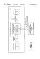
- FIG. 1is a block diagram of the acoustic data acquisition/playback system in accordance with the present invention, which is interconnected with an ultrasound imaging system;
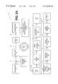
- FIG. 2Ais a block diagram of a possible specific implementation of the ultrasound imaging system of FIG. 1;
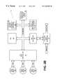
- FIG. 2Bis a block diagram of a possible specific implementation of the acoustic data acquisition/playback system of FIG. 2A;
- FIG. 2Cis a block diagram of a possible specific implementation of the acoustic data interface of FIG. 2B.
- FIG. 3is a schematic diagram of a display screen image on the display of FIGS. 1 and 2, which shows a window controlled by a user for advising the acoustic data acquisition/playback system on which acoustic data to capture.
- FIG. 1is an electrical block diagram showing the acoustic data acquisition/playback system 10 of the present invention interconnected with an ultrasound imaging system 11 , which can be virtually any type of ultrasound imaging system, for example but not limited to, a brightness-mode (B-mode) system, a doppler-based imaging system, a color flow imaging system, etc., as well as a conventional or custom manufactured ultrasound imaging system.
- ultrasound imaging system 11can be virtually any type of ultrasound imaging system, for example but not limited to, a brightness-mode (B-mode) system, a doppler-based imaging system, a color flow imaging system, etc., as well as a conventional or custom manufactured ultrasound imaging system.
- B-modebrightness-mode
- doppler-based imaging systeme.g., a color flow imaging system
- color flow imaging systeme.g., a color flow imaging system
- FIG. 1is an electrical block diagram showing the acoustic data acquisition/playback system 10 of the present invention interconnected with an ultrasound imaging system 11 , which can
- the ultrasound imaging system 11includes a transducer 12 for emitting and receiving ultrasound signals and for acquiring acoustic data 6 for analysis, a signal processing pipeline 13 in electrical communication with the transducer 12 for processing (e.g., filtering, mixing, translating, etc.) and analyzing the acoustic data 6 , and a display 14 in electrical communication with the signal processing pipeline 13 for displaying video picture element (pixel) data 8 , for example, tri-color R, G, B pixel data, to a user of the system 11 .
- pixelvideo picture element
- the acoustic data acquisition/playback system 10is electrically interfaced with the ultrasound imaging system 11 at some point along the signal processing pipeline 13 to enable the acoustic data acquisition/playback system 10 to capture completely raw acoustic data or partially processed acoustic data, denoted by bidirectional reference numeral 7 , for later re-injection and real time playback that allows for additional and/or alternative signal processing by the reviewer, if desired.
- the acoustic data acquisition/playback system 10can be constructed as an integral part of or separable part of the ultrasound imaging system 11 .
- acoustic data along the pipeline 13that can be acquired and re-injected are as follows (nonexhaustive list): completely raw data just after an analog-to-digital conversion; prebeamformed RF data prior to processing by a beamformer; RF intermediately beamformed data; RF filtered data; mixed baseband data, IF data; post-beamformed data, amplitude detected data, post-log data, pre-log data, post-log filtered data, polar coordinate data (R, Theta); orthogonal coordinate data (x, y or x, y, z); and scan converted data that has not yet been processed to video pixel data.
- the acoustic data acquisition/playback system 10is designed to inject the acoustic data back into the same ultrasound imaging system 11 or into a different viewing device or system (which could be another ultrasound imaging system, for example), which matches or exceeds the processing capability of the acquiring system 11 .
- the data rateis approximately at or higher than the actual rate at which the acoustic data 7 was acquired.
- the presence of the insonified targetis effectively simulated at the display 14 . This feature allows the reviewer of the ultrasound data to change and manipulate the signal processing parameters that the acquiring system 11 was capable of changing, and see the results in real time, as if the insonified target was the source of the acoustic data, not a storage device.
- the acoustic data acquisition/playback system 10permits a reviewer of images to adjust at least the following nonexhaustive list of processing parameters while reviewing images, despite the fact that the imaged body may no longer be present or available:
- processingdata means performing one or more of the foregoing operations, or functions, upon the data, including specifically but not limited to those operations shown in the blocks of the block diagram of FIG. 2 A.
- FIG. 2 AA detailed block diagram of a possible example of a specific implementation of the ultrasound imaging system 11 , as interconnected with the acoustic data acquisition/playback system 10 , is shown in FIG. 2 A.
- the acoustic data acquisition/playback system 10 of the present inventionwill be specifically described in detail in the context of an ultrasound imaging system 11 that creates and displays brightness mode (B-Mode) images, or gray-scale images, which are well known in the art, as a nonlimiting example.
- B-Modebrightness mode
- gray-scale imageswhich are well known in the art, as a nonlimiting example.
- the ultrasound imaging system 11includes a conventional central processing unit (CPU) 11 designed to control the operation and timing of the various elements and data flow of the system 11 pursuant to suitable software (not shown for simplicity).
- CPUcentral processing unit
- the ultrasound imaging system 11further includes an ultrasonic transducer 12 configured to emit and receive ultrasound signals, or acoustic energy, respectively to and from an object under test (e.g., a body or a patient when the ultrasound imaging system 11 is used in the context of a medical application).
- an ultrasonic transducer 12configured to emit and receive ultrasound signals, or acoustic energy, respectively to and from an object under test (e.g., a body or a patient when the ultrasound imaging system 11 is used in the context of a medical application).
- an object under teste.g., a body or a patient when the ultrasound imaging system 11 is used in the context of a medical application.
- Many types of transducers 12are known in the art and are suited for use in connection with the present invention.
- the transducer 12comprises an array of elements typically made of a piezoelectric material, for example but not limited to, crystal. Each element is voltage biased and supplied with an electrical pulse or other suitable electrical waveform, causing the elements to collectively propagate an ultrasound pressure wave into the object under test. Moreover, in response thereto, one or more echoes are emitted by the object under test and are received by the transducer 12 , which transforms the echoes into an electrical signal for further processing.
- the array of elements associated with the transducer 13enable a beam, emanating from the transducer array, to be steered (during transmit and receive modes) through the object by shifting the phase (introducing a time delay) of the electrical pulses/biasing signals supplied to the separate elements.
- an analog waveformis communicated to each transducer element, thereby causing a pulse to be selectively propagated in a particular direction, like a beam, through the object.
- an analog waveformis received at each transducer element at each beam position.
- Each analog waveformessentially represents a succession of echoes received by the transducer element over a period of time as echoes are received along the single beam through the object.
- the entire set of analog waveformsrepresents an acoustic line, and the entire set of acoustic lines represents a single view, or image, of an object and is referred to as a frame.
- a transmit pulser 15is electrically connected to the transducer and generates electrical pulses 16 that are periodically communicated to the array of elements of the transducer 12 , causing the transducer elements to emit ultrasound signals into the object under test of the nature described previously.
- the transmit pulser 15typically provides separation between the pulse transmissions to enable the transducer 12 to receive echoes from the object during the period therebetween and forwards them onto a set of parallel analog preamplifiers 18 .
- the plurality of preamplifiers 18receives analog electrical echo waveforms 17 from the transducer 12 that are generated by echoes emitted from the object under test. More specifically, each preamplifier 18 receives an analog electrical echo waveform from a corresponding transducer element for each acoustic line. Moreover, the set of preamplifiers 18 receives a series of waveform sets, one set for each separate acoustic line, in succession over time and processes the waveforms in a pipeline processing manner. The set of preamplifiers 18 is configured to amplify the echo waveforms 17 to provide amplified echo waveforms 19 in order to enable further signal processing, as described hereafter. Because the ultrasound signals received by the transducer 12 are of low power, the set of preamplifiers 18 should be of sufficient quality that excessive noise is not generated in the process.
- a plurality of parallel analog-to-digital converters (ADC) 22are connected respectively to the plurality of preamplifiers 18 , as shown in FIG. 1 .
- Each of the ADCs 22is configured to convert its respective analog echo waveform 19 into a digital echo waveform 23 comprising a number of discrete location points (hundreds to thousands; corresponds with depth and may be a function of ultrasound transmit frequency) with respective quantized instantaneous signal levels, as is well known in the art.
- this conversionoften occurred later in the signal processing steps, but now, many of the logical functions that are performed on the ultrasonic signals can be digital, and hence, the conversion is preferred at an early stage in the signal processing process.
- the plurality of ADCs 22receive a series of waveforms for separate acoustic lines in succession over time and processes the data in a pipeline processing manner.
- the systemmay process signals at a clock rate of 40 MHz with a B-mode frame rate of 100 Hz.
- a beamformer 24is connected to the ADCs 22 and is designed to receive the multiple digital echo waveforms 23 (corresponding with each transducer element) from the ADCs 22 and combine them to form a single acoustic line 26 .
- the beamformer 24delays the separate echo waveforms 23 by different amounts of time and then adds the delayed waveforms together, in order to create a composite digital RF acoustic line 26 .
- the foregoing delay and sum beamforming processis well known in the art.
- the beamformer 24receives a series of data collections for separate acoustic lines in succession over time and processes the data in a pipeline processing manner.
- the acoustic data acquisition/playback system 10is connected to the beamformer 24 to received the beamformed data 25 .
- the system 10is designed to capture a portion (denoted by reference numeral 96 in FIG. 3) of the beamformed acoustic data 25 for later re-injection and real time playback that allows for additional and/or alternative signal processing by the reviewer, if desired.
- the acoustic data acquisition/playback system 10is designed to inject the acoustic data back into the ultrasound imaging system 11 , specifically, into the TGC's 27 , or into a different viewing device or system (which could be another ultrasound imaging system, for example), which matches or exceeds the processing capability of the acquiring system 11 , through an optional exterior port situated on the system 10 or system 11 .
- the data rateis at or near the actual rate at which the acoustic data was acquired.
- the acoustic data acquisition/playback system 10may store the acquired acoustic data on a transportable nonvolatile memory, which can be read by another system for permitting the reviewing process.
- a reviewercan selectively process the acoustic data in any manner desired.
- the beamformed acoustic data 26 from the system 10is passed through one or more time-gain compensators (TGCs) 27 , which are known in the art and which are designed to progressively increase the gain during each acoustic line, thereby reducing the dynamic range requirements on subsequent processing stages.
- TGCstime-gain compensators
- a radio frequency (RF) filter 28is connected to the acoustic data acquisition/playback system 10 and is configured to receive and process digital acoustic lines in succession.
- the RF filter 28is configured to receive each digital acoustic line 26 , to filter it using a bandpass filtering scheme, and to produce a filtered digital acoustic line 33 .
- a mixer 29is connected to the RF filter 28 , as illustrated, and is designed to process each digital acoustic line 33 in pipeline manner.
- the mixer 29is configured to combine the filtered digital acoustic line 33 from the RF filter 28 with a local oscillator signal (not shown for simplicity) in order to ultimately produce a baseband digital acoustic line 32 .
- the local oscillator signalis a complex signal, having an in-phase signal (real) and a quadrature phase signal (imaginary) that are ninety degrees out of phase.
- the result of the operationproduces sum and difference frequency signals.
- the sum frequency signalis filtered out, leaving the difference frequency signal, which is a complex signal at near zero frequency (near DC).
- a complex signalis desired in order to follow direction of movement of parts imaged in the object under test, and to allow accurate, wide bandwidth amplitude detection.
- An amplitude detector 34receives and processes, in pipeline manner, the complex baseband digital acoustic lines 32 from the mixer 29 . For each, the amplitude detector 34 analyzes the envelope of the baseband digital acoustic line 32 to determine the magnitude of signal intensity at each point along the acoustic line and produces an amplitude-detected digital acoustic line 34 . Mathematically, this means that the amplitude detector 34 determines the magnitude of each phasor (distance to origin) corresponding with each point along the acoustic line 32 .
- a log mechanism 38receives the amplitude-detected digital acoustic lines 36 , in pipeline processing manner, from the amplitude detector 34 and compresses the dynamic range of the data by computing the mathematical logarithm (log) of each line 36 to produce a compressed digital acoustic line 39 for further processing.
- Implementation of the log functionenables a more realistic view, ultimately on the display, of the change in brightness corresponding to the ratio of echo intensities.
- a post-log filter 41is connected to the log mechanism 38 and is configured to receive the compressed digital acoustic lines 39 in pipeline fashion and to filter the high frequencies associated with the compressed digital acoustic lines 39 .
- the primary purpose for the low-pass post-log filter 41is to enhance the quality of the ultimate display image.
- the low-pass post-log filter 41softens the speckle in the displayed image.
- the low-pass post-log filter 41can also be configured to perform anti-aliasing.
- the low-pass filter 41can be designed to essentially trade spatial resolution for gray-scale resolution.
- An acoustic memory 45receives the filtered digital acoustic lines 43 from the low-pass post-log filter 41 .
- the acoustic memory 45is configured to accumulate acoustic lines of data over time.
- the acoustic lines 43can be defined within a two (2D) or three (3D) dimensional space, typically a 2D or 3D polar coordinate system, respectively.
- a scan converter 48is connected to the acoustic memory 45 and is designed to convert the data 46 from the acoustic memory 45 from one coordinate system to another in order to produce pixels for display.
- the scan converter 48processes the data in the acoustic memory 45 once an entire data frame (set of all acoustic lines in a single view, or image/picture to be displayed) has been accumulated by the acoustic memory 45 . If two-dimensional (2D) data, then the acoustic memory 45 receives and stores 2D data, typically in defined in polar coordinates, and the scan converter 48 converts the 2D polar coordinate data into 2D rectangular (orthogonal) data capable of raster scan on a raster scan display. If three-dimensional (3D), then the scan conversion is more complicated.
- the acoustic memory 45receives and stores 3D data, and the scan converter 48 renders and scan converts it, i.e., converts it into a 2D view from an appropriate vantage point that is capable of being raster scanned by a display.
- the scan converter 48outputs picture elements (pixels) 51 for storage and/or display.
- a video memory 52also referred to conventionally as a frame buffer, stores the pixel data 51 from the scan converter 48 .
- the video memory 52typically a species of RAM, makes the data readily available to the display 14 for viewing by a user/operator.
- the display 14is preferably a conventional display device that is in electrical communication with the video memory and is configured to periodically retrieve the pixel data 51 from the video memory 52 and drive a suitable screen for viewing of the ultrasound image by a user/operator.
- FIG. 2 BAn example of a possible specific implementation of the acoustic data acquisition/playback system 10 (FIGS. 1 and 2A) is shown by way of a block diagram in FIG. 2 B.
- the acoustic data acquisition/playback system 10is a high performance computer-based system that employs an industry-standard peripheral component interconnect (PCI) architecture.
- PCIperipheral component interconnect
- the system 10employs a local interface in the form of a PCI bus 61 , which interconnects the various elements of the system 10 .
- a local central processing unit (CPU) 62controls the various elements of the system 10 and executes the software and/or firmware of the system 10 .
- a system memory 64for example, a dynamic random access memory (DRAM), stores and makes available control software 66 that is executed by the CPU 62 for achieving the functionality as described herein.
- a nonvolatile removable storage drivefor example, a 100 Mbyte ZIP drive manufactured by and commercially available from lomega, Inc., U.S.A., is connected to the PCI bus 61 to enable RF acoustic data to be removed from the system 10 , if desired.
- An input mechanism 71for example, a keyboard, mouse, etc., is connected to the PCI bus 61 for enabling, among other things, a user to define to the system 10 which data to capture on the display screen associated with the display 14 (FIG. 1) and for enabling a user to manipulate the aforementioned processing parameters during playback.
- An acoustic data interface 72is connected to the PCI bus 61 by way of a PCI interface 74 and is designed to capture incoming acoustic data 25 for storage and to inject acoustic data into the system 11 or another reviewing system.
- a PCI RAID controller 76is connected to the PCI bus 61 and is designed to control a plurality, such as three, of small computer system interface (SCSI) hard drives 78 a - 78 c , each preferably 2 gigabytes in size, for storing acquired acoustic data 79 a - 79 c , respectively.
- SCSIsmall computer system interface
- the CPU 62operating pursuant to the control software 66 , causes at least the following digital sample point information to be stored in the set of SCSI hard drive 78 a - 78 c : (a) a sample rate (and/or sample frequency) indicative of the spacing between samples of acoustic data; (b) for each sample: (1) an amplitude value; (2) a frame identifier, such as a frame number; and (3) an acoustic line identifier, such as an acoustic line number; (c) a start depth (and/or time) of each acoustic line and/or frame; and (d) a stop depth (and/or time) of each acoustic line and/or frame.
- This specific example of the acoustic data acquisition/playback system 10 of FIG. 2Ballows storage and real time retrieval of at least 2.5 minutes of 20 megahertz (MHz) RF data stream from the summing node of a Hewlett-Packard SONOS 5500 ultrasound imaging system. A portion (approximately 2.5 seconds) of this data can be archived and/or transported to another reviewing system using the nonvolatile removable storage drive 68 .
- MHzmegahertz
- the acoustic data interface 72generally includes a buffer/translator 82 and a multiplexor (MUX) 84 .
- the buffer/translator 82receives acoustic data 25 from the beamformer 24 (FIG. 2 A), buffers the acoustic data, and translates the acoustic data into a suitable format, or data structure, for storage by the acoustic data acquisition/playback system 10 (FIG. 2 B).
- the MUX 84receives acoustic data from the beamformer 24 , as indicated by reference arrow 25 b and playback acoustic data 73 b from the PCI interface 74 (FIG. 2 B).
- the MUX 84communicates either the data 25 b or the data 73 b to the TGC's 27 (FIG. 2 A), depending upon the status of a select signal 86 .
- the select signalis generated and communicated from the CPU 9 (FIG. 2A) to the MUX 84 .
- the acoustic data interface 72can acquire data and inject data very quickly, generally at the same data rate at which acoustic data is typically processed in the signal processing pipeline 13 (FIG. 1 ).
- the display screen image 92comprises a trapezoid-like ultrasound image 94 having a curved bottom boundary and skewed linear right and left sides, as shown.
- the shape of the capturing window 96is non-rectangular, that is, it has a curved top boundary, a curved bottom boundary, and generally linear skewed left and right sides as shown in FIG. 3, as the acoustic data at the point of capture will be in polar coordinates, and this geometric configuration is simple to implement and process.
- the capturing window 96which is smaller in size than the ultrasound image 94 , is defined by a user over the ultrasound image 94 via any suitable inputs to one or more input mechanisms 71 (FIG. 2 B).
- the control software 66could be designed to prompt the user to move a mouse cursor to location 97 and either click a mouse button or depress a particular keyboard key and then do the same at location 98 , in order to fully define the periphery and content of the 2D window 96 .
- the control software 66FIG.
- the acoustic data acquisition/playback system 10acquire data at a different stage of processing than is shown and described with respect to FIG. 2 A. More specifically, as examples, the acoustic data acquisition/playback system 10 of FIG. 2A may be situated to and/or connected to acquire and/or inject data at connection 23 after the ADC's 22 , or at connection 31 after the TGC's 27 , or at connection 33 after the RF filter 28 , or at connection 32 after the mixer 29 , or at connection 36 after the amplitude detector 34 , or after the log mechanism 38 , or after the post-log filter 43 , or after the acoustic memory 46 , or after the scan converter 48 . Furthermore, as previously mentioned, the order of some of these processing elements shown in FIG. 2A may be modified, as is known in the art, and it is possible to acquire data at one location and inject it into another different location, in the same machine or a different machine.
- the acoustic data acquisition/playback system 10acquire data at one stage of processing and injecting it into a different processing stage. More specifically, as an example, the acoustic data acquisition/playback system 10 of FIG. 2A may be situated to and/or connected to acquire data at connection 23 after the ADC's 22 and to inject data at connection 33 after the RF filter 28 , or alternatively, acquire data at connection 32 after the mixer 29 and inject data after the log mechanism 38 .
- Yet another species of alternative embodimentsinvolves acquiring the acoustic data from an ultrasound imaging system 11 , processing it with a different signal processing system, for example, a computer system operating pursuant to suitable software, and then introducing the processed acoustic data, at the same point or at a different point in the processing pipeline 13 , in the same acquiring system 11 or 15 in another reviewing system, which can permit review and further processing, if desired, of the acoustic data. More specifically, for instance, with reference to FIG. 1, acoustic data may be acquired after the beamformer 24 at connection 25 in system 11 , then processed relative to the TGC function and the RF filter function in a different signal processing system, and then re-injected at connection 33 to the mixer 29 in the system 11 . Many other alternative configurations along these lines are possible, as will be apparent to one with skill in the art.
Landscapes
- Engineering & Computer Science (AREA)
- Computer Networks & Wireless Communication (AREA)
- Physics & Mathematics (AREA)
- General Physics & Mathematics (AREA)
- Radar, Positioning & Navigation (AREA)
- Remote Sensing (AREA)
- Ultra Sonic Daignosis Equipment (AREA)
Abstract
Description
Claims (20)
Priority Applications (1)
| Application Number | Priority Date | Filing Date | Title |
|---|---|---|---|
| US09/285,831US6263094B1 (en) | 1999-04-02 | 1999-04-02 | Acoustic data acquisition/playback system and method |
Applications Claiming Priority (1)
| Application Number | Priority Date | Filing Date | Title |
|---|---|---|---|
| US09/285,831US6263094B1 (en) | 1999-04-02 | 1999-04-02 | Acoustic data acquisition/playback system and method |
Publications (1)
| Publication Number | Publication Date |
|---|---|
| US6263094B1true US6263094B1 (en) | 2001-07-17 |
Family
ID=23095886
Family Applications (1)
| Application Number | Title | Priority Date | Filing Date |
|---|---|---|---|
| US09/285,831Expired - Fee RelatedUS6263094B1 (en) | 1999-04-02 | 1999-04-02 | Acoustic data acquisition/playback system and method |
Country Status (1)
| Country | Link |
|---|---|
| US (1) | US6263094B1 (en) |
Cited By (39)
| Publication number | Priority date | Publication date | Assignee | Title |
|---|---|---|---|---|
| US20010024477A1 (en)* | 2000-03-14 | 2001-09-27 | Power X Limited | Method for controlling a data transmission pre-emphasis unit and a data transmission system employing the method |
| US6468217B1 (en)* | 2001-07-10 | 2002-10-22 | Koninklijke Philips Electronics N.V. | Method and apparatus for performing real-time storage of ultrasound video image information |
| US6524244B1 (en)* | 1999-09-14 | 2003-02-25 | Ecton Inc. | Medical diagnostic ultrasound system and method |
| US20030195424A1 (en)* | 2000-07-21 | 2003-10-16 | Mcmorrow Gerald J. | System for remote evaluation of ultrasound information obtained by a programmed application-specific data collection device |
| US20030225940A1 (en)* | 2002-05-29 | 2003-12-04 | Oliver Daigle | System and method for acquiring data in a processing unit |
| US20060030775A1 (en)* | 2004-08-04 | 2006-02-09 | Adams Qian Z | Method and system of controlling ultrasound systems |
| US20060058657A1 (en)* | 2004-09-02 | 2006-03-16 | Boston Scientific Corporation | Systems and methods for automatic time-gain compensation in an ultrasound imaging system |
| US20070101816A1 (en)* | 2005-11-04 | 2007-05-10 | Ge Inspection Technologies, Lp | Digital log amplifier for ultrasonic testing |
| US20070232915A1 (en)* | 2006-04-03 | 2007-10-04 | Laurent Pelissier | Ultrasonic imaging system having computer coupled to receive and process raw data |
| US20080146922A1 (en)* | 2006-10-24 | 2008-06-19 | Zonare Medical Systems, Inc. | Control of user interfaces and displays for portable ultrasound unit and docking station |
| US20080165622A1 (en)* | 2007-01-09 | 2008-07-10 | Generalplus Technology Inc. | Audio system and related method integrated with ultrasound communication functionality |
| US20090018443A1 (en)* | 2007-07-12 | 2009-01-15 | Colby Brian V | System for generating multiple beams from a single receive event |
| US20100189329A1 (en)* | 2004-10-07 | 2010-07-29 | Zonare Medical Systems Inc. | Ultrasound Imaging System Parameter Optimization Via Fuzzy Logic |
| US20100305451A1 (en)* | 2009-05-29 | 2010-12-02 | Boston Scientific Scimed, Inc. | Systems and methods for making and using image-guided intravascular and endocardial therapy systems |
| US8002705B1 (en) | 2005-07-22 | 2011-08-23 | Zonaire Medical Systems, Inc. | Continuous transmit focusing method and apparatus for ultrasound imaging system |
| US8401134B1 (en)* | 2009-09-30 | 2013-03-19 | The United States Of America As Represented By The Secretary Of The Navy | Broadband high dynamic range digital receiving system for electromagnetic signals |
| US20130296701A1 (en)* | 2011-11-02 | 2013-11-07 | Seno Medical Instruments, Inc. | Playback mode in an optoacoustic imaging system |
| US20140005544A1 (en)* | 2011-11-02 | 2014-01-02 | Seno Medical Instruments, Inc. | System and method for providing selective channel sensitivity in an optoacoustic imaging system |
| US20140185899A1 (en)* | 2011-10-12 | 2014-07-03 | Seno Medical Instruments, Inc. | System and method for acquiring optoacoustic data and producing parametric maps using interframe persistent artifact removal |
| US8784318B1 (en) | 2005-07-22 | 2014-07-22 | Zonare Medical Systems, Inc. | Aberration correction using channel data in ultrasound imaging system |
| US9060669B1 (en) | 2007-12-20 | 2015-06-23 | Zonare Medical Systems, Inc. | System and method for providing variable ultrasound array processing in a post-storage mode |
| US9451929B2 (en) | 2008-04-17 | 2016-09-27 | Boston Scientific Scimed, Inc. | Degassing intravascular ultrasound imaging systems with sealed catheters filled with an acoustically-favorable medium and methods of making and using |
| US9757092B2 (en) | 2011-11-02 | 2017-09-12 | Seno Medical Instruments, Inc. | Method for dual modality optoacoustic imaging |
| US10026170B2 (en) | 2013-03-15 | 2018-07-17 | Seno Medical Instruments, Inc. | System and method for diagnostic vector classification support |
| US10258241B2 (en) | 2014-02-27 | 2019-04-16 | Seno Medical Instruments, Inc. | Probe adapted to control blood flow through vessels during imaging and method of use of same |
| US10285595B2 (en) | 2011-11-02 | 2019-05-14 | Seno Medical Instruments, Inc. | Interframe energy normalization in an optoacoustic imaging system |
| US10309936B2 (en) | 2013-10-11 | 2019-06-04 | Seno Medical Instruments, Inc. | Systems and methods for component separation in medical imaging |
| US10354379B2 (en) | 2012-03-09 | 2019-07-16 | Seno Medical Instruments, Inc. | Statistical mapping in an optoacoustic imaging system |
| US10349836B2 (en) | 2011-11-02 | 2019-07-16 | Seno Medical Instruments, Inc. | Optoacoustic probe with multi-layer coating |
| US10436705B2 (en) | 2011-12-31 | 2019-10-08 | Seno Medical Instruments, Inc. | System and method for calibrating the light output of an optoacoustic probe |
| US10433732B2 (en) | 2011-11-02 | 2019-10-08 | Seno Medical Instruments, Inc. | Optoacoustic imaging system having handheld probe utilizing optically reflective material |
| US10539675B2 (en) | 2014-10-30 | 2020-01-21 | Seno Medical Instruments, Inc. | Opto-acoustic imaging system with detection of relative orientation of light source and acoustic receiver using acoustic waves |
| US10542892B2 (en) | 2011-11-02 | 2020-01-28 | Seno Medical Instruments, Inc. | Diagnostic simulator |
| US10709419B2 (en) | 2011-11-02 | 2020-07-14 | Seno Medical Instruments, Inc. | Dual modality imaging system for coregistered functional and anatomical mapping |
| US11160457B2 (en) | 2011-11-02 | 2021-11-02 | Seno Medical Instruments, Inc. | Noise suppression in an optoacoustic system |
| US11191435B2 (en) | 2013-01-22 | 2021-12-07 | Seno Medical Instruments, Inc. | Probe with optoacoustic isolator |
| US11287309B2 (en) | 2011-11-02 | 2022-03-29 | Seno Medical Instruments, Inc. | Optoacoustic component utilization tracking |
| US11504097B2 (en) | 2017-09-01 | 2022-11-22 | Clarius Mobile Health Corp. | Systems and methods for acquiring raw ultrasound data from an ultrasound machine using a wirelessly connected device |
| US11633109B2 (en) | 2011-11-02 | 2023-04-25 | Seno Medical Instruments, Inc. | Optoacoustic imaging systems and methods with enhanced safety |
Citations (7)
| Publication number | Priority date | Publication date | Assignee | Title |
|---|---|---|---|---|
| US4167753A (en)* | 1977-08-18 | 1979-09-11 | General Electric Company | Peak detecting digital scan converter |
| US5016641A (en)* | 1989-11-13 | 1991-05-21 | Advanced Technology Laboratories, Inc. | Spectral interpolation of ultrasound Doppler signal |
| US5329929A (en)* | 1991-08-26 | 1994-07-19 | Kabushiki Kaisha Toshiba | Ultrasonic diagnostic apparatus |
| US5373848A (en)* | 1993-08-09 | 1994-12-20 | Hewlett-Packard Company | Ultrasonic time-domain method for sensing fluid flow |
| US5388079A (en)* | 1993-03-26 | 1995-02-07 | Siemens Medical Systems, Inc. | Partial beamforming |
| US6149597A (en)* | 1997-11-26 | 2000-11-21 | Kabushiki Kaisha Toshiba | Diagnostic ultrasound imaging using contrast medium |
| US6171244B1 (en)* | 1997-12-31 | 2001-01-09 | Acuson Corporation | Ultrasonic system and method for storing data |
- 1999
- 1999-04-02USUS09/285,831patent/US6263094B1/ennot_activeExpired - Fee Related
Patent Citations (7)
| Publication number | Priority date | Publication date | Assignee | Title |
|---|---|---|---|---|
| US4167753A (en)* | 1977-08-18 | 1979-09-11 | General Electric Company | Peak detecting digital scan converter |
| US5016641A (en)* | 1989-11-13 | 1991-05-21 | Advanced Technology Laboratories, Inc. | Spectral interpolation of ultrasound Doppler signal |
| US5329929A (en)* | 1991-08-26 | 1994-07-19 | Kabushiki Kaisha Toshiba | Ultrasonic diagnostic apparatus |
| US5388079A (en)* | 1993-03-26 | 1995-02-07 | Siemens Medical Systems, Inc. | Partial beamforming |
| US5373848A (en)* | 1993-08-09 | 1994-12-20 | Hewlett-Packard Company | Ultrasonic time-domain method for sensing fluid flow |
| US6149597A (en)* | 1997-11-26 | 2000-11-21 | Kabushiki Kaisha Toshiba | Diagnostic ultrasound imaging using contrast medium |
| US6171244B1 (en)* | 1997-12-31 | 2001-01-09 | Acuson Corporation | Ultrasonic system and method for storing data |
Cited By (65)
| Publication number | Priority date | Publication date | Assignee | Title |
|---|---|---|---|---|
| US6524244B1 (en)* | 1999-09-14 | 2003-02-25 | Ecton Inc. | Medical diagnostic ultrasound system and method |
| US20010024477A1 (en)* | 2000-03-14 | 2001-09-27 | Power X Limited | Method for controlling a data transmission pre-emphasis unit and a data transmission system employing the method |
| US7006580B2 (en)* | 2000-03-14 | 2006-02-28 | Xyratex Technology Limited | Method for controlling a data transmission pre-emphasis unit and a data transmission system employing the method |
| US20030195424A1 (en)* | 2000-07-21 | 2003-10-16 | Mcmorrow Gerald J. | System for remote evaluation of ultrasound information obtained by a programmed application-specific data collection device |
| US7189205B2 (en)* | 2000-07-21 | 2007-03-13 | Diagnostic Ultrasound Corp. | System for remote evaluation of ultrasound information obtained by a programmed application-specific data collection device |
| US6468217B1 (en)* | 2001-07-10 | 2002-10-22 | Koninklijke Philips Electronics N.V. | Method and apparatus for performing real-time storage of ultrasound video image information |
| US20030225940A1 (en)* | 2002-05-29 | 2003-12-04 | Oliver Daigle | System and method for acquiring data in a processing unit |
| US20060030775A1 (en)* | 2004-08-04 | 2006-02-09 | Adams Qian Z | Method and system of controlling ultrasound systems |
| US7604594B2 (en)* | 2004-08-04 | 2009-10-20 | General Electric Company | Method and system of controlling ultrasound systems |
| US20060058657A1 (en)* | 2004-09-02 | 2006-03-16 | Boston Scientific Corporation | Systems and methods for automatic time-gain compensation in an ultrasound imaging system |
| US7306561B2 (en) | 2004-09-02 | 2007-12-11 | Scimed Life Systems, Inc. | Systems and methods for automatic time-gain compensation in an ultrasound imaging system |
| US8357094B2 (en) | 2004-10-07 | 2013-01-22 | Zonare Medical Systems Inc. | Ultrasound imaging system parameter optimization via fuzzy logic |
| US20100189329A1 (en)* | 2004-10-07 | 2010-07-29 | Zonare Medical Systems Inc. | Ultrasound Imaging System Parameter Optimization Via Fuzzy Logic |
| US9901323B2 (en) | 2005-07-22 | 2018-02-27 | Shenzhen Mindray Bio-Medical Electronics Co., Ltd. | Aberration correction using channel data in ultrasound imaging system |
| US9198636B2 (en) | 2005-07-22 | 2015-12-01 | Shenzhen Mindray Bio-Medical Electronics Co., Ltd. | Continuous transmit focusing method and apparatus for ultrasound imaging system |
| US8784318B1 (en) | 2005-07-22 | 2014-07-22 | Zonare Medical Systems, Inc. | Aberration correction using channel data in ultrasound imaging system |
| US8672846B2 (en) | 2005-07-22 | 2014-03-18 | Zonare Medical Systems, Inc. | Continuous transmit focusing method and apparatus for ultrasound imaging system |
| US8002705B1 (en) | 2005-07-22 | 2011-08-23 | Zonaire Medical Systems, Inc. | Continuous transmit focusing method and apparatus for ultrasound imaging system |
| US7389692B2 (en) | 2005-11-04 | 2008-06-24 | Ge Inspection Technologies, Lp | Digital log amplifier for ultrasonic testing |
| US20070101816A1 (en)* | 2005-11-04 | 2007-05-10 | Ge Inspection Technologies, Lp | Digital log amplifier for ultrasonic testing |
| US8491479B2 (en)* | 2006-04-03 | 2013-07-23 | Ultrasonix Medical Corporation | Ultrasonic imaging system having computer coupled to receive and process raw data |
| US20070232915A1 (en)* | 2006-04-03 | 2007-10-04 | Laurent Pelissier | Ultrasonic imaging system having computer coupled to receive and process raw data |
| US20080146922A1 (en)* | 2006-10-24 | 2008-06-19 | Zonare Medical Systems, Inc. | Control of user interfaces and displays for portable ultrasound unit and docking station |
| US8160276B2 (en)* | 2007-01-09 | 2012-04-17 | Generalplus Technology Inc. | Audio system and related method integrated with ultrasound communication functionality |
| US20080165622A1 (en)* | 2007-01-09 | 2008-07-10 | Generalplus Technology Inc. | Audio system and related method integrated with ultrasound communication functionality |
| US20090018443A1 (en)* | 2007-07-12 | 2009-01-15 | Colby Brian V | System for generating multiple beams from a single receive event |
| US8690782B2 (en)* | 2007-07-12 | 2014-04-08 | Siemens Medical Solutions Usa, Inc. | System for generating multiple beams from a single receive event |
| US9060669B1 (en) | 2007-12-20 | 2015-06-23 | Zonare Medical Systems, Inc. | System and method for providing variable ultrasound array processing in a post-storage mode |
| US10085724B2 (en) | 2007-12-20 | 2018-10-02 | Shenzhen Mindray Bio-Medical Electronics Co., Ltd. | System and method for providing variable ultrasound array processing in a post-storage mode |
| US11103221B2 (en) | 2007-12-20 | 2021-08-31 | Shenzhen Mindray Bio-Medical Electronics Co., Ltd. | System and method for providing variable ultrasound array processing in a post-storage mode |
| US9451929B2 (en) | 2008-04-17 | 2016-09-27 | Boston Scientific Scimed, Inc. | Degassing intravascular ultrasound imaging systems with sealed catheters filled with an acoustically-favorable medium and methods of making and using |
| US20100305451A1 (en)* | 2009-05-29 | 2010-12-02 | Boston Scientific Scimed, Inc. | Systems and methods for making and using image-guided intravascular and endocardial therapy systems |
| US8545412B2 (en) | 2009-05-29 | 2013-10-01 | Boston Scientific Scimed, Inc. | Systems and methods for making and using image-guided intravascular and endocardial therapy systems |
| US8401134B1 (en)* | 2009-09-30 | 2013-03-19 | The United States Of America As Represented By The Secretary Of The Navy | Broadband high dynamic range digital receiving system for electromagnetic signals |
| US9456805B2 (en)* | 2011-10-12 | 2016-10-04 | Seno Medical Instruments, Inc. | System and method for acquiring optoacoustic data and producing parametric maps using interframe persistent artifact removal |
| US11426147B2 (en) | 2011-10-12 | 2022-08-30 | Seno Medical Instruments, Inc. | System and method for acquiring optoacoustic data and producing parametric maps thereof |
| US9724072B2 (en) | 2011-10-12 | 2017-08-08 | Seno Medical Instruments, Inc. | System and method for mixed modality acoustic sampling |
| US10349921B2 (en) | 2011-10-12 | 2019-07-16 | Seno Medical Instruments, Inc. | System and method for mixed modality acoustic sampling |
| US10321896B2 (en) | 2011-10-12 | 2019-06-18 | Seno Medical Instruments, Inc. | System and method for mixed modality acoustic sampling |
| US9792686B2 (en) | 2011-10-12 | 2017-10-17 | Seno Medical Instruments, Inc. | System and method for acquiring optoacoustic data and producing parametric maps using subband acoustic compensation |
| US20140185899A1 (en)* | 2011-10-12 | 2014-07-03 | Seno Medical Instruments, Inc. | System and method for acquiring optoacoustic data and producing parametric maps using interframe persistent artifact removal |
| US10542892B2 (en) | 2011-11-02 | 2020-01-28 | Seno Medical Instruments, Inc. | Diagnostic simulator |
| US10433732B2 (en) | 2011-11-02 | 2019-10-08 | Seno Medical Instruments, Inc. | Optoacoustic imaging system having handheld probe utilizing optically reflective material |
| US11633109B2 (en) | 2011-11-02 | 2023-04-25 | Seno Medical Instruments, Inc. | Optoacoustic imaging systems and methods with enhanced safety |
| US10278589B2 (en) | 2011-11-02 | 2019-05-07 | Seno Medical Instruments, Inc. | Playback mode in an optoacoustic imaging system |
| US10285595B2 (en) | 2011-11-02 | 2019-05-14 | Seno Medical Instruments, Inc. | Interframe energy normalization in an optoacoustic imaging system |
| US20130296701A1 (en)* | 2011-11-02 | 2013-11-07 | Seno Medical Instruments, Inc. | Playback mode in an optoacoustic imaging system |
| US9757092B2 (en) | 2011-11-02 | 2017-09-12 | Seno Medical Instruments, Inc. | Method for dual modality optoacoustic imaging |
| US11287309B2 (en) | 2011-11-02 | 2022-03-29 | Seno Medical Instruments, Inc. | Optoacoustic component utilization tracking |
| US9743839B2 (en)* | 2011-11-02 | 2017-08-29 | Seno Medical Instruments, Inc. | Playback mode in an optoacoustic imaging system |
| US10349836B2 (en) | 2011-11-02 | 2019-07-16 | Seno Medical Instruments, Inc. | Optoacoustic probe with multi-layer coating |
| US11160457B2 (en) | 2011-11-02 | 2021-11-02 | Seno Medical Instruments, Inc. | Noise suppression in an optoacoustic system |
| US20160317034A1 (en)* | 2011-11-02 | 2016-11-03 | Seno Medical Instruments, Inc. | System and method for providing selective channel sensitivity in an optoacoustic imaging system |
| US10517481B2 (en)* | 2011-11-02 | 2019-12-31 | Seno Medical Instruments, Inc. | System and method for providing selective channel sensitivity in an optoacoustic imaging system |
| US10709419B2 (en) | 2011-11-02 | 2020-07-14 | Seno Medical Instruments, Inc. | Dual modality imaging system for coregistered functional and anatomical mapping |
| US20140005544A1 (en)* | 2011-11-02 | 2014-01-02 | Seno Medical Instruments, Inc. | System and method for providing selective channel sensitivity in an optoacoustic imaging system |
| US10436705B2 (en) | 2011-12-31 | 2019-10-08 | Seno Medical Instruments, Inc. | System and method for calibrating the light output of an optoacoustic probe |
| US10354379B2 (en) | 2012-03-09 | 2019-07-16 | Seno Medical Instruments, Inc. | Statistical mapping in an optoacoustic imaging system |
| US11191435B2 (en) | 2013-01-22 | 2021-12-07 | Seno Medical Instruments, Inc. | Probe with optoacoustic isolator |
| US10949967B2 (en) | 2013-03-15 | 2021-03-16 | Seno Medical Instruments, Inc. | System and method for diagnostic vector classification support |
| US10026170B2 (en) | 2013-03-15 | 2018-07-17 | Seno Medical Instruments, Inc. | System and method for diagnostic vector classification support |
| US10309936B2 (en) | 2013-10-11 | 2019-06-04 | Seno Medical Instruments, Inc. | Systems and methods for component separation in medical imaging |
| US10258241B2 (en) | 2014-02-27 | 2019-04-16 | Seno Medical Instruments, Inc. | Probe adapted to control blood flow through vessels during imaging and method of use of same |
| US10539675B2 (en) | 2014-10-30 | 2020-01-21 | Seno Medical Instruments, Inc. | Opto-acoustic imaging system with detection of relative orientation of light source and acoustic receiver using acoustic waves |
| US11504097B2 (en) | 2017-09-01 | 2022-11-22 | Clarius Mobile Health Corp. | Systems and methods for acquiring raw ultrasound data from an ultrasound machine using a wirelessly connected device |
Similar Documents
| Publication | Publication Date | Title |
|---|---|---|
| US6263094B1 (en) | Acoustic data acquisition/playback system and method | |
| CN111356408B (en) | Ultrasound system with high frequency details | |
| KR20080039446A (en) | Ultrasonic Image Processing System and Method for Flow Image Processing Using Real-Time Spatial Synthesis | |
| US20180028153A1 (en) | Ultrasound diagnostic apparatus and ultrasound imaging method | |
| JP2006500146A (en) | Ultrasound imaging system and method for user-guided three-dimensional volume scan sequence | |
| CN101978932B (en) | Ultrasonic observation device | |
| JPH0352034B2 (en) | ||
| JPH08173428A (en) | Method for ultrasonic display of blood flow and apparatus therefor | |
| JP7555719B2 (en) | Ultrasound diagnostic equipment | |
| US6193661B1 (en) | System and method for providing depth perception using single dimension interpolation | |
| JP7273519B2 (en) | Ultrasound diagnostic equipment and learning program | |
| EP3652560B1 (en) | An ultrasound probe and processing method | |
| Martin | B-mode instrumentation | |
| JP6722322B1 (en) | Ultrasonic device and its control program | |
| JP7302972B2 (en) | Ultrasound diagnostic equipment and learning program | |
| US20200022679A1 (en) | Ultrasound diagnostic apparatus and non-transitory storage medium | |
| US12263039B2 (en) | Ultrasonic diagnostic apparatus and ultrasonic diagnostic method | |
| US12059305B2 (en) | Ultrasonic diagnostic device, medical image processing device, and medical image processing method | |
| US20240108314A1 (en) | Ultrasonic diagnostic apparatus and non-transitory computer readable medium | |
| JPH10155794A (en) | Ultrasonic diagnosing apparatus | |
| JPH11206762A (en) | Ultrasonic diagnostic system | |
| Kassem et al. | An efficient SoC dedicated to ultrasonic digital imaging systems | |
| JP2020114293A (en) | Ultrasonic diagnostic device and learning program | |
| JP2003339709A (en) | Doppler signal processing unit and ultrasonic diagnostic apparatus | |
| JP2007159652A (en) | Ultrasonic diagnostic device and image diagnostic device |
Legal Events
| Date | Code | Title | Description |
|---|---|---|---|
| AS | Assignment | Owner name:HEWLETT-PACKARD COMPANY, CALIFORNIA Free format text:ASSIGNMENT OF ASSIGNORS INTEREST;ASSIGNORS:ROSICH, DOUGLAS;HUNT, THOMAS J.;BELANGER, LAURENT;REEL/FRAME:009982/0944;SIGNING DATES FROM 19990324 TO 19990401 | |
| AS | Assignment | Owner name:HEWLETT-PACKARD COMPANY, COLORADO Free format text:MERGER;ASSIGNOR:HEWLETT-PACKARD COMPANY;REEL/FRAME:010759/0049 Effective date:19980520 | |
| AS | Assignment | Owner name:AGILENT TECHNOLOGIES INC, CALIFORNIA Free format text:ASSIGNMENT OF ASSIGNORS INTEREST;ASSIGNOR:HEWLETT-PACKARD COMPANY;REEL/FRAME:010977/0540 Effective date:19991101 | |
| AS | Assignment | Owner name:KONINKLIJKE PHILIPS ELECTRONICS N.V., NETHERLANDS Free format text:ASSIGNMENT OF ASSIGNORS INTEREST;ASSIGNOR:AGILENT TECHNOLOGIES, INC.;REEL/FRAME:014662/0179 Effective date:20010801 | |
| REMI | Maintenance fee reminder mailed | ||
| LAPS | Lapse for failure to pay maintenance fees | ||
| STCH | Information on status: patent discontinuation | Free format text:PATENT EXPIRED DUE TO NONPAYMENT OF MAINTENANCE FEES UNDER 37 CFR 1.362 | |
| FP | Expired due to failure to pay maintenance fee | Effective date:20050717 |