US6262838B1 - Focusing in microscope systems - Google Patents
Focusing in microscope systemsDownload PDFInfo
- Publication number
- US6262838B1 US6262838B1US09/079,790US7979098AUS6262838B1US 6262838 B1US6262838 B1US 6262838B1US 7979098 AUS7979098 AUS 7979098AUS 6262838 B1US6262838 B1US 6262838B1
- Authority
- US
- United States
- Prior art keywords
- microscope
- optical axis
- tiltable
- focusing
- scanning
- Prior art date
- Legal status (The legal status is an assumption and is not a legal conclusion. Google has not performed a legal analysis and makes no representation as to the accuracy of the status listed.)
- Expired - Lifetime
Links
Images


Classifications
- G—PHYSICS
- G01—MEASURING; TESTING
- G01N—INVESTIGATING OR ANALYSING MATERIALS BY DETERMINING THEIR CHEMICAL OR PHYSICAL PROPERTIES
- G01N21/00—Investigating or analysing materials by the use of optical means, i.e. using sub-millimetre waves, infrared, visible or ultraviolet light
- G01N21/62—Systems in which the material investigated is excited whereby it emits light or causes a change in wavelength of the incident light
- G01N21/63—Systems in which the material investigated is excited whereby it emits light or causes a change in wavelength of the incident light optically excited
- G01N21/64—Fluorescence; Phosphorescence
- G01N21/645—Specially adapted constructive features of fluorimeters
- G01N21/6452—Individual samples arranged in a regular 2D-array, e.g. multiwell plates
- B—PERFORMING OPERATIONS; TRANSPORTING
- B01—PHYSICAL OR CHEMICAL PROCESSES OR APPARATUS IN GENERAL
- B01L—CHEMICAL OR PHYSICAL LABORATORY APPARATUS FOR GENERAL USE
- B01L3/00—Containers or dishes for laboratory use, e.g. laboratory glassware; Droppers
- B01L3/02—Burettes; Pipettes
- B01L3/0241—Drop counters; Drop formers
- E—FIXED CONSTRUCTIONS
- E21—EARTH OR ROCK DRILLING; MINING
- E21B—EARTH OR ROCK DRILLING; OBTAINING OIL, GAS, WATER, SOLUBLE OR MELTABLE MATERIALS OR A SLURRY OF MINERALS FROM WELLS
- E21B19/00—Handling rods, casings, tubes or the like outside the borehole, e.g. in the derrick; Apparatus for feeding the rods or cables
- E21B19/08—Apparatus for feeding the rods or cables; Apparatus for increasing or decreasing the pressure on the drilling tool; Apparatus for counterbalancing the weight of the rods
- E21B19/087—Apparatus for feeding the rods or cables; Apparatus for increasing or decreasing the pressure on the drilling tool; Apparatus for counterbalancing the weight of the rods by means of a swinging arm
- G—PHYSICS
- G01—MEASURING; TESTING
- G01N—INVESTIGATING OR ANALYSING MATERIALS BY DETERMINING THEIR CHEMICAL OR PHYSICAL PROPERTIES
- G01N21/00—Investigating or analysing materials by the use of optical means, i.e. using sub-millimetre waves, infrared, visible or ultraviolet light
- G01N21/62—Systems in which the material investigated is excited whereby it emits light or causes a change in wavelength of the incident light
- G01N21/63—Systems in which the material investigated is excited whereby it emits light or causes a change in wavelength of the incident light optically excited
- G01N21/64—Fluorescence; Phosphorescence
- G01N21/645—Specially adapted constructive features of fluorimeters
- G01N21/6456—Spatial resolved fluorescence measurements; Imaging
- G01N21/6458—Fluorescence microscopy
- G—PHYSICS
- G02—OPTICS
- G02B—OPTICAL ELEMENTS, SYSTEMS OR APPARATUS
- G02B21/00—Microscopes
- G02B21/0004—Microscopes specially adapted for specific applications
- G02B21/002—Scanning microscopes
- G02B21/0024—Confocal scanning microscopes (CSOMs) or confocal "macroscopes"; Accessories which are not restricted to use with CSOMs, e.g. sample holders
- G02B21/0036—Scanning details, e.g. scanning stages
- G02B21/0048—Scanning details, e.g. scanning stages scanning mirrors, e.g. rotating or galvanomirrors, MEMS mirrors
- G—PHYSICS
- G02—OPTICS
- G02B—OPTICAL ELEMENTS, SYSTEMS OR APPARATUS
- G02B21/00—Microscopes
- G02B21/0004—Microscopes specially adapted for specific applications
- G02B21/002—Scanning microscopes
- G02B21/0024—Confocal scanning microscopes (CSOMs) or confocal "macroscopes"; Accessories which are not restricted to use with CSOMs, e.g. sample holders
- G02B21/0052—Optical details of the image generation
- G02B21/0072—Optical details of the image generation details concerning resolution or correction, including general design of CSOM objectives
- G—PHYSICS
- G02—OPTICS
- G02B—OPTICAL ELEMENTS, SYSTEMS OR APPARATUS
- G02B21/00—Microscopes
- G02B21/0004—Microscopes specially adapted for specific applications
- G02B21/002—Scanning microscopes
- G02B21/0024—Confocal scanning microscopes (CSOMs) or confocal "macroscopes"; Accessories which are not restricted to use with CSOMs, e.g. sample holders
- G02B21/0052—Optical details of the image generation
- G02B21/0076—Optical details of the image generation arrangements using fluorescence or luminescence
- G—PHYSICS
- G02—OPTICS
- G02B—OPTICAL ELEMENTS, SYSTEMS OR APPARATUS
- G02B21/00—Microscopes
- G02B21/0004—Microscopes specially adapted for specific applications
- G02B21/002—Scanning microscopes
- G02B21/0024—Confocal scanning microscopes (CSOMs) or confocal "macroscopes"; Accessories which are not restricted to use with CSOMs, e.g. sample holders
- G02B21/008—Details of detection or image processing, including general computer control
- G—PHYSICS
- G02—OPTICS
- G02B—OPTICAL ELEMENTS, SYSTEMS OR APPARATUS
- G02B21/00—Microscopes
- G02B21/34—Microscope slides, e.g. mounting specimens on microscope slides
- B—PERFORMING OPERATIONS; TRANSPORTING
- B01—PHYSICAL OR CHEMICAL PROCESSES OR APPARATUS IN GENERAL
- B01J—CHEMICAL OR PHYSICAL PROCESSES, e.g. CATALYSIS OR COLLOID CHEMISTRY; THEIR RELEVANT APPARATUS
- B01J2219/00—Chemical, physical or physico-chemical processes in general; Their relevant apparatus
- B01J2219/00274—Sequential or parallel reactions; Apparatus and devices for combinatorial chemistry or for making arrays; Chemical library technology
- B01J2219/00277—Apparatus
- B01J2219/00351—Means for dispensing and evacuation of reagents
- B01J2219/00364—Pipettes
- B—PERFORMING OPERATIONS; TRANSPORTING
- B01—PHYSICAL OR CHEMICAL PROCESSES OR APPARATUS IN GENERAL
- B01J—CHEMICAL OR PHYSICAL PROCESSES, e.g. CATALYSIS OR COLLOID CHEMISTRY; THEIR RELEVANT APPARATUS
- B01J2219/00—Chemical, physical or physico-chemical processes in general; Their relevant apparatus
- B01J2219/00274—Sequential or parallel reactions; Apparatus and devices for combinatorial chemistry or for making arrays; Chemical library technology
- B01J2219/00277—Apparatus
- B01J2219/00351—Means for dispensing and evacuation of reagents
- B01J2219/00387—Applications using probes
- B—PERFORMING OPERATIONS; TRANSPORTING
- B01—PHYSICAL OR CHEMICAL PROCESSES OR APPARATUS IN GENERAL
- B01J—CHEMICAL OR PHYSICAL PROCESSES, e.g. CATALYSIS OR COLLOID CHEMISTRY; THEIR RELEVANT APPARATUS
- B01J2219/00—Chemical, physical or physico-chemical processes in general; Their relevant apparatus
- B01J2219/00274—Sequential or parallel reactions; Apparatus and devices for combinatorial chemistry or for making arrays; Chemical library technology
- B01J2219/00277—Apparatus
- B01J2219/00497—Features relating to the solid phase supports
- B01J2219/00527—Sheets
- B—PERFORMING OPERATIONS; TRANSPORTING
- B01—PHYSICAL OR CHEMICAL PROCESSES OR APPARATUS IN GENERAL
- B01J—CHEMICAL OR PHYSICAL PROCESSES, e.g. CATALYSIS OR COLLOID CHEMISTRY; THEIR RELEVANT APPARATUS
- B01J2219/00—Chemical, physical or physico-chemical processes in general; Their relevant apparatus
- B01J2219/00274—Sequential or parallel reactions; Apparatus and devices for combinatorial chemistry or for making arrays; Chemical library technology
- B01J2219/00583—Features relative to the processes being carried out
- B01J2219/00585—Parallel processes
- B—PERFORMING OPERATIONS; TRANSPORTING
- B01—PHYSICAL OR CHEMICAL PROCESSES OR APPARATUS IN GENERAL
- B01J—CHEMICAL OR PHYSICAL PROCESSES, e.g. CATALYSIS OR COLLOID CHEMISTRY; THEIR RELEVANT APPARATUS
- B01J2219/00—Chemical, physical or physico-chemical processes in general; Their relevant apparatus
- B01J2219/00274—Sequential or parallel reactions; Apparatus and devices for combinatorial chemistry or for making arrays; Chemical library technology
- B01J2219/00583—Features relative to the processes being carried out
- B01J2219/0059—Sequential processes
- B—PERFORMING OPERATIONS; TRANSPORTING
- B01—PHYSICAL OR CHEMICAL PROCESSES OR APPARATUS IN GENERAL
- B01J—CHEMICAL OR PHYSICAL PROCESSES, e.g. CATALYSIS OR COLLOID CHEMISTRY; THEIR RELEVANT APPARATUS
- B01J2219/00—Chemical, physical or physico-chemical processes in general; Their relevant apparatus
- B01J2219/00274—Sequential or parallel reactions; Apparatus and devices for combinatorial chemistry or for making arrays; Chemical library technology
- B01J2219/00583—Features relative to the processes being carried out
- B01J2219/00596—Solid-phase processes
- B—PERFORMING OPERATIONS; TRANSPORTING
- B01—PHYSICAL OR CHEMICAL PROCESSES OR APPARATUS IN GENERAL
- B01J—CHEMICAL OR PHYSICAL PROCESSES, e.g. CATALYSIS OR COLLOID CHEMISTRY; THEIR RELEVANT APPARATUS
- B01J2219/00—Chemical, physical or physico-chemical processes in general; Their relevant apparatus
- B01J2219/00274—Sequential or parallel reactions; Apparatus and devices for combinatorial chemistry or for making arrays; Chemical library technology
- B01J2219/00583—Features relative to the processes being carried out
- B01J2219/00603—Making arrays on substantially continuous surfaces
- B01J2219/00605—Making arrays on substantially continuous surfaces the compounds being directly bound or immobilised to solid supports
- B01J2219/0061—The surface being organic
- B—PERFORMING OPERATIONS; TRANSPORTING
- B01—PHYSICAL OR CHEMICAL PROCESSES OR APPARATUS IN GENERAL
- B01J—CHEMICAL OR PHYSICAL PROCESSES, e.g. CATALYSIS OR COLLOID CHEMISTRY; THEIR RELEVANT APPARATUS
- B01J2219/00—Chemical, physical or physico-chemical processes in general; Their relevant apparatus
- B01J2219/00274—Sequential or parallel reactions; Apparatus and devices for combinatorial chemistry or for making arrays; Chemical library technology
- B01J2219/00583—Features relative to the processes being carried out
- B01J2219/00603—Making arrays on substantially continuous surfaces
- B01J2219/00605—Making arrays on substantially continuous surfaces the compounds being directly bound or immobilised to solid supports
- B01J2219/00612—Making arrays on substantially continuous surfaces the compounds being directly bound or immobilised to solid supports the surface being inorganic
- B—PERFORMING OPERATIONS; TRANSPORTING
- B01—PHYSICAL OR CHEMICAL PROCESSES OR APPARATUS IN GENERAL
- B01J—CHEMICAL OR PHYSICAL PROCESSES, e.g. CATALYSIS OR COLLOID CHEMISTRY; THEIR RELEVANT APPARATUS
- B01J2219/00—Chemical, physical or physico-chemical processes in general; Their relevant apparatus
- B01J2219/00274—Sequential or parallel reactions; Apparatus and devices for combinatorial chemistry or for making arrays; Chemical library technology
- B01J2219/00583—Features relative to the processes being carried out
- B01J2219/00603—Making arrays on substantially continuous surfaces
- B01J2219/00659—Two-dimensional arrays
- B—PERFORMING OPERATIONS; TRANSPORTING
- B01—PHYSICAL OR CHEMICAL PROCESSES OR APPARATUS IN GENERAL
- B01J—CHEMICAL OR PHYSICAL PROCESSES, e.g. CATALYSIS OR COLLOID CHEMISTRY; THEIR RELEVANT APPARATUS
- B01J2219/00—Chemical, physical or physico-chemical processes in general; Their relevant apparatus
- B01J2219/00274—Sequential or parallel reactions; Apparatus and devices for combinatorial chemistry or for making arrays; Chemical library technology
- B01J2219/00583—Features relative to the processes being carried out
- B01J2219/00603—Making arrays on substantially continuous surfaces
- B01J2219/00677—Ex-situ synthesis followed by deposition on the substrate
- B—PERFORMING OPERATIONS; TRANSPORTING
- B01—PHYSICAL OR CHEMICAL PROCESSES OR APPARATUS IN GENERAL
- B01J—CHEMICAL OR PHYSICAL PROCESSES, e.g. CATALYSIS OR COLLOID CHEMISTRY; THEIR RELEVANT APPARATUS
- B01J2219/00—Chemical, physical or physico-chemical processes in general; Their relevant apparatus
- B01J2219/00274—Sequential or parallel reactions; Apparatus and devices for combinatorial chemistry or for making arrays; Chemical library technology
- B01J2219/0068—Means for controlling the apparatus of the process
- B01J2219/00686—Automatic
- B01J2219/00691—Automatic using robots
- B—PERFORMING OPERATIONS; TRANSPORTING
- B82—NANOTECHNOLOGY
- B82Y—SPECIFIC USES OR APPLICATIONS OF NANOSTRUCTURES; MEASUREMENT OR ANALYSIS OF NANOSTRUCTURES; MANUFACTURE OR TREATMENT OF NANOSTRUCTURES
- B82Y30/00—Nanotechnology for materials or surface science, e.g. nanocomposites
- C—CHEMISTRY; METALLURGY
- C40—COMBINATORIAL TECHNOLOGY
- C40B—COMBINATORIAL CHEMISTRY; LIBRARIES, e.g. CHEMICAL LIBRARIES
- C40B60/00—Apparatus specially adapted for use in combinatorial chemistry or with libraries
- C40B60/14—Apparatus specially adapted for use in combinatorial chemistry or with libraries for creating libraries
- G—PHYSICS
- G01—MEASURING; TESTING
- G01N—INVESTIGATING OR ANALYSING MATERIALS BY DETERMINING THEIR CHEMICAL OR PHYSICAL PROPERTIES
- G01N35/00—Automatic analysis not limited to methods or materials provided for in any single one of groups G01N1/00 - G01N33/00; Handling materials therefor
- G01N35/10—Devices for transferring samples or any liquids to, in, or from, the analysis apparatus, e.g. suction devices, injection devices
- G01N2035/1027—General features of the devices
- G01N2035/1034—Transferring microquantities of liquid
- G01N2035/1037—Using surface tension, e.g. pins or wires
- G—PHYSICS
- G01—MEASURING; TESTING
- G01N—INVESTIGATING OR ANALYSING MATERIALS BY DETERMINING THEIR CHEMICAL OR PHYSICAL PROPERTIES
- G01N35/00—Automatic analysis not limited to methods or materials provided for in any single one of groups G01N1/00 - G01N33/00; Handling materials therefor
- G01N35/10—Devices for transferring samples or any liquids to, in, or from, the analysis apparatus, e.g. suction devices, injection devices
- G01N35/1065—Multiple transfer devices
Definitions
- Focusing mechanisms for microscopesare employed to position the object at the plane of focus of the instrument, to enable the object to be examined, i.e. inspected, illuminated or otherwise acted upon.
- the objectis placed upon a platform that moves laterally relative to the optical axis of the objective, to bring the area of interest of the object into alignment with the optical axis.
- the platformis then raised or lowered (translated) along the optical axis to achieve best focus. If it is necessary to register the optical axis with regions of the object larger than the field of view of the objective lens, the platform and object are further moved laterally in a sequence of steps to view the entire area.
- microscopesare constructed to translate the objective lens or the entire microscope along the optical axis to reach best focus and in some cases the objective lens is moved laterally to bring the optical axis and areas of interest into alignment.
- a known technique for translating the platform and object in the direction of the optical axisemploys a precision dovetail mechanism that is activated by a manual rack and pinion or a motorized lead screw. In many cases this mechanism must be constructed with high accuracy to be capable of micron or sub-micron positional resolution, which results in high cost.
- arrays of fluorescently labeled microorganisms and DNA assaysare created in two dimensional fields.
- the objects to be examined in an arrayare, for example, DNA fragments that have discriminating sequence information.
- Biological laboratorieshave targeted objects for the arrays (e.g., spots of DNA) of diameters of the order of 25 to 250 micron, the spot size depending primarily upon the total number of objects to be represented in the array.
- DNA arraysare typically probed with fluorescently labeled fragments of potentially complementary strands.
- a matchoccurs between a fragment in a deposited spot and a fluorescently labeled fragment probe, hybridization occurs, and a positive “score” can be recorded under fluoroscopic examination.
- fluorescencewhether natural or stimulated by illumination, is a weak signal
- a “score”is identified for DNA spot by the intensity of the fluorescence from the spot compared to reading(s) for the background that directly surrounds the specific spot.
- the large volume of data to be evaluatedalso calls for unattended operation of such instruments upon a sequence of slides, including automatic focusing of the microscope for each slide.
- Microscopes or microscope-like instrumentshave been developed to inspect, illuminate or otherwise treat wide areas, based on scanning principles.
- the imageis constructed electronically from a succession of acquired single picture elements during relative scanning movement between the object and the microscope. Focusing in these instruments is commonly automated, but there are significant economic and operational drawbacks in the systems that have been commercially available.
- a microscope slideis typically a slab of float glass approximately 25 ⁇ 75 mm in x, y dimensions and about 1+0.1/ ⁇ 0.2 mm thick as defined by industrial standard ISO 8037-1-1986E. It is common for microscope slides to be slightly bowed, as they are not very rigid and can be deformed when clamped. In the normal installation of a slide in a microscope, the slide is caused to rest upon a flat surface and is held in place by gently pushing its edges against stops, a technique which alleviates most deformation.
- Other types of substrates for microscopic examinationincluding arrays provided on relatively thin glass cover slips and on plastic substrates, likewise have variation in thickness and are subject to deformation.
- the depth of field (focus tolerance) and the resolution of a given microscopeare inter-related, being defined by the laws of physics. The better the resolution, the smaller is the depth of focus.
- Present day biochip examinationcalls for pixel resolution between 5 and 10 micron which corresponds to a depth of field between approximately 30 and 200 micron, the particular values depending upon the optical configuration and the application. Since the thickness variation of commercial microscope slides is greater than this value, when the slide rests upon its back surface, auto focussing is compulsory.
- automated microscopesemploy dynamic focusing features, i.e. features enabling continual adjustment of focus as scanning of a given slide or object proceeds.
- an algorithmis employed to define focus.
- dynamic systemsanalyze the image acquired through the optical path of the instrument.
- the algorithmis employed under computer control, to cause an element of the system to be raised and lowered as scanning proceeds, to translate the object along the optical axis to achieve focus in a dynamic manner.
- the pattern of raising and loweringis based upon a prescan of the overall object, from which positional information has been stored for use to control focus during the following examination scan.
- instruments that enable dynamic focus adjustment with great precisionrequire great cost.
- the present inventionprovides a novel method and system for focusing a microscope. Though, at its broadest level of generality, it is applicable to all microscopes, it has particular advantage when associated in a system for automatic focusing, and it is presently considered most advantageous when the automatic focusing system is associated with a scanning system in which the object under inspection is translated under either a fixed or moving lens.
- the inventionis especially applicable to instrument systems that operate under computer control such as optical scanners designed for reading biochips. While having a special application in achieving low cost automated scanning, in which focus is established once per slide, it also is advantageous in performing dynamic focus.
- the inventionprovides a simple and low cost technique to bring the relevant surface (typically the top surface) of a microscope slide into the focal plane of a microscope by automatic motions of the instrument.
- the focusing mechanismdoes not employ translation along the optical axis but rather simulates translation by tilting a plane on which the microscope slide is held about a defined hinge axis. It is recognized that tilting a plane about a hinge located at “infinity” can always approximate translation of a small segment of a flat plane; it is now realized that, within the range of practical microscope instrument geometry and capability, rotating a plane about a defined hinge can achieve the desired resolution for a microscope in a practical and low cost manner.
- a planeis fully determined by a line (the defined hinge) and a point.
- the hingedefined to lie in a plane normal to the optical axis of the microscope, focusing is achieved by moving “the point” along a line approximately parallel to the optical axis of the microscope.
- the hinge and the pointcan be set such that a region of the top surface of the slide in registry with the optical axis of the microscope is in focus. If a flat microscope slide of different thickness is later used, adjusting only the movable point can bring the corresponding region of the top surface of that different slide into the focal plane of the objective within practical tolerances. The slide may then be advanced along the plane to bring different regions of the slide into registry with the optical axis.
- Relative location of the hinge and point with respect to the optical axis of the objectiveis advantageously arranged to simulate the action of a lever, in which the movable point is made to move a relatively large amount compared to the resulting motion of the small segment of the plane that lies at the optical axis.
- a comparatively coarse, and therefore low cost, actuatorlocated at the long end of the lever, can be used to bring the surface of interest into focus.
- a signal from a sensorcan be used to servo the actuator so that the desired region of the top surface of the slide will be in the focal plane of the objective, in line with the optical axis.
- a number of methodse.g. optical, capacitive or inductive, can be used to derive a signal to determine the position of the top of the slide.
- a mechanismis driven to press the top of a suitable region of the microscope slide against a buttress to define the desired location of the reference plane.
- the drive mechanism that rotates the plane about the hinge axise.g., a stepper motor driving a worm screw, can be set to rotate the plane about the hinge until the object is so pressed against the buttress that the motor stalls, thus positioning the slide at the known position of the buttress. Later the drive mechanism is retracted the exact magnitude of the known offset of the buttress from the focal plane, to position the object at the focal plane.
- the microscope slideis then translated laterally along the plane to bring the areas of interest into alignment with the optical axis.
- the mounting surface of that mechanismis arranged to be parallel to the plane of lateral transport of the microscope slide.
- a microscope for examination or treatment of an object along an optical axisincluding a tiltable member defining a support plane for the object, the member being mounted to rotate about a defined hinge axis to position the object on the member at the focal plane of the microscope, the hinge axis lying in a plane substantially normal to the optical axis at a distance spaced therefrom, and a drive mechanism for rotating the member about the hinge axis is effective to bring into focus the object supported by the member.
- Preferred embodiments of this aspect of the inventionhave one or more of the following features.
- the drive mechanismis a driver located outwardly along the tiltable member, more distant from the hinge than the position in which the optical axis of the microscope intersects the tiltable member, preferably the distance of the driver from the hinge axis being greater than about twice the distance of the optical axis from the hinge axis.
- the position of the drive mechanismis controlled by an automated control system.
- a buttressis disposed to be engaged by a reference portion of the object to stop the object at a position beyond the focal plane of the microscope, and a control system is arranged to retract the member back from the buttress a preset distance to align the object with the focal plane of the microscope.
- the control systemincludes a detector that senses the relationship of the object relative to the microscope.
- the detectoris an optical, capacitive or inductive position sensor that senses the height of the object.
- the detectorcomprises a light source and a sensor is arranged to determine the height of the object relative to the microscope on the basis of light reflected at an angle from the object.
- a through-the-lens image analyzeris constructed and arranged to enable determination of best focus position.
- the hingeis defined by a pair of spaced apart flexures that support the tiltable member, preferably the flexures being planar spring members.
- a laterally movable carrieris mounted on the tiltable member, the carrier arranged to advance the object, relative to the optical axis.
- the direction of advancesincludes motion in the direction of the radius of the tiltable member.
- a linear guide railis mounted on the tiltable member, the moveable carrier member movable along the guide, the carrier member having a planar surface for supporting a planar object, the planar surface of the carrier member being parallel to the linear guide.
- a driveris arranged to position the carrier member under computer control.
- the microscopeis constructed and arranged to scan in a direction transverse to the radial direction of the tiltable member, preferably the scanning microscope comprising a moving objective microscope, presently preferred being a microscope in which the moving objective is supported upon an oscillating rotary arm that describes an arc generally centered on a radial axis of the tiltable member.
- the objectivehas resolution of between about 5 and 10 micron and a depth of field of between about 30 and 200 micron.
- a controllerconstructed to perform dynamic focus by varying the position of the drive mechanism during scanning, preferably the controller responding to through-the-objective image data, and most preferably including a system constructed to determine best focus data for an array of points during a prescan, to store this data, and to employ this data during microscopic examination of the object.
- Another aspect of the inventionis a microscope for examination of an object along an optical axis, which includes a tiltable member defining a support plane for the object, the member being mounted to rotate about a defined hinge axis to position the object on the member at the focal plane of the microscope, the hinge axis lying in a plane substantially normal to the optical axis at a distance spaced therefrom, and a drive mechanism for rotating the member about the hinge axis is effective to bring into focus the object supported by the member, the microscope constructed and arranged to scan in a direction transverse to the radial direction of the tiltable member, and a laterally movable carrier is mounted on the tiltable member, the carrier arranged to advance the object, relative to the optical axis, in motion in the direction of the radius of the tiltable member.
- the scanning microscopecomprises a moving objective microscope, preferably in which the microscope includes a flying micro-objective lens, and preferably in which the moving objective is supported upon an oscillating rotary arm that describes an arc generally centered on a radial axis of the tiltable member.
- Preferred embodiments of all of the above aspects and features of the inventionare microscopes in which the depth of field is between about 30 and 200 micron, and the drive mechanism is a driver located outwardly along the tiltable member, more distant from the hinge than the position in which the optical axis of the microscope intersects the tiltable member, preferably the distance of the driver from the hinge axis being greater than about twice the distance of the optical axis from the hinge axis.
- a method of microscopic examinationcomprising providing a microscope for examination of an object along an optical axis, the microscope including a tiltable member defining a support plane for the object, the member being mounted to rotate about a defined hinge axis to position the object on the member at the focal plane of the microscope, the hinge axis lying in a plane substantially normal to the optical axis at a distance spaced therefrom, and a drive mechanism for rotating the member about the hinge axis, effective to bring into focus the object supported by the member, and under control of an automated control system, moving the movable member to bring the object into the plane of focus of the microscope.
- Preferred embodiments of this aspect of the inventionhave one or more of the following features.
- the objectcomprises biological material.
- the objectfluoresces and the microscope is constructed to detect such fluorescence, and most preferably the object comprises an ordered array of nucleotides that may fluoresce, preferably the object comprises an ordered array of oligonucleotides or the object comprises an ordered array of deposits of nucleic acid fragments.
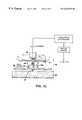
- FIG. 1is a diagrammatic, perspective view of a scanning microscope system incorporating a tilt plane focusing mechanism
- FIG. 1Ais a side view
- FIG. 1Bis a plan view
- FIG. 1Cis a cross sectional view of the mechanism of FIG. 1 .
- FIG. 2is a diagrammatic side view of a scanning microscope system with which the focusing system of FIGS. 1-1C is combined.
- FIGS. 3A and 3Bare diagrams that help define the focus variation caused by the angular oscillating motion of the scanning objective microscope of FIG. 2 associated with the tilt plane focusing mechanism of FIGS. 1-1C.
- FIG. 4illustrates optical height measuring techniques that act upon the top surface of a microscope slide for detecting its position, located as shown in FIGS. 1 and 1B, while
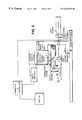
- FIG. 4Ais a diagram of a control system that employs the system of FIG. 4 .
- FIGS. 5A and 5Bare end and side views of a linear stepper motor employed as a pusher mechanism in the system of FIGS. 1-1C and 2 .
- FIG. 6is a diagrammatic illustration of a prescan for 0 dynamic focus
- FIG. 6Ais a similar diagram of the system performing dynamic focus employing stored prescan data.
- the tilt focussing mechanismwill be described as it applies to the presently preferred embodiment, in which is part of a combination that also includes an oscillating flying micro-objective scanning microscope such as shown in FIG. 2 and described in more detail in U.S. patent application 09/045,547, filed Mar. 20, 1998, which is hereby incorporated by reference.
- objective-carrying arm 32rotates in rotary oscillating fashion through an arc of e.g. 60° about rotational axis Z that is normal to the nominal plane of the microscope slide 2 .
- the armcarries a low mass micro-objective lens 14 .
- the optical axis Cat a radial distance from the axis of rotation Z, produces a range of excursion E sufficient to scan the width of the microscope slide 2 .
- the lenstypically has a large numerical aperture.
- An appropriate fixed laser light source and detectorare arranged to communicate with the objective lens along an optical path along the axis of rotation Z of the arm, via folding mirrors carried on the arm.
- the optical axis C of the lensis maintained normal to the nominal surface of the object throughout its scanning motion. While the lens is carried back and forth in its arc, the microscope slide is gradually advanced under the arc of the lens in the direction of axis Y, so that the entire slide is examined in a short time. Dither motion of a mirror in the optical path broadens the curve of the effective arc path of the lens to reduce overlap in successive scans.
- the data for the points of resolutionare recorded throughout the scan of the slide and are employed to form an image by conventional computer techniques.
- the microscope slide 2is held via conventional gentle acting microscope slide holders, not shown, on slide mount platform 12 .
- Platform 12is itself part of moveable carriage 28 , which is mounted to move axially on guide rail 16 , as positioned by motor-driven lead screw 17 .
- Slide mount platform 12is typically a glass plate or an anodized aluminum plate, which is installed under the objective 14 of the oscillating flying objective microscope arm 32 , at a distanced (FIG. 1C) of approximately 1 mm (the nominal thickness of a microscopic slide) away from the focal plane F of the objective.
- rail 16is mounted on hinged carrier plate 26 which is positioned in space on a 3-point mount.
- Two points, H and H′,define hinge axis A.
- the optical axis C of the microscopeis closer to axis A (distance AC), than is the third point B, which lies at distance AB from hinge axis A.
- the three pointsare located in a bi-symmetric fashion with respect to the axis of rotation C of the flying objective arm 32 as shown in the plan view, FIG. 1 B.
- Carriage 28carrying the microscope slide, is motor driven, the motor and lead screw being shown in FIGS. 1A and 1B.
- the top surface T of the slide mount 12is precisely parallel to axis S, the axis of lateral motion of the slide as defined by guide surfaces 16 a of rail 16 . Any deviation is equivalent to defocusing in this embodiment.
- plate 26is flexurally connected to base 40 of the instrument via flexure hinges 18 , here in the form of planar sheets of spring metal that are aligned in the same plane, spaced apart distance d.
- flexure hinges 18here in the form of planar sheets of spring metal that are aligned in the same plane, spaced apart distance d.
- the more remote third mount, B,is raised or lowered by push rod 47 for producing focus as will be described below.
- each flexure 18is secured to carrier plate 26 by a holding device 20 and clamp 22 .
- the other end of each flexure 18is affixed to the instrument base 40 by device 20 via clamp 24 .
- the flexuresestablish the hinge axis in substantial alignment with the top surface of the microscope slide 2 .
- Point Bis acted upon by pusher stepper motor 46 acting through push rod 47 .
- a flat microscope “calibration slide” 2fabricated with great precision, is of uniform and average special thickness of 0.95 mm, the average thickness of conventional slides. It is placed on slide mount 12 and the three points, H, H′ and B are adjusted such that the top surface of slide 2 is set to be at the mid point of the focus range when translated under the objective 14 for all rotated positions of oscillating arm 32 , see arm excursion range E, FIG. 1 B.
- buttress 42(see FIGS. 1A, 1 B) mounted on base 40 (its mounting structure is not shown), is adjusted such that gap 44 , defined between buttress 42 and the top surface T of slide 2 , permits unhindered oscillation of the scanning microscope arm 32 .
- Gap 44is typically 100 micron.
- pusher 46is lowered to create a suitably large gap 44 in excess of 300 micron to prevent interference.
- a reference region of the slideis positioned under buttress 42 , this reference region typically being the frosted section of the microscope slide that is reserved for data recording.
- the pusher 46acting through push rod 47 , raises plate 26 and associated parts so that this region of the top surface of the slide comes in contact with buttress 42 .
- pusher 46is caused to stall when the resistance of buttress 42 is encountered, thus delivering top surface T of the slide to a precisely known reference position.
- pusher 46is then retracted a predetermined amount to bring the top surface T to the known plane of focus F, the relative position of the plane of focus to the buttress 42 having been predetermined.
- the motion of point B along axis P, to achieve a given focus correctionis defined by its distance from the optical axis C of the objective as well as the location of hinge axis A with respect to the objective axis.
- the depth of field requirementtakes into consideration the size of the field of view of the objective lens 14 (which is negligible in the preferred embodiment), the proximity of buttress 42 to optical axis C (a distance which can be made negligible), the Y axis position of the objective lens, which varies with the angular displacement of arm 32 (when the top surface of the slide is not precisely normal to optical axis C), and the position errors of the pusher mechanism 46 .
- FIGS. 3A and 3Billustrate the focus variation dF as a function of angular position of arm 32 over a slide 2 tilted about axis A, in consideration of the variation in thickness permitted for standard microscope slides. It can be seen that:
- R25 mm, the radial distance of objective 14 from the axis of rotation Z of the swing arm 32 .
- This produces focus variation dF+/ ⁇ 6.32 micron or a total of approximately 25% of the depth of field of the objective 14 in the case at hand.
- the miniature flying objective lens 14 in the case at handhas a depth of field of about 50 microns).
- pusher 46is a linear stepper motor, e.g., a Haydon 3646X-V stepper motor available from Haydon Switch and Instrument, Inc. of Waterbury, Conn., having 0.0005 inch (12.5 micron) motion per step.
- a Haydon 3646X-V stepper motoravailable from Haydon Switch and Instrument, Inc. of Waterbury, Conn., having 0.0005 inch (12.5 micron) motion per step.
- the systemis particularly effective for examination of ordered arrays of biological material such as biochips.
- ordered array of oligonucleotidesthat may be hybridized with fluorescently labeled material is inspected.
- the individual specimensmay be present in array densities for instance of 100 to 2000 or more specimens per square centimeter.
- an ordered array of nucleic acid fragmentsis examined, for instance as deposited by the arrayer described in copending U.S. patent application, U.S. Ser. No. 09/006,344, filed Jan. 13, 1998, which is hereby incorporated by reference.
- a number of modalities other than use of the buttress techniquecan be employed to detect the position of the top surface T of the slide or other portions of the moving mechanism.
- the position detector and the pusher actuatormay be linked as a position servomechanism.
- FIG. 4exemplifies other means for detecting the height of the top surface of a slide.
- the system of FIG. 4employs a light emitting diode (LED) and a split photocell detector, according to well known techniques in which light from the LED strikes the surface at an angle and is reflected to the detector, the size of the angle depending upon the proximity of the slide of the LED.
- the detectordetects the position of the top surface essentially along the Z axis, based upon trigonometric considerations.
- the control systemextinguishes the LED during operation of the instrument, to avoid stray light interference.
- capacitive and inductive position sensorsassociated with a capacitive or inductive reference device associated with the slide, can be employed.
- a detector for the height of the top surface of the slide 2feeds the Z position information, i.e. the distance of the slide from the objective, to a controller which, by servo techniques, drives the pusher 46 to bring the slide into the proper position for focus.
- the controlleralso controls the Y stage driver and the galvanometer that drives the oscillating arm 32 .
- the controlleralso manages the collection of data from the objective lens which is input to a computer which receives the detected data and produces the desired image on a monitor.
- the focusing technique describedcan advantageously be used with conventional microscopes and other types of scanning microscopes, preobjective or post objective or translation objective microscopes, etc. It also has application to other microscopic systems, such as laser illumination and laser systems for treating objects of varying dimension.
- FIGS. 1 and 2In cases where higher resolution is desired, thus limiting the depth of field of the microscope, a system similar to that of FIGS. 1 and 2 is provided that implements a dynamic focusing techniques. For example, as depicted in FIG. 6, prescan analysis of the topology of the surface of the microscope slide is performed.
- the slide 2is gradually advanced in direction Y while the flying objective lens 14 is scanned in arcs over the slide by oscillation of arm 32 about axis Z.
- the pusher 46is exercised to dither the height of point B up and down under control of prescan analyzer 80 , thus raising and lowering the object to vary focus.
- the prescan analyzerdetermines the height of best focus for each location. This data is stored, for access during the examination scan.
- One technique for doing thisis by analyzing the frequency content of detected signals for features of the object imaged during prescanning, in relationship to the position of point B that is undergoing dithering.
- Such techniquesare known, see for instance the discussion in U.S. patent application, Ser. No. 09/045,547, filed Mar. 20, 1998, which has been incorporated by reference.
- the position of point B for best focus for a given location on the slidemay be selected as that position in which high frequency content of the signal is maximized.
- a set of datais stored representing the topology of “Best Focus” over the area of the microscope slide.
- the stored prescan datais employed by a dynamic focus controller to elevate and lower point B as the scanning proceeds to bring the respective locations on the slide into best focus.
Landscapes
- Physics & Mathematics (AREA)
- Chemical & Material Sciences (AREA)
- Analytical Chemistry (AREA)
- General Physics & Mathematics (AREA)
- Optics & Photonics (AREA)
- Health & Medical Sciences (AREA)
- Engineering & Computer Science (AREA)
- Life Sciences & Earth Sciences (AREA)
- Nuclear Medicine, Radiotherapy & Molecular Imaging (AREA)
- General Health & Medical Sciences (AREA)
- Immunology (AREA)
- Pathology (AREA)
- Biochemistry (AREA)
- Mining & Mineral Resources (AREA)
- Geology (AREA)
- Clinical Laboratory Science (AREA)
- General Engineering & Computer Science (AREA)
- Mechanical Engineering (AREA)
- Environmental & Geological Engineering (AREA)
- Fluid Mechanics (AREA)
- Computer Vision & Pattern Recognition (AREA)
- Chemical Kinetics & Catalysis (AREA)
- General Life Sciences & Earth Sciences (AREA)
- Geochemistry & Mineralogy (AREA)
- Microscoopes, Condenser (AREA)
Abstract
Description
Claims (42)
Priority Applications (5)
| Application Number | Priority Date | Filing Date | Title |
|---|---|---|---|
| US09/079,790US6262838B1 (en) | 1998-03-20 | 1998-05-15 | Focusing in microscope systems |
| US09/122,216US6269846B1 (en) | 1998-01-13 | 1998-07-24 | Depositing fluid specimens on substrates, resulting ordered arrays, techniques for deposition of arrays |
| US09/500,548US6407858B1 (en) | 1998-05-14 | 2000-02-09 | Focusing of microscopes and reading of microarrays |
| US10/172,787US20030057379A1 (en) | 1998-05-15 | 2002-06-13 | Focusing of microscopes and reading of microarrays |
| US11/145,529US7095032B2 (en) | 1998-03-20 | 2005-06-03 | Focusing of microscopes and reading of microarrays |
Applications Claiming Priority (3)
| Application Number | Priority Date | Filing Date | Title |
|---|---|---|---|
| US09/045,547US6201639B1 (en) | 1998-03-20 | 1998-03-20 | Wide field of view and high speed scanning microscopy |
| US09/079,324US20040126895A1 (en) | 1998-01-13 | 1998-05-14 | Depositing fluid specimens on substrates, resulting ordered arrays, techniques for analysis of deposited arrays |
| US09/079,790US6262838B1 (en) | 1998-03-20 | 1998-05-15 | Focusing in microscope systems |
Related Parent Applications (3)
| Application Number | Title | Priority Date | Filing Date |
|---|---|---|---|
| US09/079,321Continuation-In-PartUS6244349B1 (en) | 1998-05-14 | 1998-05-14 | Circulating nipple and method for setting well casing |
| US09/079,324Continuation-In-PartUS20040126895A1 (en) | 1998-01-13 | 1998-05-14 | Depositing fluid specimens on substrates, resulting ordered arrays, techniques for analysis of deposited arrays |
| PCT/US1999/000730Continuation-In-PartWO1999036760A1 (en) | 1998-01-13 | 1999-01-13 | Depositing fluid specimens on substrates, resulting ordered arrays, techniques for analysis of deposited arrays |
Related Child Applications (4)
| Application Number | Title | Priority Date | Filing Date |
|---|---|---|---|
| US09/079,324Continuation-In-PartUS20040126895A1 (en) | 1998-01-13 | 1998-05-14 | Depositing fluid specimens on substrates, resulting ordered arrays, techniques for analysis of deposited arrays |
| US09/122,216Continuation-In-PartUS6269846B1 (en) | 1998-01-13 | 1998-07-24 | Depositing fluid specimens on substrates, resulting ordered arrays, techniques for deposition of arrays |
| US09/500,548Continuation-In-PartUS6407858B1 (en) | 1998-01-13 | 2000-02-09 | Focusing of microscopes and reading of microarrays |
| US09/500,626Continuation-In-PartUS6472671B1 (en) | 1998-05-15 | 2000-02-09 | Quantified fluorescence microscopy |
Publications (1)
| Publication Number | Publication Date |
|---|---|
| US6262838B1true US6262838B1 (en) | 2001-07-17 |
Family
ID=26722905
Family Applications (1)
| Application Number | Title | Priority Date | Filing Date |
|---|---|---|---|
| US09/079,790Expired - LifetimeUS6262838B1 (en) | 1998-01-13 | 1998-05-15 | Focusing in microscope systems |
Country Status (1)
| Country | Link |
|---|---|
| US (1) | US6262838B1 (en) |
Cited By (47)
| Publication number | Priority date | Publication date | Assignee | Title |
|---|---|---|---|---|
| US20020154396A1 (en)* | 1998-03-20 | 2002-10-24 | Overbeck James W. | Wide field of view and high speed scanning microscopy |
| US20030077633A1 (en)* | 2001-03-30 | 2003-04-24 | Perlegen Sciences, Inc. | Haplotype structures of chromosome 21 |
| US20030079367A1 (en)* | 2001-10-25 | 2003-05-01 | Adriano Troletti | Hair dryer with high handiness |
| US20030099964A1 (en)* | 2001-03-30 | 2003-05-29 | Perlegen Sciences, Inc. | Methods for genomic analysis |
| US6586750B2 (en) | 2000-08-03 | 2003-07-01 | Perlegen Sciences | High performance substrate scanning |
| US20030143751A1 (en)* | 2002-01-31 | 2003-07-31 | Corson John F. | Calibrating array scanners |
| EP1336834A1 (en)* | 2002-02-14 | 2003-08-20 | Daniel Dr. Studer | Device for treating biopsy specimens and method of use thereof |
| US20040023237A1 (en)* | 2001-11-26 | 2004-02-05 | Perelegen Sciences Inc. | Methods for genomic analysis |
| US20040029161A1 (en)* | 2001-08-17 | 2004-02-12 | Perlegen Sciences, Inc. | Methods for genomic analysis |
| US20040053232A1 (en)* | 2001-10-05 | 2004-03-18 | Perlegen Sciences, Inc. | Haplotype structures of chromosome 21 |
| US20040256538A1 (en)* | 2000-05-03 | 2004-12-23 | Allen Olson | Method and apparatus for pre-focus in a linear array based slide scanner |
| US6844965B1 (en)* | 1999-11-29 | 2005-01-18 | Leica Microsystems Heidelberg Gmbh | Apparatus for optical scanning of multiple specimens |
| US20050153349A1 (en)* | 2002-07-31 | 2005-07-14 | Jayati Ghosh | Biopolymer array substrate thickness dependent automated focus-distance determination method for biopolymer array scanners |
| US20050275938A1 (en)* | 2004-06-10 | 2005-12-15 | Olympus Corporation | Microscope illumination intensity measuring device |
| US6985616B2 (en) | 2001-10-18 | 2006-01-10 | Robodesign International, Inc. | Automated verification and inspection device for sequentially inspecting microscopic crystals |
| US20060269450A1 (en)* | 2005-05-27 | 2006-11-30 | Kim Yong M | Sensing apparatus having rotating optical assembly |
| US7169560B2 (en) | 2003-11-12 | 2007-01-30 | Helicos Biosciences Corporation | Short cycle methods for sequencing polynucleotides |
| US20070031056A1 (en)* | 2005-08-02 | 2007-02-08 | Perz Cynthia B | System for and method of focusing in automated microscope systems |
| US7220549B2 (en) | 2004-12-30 | 2007-05-22 | Helicos Biosciences Corporation | Stabilizing a nucleic acid for nucleic acid sequencing |
| US20070205365A1 (en)* | 2006-03-03 | 2007-09-06 | Asbjorn Smitt | Sensing apparatus having optical assembly that collimates emitted light for detection |
| US7297518B2 (en) | 2001-03-12 | 2007-11-20 | California Institute Of Technology | Methods and apparatus for analyzing polynucleotide sequences by asynchronous base extension |
| US20080055405A1 (en)* | 2003-02-05 | 2008-03-06 | Hamamatsu Photonics K.K. | Microscope system and method |
| US7462449B2 (en) | 1999-06-28 | 2008-12-09 | California Institute Of Technology | Methods and apparatuses for analyzing polynucleotide sequences |
| US7476734B2 (en) | 2005-12-06 | 2009-01-13 | Helicos Biosciences Corporation | Nucleotide analogs |
| US7482120B2 (en) | 2005-01-28 | 2009-01-27 | Helicos Biosciences Corporation | Methods and compositions for improving fidelity in a nucleic acid synthesis reaction |
| US20090141126A1 (en)* | 2000-05-03 | 2009-06-04 | Aperio Technologies, Inc. | Fully Automatic Rapid Microscope Slide Scanner |
| US20090203022A1 (en)* | 2008-02-07 | 2009-08-13 | Arizona Board Of Regents For And On Behalf Of Arizona State University | Analysis |
| US7635562B2 (en) | 2004-05-25 | 2009-12-22 | Helicos Biosciences Corporation | Methods and devices for nucleic acid sequence determination |
| US7645596B2 (en) | 1998-05-01 | 2010-01-12 | Arizona Board Of Regents | Method of determining the nucleotide sequence of oligonucleotides and DNA molecules |
| US7666593B2 (en) | 2005-08-26 | 2010-02-23 | Helicos Biosciences Corporation | Single molecule sequencing of captured nucleic acids |
| US20100213063A1 (en)* | 2009-02-09 | 2010-08-26 | Frederic Zenhausern | Analysis |
| USRE42220E1 (en)* | 1999-04-21 | 2011-03-15 | Hamamatsu Photonics K.K. | Microscopy |
| US20110090223A1 (en)* | 2004-05-27 | 2011-04-21 | Aperio Technologies, Inc. | Creating and viewing three dimensional virtual slides |
| US7981604B2 (en) | 2004-02-19 | 2011-07-19 | California Institute Of Technology | Methods and kits for analyzing polynucleotide sequences |
| US8103082B2 (en) | 2000-05-03 | 2012-01-24 | Aperio Technologies, Inc. | Optimizing virtual slide image quality |
| US8199358B2 (en) | 2003-02-28 | 2012-06-12 | Aperio Technologies, Inc. | Digital slide image analysis |
| US8351026B2 (en) | 2005-04-22 | 2013-01-08 | Affymetrix, Inc. | Methods and devices for reading microarrays |
| US8582849B2 (en) | 2000-05-03 | 2013-11-12 | Leica Biosystems Imaging, Inc. | Viewing digital slides |
| US20130321814A1 (en)* | 2012-05-31 | 2013-12-05 | General Electric Company | Systems and methods for screening of biological samples |
| US8705825B2 (en) | 2009-12-11 | 2014-04-22 | Leica Biosystems Imaging, Inc. | Signal to noise ratio in digital pathology image analysis |
| US8743195B2 (en) | 2008-10-24 | 2014-06-03 | Leica Biosystems Imaging, Inc. | Whole slide fluorescence scanner |
| US9096898B2 (en) | 1998-05-01 | 2015-08-04 | Life Technologies Corporation | Method of determining the nucleotide sequence of oligonucleotides and DNA molecules |
| US9235041B2 (en) | 2005-07-01 | 2016-01-12 | Leica Biosystems Imaging, Inc. | System and method for single optical axis multi-detector microscope slide scanner |
| CN106677723A (en)* | 2017-02-21 | 2017-05-17 | 李广连 | A Position Measuring Device for Oil Well Electric Push Rod |
| CN111413339A (en)* | 2016-08-29 | 2020-07-14 | 爱威科技股份有限公司 | Microscopic examination device |
| WO2022000193A1 (en)* | 2020-06-29 | 2022-01-06 | 中国科学院深圳先进技术研究院 | Scanning device |
| IT202200016704A1 (en) | 2022-08-04 | 2024-02-04 | Sunland Optics Srl | GOBO PROJECTOR AND METHOD OF USING A GOBO PROJECTOR |
Citations (8)
| Publication number | Priority date | Publication date | Assignee | Title |
|---|---|---|---|---|
| US4627009A (en) | 1983-05-24 | 1986-12-02 | Nanometrics Inc. | Microscope stage assembly and control system |
| US4688908A (en)* | 1984-10-12 | 1987-08-25 | Vickers Plc | Microscope stage |
| US4832474A (en)* | 1985-02-04 | 1989-05-23 | Olympus Optical Co., Ltd. | Microscope apparatus for examining wafer |
| US4891526A (en) | 1986-12-29 | 1990-01-02 | Hughes Aircraft Company | X-Y-θ-Z positioning stage |
| US5337178A (en) | 1992-12-23 | 1994-08-09 | International Business Machines Corporation | Titlable optical microscope stage |
| US5351925A (en) | 1990-07-18 | 1994-10-04 | Deemed International | Device for supporting and positioning a microscope |
| US5461237A (en)* | 1993-03-26 | 1995-10-24 | Nikon Corporation | Surface-position setting apparatus |
| US5583691A (en) | 1993-12-07 | 1996-12-10 | The Furukawa Electric Co., Ltd. | Multi-axes stage |
- 1998
- 1998-05-15USUS09/079,790patent/US6262838B1/ennot_activeExpired - Lifetime
Patent Citations (8)
| Publication number | Priority date | Publication date | Assignee | Title |
|---|---|---|---|---|
| US4627009A (en) | 1983-05-24 | 1986-12-02 | Nanometrics Inc. | Microscope stage assembly and control system |
| US4688908A (en)* | 1984-10-12 | 1987-08-25 | Vickers Plc | Microscope stage |
| US4832474A (en)* | 1985-02-04 | 1989-05-23 | Olympus Optical Co., Ltd. | Microscope apparatus for examining wafer |
| US4891526A (en) | 1986-12-29 | 1990-01-02 | Hughes Aircraft Company | X-Y-θ-Z positioning stage |
| US5351925A (en) | 1990-07-18 | 1994-10-04 | Deemed International | Device for supporting and positioning a microscope |
| US5337178A (en) | 1992-12-23 | 1994-08-09 | International Business Machines Corporation | Titlable optical microscope stage |
| US5461237A (en)* | 1993-03-26 | 1995-10-24 | Nikon Corporation | Surface-position setting apparatus |
| US5583691A (en) | 1993-12-07 | 1996-12-10 | The Furukawa Electric Co., Ltd. | Multi-axes stage |
Cited By (109)
| Publication number | Priority date | Publication date | Assignee | Title |
|---|---|---|---|---|
| US7312919B2 (en)* | 1998-03-20 | 2007-12-25 | Affymetrix, Inc. | Wide field of view and high speed scanning microscopy |
| US20020154396A1 (en)* | 1998-03-20 | 2002-10-24 | Overbeck James W. | Wide field of view and high speed scanning microscopy |
| US9957561B2 (en) | 1998-05-01 | 2018-05-01 | Life Technologies Corporation | Method of determining the nucleotide sequence of oligonucleotides and DNA molecules |
| US9725764B2 (en) | 1998-05-01 | 2017-08-08 | Life Technologies Corporation | Method of determining the nucleotide sequence of oligonucleotides and DNA molecules |
| US7645596B2 (en) | 1998-05-01 | 2010-01-12 | Arizona Board Of Regents | Method of determining the nucleotide sequence of oligonucleotides and DNA molecules |
| US9540689B2 (en) | 1998-05-01 | 2017-01-10 | Life Technologies Corporation | Method of determining the nucleotide sequence of oligonucleotides and DNA molecules |
| US10208341B2 (en) | 1998-05-01 | 2019-02-19 | Life Technologies Corporation | Method of determining the nucleotide sequence of oligonucleotides and DNA molecules |
| US10214774B2 (en) | 1998-05-01 | 2019-02-26 | Life Technologies Corporation | Method of determining the nucleotide sequence of oligonucleotides and DNA molecules |
| US9458500B2 (en) | 1998-05-01 | 2016-10-04 | Life Technologies Corporation | Method of determining the nucleotide sequence of oligonucleotides and DNA molecules |
| US9212393B2 (en) | 1998-05-01 | 2015-12-15 | Life Technologies Corporation | Method of determining the nucleotide sequence of oligonucleotides and DNA molecules |
| US9096898B2 (en) | 1998-05-01 | 2015-08-04 | Life Technologies Corporation | Method of determining the nucleotide sequence of oligonucleotides and DNA molecules |
| USRE42220E1 (en)* | 1999-04-21 | 2011-03-15 | Hamamatsu Photonics K.K. | Microscopy |
| US7462449B2 (en) | 1999-06-28 | 2008-12-09 | California Institute Of Technology | Methods and apparatuses for analyzing polynucleotide sequences |
| US6844965B1 (en)* | 1999-11-29 | 2005-01-18 | Leica Microsystems Heidelberg Gmbh | Apparatus for optical scanning of multiple specimens |
| US20110141263A1 (en)* | 2000-05-03 | 2011-06-16 | Aperio Technologies, Inc. | Achieving Focus in a Digital Pathology System |
| US9723036B2 (en) | 2000-05-03 | 2017-08-01 | Leica Biosystems Imaging, Inc. | Viewing digital slides |
| US8805050B2 (en) | 2000-05-03 | 2014-08-12 | Leica Biosystems Imaging, Inc. | Optimizing virtual slide image quality |
| US20040256538A1 (en)* | 2000-05-03 | 2004-12-23 | Allen Olson | Method and apparatus for pre-focus in a linear array based slide scanner |
| US8755579B2 (en) | 2000-05-03 | 2014-06-17 | Leica Biosystems Imaging, Inc. | Fully automatic rapid microscope slide scanner |
| US9213177B2 (en) | 2000-05-03 | 2015-12-15 | Leica Biosystems Imaging, Inc. | Achieving focus in a digital pathology system |
| US7978894B2 (en) | 2000-05-03 | 2011-07-12 | Aperio Technologies, Inc. | Fully automatic rapid microscope slide scanner |
| US8731260B2 (en) | 2000-05-03 | 2014-05-20 | Leica Biosystems Imaging, Inc. | Data management in a linear-array-based microscope slide scanner |
| US8582849B2 (en) | 2000-05-03 | 2013-11-12 | Leica Biosystems Imaging, Inc. | Viewing digital slides |
| US8055042B2 (en) | 2000-05-03 | 2011-11-08 | Aperio Technologies, Inc. | Fully automatic rapid microscope slide scanner |
| US9851550B2 (en) | 2000-05-03 | 2017-12-26 | Leica Biosystems Imaging, Inc. | Fully automatic rapid microscope slide scanner |
| US9729749B2 (en) | 2000-05-03 | 2017-08-08 | Leica Biosystems Imaging, Inc. | Data management in a linear-array-based microscope slide scanner |
| US20090141126A1 (en)* | 2000-05-03 | 2009-06-04 | Aperio Technologies, Inc. | Fully Automatic Rapid Microscope Slide Scanner |
| US9521309B2 (en) | 2000-05-03 | 2016-12-13 | Leica Biosystems Imaging, Inc. | Data management in a linear-array-based microscope slide scanner |
| US8103082B2 (en) | 2000-05-03 | 2012-01-24 | Aperio Technologies, Inc. | Optimizing virtual slide image quality |
| US7646495B2 (en) | 2000-05-03 | 2010-01-12 | Aperio Technologies, Inc. | System and computer readable medium for pre-focus of digital slides |
| US9386211B2 (en) | 2000-05-03 | 2016-07-05 | Leica Biosystems Imaging, Inc. | Fully automatic rapid microscope slide scanner |
| US20090303321A1 (en)* | 2000-05-03 | 2009-12-10 | Aperio Technologies, Inc. | System and Computer Readable Medium for Pre-focus of Digital Slides |
| US8385619B2 (en) | 2000-05-03 | 2013-02-26 | Aperio Technologies, Inc. | Fully automatic rapid microscope slide scanner |
| US7893988B2 (en) | 2000-05-03 | 2011-02-22 | Aperio Technologies, Inc. | Method for pre-focus of digital slides |
| US8456522B2 (en) | 2000-05-03 | 2013-06-04 | Aperio Technologies, Inc. | Achieving focus in a digital pathology system |
| US9535243B2 (en) | 2000-05-03 | 2017-01-03 | Leica Biosystems Imaging, Inc. | Optimizing virtual slide image quality |
| US7518652B2 (en)* | 2000-05-03 | 2009-04-14 | Aperio Technologies, Inc. | Method and apparatus for pre-focus in a linear array based slide scanner |
| US6586750B2 (en) | 2000-08-03 | 2003-07-01 | Perlegen Sciences | High performance substrate scanning |
| US7297518B2 (en) | 2001-03-12 | 2007-11-20 | California Institute Of Technology | Methods and apparatus for analyzing polynucleotide sequences by asynchronous base extension |
| US11031098B2 (en) | 2001-03-30 | 2021-06-08 | Genetic Technologies Limited | Computer systems and methods for genomic analysis |
| US20030099964A1 (en)* | 2001-03-30 | 2003-05-29 | Perlegen Sciences, Inc. | Methods for genomic analysis |
| US20030077633A1 (en)* | 2001-03-30 | 2003-04-24 | Perlegen Sciences, Inc. | Haplotype structures of chromosome 21 |
| US6969589B2 (en) | 2001-03-30 | 2005-11-29 | Perlegen Sciences, Inc. | Methods for genomic analysis |
| US20050272086A1 (en)* | 2001-03-30 | 2005-12-08 | Perlegen Sciences, Inc. | Methods for genomic analysis |
| US20060234216A9 (en)* | 2001-03-30 | 2006-10-19 | Perlegen Sciences, Inc. | Haplotype structures of chromosome 21 |
| US7115726B2 (en) | 2001-03-30 | 2006-10-03 | Perlegen Sciences, Inc. | Haplotype structures of chromosome 21 |
| US20110020815A1 (en)* | 2001-03-30 | 2011-01-27 | Nila Patil | Methods for genomic analysis |
| US20080026367A9 (en)* | 2001-08-17 | 2008-01-31 | Perlegen Sciences, Inc. | Methods for genomic analysis |
| US20040029161A1 (en)* | 2001-08-17 | 2004-02-12 | Perlegen Sciences, Inc. | Methods for genomic analysis |
| US20040053232A1 (en)* | 2001-10-05 | 2004-03-18 | Perlegen Sciences, Inc. | Haplotype structures of chromosome 21 |
| US6985616B2 (en) | 2001-10-18 | 2006-01-10 | Robodesign International, Inc. | Automated verification and inspection device for sequentially inspecting microscopic crystals |
| US20030079367A1 (en)* | 2001-10-25 | 2003-05-01 | Adriano Troletti | Hair dryer with high handiness |
| US20040023237A1 (en)* | 2001-11-26 | 2004-02-05 | Perelegen Sciences Inc. | Methods for genomic analysis |
| US7205154B2 (en) | 2002-01-31 | 2007-04-17 | Agilent Technologies, Inc. | Calibrating array scanners |
| US20030143751A1 (en)* | 2002-01-31 | 2003-07-31 | Corson John F. | Calibrating array scanners |
| EP1333102A3 (en)* | 2002-01-31 | 2004-01-02 | Agilent Technologies, Inc. | Calibrating array scanners |
| EP1336834A1 (en)* | 2002-02-14 | 2003-08-20 | Daniel Dr. Studer | Device for treating biopsy specimens and method of use thereof |
| US7361906B2 (en)* | 2002-07-31 | 2008-04-22 | Agilent Technologies, Inc. | Biopolymer array substrate thickness dependent automated focus-distance determination method for biopolymer array scanners |
| US20050153349A1 (en)* | 2002-07-31 | 2005-07-14 | Jayati Ghosh | Biopolymer array substrate thickness dependent automated focus-distance determination method for biopolymer array scanners |
| US8107770B2 (en) | 2003-02-05 | 2012-01-31 | Hamamatsu Photonics K.K. | Microscope system and method |
| US8478073B2 (en) | 2003-02-05 | 2013-07-02 | Hamamatsu Photonics K.K. | Microscope system and method |
| US20080055405A1 (en)* | 2003-02-05 | 2008-03-06 | Hamamatsu Photonics K.K. | Microscope system and method |
| US8780401B2 (en) | 2003-02-28 | 2014-07-15 | Leica Biosystems Imaging, Inc. | Systems and methods for analyzing digital slide images using algorithms constrained by parameter data |
| US8467083B2 (en) | 2003-02-28 | 2013-06-18 | Aperio Technologies, Inc. | Framework for processing the content of a digital image of a microscope sample |
| US8199358B2 (en) | 2003-02-28 | 2012-06-12 | Aperio Technologies, Inc. | Digital slide image analysis |
| US9019546B2 (en) | 2003-02-28 | 2015-04-28 | Leica Biosystems Imaging, Inc. | Image processing of digital slide images based on a macro |
| US9012144B2 (en) | 2003-11-12 | 2015-04-21 | Fluidigm Corporation | Short cycle methods for sequencing polynucleotides |
| US7169560B2 (en) | 2003-11-12 | 2007-01-30 | Helicos Biosciences Corporation | Short cycle methods for sequencing polynucleotides |
| US9657344B2 (en) | 2003-11-12 | 2017-05-23 | Fluidigm Corporation | Short cycle methods for sequencing polynucleotides |
| US7491498B2 (en) | 2003-11-12 | 2009-02-17 | Helicos Biosciences Corporation | Short cycle methods for sequencing polynucleotides |
| US7897345B2 (en) | 2003-11-12 | 2011-03-01 | Helicos Biosciences Corporation | Short cycle methods for sequencing polynucleotides |
| US7981604B2 (en) | 2004-02-19 | 2011-07-19 | California Institute Of Technology | Methods and kits for analyzing polynucleotide sequences |
| US7635562B2 (en) | 2004-05-25 | 2009-12-22 | Helicos Biosciences Corporation | Methods and devices for nucleic acid sequence determination |
| US20110090223A1 (en)* | 2004-05-27 | 2011-04-21 | Aperio Technologies, Inc. | Creating and viewing three dimensional virtual slides |
| US8565480B2 (en) | 2004-05-27 | 2013-10-22 | Leica Biosystems Imaging, Inc. | Creating and viewing three dimensional virtual slides |
| US8923597B2 (en) | 2004-05-27 | 2014-12-30 | Leica Biosystems Imaging, Inc. | Creating and viewing three dimensional virtual slides |
| US9069179B2 (en) | 2004-05-27 | 2015-06-30 | Leica Biosystems Imaging, Inc. | Creating and viewing three dimensional virtual slides |
| US20050275938A1 (en)* | 2004-06-10 | 2005-12-15 | Olympus Corporation | Microscope illumination intensity measuring device |
| US7289265B2 (en) | 2004-06-10 | 2007-10-30 | Olympus Corporation | Microscope illumination intensity measuring device |
| US7220549B2 (en) | 2004-12-30 | 2007-05-22 | Helicos Biosciences Corporation | Stabilizing a nucleic acid for nucleic acid sequencing |
| US7482120B2 (en) | 2005-01-28 | 2009-01-27 | Helicos Biosciences Corporation | Methods and compositions for improving fidelity in a nucleic acid synthesis reaction |
| US8351026B2 (en) | 2005-04-22 | 2013-01-08 | Affymetrix, Inc. | Methods and devices for reading microarrays |
| US20060269450A1 (en)* | 2005-05-27 | 2006-11-30 | Kim Yong M | Sensing apparatus having rotating optical assembly |
| US7858382B2 (en) | 2005-05-27 | 2010-12-28 | Vidar Systems Corporation | Sensing apparatus having rotating optical assembly |
| US9235041B2 (en) | 2005-07-01 | 2016-01-12 | Leica Biosystems Imaging, Inc. | System and method for single optical axis multi-detector microscope slide scanner |
| US20070031056A1 (en)* | 2005-08-02 | 2007-02-08 | Perz Cynthia B | System for and method of focusing in automated microscope systems |
| US20100265323A1 (en)* | 2005-08-02 | 2010-10-21 | Perz Cynthia B | System for and method of focusing in automated microscope systems |
| US8000511B2 (en) | 2005-08-02 | 2011-08-16 | Carl Zeiss Microimaging Gmbh | System for and method of focusing in automated microscope systems |
| US7666593B2 (en) | 2005-08-26 | 2010-02-23 | Helicos Biosciences Corporation | Single molecule sequencing of captured nucleic acids |
| US9868978B2 (en) | 2005-08-26 | 2018-01-16 | Fluidigm Corporation | Single molecule sequencing of captured nucleic acids |
| US7476734B2 (en) | 2005-12-06 | 2009-01-13 | Helicos Biosciences Corporation | Nucleotide analogs |
| US7528374B2 (en) | 2006-03-03 | 2009-05-05 | Vidar Systems Corporation | Sensing apparatus having optical assembly that collimates emitted light for detection |
| US20070205365A1 (en)* | 2006-03-03 | 2007-09-06 | Asbjorn Smitt | Sensing apparatus having optical assembly that collimates emitted light for detection |
| US20090203022A1 (en)* | 2008-02-07 | 2009-08-13 | Arizona Board Of Regents For And On Behalf Of Arizona State University | Analysis |
| US8743195B2 (en) | 2008-10-24 | 2014-06-03 | Leica Biosystems Imaging, Inc. | Whole slide fluorescence scanner |
| US9523844B2 (en) | 2008-10-24 | 2016-12-20 | Leica Biosystems Imaging, Inc. | Whole slide fluorescence scanner |
| US8640555B2 (en) | 2009-02-09 | 2014-02-04 | Bioaccel | Performance |
| US20100267092A1 (en)* | 2009-02-09 | 2010-10-21 | Frederic Zenhausern | Components |
| US20110100101A1 (en)* | 2009-02-09 | 2011-05-05 | Frederic Zenhausern | Performance |
| US20100213063A1 (en)* | 2009-02-09 | 2010-08-26 | Frederic Zenhausern | Analysis |
| US8705825B2 (en) | 2009-12-11 | 2014-04-22 | Leica Biosystems Imaging, Inc. | Signal to noise ratio in digital pathology image analysis |
| US8964183B2 (en)* | 2012-05-31 | 2015-02-24 | General Electric Company | Systems and methods for screening of biological samples |
| US20130321814A1 (en)* | 2012-05-31 | 2013-12-05 | General Electric Company | Systems and methods for screening of biological samples |
| CN111413339A (en)* | 2016-08-29 | 2020-07-14 | 爱威科技股份有限公司 | Microscopic examination device |
| CN111413339B (en)* | 2016-08-29 | 2023-06-09 | 爱威科技股份有限公司 | Microscopic examination device |
| CN106677723A (en)* | 2017-02-21 | 2017-05-17 | 李广连 | A Position Measuring Device for Oil Well Electric Push Rod |
| WO2022000193A1 (en)* | 2020-06-29 | 2022-01-06 | 中国科学院深圳先进技术研究院 | Scanning device |
| IT202200016704A1 (en) | 2022-08-04 | 2024-02-04 | Sunland Optics Srl | GOBO PROJECTOR AND METHOD OF USING A GOBO PROJECTOR |
| EP4317769A1 (en) | 2022-08-04 | 2024-02-07 | Sunland Optics Srl | A gobo projector and a method for using a gobo projector |
Similar Documents
| Publication | Publication Date | Title |
|---|---|---|
| US6262838B1 (en) | Focusing in microscope systems | |
| US6407858B1 (en) | Focusing of microscopes and reading of microarrays | |
| US20030057379A1 (en) | Focusing of microscopes and reading of microarrays | |
| US7095032B2 (en) | Focusing of microscopes and reading of microarrays | |
| US7516934B2 (en) | Sample plate support of adjustable angular orientation | |
| US4748335A (en) | Method and aparatus for determining surface profiles | |
| US6185030B1 (en) | Wide field of view and high speed scanning microscopy | |
| EP1530073B1 (en) | Optical projection tomography apparatus with rotary stage for imaging a specimen | |
| EP1789831B1 (en) | Focusing method for the high-speed digitalisation of microscope slides and slide displacing device, focusing optics, and optical rangefinder | |
| US6586750B2 (en) | High performance substrate scanning | |
| JPS62289703A (en) | Surface-shape measuring device and method | |
| US20070034773A1 (en) | Inspection System with Auto-Focus | |
| KR20220115947A (en) | Open top light sheet microscopy with non-orthogonal arrangement of illumination objective and collection objective | |
| JP2005530125A5 (en) | ||
| JP2001242082A (en) | Biological sample optical scanning device | |
| US8381311B2 (en) | Method for examining a test sample using a scanning probe microscope, measurement system and a measuring probe system | |
| US20250284107A1 (en) | Sample positioning device and light sheet microscope | |
| JP2013520680A (en) | Microplate mounting system and detection method | |
| JP2000348340A (en) | Medium inspection apparatus and medium inspection method | |
| Cheirdaris et al. | in Neurodegenerative Diseases | |
| JP2000338027A (en) | Scanning probe microscope | |
| JP2001056250A (en) | Optical characteristic measuring device for scanning optical system | |
| JPH0968538A (en) | Sample shape recognizing method for scanning type probe microscope | |
| JPH05231814A (en) | Scanning probe microscope | |
| JPH08240601A (en) | Atomic force microscope |
Legal Events
| Date | Code | Title | Description |
|---|---|---|---|
| AS | Assignment | Owner name:GENETIC MICRO SYSTEMS INC., MASSACHUSETTS Free format text:ASSIGNMENT OF ASSIGNORS INTEREST;ASSIGNOR:MONTAGU, JEAN I.;REEL/FRAME:009271/0960 Effective date:19980617 | |
| STCF | Information on status: patent grant | Free format text:PATENTED CASE | |
| FEPP | Fee payment procedure | Free format text:PAT HOLDER NO LONGER CLAIMS SMALL ENTITY STATUS, ENTITY STATUS SET TO UNDISCOUNTED (ORIGINAL EVENT CODE: STOL); ENTITY STATUS OF PATENT OWNER: LARGE ENTITY | |
| REFU | Refund | Free format text:REFUND - SURCHARGE FOR LATE PAYMENT, SMALL ENTITY (ORIGINAL EVENT CODE: R2554); ENTITY STATUS OF PATENT OWNER: LARGE ENTITY Free format text:REFUND - SURCHARGE, PETITION TO ACCEPT PYMT AFTER EXP, UNINTENTIONAL (ORIGINAL EVENT CODE: R2551); ENTITY STATUS OF PATENT OWNER: LARGE ENTITY | |
| FPAY | Fee payment | Year of fee payment:4 | |
| SULP | Surcharge for late payment | ||
| AS | Assignment | Owner name:AFFYMETRIX, INC., CALIFORNIA Free format text:ASSIGNMENT OF ASSIGNORS INTEREST;ASSIGNOR:GENETIC MICROSYSTEMS, INC.;REEL/FRAME:019954/0054 Effective date:20070919 Owner name:AFFYMETRIX, INC., CALIFORNIA Free format text:ASSIGNMENT OF ASSIGNORS INTEREST;ASSIGNOR:GENETIC MICROSYSTEMS, INC.;REEL/FRAME:019953/0881 Effective date:20070919 | |
| FPAY | Fee payment | Year of fee payment:8 | |
| FPAY | Fee payment | Year of fee payment:12 | |
| AS | Assignment | Owner name:BANK OF AMERICA, N.A., AS ADMINISTRATIVE AGENT, TE Free format text:SECURITY INTEREST;ASSIGNOR:AFFYMETRIX, INC.;REEL/FRAME:036988/0166 Effective date:20151028 | |
| AS | Assignment | Owner name:AFFYMETRIX, INC., CALIFORNIA Free format text:NOTICE OF RELEASE;ASSIGNOR:BANK OF AMERICA, N.A.;REEL/FRAME:038361/0891 Effective date:20160328 |