US6261962B1 - Method of surface treatment of semiconductor substrates - Google Patents
Method of surface treatment of semiconductor substratesDownload PDFInfo
- Publication number
- US6261962B1 US6261962B1US08/904,954US90495497AUS6261962B1US 6261962 B1US6261962 B1US 6261962B1US 90495497 AUS90495497 AUS 90495497AUS 6261962 B1US6261962 B1US 6261962B1
- Authority
- US
- United States
- Prior art keywords
- percentage
- hydrocarbon
- gas
- etching
- etch
- Prior art date
- Legal status (The legal status is an assumption and is not a legal conclusion. Google has not performed a legal analysis and makes no representation as to the accuracy of the status listed.)
- Expired - Lifetime
Links
Images


Classifications
- H—ELECTRICITY
- H01—ELECTRIC ELEMENTS
- H01L—SEMICONDUCTOR DEVICES NOT COVERED BY CLASS H10
- H01L21/00—Processes or apparatus adapted for the manufacture or treatment of semiconductor or solid state devices or of parts thereof
- H01L21/02—Manufacture or treatment of semiconductor devices or of parts thereof
- H01L21/04—Manufacture or treatment of semiconductor devices or of parts thereof the devices having potential barriers, e.g. a PN junction, depletion layer or carrier concentration layer
- H01L21/18—Manufacture or treatment of semiconductor devices or of parts thereof the devices having potential barriers, e.g. a PN junction, depletion layer or carrier concentration layer the devices having semiconductor bodies comprising elements of Group IV of the Periodic Table or AIIIBV compounds with or without impurities, e.g. doping materials
- H01L21/30—Treatment of semiconductor bodies using processes or apparatus not provided for in groups H01L21/20 - H01L21/26
- H01L21/302—Treatment of semiconductor bodies using processes or apparatus not provided for in groups H01L21/20 - H01L21/26 to change their surface-physical characteristics or shape, e.g. etching, polishing, cutting
- H01L21/306—Chemical or electrical treatment, e.g. electrolytic etching
- H01L21/3065—Plasma etching; Reactive-ion etching
- H01L21/30655—Plasma etching; Reactive-ion etching comprising alternated and repeated etching and passivation steps, e.g. Bosch process
- H—ELECTRICITY
- H01—ELECTRIC ELEMENTS
- H01L—SEMICONDUCTOR DEVICES NOT COVERED BY CLASS H10
- H01L21/00—Processes or apparatus adapted for the manufacture or treatment of semiconductor or solid state devices or of parts thereof
- H01L21/02—Manufacture or treatment of semiconductor devices or of parts thereof
- H01L21/02104—Forming layers
- H01L21/02107—Forming insulating materials on a substrate
- H01L21/02109—Forming insulating materials on a substrate characterised by the type of layer, e.g. type of material, porous/non-porous, pre-cursors, mixtures or laminates
- H01L21/02112—Forming insulating materials on a substrate characterised by the type of layer, e.g. type of material, porous/non-porous, pre-cursors, mixtures or laminates characterised by the material of the layer
- H01L21/02118—Forming insulating materials on a substrate characterised by the type of layer, e.g. type of material, porous/non-porous, pre-cursors, mixtures or laminates characterised by the material of the layer carbon based polymeric organic or inorganic material, e.g. polyimides, poly cyclobutene or PVC
- H—ELECTRICITY
- H01—ELECTRIC ELEMENTS
- H01L—SEMICONDUCTOR DEVICES NOT COVERED BY CLASS H10
- H01L21/00—Processes or apparatus adapted for the manufacture or treatment of semiconductor or solid state devices or of parts thereof
- H01L21/02—Manufacture or treatment of semiconductor devices or of parts thereof
- H01L21/04—Manufacture or treatment of semiconductor devices or of parts thereof the devices having potential barriers, e.g. a PN junction, depletion layer or carrier concentration layer
- H01L21/18—Manufacture or treatment of semiconductor devices or of parts thereof the devices having potential barriers, e.g. a PN junction, depletion layer or carrier concentration layer the devices having semiconductor bodies comprising elements of Group IV of the Periodic Table or AIIIBV compounds with or without impurities, e.g. doping materials
- H01L21/30—Treatment of semiconductor bodies using processes or apparatus not provided for in groups H01L21/20 - H01L21/26
- H01L21/302—Treatment of semiconductor bodies using processes or apparatus not provided for in groups H01L21/20 - H01L21/26 to change their surface-physical characteristics or shape, e.g. etching, polishing, cutting
- H01L21/306—Chemical or electrical treatment, e.g. electrolytic etching
- H01L21/308—Chemical or electrical treatment, e.g. electrolytic etching using masks
- H01L21/3083—Chemical or electrical treatment, e.g. electrolytic etching using masks characterised by their size, orientation, disposition, behaviour, shape, in horizontal or vertical plane
- H01L21/3086—Chemical or electrical treatment, e.g. electrolytic etching using masks characterised by their size, orientation, disposition, behaviour, shape, in horizontal or vertical plane characterised by the process involved to create the mask, e.g. lift-off masks, sidewalls, or to modify the mask, e.g. pre-treatment, post-treatment
- H—ELECTRICITY
- H01—ELECTRIC ELEMENTS
- H01L—SEMICONDUCTOR DEVICES NOT COVERED BY CLASS H10
- H01L21/00—Processes or apparatus adapted for the manufacture or treatment of semiconductor or solid state devices or of parts thereof
- H01L21/02—Manufacture or treatment of semiconductor devices or of parts thereof
- H01L21/02104—Forming layers
- H01L21/02107—Forming insulating materials on a substrate
- H01L21/02225—Forming insulating materials on a substrate characterised by the process for the formation of the insulating layer
- H01L21/0226—Forming insulating materials on a substrate characterised by the process for the formation of the insulating layer formation by a deposition process
- H01L21/02263—Forming insulating materials on a substrate characterised by the process for the formation of the insulating layer formation by a deposition process deposition from the gas or vapour phase
- H01L21/02271—Forming insulating materials on a substrate characterised by the process for the formation of the insulating layer formation by a deposition process deposition from the gas or vapour phase deposition by decomposition or reaction of gaseous or vapour phase compounds, i.e. chemical vapour deposition
- H01L21/02274—Forming insulating materials on a substrate characterised by the process for the formation of the insulating layer formation by a deposition process deposition from the gas or vapour phase deposition by decomposition or reaction of gaseous or vapour phase compounds, i.e. chemical vapour deposition in the presence of a plasma [PECVD]
Definitions
- This inventionrelates to methods of treatment for semiconductor substrates and in particular, but not exclusively, to methods of depositing a sidewall passivation layer on etched features and methods of etching such features including the passivation method.
- the method of this inventionaddresses or reduces the problems described above.
- One aspect the inventionconsists of a method of depositing a sidewall passivation layer on an etched feature in a semiconductor substrate, comprising placing the substrate in vacuum chamber, striking a plasma and introducing a hydrocarbon deposition gas to deposit a carbon or hydrocarbon layer.
- the deposition gasincludes H 2
- H 2may be introduced with the deposition gas and the method includes determining the percentage of hydrocarbon gas in H 2 at which at least two of the following occurs:
- the deposition gasincludes O,N or F elements and the deposited layer may be self biased in one arrangement to a relatively low voltage (to allow the ions to become accelerated to energies of several eV( ⁇ 20 eV)). In this case a mix percentage between (b) and (c) may be used. In another arrangement the ion energies are as high as several hundred eV in which case a mix percentage between (a) and (b) may be used.
- the inventionfurther consists of a method of etching a feature in a semiconductor substrate including alternatively etching and depositing a passivation layer wherein the deposition step is as defined above.
- etching and deposition stepsmay overlap and etching and deposition gases may be mixed.
- the methodmay include pumping out the chamber between etching akd deposition and/or between deposition and etching, in which case the pump out may continue until Ppa Ppa + Ppb ⁇ x
- Ppais the partial pressure of the gas (A) used in the preceding step
- Ppbis the partial pressure of the gas (B) to be used in the subsequent step
- xis the percentage at which the process rate of the process associated with gas (A) drops off from an essentially steady state.
- the gasesmay be continuously or abruptly variable and indeed one or more of the following parameters: the gas flows rates, chamber pressure, plasma power, substrate bias and etching/deposition rate may vary periodically with the time for example as a sinusoidal, square or sawtooth wave form or a combination of these.
- the deposition and etching gasesmay be supplied so that their flow rates are sinusoidal and out of phase.
- the amplitude of any of these parametersmay be variable within cycles and as between cycles. Benefits of the various approaches are given with typical processing conditions for a number of exemplary applications. In the particular case of CD (critical dimension) loss, initial ‘notch’ reduction is essential.
- the deposition rateis enhanced and/or the etch is reduced during at least the first cycle and in appropriate circumstances in the first few cycles for example in the second to fourth cycles.
- the etch and/or deposition stepsmay have periods of less than 7.5 seconds or even 5 seconds to reduce surface roughness;
- the etch gasmay be CF x and may include one or more high atomic mass halides to reduce spontaneous etch; and the chamber pressure may be reduced and/or the flow rate increased during deposition particularly for shallow high aspect ratio etching where it may be accompanied by increased self bias.
- the substratemay rest freely on a support in the chamber when back cooling would be an issue.
- the substratemay be clamped and its temperature may be controlled, to lie, for example, in the range from ⁇ 100° C. to 100° C.
- the temperature of the chambercan also advantageously be controlled to the same temperature range as the wafer to reduce condensation on the chamber or its furniture.
- the substratemay be GaAs and in this case the etch gas may particularly preferably be one or a combination of Cl 2 , BCl 3 , SiCl 4 , SiCl 2 H 2 , CH x Cl y , C x Cl y , or CH x with or without H or an inert gas. Cl 2 is particularly preferred.
- the deposition gasmay be one or a combination of CH x , CH x Cl y or C x Cl y with or without H, or an inert gas. CH 4 or CH 2 Cl 2 are particularly preferred.
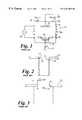
- FIG. 1is a schematic view of a reactor for processing semiconductors
- FIG. 2is a schematic illustration of a trench formed by a prior art method
- FIG. 3is an enlarged view of the mouth of the trench shown in FIG. 2;
- FIG. 4is a plot of etch rate of silicon against the percentage of CH 4 in H 2 ;
- FIG. 5is a plot of step coverage against the percentage of CH 4 in H 2 for different mean ion energies
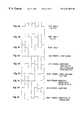
- FIGS. 6A-6Iare diagrams illustrating various possible synchronisations between gases and operating parameters of the FIG. 1 apparatus
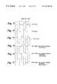
- FIGS. 7A-7Fare diagrams corresponding to FIGS. 6A-6I, but illustrating an alternative operating scenario
- FIG. 8is a plot of the etch rate of silicon against a partial pressure ratio
- FIG. 9 (A)is a schematic representation of parameter ramping for deep anisotropic profile control whilst 9 (B) illustrates ramping more generally;
- FIGS. 10 and 11are SEM's of a trench formed in accordance with the prior art, FIG. 11 being an enlargement of the mouth of FIG. 10;
- FIGS. 12 and 13are corresponding SEM's for a trench formed by the Applicants' process in which an abrupt transition in process parameters has occurred;
- FIG. 14corresponds to FIG. 12 except ramped parameters have been utilised
- FIG. 15is a plot of deposition rate against RF Platen Power at a variety of chamber pressures
- FIG. 16is a SEM of a prior art high aspect ratio trench
- FIG. 17is a corresponding SEM using the Applicants' process with abrupt transitions
- FIG. 18is a SEM of a high aspect ratio trench formed by the Applicants' process whilst using ramped transitions.
- FIGS. 19 (A) and 19 (B)are tables setting out the process conditions used for the trenches shown in FIGS. 14 and 18 respectively;
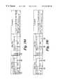
- FIG. 20is a diagram showing the synchronisation of Deposition and Etch gas during the initial cycles of the Applicants' process.
- FIG. 21is a diagram showing an alternative approach to FIG. 20 utilising a scavenger gas.
- FIG. 1illustrates schematically a prior art reactor chamber 10 , which is suitable for use both in reactive ion etching and chemical vapour deposition.
- a vacuum chamber 11incorporates a support electrode 12 for receiving a semiconductor wafer 13 and a further spaced electrode 14 .
- the wafer 13is pressed against the support 12 by a clamp 15 and is usually cooled, by backside cooling means (not shown).
- the chamber 11is surrounded by a coil 15 a and fed by a RF source 16 which is used to induce a plasma in the chamber 11 between the electrodes 12 and 14 .
- a microwave power supplymay be used to create the plasma.
- a plasma biaswhich can be either RF or DC and can be connected to the support electrode 12 so as to influence the passage of ions from the plasma down on to the wafer 13 .
- An example of such an adjustable bias meansis indicated at 17 .
- the chamberis provided with a gas inlet port 18 through which deposition or etched gases can be introduced and an exhaust port 19 for the removal of gaseous process products and any excess process gas. The operation of such a reactor in either the RIE or CVD modes is well understood in the art.
- FIG. 2The process described in that document uses sequential and discrete etch and deposition steps so that after the first etched step the sidewalls are undercut as shown at 20 and this undercut is then protected by a deposited passivation layer 21 .
- this arrangementproduces a rough sidewall and as the etched steps increase, or indeed the aspect ratio increases, there can be bowing or re-entrant notching in the profile.
- the prior art documentsdescribe the deposition of CF x passivation layers.
- the Applicantspropose a series of improvements to such processes to enable the formation of more smooth walled formations and particularly better quality deep and/or high aspect ratio formations. For convenience the description will therefore be divided into sections.
- these films or layersare also desirably deposited at high self biases eg. 20 eV upwards and preferably over 100 eV, there is an additional significant advantage when it comes to high aspect ratio formations, because the high self-bias ensures that the transport of the depositing material down to the base of the formation being etched is enhanced to prevent re-entrant sidewall etching.
- This transportation effectcan also be improved by progressively reducing the chamber pressure and/or increasing the gas flow rate, so as to reduce the residence time.
- the feature opening size(or critical dimension) can be in the ⁇ 0.5 ⁇ m range.
- hydrocarbon (H—C) films formed by this passivationhave significant advantages over the prior art fluorocarbon films.
- the H—C filmscan for example be readily removed after etching processing has been completed by dry ashing (oxygen plasma) treatment. This can be particularly important in the formation of MEMS (micro-electro-mechanical systems) where wet processing can result in sticking of resonant structures which are separated by high aspect trenches. In other applications, eg. optical or biomedical devices, it can be essential to remove completely the side wall layer.
- dry ashingoxygen plasma
- the H—C filmsmay be deposited from a wide range of H—C precursors (eg. CH 4 , C 2 H 4 , C 3 H 6 , C 4 H 8 , C 2 H 2 . etc. including high molecular weight aromatic H—C's). These may be mixed with noble gases and/or H 2 .
- An oxygen source gascan also be added (eg CO, CO 2 , O 2 etc.) can be used to control the phase balance of the film during deposition. The oxygen will tend to remove the graphitic phase (sp 2 ) of the carbon leaving the harder (sp 3 ) phase. Thus, the proportion of oxygen present will affect the characteristics of the film or layer, which is finally deposited.
- H 2can be mixed in with the H—C precursor.
- H 2will preferentially etch silicon and if the proportions are correctly selected, it is possible to achieve side wall passivation, whilst continuing the etching of the base of the hole during passivation phase.
- the preferred procedure for thisis to mix the selected H—C precursor (eg. CH 4 ) with H 2 and process a mask patterned silicon surface with the mixture in the apparatus, which is to be used for the proposed etch procedure.
- the silicon etch rateis plotted as a function of CH 4 concentration in H 2 and an example of such a plot is shown in FIG. 4 . It will be noted that the etch rate increases from an initial steady state with increasing percentage of CH 4 to a peak before decreasing to zero.
- the graphillustrates the following mechanisms taking place.
- the etchis essentially dominated by the action of H 2 to form SiHx reaction products.
- the CH 4 etching of the substratebecomes significant (by forming Si(CHx)y products) and the etch rate increases.
- Deposition of a hydrocarbon layeris taking place throughout although due to the etching there is no net deposition on this part of the graph.
- the depositionbegins to dominate the etching process until at around 38% for CH 4 , net deposition occurs.
- the layer or coating laid downis relatively hard because the reduced graphitic phase and the process can be operated in the rising portion of the etch rate graph, because the coating is much more resistant to etching, than the silicon substrate. It is thus possible to etch the silicon throughout the deposition phase. Selectivities exceeding 100:1 to mask or resist are readily achieved. It should particularly be noted that, whilst there is a significant removal of the graphitic phase due to ion bombardment of the mask, the high directionality of the ions means that the side wall coating is relatively untouched.
- the processcan also be operated at low mean ion energies either with a H—C precursor alone or with H 2 dilution. In that latter case it is preferred that the process is operated in the descending part of the etch graph. ie. for CH 4 at a percentage >18% but ⁇ 38% when net deposition occurs. Typically the range for CH 4 would be 18% to 30%.
- FIG. 5illustrates the step coverage (side wall deposition measured at 50% of the step height versus surface deposition) for H—C films using CH 4 and H 2 under a range of conditions including the two embodiments described above.
- FIG. 5shows that high ion energies increase the step coverage, but even with low bias conditions, there is sufficient passivation to protect against lateral etching. Further, in this latter case the higher deposition rate serves further to enhance the mask selectivity.
- the deposition rate at low ion energiesis a factor of two greater over the 100 ev case.
- FIGS. 6A-6Iillustrate how various parameters of the process may be synchronized.
- FIG. 6Dshows continuous and unchanging coil power
- FIG. 6Ecorrespondingly shows that the coil power is switched to enhance the etch or deposition step and the power during etch may be different to that selected for deposition depending on the process performance required.
- FIG. 6Eillustrates a higher coil power during deposition.
- FIGS. 6F to 6 Ishow similar variations in bias power.
- FIG. 6Fshows a high bias power during etch to allow ease of removal of the passivation film, whilst 6 G illustrates the use of an initial higher power pulse to enhance this removal process, whilst maintaining the mean ion energy lower, with resultant selectivity benefits.
- FIG. 6His a combination of FIGS. 6F and 6G for situations where situations where higher ion energies are required during etching (eg. with deep trenches).
- FIG. 6Isimply shows that bias may be off during deposition.
- the acceptable segregation period of the gasesis determined by the residual partial pressure of gas A (Ppa) which can be tolerated in the partial pressure of gas B(Ppb).
- Pparesidual partial pressure of gas A
- Ppbresidual partial pressure of gas B(Ppb)
- This minimum value of Ppa in Ppbis established from the characteristic process rate (etch or deposition) as a function of Ppa/(Ppa+Ppb).
- 4,985,114propose switching off or reducing deposition gas flow for a long period before the plasma is switched on. This can mean that the plasma power is on only for a small portion of the total cycle times leading to a significant reduction in etch rate.
- the Applicantspropose that the chamber should be pumped out between at least some of the gas changeovers, but care must be taken to maintain pressure and gas flow stabilization.
- high response speed mass flow controllersrise times less than 100 ms
- automatic pressure controllersangle change and stabilise in less than 300 ms
- rampingcan be used to allow mixing at the start of the process allowing sidewall notching to be reduced or eliminated as discussed below.
- CH 4 step time2-15 seconds; 4-6 seconds preferred
- H 2 step time2-15 seconds; 4-6 seconds preferred
- Coil rf power600W-1 kW; 800W preferred
- Bias rf powerHigh mean in energy case: 500W-300W-100W preferred
- SF 6 step time2-15 seconds; 4-6 seconds preferred
- Bias rf powerHigh mean ion energy case: 50W-300W; 150W preferred
- WO-A-94114187the Applicants believe that it will often be beneficial to overlap the etch and passivation or deposition steps so that the surface wall roughness indicated in FIG. 2 can be significantly reduced.
- the Applicantshave also established that surprisingly the rigid sequential square wave stepping which has previously been used is far from ideal. In many instances, it will be desirable to use smooth transitions between the stages, particularly where overlap occurs, when reduction of the etch rate is acceptable.
- the gas flow rates of the etch and deposition gasesto vary with time in a sinusoidal manner the two “wave forms” being out of phase, preferably by close to 90°.
- the sidewall roughnessis essentially a manifestation of the enhanced lateral etch component, it can be reduced by limiting this component of the etch.
- the desired effectcan be obtained in one of a number of ways: partially mixing the passivation and etch steps (overlapping); minimising the etch (and hence corresponding passivation) duration; reducing the etch product volatility by reducing the wafer temperature; adding passivation component to the etch gas e.g. SF 6 with added O, N, C, CF x , CH x , or replacing the etch gas with one of lower reactive species liberating gas such as SF 6 replaced by CF x etc.
- the Applicantshave also appreciated that changes in the levels of etching and deposition are desirable at different stages within the process.
- the systemcan be tuned in an appropriate manner to achieve good anisotropic etching with proper sidewall passivation.
- the ‘sidewall notching’ problemis particularly sensitive to the exposed silicon area (worse at low exposed areas ⁇ 30%) and is also correspondingly worse at high silicon mean etch rates.
- the Applicantsbelieve such notching to be caused by a relatively high concentration of etch species, during the initial etch/deposition cycles. Therefore the solutions adopted by the Applicants are to either enhance the passivation or quench etch species during the first cycles. The latter can be achieved either by process adjustment (ramping one of more of the parameters) or by placing a material within the reactor which will consume (by chemical reaction) the etch species, such as Si, Ti, W etc. reacting with the F etchant. Such chemical loading has the drawback of reducing the mean etch rate, as the quenching is only necessary for the first few etch steps. Thus, process adjustment solutions are considered superior.
- FIG. 3schematically and in the SEM's (scanning electron micrographs) shown in FIG. 10 and 11.
- SEM'sscanning electron micrographs
- the notched sidewallcan be modified. If abrupt steps are used to vary the process parameters, abrupt transitions are produced in the sidewall profiles.
- the SEMs in FIGS. 12 and 13illustrate this for different process parameters.
- the transition in the process parametersis clearly marked as an abrupt transition in the sidewall profile at the point of parameter change (after 8.5 ⁇ m etch depth). (Note that the sidewall notches have been eliminated.)
- FIG. 13illustrates yet another process parameter abrupt/step change.
- the sidewall passivationis high enough to result in a positive profile (and no notching) for the first 2 ⁇ m. When the reduced passivation conditions are applied, it is characterized by the transition in sidewall angle and reappearance of the notching.
- FIG. 20illustrates a synchronization between deposition and etch gases which have been used for the initial cycles to reduce side wall notching. Typical operating conditions are given in FIG. 19 A and its associated SEM in FIG. 14 .
- FIG. 21illustrates a synchronisation reference to using a scavenger gas with method (a) of side wall notch reduction technique. The dotted line indicates the alternative of the scavenger gas flow rate being decreasingly ramped.
- FIG. 9Ashows a synchronization for achieving a deep high aspect ratio anisotropic etch although the ramping technique shown can also be used for side wall notch reduction.
- the conditions of FIG. 19Bcan be used to achieve the results shown in FIG. 18 .
- biaschanges from low to high as the cycle changes from deposition to etch respectively, in synchronization to the pressure.
- the ramp up of biasrefers to both the deposition step and etch step in this case.
- FIG. 9Bgeneral parameter ramping is illustrated. These examples serve to illustrate cycle time and step time ramping respectively.
- the parameter rampmay be increasing or decreasing in magnitude, and the decrease may be to either zero or a non-zero value.
- etch gasesWhilst any suitable etch gases may be used, the Applicants have found that certain gases or mixture can be beneficial.
- the degree of sidewall roughnesscan also alternatively be reduced by limiting the cycle times. For example it has been discovered that it is desirable to limit the etch and deposition periods to less than 7.5 seconds and preferably less than 5 seconds.
Landscapes
- Engineering & Computer Science (AREA)
- Physics & Mathematics (AREA)
- Microelectronics & Electronic Packaging (AREA)
- General Physics & Mathematics (AREA)
- Manufacturing & Machinery (AREA)
- Computer Hardware Design (AREA)
- Condensed Matter Physics & Semiconductors (AREA)
- Power Engineering (AREA)
- Plasma & Fusion (AREA)
- Drying Of Semiconductors (AREA)
- ing And Chemical Polishing (AREA)
- Mechanical Treatment Of Semiconductor (AREA)
- Crystals, And After-Treatments Of Crystals (AREA)
Abstract
Description

Claims (23)

Applications Claiming Priority (2)
| Application Number | Priority Date | Filing Date | Title |
|---|---|---|---|
| GBGB9616225.0AGB9616225D0 (en) | 1996-08-01 | 1996-08-01 | Method of surface treatment of semiconductor substrates |
| GB9616225 | 1996-08-01 |
Publications (1)
| Publication Number | Publication Date |
|---|---|
| US6261962B1true US6261962B1 (en) | 2001-07-17 |
Family
ID=10797892
Family Applications (1)
| Application Number | Title | Priority Date | Filing Date |
|---|---|---|---|
| US08/904,954Expired - LifetimeUS6261962B1 (en) | 1996-08-01 | 1997-08-01 | Method of surface treatment of semiconductor substrates |
Country Status (6)
| Country | Link |
|---|---|
| US (1) | US6261962B1 (en) |
| EP (1) | EP0822584B1 (en) |
| JP (1) | JP4237281B2 (en) |
| AT (1) | ATE346379T1 (en) |
| DE (1) | DE69736969T2 (en) |
| GB (1) | GB9616225D0 (en) |
Cited By (54)
| Publication number | Priority date | Publication date | Assignee | Title |
|---|---|---|---|---|
| US6451673B1 (en)* | 2001-02-15 | 2002-09-17 | Advanced Micro Devices, Inc. | Carrier gas modification for preservation of mask layer during plasma etching |
| WO2004017368A2 (en) | 2002-08-16 | 2004-02-26 | Unaxis Usa, Inc. | Sidewall smoothing in high aspect ratio/deep etching using a discreet gas switching method |
| US20040072430A1 (en)* | 2002-10-11 | 2004-04-15 | Zhisong Huang | Method for forming a dual damascene structure |
| US20040072443A1 (en)* | 2002-10-11 | 2004-04-15 | Lam Research Corporation | Method for plasma etching performance enhancement |
| US20040124494A1 (en)* | 2002-06-28 | 2004-07-01 | Stmicroelectronics S.R.I. | Process for forming trenches with oblique profile and rounded top corners |
| US6812152B2 (en)* | 2001-08-09 | 2004-11-02 | Comlase Ab | Method to obtain contamination free laser mirrors and passivation of these |
| US20040224520A1 (en)* | 2003-04-09 | 2004-11-11 | Lam Research Corporation | Method for plasma stripping using periodic modulation of gas chemistry and hydrocarbon addition |
| US20050048785A1 (en)* | 2003-08-26 | 2005-03-03 | Lam Research Corporation | Reduction of feature critical dimensions |
| US20050090116A1 (en)* | 2003-10-24 | 2005-04-28 | Mirkarimi Laura W. | Method for etching smooth sidewalls in III-V based compounds for electro-optical devices |
| US20050136682A1 (en)* | 2003-04-09 | 2005-06-23 | Lam Research Corporation | Method for plasma etching using periodic modulation of gas chemistry |
| US20060011578A1 (en)* | 2004-07-16 | 2006-01-19 | Lam Research Corporation | Low-k dielectric etch |
| US20060113277A1 (en)* | 2004-12-01 | 2006-06-01 | Lexmark International, Inc. | Micro-fluid ejection head containing reentrant fluid feed slots |
| US20060134917A1 (en)* | 2004-12-16 | 2006-06-22 | Lam Research Corporation | Reduction of etch mask feature critical dimensions |
| US20060131271A1 (en)* | 2004-12-22 | 2006-06-22 | Adrian Kiermasz | Methods and apparatus for sequentially alternating among plasma processes in order to optimize a substrate |
| US20060194439A1 (en)* | 2005-03-08 | 2006-08-31 | Lam Research Corporation | Etch with striation control |
| US20060205220A1 (en)* | 2005-03-08 | 2006-09-14 | Lam Research Corporation | Stabilized photoresist structure for etching process |
| US20060205238A1 (en)* | 2002-08-02 | 2006-09-14 | Chinn Jeffrey D | Silicon-containing structure with deep etched features, and method of manufacture |
| US20060223322A1 (en)* | 2001-10-09 | 2006-10-05 | Liang-Yuh Chen | Method of forming a trench structure |
| US20060281324A1 (en)* | 2005-06-14 | 2006-12-14 | Alcatel | Method of controlling the pressure in a process chamber |
| CN1296270C (en)* | 2003-11-14 | 2007-01-24 | 索尼株式会社 | Etching method |
| US20070042607A1 (en)* | 2005-08-18 | 2007-02-22 | Lam Research Corporation | Etch features with reduced line edge roughness |
| US20070054092A1 (en)* | 2005-09-08 | 2007-03-08 | Tocalo Co., Ltd. | Spray-coated member having an excellent resistance to plasma erosion and method of producing the same |
| US7192531B1 (en) | 2003-06-24 | 2007-03-20 | Lam Research Corporation | In-situ plug fill |
| CN1331729C (en)* | 2003-10-29 | 2007-08-15 | 索尼株式会社 | Etching process |
| US20070190743A1 (en)* | 2005-12-28 | 2007-08-16 | Roberto Colombo | Process for digging a deep trench in a semiconductor body and semiconductor body so obtained |
| US20070193973A1 (en)* | 2006-02-17 | 2007-08-23 | Lam Research Corporation | Infinitely selective photoresist mask etch |
| US20070212888A1 (en)* | 2004-03-29 | 2007-09-13 | Sumitomo Precision Products Co., Ltd. | Silicon Substrate Etching Method |
| US20070218302A1 (en)* | 2006-03-20 | 2007-09-20 | Tokyo Electron Limited | Ceramic coating member for semiconductor processing apparatus |
| US7309646B1 (en) | 2006-10-10 | 2007-12-18 | Lam Research Corporation | De-fluoridation process |
| US20080239428A1 (en)* | 2007-04-02 | 2008-10-02 | Inphase Technologies, Inc. | Non-ft plane angular filters |
| US20090001890A1 (en)* | 2007-06-29 | 2009-01-01 | Varian Semiconductor Equipment Associates, Inc. | Apparatus for Plasma Processing a Substrate and a Method Thereof |
| US20090120358A1 (en)* | 2005-08-22 | 2009-05-14 | Tocalo Co., Ltd. | Spray coating member having excellent injury resistance and so on and method for producing the same |
| US20090130436A1 (en)* | 2005-08-22 | 2009-05-21 | Yoshio Harada | Spray coating member having excellent heat emmision property and so on and method for producing the same |
| US20090208667A1 (en)* | 2006-03-20 | 2009-08-20 | Tocalo Co. Ltd | Method for manufacturing ceramic covering member for semiconductor processing apparatus |
| US20100068395A1 (en)* | 2004-11-08 | 2010-03-18 | Tokyo Electron Limited | Method of producing ceramic spray-coated member, program for conducting the method, storage medium and ceramic spray-coated member |
| US20100197138A1 (en)* | 2009-01-31 | 2010-08-05 | Applied Materials, Inc. | Method and apparatus for etching |
| US7850864B2 (en) | 2006-03-20 | 2010-12-14 | Tokyo Electron Limited | Plasma treating apparatus and plasma treating method |
| US7977390B2 (en) | 2002-10-11 | 2011-07-12 | Lam Research Corporation | Method for plasma etching performance enhancement |
| US8133349B1 (en) | 2010-11-03 | 2012-03-13 | Lam Research Corporation | Rapid and uniform gas switching for a plasma etch process |
| US20130020026A1 (en)* | 2011-02-17 | 2013-01-24 | Lam Research Corporation | Wiggling control for pseudo-hardmask |
| US8440473B2 (en) | 2011-06-06 | 2013-05-14 | Lam Research Corporation | Use of spectrum to synchronize RF switching with gas switching during etch |
| US8609548B2 (en) | 2011-06-06 | 2013-12-17 | Lam Research Corporation | Method for providing high etch rate |
| CN103730411A (en)* | 2013-11-15 | 2014-04-16 | 中微半导体设备(上海)有限公司 | Through-silicon-via (TSV) etching method |
| CN103745945A (en)* | 2013-11-15 | 2014-04-23 | 中微半导体设备(上海)有限公司 | Deep silicon through hole etching apparatus and deep silicon through hole etching method |
| US8883648B1 (en)* | 2013-09-09 | 2014-11-11 | United Microelectronics Corp. | Manufacturing method of semiconductor structure |
| US20150011088A1 (en)* | 2012-02-29 | 2015-01-08 | Oxford Instruments Nanotechnology Tools Limited | Methods and apparatus for depositing and/or etching material on a substrate |
| US20150076111A1 (en)* | 2013-09-19 | 2015-03-19 | Globalfoundries Inc. | Feature etching using varying supply of power pulses |
| US9123509B2 (en) | 2007-06-29 | 2015-09-01 | Varian Semiconductor Equipment Associates, Inc. | Techniques for plasma processing a substrate |
| DE102004043357B4 (en)* | 2004-09-08 | 2015-10-22 | Robert Bosch Gmbh | Method for producing a micromechanical sensor element |
| CN105679700A (en)* | 2014-11-21 | 2016-06-15 | 北京北方微电子基地设备工艺研究中心有限责任公司 | Silicon deep hole etching method |
| US20180358209A1 (en)* | 2017-06-08 | 2018-12-13 | Samsung Electronics Co, Ltd. | Plasma processing apparatus |
| CN111584360A (en)* | 2019-02-18 | 2020-08-25 | 东京毅力科创株式会社 | Etching method |
| US10903109B2 (en) | 2017-12-29 | 2021-01-26 | Micron Technology, Inc. | Methods of forming high aspect ratio openings and methods of forming high aspect ratio features |
| US20210391181A1 (en)* | 2020-06-15 | 2021-12-16 | Tokyo Electron Limited | Forming a semiconductor device using a protective layer |
Families Citing this family (37)
| Publication number | Priority date | Publication date | Assignee | Title |
|---|---|---|---|---|
| US6849471B2 (en) | 2003-03-28 | 2005-02-01 | Reflectivity, Inc. | Barrier layers for microelectromechanical systems |
| US6969635B2 (en) | 2000-12-07 | 2005-11-29 | Reflectivity, Inc. | Methods for depositing, releasing and packaging micro-electromechanical devices on wafer substrates |
| GB9709659D0 (en) | 1997-05-13 | 1997-07-02 | Surface Tech Sys Ltd | Method and apparatus for etching a workpiece |
| US6355181B1 (en) | 1998-03-20 | 2002-03-12 | Surface Technology Systems Plc | Method and apparatus for manufacturing a micromechanical device |
| WO2000036631A1 (en) | 1998-12-11 | 2000-06-22 | Surface Technology Systems Limited | Plasma processing apparatus |
| DE60015270T2 (en)* | 1999-04-14 | 2006-02-09 | Surface Technology Systems Plc, Newport | METHOD AND DEVICE FOR STABILIZING A PLASMA |
| KR100750420B1 (en)* | 1999-08-17 | 2007-08-21 | 동경 엘렉트론 주식회사 | Plasma assisted process execution method and plasma assisted process execution reactor |
| US7041224B2 (en) | 1999-10-26 | 2006-05-09 | Reflectivity, Inc. | Method for vapor phase etching of silicon |
| US6949202B1 (en) | 1999-10-26 | 2005-09-27 | Reflectivity, Inc | Apparatus and method for flow of process gas in an ultra-clean environment |
| US6960305B2 (en) | 1999-10-26 | 2005-11-01 | Reflectivity, Inc | Methods for forming and releasing microelectromechanical structures |
| US6942811B2 (en) | 1999-10-26 | 2005-09-13 | Reflectivity, Inc | Method for achieving improved selectivity in an etching process |
| US6290864B1 (en) | 1999-10-26 | 2001-09-18 | Reflectivity, Inc. | Fluoride gas etching of silicon with improved selectivity |
| US7019376B2 (en) | 2000-08-11 | 2006-03-28 | Reflectivity, Inc | Micromirror array device with a small pitch size |
| US7189332B2 (en) | 2001-09-17 | 2007-03-13 | Texas Instruments Incorporated | Apparatus and method for detecting an endpoint in a vapor phase etch |
| US6965468B2 (en) | 2003-07-03 | 2005-11-15 | Reflectivity, Inc | Micromirror array having reduced gap between adjacent micromirrors of the micromirror array |
| US7027200B2 (en) | 2002-03-22 | 2006-04-11 | Reflectivity, Inc | Etching method used in fabrications of microstructures |
| EP1556325A4 (en) | 2002-09-20 | 2007-09-19 | Integrated Dna Tech Inc | Anthraquinone quencher dyes, their methods of preparation and use |
| DE10247913A1 (en)* | 2002-10-14 | 2004-04-22 | Robert Bosch Gmbh | Process for the anisotropic etching of structures in a substrate arranged in an etching chamber used in semiconductor manufacture comprises using an etching gas and a passivating gas which is fed to the chamber in defined periods |
| US20040097077A1 (en)* | 2002-11-15 | 2004-05-20 | Applied Materials, Inc. | Method and apparatus for etching a deep trench |
| US6913942B2 (en) | 2003-03-28 | 2005-07-05 | Reflectvity, Inc | Sacrificial layers for use in fabrications of microelectromechanical devices |
| US6980347B2 (en) | 2003-07-03 | 2005-12-27 | Reflectivity, Inc | Micromirror having reduced space between hinge and mirror plate of the micromirror |
| DE10333995B4 (en) | 2003-07-25 | 2018-10-25 | Robert Bosch Gmbh | Method for etching a semiconductor material |
| US7645704B2 (en) | 2003-09-17 | 2010-01-12 | Texas Instruments Incorporated | Methods and apparatus of etch process control in fabrications of microstructures |
| US7041226B2 (en)* | 2003-11-04 | 2006-05-09 | Lexmark International, Inc. | Methods for improving flow through fluidic channels |
| JP4578887B2 (en)* | 2004-08-11 | 2010-11-10 | 住友精密工業株式会社 | Etching method and etching apparatus |
| JP4512533B2 (en)* | 2005-07-27 | 2010-07-28 | 住友精密工業株式会社 | Etching method and etching apparatus |
| JP4996868B2 (en)* | 2006-03-20 | 2012-08-08 | 東京エレクトロン株式会社 | Plasma processing apparatus and plasma processing method |
| JP2008205436A (en)* | 2007-01-26 | 2008-09-04 | Toshiba Corp | Manufacturing method of fine structure |
| JP4769737B2 (en)* | 2007-01-30 | 2011-09-07 | 住友精密工業株式会社 | Etching method and etching apparatus |
| US7846846B2 (en)* | 2007-09-25 | 2010-12-07 | Applied Materials, Inc. | Method of preventing etch profile bending and bowing in high aspect ratio openings by treating a polymer formed on the opening sidewalls |
| JP5172417B2 (en)* | 2008-03-27 | 2013-03-27 | Sppテクノロジーズ株式会社 | Manufacturing method of silicon structure, manufacturing apparatus thereof, and manufacturing program thereof |
| JP5792613B2 (en)* | 2011-12-28 | 2015-10-14 | 株式会社日立ハイテクノロジーズ | Plasma etching method |
| DE102013100035B4 (en)* | 2012-05-24 | 2019-10-24 | Universität Kassel | Etching process for III-V semiconductor materials |
| JP6128972B2 (en)* | 2013-06-06 | 2017-05-17 | キヤノン株式会社 | Manufacturing method of substrate for liquid discharge head |
| JP2017079273A (en)* | 2015-10-21 | 2017-04-27 | パナソニックIpマネジメント株式会社 | Plasma processing method |
| JP7450455B2 (en)* | 2020-05-13 | 2024-03-15 | 東京エレクトロン株式会社 | Plasma processing equipment and plasma processing method |
| GB2629555A (en) | 2023-01-25 | 2024-11-06 | Memsstar Ltd | Method of manufacturing a microstructure |
Citations (32)
| Publication number | Priority date | Publication date | Assignee | Title |
|---|---|---|---|---|
| US4533430A (en) | 1984-01-04 | 1985-08-06 | Advanced Micro Devices, Inc. | Process for forming slots having near vertical sidewalls at their upper extremities |
| EP0160220A1 (en) | 1984-04-02 | 1985-11-06 | International Business Machines Corporation | Plasma etching apparatus |
| US4599135A (en) | 1983-09-30 | 1986-07-08 | Hitachi, Ltd. | Thin film deposition |
| US4635090A (en) | 1980-09-17 | 1987-01-06 | Hitachi, Ltd. | Tapered groove IC isolation |
| JPS62136066A (en) | 1985-12-09 | 1987-06-19 | Mitsubishi Electric Corp | Manufacturing method of semiconductor device |
| US4707218A (en) | 1986-10-28 | 1987-11-17 | International Business Machines Corporation | Lithographic image size reduction |
| EP0246514A2 (en) | 1986-05-16 | 1987-11-25 | Air Products And Chemicals, Inc. | Deep trench etching of single crystal silicon |
| US4784720A (en) | 1985-05-03 | 1988-11-15 | Texas Instruments Incorporated | Trench etch process for a single-wafer RIE dry etch reactor |
| US4795529A (en) | 1986-10-17 | 1989-01-03 | Hitachi, Ltd. | Plasma treating method and apparatus therefor |
| WO1989001701A1 (en) | 1987-08-07 | 1989-02-23 | Cobrain N.V. | A method and apparatus for dry processing or etching a substrate |
| US4832788A (en) | 1985-09-27 | 1989-05-23 | Unisys Corporation | Method of fabricating a tapered via hole in polyimide |
| US4855017A (en)* | 1985-05-03 | 1989-08-08 | Texas Instruments Incorporated | Trench etch process for a single-wafer RIE dry etch reactor |
| EP0350997A2 (en) | 1988-07-11 | 1990-01-17 | Koninklijke Philips Electronics N.V. | Reactive ion etching of a silicon-bearing material with hydrobromic acid |
| EP0363982A2 (en) | 1988-10-14 | 1990-04-18 | Hitachi, Ltd. | Dry etching method |
| EP0383570A2 (en) | 1989-02-15 | 1990-08-22 | Hitachi, Ltd. | Plasma etching method and apparatus |
| JPH03126222A (en) | 1989-10-12 | 1991-05-29 | Canon Inc | Deposited film formation method |
| JPH03129820A (en) | 1989-10-16 | 1991-06-03 | Seiko Epson Corp | Apparatus for manufacturing semiconductor and manufacture of semiconductor device |
| US5068202A (en) | 1988-12-15 | 1991-11-26 | Sgs-Thomson Microelectronics S.R.L. | Process for excavating trenches with a rounded bottom in a silicon substrate for making trench isolation structures |
| US5074955A (en)* | 1987-05-21 | 1991-12-24 | L'etat Francais Represente Par Le Ministre Des Postes, Des Telecommunications Et De L'espace (C.N.E.T.) | Process for the anisotropic etching of a iii-v material and application to the surface treatment for epitaxial growth |
| US5079178A (en) | 1988-12-19 | 1992-01-07 | L'etat Francais Represente Par Le Ministre Des Postes, Des Telecommunications Et De L'espace (Centre National D'etudes Des Telecommunications) | Process for etching a metal oxide coating and simultaneous deposition of a polymer film, application of this process to the production of a thin film transistor |
| EP0482519A1 (en) | 1990-10-19 | 1992-04-29 | Tokyo Electron Limited | Method of etching oxide materials |
| EP0536968A2 (en) | 1991-10-08 | 1993-04-14 | Nec Corporation | Process for forming contact holes in the fabrication of semi-conducteur devices |
| EP0562464A1 (en) | 1992-03-27 | 1993-09-29 | Hitachi, Ltd. | Vacuum processing apparatus |
| JPH0612767A (en) | 1992-06-25 | 1994-01-21 | Victor Co Of Japan Ltd | Device for automatic reproducing |
| WO1994014187A1 (en) | 1992-12-05 | 1994-06-23 | Robert Bosch Gmbh | Method for anisotropically etching silicon |
| US5368685A (en) | 1992-03-24 | 1994-11-29 | Hitachi, Ltd. | Dry etching apparatus and method |
| US5474650A (en) | 1991-04-04 | 1995-12-12 | Hitachi, Ltd. | Method and apparatus for dry etching |
| US5478437A (en) | 1994-08-01 | 1995-12-26 | Motorola, Inc. | Selective processing using a hydrocarbon and hydrogen |
| US5605600A (en) | 1995-03-13 | 1997-02-25 | International Business Machines Corporation | Etch profile shaping through wafer temperature control |
| US6051503A (en)* | 1996-08-01 | 2000-04-18 | Surface Technology Systems Limited | Method of surface treatment of semiconductor substrates |
| JP3126222B2 (en) | 1992-05-18 | 2001-01-22 | 株式会社たつみや漆器 | Food containers made of synthetic resin |
| JP3129820B2 (en) | 1992-03-04 | 2001-01-31 | シスメックス株式会社 | Particle detector |
Family Cites Families (2)
| Publication number | Priority date | Publication date | Assignee | Title |
|---|---|---|---|---|
| JPS58147032A (en)* | 1982-02-24 | 1983-09-01 | Toshiba Corp | Manufacturing method of semiconductor device |
| JP2772643B2 (en)* | 1988-08-26 | 1998-07-02 | 株式会社半導体エネルギー研究所 | Coating method |
- 1996
- 1996-08-01GBGBGB9616225.0Apatent/GB9616225D0/enactivePending
- 1997
- 1997-07-28DEDE69736969Tpatent/DE69736969T2/ennot_activeExpired - Lifetime
- 1997-07-28EPEP97305641Apatent/EP0822584B1/ennot_activeExpired - Lifetime
- 1997-07-28ATAT97305641Tpatent/ATE346379T1/ennot_activeIP Right Cessation
- 1997-07-31JPJP20667397Apatent/JP4237281B2/ennot_activeExpired - Lifetime
- 1997-08-01USUS08/904,954patent/US6261962B1/ennot_activeExpired - Lifetime
Patent Citations (34)
| Publication number | Priority date | Publication date | Assignee | Title |
|---|---|---|---|---|
| US4635090A (en) | 1980-09-17 | 1987-01-06 | Hitachi, Ltd. | Tapered groove IC isolation |
| US4599135A (en) | 1983-09-30 | 1986-07-08 | Hitachi, Ltd. | Thin film deposition |
| US4533430A (en) | 1984-01-04 | 1985-08-06 | Advanced Micro Devices, Inc. | Process for forming slots having near vertical sidewalls at their upper extremities |
| EP0160220A1 (en) | 1984-04-02 | 1985-11-06 | International Business Machines Corporation | Plasma etching apparatus |
| US4784720A (en) | 1985-05-03 | 1988-11-15 | Texas Instruments Incorporated | Trench etch process for a single-wafer RIE dry etch reactor |
| US4855017A (en)* | 1985-05-03 | 1989-08-08 | Texas Instruments Incorporated | Trench etch process for a single-wafer RIE dry etch reactor |
| US4832788A (en) | 1985-09-27 | 1989-05-23 | Unisys Corporation | Method of fabricating a tapered via hole in polyimide |
| JPS62136066A (en) | 1985-12-09 | 1987-06-19 | Mitsubishi Electric Corp | Manufacturing method of semiconductor device |
| EP0246514A2 (en) | 1986-05-16 | 1987-11-25 | Air Products And Chemicals, Inc. | Deep trench etching of single crystal silicon |
| US4795529A (en) | 1986-10-17 | 1989-01-03 | Hitachi, Ltd. | Plasma treating method and apparatus therefor |
| US4707218A (en) | 1986-10-28 | 1987-11-17 | International Business Machines Corporation | Lithographic image size reduction |
| US5074955A (en)* | 1987-05-21 | 1991-12-24 | L'etat Francais Represente Par Le Ministre Des Postes, Des Telecommunications Et De L'espace (C.N.E.T.) | Process for the anisotropic etching of a iii-v material and application to the surface treatment for epitaxial growth |
| WO1989001701A1 (en) | 1987-08-07 | 1989-02-23 | Cobrain N.V. | A method and apparatus for dry processing or etching a substrate |
| EP0350997A2 (en) | 1988-07-11 | 1990-01-17 | Koninklijke Philips Electronics N.V. | Reactive ion etching of a silicon-bearing material with hydrobromic acid |
| EP0363982A2 (en) | 1988-10-14 | 1990-04-18 | Hitachi, Ltd. | Dry etching method |
| US4985114A (en) | 1988-10-14 | 1991-01-15 | Hitachi, Ltd. | Dry etching by alternately etching and depositing |
| US5068202A (en) | 1988-12-15 | 1991-11-26 | Sgs-Thomson Microelectronics S.R.L. | Process for excavating trenches with a rounded bottom in a silicon substrate for making trench isolation structures |
| US5079178A (en) | 1988-12-19 | 1992-01-07 | L'etat Francais Represente Par Le Ministre Des Postes, Des Telecommunications Et De L'espace (Centre National D'etudes Des Telecommunications) | Process for etching a metal oxide coating and simultaneous deposition of a polymer film, application of this process to the production of a thin film transistor |
| EP0383570A2 (en) | 1989-02-15 | 1990-08-22 | Hitachi, Ltd. | Plasma etching method and apparatus |
| JPH03126222A (en) | 1989-10-12 | 1991-05-29 | Canon Inc | Deposited film formation method |
| JPH03129820A (en) | 1989-10-16 | 1991-06-03 | Seiko Epson Corp | Apparatus for manufacturing semiconductor and manufacture of semiconductor device |
| EP0482519A1 (en) | 1990-10-19 | 1992-04-29 | Tokyo Electron Limited | Method of etching oxide materials |
| US5474650A (en) | 1991-04-04 | 1995-12-12 | Hitachi, Ltd. | Method and apparatus for dry etching |
| EP0536968A2 (en) | 1991-10-08 | 1993-04-14 | Nec Corporation | Process for forming contact holes in the fabrication of semi-conducteur devices |
| JP3129820B2 (en) | 1992-03-04 | 2001-01-31 | シスメックス株式会社 | Particle detector |
| US5368685A (en) | 1992-03-24 | 1994-11-29 | Hitachi, Ltd. | Dry etching apparatus and method |
| EP0562464A1 (en) | 1992-03-27 | 1993-09-29 | Hitachi, Ltd. | Vacuum processing apparatus |
| JP3126222B2 (en) | 1992-05-18 | 2001-01-22 | 株式会社たつみや漆器 | Food containers made of synthetic resin |
| JPH0612767A (en) | 1992-06-25 | 1994-01-21 | Victor Co Of Japan Ltd | Device for automatic reproducing |
| WO1994014187A1 (en) | 1992-12-05 | 1994-06-23 | Robert Bosch Gmbh | Method for anisotropically etching silicon |
| US5501893A (en) | 1992-12-05 | 1996-03-26 | Robert Bosch Gmbh | Method of anisotropically etching silicon |
| US5478437A (en) | 1994-08-01 | 1995-12-26 | Motorola, Inc. | Selective processing using a hydrocarbon and hydrogen |
| US5605600A (en) | 1995-03-13 | 1997-02-25 | International Business Machines Corporation | Etch profile shaping through wafer temperature control |
| US6051503A (en)* | 1996-08-01 | 2000-04-18 | Surface Technology Systems Limited | Method of surface treatment of semiconductor substrates |
Non-Patent Citations (8)
| Title |
|---|
| D.W. Hess, "Plasma Etch Chemistry of Aluminum and Aluminum Alloy Films", Plasma Chemistry and Plasma Processing, vol. 2, No. 2, 1982, pp. 141-155. |
| K. Tsujimoto et al., "A New Side Wall Protection Technique in Microwave Plasma Etching Using a Chopping Method", 1986, Extended Abstracts of the 18th Conference on Solid State Devices and Materials, Tokyo, pp. 229-232.* |
| L.M. Ephrath, "Selective Etching of Silicon Dioxide Using Reactive Ion Etching with CF4-H2", J. Electrochem, Soc.: Solid-State Science and Technology, Aug. 1979, pp. 1419-1421. |
| Law et al., "Alkane based plasma etching of GaAs", 1991, Journal of Vacuum Science & Technology B, pp. 1449-1455.* |
| M. Law et al. 8257b Journal of Vacuum Science & Technology B 9 (1991) May/Jun., No. 3, New York, US Alkane based plasma etching of GaAs. |
| P. Bruice, Organic Chemistry, 1995, Prentice Hall, p. G-9.* |
| Patent Abstracts of Japan, Publication No.: 02061069; Publication Date: Mar. 1, 1990; Inventor: Kawano Atsushi: "Formation of Coating Film". |
| Patent Abstracts of Japan, Publication No.: 58147032; Publication Date: Sep. 1, 1983; Inventor: Nakayama Ryozo: "Preparation of Semiconductor Device". |
Cited By (106)
| Publication number | Priority date | Publication date | Assignee | Title |
|---|---|---|---|---|
| US6451673B1 (en)* | 2001-02-15 | 2002-09-17 | Advanced Micro Devices, Inc. | Carrier gas modification for preservation of mask layer during plasma etching |
| US6812152B2 (en)* | 2001-08-09 | 2004-11-02 | Comlase Ab | Method to obtain contamination free laser mirrors and passivation of these |
| US20060223322A1 (en)* | 2001-10-09 | 2006-10-05 | Liang-Yuh Chen | Method of forming a trench structure |
| US7772121B2 (en)* | 2001-10-09 | 2010-08-10 | Applied Materials, Inc. | Method of forming a trench structure |
| US20040124494A1 (en)* | 2002-06-28 | 2004-07-01 | Stmicroelectronics S.R.I. | Process for forming trenches with oblique profile and rounded top corners |
| US7618548B2 (en)* | 2002-08-02 | 2009-11-17 | Applied Materials, Inc. | Silicon-containing structure with deep etched features, and method of manufacture |
| US20060205238A1 (en)* | 2002-08-02 | 2006-09-14 | Chinn Jeffrey D | Silicon-containing structure with deep etched features, and method of manufacture |
| CN100409414C (en)* | 2002-08-16 | 2008-08-06 | 优利讯美国有限公司 | Sidewall smoothing in high aspect ratio/deep etching using a discrete gas switching method |
| WO2004017368A3 (en)* | 2002-08-16 | 2004-12-29 | Unaxis Usa Inc | Sidewall smoothing in high aspect ratio/deep etching using a discreet gas switching method |
| EP1543540A4 (en)* | 2002-08-16 | 2009-08-26 | Unaxis Usa Inc | Sidewall smoothing in high aspect ratio/deep etching using a discreet gas switching method |
| US20040092118A1 (en)* | 2002-08-16 | 2004-05-13 | David Johnson | Sidewall smoothing in high aspect ratio/deep etching using a discrete gas switching method |
| US6924235B2 (en)* | 2002-08-16 | 2005-08-02 | Unaxis Usa Inc. | Sidewall smoothing in high aspect ratio/deep etching using a discrete gas switching method |
| WO2004017368A2 (en) | 2002-08-16 | 2004-02-26 | Unaxis Usa, Inc. | Sidewall smoothing in high aspect ratio/deep etching using a discreet gas switching method |
| US6833325B2 (en) | 2002-10-11 | 2004-12-21 | Lam Research Corporation | Method for plasma etching performance enhancement |
| US20050037624A1 (en)* | 2002-10-11 | 2005-02-17 | Lam Research Corporation | Method for plasma etching performance enhancement |
| US20040072443A1 (en)* | 2002-10-11 | 2004-04-15 | Lam Research Corporation | Method for plasma etching performance enhancement |
| US20040072430A1 (en)* | 2002-10-11 | 2004-04-15 | Zhisong Huang | Method for forming a dual damascene structure |
| US7977390B2 (en) | 2002-10-11 | 2011-07-12 | Lam Research Corporation | Method for plasma etching performance enhancement |
| US7169695B2 (en) | 2002-10-11 | 2007-01-30 | Lam Research Corporation | Method for forming a dual damascene structure |
| US7294580B2 (en) | 2003-04-09 | 2007-11-13 | Lam Research Corporation | Method for plasma stripping using periodic modulation of gas chemistry and hydrocarbon addition |
| US20040224520A1 (en)* | 2003-04-09 | 2004-11-11 | Lam Research Corporation | Method for plasma stripping using periodic modulation of gas chemistry and hydrocarbon addition |
| US20050136682A1 (en)* | 2003-04-09 | 2005-06-23 | Lam Research Corporation | Method for plasma etching using periodic modulation of gas chemistry |
| US6916746B1 (en) | 2003-04-09 | 2005-07-12 | Lam Research Corporation | Method for plasma etching using periodic modulation of gas chemistry |
| US7192531B1 (en) | 2003-06-24 | 2007-03-20 | Lam Research Corporation | In-situ plug fill |
| US7541291B2 (en) | 2003-08-26 | 2009-06-02 | Lam Research Corporation | Reduction of feature critical dimensions |
| US20050048785A1 (en)* | 2003-08-26 | 2005-03-03 | Lam Research Corporation | Reduction of feature critical dimensions |
| US20070293050A1 (en)* | 2003-08-26 | 2007-12-20 | Lam Research Corporation | Reduction of feature critical dimensions |
| US7250371B2 (en) | 2003-08-26 | 2007-07-31 | Lam Research Corporation | Reduction of feature critical dimensions |
| CN1609712B (en)* | 2003-10-24 | 2010-11-03 | 安华高科技光纤Ip(新加坡)私人有限公司 | Method for etching smooth sidewalls in III-V based compounds for electro-optical devices |
| US7196017B2 (en)* | 2003-10-24 | 2007-03-27 | Avago Technologies Fiber Ip (Singapore) Pte. Ltd. | Method for etching smooth sidewalls in III-V based compounds for electro-optical devices |
| US20050090116A1 (en)* | 2003-10-24 | 2005-04-28 | Mirkarimi Laura W. | Method for etching smooth sidewalls in III-V based compounds for electro-optical devices |
| CN1331729C (en)* | 2003-10-29 | 2007-08-15 | 索尼株式会社 | Etching process |
| CN1296270C (en)* | 2003-11-14 | 2007-01-24 | 索尼株式会社 | Etching method |
| US20070212888A1 (en)* | 2004-03-29 | 2007-09-13 | Sumitomo Precision Products Co., Ltd. | Silicon Substrate Etching Method |
| US20060011578A1 (en)* | 2004-07-16 | 2006-01-19 | Lam Research Corporation | Low-k dielectric etch |
| DE102004043357B4 (en)* | 2004-09-08 | 2015-10-22 | Robert Bosch Gmbh | Method for producing a micromechanical sensor element |
| US20100068395A1 (en)* | 2004-11-08 | 2010-03-18 | Tokyo Electron Limited | Method of producing ceramic spray-coated member, program for conducting the method, storage medium and ceramic spray-coated member |
| US7202178B2 (en)* | 2004-12-01 | 2007-04-10 | Lexmark International, Inc. | Micro-fluid ejection head containing reentrant fluid feed slots |
| US20060113277A1 (en)* | 2004-12-01 | 2006-06-01 | Lexmark International, Inc. | Micro-fluid ejection head containing reentrant fluid feed slots |
| US20060134917A1 (en)* | 2004-12-16 | 2006-06-22 | Lam Research Corporation | Reduction of etch mask feature critical dimensions |
| US20060131271A1 (en)* | 2004-12-22 | 2006-06-22 | Adrian Kiermasz | Methods and apparatus for sequentially alternating among plasma processes in order to optimize a substrate |
| US7459100B2 (en) | 2004-12-22 | 2008-12-02 | Lam Research Corporation | Methods and apparatus for sequentially alternating among plasma processes in order to optimize a substrate |
| US20090121324A1 (en)* | 2005-03-08 | 2009-05-14 | Lam Research Corporation | Etch with striation control |
| US7491647B2 (en) | 2005-03-08 | 2009-02-17 | Lam Research Corporation | Etch with striation control |
| US20060194439A1 (en)* | 2005-03-08 | 2006-08-31 | Lam Research Corporation | Etch with striation control |
| US20060205220A1 (en)* | 2005-03-08 | 2006-09-14 | Lam Research Corporation | Stabilized photoresist structure for etching process |
| US7241683B2 (en) | 2005-03-08 | 2007-07-10 | Lam Research Corporation | Stabilized photoresist structure for etching process |
| US20060281324A1 (en)* | 2005-06-14 | 2006-12-14 | Alcatel | Method of controlling the pressure in a process chamber |
| US7399710B2 (en)* | 2005-06-14 | 2008-07-15 | Alcatel | Method of controlling the pressure in a process chamber |
| US20070284690A1 (en)* | 2005-08-18 | 2007-12-13 | Lam Research Corporation | Etch features with reduced line edge roughness |
| US7273815B2 (en) | 2005-08-18 | 2007-09-25 | Lam Research Corporation | Etch features with reduced line edge roughness |
| US20070042607A1 (en)* | 2005-08-18 | 2007-02-22 | Lam Research Corporation | Etch features with reduced line edge roughness |
| US20090120358A1 (en)* | 2005-08-22 | 2009-05-14 | Tocalo Co., Ltd. | Spray coating member having excellent injury resistance and so on and method for producing the same |
| US20090130436A1 (en)* | 2005-08-22 | 2009-05-21 | Yoshio Harada | Spray coating member having excellent heat emmision property and so on and method for producing the same |
| US8231986B2 (en) | 2005-08-22 | 2012-07-31 | Tocalo Co., Ltd. | Spray coating member having excellent injury resistance and so on and method for producing the same |
| US20100203288A1 (en)* | 2005-09-08 | 2010-08-12 | Tocalo Co., Ltd. | Spray-coated member having an excellent resistance to plasma erosion and method of producing the same |
| US20070054092A1 (en)* | 2005-09-08 | 2007-03-08 | Tocalo Co., Ltd. | Spray-coated member having an excellent resistance to plasma erosion and method of producing the same |
| US8053058B2 (en) | 2005-09-08 | 2011-11-08 | Tocalo Co., Ltd. | Spray-coated member having an excellent resistance to plasma erosion and method of producing the same |
| US7767268B2 (en) | 2005-09-08 | 2010-08-03 | Tocalo Co., Ltd. | Spray-coated member having an excellent resistance to plasma erosion and method of producing the same |
| US7544620B2 (en)* | 2005-12-28 | 2009-06-09 | Roberto Colombo | Process for digging a deep trench in a semiconductor body and semiconductor body so obtained |
| US20070190743A1 (en)* | 2005-12-28 | 2007-08-16 | Roberto Colombo | Process for digging a deep trench in a semiconductor body and semiconductor body so obtained |
| US7910489B2 (en) | 2006-02-17 | 2011-03-22 | Lam Research Corporation | Infinitely selective photoresist mask etch |
| US20070193973A1 (en)* | 2006-02-17 | 2007-08-23 | Lam Research Corporation | Infinitely selective photoresist mask etch |
| US20110030896A1 (en)* | 2006-03-20 | 2011-02-10 | Tokyo Electron Limited | Plasma treating apparatus and plasma treating method |
| US20070218302A1 (en)* | 2006-03-20 | 2007-09-20 | Tokyo Electron Limited | Ceramic coating member for semiconductor processing apparatus |
| US7850864B2 (en) | 2006-03-20 | 2010-12-14 | Tokyo Electron Limited | Plasma treating apparatus and plasma treating method |
| US7648782B2 (en) | 2006-03-20 | 2010-01-19 | Tokyo Electron Limited | Ceramic coating member for semiconductor processing apparatus |
| US20090208667A1 (en)* | 2006-03-20 | 2009-08-20 | Tocalo Co. Ltd | Method for manufacturing ceramic covering member for semiconductor processing apparatus |
| US7309646B1 (en) | 2006-10-10 | 2007-12-18 | Lam Research Corporation | De-fluoridation process |
| US20080083502A1 (en)* | 2006-10-10 | 2008-04-10 | Lam Research Corporation | De-fluoridation process |
| US8172948B2 (en) | 2006-10-10 | 2012-05-08 | Lam Research Corporation | De-fluoridation process |
| US20080239428A1 (en)* | 2007-04-02 | 2008-10-02 | Inphase Technologies, Inc. | Non-ft plane angular filters |
| US20090001890A1 (en)* | 2007-06-29 | 2009-01-01 | Varian Semiconductor Equipment Associates, Inc. | Apparatus for Plasma Processing a Substrate and a Method Thereof |
| US8926850B2 (en)* | 2007-06-29 | 2015-01-06 | Varian Semiconductor Equipment Associates, Inc. | Plasma processing with enhanced charge neutralization and process control |
| US9123509B2 (en) | 2007-06-29 | 2015-09-01 | Varian Semiconductor Equipment Associates, Inc. | Techniques for plasma processing a substrate |
| US20130092529A1 (en)* | 2007-06-29 | 2013-04-18 | Varian Semiconductor Equipment Associates, Inc. | Plasma processing with enhanced charge neutralization and process control |
| CN102768933A (en)* | 2009-01-31 | 2012-11-07 | 应用材料公司 | method for etching |
| US20120208300A1 (en)* | 2009-01-31 | 2012-08-16 | Applied Materials, Inc. | Etch processing chamber |
| CN102301458A (en)* | 2009-01-31 | 2011-12-28 | 应用材料公司 | Method and apparatus for etching |
| US20100197138A1 (en)* | 2009-01-31 | 2010-08-05 | Applied Materials, Inc. | Method and apparatus for etching |
| US8937017B2 (en) | 2009-01-31 | 2015-01-20 | Applied Materials, Inc. | Method and apparatus for etching |
| US8133349B1 (en) | 2010-11-03 | 2012-03-13 | Lam Research Corporation | Rapid and uniform gas switching for a plasma etch process |
| US9011631B2 (en) | 2010-11-03 | 2015-04-21 | Lam Research Corporation | Rapid and uniform gas switching for a plasma etch process |
| US8470126B2 (en)* | 2011-02-17 | 2013-06-25 | Lam Research Corporation | Wiggling control for pseudo-hardmask |
| US20130020026A1 (en)* | 2011-02-17 | 2013-01-24 | Lam Research Corporation | Wiggling control for pseudo-hardmask |
| US8609548B2 (en) | 2011-06-06 | 2013-12-17 | Lam Research Corporation | Method for providing high etch rate |
| US8440473B2 (en) | 2011-06-06 | 2013-05-14 | Lam Research Corporation | Use of spectrum to synchronize RF switching with gas switching during etch |
| US9412566B2 (en)* | 2012-02-29 | 2016-08-09 | Oxford Instruments Nanotechnology Tools Limited | Methods and apparatus for depositing and/or etching material on a substrate |
| TWI608533B (en)* | 2012-02-29 | 2017-12-11 | 牛津儀器奈米科技工具有限公司 | Methods and apparatus for depositing and/or etching material on a substrate |
| US20150011088A1 (en)* | 2012-02-29 | 2015-01-08 | Oxford Instruments Nanotechnology Tools Limited | Methods and apparatus for depositing and/or etching material on a substrate |
| US8883648B1 (en)* | 2013-09-09 | 2014-11-11 | United Microelectronics Corp. | Manufacturing method of semiconductor structure |
| US20150076111A1 (en)* | 2013-09-19 | 2015-03-19 | Globalfoundries Inc. | Feature etching using varying supply of power pulses |
| US9401263B2 (en)* | 2013-09-19 | 2016-07-26 | Globalfoundries Inc. | Feature etching using varying supply of power pulses |
| CN103730411A (en)* | 2013-11-15 | 2014-04-16 | 中微半导体设备(上海)有限公司 | Through-silicon-via (TSV) etching method |
| CN103745945A (en)* | 2013-11-15 | 2014-04-23 | 中微半导体设备(上海)有限公司 | Deep silicon through hole etching apparatus and deep silicon through hole etching method |
| CN103730411B (en)* | 2013-11-15 | 2017-01-25 | 中微半导体设备(上海)有限公司 | Through-silicon-via (TSV) etching method |
| CN103745945B (en)* | 2013-11-15 | 2017-02-15 | 中微半导体设备(上海)有限公司 | Deep silicon through hole etching apparatus and deep silicon through hole etching method |
| CN105679700A (en)* | 2014-11-21 | 2016-06-15 | 北京北方微电子基地设备工艺研究中心有限责任公司 | Silicon deep hole etching method |
| US20180358209A1 (en)* | 2017-06-08 | 2018-12-13 | Samsung Electronics Co, Ltd. | Plasma processing apparatus |
| US10903109B2 (en) | 2017-12-29 | 2021-01-26 | Micron Technology, Inc. | Methods of forming high aspect ratio openings and methods of forming high aspect ratio features |
| US11417565B2 (en) | 2017-12-29 | 2022-08-16 | Micron Technology, Inc. | Methods of forming high aspect ratio openings and methods of forming high aspect ratio features |
| US11854869B2 (en) | 2017-12-29 | 2023-12-26 | Micron Technology, Inc. | Methods of forming high aspect ratio features |
| CN111584360A (en)* | 2019-02-18 | 2020-08-25 | 东京毅力科创株式会社 | Etching method |
| CN111584360B (en)* | 2019-02-18 | 2024-04-19 | 东京毅力科创株式会社 | Etching method |
| US20210391181A1 (en)* | 2020-06-15 | 2021-12-16 | Tokyo Electron Limited | Forming a semiconductor device using a protective layer |
| US12266534B2 (en)* | 2020-06-15 | 2025-04-01 | Tokyo Electron Limited | Forming a semiconductor device using a protective layer |
Also Published As
| Publication number | Publication date |
|---|---|
| ATE346379T1 (en) | 2006-12-15 |
| EP0822584A2 (en) | 1998-02-04 |
| EP0822584B1 (en) | 2006-11-22 |
| DE69736969T2 (en) | 2007-10-18 |
| GB9616225D0 (en) | 1996-09-11 |
| JP4237281B2 (en) | 2009-03-11 |
| JPH10144654A (en) | 1998-05-29 |
| EP0822584A3 (en) | 1998-05-13 |
| DE69736969D1 (en) | 2007-01-04 |
Similar Documents
| Publication | Publication Date | Title |
|---|---|---|
| US6261962B1 (en) | Method of surface treatment of semiconductor substrates | |
| US6051503A (en) | Method of surface treatment of semiconductor substrates | |
| US6569774B1 (en) | Method to eliminate striations and surface roughness caused by dry etch | |
| US20210104399A1 (en) | Methods for forming a topographically selective silicon oxide film by a cyclical plasma-enhanced deposition process | |
| US11018014B2 (en) | Dry etching method | |
| US6489248B2 (en) | Method and apparatus for etch passivating and etching a substrate | |
| JP4657458B2 (en) | Techniques for etching low-capacity dielectric layers | |
| JP4601113B2 (en) | Anisotropic etching method for substrates | |
| US5354417A (en) | Etching MoSi2 using SF6, HBr and O2 | |
| US5300460A (en) | UHF/VHF plasma for use in forming integrated circuit structures on semiconductor wafers | |
| US6784108B1 (en) | Gas pulsing for etch profile control | |
| US20210050222A1 (en) | Plasma etching method | |
| US6890863B1 (en) | Etchant and method of use | |
| JP2004512668A (en) | Magnetically enhanced plasma etching method using fluorocarbon etching gas | |
| KR100255405B1 (en) | Dry etching method | |
| US7736914B2 (en) | Plasma control using dual cathode frequency mixing and controlling the level of polymer formation | |
| JP4008352B2 (en) | Insulating film etching method | |
| JP2010021442A (en) | Plasma processing method and apparatus | |
| WO2009110567A1 (en) | Plasma processing method | |
| US6486070B1 (en) | Ultra-high oxide to photoresist selective etch of high-aspect-ratio openings in a low-pressure, high-density plasma | |
| US6828251B2 (en) | Method for improved plasma etching control | |
| US6653237B2 (en) | High resist-selectivity etch for silicon trench etch applications | |
| WO1997024750A1 (en) | Method for etching silicon dioxide using unsaturated fluorocarbons | |
| JPH0859215A (en) | Nitride etching process | |
| JPH0121230B2 (en) |
Legal Events
| Date | Code | Title | Description |
|---|---|---|---|
| AS | Assignment | Owner name:SURFACE TECHNOLOGY SYSTEMS LIMITED, UNITED KINGDOM Free format text:ASSIGNMENT OF ASSIGNORS INTEREST;ASSIGNORS:BHARDWAJ, JYOTI KIRON;ASHRAF, HUMA;KHAMSEHPOUR, BABAK;AND OTHERS;REEL/FRAME:008750/0320 Effective date:19970717 | |
| STCF | Information on status: patent grant | Free format text:PATENTED CASE | |
| AS | Assignment | Owner name:SURFACE TECHNOLOGY SYSTEMS PLC, UNITED KINGDOM Free format text:CHANGE OF NAME;ASSIGNOR:SURFACE TECHNOLOGY SYSTEMS LIMITED;REEL/FRAME:012852/0519 Effective date:20001106 | |
| FPAY | Fee payment | Year of fee payment:4 | |
| AS | Assignment | Owner name:SUMITOMO PRECISION PRODUCTS CO. LTD., JAPAN Free format text:MEMORANDUM OF LICENSE FOR REGISTRATION;ASSIGNOR:SURFACE TECHNOLOGY SYSTEMS PLC;REEL/FRAME:017846/0567 Effective date:20051223 | |
| AS | Assignment | Owner name:SUMITOMO PRECISION PRODUCTS CO. LTD., JAPAN Free format text:CORRECTIVE ASSIGNMENT TO CORRECT THE DOCKET NUMBER PREVIOUSLY RECORDED ON REEL 017848 FRAME 0567;ASSIGNOR:SURFACE TECHNOLOGY SYSTEMS PLC;REEL/FRAME:018015/0078 Effective date:20051223 | |
| FEPP | Fee payment procedure | Free format text:PAT HOLDER CLAIMS SMALL ENTITY STATUS, ENTITY STATUS SET TO SMALL (ORIGINAL EVENT CODE: LTOS); ENTITY STATUS OF PATENT OWNER: LARGE ENTITY | |
| REMI | Maintenance fee reminder mailed | ||
| FPAY | Fee payment | Year of fee payment:8 | |
| SULP | Surcharge for late payment | Year of fee payment:7 | |
| FEPP | Fee payment procedure | Free format text:PAT HOLDER NO LONGER CLAIMS SMALL ENTITY STATUS, ENTITY STATUS SET TO UNDISCOUNTED (ORIGINAL EVENT CODE: STOL); ENTITY STATUS OF PATENT OWNER: LARGE ENTITY | |
| FPAY | Fee payment | Year of fee payment:12 | |
| AS | Assignment | Owner name:JPMORGAN CHASE BANK, N.A., AS ADMINISTRATIVE AGENT, ILLINOIS Free format text:SECURITY INTEREST;ASSIGNOR:SPTS TECHNOLOGIES LIMITED;REEL/FRAME:035364/0295 Effective date:20150401 Owner name:JPMORGAN CHASE BANK, N.A., AS ADMINISTRATIVE AGENT Free format text:SECURITY INTEREST;ASSIGNOR:SPTS TECHNOLOGIES LIMITED;REEL/FRAME:035364/0295 Effective date:20150401 | |
| AS | Assignment | Owner name:SPTS TECHNOLOGIES LIMITED, UNITED KINGDOM Free format text:RELEASE BY SECURED PARTY;ASSIGNOR:JPMORGAN CHASE BANK, N.A.;REEL/FRAME:039257/0026 Effective date:20160623 |