US6261711B1 - Sealing system for fuel cells - Google Patents
Sealing system for fuel cellsDownload PDFInfo
- Publication number
- US6261711B1 US6261711B1US09/396,158US39615899AUS6261711B1US 6261711 B1US6261711 B1US 6261711B1US 39615899 AUS39615899 AUS 39615899AUS 6261711 B1US6261711 B1US 6261711B1
- Authority
- US
- United States
- Prior art keywords
- fluid flow
- flow plate
- fluid
- compressible member
- plate
- Prior art date
- Legal status (The legal status is an assumption and is not a legal conclusion. Google has not performed a legal analysis and makes no representation as to the accuracy of the status listed.)
- Expired - Lifetime
Links
- 239000000446fuelSubstances0.000titleclaimsabstractdescription87
- 238000007789sealingMethods0.000titleclaimsdescription8
- 239000012530fluidSubstances0.000claimsabstractdescription202
- 239000003792electrolyteSubstances0.000claimsdescription31
- 239000000463materialSubstances0.000claimsdescription19
- 239000012528membraneSubstances0.000claimsdescription18
- 238000000034methodMethods0.000claimsdescription11
- 239000012212insulatorSubstances0.000claimsdescription9
- 239000004020conductorSubstances0.000claimsdescription6
- 229920005573silicon-containing polymerPolymers0.000claimsdescription4
- 239000007800oxidant agentSubstances0.000description27
- 230000001590oxidative effectEffects0.000description27
- XKRFYHLGVUSROY-UHFFFAOYSA-NArgonChemical compound[Ar]XKRFYHLGVUSROY-UHFFFAOYSA-N0.000description20
- 239000002826coolantSubstances0.000description14
- 239000007789gasSubstances0.000description11
- 229910052786argonInorganic materials0.000description10
- 239000003054catalystSubstances0.000description9
- UFHFLCQGNIYNRP-UHFFFAOYSA-NHydrogenChemical compound[H][H]UFHFLCQGNIYNRP-UHFFFAOYSA-N0.000description8
- QVGXLLKOCUKJST-UHFFFAOYSA-Natomic oxygenChemical compound[O]QVGXLLKOCUKJST-UHFFFAOYSA-N0.000description8
- 238000006243chemical reactionMethods0.000description8
- 238000009792diffusion processMethods0.000description8
- 239000001301oxygenSubstances0.000description8
- 229910052760oxygenInorganic materials0.000description8
- 229920000642polymerPolymers0.000description8
- 239000001257hydrogenSubstances0.000description7
- 229910052739hydrogenInorganic materials0.000description7
- XLYOFNOQVPJJNP-UHFFFAOYSA-NwaterSubstancesOXLYOFNOQVPJJNP-UHFFFAOYSA-N0.000description7
- 239000007787solidSubstances0.000description6
- 229910001868waterInorganic materials0.000description6
- OKTJSMMVPCPJKN-UHFFFAOYSA-NCarbonChemical compound[C]OKTJSMMVPCPJKN-UHFFFAOYSA-N0.000description5
- 239000000853adhesiveSubstances0.000description5
- 230000001070adhesive effectEffects0.000description5
- 238000002047photoemission electron microscopyMethods0.000description5
- 229920001483poly(ethyl methacrylate) polymerPolymers0.000description5
- XUIMIQQOPSSXEZ-UHFFFAOYSA-NSiliconChemical compound[Si]XUIMIQQOPSSXEZ-UHFFFAOYSA-N0.000description4
- 230000006835compressionEffects0.000description4
- 238000007906compressionMethods0.000description4
- 238000001816coolingMethods0.000description4
- 229910052710siliconInorganic materials0.000description4
- 239000010703siliconSubstances0.000description4
- KWYUFKZDYYNOTN-UHFFFAOYSA-MPotassium hydroxideChemical compound[OH-].[K+]KWYUFKZDYYNOTN-UHFFFAOYSA-M0.000description3
- 229910052799carbonInorganic materials0.000description3
- 230000007423decreaseEffects0.000description3
- 238000013461designMethods0.000description3
- 239000005518polymer electrolyteSubstances0.000description3
- 238000012546transferMethods0.000description3
- NBIIXXVUZAFLBC-UHFFFAOYSA-NPhosphoric acidChemical compoundOP(O)(O)=ONBIIXXVUZAFLBC-UHFFFAOYSA-N0.000description2
- 238000007796conventional methodMethods0.000description2
- 238000009413insulationMethods0.000description2
- 239000003014ion exchange membraneSubstances0.000description2
- 150000002500ionsChemical class0.000description2
- BASFCYQUMIYNBI-UHFFFAOYSA-NplatinumChemical compound[Pt]BASFCYQUMIYNBI-UHFFFAOYSA-N0.000description2
- 239000007784solid electrolyteSubstances0.000description2
- 239000000126substanceSubstances0.000description2
- 230000003746surface roughnessEffects0.000description2
- 239000002699waste materialSubstances0.000description2
- BVKZGUZCCUSVTD-UHFFFAOYSA-LCarbonateChemical compound[O-]C([O-])=OBVKZGUZCCUSVTD-UHFFFAOYSA-L0.000description1
- 229920002943EPDM rubberPolymers0.000description1
- 229920000557Nafion®Polymers0.000description1
- RTAQQCXQSZGOHL-UHFFFAOYSA-NTitaniumChemical compound[Ti]RTAQQCXQSZGOHL-UHFFFAOYSA-N0.000description1
- 239000003513alkaliSubstances0.000description1
- 229910000147aluminium phosphateInorganic materials0.000description1
- 229910000963austenitic stainless steelInorganic materials0.000description1
- 230000001427coherent effectEffects0.000description1
- 238000010276constructionMethods0.000description1
- 230000003247decreasing effectEffects0.000description1
- 239000008367deionised waterSubstances0.000description1
- 229910021641deionized waterInorganic materials0.000description1
- 239000012777electrically insulating materialSubstances0.000description1
- 229910002804graphiteInorganic materials0.000description1
- 239000010439graphiteSubstances0.000description1
- 238000005470impregnationMethods0.000description1
- 238000002347injectionMethods0.000description1
- 239000007924injectionSubstances0.000description1
- 238000002372labellingMethods0.000description1
- 230000007246mechanismEffects0.000description1
- 229910052751metalInorganic materials0.000description1
- 239000002184metalSubstances0.000description1
- 238000012986modificationMethods0.000description1
- 230000004048modificationEffects0.000description1
- 239000012811non-conductive materialSubstances0.000description1
- RVTZCBVAJQQJTK-UHFFFAOYSA-Noxygen(2-);zirconium(4+)Chemical compound[O-2].[O-2].[Zr+4]RVTZCBVAJQQJTK-UHFFFAOYSA-N0.000description1
- 239000002245particleSubstances0.000description1
- 229910052697platinumInorganic materials0.000description1
- 229920001296polysiloxanePolymers0.000description1
- 239000000047productSubstances0.000description1
- 230000001737promoting effectEffects0.000description1
- 239000000376reactantSubstances0.000description1
- 239000011347resinSubstances0.000description1
- 229920005989resinPolymers0.000description1
- 238000005096rolling processMethods0.000description1
- 238000012216screeningMethods0.000description1
- 238000004904shorteningMethods0.000description1
- 125000006850spacer groupChemical group0.000description1
- 238000005507sprayingMethods0.000description1
- 238000012360testing methodMethods0.000description1
- 229910052719titaniumInorganic materials0.000description1
- 239000010936titaniumSubstances0.000description1
- 229910001928zirconium oxideInorganic materials0.000description1
Images


Classifications
- H—ELECTRICITY
- H01—ELECTRIC ELEMENTS
- H01M—PROCESSES OR MEANS, e.g. BATTERIES, FOR THE DIRECT CONVERSION OF CHEMICAL ENERGY INTO ELECTRICAL ENERGY
- H01M8/00—Fuel cells; Manufacture thereof
- H01M8/02—Details
- H01M8/0202—Collectors; Separators, e.g. bipolar separators; Interconnectors
- H01M8/0247—Collectors; Separators, e.g. bipolar separators; Interconnectors characterised by the form
- H—ELECTRICITY
- H01—ELECTRIC ELEMENTS
- H01M—PROCESSES OR MEANS, e.g. BATTERIES, FOR THE DIRECT CONVERSION OF CHEMICAL ENERGY INTO ELECTRICAL ENERGY
- H01M8/00—Fuel cells; Manufacture thereof
- H01M8/02—Details
- H01M8/0202—Collectors; Separators, e.g. bipolar separators; Interconnectors
- H01M8/0267—Collectors; Separators, e.g. bipolar separators; Interconnectors having heating or cooling means, e.g. heaters or coolant flow channels
- H—ELECTRICITY
- H01—ELECTRIC ELEMENTS
- H01M—PROCESSES OR MEANS, e.g. BATTERIES, FOR THE DIRECT CONVERSION OF CHEMICAL ENERGY INTO ELECTRICAL ENERGY
- H01M8/00—Fuel cells; Manufacture thereof
- H01M8/02—Details
- H01M8/0271—Sealing or supporting means around electrodes, matrices or membranes
- H—ELECTRICITY
- H01—ELECTRIC ELEMENTS
- H01M—PROCESSES OR MEANS, e.g. BATTERIES, FOR THE DIRECT CONVERSION OF CHEMICAL ENERGY INTO ELECTRICAL ENERGY
- H01M8/00—Fuel cells; Manufacture thereof
- H01M8/24—Grouping of fuel cells, e.g. stacking of fuel cells
- H01M8/2465—Details of groupings of fuel cells
- H01M8/2483—Details of groupings of fuel cells characterised by internal manifolds
- H—ELECTRICITY
- H01—ELECTRIC ELEMENTS
- H01M—PROCESSES OR MEANS, e.g. BATTERIES, FOR THE DIRECT CONVERSION OF CHEMICAL ENERGY INTO ELECTRICAL ENERGY
- H01M8/00—Fuel cells; Manufacture thereof
- H01M8/02—Details
- H01M8/0202—Collectors; Separators, e.g. bipolar separators; Interconnectors
- H01M8/0258—Collectors; Separators, e.g. bipolar separators; Interconnectors characterised by the configuration of channels, e.g. by the flow field of the reactant or coolant
- H01M8/0263—Collectors; Separators, e.g. bipolar separators; Interconnectors characterised by the configuration of channels, e.g. by the flow field of the reactant or coolant having meandering or serpentine paths
- Y—GENERAL TAGGING OF NEW TECHNOLOGICAL DEVELOPMENTS; GENERAL TAGGING OF CROSS-SECTIONAL TECHNOLOGIES SPANNING OVER SEVERAL SECTIONS OF THE IPC; TECHNICAL SUBJECTS COVERED BY FORMER USPC CROSS-REFERENCE ART COLLECTIONS [XRACs] AND DIGESTS
- Y02—TECHNOLOGIES OR APPLICATIONS FOR MITIGATION OR ADAPTATION AGAINST CLIMATE CHANGE
- Y02E—REDUCTION OF GREENHOUSE GAS [GHG] EMISSIONS, RELATED TO ENERGY GENERATION, TRANSMISSION OR DISTRIBUTION
- Y02E60/00—Enabling technologies; Technologies with a potential or indirect contribution to GHG emissions mitigation
- Y02E60/30—Hydrogen technology
- Y02E60/50—Fuel cells
Definitions
- PEM-type fuel cellsare arranged as a multi-cell assembly or “stack.”
- stackmultiple single PEM-type cells are connected together in series. The number and arrangement of single cells within a multi-cell assembly are adjusted to increase the overall power output of the fuel cell.
- the cellsare connected in series with one side of a fluid flow plate acting as the anode for one cell and the other side of the fluid flow plate acting as the cathode for an adjacent cell.
- Fluid flow platesmay be manufactured using any one of a variety of different processes.
- one technique for plate constructionreferred to as “monolithic” style, includes compressing carbon powder into a coherent mass which is subjected to high temperature processes to bind the carbon particles together, and to convert a portion of the mass into graphite for improved electrical conductivity. The mass is then cut into slices, which are formed into the fluid flow plates.
- each fluid flow plateis subjected to a sealing process (e.g., resin impregnation) in order to decrease gas permeation therethrough and reduce the risk of uncontrolled reactions.
- a sealing processe.g., resin impregnation
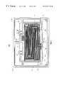
- FIG. 3is an enlarged view of the back face of the anode fluid flow plate of FIG. 2 about section B;
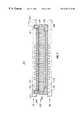
- FIG. 6is a cross-sectional view along sectional line 6 — 6 of the fluid flow plate of FIG. 5;
- FIG. 8is an expanded view about section A the PEM-type cell of FIG. 7 under compressive pressure.
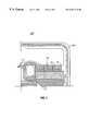
- PEM-type fuel cell 300includes a membrane electrode assembly 310 (hereinafter“MEA”) sandwiched between a cathode gas diffusion layer 312 ′ (hereafter “GDL”) which is in turn sandwiched between an anode assembly 80 and a cathode assembly 90 .
- Anode assembly 80includes a fluid flow plate 200 and compressible insulator 199 .
- Cathode assembly 90includes a fluid flow plate 200 ′ and a gasket 110 disposed within groove 95 .
- a membrane electrolyte 306 of MEA 310extends just beyond the fluid flow regions 212 and 212 ′ of the fluid flow plates such that the membrane electrolyte rests between gasket 110 and compressible member 199 .
- MEA 310also includes an anode catalyst 308 and a cathode catalyst 308 ′.
- Fluid flow platesmay be formed in accordance with the principles of U.S. application Ser. No. 09/054,670 by Carlstrom (entitled“Easily-Formable Fuel Cell Assembly Fluid Flow Plate Having Conductivity and Increased Non-Conductive Material,” filed Apr. 3, 1998, and assigned to Plug Power, L.L.C.), which is hereby incorporated herein by reference in its entirety.
- Fluid flow platesinclude bipolar, monopolar, combined monopolar (e.g., anode cooler or cathode cooler), or cooler plates.
- a back face of the platesupplies cooling to the stack and a front face of the plate acts as either an anode or a cathode.
- a bipolar plateincludes channels on both a front face and a back face.
- the front faceacts as a cathode for one PEM-type cell and the back face acts as an anode for an adjacent PEM-type cell.
- channels on the front faceconduct oxidant and waste product and the channels on the back face conduct fuel.
- the flow channelscan be connected directly to the supply and exhaust holes.
- bridge plates or cover platesare used between the flow channels and the compressible material and the gasket.
- the bridge or cover platesprohibit the compressible material and the gasket from clogging the inlet and outlet ends of the fluid flow channels when the PEM-type cell is compressed. Examples of fuel cells including bridge plates or cover plates is disclosed in U.S. application Ser. No. 08/899,262 which is incorporated herein by reference.
Landscapes
- Life Sciences & Earth Sciences (AREA)
- Engineering & Computer Science (AREA)
- Manufacturing & Machinery (AREA)
- Sustainable Development (AREA)
- Sustainable Energy (AREA)
- Chemical & Material Sciences (AREA)
- Chemical Kinetics & Catalysis (AREA)
- Electrochemistry (AREA)
- General Chemical & Material Sciences (AREA)
- Fuel Cell (AREA)
Abstract
Description
| Inlet B/S | Outlet B/S | ||
| Hydrogen-Air | 0.035 | <0.01 | ||
| Hydrogen-Coolant | 0.23 | <0.01 | ||
| Air-Coolant | 0.013 | <0.01 | ||
| Inlet B/S | Outlet B/S | ||
| Hydrogen-Air | 0.299 | 0.233 | ||
| Hydrogen-Coolant | 0.205 | 0.018 | ||
| Air-Coolant | 0.300 | 0.163 | ||
Claims (21)
Priority Applications (1)
| Application Number | Priority Date | Filing Date | Title |
|---|---|---|---|
| US09/396,158US6261711B1 (en) | 1999-09-14 | 1999-09-14 | Sealing system for fuel cells |
Applications Claiming Priority (1)
| Application Number | Priority Date | Filing Date | Title |
|---|---|---|---|
| US09/396,158US6261711B1 (en) | 1999-09-14 | 1999-09-14 | Sealing system for fuel cells |
Publications (1)
| Publication Number | Publication Date |
|---|---|
| US6261711B1true US6261711B1 (en) | 2001-07-17 |
Family
ID=23566097
Family Applications (1)
| Application Number | Title | Priority Date | Filing Date |
|---|---|---|---|
| US09/396,158Expired - LifetimeUS6261711B1 (en) | 1999-09-14 | 1999-09-14 | Sealing system for fuel cells |
Country Status (1)
| Country | Link |
|---|---|
| US (1) | US6261711B1 (en) |
Cited By (67)
| Publication number | Priority date | Publication date | Assignee | Title |
|---|---|---|---|---|
| US20020051901A1 (en)* | 2000-08-31 | 2002-05-02 | Ralf Zuber | PEM fuel cell stack |
| US20020110720A1 (en)* | 2001-02-15 | 2002-08-15 | Asia Pacific Fuel Cell Technologies, Ltd. | Modulized single cell and assembled cell unit of a proton exchange membrane fuel cell |
| US20020127461A1 (en)* | 2001-03-09 | 2002-09-12 | Honda Giken Kogyo Kabushiki Kaisha | Fuel cell and fuel cell stack |
| US20020172852A1 (en)* | 2001-05-15 | 2002-11-21 | David Frank | Flow field plate for a fuel cell and fuel cell assembly incorporating the flow field plate |
| US20020177026A1 (en)* | 2001-04-23 | 2002-11-28 | Nissan Motor Co., Ltd. | Solid oxide electrolyte fuel cell plate structure, stack and electrical power generation unit |
| US20030003342A1 (en)* | 2001-06-29 | 2003-01-02 | Honda Giken Kogyo Kabushiki Kaisha | Membrane electrode assembly, and fuel cell unit |
| US20030027032A1 (en)* | 2001-07-10 | 2003-02-06 | Honda Giken Kogyo Kabushiki Kaisha | Membrane electrode assembly and fuel cell unit |
| US20030072988A1 (en)* | 2001-10-16 | 2003-04-17 | Lawrence Eugene Frisch | Seals for fuel cells and fuel cell stacks |
| US6602632B2 (en)* | 2000-11-06 | 2003-08-05 | Honda Giken Kogyo Kabushiki Kaisha | Sealing member for fuel cell |
| US20030203267A1 (en)* | 2002-04-26 | 2003-10-30 | Yeong-Shyung Chou | Multi-layer seal for electrochemical devices |
| US6649097B2 (en)* | 1998-06-26 | 2003-11-18 | Nok Corporation | Method of making a gasket for layer-built fuel cells |
| US20030215690A1 (en)* | 2002-05-17 | 2003-11-20 | 3M Innovative Properties Company | Membrane electrode assembly with compression control gasket |
| US20030219641A1 (en)* | 2002-02-19 | 2003-11-27 | Petillo Phillip J. | Fuel cell components |
| US6667124B2 (en)* | 2000-07-19 | 2003-12-23 | Honda Giken Kogyo Kabushiki Kaisha | Seal for fuel cell and forming method therefor |
| US6716551B2 (en)* | 2001-05-02 | 2004-04-06 | Ballard Power Systems Inc. | Abraded fluid diffusion layer for an electrochemical fuel cell |
| US6720103B1 (en)* | 1999-09-01 | 2004-04-13 | Nok Corporation | Fuel cell |
| US20040096723A1 (en)* | 2002-11-14 | 2004-05-20 | 3M Innovative Properties Company | Fuel cell gasket |
| US6783883B1 (en)* | 1998-06-30 | 2004-08-31 | Manhattan Scientifics, Inc. | Gas-proof assembly composed of a bipolar plate and a membrane-electrode unit of polymer electrolyte membrane fuel cells |
| US20040185322A1 (en)* | 2003-01-30 | 2004-09-23 | Honda Motor Co., Ltd. | Fuel cell |
| US20040209148A1 (en)* | 2003-03-14 | 2004-10-21 | Matsushita Electric Industrial Co., Ltd. | Polymer electrolyte fuel cell |
| US20050019646A1 (en)* | 2003-05-16 | 2005-01-27 | Joos Nathaniel Ian | Complementary active-surface feed flow |
| WO2005018033A1 (en)* | 2003-08-15 | 2005-02-24 | Hydrogenics Corporation | Flow field plate arrangement |
| US20050064272A1 (en)* | 2001-05-15 | 2005-03-24 | Hydrogenics Corporation | Fuel cell flow field plate |
| US20050089745A1 (en)* | 2001-03-09 | 2005-04-28 | Honda Giken Kogyo Kabushiki Kaisha | Fuel cell and fuel cell stack |
| US20050095492A1 (en)* | 2001-05-15 | 2005-05-05 | Hydrogenics Corporation | Fuel cell stack |
| US20050112449A1 (en)* | 2003-11-24 | 2005-05-26 | Mark Mathias | Proton exchange membrane fuel cell |
| US20050115825A1 (en)* | 2003-09-22 | 2005-06-02 | David Frank | Electrolyzer cell arrangement |
| US20050173833A1 (en)* | 2004-02-05 | 2005-08-11 | Dale Cummins | Method of forming bipolar plate modules |
| WO2005036670A3 (en)* | 2003-09-17 | 2005-08-11 | Gen Motors Corp | Addressing one mea failure mode by controlling mea catalyst layer overlap |
| US20050181267A1 (en)* | 2002-10-29 | 2005-08-18 | Naoki Mitsuta | Membrane-electrode structure and method for producing the same |
| US20050183948A1 (en)* | 2003-09-22 | 2005-08-25 | Ali Rusta-Sallehy | Apparatus and method for reducing instances of pump de-priming |
| US20050186458A1 (en)* | 2003-09-22 | 2005-08-25 | Ali Rusta-Sallehy | Electrolyzer cell stack system |
| US20050249997A1 (en)* | 2004-02-23 | 2005-11-10 | Norihiro Tomimatsu | Fuel cell |
| US6974647B2 (en) | 1997-05-01 | 2005-12-13 | Ballard Power Systems Inc. | Fuel cell fluid distribution layer having integral sealing capability |
| US20050287414A1 (en)* | 2004-06-23 | 2005-12-29 | Noh Hyung-Gon | Fuel cell, and a method for preparing the same |
| US20060063659A1 (en)* | 2004-09-21 | 2006-03-23 | General Electric Company | Alkali-Free Composite Sealant Materials for Solid Oxide Fuel Cells |
| US20060068263A1 (en)* | 2003-06-02 | 2006-03-30 | Kim Ho-Suk | Sealing structure for polymer electrolyte fuel cell |
| US20060073373A1 (en)* | 2004-05-28 | 2006-04-06 | Peter Andrin | Unitized electrochemical cell sub-assembly and the method of making the same |
| US20060127737A1 (en)* | 2001-05-15 | 2006-06-15 | Frank David G | Apparatus for and method of forming seals in fuel cells and fuel stacks |
| US20060147785A1 (en)* | 2004-12-30 | 2006-07-06 | Industrial Technology Research Institute | Fuel cell |
| US7087339B2 (en) | 2002-05-10 | 2006-08-08 | 3M Innovative Properties Company | Fuel cell membrane electrode assembly with sealing surfaces |
| US20060210857A1 (en)* | 2005-03-15 | 2006-09-21 | David Frank | Electrochemical cell arrangement with improved mea-coolant manifold isolation |
| US20060210855A1 (en)* | 2005-03-15 | 2006-09-21 | David Frank | Flow field plate arrangement |
| US20070003816A1 (en)* | 2005-06-22 | 2007-01-04 | Honda Motor Co., Ltd. | Fuel cell and separator for fuel cell |
| US20070020506A1 (en)* | 2004-12-30 | 2007-01-25 | Haltiner Karl J Jr | Modular fuel cell cassette spacers for forming a solid-oxide fuel cell stack |
| US20070042261A1 (en)* | 2003-03-28 | 2007-02-22 | Katsuhiko Kohyama | Solid polymer electrolyte fuel cell and electrode structure for the fuel cell |
| US20070154760A1 (en)* | 2005-12-30 | 2007-07-05 | Yimin Zhu | Composite polymer electrolyte membranes and electrode assemblies for reducing fuel crossover in direct liquid feed fuel cells |
| US20080118802A1 (en)* | 2006-11-16 | 2008-05-22 | Peter Szrama | Fully Catalyzed Membrane Assembly With Attached Border |
| DE102006059857A1 (en)* | 2006-12-15 | 2008-06-19 | Behr Gmbh & Co. Kg | Bipolar plate for fuel cell stack, has individual disk part with electric flow current whose upper side and lower side has inflow area and outflow area |
| US20080248357A1 (en)* | 2006-06-20 | 2008-10-09 | Takahiro Terada | Fuel cell seal and fuel cell |
| CN100468831C (en)* | 2005-06-16 | 2009-03-11 | 鸿富锦精密工业(深圳)有限公司 | Seal structure of fuel cell |
| US20090246599A1 (en)* | 2008-03-28 | 2009-10-01 | Gm Global Technology Operations, Inc. | Tunnel bridge with elastomeric seal for a fuel cell stack repeating unit |
| WO2010080450A1 (en) | 2008-12-19 | 2010-07-15 | Ballard Power Systems Inc. | Seal for solid polymer electrolyte fuel cell |
| US20110177423A1 (en)* | 2010-01-21 | 2011-07-21 | Anton Nachtmann | Five-Layer Membrane Electrode Assembly with Attached Border and Method of Making Same |
| US8177884B2 (en) | 2009-05-20 | 2012-05-15 | United Technologies Corporation | Fuel deoxygenator with porous support plate |
| US20130052565A1 (en)* | 2010-05-12 | 2013-02-28 | Utc Power Corporation | Applying a seal to a fuel cell component |
| JP2013168353A (en)* | 2012-01-16 | 2013-08-29 | Honda Motor Co Ltd | Electrolyte membrane-electrode structure equipped with fuel cell resin frame |
| EP2525429A4 (en)* | 2010-01-14 | 2014-01-01 | Honda Motor Co Ltd | Fuel cell |
| US20140134514A1 (en)* | 2011-10-05 | 2014-05-15 | Ngk Insulators, Ltd. | Fuel cell |
| CN103988351A (en)* | 2011-12-06 | 2014-08-13 | 丰田自动车株式会社 | Fuel cell |
| US9803288B2 (en)* | 2012-07-24 | 2017-10-31 | Nuvera Fuel Cells, LLC | Arrangement of flow structures for use in high differential pressure electrochemical cells |
| US20180102555A1 (en)* | 2016-10-12 | 2018-04-12 | Hyundai Motor Company | Gasket for fuel cell |
| US20180264690A1 (en)* | 2015-01-16 | 2018-09-20 | Areva Stockage D'energie | Method for producing seals on electrochemical reactor components |
| US20190221865A1 (en)* | 2018-01-17 | 2019-07-18 | Nuvera Fuel Cells, LLC | Fuel-cell plate and flow structure designs |
| WO2020007048A1 (en)* | 2018-07-04 | 2020-01-09 | 上海旭济动力科技有限公司 | Fuel cell having fluid guide flow path and manufacturing method therefor |
| US11289728B2 (en) | 2017-09-01 | 2022-03-29 | Stryten Critical E-Storage Llc | Segmented frames for redox flow batteries |
| EP4089204A4 (en)* | 2020-01-08 | 2024-11-20 | Panasonic Intellectual Property Management Co., Ltd. | COMPRESSION DEVICE |
Citations (43)
| Publication number | Priority date | Publication date | Assignee | Title |
|---|---|---|---|---|
| US4169917A (en) | 1978-07-10 | 1979-10-02 | Energy Research Corporation | Electrochemical cell and separator plate thereof |
| US4269642A (en) | 1979-10-29 | 1981-05-26 | United Technologies Corporation | Method of forming densified edge seals for fuel cell components |
| EP0041294A1 (en) | 1980-05-31 | 1981-12-09 | Electrochemische Energieconversie N.V. | Apparatus for supplying or draining a fluid to or from the marginal portion of a flat fuel cell electrode and an electrode element and a fuel cell provided with such an apparatus |
| US4365008A (en) | 1981-07-27 | 1982-12-21 | United Technologies Corporation | Densified edge seals for fuel cell components |
| US4505992A (en) | 1983-04-11 | 1985-03-19 | Engelhard Corporation | Integral gas seal for fuel cell gas distribution assemblies and method of fabrication |
| US4588661A (en) | 1984-08-27 | 1986-05-13 | Engelhard Corporation | Fabrication of gas impervious edge seal for a bipolar gas distribution assembly for use in a fuel cell |
| US4604331A (en) | 1984-05-29 | 1986-08-05 | The United States Of America As Represented By The United States Department Of Energy | Fuel cell separator plate with bellows-type sealing flanges |
| US4738905A (en) | 1986-12-03 | 1988-04-19 | International Fuel Cells Corporation | Manifold seal structure for fuel cell stack |
| US4774154A (en) | 1986-09-22 | 1988-09-27 | International Fuel Cells | Expanded high-temperature stable chemical resistant seal material |
| US4795536A (en) | 1985-07-10 | 1989-01-03 | Allied-Signal Inc. | Hydrogen separation and electricity generation using novel three-component membrane |
| US4797185A (en) | 1985-07-19 | 1989-01-10 | Allied-Signal Inc. | Hydrogen separation and electricity generation using novel electrolyte membrane |
| US4824741A (en) | 1988-02-12 | 1989-04-25 | International Fuel Cells Corporation | Solid polymer electrolyte fuel cell system with porous plate evaporative cooling |
| US4973530A (en) | 1989-12-21 | 1990-11-27 | The United States Of America As Represented By The United States Department Of Energy | Fuel cell water transport |
| US4988583A (en) | 1989-08-30 | 1991-01-29 | Her Majesty The Queen As Represented By The Minister Of National Defence Of Her Majesty's Canadian Government | Novel fuel cell fluid flow field plate |
| US5110691A (en) | 1991-01-16 | 1992-05-05 | International Fuel Cells Corporation | Fuel cell component sealant |
| US5176966A (en) | 1990-11-19 | 1993-01-05 | Ballard Power Systems Inc. | Fuel cell membrane electrode and seal assembly |
| US5219674A (en) | 1991-12-26 | 1993-06-15 | International Fuel Cells Corporation | Sealant for porous fuel cell component frames using polymerization of monomers |
| US5230966A (en) | 1991-09-26 | 1993-07-27 | Ballard Power Systems Inc. | Coolant flow field plate for electrochemical fuel cells |
| US5262249A (en) | 1991-12-26 | 1993-11-16 | International Fuel Cells Corporation | Internally cooled proton exchange membrane fuel cell device |
| US5262250A (en) | 1991-02-14 | 1993-11-16 | Tanaka Kikinzoku Kogyo K.K. | Structure of electrochemical cell for wetting diaphragm of solid polymer electrolyte |
| US5264299A (en) | 1991-12-26 | 1993-11-23 | International Fuel Cells Corporation | Proton exchange membrane fuel cell support plate and an assembly including the same |
| US5284718A (en)* | 1991-09-27 | 1994-02-08 | Ballard Power Systems Inc. | Fuel cell membrane electrode and seal assembly |
| US5300370A (en) | 1992-11-13 | 1994-04-05 | Ballard Power Systems Inc. | Laminated fluid flow field assembly for electrochemical fuel cells |
| US5382478A (en) | 1992-11-03 | 1995-01-17 | Ballard Power Systems Inc. | Electrochemical fuel cell stack with humidification section located upstream from the electrochemically active section |
| US5432021A (en) | 1992-10-09 | 1995-07-11 | Ballard Power Systems Inc. | Method and apparatus for oxidizing carbon monoxide in the reactant stream of an electrochemical fuel cell |
| US5441621A (en) | 1993-12-22 | 1995-08-15 | United Technologies Corporation | Electrochemical cell having crossed-ridge sealing surface |
| US5464700A (en) | 1991-06-04 | 1995-11-07 | Ballard Power Systems Inc. | Gasketed membrane electrode assembly for electrochemical fuel cells |
| US5482680A (en) | 1992-10-09 | 1996-01-09 | Ballard Power Systems, Inc. | Electrochemical fuel cell assembly with integral selective oxidizer |
| US5523175A (en) | 1991-12-26 | 1996-06-04 | International Fuel Cells Corporation | Plate-shaped fuel cell component |
| US5529855A (en) | 1992-12-24 | 1996-06-25 | Tanaka Kikinzoku Kogyo K.K. | Structure for wetting diaphragm of solid polymer electolyte electrochemical cell and process of preparing same |
| US5547776A (en) | 1991-01-15 | 1996-08-20 | Ballard Power Systems Inc. | Electrochemical fuel cell stack with concurrently flowing coolant and oxidant streams |
| US5733682A (en) | 1994-03-28 | 1998-03-31 | Forschungszentrum Julich Gmbh | Metallic bipolar plate for high-temperature fuel cells and method of making same |
| US5773160A (en) | 1994-06-24 | 1998-06-30 | Ballard Power Systems Inc. | Electrochemical fuel cell stack with concurrent flow of coolant and oxidant streams and countercurrent flow of fuel and oxidant streams |
| US5789094A (en) | 1994-01-27 | 1998-08-04 | Kansai Electric Power Co., Inc. | Fuel cell and sealing parts therefore |
| US5840414A (en) | 1996-11-15 | 1998-11-24 | International Fuel Cells, Inc. | Porous carbon body with increased wettability by water |
| US5853909A (en) | 1995-06-23 | 1998-12-29 | International Fuel Cells, Llc | Ion exchange membrane fuel cell power plant with water management pressure differentials |
| US5858567A (en) | 1994-10-12 | 1999-01-12 | H Power Corporation | Fuel cells employing integrated fluid management platelet technology |
| US5863671A (en) | 1994-10-12 | 1999-01-26 | H Power Corporation | Plastic platelet fuel cells employing integrated fluid management |
| US5928807A (en)* | 1995-11-15 | 1999-07-27 | Ballard Power Systems Inc. | Integrated seal for a PEM fuel cell |
| US6007931A (en) | 1998-06-24 | 1999-12-28 | International Fuel Cells Corporation | Mass and heat recovery system for a fuel cell power plant |
| US6013385A (en) | 1997-07-25 | 2000-01-11 | Emprise Corporation | Fuel cell gas management system |
| US6057054A (en)* | 1997-07-16 | 2000-05-02 | Ballard Power Systems Inc. | Membrane electrode assembly for an electrochemical fuel cell and a method of making an improved membrane electrode assembly |
| JP2000133288A (en)* | 1998-10-28 | 2000-05-12 | Nok Corp | Carbon material for fuel cell |
- 1999
- 1999-09-14USUS09/396,158patent/US6261711B1/ennot_activeExpired - Lifetime
Patent Citations (43)
| Publication number | Priority date | Publication date | Assignee | Title |
|---|---|---|---|---|
| US4169917A (en) | 1978-07-10 | 1979-10-02 | Energy Research Corporation | Electrochemical cell and separator plate thereof |
| US4269642A (en) | 1979-10-29 | 1981-05-26 | United Technologies Corporation | Method of forming densified edge seals for fuel cell components |
| EP0041294A1 (en) | 1980-05-31 | 1981-12-09 | Electrochemische Energieconversie N.V. | Apparatus for supplying or draining a fluid to or from the marginal portion of a flat fuel cell electrode and an electrode element and a fuel cell provided with such an apparatus |
| US4365008A (en) | 1981-07-27 | 1982-12-21 | United Technologies Corporation | Densified edge seals for fuel cell components |
| US4505992A (en) | 1983-04-11 | 1985-03-19 | Engelhard Corporation | Integral gas seal for fuel cell gas distribution assemblies and method of fabrication |
| US4604331A (en) | 1984-05-29 | 1986-08-05 | The United States Of America As Represented By The United States Department Of Energy | Fuel cell separator plate with bellows-type sealing flanges |
| US4588661A (en) | 1984-08-27 | 1986-05-13 | Engelhard Corporation | Fabrication of gas impervious edge seal for a bipolar gas distribution assembly for use in a fuel cell |
| US4795536A (en) | 1985-07-10 | 1989-01-03 | Allied-Signal Inc. | Hydrogen separation and electricity generation using novel three-component membrane |
| US4797185A (en) | 1985-07-19 | 1989-01-10 | Allied-Signal Inc. | Hydrogen separation and electricity generation using novel electrolyte membrane |
| US4774154A (en) | 1986-09-22 | 1988-09-27 | International Fuel Cells | Expanded high-temperature stable chemical resistant seal material |
| US4738905A (en) | 1986-12-03 | 1988-04-19 | International Fuel Cells Corporation | Manifold seal structure for fuel cell stack |
| US4824741A (en) | 1988-02-12 | 1989-04-25 | International Fuel Cells Corporation | Solid polymer electrolyte fuel cell system with porous plate evaporative cooling |
| US4988583A (en) | 1989-08-30 | 1991-01-29 | Her Majesty The Queen As Represented By The Minister Of National Defence Of Her Majesty's Canadian Government | Novel fuel cell fluid flow field plate |
| US4973530A (en) | 1989-12-21 | 1990-11-27 | The United States Of America As Represented By The United States Department Of Energy | Fuel cell water transport |
| US5176966A (en) | 1990-11-19 | 1993-01-05 | Ballard Power Systems Inc. | Fuel cell membrane electrode and seal assembly |
| US5547776A (en) | 1991-01-15 | 1996-08-20 | Ballard Power Systems Inc. | Electrochemical fuel cell stack with concurrently flowing coolant and oxidant streams |
| US5110691A (en) | 1991-01-16 | 1992-05-05 | International Fuel Cells Corporation | Fuel cell component sealant |
| US5262250A (en) | 1991-02-14 | 1993-11-16 | Tanaka Kikinzoku Kogyo K.K. | Structure of electrochemical cell for wetting diaphragm of solid polymer electrolyte |
| US5464700A (en) | 1991-06-04 | 1995-11-07 | Ballard Power Systems Inc. | Gasketed membrane electrode assembly for electrochemical fuel cells |
| US5230966A (en) | 1991-09-26 | 1993-07-27 | Ballard Power Systems Inc. | Coolant flow field plate for electrochemical fuel cells |
| US5284718A (en)* | 1991-09-27 | 1994-02-08 | Ballard Power Systems Inc. | Fuel cell membrane electrode and seal assembly |
| US5523175A (en) | 1991-12-26 | 1996-06-04 | International Fuel Cells Corporation | Plate-shaped fuel cell component |
| US5262249A (en) | 1991-12-26 | 1993-11-16 | International Fuel Cells Corporation | Internally cooled proton exchange membrane fuel cell device |
| US5264299A (en) | 1991-12-26 | 1993-11-23 | International Fuel Cells Corporation | Proton exchange membrane fuel cell support plate and an assembly including the same |
| US5219674A (en) | 1991-12-26 | 1993-06-15 | International Fuel Cells Corporation | Sealant for porous fuel cell component frames using polymerization of monomers |
| US5432021A (en) | 1992-10-09 | 1995-07-11 | Ballard Power Systems Inc. | Method and apparatus for oxidizing carbon monoxide in the reactant stream of an electrochemical fuel cell |
| US5482680A (en) | 1992-10-09 | 1996-01-09 | Ballard Power Systems, Inc. | Electrochemical fuel cell assembly with integral selective oxidizer |
| US5382478A (en) | 1992-11-03 | 1995-01-17 | Ballard Power Systems Inc. | Electrochemical fuel cell stack with humidification section located upstream from the electrochemically active section |
| US5300370A (en) | 1992-11-13 | 1994-04-05 | Ballard Power Systems Inc. | Laminated fluid flow field assembly for electrochemical fuel cells |
| US5529855A (en) | 1992-12-24 | 1996-06-25 | Tanaka Kikinzoku Kogyo K.K. | Structure for wetting diaphragm of solid polymer electolyte electrochemical cell and process of preparing same |
| US5441621A (en) | 1993-12-22 | 1995-08-15 | United Technologies Corporation | Electrochemical cell having crossed-ridge sealing surface |
| US5789094A (en) | 1994-01-27 | 1998-08-04 | Kansai Electric Power Co., Inc. | Fuel cell and sealing parts therefore |
| US5733682A (en) | 1994-03-28 | 1998-03-31 | Forschungszentrum Julich Gmbh | Metallic bipolar plate for high-temperature fuel cells and method of making same |
| US5773160A (en) | 1994-06-24 | 1998-06-30 | Ballard Power Systems Inc. | Electrochemical fuel cell stack with concurrent flow of coolant and oxidant streams and countercurrent flow of fuel and oxidant streams |
| US5858567A (en) | 1994-10-12 | 1999-01-12 | H Power Corporation | Fuel cells employing integrated fluid management platelet technology |
| US5863671A (en) | 1994-10-12 | 1999-01-26 | H Power Corporation | Plastic platelet fuel cells employing integrated fluid management |
| US5853909A (en) | 1995-06-23 | 1998-12-29 | International Fuel Cells, Llc | Ion exchange membrane fuel cell power plant with water management pressure differentials |
| US5928807A (en)* | 1995-11-15 | 1999-07-27 | Ballard Power Systems Inc. | Integrated seal for a PEM fuel cell |
| US5840414A (en) | 1996-11-15 | 1998-11-24 | International Fuel Cells, Inc. | Porous carbon body with increased wettability by water |
| US6057054A (en)* | 1997-07-16 | 2000-05-02 | Ballard Power Systems Inc. | Membrane electrode assembly for an electrochemical fuel cell and a method of making an improved membrane electrode assembly |
| US6013385A (en) | 1997-07-25 | 2000-01-11 | Emprise Corporation | Fuel cell gas management system |
| US6007931A (en) | 1998-06-24 | 1999-12-28 | International Fuel Cells Corporation | Mass and heat recovery system for a fuel cell power plant |
| JP2000133288A (en)* | 1998-10-28 | 2000-05-12 | Nok Corp | Carbon material for fuel cell |
Cited By (130)
| Publication number | Priority date | Publication date | Assignee | Title |
|---|---|---|---|---|
| US6974647B2 (en) | 1997-05-01 | 2005-12-13 | Ballard Power Systems Inc. | Fuel cell fluid distribution layer having integral sealing capability |
| US6649097B2 (en)* | 1998-06-26 | 2003-11-18 | Nok Corporation | Method of making a gasket for layer-built fuel cells |
| US6783883B1 (en)* | 1998-06-30 | 2004-08-31 | Manhattan Scientifics, Inc. | Gas-proof assembly composed of a bipolar plate and a membrane-electrode unit of polymer electrolyte membrane fuel cells |
| US6720103B1 (en)* | 1999-09-01 | 2004-04-13 | Nok Corporation | Fuel cell |
| US6667124B2 (en)* | 2000-07-19 | 2003-12-23 | Honda Giken Kogyo Kabushiki Kaisha | Seal for fuel cell and forming method therefor |
| US6720104B2 (en)* | 2000-08-31 | 2004-04-13 | Dmc2 Degussa Metals Catalysts Cerdec Ag | PEM fuel cell stack |
| US20020051901A1 (en)* | 2000-08-31 | 2002-05-02 | Ralf Zuber | PEM fuel cell stack |
| US6602632B2 (en)* | 2000-11-06 | 2003-08-05 | Honda Giken Kogyo Kabushiki Kaisha | Sealing member for fuel cell |
| US20020110720A1 (en)* | 2001-02-15 | 2002-08-15 | Asia Pacific Fuel Cell Technologies, Ltd. | Modulized single cell and assembled cell unit of a proton exchange membrane fuel cell |
| US20050089745A1 (en)* | 2001-03-09 | 2005-04-28 | Honda Giken Kogyo Kabushiki Kaisha | Fuel cell and fuel cell stack |
| US7297432B2 (en) | 2001-03-09 | 2007-11-20 | Honda Giken Kogyo Kabushiki Kaisha | Fuel cell and fuel cell stack |
| US20020127461A1 (en)* | 2001-03-09 | 2002-09-12 | Honda Giken Kogyo Kabushiki Kaisha | Fuel cell and fuel cell stack |
| US6815115B2 (en)* | 2001-03-09 | 2004-11-09 | Honda Giken Kogyo Kabushiki Kaisha | Fuel cell and fuel cell stack |
| US8323845B2 (en) | 2001-04-23 | 2012-12-04 | Nissan Motor Co., Ltd. | Solid oxide electrolyte fuel cell plate structure, stack and electrical power generation unit |
| US7122268B2 (en)* | 2001-04-23 | 2006-10-17 | Nissan Motor Co., Ltd. | Solid oxide electrolyte fuel cell plate structure, stack and electrical power generation unit |
| US20020177026A1 (en)* | 2001-04-23 | 2002-11-28 | Nissan Motor Co., Ltd. | Solid oxide electrolyte fuel cell plate structure, stack and electrical power generation unit |
| US20060269822A1 (en)* | 2001-04-23 | 2006-11-30 | Nissan Motor Co., Ltd. | Solid oxide electrolyte fuel cell plate structure, stack and electrical power generation unit |
| US6716551B2 (en)* | 2001-05-02 | 2004-04-06 | Ballard Power Systems Inc. | Abraded fluid diffusion layer for an electrochemical fuel cell |
| US20050095492A1 (en)* | 2001-05-15 | 2005-05-05 | Hydrogenics Corporation | Fuel cell stack |
| US20050064272A1 (en)* | 2001-05-15 | 2005-03-24 | Hydrogenics Corporation | Fuel cell flow field plate |
| US20020172852A1 (en)* | 2001-05-15 | 2002-11-21 | David Frank | Flow field plate for a fuel cell and fuel cell assembly incorporating the flow field plate |
| US20060127737A1 (en)* | 2001-05-15 | 2006-06-15 | Frank David G | Apparatus for and method of forming seals in fuel cells and fuel stacks |
| US7201987B2 (en)* | 2001-06-29 | 2007-04-10 | Honda Giken Kogyo Kabushiki Kaisha | Membrane electrode assembly, and fuel cell unit |
| US20030003342A1 (en)* | 2001-06-29 | 2003-01-02 | Honda Giken Kogyo Kabushiki Kaisha | Membrane electrode assembly, and fuel cell unit |
| US7056614B2 (en)* | 2001-07-10 | 2006-06-06 | Honda Giken Kogyo Kabushiki Kaisha | Membrane electrode assembly and fuel cell unit |
| US20030027032A1 (en)* | 2001-07-10 | 2003-02-06 | Honda Giken Kogyo Kabushiki Kaisha | Membrane electrode assembly and fuel cell unit |
| US6761991B2 (en) | 2001-10-16 | 2004-07-13 | Dow Corning Corporation | Seals for fuel cells and fuel cell stacks |
| US20030072988A1 (en)* | 2001-10-16 | 2003-04-17 | Lawrence Eugene Frisch | Seals for fuel cells and fuel cell stacks |
| US6998188B2 (en) | 2002-02-19 | 2006-02-14 | Petillo Phillip J | Fuel cell components |
| US20030219641A1 (en)* | 2002-02-19 | 2003-11-27 | Petillo Phillip J. | Fuel cell components |
| US7794894B2 (en) | 2002-04-26 | 2010-09-14 | Battelle Memorial Institute | Multi-layer seal for electrochemical devices |
| US20070259248A1 (en)* | 2002-04-26 | 2007-11-08 | Battelle Memorial Institute | Multi-layer seal for electrochemical devices |
| US20060012135A1 (en)* | 2002-04-26 | 2006-01-19 | Battelle Memorial Institute | Multi-layer seal for electrochemical devices |
| US20030203267A1 (en)* | 2002-04-26 | 2003-10-30 | Yeong-Shyung Chou | Multi-layer seal for electrochemical devices |
| US7832737B2 (en) | 2002-04-26 | 2010-11-16 | Battelle Memorial Institute | Multi-layer seal for electrochemical devices |
| US7222406B2 (en) | 2002-04-26 | 2007-05-29 | Battelle Memorial Institute | Methods for making a multi-layer seal for electrochemical devices |
| US20060233948A1 (en)* | 2002-05-10 | 2006-10-19 | 3M Innovative Properties Company | Fuel cell membrane electrode assembly with sealing surfaces |
| US7087339B2 (en) | 2002-05-10 | 2006-08-08 | 3M Innovative Properties Company | Fuel cell membrane electrode assembly with sealing surfaces |
| US7553578B2 (en) | 2002-05-10 | 2009-06-30 | 3M Innovative Properties Company | Fuel cell membrane electrode assembly with sealing surfaces |
| US8343682B2 (en) | 2002-05-17 | 2013-01-01 | 3M Innovative Properties Company | Membrane electrode assembly with compression control gasket |
| US20030215690A1 (en)* | 2002-05-17 | 2003-11-20 | 3M Innovative Properties Company | Membrane electrode assembly with compression control gasket |
| US7217471B2 (en) | 2002-05-17 | 2007-05-15 | 3M Innovative Properties Company | Membrane electrode assembly with compression control gasket |
| US20070178354A1 (en)* | 2002-05-17 | 2007-08-02 | 3M Innovation Properties Company | Membrane electrode assembly with compression control gasket |
| US20050181267A1 (en)* | 2002-10-29 | 2005-08-18 | Naoki Mitsuta | Membrane-electrode structure and method for producing the same |
| US20040096723A1 (en)* | 2002-11-14 | 2004-05-20 | 3M Innovative Properties Company | Fuel cell gasket |
| US20040185322A1 (en)* | 2003-01-30 | 2004-09-23 | Honda Motor Co., Ltd. | Fuel cell |
| US7351490B2 (en)* | 2003-01-30 | 2008-04-01 | Honda Motor Co., Ltd. | Fuel cell |
| EP1458040A3 (en)* | 2003-03-14 | 2007-02-28 | Matsushita Electric Industrial Co., Ltd. | Fuel cell |
| US7405019B2 (en) | 2003-03-14 | 2008-07-29 | Matsushita Electric Industrial Co., Ltd. | Polymer electrolyte fuel cell |
| US20040209148A1 (en)* | 2003-03-14 | 2004-10-21 | Matsushita Electric Industrial Co., Ltd. | Polymer electrolyte fuel cell |
| US20070042261A1 (en)* | 2003-03-28 | 2007-02-22 | Katsuhiko Kohyama | Solid polymer electrolyte fuel cell and electrode structure for the fuel cell |
| US7776464B2 (en)* | 2003-03-28 | 2010-08-17 | Honda Motor Co., Ltd. | Solid polymer electrolyte fuel cell and electrode structure for the fuel cell |
| US20050019646A1 (en)* | 2003-05-16 | 2005-01-27 | Joos Nathaniel Ian | Complementary active-surface feed flow |
| US20050031936A1 (en)* | 2003-05-16 | 2005-02-10 | Joos Nathaniel Ian | Symmetrical flow field plates |
| US20060068263A1 (en)* | 2003-06-02 | 2006-03-30 | Kim Ho-Suk | Sealing structure for polymer electrolyte fuel cell |
| EP1649533A4 (en)* | 2003-06-02 | 2007-08-15 | Fuelcellpower Co Ltd | SEAL STRUCTURE FOR A POLYMER ELECTROLYTE FUEL CELL |
| US8420273B2 (en)* | 2003-06-02 | 2013-04-16 | Fuelcellpower Co., Ltd. | Sealing structure for polymer electrolyte fuel cell |
| US20050069749A1 (en)* | 2003-08-15 | 2005-03-31 | David Frank | Flow field plate arrangement |
| WO2005018033A1 (en)* | 2003-08-15 | 2005-02-24 | Hydrogenics Corporation | Flow field plate arrangement |
| DE112004001685B4 (en)* | 2003-09-17 | 2013-08-14 | General Motors Corp. | Device with a membrane electrode assembly and method for producing a membrane electrode assembly |
| US7132191B2 (en)* | 2003-09-17 | 2006-11-07 | General Motors Corporation | Addressing one MEA failure mode by controlling MEA catalyst layer overlap |
| CN1853295B (en)* | 2003-09-17 | 2010-06-09 | 通用汽车公司 | Addressing a MEA Failure Mode by Controlling MEA Catalyst Layer Overlap |
| WO2005036670A3 (en)* | 2003-09-17 | 2005-08-11 | Gen Motors Corp | Addressing one mea failure mode by controlling mea catalyst layer overlap |
| US20050115825A1 (en)* | 2003-09-22 | 2005-06-02 | David Frank | Electrolyzer cell arrangement |
| US20090071819A1 (en)* | 2003-09-22 | 2009-03-19 | Ali Rusta-Sallehy | Electrolyzer cell stack system |
| US20050186458A1 (en)* | 2003-09-22 | 2005-08-25 | Ali Rusta-Sallehy | Electrolyzer cell stack system |
| US8419910B2 (en) | 2003-09-22 | 2013-04-16 | Hydrogenics Corporation | Electrolyzer cell stack system |
| US20050197743A1 (en)* | 2003-09-22 | 2005-09-08 | Ali Rusta-Sallehy | Electrolyzer cell stack system |
| US20050260482A1 (en)* | 2003-09-22 | 2005-11-24 | David Frank | Flow field plate arrangement |
| US9580825B2 (en) | 2003-09-22 | 2017-02-28 | Hydrogenics Corporation | Electrolyzer cell stack system |
| US20050183948A1 (en)* | 2003-09-22 | 2005-08-25 | Ali Rusta-Sallehy | Apparatus and method for reducing instances of pump de-priming |
| US7353085B2 (en) | 2003-09-22 | 2008-04-01 | Hydrogenics Corporation | Electrolyzer cell stack system |
| WO2005057684A3 (en)* | 2003-11-24 | 2006-04-13 | Gen Motors Corp | Improved proton exchange membrane fuel cell |
| US20050112449A1 (en)* | 2003-11-24 | 2005-05-26 | Mark Mathias | Proton exchange membrane fuel cell |
| US7157178B2 (en)* | 2003-11-24 | 2007-01-02 | General Motors Corporation | Proton exchange membrane fuel cell |
| US20050173833A1 (en)* | 2004-02-05 | 2005-08-11 | Dale Cummins | Method of forming bipolar plate modules |
| US20050249997A1 (en)* | 2004-02-23 | 2005-11-10 | Norihiro Tomimatsu | Fuel cell |
| US7524573B2 (en)* | 2004-02-23 | 2009-04-28 | Kabushiki Kaisha Toshiba | Fuel cell having inner and outer periphery seal members |
| US20060073373A1 (en)* | 2004-05-28 | 2006-04-06 | Peter Andrin | Unitized electrochemical cell sub-assembly and the method of making the same |
| US20110294033A1 (en)* | 2004-05-28 | 2011-12-01 | E. I. Du Pont De Nemours And Company | Unitized electrochemical cell sub-assembly and the method of making the same |
| US20050287414A1 (en)* | 2004-06-23 | 2005-12-29 | Noh Hyung-Gon | Fuel cell, and a method for preparing the same |
| US7521387B2 (en) | 2004-09-21 | 2009-04-21 | General Electric Company | Alkali-free composite sealant materials for solid oxide fuel cells |
| US20060063659A1 (en)* | 2004-09-21 | 2006-03-23 | General Electric Company | Alkali-Free Composite Sealant Materials for Solid Oxide Fuel Cells |
| US7758989B2 (en) | 2004-12-30 | 2010-07-20 | Delphi Technologies, Inc. | Modular fuel cell cassette spacers for forming a solid-oxide fuel cell stack |
| US20060147785A1 (en)* | 2004-12-30 | 2006-07-06 | Industrial Technology Research Institute | Fuel cell |
| US20070020506A1 (en)* | 2004-12-30 | 2007-01-25 | Haltiner Karl J Jr | Modular fuel cell cassette spacers for forming a solid-oxide fuel cell stack |
| US20060210855A1 (en)* | 2005-03-15 | 2006-09-21 | David Frank | Flow field plate arrangement |
| US20060210857A1 (en)* | 2005-03-15 | 2006-09-21 | David Frank | Electrochemical cell arrangement with improved mea-coolant manifold isolation |
| CN100468831C (en)* | 2005-06-16 | 2009-03-11 | 鸿富锦精密工业(深圳)有限公司 | Seal structure of fuel cell |
| US7790326B2 (en)* | 2005-06-22 | 2010-09-07 | Honda Motor Co., Ltd. | Fuel cell and separator for fuel cell |
| US20070003816A1 (en)* | 2005-06-22 | 2007-01-04 | Honda Motor Co., Ltd. | Fuel cell and separator for fuel cell |
| US20070154760A1 (en)* | 2005-12-30 | 2007-07-05 | Yimin Zhu | Composite polymer electrolyte membranes and electrode assemblies for reducing fuel crossover in direct liquid feed fuel cells |
| US7368200B2 (en) | 2005-12-30 | 2008-05-06 | Tekion, Inc. | Composite polymer electrolyte membranes and electrode assemblies for reducing fuel crossover in direct liquid feed fuel cells |
| US20080248357A1 (en)* | 2006-06-20 | 2008-10-09 | Takahiro Terada | Fuel cell seal and fuel cell |
| WO2008039260A3 (en)* | 2006-09-27 | 2008-07-24 | Delphi Tech Inc | Modular fuel cell cassette spacers |
| US20080118802A1 (en)* | 2006-11-16 | 2008-05-22 | Peter Szrama | Fully Catalyzed Membrane Assembly With Attached Border |
| DE102006059857A1 (en)* | 2006-12-15 | 2008-06-19 | Behr Gmbh & Co. Kg | Bipolar plate for fuel cell stack, has individual disk part with electric flow current whose upper side and lower side has inflow area and outflow area |
| US20090246599A1 (en)* | 2008-03-28 | 2009-10-01 | Gm Global Technology Operations, Inc. | Tunnel bridge with elastomeric seal for a fuel cell stack repeating unit |
| US8298714B2 (en)* | 2008-03-28 | 2012-10-30 | GM Global Technology Operations LLC | Tunnel bridge with elastomeric seal for a fuel cell stack repeating unit |
| US20120034542A1 (en)* | 2008-12-19 | 2012-02-09 | Ballard Power Systems Inc. | Seal for solid polymer electrolyte fuel cell |
| WO2010080450A1 (en) | 2008-12-19 | 2010-07-15 | Ballard Power Systems Inc. | Seal for solid polymer electrolyte fuel cell |
| CN102257663A (en)* | 2008-12-19 | 2011-11-23 | 百拉得动力系统公司 | Seal for solid polymer electrolyte fuel cell |
| US9240598B2 (en)* | 2008-12-19 | 2016-01-19 | Ballard Power Systems Inc. | Seal for solid polymer electrolyte fuel cell |
| KR101500311B1 (en)* | 2008-12-19 | 2015-03-17 | 발라드 파워 시스템즈 인크. | Seal for solid polymer electrolyte fuel cell |
| US20150030960A1 (en)* | 2008-12-19 | 2015-01-29 | Ballard Power Systems Inc. | Seal for solid polymer electrolyte fuel cell |
| CN102257663B (en)* | 2008-12-19 | 2014-08-13 | 百拉得动力系统公司 | Seal for solid polymer electrolyte fuel cell |
| US8828617B2 (en)* | 2008-12-19 | 2014-09-09 | Ballard Power Systems Inc. | Seal for solid polymer electrolyte fuel cell |
| US8177884B2 (en) | 2009-05-20 | 2012-05-15 | United Technologies Corporation | Fuel deoxygenator with porous support plate |
| US9559376B2 (en) | 2010-01-14 | 2017-01-31 | Honda Motor Co., Ltd. | Fuel cell with an electrolyte membrane and gas diffusion layers |
| EP2525429A4 (en)* | 2010-01-14 | 2014-01-01 | Honda Motor Co Ltd | Fuel cell |
| US20110177423A1 (en)* | 2010-01-21 | 2011-07-21 | Anton Nachtmann | Five-Layer Membrane Electrode Assembly with Attached Border and Method of Making Same |
| US20130052565A1 (en)* | 2010-05-12 | 2013-02-28 | Utc Power Corporation | Applying a seal to a fuel cell component |
| US9312547B2 (en)* | 2010-05-12 | 2016-04-12 | Audi Ag | Applying a seal to a fuel cell component |
| US20140134514A1 (en)* | 2011-10-05 | 2014-05-15 | Ngk Insulators, Ltd. | Fuel cell |
| US9954232B2 (en)* | 2011-10-05 | 2018-04-24 | Ngk Insulators, Ltd. | Fuel cell |
| CN103988351A (en)* | 2011-12-06 | 2014-08-13 | 丰田自动车株式会社 | Fuel cell |
| EP2790255A4 (en)* | 2011-12-06 | 2015-05-06 | Toyota Motor Co Ltd | FUEL CELL |
| US20140377682A1 (en)* | 2011-12-06 | 2014-12-25 | Toyota Jidosha Kabushiki Kaisha | Fuel cell |
| US9362573B2 (en)* | 2011-12-06 | 2016-06-07 | Toyota Jidosha Kabushiki Kaisha | Fuel cell |
| JP2013168353A (en)* | 2012-01-16 | 2013-08-29 | Honda Motor Co Ltd | Electrolyte membrane-electrode structure equipped with fuel cell resin frame |
| US9803288B2 (en)* | 2012-07-24 | 2017-10-31 | Nuvera Fuel Cells, LLC | Arrangement of flow structures for use in high differential pressure electrochemical cells |
| US9809890B2 (en) | 2012-07-24 | 2017-11-07 | Nuvera Fuel Cells, LLC. | Arrangement of flow structures for use in high differential pressure electrochemical cells |
| US20180264690A1 (en)* | 2015-01-16 | 2018-09-20 | Areva Stockage D'energie | Method for producing seals on electrochemical reactor components |
| US10596734B2 (en)* | 2015-01-16 | 2020-03-24 | Areva Stockage D'energie | Method for producing seals on electrochemical reactor components |
| US20180102555A1 (en)* | 2016-10-12 | 2018-04-12 | Hyundai Motor Company | Gasket for fuel cell |
| US11289728B2 (en) | 2017-09-01 | 2022-03-29 | Stryten Critical E-Storage Llc | Segmented frames for redox flow batteries |
| US11764384B2 (en) | 2017-09-01 | 2023-09-19 | Stryten Critical E-Storage Llc | Segmented frames for redox flow batteries |
| US20190221865A1 (en)* | 2018-01-17 | 2019-07-18 | Nuvera Fuel Cells, LLC | Fuel-cell plate and flow structure designs |
| WO2020007048A1 (en)* | 2018-07-04 | 2020-01-09 | 上海旭济动力科技有限公司 | Fuel cell having fluid guide flow path and manufacturing method therefor |
| EP4089204A4 (en)* | 2020-01-08 | 2024-11-20 | Panasonic Intellectual Property Management Co., Ltd. | COMPRESSION DEVICE |
Similar Documents
| Publication | Publication Date | Title |
|---|---|---|
| US6261711B1 (en) | Sealing system for fuel cells | |
| US6303245B1 (en) | Fuel cell channeled distribution of hydration water | |
| KR100949423B1 (en) | Fuel Cell | |
| US6500580B1 (en) | Fuel cell fluid flow plate for promoting fluid service | |
| US6410179B1 (en) | Fluid flow plate having a bridge piece | |
| US7799482B2 (en) | Stack of generators and fuel cell system having the same | |
| US7326485B2 (en) | Fuel cell with a seal tightly in contact with an electrode for preventing leakage of a reactant gas | |
| US10297854B2 (en) | Fuel cell stack | |
| CN101312248B (en) | The fuel cell | |
| US6649293B1 (en) | Heatable end plate, fuel cell assembly, and method for operating a fuel cell assembly | |
| CN101312250A (en) | The fuel cell | |
| CN108091900B (en) | Pressure variation reduction by embossing in the vicinity of the flange | |
| CA2500680A1 (en) | Fuel cell stacks of alternating polarity membrane electrode assemblies | |
| CA2594530C (en) | Fuel cell separator | |
| US7759014B2 (en) | Fuel cell having a seal member | |
| US7008718B2 (en) | Fuel cell assembly | |
| JP2005317311A (en) | Fuel cell stack | |
| JP2004103296A (en) | Polymer electrolyte fuel cell | |
| KR100751881B1 (en) | Fuel cell stack | |
| KR20090042000A (en) | Fuel cell stack with current collector with elastic structure | |
| JP4069039B2 (en) | Fuel cell | |
| JP2003123801A (en) | Polymer electrolyte stacked fuel cell | |
| CN115275253B (en) | Fuel cell | |
| JP5816141B2 (en) | Fuel cell stack | |
| CN111864226A (en) | Fuel cell structure, fuel cell stack, and vehicle |
Legal Events
| Date | Code | Title | Description |
|---|---|---|---|
| AS | Assignment | Owner name:PLUG POWER LLC, NEW YORK Free format text:ASSIGNMENT OF ASSIGNORS INTEREST;ASSIGNORS:MATLOCK, RICHARD R.;BUESING, DONALD G.;REEL/FRAME:010401/0107 Effective date:19991104 | |
| STCF | Information on status: patent grant | Free format text:PATENTED CASE | |
| FPAY | Fee payment | Year of fee payment:4 | |
| FEPP | Fee payment procedure | Free format text:PAYER NUMBER DE-ASSIGNED (ORIGINAL EVENT CODE: RMPN); ENTITY STATUS OF PATENT OWNER: SMALL ENTITY Free format text:PAYOR NUMBER ASSIGNED (ORIGINAL EVENT CODE: ASPN); ENTITY STATUS OF PATENT OWNER: SMALL ENTITY | |
| FEPP | Fee payment procedure | Free format text:PAYOR NUMBER ASSIGNED (ORIGINAL EVENT CODE: ASPN); ENTITY STATUS OF PATENT OWNER: SMALL ENTITY | |
| FPAY | Fee payment | Year of fee payment:8 | |
| FEPP | Fee payment procedure | Free format text:PAYER NUMBER DE-ASSIGNED (ORIGINAL EVENT CODE: RMPN); ENTITY STATUS OF PATENT OWNER: SMALL ENTITY Free format text:PAYOR NUMBER ASSIGNED (ORIGINAL EVENT CODE: ASPN); ENTITY STATUS OF PATENT OWNER: SMALL ENTITY | |
| REMI | Maintenance fee reminder mailed | ||
| FPAY | Fee payment | Year of fee payment:12 | |
| SULP | Surcharge for late payment | Year of fee payment:11 | |
| AS | Assignment | Owner name:GENERATE LENDING, LLC, CALIFORNIA Free format text:SECURITY INTEREST;ASSIGNOR:PLUG POWER INC.;REEL/FRAME:038463/0132 Effective date:20160321 | |
| AS | Assignment | Owner name:PLUG POWER INC., NEW YORK Free format text:MERGER;ASSIGNOR:PLUG POWER, LLC;REEL/FRAME:039012/0982 Effective date:19991101 Owner name:PLUG POWER INC., NEW YORK Free format text:RELEASE BY SECURED PARTY;ASSIGNOR:GENERATE LENDING, LLC;REEL/FRAME:039173/0300 Effective date:20160627 | |
| AS | Assignment | Owner name:HERCULES CAPITAL, INC., CALIFORNIA Free format text:INTELLECTUAL PROPERTY SECURITY AGREEMENT;ASSIGNOR:PLUG POWER INC.;REEL/FRAME:039646/0065 Effective date:20160627 | |
| AS | Assignment | Owner name:EMERGING POWER INC., NEW YORK Free format text:RELEASE BY SECURED PARTY;ASSIGNOR:HERCULES CAPITAL, INC., AS AGENT;REEL/FRAME:041180/0709 Effective date:20161222 Owner name:EMERGENT POWER INC., WASHINGTON Free format text:RELEASE BY SECURED PARTY;ASSIGNOR:HERCULES CAPITAL, INC., AS AGENT;REEL/FRAME:041180/0709 Effective date:20161222 Owner name:PLUG POWER INC., NEW YORK Free format text:RELEASE BY SECURED PARTY;ASSIGNOR:HERCULES CAPITAL, INC., AS AGENT;REEL/FRAME:041180/0709 Effective date:20161222 | |
| AS | Assignment | Owner name:NY GREEN BANK, NEW YORK Free format text:SECURITY INTEREST;ASSIGNOR:PLUG POWER INC.;REEL/FRAME:041200/0623 Effective date:20161223 | |
| AS | Assignment | Owner name:GENERATE LENDING, LLC, CALIFORNIA Free format text:SECURITY INTEREST;ASSIGNORS:PLUG POWER INC.;EMERGING POWER INC.;EMERGENT POWER INC.;REEL/FRAME:048751/0396 Effective date:20190329 Owner name:EMERGENT POWER INC., WASHINGTON Free format text:RELEASE BY SECURED PARTY;ASSIGNOR:NY GREEN BANK, A DIVISION OF THE NEW YORK STATE ENERGY RESEARCH AND DEVELOPMENT AUTHORITY;REEL/FRAME:048751/0844 Effective date:20190329 Owner name:EMERGING POWER INC., NEW YORK Free format text:RELEASE BY SECURED PARTY;ASSIGNOR:NY GREEN BANK, A DIVISION OF THE NEW YORK STATE ENERGY RESEARCH AND DEVELOPMENT AUTHORITY;REEL/FRAME:048751/0844 Effective date:20190329 Owner name:PLUG POWER INC, NEW YORK Free format text:RELEASE BY SECURED PARTY;ASSIGNOR:NY GREEN BANK, A DIVISION OF THE NEW YORK STATE ENERGY RESEARCH AND DEVELOPMENT AUTHORITY;REEL/FRAME:048751/0844 Effective date:20190329 |