US6261244B1 - Viscosity measuring apparatus and method of use - Google Patents
Viscosity measuring apparatus and method of useDownload PDFInfo
- Publication number
- US6261244B1 US6261244B1US09/383,177US38317799AUS6261244B1US 6261244 B1US6261244 B1US 6261244B1US 38317799 AUS38317799 AUS 38317799AUS 6261244 B1US6261244 B1US 6261244B1
- Authority
- US
- United States
- Prior art keywords
- column
- blood
- liquid
- viscosity
- fluid
- Prior art date
- Legal status (The legal status is an assumption and is not a legal conclusion. Google has not performed a legal analysis and makes no representation as to the accuracy of the status listed.)
- Expired - Lifetime
Links
- 238000000034methodMethods0.000titleabstractdescription36
- 210000004369bloodAnatomy0.000claimsabstractdescription135
- 239000008280bloodSubstances0.000claimsabstractdescription135
- 239000012530fluidSubstances0.000claimsabstractdescription89
- 239000007788liquidSubstances0.000claimsabstractdescription49
- 230000008859changeEffects0.000claimsabstractdescription21
- 230000002792vascularEffects0.000claimsabstractdescription12
- 238000005259measurementMethods0.000claimsdescription23
- 238000004364calculation methodMethods0.000claimsdescription19
- 238000012544monitoring processMethods0.000claimsdescription14
- 230000000694effectsEffects0.000claimsdescription11
- 239000000463materialSubstances0.000claimsdescription10
- 210000002381plasmaAnatomy0.000claimsdescription10
- 210000003743erythrocyteAnatomy0.000claimsdescription6
- 230000009969flowable effectEffects0.000claimsdescription5
- 230000005484gravityEffects0.000claimsdescription4
- 210000004204blood vesselAnatomy0.000claimsdescription2
- 238000003384imaging methodMethods0.000claims2
- 238000001727in vivoMethods0.000abstractdescription10
- 230000000630rising effectEffects0.000abstractdescription4
- 230000005540biological transmissionEffects0.000description24
- 238000012360testing methodMethods0.000description19
- 239000000523sampleSubstances0.000description11
- 230000036772blood pressureEffects0.000description8
- 230000017531blood circulationEffects0.000description7
- 238000010241blood samplingMethods0.000description6
- 210000003462veinAnatomy0.000description6
- 238000004891communicationMethods0.000description5
- 230000009974thixotropic effectEffects0.000description5
- 238000010276constructionMethods0.000description4
- 238000010586diagramMethods0.000description4
- 230000005499meniscusEffects0.000description4
- 201000001320AtherosclerosisDiseases0.000description3
- 210000001367arteryAnatomy0.000description3
- 210000004027cellAnatomy0.000description3
- 238000000576coating methodMethods0.000description3
- -1e.g.Substances0.000description3
- 230000003287optical effectEffects0.000description3
- 239000004094surface-active agentSubstances0.000description3
- 230000000007visual effectEffects0.000description3
- HTTJABKRGRZYRN-UHFFFAOYSA-NHeparinChemical compoundOC1C(NC(=O)C)C(O)OC(COS(O)(=O)=O)C1OC1C(OS(O)(=O)=O)C(O)C(OC2C(C(OS(O)(=O)=O)C(OC3C(C(O)C(O)C(O3)C(O)=O)OS(O)(=O)=O)C(CO)O2)NS(O)(=O)=O)C(C(O)=O)O1HTTJABKRGRZYRN-UHFFFAOYSA-N0.000description2
- 102000004895LipoproteinsHuman genes0.000description2
- 108090001030LipoproteinsProteins0.000description2
- 230000009471actionEffects0.000description2
- 239000003146anticoagulant agentSubstances0.000description2
- 230000009286beneficial effectEffects0.000description2
- 229910052799carbonInorganic materials0.000description2
- 238000011109contaminationMethods0.000description2
- 239000002537cosmeticSubstances0.000description2
- 230000008878couplingEffects0.000description2
- 238000010168coupling processMethods0.000description2
- 238000005859coupling reactionMethods0.000description2
- 239000011521glassSubstances0.000description2
- 230000023597hemostasisEffects0.000description2
- 229960002897heparinDrugs0.000description2
- 229920000669heparinPolymers0.000description2
- 210000000265leukocyteAnatomy0.000description2
- 239000003921oilSubstances0.000description2
- YHHSONZFOIEMCP-UHFFFAOYSA-OphosphocholineChemical compoundC[N+](C)(C)CCOP(O)(O)=OYHHSONZFOIEMCP-UHFFFAOYSA-O0.000description2
- 229920001296polysiloxanePolymers0.000description2
- 230000008569processEffects0.000description2
- 238000002560therapeutic procedureMethods0.000description2
- 208000019553vascular diseaseDiseases0.000description2
- 206010003210ArteriosclerosisDiseases0.000description1
- 208000008439Biliary Liver CirrhosisDiseases0.000description1
- 208000033222Biliary cirrhosis primaryDiseases0.000description1
- OKTJSMMVPCPJKN-UHFFFAOYSA-NCarbonChemical compound[C]OKTJSMMVPCPJKN-UHFFFAOYSA-N0.000description1
- 208000024172Cardiovascular diseaseDiseases0.000description1
- 206010053567CoagulopathiesDiseases0.000description1
- LFQSCWFLJHTTHZ-UHFFFAOYSA-NEthanolChemical compoundCCOLFQSCWFLJHTTHZ-UHFFFAOYSA-N0.000description1
- 208000031226HyperlipidaemiaDiseases0.000description1
- 206010051151Hyperviscosity syndromeDiseases0.000description1
- 235000014676Phragmites communisNutrition0.000description1
- 208000012654Primary biliary cholangitisDiseases0.000description1
- 208000003782Raynaud diseaseDiseases0.000description1
- 208000012322Raynaud phenomenonDiseases0.000description1
- FAPWRFPIFSIZLT-UHFFFAOYSA-MSodium chlorideChemical compound[Na+].[Cl-]FAPWRFPIFSIZLT-UHFFFAOYSA-M0.000description1
- 239000011149active materialSubstances0.000description1
- 230000001154acute effectEffects0.000description1
- 230000002965anti-thrombogenic effectEffects0.000description1
- 229940127219anticoagulant drugDrugs0.000description1
- 208000011775arteriosclerosis diseaseDiseases0.000description1
- 238000003556assayMethods0.000description1
- 239000000560biocompatible materialSubstances0.000description1
- 230000015572biosynthetic processEffects0.000description1
- 230000023555blood coagulationEffects0.000description1
- 238000004820blood countMethods0.000description1
- 230000007211cardiovascular eventEffects0.000description1
- 230000001684chronic effectEffects0.000description1
- 230000004087circulationEffects0.000description1
- 230000035602clottingEffects0.000description1
- 238000004040coloringMethods0.000description1
- 230000001276controlling effectEffects0.000description1
- 238000013461designMethods0.000description1
- 238000001514detection methodMethods0.000description1
- 238000006073displacement reactionMethods0.000description1
- 230000002526effect on cardiovascular systemEffects0.000description1
- 238000005516engineering processMethods0.000description1
- 238000001125extrusionMethods0.000description1
- 239000004519greaseSubstances0.000description1
- 230000002209hydrophobic effectEffects0.000description1
- 230000000260hypercholesteremic effectEffects0.000description1
- 238000005286illuminationMethods0.000description1
- 238000012623in vivo measurementMethods0.000description1
- 238000002347injectionMethods0.000description1
- 239000007924injectionSubstances0.000description1
- 238000003780insertionMethods0.000description1
- 230000037431insertionEffects0.000description1
- 210000005246left atriumAnatomy0.000description1
- 210000005240left ventricleAnatomy0.000description1
- 150000002632lipidsChemical class0.000description1
- 230000007774longtermEffects0.000description1
- 235000012054mealsNutrition0.000description1
- 230000004089microcirculationEffects0.000description1
- 208000031225myocardial ischemiaDiseases0.000description1
- 230000035764nutritionEffects0.000description1
- 235000016709nutritionNutrition0.000description1
- 239000003973paintSubstances0.000description1
- 230000007170pathologyEffects0.000description1
- 230000002093peripheral effectEffects0.000description1
- 229950004354phosphorylcholineDrugs0.000description1
- 230000000291postprandial effectEffects0.000description1
- 238000012545processingMethods0.000description1
- 210000001147pulmonary arteryAnatomy0.000description1
- 230000010349pulsationEffects0.000description1
- 230000001105regulatory effectEffects0.000description1
- 238000000518rheometryMethods0.000description1
- 230000035945sensitivityEffects0.000description1
- 210000002966serumAnatomy0.000description1
- 230000003068static effectEffects0.000description1
- 230000004936stimulating effectEffects0.000description1
- 239000000126substanceSubstances0.000description1
- 239000000758substrateSubstances0.000description1
- 239000000725suspensionSubstances0.000description1
- 239000012780transparent materialSubstances0.000description1
- 238000007740vapor depositionMethods0.000description1
Images


Classifications
- A—HUMAN NECESSITIES
- A61—MEDICAL OR VETERINARY SCIENCE; HYGIENE
- A61B—DIAGNOSIS; SURGERY; IDENTIFICATION
- A61B5/00—Measuring for diagnostic purposes; Identification of persons
- A61B5/15—Devices for taking samples of blood
- A61B5/150007—Details
- A61B5/150763—Details with identification means
- A61B5/150786—Optical identification systems, e.g. bar codes, colour codes
- A—HUMAN NECESSITIES
- A61—MEDICAL OR VETERINARY SCIENCE; HYGIENE
- A61B—DIAGNOSIS; SURGERY; IDENTIFICATION
- A61B5/00—Measuring for diagnostic purposes; Identification of persons
- A61B5/02—Detecting, measuring or recording for evaluating the cardiovascular system, e.g. pulse, heart rate, blood pressure or blood flow
- A61B5/02028—Determining haemodynamic parameters not otherwise provided for, e.g. cardiac contractility or left ventricular ejection fraction
- A61B5/02035—Determining blood viscosity
- A—HUMAN NECESSITIES
- A61—MEDICAL OR VETERINARY SCIENCE; HYGIENE
- A61B—DIAGNOSIS; SURGERY; IDENTIFICATION
- A61B5/00—Measuring for diagnostic purposes; Identification of persons
- A61B5/15—Devices for taking samples of blood
- A61B5/150007—Details
- A61B5/150015—Source of blood
- A61B5/15003—Source of blood for venous or arterial blood
- A—HUMAN NECESSITIES
- A61—MEDICAL OR VETERINARY SCIENCE; HYGIENE
- A61B—DIAGNOSIS; SURGERY; IDENTIFICATION
- A61B5/00—Measuring for diagnostic purposes; Identification of persons
- A61B5/15—Devices for taking samples of blood
- A61B5/150007—Details
- A61B5/150206—Construction or design features not otherwise provided for; manufacturing or production; packages; sterilisation of piercing element, piercing device or sampling device
- A61B5/150213—Venting means
- A—HUMAN NECESSITIES
- A61—MEDICAL OR VETERINARY SCIENCE; HYGIENE
- A61B—DIAGNOSIS; SURGERY; IDENTIFICATION
- A61B5/00—Measuring for diagnostic purposes; Identification of persons
- A61B5/15—Devices for taking samples of blood
- A61B5/150007—Details
- A61B5/150206—Construction or design features not otherwise provided for; manufacturing or production; packages; sterilisation of piercing element, piercing device or sampling device
- A61B5/150221—Valves
- A—HUMAN NECESSITIES
- A61—MEDICAL OR VETERINARY SCIENCE; HYGIENE
- A61B—DIAGNOSIS; SURGERY; IDENTIFICATION
- A61B5/00—Measuring for diagnostic purposes; Identification of persons
- A61B5/15—Devices for taking samples of blood
- A61B5/150007—Details
- A61B5/150755—Blood sample preparation for further analysis, e.g. by separating blood components or by mixing
- A—HUMAN NECESSITIES
- A61—MEDICAL OR VETERINARY SCIENCE; HYGIENE
- A61B—DIAGNOSIS; SURGERY; IDENTIFICATION
- A61B5/00—Measuring for diagnostic purposes; Identification of persons
- A61B5/15—Devices for taking samples of blood
- A61B5/150992—Blood sampling from a fluid line external to a patient, such as a catheter line, combined with an infusion line; Blood sampling from indwelling needle sets, e.g. sealable ports, luer couplings or valves
- A—HUMAN NECESSITIES
- A61—MEDICAL OR VETERINARY SCIENCE; HYGIENE
- A61B—DIAGNOSIS; SURGERY; IDENTIFICATION
- A61B5/00—Measuring for diagnostic purposes; Identification of persons
- A61B5/15—Devices for taking samples of blood
- A61B5/155—Devices specially adapted for continuous or multiple sampling, e.g. at predetermined intervals
- A—HUMAN NECESSITIES
- A61—MEDICAL OR VETERINARY SCIENCE; HYGIENE
- A61B—DIAGNOSIS; SURGERY; IDENTIFICATION
- A61B5/00—Measuring for diagnostic purposes; Identification of persons
- A61B5/15—Devices for taking samples of blood
- A61B5/157—Devices characterised by integrated means for measuring characteristics of blood
- A—HUMAN NECESSITIES
- A61—MEDICAL OR VETERINARY SCIENCE; HYGIENE
- A61B—DIAGNOSIS; SURGERY; IDENTIFICATION
- A61B5/00—Measuring for diagnostic purposes; Identification of persons
- A61B5/68—Arrangements of detecting, measuring or recording means, e.g. sensors, in relation to patient
- A61B5/6846—Arrangements of detecting, measuring or recording means, e.g. sensors, in relation to patient specially adapted to be brought in contact with an internal body part, i.e. invasive
- A61B5/6847—Arrangements of detecting, measuring or recording means, e.g. sensors, in relation to patient specially adapted to be brought in contact with an internal body part, i.e. invasive mounted on an invasive device
- A61B5/6866—Extracorporeal blood circuits, e.g. dialysis circuits
- G—PHYSICS
- G01—MEASURING; TESTING
- G01N—INVESTIGATING OR ANALYSING MATERIALS BY DETERMINING THEIR CHEMICAL OR PHYSICAL PROPERTIES
- G01N11/00—Investigating flow properties of materials, e.g. viscosity, plasticity; Analysing materials by determining flow properties
- G01N11/02—Investigating flow properties of materials, e.g. viscosity, plasticity; Analysing materials by determining flow properties by measuring flow of the material
- G01N11/04—Investigating flow properties of materials, e.g. viscosity, plasticity; Analysing materials by determining flow properties by measuring flow of the material through a restricted passage, e.g. tube, aperture
- G01N11/08—Investigating flow properties of materials, e.g. viscosity, plasticity; Analysing materials by determining flow properties by measuring flow of the material through a restricted passage, e.g. tube, aperture by measuring pressure required to produce a known flow
Definitions
- This inventionrelates generally to an apparatus and method for measuring the viscosity of liquids, and more particularly, an apparatus and methods for measuring the viscosity of the blood of a living being in-vivo and over a wide range of shears.
- the Smythe '063 patentdiscloses an apparatus for measuring the viscosity of a blood sample based on the pressure detected in a conduit containing the blood sample.
- the Kron '097 patentdiscloses a method and apparatus for determining the blood viscosity using a flowmeter, a pressure source and a pressure transducer.
- the Philpot '538 patentdiscloses a method of determining blood viscosity by withdrawing blood from the vein at a constant pressure for a predetermined time period and from the volume of blood withdrawn.
- the Philpot '363 patentdiscloses an apparatus for determining blood viscosity using a hollow needle, a means for withdrawing and collecting blood from the vein via the hollow needle, a negative pressure measuring device and a timing device.
- the Ringrose '405 patentdiscloses a method for measuring the viscosity of blood by placing a sample of it on a support and directing a beam of light through the sample and then detecting the reflected light while vibrating the support at a given frequency and amplitude.
- the Weber '632 patentdiscloses a method and apparatus for determining the fluidity of blood by drawing the blood through a capillary tube measuring cell into a reservoir and then returning the blood back through the tube at a constant flow velocity and with the pressure difference between the ends of the capillary tube being directly related to the blood viscosity.
- the Gunn '830 patentdiscloses an apparatus for, determining blood viscosity that utilizes a transparent hollow tube, a needle at one end, a plunger at the other end for creating a vacuum to extract a predetermined amount and an apertured weight member that is movable within the tube and is movable by gravity at a rate that is a function of the viscosity of the blood.
- the Kiesewetter '239 patentdiscloses an apparatus for determining the flow shear stress of suspensions, principally blood, using a measuring chamber comprised of a passage configuration that simulates the natural microcirculation of capillary passages in a being.
- the Kiesewetter '821 patentdisclose, another apparatus for determining the viscosity of fluids, particularly blood, that includes the use of two parallel branches of a flow loop in combination with a flow rate measuring device for measuring the flow in one of the branches for determining the blood viscosity.
- the Kron '127 patentdiscloses an apparatus and method for determining blood viscosity of a blood sample over a wide range of shear rates.
- the Merrill '577 patentdiscloses an apparatus and method for determining the blood viscosity of a blood sample using a hollow column in fluid communication with a chamber containing a porous bed and means for measuring the blood flow rate within the column.
- the Hori '678 patentdiscloses a method for measurement of the viscosity change in blood by disposing a temperature sensor in the blood flow and stimulating the blood so as to cause a viscosity change.
- the Esvan '415 patentdiscloses an apparatus that detects the change in viscosity of a blood sample based on the relative slip of a drive element and a driven element, which holds the blood sample, that are rotated.
- the Taniguchi '529 patentdiscloses a method and apparatus for determining the viscosity of liquids, e.g., a blood sample, utilizing a pair of vertically-aligned tubes coupled together via fine tubes while using a pressure sensor to measure the change of an internal tube pressure with the passage of time and the change of flow rate of the blood.
- the Bedingham '328 patentdiscloses an intravascular blood parameter sensing system that uses a catheter and probe having a plurality of sensors (e.g., an O 2 sensor, CO 2 sensor, etc.) for measuring particular blood parameters in vivo.
- the Schlain '398 patentdiscloses a intra-vessel method and apparatus for detecting undesirable wall effect on blood parameter sensors and for moving such sensors to reduce or eliminate the wall effect.
- the Davis '440 patentdiscloses an apparatus for conducting a variety of assays that are responsive to a change in the viscosity of a sample fluid, e.g., blood.
- Viscosity measuring devices and methods for fluids in generalare well-known. See for example, U.S. Pat. Nos.: 1,810,992 (Dallwitz-Wegner); 2,343,061 (Irany); 2,696,734 (Brunstrum et al.); 2,700,891 (Shafer); 2,934,944 (Eolkin); 3,071,961 (Heigl et al.); 3,116,630 (Piros); 3,137,161 (Lewis et al.); 3,138,950 (Welty et al.); 3,277,694 (Cannon et al.); 3,286,511 (Harkness); 3,435,665 (Tzentis); 3,520,179 (Reed); 3,604,247 (Gramain et al.); 3,666,999 (Moreland, Jr.
- U.S. patentsdisclose viscosity or flow measuring devices, or liquid level detecting devices using optical monitoring: U.S. Pat. Nos. 3,908,441 (Virloget); 5,099,698 (Kath, et. al.); 5,333,497 (Br nd Dag A. et al.).
- the Virloget '441 patentdiscloses a device for use in viscometer that detects the level of a liquid in a transparent tube using photodetection.
- the Kath '698 patentdiscloses an apparatus for optically scanning a rotameter flow gauge and determining the position of a float therein.
- the Br nd Dag A. '497 patentdiscloses a method and apparatus for continuous; measurement of liquid flow velocity of two risers by a charge coupled device (CCD) sensor.
- CCDcharge coupled device
- a statutory invention registration, H93discloses an apparatus and method for measuring elongational viscosity of a test fluid using a movie or video camera to monitor a drop of the fluid under test.
- the apparatuscomprises blood sampling means and calculation means.
- the blood sampling meanse.g., a capillary tube of predetermined internal diameter and predetermined length, at least a portion of which is arranged to be located in the body of the being, e.g., placed intravenously, for exposure to the being's blood, e.g., for blood to flow therethrough.
- the calculation meanse.g., a riser tube having a column of liquid therein, an associated CCD sensor, and microprocessor, is coupled to the blood sampling means.
- the calculation meansis arranged to determine the viscosity of the being's blood at plural shear rates.
- the apparatusis used to determine the being's blood viscosity by selectively positioning the blood sampling means, e.g., the capillary tube, with respect to the calculation means, e.g., the riser tube, and selectively coupling the flow of blood therebetween, e.g., selectively enabling blood to flow through the capillary tube and coupling that flow to the liquid column in the riser tube, to cause that column of fluid to change in height under the influence of gravity.
- the blood sampling meanse.g., the capillary tube
- the calculation meanse.g., the riser tube
- the calculation meanse.g., the CCD sensor and associated microprocessor, monitors the changing height of the column of fluid at plural points along at least a portion of the length of the riser tube and calculates the viscosity of the blood in accordance with a predetermined algorithm.
- vibratory energye.g., energy which is adjustable in amplitude and/or frequency
- vibratory energyis applied to a portion of the body of the being before and/or during the determination of the being's blood viscosity to provide information regarding the effect of such vibratory energy on the blood's viscosity.
- This informationcan be used to provide therapy vibratory energy to be being's body to alter the being's blood viscosity in the interests of improving blood circulation.
- FIGS. 1A and 1Bform an illustration and functional diagram of one embodiment of a system for in-vivo measuring the viscosity of the blood of a human being;
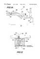
- FIG. 2Ais an isometric view of a portion of the system shown in FIG. 1, namely, a portion of blood receiving means and monitoring means;
- FIG. 2Bis an isometric view of another portion of the system shown in FIG. 1, namely, an exemplary test station;
- FIG. 3is an illustration of the construction and function of the blood receiving means
- FIG. 4is a graph of a parameter measured by the system if FIG. 1, namely, the “head” of the column of fluid plotted versus time;
- FIGS. 5A-5Gare illustrations of a portion of the system shown in FIG. 1 showing the operational sequence thereof;
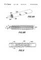
- FIG. 6is an enlarged isometric view of a portion of the system, namely, a capillary tube;
- FIG. 7is a view similar to FIG. 6, but showing an alternative embodiment of the capillary tube
- FIG. 8Ais a view similar to FIG. 6 and 7, but showing an alternative embodiment of the capillary tube
- FIG. 8Bis a greatly enlarged cross-sectional view taken along line 8 B— 8 B of FIG. 8A;
- FIG. 9is an enlarged cross-sectional view of yet another alternative embodiment of the capillary tube.
- FIG. 10is an enlarged sectional view through a portion of the components shown in FIG. 3 to include means, e.g., a buffer piston at the blood/transmission fluid interface to isolate the blood of the being from the transmission fluid used by the system;
- meanse.g., a buffer piston at the blood/transmission fluid interface to isolate the blood of the being from the transmission fluid used by the system;
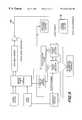
- FIG. 11is a block diagram of a portion of the system shown in FIG. 1, namely, the sensor means;
- FIG. 12is an enlarged cross-sectional view of the sensor means taken along line 12 — 12 of FIG. 2A;
- FIG. 13is an illustration of a calibration test rig for use with the system of FIG. 1;
- FIG. 14is a graph similar to FIG. 4 showing the head of the column of fluid plotted versus time to show a thixotropic characteristic of the blood.
- FIGS. 1A and 1Bthere is shown in FIGS. 1A and 1B at 20 a liquid viscosity measuring system constructed in accordance with the present invention.
- the system 20has particular utility for measuring in-vivo the viscosity of the blood of a living being.
- the apparatus 20has many applications, the preferred embodiment of the apparatus 20 is used to measure the viscosity of the blood anywhere in a patient's vascular system, e.g., veins, arteries, pulmonary system, left atrium, left ventricle, etc.
- vascular systeme.g., veins, arteries, pulmonary system, left atrium, left ventricle, etc.
- bloodis a non-Newtonian fluid.
- a Newtonian fluidmay be defined as one in which the viscosity does not vary with the rate of shear within the non-turbulent flow range, whereas a non-Newtonian fluid, such as blood, exhibits a viscosity that is variable with the rate of shear in the non-turbulent flow range.
- a non-Newtonian fluidsuch as blood
- a curveis produced, instead of a straight line. Therefore, to obtain an accurate determination of blood viscosity, it is necessary to obtain a viscosity measurement over a range of shears.
- the concept of the present inventionis to monitor, on a substantially continuous basis, the rising head of an externally located column of fluid coupled to a portion of the patient's body in which the blood flows, thus, effectively monitoring the patient's blood in-vivo.
- the data from this rising headis used to calculate the viscosity of the blood at a large multiplicity of points during the rise of the column for various different flow rates, thereby providing a viscosity of the blood over a range of shears.
- the monitoring of the rising columnsolves the problem of how to generate a range of shears necessary to obtain an accurate measurement of the blood viscosity.
- the apparatus 20basically comprises a blood sampling means 22 and a calculation means 24 that are coupled together to provide the viscosity measurement.
- the blood sampling means 22comprises a catheter 26 , which in a preferred embodiment comprises a capillary tube.
- the catheter 26has an inside diameter D 1 and a length, L 1 .
- the catheter 26is introduced into the body 28 of the being (patient) to an internal situs 30 (e.g., a vein, artery, etc.) to enable blood 31 to flow into the catheter 26 .
- the catheter 26serves as a blood receiving means.
- the catheter 26is connected via a hub 32 to a conduit means 34 having a inside diameter D 2 .
- a first valve means 36selectively couples an injector means 38 to the conduit means 34 .
- the injector means 38comprises a reservoir 40 for containing an indicator or transmission fluid 41 (e.g., a liquid such as saline solution, alcohol, or any sterile water-type liquid) which, when injected into the conduit means 34 , forms a column of fluid 42 (to be discussed later) that can be monitored (e.g., optically monitored-an optimum dye can be used for coloring the transmission fluid for maximizing readability by an optical sensor).
- the other end of the conduit means 34is coupled to a riser tube 44 .
- the hollow interior of the riser tube 44forms a lumen that permits the column of fluid 42 level to be detected as a function of time.
- the riser tube 44has an inside diameter of D 3 .
- the upper end of the riser tube 44comprises a second valve means 46 (e.g., a 2-way valve) that vents the riser tube 44 to atmosphere when the valve 46 is opened.
- the first valve means 36 and second valve means 46preferably include hydrophobic vents (not shown) to eliminate blood spillage.
- the column of fluid 42is monitored by monitoring means 48 .
- the monitoring means 48comprises a sensor means 50 (e.g., a charge-coupled device, CCD, including associated electronics, FIG. 11 and an associated power supply 51 ) coupled to a microprocessor means 52 (e.g., a personal computer) which further comprises appropriate diagnostic software 54 .
- the monitoring means 48monitors the height of the column of fluid 42 as it rises throughout the length of the riser tube 44 during the test or run to determine the patient's blood viscosity.
- Peripheral indicator means 56e.g., a visual display 58 , a counter means 60 , a printer 62 , provides data and/or graphics pertaining to the viscosity/shear rate measurements.
- a modem 64can be connected to the monitoring means 48 to provide all pertinent data to some remote location, e.g., via the Internet or World Wide Web 66 .
- the visual display 58 and/or printer 62serve to present graphical representations of measured parameters such as viscosity vs. shear, or viscosity vs. height of column of fluid (“head”), or diagnoses.
- the counter means 60is used to numerically display such items as viscosity at a particular shear and/or the head at which the velocity of the column of fluid is zero, e.g., the thixotropic point (to be discussed later).
- the viscosity/shear rate datacan be stored in the microprocessor means 52 and can be compared with databases 54 (on associated CD-ROM, diskette or PC cards) to present possible diagnoses to the physician.
- FIG. 2Adepicts one portion of the implementation of the system 20 .
- the injector means 38 , a portion of the conduit means 34 , the first valve means 36 , the riser 44 , and the second valve means 46are mounted on a support plate 68 to form a tubing assembly 69 .
- the tubing assembly 69is configured to be removably mounted inside a housing 70 which contains the sensor means 50 and the power supply 51 .
- the support plate 68is mounted in the housing 70 with the appropriate connections in order to position the riser tube 44 vertically and directly opposite the sensor means 50 for proper monitoring.
- the appropriate valve control connections 72are made so that the first valve means 36 and second valve means 46 can be properly controlled automatically in sequence.
- the support plate 68comprises a transparent material that permits the sensor means 50 to optically monitor the column of fluid 42 . It should be understood that the injector means 38 is precharged with the transmission fluid 41 which is held captive in the reservoir 40 by the 3-way valve 36 . Only when the valve 36 is properly oriented, does the transmission fluid 41 flow out of the injector means 38 and into the conduit means 34 .
- a door 74can be releasably secured to create a sufficiently dark environment to support proper column illumination 76 and level detection by the sensor means 50 during the run.
- the tubing assembly 69is removed, disconnected from the capillary tube 26 , and then discarded.
- a new tubing assembly 69is connected to the capillary tube 26 and re-installed into the housing 70 .
- first 36 and second valve means 46can be controlled manually, i.e., proper operation of the apparatus 20 does not require automatic control of the first 36 and second valve means 46 .
- FIG. 2 BAn exemplary test station is shown in FIG. 2 B. It should be understood that although the apparatus 20 is shown with the capillary 26 inserted into a patient's arm, the apparatus 20 is not limited in use with that portion of the patient's body. Other station configurations could be used where the capillary 26 is inserted into other portions of the patient's body for blood to flow into the capillary tube 26 . With the test station shown in FIG. 2B, the patient 78 is seated with his/her arm disposed on a horizontal surface 80 . The capillary 26 is inserted percutaneously into the patient's arm until its distal end, and preferably its entire length L 1 , is within a desired vessel, e.g., a vein.
- a desired vessele.g., a vein.
- the conduit means 34couples the capillary 26 to the housing 70 .
- the housing 70is releasably disposed on a fixed vertical surface 82 .
- the vertical surface 82comprises adjustment means 84 that permit the entire housing 70 to be manually displaced in a vertical direction and then releasably secured at any desired vertical height. The important point is that the operator can change the relative vertical position of the housing 70 with respect to the vertical position of the portion of the patient in which the capillary tube 26 has been inserted for reasons to be understood later.
- the microprocessor means 52 , visual display 58 and printer 62are also shown at the station.
- FIG. 3is a functional diagram of the apparatus 20 .
- the basic operation of the apparatus 20is shown in FIG. 3 .
- the sensor means 50e.g., a CCD array
- This optical interfacee.g., meniscus
- Operation of the first valve means 36 and second valve means 46are discussed below.
- D 1is much less than D 2 ;
- D 1is much less than D 3
- ⁇ 1 ⁇ ( t )( ⁇ s ⁇ gtD 1 4 32 ⁇ L 1 ⁇ D 3 2 ) ⁇ 1 ln ⁇ ( h ⁇ h ⁇ - h ⁇ ( t ) ) ⁇ .
- ⁇ 1 (t)represents the viscosity
- ⁇ dot over (y) ⁇ 1 (t)represents the shear rate
- ⁇ srepresents the density of the transmission or indicator fluid
- grepresents the gravitational constant
- tthe time of measurement
- D 1represents the inside diameter of the capillary tube
- L 1represents the length of the capillary tube
- D 3represents the inside diameter of the column of transmission or indicator fluid
- h oorepresents the final height of the column of transmission or indicator fluid
- h(t)represents the instantaneous height of the column of transmission or indicator fluid.
- the viscosity, ⁇ 1 (t), of the bloodis thus graphically represented as shown in FIG. 4 .
- a longer capillary tube 26can be used (i.e., increase L 1 ).
- FIGS. 5A-5HOperation of the apparatus 20 is depicted in FIGS. 5A-5H and is as follows:
- the portion of the patient's vascular system (e.g., vein, artery, etc.) into which the capillary tube 26 is to be insertedis disposed on the horizontal surface 80 .
- This entry point on the patientbecomes the “DATUM” reference and it represents a vertical height reference.
- FIGS. 5 A- 5 BA guidewire 86 is introduced into the vascular system of the patient via a piercer 88 .
- the piercer 88is removed, leaving the guidewire 86 in place.
- the following stepsare preferably automated so that once the capillary tube 26 is inserted in the patient, the operator need only activate a switch (not shown) of a controller (also not shown) that would automatically carry out the following steps:
- FIG. 5 CFirst valve means 36 is opened so that ports A and B are in communication while ports A to C and B to C are closed; the second valve means 46 is closed. The capillary 26 is then flushed.
- FIG. 5 DFirst valve means 36 is totally closed and the capillary 26 is threaded over the guidewire 86 and then disposed into the patients vascular system.
- the DATUM levelis established for the capillary tube 26 and the riser tube 44 .
- a DATUM mark,is made on the fixed vertical surface 82 .
- FIG. 5 EThe guidewire 86 is removed and the DATUM level is established for the capillary tube 26 and the riser tube 44 . A “0” mark is created on the riser tube 44 that is aligned with the DATUM level.
- FIG. 5 FFirst valve means 36 is moved to open communication between ports A and C and second valve means 46 is moved to open communication between ports D and E. The operator then depresses the plunger 90 on the injection means 38 to fill the riser tube 44 with transmission or indicatorfluid up to the “0” or DATUM mark. Both the first valve means 36 and the second valve means 46 are then closed.
- FIG. 5 FPermit blood pressure to pressurize the column of fluid 42 .
- the operatoropens the first valve means 36 so that ports B and C are in communication, thereby permitting blood to flow (approximately 0.5 cc of blood) into conduit means 34 .
- the column of fluid 42will rise from the 0 mark to a new level.
- the operatorthen manually displaces the housing 70 downward until the new level is aligned with the DATUM mark on the fixed vertical surface 82 . This action permits the determination of blood's (e.g., the venous) static pressure using the closed-off riser tube 44 as a “barometer.”
- blood'se.g., the venous
- FIG. 5 GTo avoid overflowing the riser tube 44 during the run, it is necessary to calculate the approximate final level or head, h oo , of the column of fluid 42 and to lower the housing 70 by that amount. Boyle's Law is used to estimate the likely rise h oo of the column of fluid 42 in step 5 F. The housing 70 is then dropped by the amount h oo . The housing 70 is then secured at that height to prepare the sensor means 50 to monitor the rise of the column of fluid 42 . The second valve means 46 is then opened and the column of fluid 42 begins to rise.
- Boyle's Lawis used to estimate the likely rise h oo of the column of fluid 42 in step 5 F.
- the housing 70is then dropped by the amount h oo .
- the housing 70is then secured at that height to prepare the sensor means 50 to monitor the rise of the column of fluid 42 .
- the second valve means 46is then opened and the column of fluid 42 begins to rise.
- the tubing assembly 69is discarded and a new tubing assembly 69 installed in the housing. If the transmission fluid 41 in the injector means 38 is of a biocompatible material, a portion of the transmission fluid 41 can be used to flush the apparatus 20 , all the way to the tip of the capillary tube 26 , as shown in FIG. 5 C.
- a current barometric pressure readingis obtained (e.g., from a barometer not shown, internal to the calculation means 24 ) and is provided to the microprocessor means 52 .
- the apparatus 20calculates the proper viscosity/shear rate plot based on the existing current atmospheric pressure.
- ventsmay be provided throughout the apparatus 20 to minimize the effect on computed viscosity accuracy.
- a hemostasis valvee.g., a “Heparin Lock”
- a hemostasis valvehaving a “Y” fitting could be disposed close to the point where the capillary tube 28 enters the vessel in order to permit the passage of a the guide wire 86 after the apparatus 20 is flushed without getting air bubbles.
- the capillary tube 26should constructed of, or coated with, a material or materials that prevent the blood 31 from adhering to the capillary tube's internal walls, e.g., an anti-thrombogenic material, such as Heparin, and/or ant;-thrombolytic coatings, e.g., phosphoryl choline, etc., can be used to minimize blood clotting.
- an anti-thrombogenic materialsuch as Heparin, and/or ant
- -thrombolytic coatingse.g., phosphoryl choline, etc.
- Phosphoryl choline compoundsare available from Biocompatibles, Ltd., Uxbridge, UK.
- Such a construction or coatingsfacilitate the long-term placement of the capillary tube 26 within the vascular system of the patient.
- the tip of the capillary tube 26preferably comprises a plurality of ports 92 .
- FIG. 7An alternative embodiment of the capillary tube 26 is shown in FIG. 7 and includes an intravascular capillary with a controlled lumen or resistor for the viscometer function and with another for measuring pressure.
- the capillary tube 126comprises a first lumen 96 for transmitting the blood 31 as discussed previously and comprises a second lumen 98 that is coupled to a pressure transducer (not shown) that is coupled to the calculation means 24 .
- the second lumen 98provides a continuous reference of the patients blood pressure to the calculation means 24 .
- the calculation means 24is provided with a continuous blood pressure reference throughout the run.
- the actual blood pressuremay change during the run.
- Such blood pressure variations or pulsationsneed to be accounted for in determining the proper viscosity/shear versus time curve. Having a continuous blood pressure reference can thus be compensated for during the blood viscosity/shear determination.
- FIGS. 8A-8B and 9Another alternative embodiment of the capillary tube 26 is shown in FIGS. 8A-8B and 9 .
- This embodimentincludes an intravascular capillary with a controlled lumen or tube with alternative resistive members, such as a number of small capillary tubes in a bundle (FIGS. 8 A- 8 B).
- the tubeis filled with very small spheres (FIG. 9 ), or a sintered column (not shown).
- the capillary tube 226comprises a plurality of small capillaries 100 , each having different internal diameters (d 1 , d 2 , d 3 , etc.).
- the system 20can be used to determine the blood pressure at which blood flow starts. This action provides an indication of the deformability of the being's red blood cells since those cells will have to deform to pass through the small capillaries 100 .
- the capillary tube 326includes very small spheres 102 within it to create interstices which are smaller than the average diameter of a red blood cell, so that such cells will have to deform to pass therethrough.
- a buffer piston as shown in FIG. 10may be used. That piston can be of any suitable construction, e.g., a carbon slug to isolate the blood 31 from the transmission fluid 41 at their interface.
- the piston 104having a specific gravity of approximately 1.0, transmits the motion or flow of the blood 31 down the capillary tube to the transmission fluid 41 while isolating or separating these two fluids from each other.
- a buffer fluidcould be introduced at the interface between the blood 31 and the transmission fluid 41 to reduce any miscibility/contamination problems.
- FIG. 11is a block diagram of the sensor means 50
- FIG. 12shows its construction, i.e., a cross-sectional view of it taken along line 12 - 12 of FIG. 2A but with the support plate 68 already secured to the housing 70 .
- an exemplary implementation of the sensor means 50comprises a linear array of illuminators 76 (see FIGS. 2 A and 12 ), rod lenses 106 , and sensor chips 108 mounted on a PCB substrate 110 .
- One particularly useful commercial device incorporating their componentsis the Model SV200A4 sold by Scan Vision, Inc. of San Jose, Calif.
- the sensor means 50includes a glass cover 112 that abuts the riser tube 44 when the support 68 is installed, as described earlier.
- An integrated lens 114may be disposed on the opposite side of the glass cover 112 to improve viewing by the rod lens 106 .
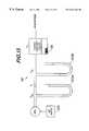
- FIG. 13depicts an exemplary test rig 116 for the tubing assembly 69 of the system 20 .
- a bar code 118is provided on the support plate 68 (FIGS. 2A and 13) that contains a calibration factor for that particular tubing assembly 69 .
- an automatic scanner 119coupled to the PC 52 , scans the bar code 118 and loads the PC 52 with the particular calibration factor.
- the tubing assembly under calibration, A 2is coupled to the test rig 116 , as shown in FIG. 13 .
- An air supply 120delivers clean dry air at a predetermined pressure, P AS (e.g., 100 psi) that can be regulated (via a regulator REG) down to 30in H 2 O.
- P ASe.g., 100 psi
- the air supply 120delivers the flow through a calibrated orifice, A 1 , having a known resistance.
- the input of the tubing assembly under test A 2is coupled to the output of A 1 and the output of the tubing assembly under test A 2 is vented to atmosphere.
- a pressure, P TAappears at the input of the tubing assembly under test, A 2 .
- a pair of open-ended manometers 122A and 122Bare coupled to the input of A 1 and the output of A 1 , respectively, to monitor P AS and P TA , respectively.
- the ratio P AS /P TArepresents the calibration factor.
- This calibration factoris then encoded into the bar code 118 .
- the system 20includes the means for controlling the formation of a meniscus 124 (FIG. 3) at the top of the column of transmission fluid 42 .
- coatings for the riser tube 44can be introduced to control the surface tension precisely by providing controlled surface energy, thus flattening the meniscus 124 .
- This meniscus 124can be further controlled by changing the molecular make-up of the riser tube 44 , the transmission fluid 41 being used and the gas above the column of fluid 42 .
- the inner surfaces of riser tube 44maybe coated by vapor deposition with surfactants, e.g., silicone. By including suitable surfactants, such as silicone, in the extrusions the surfactants migrate to the surfaces in a predictable manner.
- Another embodiment (not shown) of the apparatus 20includes a riser tube 44 that is inclined to increase the sensitivity.
- the riser tube 44were angled away from a vertical orientation, for each millimeter rise in vertical height of the column of fluid 42 , there will be more than one millimeter of displacement of the column of fluid 42 in the riser tube 44 .
- means 124can be provided to apply vibratory energy to the patient to determine its effect on the patient's blood viscosity and the data developed can then be used to provide customized vibratory therapy to provide beneficial effects.
- a vibration source 124that generates vibratory energy whose amplitude and frequency can be controlled by the operator. This vibratory energy is applied either before or during a viscosity measuring run.
- the vibratory energyis shown in FIG. 2B as being applied to the patient's arm only, it is within the broadest scope of the invention that the vibratory energy can be applied to all or only a portion of the patient's body.
- the vibrationmay also be applied to the column of fluid 42 , and/or to the capillary tube 26 , to obtain a smoother flow of fluid.
- Another significant feature of the system 20is its ability to monitor the level of the column of fluid 42 at which the velocity becomes zero, i.e., the thixotropic point of the blood flow.
- the thixotropic pointrepresents a shear stress being supported at zero velocity, as graphically depicted in FIG. 14 .
- Presentation of the shear or head at which flow restarts after a set time at zero motionprovides an indication of the clotting characteristic of the patient.
- the diagnostic software 54allows for the dynamic effects of deceleration of the column of fluid 42 and for the viscous effects of the various diameters of tubing as the blood 31 and the transmission fluid 41 pass through the system 20 .
- system 20comprises a molded or etched channel system as a substitute for the tubing discussed above.
- the apparatus 20has other applications, such as viscosity measurements of other flowable material, e.g., oils, paints and cosmetics.
- other flowable materiale.g., oils, paints and cosmetics.
Landscapes
- Health & Medical Sciences (AREA)
- Life Sciences & Earth Sciences (AREA)
- Engineering & Computer Science (AREA)
- General Health & Medical Sciences (AREA)
- Physics & Mathematics (AREA)
- Pathology (AREA)
- Animal Behavior & Ethology (AREA)
- Biomedical Technology (AREA)
- Heart & Thoracic Surgery (AREA)
- Medical Informatics (AREA)
- Molecular Biology (AREA)
- Surgery (AREA)
- Biophysics (AREA)
- Public Health (AREA)
- Veterinary Medicine (AREA)
- Hematology (AREA)
- Immunology (AREA)
- Chemical & Material Sciences (AREA)
- Analytical Chemistry (AREA)
- Biochemistry (AREA)
- General Physics & Mathematics (AREA)
- Cardiology (AREA)
- Manufacturing & Machinery (AREA)
- Physiology (AREA)
- Investigating Or Analysing Biological Materials (AREA)
- Measurement Of The Respiration, Hearing Ability, Form, And Blood Characteristics Of Living Organisms (AREA)
- Measuring Pulse, Heart Rate, Blood Pressure Or Blood Flow (AREA)
Abstract
Description

Claims (19)
Priority Applications (4)
| Application Number | Priority Date | Filing Date | Title |
|---|---|---|---|
| US09/383,177US6261244B1 (en) | 1997-08-28 | 1999-08-25 | Viscosity measuring apparatus and method of use |
| US09/631,046US6659965B1 (en) | 1997-08-28 | 2000-08-01 | Viscosity measuring apparatus and method of use |
| US09/836,103US20010022654A1 (en) | 1997-08-28 | 2001-04-17 | Method & apparatus for determining red blood cell deformability by imaging red blood cells while applying vibratory energy |
| US10/184,548US6805674B2 (en) | 1997-08-28 | 2002-06-28 | Viscosity measuring apparatus and method of use |
Applications Claiming Priority (3)
| Application Number | Priority Date | Filing Date | Title |
|---|---|---|---|
| US08/919,906US6019735A (en) | 1997-08-28 | 1997-08-28 | Viscosity measuring apparatus and method of use |
| US09/103,232US6077234A (en) | 1997-08-28 | 1998-06-23 | In-vivo apparatus and method of use for determining the effects of materials, conditions, activities, and lifestyles on blood parameters |
| US09/383,177US6261244B1 (en) | 1997-08-28 | 1999-08-25 | Viscosity measuring apparatus and method of use |
Related Parent Applications (1)
| Application Number | Title | Priority Date | Filing Date |
|---|---|---|---|
| US08/919,906ContinuationUS6019735A (en) | 1997-08-28 | 1997-08-28 | Viscosity measuring apparatus and method of use |
Related Child Applications (1)
| Application Number | Title | Priority Date | Filing Date |
|---|---|---|---|
| US09/631,046ContinuationUS6659965B1 (en) | 1997-08-28 | 2000-08-01 | Viscosity measuring apparatus and method of use |
Publications (1)
| Publication Number | Publication Date |
|---|---|
| US6261244B1true US6261244B1 (en) | 2001-07-17 |
Family
ID=52016276
Family Applications (9)
| Application Number | Title | Priority Date | Filing Date |
|---|---|---|---|
| US08/919,906Expired - Fee RelatedUS6019735A (en) | 1997-08-28 | 1997-08-28 | Viscosity measuring apparatus and method of use |
| US09/103,232Expired - LifetimeUS6077234A (en) | 1997-08-28 | 1998-06-23 | In-vivo apparatus and method of use for determining the effects of materials, conditions, activities, and lifestyles on blood parameters |
| US09/383,177Expired - LifetimeUS6261244B1 (en) | 1997-08-28 | 1999-08-25 | Viscosity measuring apparatus and method of use |
| US09/400,501Expired - LifetimeUS6152888A (en) | 1997-08-28 | 1999-09-21 | Viscosity measuring apparatus and method of use |
| US09/441,226Expired - LifetimeUS6200277B1 (en) | 1997-08-28 | 1999-11-15 | In-vivo apparatus and methods of use for determining the effects of materials, conditions, activities, and lifestyles on blood parameters |
| US09/440,429Expired - LifetimeUS6193667B1 (en) | 1997-08-28 | 1999-11-15 | Methods of determining the effect(s) of materials, conditions, activities and lifestyles |
| US09/629,216Expired - Fee RelatedUS6443911B1 (en) | 1997-08-28 | 2000-07-31 | Viscosity measuring apparatus and method of use |
| US09/631,046Expired - LifetimeUS6659965B1 (en) | 1997-08-28 | 2000-08-01 | Viscosity measuring apparatus and method of use |
| US10/184,548Expired - LifetimeUS6805674B2 (en) | 1997-08-28 | 2002-06-28 | Viscosity measuring apparatus and method of use |
Family Applications Before (2)
| Application Number | Title | Priority Date | Filing Date |
|---|---|---|---|
| US08/919,906Expired - Fee RelatedUS6019735A (en) | 1997-08-28 | 1997-08-28 | Viscosity measuring apparatus and method of use |
| US09/103,232Expired - LifetimeUS6077234A (en) | 1997-08-28 | 1998-06-23 | In-vivo apparatus and method of use for determining the effects of materials, conditions, activities, and lifestyles on blood parameters |
Family Applications After (6)
| Application Number | Title | Priority Date | Filing Date |
|---|---|---|---|
| US09/400,501Expired - LifetimeUS6152888A (en) | 1997-08-28 | 1999-09-21 | Viscosity measuring apparatus and method of use |
| US09/441,226Expired - LifetimeUS6200277B1 (en) | 1997-08-28 | 1999-11-15 | In-vivo apparatus and methods of use for determining the effects of materials, conditions, activities, and lifestyles on blood parameters |
| US09/440,429Expired - LifetimeUS6193667B1 (en) | 1997-08-28 | 1999-11-15 | Methods of determining the effect(s) of materials, conditions, activities and lifestyles |
| US09/629,216Expired - Fee RelatedUS6443911B1 (en) | 1997-08-28 | 2000-07-31 | Viscosity measuring apparatus and method of use |
| US09/631,046Expired - LifetimeUS6659965B1 (en) | 1997-08-28 | 2000-08-01 | Viscosity measuring apparatus and method of use |
| US10/184,548Expired - LifetimeUS6805674B2 (en) | 1997-08-28 | 2002-06-28 | Viscosity measuring apparatus and method of use |
Country Status (12)
| Country | Link |
|---|---|
| US (9) | US6019735A (en) |
| EP (2) | EP1007941A2 (en) |
| JP (2) | JP2001514384A (en) |
| CN (2) | CN1273634A (en) |
| AU (2) | AU737207B2 (en) |
| BR (1) | BR9814446A (en) |
| CA (2) | CA2301161A1 (en) |
| HU (2) | HUP0100201A3 (en) |
| IL (2) | IL134752A0 (en) |
| NO (2) | NO20000944L (en) |
| NZ (1) | NZ502905A (en) |
| WO (2) | WO1999010724A2 (en) |
Cited By (26)
| Publication number | Priority date | Publication date | Assignee | Title |
|---|---|---|---|---|
| US20020040196A1 (en)* | 1997-08-28 | 2002-04-04 | Kenneth Kensey | Dual riser/single capillary viscometer |
| US20020067106A1 (en)* | 2000-12-05 | 2002-06-06 | Samsung Electro-Mechanics Co., Ltd. | Film bulk acoustic resonator and method for fabrication thereof |
| US6412336B2 (en) | 2000-03-29 | 2002-07-02 | Rheologics, Inc. | Single riser/single capillary blood viscometer using mass detection or column height detection |
| US6477891B2 (en)* | 1997-04-07 | 2002-11-12 | Disetronic Licensing, Ag | Process for affinity viscosimetry and viscosimetric affinity sensor |
| US20020169370A1 (en)* | 1997-08-28 | 2002-11-14 | Rheologics, Inc. | Viscosity measuring apparatus and method of use |
| US20030032869A1 (en)* | 2001-07-09 | 2003-02-13 | Hiroyuki Muramatsu | Blood rheology measuring apparatus |
| US6564618B2 (en) | 2000-05-18 | 2003-05-20 | Rheologics, Inc. | Electrorheological and magnetorheological fluid scanning rheometer |
| US6571608B2 (en) | 1999-11-12 | 2003-06-03 | Rheologics, Inc. | Single riser/single capillary viscometer using mass detection or column height detection |
| US20030158500A1 (en)* | 1999-11-12 | 2003-08-21 | Kenneth Kensey | Decreasing pressure differential viscometer |
| US6624435B2 (en) | 1997-08-28 | 2003-09-23 | Rheologics, Inc. | Dual riser/dual capillary viscometer for newtonian and non-newtonian fluids |
| US6692437B2 (en) | 1999-11-12 | 2004-02-17 | Rheologics, Inc. | Method for determining the viscosity of an adulterated blood sample over plural shear rates |
| US6706000B2 (en) | 1997-11-21 | 2004-03-16 | Amira Medical | Methods and apparatus for expressing body fluid from an incision |
| US6715915B1 (en)* | 1999-08-13 | 2004-04-06 | Morinaga Milk Industry Co., Ltd. | Fluidity determination method of a packed fluid and device used in the same |
| US20040133127A1 (en)* | 2002-12-30 | 2004-07-08 | Roe Jeffrey N. | Capillary tube tip design to assist blood flow |
| US6840092B2 (en)* | 2000-01-31 | 2005-01-11 | Borealis Technology Oy | Method and apparatus for rheometry, and its application to control of polymer manufacture |
| US20050214131A1 (en)* | 2002-08-21 | 2005-09-29 | Medquest Products, Inc. | Methods and systems for determining a viscosity of a fluid |
| US20070116699A1 (en)* | 2005-06-24 | 2007-05-24 | N-Zymeceuticals, Inc. | Nattokinase for reducing whole blood viscosity |
| US20090205410A1 (en)* | 2008-02-14 | 2009-08-20 | Meng-Yu Lin | Apparatus for measuring surface tension |
| US20090240123A1 (en)* | 2008-03-18 | 2009-09-24 | Wayne Siebrecht | Determining relative blood hematocrit level using an automated integrated fluid delivery and blood access device |
| US7727168B2 (en) | 1996-05-17 | 2010-06-01 | Roche Diagnostics Operations, Inc. | Methods and apparatus for sampling and analyzing body fluid |
| US7758518B2 (en) | 2001-06-08 | 2010-07-20 | Roche Diagnostics Operations, Inc. | Devices and methods for expression of bodily fluids from an incision |
| US7828749B2 (en) | 1996-05-17 | 2010-11-09 | Roche Diagnostics Operations, Inc. | Blood and interstitial fluid sampling device |
| US7841991B2 (en) | 1996-05-17 | 2010-11-30 | Roche Diagnostics Operations, Inc. | Methods and apparatus for expressing body fluid from an incision |
| US7901363B2 (en) | 1996-05-17 | 2011-03-08 | Roche Diagnostics Operations, Inc. | Body fluid sampling device and methods of use |
| CN102177379A (en)* | 2008-10-08 | 2011-09-07 | 弗洛申公司 | A method of forming a flow restriction in a fluid communication system |
| US10545079B2 (en)* | 2015-11-24 | 2020-01-28 | Industrial Cooperation Foundation Chonbuk National University | Portable blood viscosity measurement apparatus |
Families Citing this family (72)
| Publication number | Priority date | Publication date | Assignee | Title |
|---|---|---|---|---|
| US6450974B1 (en) | 1997-08-28 | 2002-09-17 | Rheologics, Inc. | Method of isolating surface tension and yield stress in viscosity measurements |
| US6322524B1 (en) | 1997-08-28 | 2001-11-27 | Visco Technologies, Inc. | Dual riser/single capillary viscometer |
| US6322525B1 (en) | 1997-08-28 | 2001-11-27 | Visco Technologies, Inc. | Method of analyzing data from a circulating blood viscometer for determining absolute and effective blood viscosity |
| US6296615B1 (en)* | 1999-03-05 | 2001-10-02 | Data Sciences International, Inc. | Catheter with physiological sensor |
| US7220438B2 (en)* | 1999-09-23 | 2007-05-22 | Asac Compañia de Biotecnologia | Pharmacological activities of Curcuma longa extracts |
| ES2154610B1 (en)* | 1999-09-23 | 2001-11-16 | Asac Compania De Biotecnologia | NEW PHARMACOLOGICAL ACTIVITIES OF CURCUMA LONGA EXTRACTS. |
| AU2004200837B2 (en)* | 1999-11-12 | 2007-05-17 | Rheologics, Inc. | Dual riser/single capillary viscometer |
| US6912576B1 (en)* | 2000-05-04 | 2005-06-28 | Broadcom Corporation | System and method of processing data flow in multi-channel, multi-service environment by dynamically allocating a socket |
| WO2002009583A2 (en)* | 2000-08-01 | 2002-02-07 | Rheologics, Inc. | Apparatus and methods for comprehensive blood analysis, including work of, and contractility of, heart and therapeutic applications and compositions thereof |
| AU2002226986A1 (en)* | 2000-12-01 | 2002-06-11 | Rheologics, Inc. | In vivo delivery methods and compositions |
| WO2002079778A2 (en)* | 2001-03-28 | 2002-10-10 | Rheologics, Inc. | In vivo delivery methods and compositions |
| WO2003029785A1 (en)* | 2001-09-28 | 2003-04-10 | Rheologics, Inc. | Inline blood viscometer for continually monitoring the circulating blood of a living being |
| US8101209B2 (en)* | 2001-10-09 | 2012-01-24 | Flamel Technologies | Microparticulate oral galenical form for the delayed and controlled release of pharmaceutical active principles |
| TW570769B (en)* | 2002-04-26 | 2004-01-11 | Chin-Yu Lin | Method and device for measuring pulse signals for simultaneously obtaining pulse pressure and blood flow rate |
| AU2003241389A1 (en)* | 2002-05-09 | 2003-11-11 | Biomed Personal Metabolic And Nutritional Testing, Inc. | System and method to test nutritional supplements |
| US7687926B2 (en)* | 2002-06-06 | 2010-03-30 | Black & Decker Inc. | Starter system for portable internal combustion engine electric generators using a portable universal battery pack |
| US7309928B2 (en)* | 2002-06-06 | 2007-12-18 | Black & Decker Inc. | Starter system for portable internal combustion engine electric generators using a portable universal battery pack |
| US7989969B2 (en) | 2002-06-06 | 2011-08-02 | Black & Decker Inc. | Universal power tool battery pack coupled to a portable internal combustion engine |
| US8319357B2 (en)* | 2002-06-06 | 2012-11-27 | Black & Decker Inc. | Starter system for portable internal combustion engine electric generators using a portable universal battery pack |
| US7488309B2 (en)* | 2002-07-03 | 2009-02-10 | Bioanalytical Systems, Inc. | Device and method for drug delivery to animals |
| US7092752B2 (en)* | 2002-07-27 | 2006-08-15 | Sheng-Xing Ma | Skin acupoint/meridian nitric oxide collection kit and method thereof |
| US8003725B2 (en) | 2002-08-12 | 2011-08-23 | Exxonmobil Chemical Patents Inc. | Plasticized hetero-phase polyolefin blends |
| US7271209B2 (en) | 2002-08-12 | 2007-09-18 | Exxonmobil Chemical Patents Inc. | Fibers and nonwovens from plasticized polyolefin compositions |
| US7531594B2 (en) | 2002-08-12 | 2009-05-12 | Exxonmobil Chemical Patents Inc. | Articles from plasticized polyolefin compositions |
| US7998579B2 (en) | 2002-08-12 | 2011-08-16 | Exxonmobil Chemical Patents Inc. | Polypropylene based fibers and nonwovens |
| US7223822B2 (en) | 2002-10-15 | 2007-05-29 | Exxonmobil Chemical Patents Inc. | Multiple catalyst and reactor system for olefin polymerization and polymers produced therefrom |
| US7700707B2 (en)* | 2002-10-15 | 2010-04-20 | Exxonmobil Chemical Patents Inc. | Polyolefin adhesive compositions and articles made therefrom |
| AU2003304716A1 (en) | 2002-10-15 | 2005-11-25 | Exxonmobil Chemical Patents Inc. | Polyolefin adhesive compositions and articles made therefrom |
| FR2847799B1 (en)* | 2002-11-28 | 2005-02-25 | Maxime Formichi | DEVICE FOR ENDOVASCULAR SURGERY |
| WO2004058067A1 (en)* | 2002-12-18 | 2004-07-15 | Lydall, Inc. | Closed system blood sampling device |
| TWI323660B (en)* | 2003-02-25 | 2010-04-21 | Otsuka Pharma Co Ltd | Pten inhibitor or maxi-k channels opener |
| US6952950B2 (en) | 2003-03-07 | 2005-10-11 | Waters Investment Limited | System and method for automatic identification of a detachable component of an instrument |
| JP4385049B2 (en)* | 2003-06-23 | 2009-12-16 | セウォン メディテック インコーポレイテッド | Blood cell deformability measuring device |
| US8192813B2 (en) | 2003-08-12 | 2012-06-05 | Exxonmobil Chemical Patents, Inc. | Crosslinked polyethylene articles and processes to produce same |
| KR101149880B1 (en)* | 2003-08-13 | 2012-05-24 | 루미넥스 코포레이션 | Methods for controlling one or more parameters of a flow cytometer type measurement system |
| US20050113739A1 (en)* | 2003-11-21 | 2005-05-26 | Matthias Stiene | Device and method for extracting body fluid |
| WO2005051325A2 (en)* | 2003-11-25 | 2005-06-09 | Sb Pharmco Puerto Rico Inc. | Carvedilol compositions methods of treatment and delivery |
| ES2662903T3 (en)* | 2003-11-25 | 2018-04-10 | Smithkline Beecham (Cork) Limited | Carvedilol-free base, salts, anhydrous or solvate forms thereof, corresponding pharmaceutical compositions, controlled release formulations, and treatment or administration procedures |
| JP4606727B2 (en)* | 2003-11-28 | 2011-01-05 | 株式会社アドバンス | Body fluid component diagnostic chip |
| US7645829B2 (en)* | 2004-04-15 | 2010-01-12 | Exxonmobil Chemical Patents Inc. | Plasticized functionalized propylene copolymer adhesive composition |
| FR2879290B1 (en)* | 2004-12-10 | 2007-02-02 | Rhodia Chimie Sa | METHOD AND INSTALLATION FOR DETERMINING RHEOLOGICAL CHARACTERISTICS OF A FLUID, AND METHOD OF IDENTIFYING SAME |
| US8389615B2 (en) | 2004-12-17 | 2013-03-05 | Exxonmobil Chemical Patents Inc. | Elastomeric compositions comprising vinylaromatic block copolymer, polypropylene, plastomer, and low molecular weight polyolefin |
| US7812085B2 (en)* | 2005-06-24 | 2010-10-12 | Exxonmobil Chemical Patents Inc. | Functionalized propylene copolymer adhesive composition |
| CN101218296B (en) | 2005-07-15 | 2010-12-08 | 埃克森美孚化学专利公司 | Elastomer composition |
| CA2548931A1 (en)* | 2006-05-11 | 2007-11-11 | The Fluid Life Corporation | Method and apparatus for improving accuracy of optic sensors used in capillary tube instruments |
| US7730769B1 (en) | 2006-05-24 | 2010-06-08 | Kwon Kyung C | Capillary viscometers for use with Newtonian and non-Newtonian fluids |
| US10188826B2 (en)* | 2006-09-29 | 2019-01-29 | Covidien Lp | Catheters including antimicrobial sleeve and methods of making catheters |
| US7782626B2 (en) | 2007-02-02 | 2010-08-24 | Black & Decker Inc. | Portable power driven system with battery anti-theft apparatus |
| CN101959491A (en)* | 2007-03-07 | 2011-01-26 | 盖尔医学生物科技有限公司 | Be used to shorten equipment, the system and method for menstrual phase persistent period |
| DK2157973T3 (en)* | 2007-05-22 | 2015-08-17 | Univ Juntendo | DRUG COMPREHENSIVE A carbostyril derivative donepezil AND TREATMENT Alzheimer's disease |
| EP2128613A1 (en)* | 2008-05-28 | 2009-12-02 | Institut Pasteur | Method for screening compounds for their ability to increase rigidity of red blood cells infected by a protozoan parasite of the genus plasmodium and application thereof |
| US8753290B2 (en)* | 2009-03-27 | 2014-06-17 | Intellectual Inspiration, Llc | Fluid transfer system and method |
| CN102834722B (en)* | 2010-03-30 | 2016-09-07 | Ca卡西索股份公司 | For measuring the compositions of the coagulating property of test liquid |
| FR2959564B1 (en) | 2010-04-28 | 2012-06-08 | Commissariat Energie Atomique | DEVICE FORMING A PRESSURE GAUGE FOR THE DIPHASIC FLUID PRESSURE MEASUREMENT, METHOD OF MAKING THE SAME, AND ASSOCIATED FLUID NETWORK |
| RU2441235C1 (en)* | 2010-06-17 | 2012-01-27 | Государственное образовательное учреждение высшего профессионального образования "Ярославский государственный педагогический университет" им. К.Д. Ушинского (ЯГПУ) | Method for assessing blood cell deformability and device for implementation thereof |
| EP2695581B1 (en)* | 2012-08-07 | 2019-03-13 | Critical Innovations, LLC | Device for simultaneously documenting and treating tension pneumothorax and/or hemothorax |
| CN104619241A (en)* | 2012-08-30 | 2015-05-13 | 西门子公司 | Device and method for in vivo determination of at least one blood value within an object to be examined |
| US9410877B2 (en)* | 2012-10-12 | 2016-08-09 | Halliburton Energy Services, Inc. | Determining wellbore fluid properties |
| RU2522931C1 (en)* | 2012-12-29 | 2014-07-20 | Федеральное Государственное Бюджетное Образовательное Учреждение Высшего Профессионального Образования "Нижегородский Государственный Университет Им. Н.И. Лобачевского" | Method for measuring blood viscosity in vein puncture |
| US20140232853A1 (en) | 2013-02-21 | 2014-08-21 | Neil E. Lewis | Imaging microviscometer |
| WO2014128478A2 (en)* | 2013-02-21 | 2014-08-28 | Malvern Instruments Limited | Imaging microviscometer |
| US10046147B2 (en) | 2013-12-26 | 2018-08-14 | Critical Innovations, LLC | Percutaneous access pathway system and method |
| IN2014MU00233A (en)* | 2014-01-22 | 2015-09-11 | Shivani Scient Ind Private Ltd | |
| JP6393768B2 (en) | 2014-02-25 | 2018-09-19 | セント・ジュード・メディカル,カーディオロジー・ディヴィジョン,インコーポレイテッド | System and method for local electrophysiological representation of cardiac matrix characteristics using a multi-electrode catheter |
| JP6833703B2 (en)* | 2014-11-14 | 2021-02-24 | コラ ヘルスケア インコーポレイテッド | Stroke subtype determination device and method |
| JP6692077B2 (en)* | 2016-01-27 | 2020-05-13 | 国立大学法人九州工業大学 | Body fluid viscosity measurement device |
| EP3603696B1 (en)* | 2017-03-31 | 2022-09-28 | Asahi Kasei Medical Co., Ltd. | Blood purification device, control method thereof, and blood removal defect elimination method |
| CN107389507A (en)* | 2017-06-05 | 2017-11-24 | 河北晨阳工贸集团有限公司 | A kind of true mineral varnish viscosity determining procedure |
| US10814119B2 (en) | 2017-09-22 | 2020-10-27 | Critical Innovations, LLC | Percutaneous access pathway system |
| US11435274B2 (en)* | 2020-06-04 | 2022-09-06 | Saudi Arabian Oil Company | Continuous mud rheology monitoring |
| CN113686735B (en)* | 2021-09-16 | 2023-11-07 | 北京信息科技大学 | Methods and devices for measuring blood coagulation properties |
| CN117179714B (en)* | 2023-08-29 | 2025-05-06 | 中国科学院精密测量科学与技术创新研究院 | A magnetic resonance method for online measurement and drawing of viscosity-shear rate curves |
Citations (75)
| Publication number | Priority date | Publication date | Assignee | Title |
|---|---|---|---|---|
| US1810992A (en) | 1926-01-07 | 1931-06-23 | Dallwitz-Wegner Richard Von | Method and means for determining the viscosity of liquid substances |
| US2343061A (en) | 1943-10-29 | 1944-02-29 | Irany Ernest Paul | Capillary viscometer |
| US2696734A (en) | 1950-05-03 | 1954-12-14 | Standard Oil Co | Viscometer for semifluid substances |
| US2700891A (en) | 1953-12-01 | 1955-02-01 | Montgomery R Shafer | Direct reading viscometer |
| US2934944A (en) | 1955-02-14 | 1960-05-03 | Gerber Prod | Continuous viscosimeter |
| US3071961A (en) | 1959-12-22 | 1963-01-08 | Exxon Research Engineering Co | Automatic viscometer and process of using same |
| US3116630A (en) | 1960-07-21 | 1964-01-07 | Sinclair Research Inc | Continuous viscosimeter |
| US3137161A (en) | 1959-10-01 | 1964-06-16 | Standard Oil Co | Kinematic viscosimeter |
| US3138950A (en) | 1961-03-20 | 1964-06-30 | Phillips Petroleum Co | Apparatus for concurrent measurement of polymer melt viscosities at high and low shear rates |
| US3277694A (en) | 1965-08-20 | 1966-10-11 | Cannon Instr Company | Viscometer |
| US3286511A (en) | 1963-01-17 | 1966-11-22 | Coulter Electronics | Viscosity measurement |
| US3342063A (en) | 1965-02-23 | 1967-09-19 | Technicon Instr | Blood-viscosity measuring apparatus |
| US3435665A (en) | 1966-05-20 | 1969-04-01 | Dow Chemical Co | Capillary viscometer |
| US3520179A (en) | 1968-06-19 | 1970-07-14 | John C Reed | Variable head rheometer for measuring non-newtonian fluids |
| US3604247A (en) | 1968-07-19 | 1971-09-14 | Anvar | Automatic viscosity meter |
| US3666999A (en) | 1970-06-22 | 1972-05-30 | Texaco Inc | Apparatus for providing signals corresponding to the viscosity of a liquid |
| US3680362A (en) | 1970-03-17 | 1972-08-01 | Kunstharsfabriek Synthese Nv | Viscosimeter |
| US3699804A (en) | 1970-01-22 | 1972-10-24 | Ciba Geigy Ag | Capillary viscometer |
| US3713328A (en) | 1971-02-24 | 1973-01-30 | Idemitsu Kosan Co | Automatic measurement of viscosity |
| US3720097A (en) | 1971-01-21 | 1973-03-13 | Univ Pennsylvania | Apparatus and method for measuring mammalian blood viscosity |
| US3782173A (en) | 1971-06-03 | 1974-01-01 | Akzo Nv | Viscosimeter |
| US3839901A (en) | 1972-11-17 | 1974-10-08 | E Finkle | Method and apparatus for measuring viscosity |
| US3853121A (en) | 1973-03-07 | 1974-12-10 | B Mizrachy | Methods for reducing the risk of incurring venous thrombosis |
| US3864962A (en) | 1972-04-10 | 1975-02-11 | Ciba Geigy Ag | Capillary viscosimeter |
| US3908441A (en) | 1972-06-02 | 1975-09-30 | Instr De Controle Et D Analyse | Level detecting device |
| US3911728A (en) | 1973-02-19 | 1975-10-14 | Daillet S A Ets | Coagulation detection apparatus |
| US3952577A (en) | 1974-03-22 | 1976-04-27 | Canadian Patents And Development Limited | Apparatus for measuring the flow rate and/or viscous characteristics of fluids |
| US3967934A (en) | 1969-06-13 | 1976-07-06 | Baxter Laboratories, Inc. | Prothrombin timer |
| US3990295A (en) | 1974-09-16 | 1976-11-09 | Boehringer Ingelheim Gmbh | Apparatus and method for the performance of capillary viscosimetric measurements on non-homogeneous liquids |
| US3999538A (en) | 1975-05-22 | 1976-12-28 | Buren Philpot V Jun | Method of blood viscosity determination |
| US4149405A (en) | 1977-01-10 | 1979-04-17 | Battelle, Centre De Recherche De Geneve | Process for measuring the viscosity of a fluid substance |
| US4165632A (en) | 1976-03-27 | 1979-08-28 | Torsten Kreisel | Method of measuring the fluidity of liquids for medical and pharmaceutical purposes, and apparatus for performing the method |
| US4193293A (en) | 1977-04-28 | 1980-03-18 | E.L.V.I. S.P.A. | Apparatus for determining blood elasticity parameters |
| US4207870A (en) | 1978-06-15 | 1980-06-17 | Becton, Dickinson And Company | Blood sampling assembly having porous vent means vein entry indicator |
| US4302965A (en) | 1979-06-29 | 1981-12-01 | Phillips Petroleum Company | Viscometer |
| US4341111A (en) | 1979-03-05 | 1982-07-27 | Fresenius Ag | Process and apparatus for determining the visco elastic characteristics of fluids |
| US4417584A (en) | 1981-05-25 | 1983-11-29 | Institut National De La Sante Et De La Recherche Medicale | Real-time measuring method and apparatus displaying flow velocities in a segment of vessel |
| US4426878A (en) | 1981-10-13 | 1984-01-24 | Core Laboratories, Inc. | Viscosimeter |
| US4432761A (en) | 1981-06-22 | 1984-02-21 | Abbott Laboratories | Volumetric drop detector |
| US4517830A (en) | 1982-12-20 | 1985-05-21 | Gunn Damon M | Blood viscosity instrument |
| US4519239A (en) | 1982-05-13 | 1985-05-28 | Holger Kiesewetter | Apparatus for determining the flow shear stress of suspensions in particular blood |
| US4554821A (en) | 1982-08-13 | 1985-11-26 | Holger Kiesewetter | Apparatus for determining the viscosity of fluids, in particular blood plasma |
| USH93H (en) | 1985-09-23 | 1986-07-01 | The United States Of America As Represented By The Secretary Of The Army | Elongational rheometer |
| US4616503A (en) | 1985-03-22 | 1986-10-14 | Analysts, Inc. | Timer trigger for capillary tube viscometer and method of measuring oil properties |
| US4637250A (en) | 1985-01-25 | 1987-01-20 | State University Of New York | Apparatus and method for viscosity measurements for Newtonian and non-Newtonian fluids |
| US4643021A (en) | 1984-10-30 | 1987-02-17 | Bertin & Cie | Method and apparatus for measuring the rheological characteristics of a fluid, in particular of a biological fluid such as blood |
| US4680958A (en) | 1985-07-18 | 1987-07-21 | Solvay & Cie | Apparatus for fast determination of the rheological properties of thermoplastics |
| US4680957A (en) | 1985-05-02 | 1987-07-21 | The Davey Company | Non-invasive, in-line consistency measurement of a non-newtonian fluid |
| US4750351A (en) | 1987-08-07 | 1988-06-14 | The United States Of America As Represented By The Secretary Of The Army | In-line viscometer |
| US4858127A (en) | 1986-05-30 | 1989-08-15 | Kdl Technologies, Inc. | Apparatus and method for measuring native mammalian blood viscosity |
| US4856322A (en) | 1988-02-17 | 1989-08-15 | Willett International Limited | Method and device for measuring the viscosity of an ink |
| US4884577A (en) | 1984-10-31 | 1989-12-05 | Merrill Edward Wilson | Process and apparatus for measuring blood viscosity directly and rapidly |
| US4899575A (en) | 1988-07-29 | 1990-02-13 | Research Foundation Of State University Of New York | Method and apparatus for determining viscosity |
| US4947678A (en) | 1988-03-07 | 1990-08-14 | Snow Brand Milk Products Co., Ltd. | Method for measurement of viscosity change in blood or the like and sensor thereof |
| US5099698A (en) | 1989-04-14 | 1992-03-31 | Merck & Co. | Electronic readout for a rotameter flow gauge |
| US5142899A (en) | 1989-11-27 | 1992-09-01 | Skc Limited | Automatic viscosity measuring device |
| US5181415A (en) | 1990-07-20 | 1993-01-26 | Serbio | Apparatus for detecting a change of viscosity by measuring a relative slip, in particular for detecting the coagulation rate of blood |
| US5222497A (en) | 1991-01-25 | 1993-06-29 | Nissho Corporation | Hollow needle for use in measurement of viscosity of liquid |
| US5224375A (en) | 1991-05-07 | 1993-07-06 | Skc Limited | Apparatus for automatically measuring the viscosity of a liquid |
| US5257529A (en) | 1990-12-28 | 1993-11-02 | Nissho Corporation | Method and device for measurement of viscosity of liquids |
| US5271398A (en) | 1991-10-09 | 1993-12-21 | Optex Biomedical, Inc. | Intra-vessel measurement of blood parameters |
| US5272912A (en) | 1992-03-30 | 1993-12-28 | Yayoi Co., Ltd. | Apparatus and method for measuring viscosities of liquids |
| US5327778A (en) | 1992-02-10 | 1994-07-12 | Park Noh A | Apparatus and method for viscosity measurements using a controlled needle viscometer |
| US5333497A (en) | 1991-11-05 | 1994-08-02 | Metron As | Method and apparatus for continuous measurement of liquid flow velocity |
| WO1994020832A1 (en) | 1993-03-03 | 1994-09-15 | Vianova Kunstharz Aktiengesellschaft | Process and device for finding the rheological properties of liquids |
| FR2704151A1 (en) | 1993-04-21 | 1994-10-28 | Klotz Antoine Olivier | Electronic device for adrenergic stimulation of the sympathetic system relating to the venous media. |
| US5365776A (en) | 1992-07-06 | 1994-11-22 | Schott Gerate Gmbh | Process and device for determining the viscosity of liquids |
| EP0654238A1 (en) | 1993-11-18 | 1995-05-24 | Creata Promotion (Aust.) Pty. Limited | Utensil holding container |
| US5421328A (en) | 1992-06-29 | 1995-06-06 | Minnesota Mining And Manufacturing Company | Intravascular blood parameter sensing system |
| US5443078A (en) | 1992-09-14 | 1995-08-22 | Interventional Technologies, Inc. | Method for advancing a guide wire |
| US5447440A (en) | 1993-10-28 | 1995-09-05 | I-Stat Corporation | Apparatus for assaying viscosity changes in fluid samples and method of conducting same |
| US5491408A (en) | 1990-07-20 | 1996-02-13 | Serbio | Device for detecting the change of viscosity of a liquid electrolyte by depolarization effect |
| US5494639A (en) | 1993-01-13 | 1996-02-27 | Behringwerke Aktiengesellschaft | Biosensor for measuring changes in viscosity and/or density of a fluid |
| US5549119A (en) | 1994-09-13 | 1996-08-27 | Cordis Corporation | Vibrating tip catheter |
| US5686659A (en) | 1993-08-31 | 1997-11-11 | Boehringer Mannheim Corporation | Fluid dose flow and coagulation sensor for medical instrument |
Family Cites Families (16)
| Publication number | Priority date | Publication date | Assignee | Title |
|---|---|---|---|---|
| DE654286C (en) | 1932-11-30 | 1937-12-16 | Emil Zbinden | Remote switchgear with only one control conductor |
| FR1426824A (en) | 1964-03-26 | 1966-01-28 | Reckitt & Colman Overseas | Perfecting polishing |
| US3712328A (en)* | 1971-08-05 | 1973-01-23 | Scovill Manufacturing Co | Tire valve core |
| US3908411A (en) | 1973-06-06 | 1975-09-30 | Michael E Fahmie | Unitized washing machine bushing |
| DE2510257C2 (en) | 1975-03-08 | 1987-03-12 | Werner 6228 Eltville Deussen | Container closure with screw cap and spray or drip insert |
| DE3138514A1 (en) | 1981-09-28 | 1983-04-14 | Klaus Dipl.-Ing. 5100 Aachen Mussler | Method and device for determining the flow behaviour of biological liquids |
| JPS5911835A (en)* | 1982-07-14 | 1984-01-21 | 松下電器産業株式会社 | ultrasound doppler device |
| US4461830A (en)* | 1983-01-20 | 1984-07-24 | Buren Philpot V Jun | Serum fibrinogen viscosity in clinical medicine |
| AU1570892A (en)* | 1991-03-04 | 1992-10-06 | Kensey Nash Corporation | Apparatus and method for determining deformability of red blood cells of a living being |
| ES2092937B1 (en)* | 1993-06-04 | 1997-06-16 | Electromecanica Bekal S L | ELECTROMECHANICAL EQUIPMENT FOR THE TREATMENT OF VIRAL DISEASES. |
| EP0749570B1 (en)* | 1994-03-07 | 1998-09-16 | Joseph Goodbread | Method and device for measuring the characteristics of an oscillating system |
| DE9420832U1 (en)* | 1994-12-28 | 1996-05-02 | Robert Bosch Gmbh, 70469 Stuttgart | Cross connection for profile bars |
| US5629209A (en)* | 1995-10-19 | 1997-05-13 | Braun, Sr.; Walter J. | Method and apparatus for detecting viscosity changes in fluids |
| US5626209A (en) | 1995-12-26 | 1997-05-06 | Viola; Barry J. | Center pull bicycle brake assembly |
| US5792660A (en)* | 1996-10-02 | 1998-08-11 | University Of Medicine And Dentistry Of New Jersey | Comparative determinants of viscosity in body fluids obtained with probes providing increased sensitivity |
| US6019735A (en)* | 1997-08-28 | 2000-02-01 | Visco Technologies, Inc. | Viscosity measuring apparatus and method of use |
- 1997
- 1997-08-28USUS08/919,906patent/US6019735A/ennot_activeExpired - Fee Related
- 1998
- 1998-06-23USUS09/103,232patent/US6077234A/ennot_activeExpired - Lifetime
- 1998-08-26AUAU92054/98Apatent/AU737207B2/ennot_activeCeased
- 1998-08-26WOPCT/US1998/017657patent/WO1999010724A2/ennot_activeApplication Discontinuation
- 1998-08-26CNCN98809888Apatent/CN1273634A/enactivePending
- 1998-08-26CACA002301161Apatent/CA2301161A1/ennot_activeAbandoned
- 1998-08-26NZNZ502905Apatent/NZ502905A/enunknown
- 1998-08-26JPJP2000507994Apatent/JP2001514384A/enactivePending
- 1998-08-26ILIL13475298Apatent/IL134752A0/enunknown
- 1998-08-26BRBR9814446-4Apatent/BR9814446A/ennot_activeIP Right Cessation
- 1998-08-26EPEP98944533Apatent/EP1007941A2/ennot_activeWithdrawn
- 1998-08-26HUHU0100201Apatent/HUP0100201A3/enunknown
- 1999
- 1999-06-22EPEP99928813Apatent/EP1098588A1/ennot_activeWithdrawn
- 1999-06-22CNCN99807323Apatent/CN1305355A/enactivePending
- 1999-06-22HUHU0101994Apatent/HUP0101994A3/enunknown
- 1999-06-22JPJP2000555531Apatent/JP2002518689A/enactivePending
- 1999-06-22CACA002331986Apatent/CA2331986A1/ennot_activeAbandoned
- 1999-06-22ILIL14010699Apatent/IL140106A0/enunknown
- 1999-06-22WOPCT/US1999/013943patent/WO1999066839A1/ennot_activeApplication Discontinuation
- 1999-06-22AUAU45797/99Apatent/AU4579799A/ennot_activeAbandoned
- 1999-08-25USUS09/383,177patent/US6261244B1/ennot_activeExpired - Lifetime
- 1999-09-21USUS09/400,501patent/US6152888A/ennot_activeExpired - Lifetime
- 1999-11-15USUS09/441,226patent/US6200277B1/ennot_activeExpired - Lifetime
- 1999-11-15USUS09/440,429patent/US6193667B1/ennot_activeExpired - Lifetime
- 2000
- 2000-02-25NONO20000944Apatent/NO20000944L/enunknown
- 2000-07-31USUS09/629,216patent/US6443911B1/ennot_activeExpired - Fee Related
- 2000-08-01USUS09/631,046patent/US6659965B1/ennot_activeExpired - Lifetime
- 2000-12-18NONO20006467Apatent/NO20006467L/ennot_activeApplication Discontinuation
- 2002
- 2002-06-28USUS10/184,548patent/US6805674B2/ennot_activeExpired - Lifetime
Patent Citations (78)
| Publication number | Priority date | Publication date | Assignee | Title |
|---|---|---|---|---|
| US1810992A (en) | 1926-01-07 | 1931-06-23 | Dallwitz-Wegner Richard Von | Method and means for determining the viscosity of liquid substances |
| US2343061A (en) | 1943-10-29 | 1944-02-29 | Irany Ernest Paul | Capillary viscometer |
| US2696734A (en) | 1950-05-03 | 1954-12-14 | Standard Oil Co | Viscometer for semifluid substances |
| US2700891A (en) | 1953-12-01 | 1955-02-01 | Montgomery R Shafer | Direct reading viscometer |
| US2934944A (en) | 1955-02-14 | 1960-05-03 | Gerber Prod | Continuous viscosimeter |
| US3137161A (en) | 1959-10-01 | 1964-06-16 | Standard Oil Co | Kinematic viscosimeter |
| US3071961A (en) | 1959-12-22 | 1963-01-08 | Exxon Research Engineering Co | Automatic viscometer and process of using same |
| US3116630A (en) | 1960-07-21 | 1964-01-07 | Sinclair Research Inc | Continuous viscosimeter |
| US3138950A (en) | 1961-03-20 | 1964-06-30 | Phillips Petroleum Co | Apparatus for concurrent measurement of polymer melt viscosities at high and low shear rates |
| US3286511A (en) | 1963-01-17 | 1966-11-22 | Coulter Electronics | Viscosity measurement |
| US3342063A (en) | 1965-02-23 | 1967-09-19 | Technicon Instr | Blood-viscosity measuring apparatus |
| US3277694A (en) | 1965-08-20 | 1966-10-11 | Cannon Instr Company | Viscometer |
| US3435665A (en) | 1966-05-20 | 1969-04-01 | Dow Chemical Co | Capillary viscometer |
| US3520179A (en) | 1968-06-19 | 1970-07-14 | John C Reed | Variable head rheometer for measuring non-newtonian fluids |
| US3604247A (en) | 1968-07-19 | 1971-09-14 | Anvar | Automatic viscosity meter |
| US3967934A (en) | 1969-06-13 | 1976-07-06 | Baxter Laboratories, Inc. | Prothrombin timer |
| US3699804A (en) | 1970-01-22 | 1972-10-24 | Ciba Geigy Ag | Capillary viscometer |
| US3680362A (en) | 1970-03-17 | 1972-08-01 | Kunstharsfabriek Synthese Nv | Viscosimeter |
| US3666999A (en) | 1970-06-22 | 1972-05-30 | Texaco Inc | Apparatus for providing signals corresponding to the viscosity of a liquid |
| US3720097A (en) | 1971-01-21 | 1973-03-13 | Univ Pennsylvania | Apparatus and method for measuring mammalian blood viscosity |
| US3713328A (en) | 1971-02-24 | 1973-01-30 | Idemitsu Kosan Co | Automatic measurement of viscosity |
| US3782173A (en) | 1971-06-03 | 1974-01-01 | Akzo Nv | Viscosimeter |
| US3864962A (en) | 1972-04-10 | 1975-02-11 | Ciba Geigy Ag | Capillary viscosimeter |
| US3908441A (en) | 1972-06-02 | 1975-09-30 | Instr De Controle Et D Analyse | Level detecting device |
| US3839901A (en) | 1972-11-17 | 1974-10-08 | E Finkle | Method and apparatus for measuring viscosity |
| US3911728A (en) | 1973-02-19 | 1975-10-14 | Daillet S A Ets | Coagulation detection apparatus |
| US3853121A (en) | 1973-03-07 | 1974-12-10 | B Mizrachy | Methods for reducing the risk of incurring venous thrombosis |
| US3952577A (en) | 1974-03-22 | 1976-04-27 | Canadian Patents And Development Limited | Apparatus for measuring the flow rate and/or viscous characteristics of fluids |
| US3990295A (en) | 1974-09-16 | 1976-11-09 | Boehringer Ingelheim Gmbh | Apparatus and method for the performance of capillary viscosimetric measurements on non-homogeneous liquids |
| US3999538A (en) | 1975-05-22 | 1976-12-28 | Buren Philpot V Jun | Method of blood viscosity determination |
| US4083363A (en) | 1975-05-22 | 1978-04-11 | Buren Philpot V Jun | Blood viscosity determination device |
| US3999538B1 (en) | 1975-05-22 | 1984-07-24 | ||
| US4165632A (en) | 1976-03-27 | 1979-08-28 | Torsten Kreisel | Method of measuring the fluidity of liquids for medical and pharmaceutical purposes, and apparatus for performing the method |
| US4149405A (en) | 1977-01-10 | 1979-04-17 | Battelle, Centre De Recherche De Geneve | Process for measuring the viscosity of a fluid substance |
| US4193293A (en) | 1977-04-28 | 1980-03-18 | E.L.V.I. S.P.A. | Apparatus for determining blood elasticity parameters |
| US4207870A (en) | 1978-06-15 | 1980-06-17 | Becton, Dickinson And Company | Blood sampling assembly having porous vent means vein entry indicator |
| US4341111A (en) | 1979-03-05 | 1982-07-27 | Fresenius Ag | Process and apparatus for determining the visco elastic characteristics of fluids |
| US4302965A (en) | 1979-06-29 | 1981-12-01 | Phillips Petroleum Company | Viscometer |
| US4417584A (en) | 1981-05-25 | 1983-11-29 | Institut National De La Sante Et De La Recherche Medicale | Real-time measuring method and apparatus displaying flow velocities in a segment of vessel |
| US4432761A (en) | 1981-06-22 | 1984-02-21 | Abbott Laboratories | Volumetric drop detector |
| US4426878A (en) | 1981-10-13 | 1984-01-24 | Core Laboratories, Inc. | Viscosimeter |
| US4519239A (en) | 1982-05-13 | 1985-05-28 | Holger Kiesewetter | Apparatus for determining the flow shear stress of suspensions in particular blood |
| US4554821A (en) | 1982-08-13 | 1985-11-26 | Holger Kiesewetter | Apparatus for determining the viscosity of fluids, in particular blood plasma |
| US4517830A (en) | 1982-12-20 | 1985-05-21 | Gunn Damon M | Blood viscosity instrument |
| US4643021A (en) | 1984-10-30 | 1987-02-17 | Bertin & Cie | Method and apparatus for measuring the rheological characteristics of a fluid, in particular of a biological fluid such as blood |
| US4884577A (en) | 1984-10-31 | 1989-12-05 | Merrill Edward Wilson | Process and apparatus for measuring blood viscosity directly and rapidly |
| US4637250A (en) | 1985-01-25 | 1987-01-20 | State University Of New York | Apparatus and method for viscosity measurements for Newtonian and non-Newtonian fluids |
| US4616503A (en) | 1985-03-22 | 1986-10-14 | Analysts, Inc. | Timer trigger for capillary tube viscometer and method of measuring oil properties |
| US4680957A (en) | 1985-05-02 | 1987-07-21 | The Davey Company | Non-invasive, in-line consistency measurement of a non-newtonian fluid |
| US4680958A (en) | 1985-07-18 | 1987-07-21 | Solvay & Cie | Apparatus for fast determination of the rheological properties of thermoplastics |
| USH93H (en) | 1985-09-23 | 1986-07-01 | The United States Of America As Represented By The Secretary Of The Army | Elongational rheometer |
| US4858127A (en) | 1986-05-30 | 1989-08-15 | Kdl Technologies, Inc. | Apparatus and method for measuring native mammalian blood viscosity |
| US4750351A (en) | 1987-08-07 | 1988-06-14 | The United States Of America As Represented By The Secretary Of The Army | In-line viscometer |
| US4856322A (en) | 1988-02-17 | 1989-08-15 | Willett International Limited | Method and device for measuring the viscosity of an ink |
| US4947678A (en) | 1988-03-07 | 1990-08-14 | Snow Brand Milk Products Co., Ltd. | Method for measurement of viscosity change in blood or the like and sensor thereof |
| US4899575A (en) | 1988-07-29 | 1990-02-13 | Research Foundation Of State University Of New York | Method and apparatus for determining viscosity |
| US5099698A (en) | 1989-04-14 | 1992-03-31 | Merck & Co. | Electronic readout for a rotameter flow gauge |
| US5142899A (en) | 1989-11-27 | 1992-09-01 | Skc Limited | Automatic viscosity measuring device |
| US5181415A (en) | 1990-07-20 | 1993-01-26 | Serbio | Apparatus for detecting a change of viscosity by measuring a relative slip, in particular for detecting the coagulation rate of blood |
| US5491408A (en) | 1990-07-20 | 1996-02-13 | Serbio | Device for detecting the change of viscosity of a liquid electrolyte by depolarization effect |
| US5257529A (en) | 1990-12-28 | 1993-11-02 | Nissho Corporation | Method and device for measurement of viscosity of liquids |
| US5222497A (en) | 1991-01-25 | 1993-06-29 | Nissho Corporation | Hollow needle for use in measurement of viscosity of liquid |
| US5224375A (en) | 1991-05-07 | 1993-07-06 | Skc Limited | Apparatus for automatically measuring the viscosity of a liquid |
| US5271398A (en) | 1991-10-09 | 1993-12-21 | Optex Biomedical, Inc. | Intra-vessel measurement of blood parameters |
| US5333497A (en) | 1991-11-05 | 1994-08-02 | Metron As | Method and apparatus for continuous measurement of liquid flow velocity |
| US5327778A (en) | 1992-02-10 | 1994-07-12 | Park Noh A | Apparatus and method for viscosity measurements using a controlled needle viscometer |
| US5272912A (en) | 1992-03-30 | 1993-12-28 | Yayoi Co., Ltd. | Apparatus and method for measuring viscosities of liquids |
| US5421328A (en) | 1992-06-29 | 1995-06-06 | Minnesota Mining And Manufacturing Company | Intravascular blood parameter sensing system |
| US5365776A (en) | 1992-07-06 | 1994-11-22 | Schott Gerate Gmbh | Process and device for determining the viscosity of liquids |
| US5443078A (en) | 1992-09-14 | 1995-08-22 | Interventional Technologies, Inc. | Method for advancing a guide wire |
| US5494639A (en) | 1993-01-13 | 1996-02-27 | Behringwerke Aktiengesellschaft | Biosensor for measuring changes in viscosity and/or density of a fluid |
| WO1994020832A1 (en) | 1993-03-03 | 1994-09-15 | Vianova Kunstharz Aktiengesellschaft | Process and device for finding the rheological properties of liquids |
| FR2704151A1 (en) | 1993-04-21 | 1994-10-28 | Klotz Antoine Olivier | Electronic device for adrenergic stimulation of the sympathetic system relating to the venous media. |
| US5725563A (en) | 1993-04-21 | 1998-03-10 | Klotz; Antoine | Electronic device and method for adrenergically stimulating the sympathetic system with respect to the venous media |
| US5686659A (en) | 1993-08-31 | 1997-11-11 | Boehringer Mannheim Corporation | Fluid dose flow and coagulation sensor for medical instrument |
| US5447440A (en) | 1993-10-28 | 1995-09-05 | I-Stat Corporation | Apparatus for assaying viscosity changes in fluid samples and method of conducting same |
| EP0654238A1 (en) | 1993-11-18 | 1995-05-24 | Creata Promotion (Aust.) Pty. Limited | Utensil holding container |
| US5549119A (en) | 1994-09-13 | 1996-08-27 | Cordis Corporation | Vibrating tip catheter |
Non-Patent Citations (30)
| Title |
|---|
| A New Capillary Viscometer for Clinical Use, Chmiel, Biorheology, vol. 12, 301-307, 1979. |
| A New Instrument for the Measurement of Plasma Viscosity, J. Harkness, Aug. 10, 1963, The Lancet, 280-281. |
| A Newly Designed Oscillating Viscometer for Blood Viscosity Measurements, Hausler, et al., Biorheology, vol. 33, No. 4, 397-404, 1996. |
| A Novel Computerized Viscometer/Rheometer, Jimenez/Kostic Jan. '94, Rev. Scientific Instruments, 65:vol. 1. |
| Apparent Viscosity of Whole Human Blood at Various Hydro-static Pressures I. Studies on Anticoagulated Blood Employing A New Capillary Viscometer, Martin, et al., Biorheology, vol. 11, p. 3-12, 1978. |
| Automated Measurement of Plasma Viscosity by Capillary Viscometer, Cooke, et al. 1988, J. of Clinical Path. 41: 1213-1216. |
| Blood Rheology Associated with Cardiovascular Risk Factors and Chronic Cardiovascular Diseases: Results of an Epidemiologic Cross-Sectional Study, Koenig, et al. Nov. 1988, J. of Vascular Diseases. |
| Blood Viscosity and Raynaud's Disease Output Determination, Pringle, et al. May 22,1965, The Lancet, 1086-1089. |
| Blood Viscosity and Risk of Cardiovascular Events: The Edinburgh Artery Study, Lowe, et al. 1997, British Journal of Cardiology 168-171. |
| Blood Viscosity in Human Obesity; relation to glucose Tolerance and Insulin Status, Rillaerts, et al. International Journal Of Obesity, vol. 13, 739-741, 1989. |
| Cardiovascular Risk Factors and Hemorheology; Physical fitness, Stress and Obesity, Ernst, et al. Atherosclerosis, vol. 59, 263-269, 1986. |
| Cigarette Smoking and Hypertension, Levenson, et al. Atherosclerosis vol. 7, 572-577, 1987. |
| Direct Relationship Between Blood Pressure and Blood Viscosity in Normal and Hypertensive Subjects, Letcher, et al., Am. Journal of Medicine vol. 70, 1194-1203, Jun., 1981. |
| Effects of Lipoproteins on Plasma Viscosity, Seplowitz, et al. 1981, Atherosclerosis 38, 89-95. |
| Effects of whole blood viscosity On Atherogenesis, Kensey, et al., Journal of Invasive Cardiology, vol. 9, 17, 1997. |
| Fibrogen, Viscosity and White Blood Cell Count Are Major Risk Factors for Ischemic Heart Disease, Yarnell, et al. Mar. 1991, Circulation vol. 83, No. 3. |
| Fluid Mechanics in Atherosclerosis, Nerem, et al 1985, Handbook of Bio-Engineering, Chp..21. |
| Hyperviscosity Snydrome in a Hypercholesterolemic Patient with Primary Biliary Cirrhosis, Rosenson, et al. 1990, Gastro-Enterology 98:No. 5. |
| Importance of Blood Viscoelasticity in Arteriosclerosis, Hell, et al. Jun. '89, Angiology, J. of Vascular Diseases. |
| Measurement of Blood Viscosity Using a Conicylindrical Viscometer, Walker, et al. 9/76, Medical&Biological Engineering pp. 551-557. |
| Measurement of Human Red Blood Cell Deformability Using A Single Micropore on a Thin Si3N4 Film, Ogura, et al. Aug. '91, IEEE Transactions on Biomedical Engineering vol. 38, No. 8. |
| Postprandial Changes in Plasma and Serum Viscosity and Plasma Lipids and Lipoproteins After An Acute Test Meal, Tangney, et al. 1977, Amer. J. of Clinical Nutrition, 65:36-40. |
| Rheologic Measurements on Small Samples With a New Capillary Viscometer, Rheinhardt, et al., J. Lab. and Clinical Med. 921-931, Dec. 1984. |
| Studies of Plasma Viscosity in Primary Hyperlipoproteinaemia, Leonhardt, et al. 1977, Atherosclerosis 28, 29-40. |
| Studies of Plasma Viscosity in Primary Hyperlipoproteinaemia, Leonhardt, et al., Atherosclerosis, vol. 28, 29-40, 1997. |
| The Fluid Mechanics of Bonding With Yield Stress Epoxies, Dissortation, Zwick, K. J., Univ. of Pennsylvania, PA USA, 1-142, 1996. |
| The Pall BPF4 High Efficiency Leukocyte Removal Blood Processing Filter System, 1993, Pall Biomedical Products Corporation. |
| Theory and Design of Disposable Clinical Blood Viscometer, Litt, et al 1988, Biorheology, 25: 697-712. |
| Thermal Method For Continuous Blood Velocity Measurements in Large Blood Vessels and Cardiac, Delanois Mar. '73, Med. & Biological Engineering, vol.11, No. 2. |
| Viscosity and Ischemic Heart Disease, Rosenson, R., Journal of Vascular Medicine & Biology, vol. 4, 206-212, 1993. |
Cited By (47)
| Publication number | Priority date | Publication date | Assignee | Title |
|---|---|---|---|---|
| US7727168B2 (en) | 1996-05-17 | 2010-06-01 | Roche Diagnostics Operations, Inc. | Methods and apparatus for sampling and analyzing body fluid |
| US8740813B2 (en) | 1996-05-17 | 2014-06-03 | Roche Diagnostics Operations, Inc. | Methods and apparatus for expressing body fluid from an incision |
| US8696596B2 (en) | 1996-05-17 | 2014-04-15 | Roche Diagnostics Operations, Inc. | Blood and interstitial fluid sampling device |
| US8690798B2 (en) | 1996-05-17 | 2014-04-08 | Roche Diagnostics Operations, Inc. | Methods and apparatus for sampling and analyzing body fluid |
| US8231549B2 (en) | 1996-05-17 | 2012-07-31 | Roche Diagnostics Operations, Inc. | Methods and apparatus for sampling and analyzing body fluid |
| US8123701B2 (en) | 1996-05-17 | 2012-02-28 | Roche Diagnostics Operations, Inc. | Methods and apparatus for sampling and analyzing body fluid |
| US7901363B2 (en) | 1996-05-17 | 2011-03-08 | Roche Diagnostics Operations, Inc. | Body fluid sampling device and methods of use |
| US7841991B2 (en) | 1996-05-17 | 2010-11-30 | Roche Diagnostics Operations, Inc. | Methods and apparatus for expressing body fluid from an incision |
| US7828749B2 (en) | 1996-05-17 | 2010-11-09 | Roche Diagnostics Operations, Inc. | Blood and interstitial fluid sampling device |
| US7731668B2 (en) | 1996-05-17 | 2010-06-08 | Roche Diagnostics Operations, Inc. | Methods and apparatus for sampling and analyzing body fluid |
| US6477891B2 (en)* | 1997-04-07 | 2002-11-12 | Disetronic Licensing, Ag | Process for affinity viscosimetry and viscosimetric affinity sensor |
| US6907772B2 (en) | 1997-08-28 | 2005-06-21 | Rheologics, Inc. | Dual riser/single capillary viscometer |
| US20020040196A1 (en)* | 1997-08-28 | 2002-04-04 | Kenneth Kensey | Dual riser/single capillary viscometer |
| US20020169370A1 (en)* | 1997-08-28 | 2002-11-14 | Rheologics, Inc. | Viscosity measuring apparatus and method of use |
| US6745615B2 (en) | 1997-08-28 | 2004-06-08 | Rheologics, Inc. | Dual riser/single capillary viscometer |
| US6624435B2 (en) | 1997-08-28 | 2003-09-23 | Rheologics, Inc. | Dual riser/dual capillary viscometer for newtonian and non-newtonian fluids |
| US6659965B1 (en)* | 1997-08-28 | 2003-12-09 | Rheologics, Inc. | Viscosity measuring apparatus and method of use |
| US20040194538A1 (en)* | 1997-08-28 | 2004-10-07 | Rheologics, Inc. | Dual riser/single capillary viscometer |
| US6805674B2 (en)* | 1997-08-28 | 2004-10-19 | Rheologics, Inc. | Viscosity measuring apparatus and method of use |
| US6706000B2 (en) | 1997-11-21 | 2004-03-16 | Amira Medical | Methods and apparatus for expressing body fluid from an incision |
| US6715915B1 (en)* | 1999-08-13 | 2004-04-06 | Morinaga Milk Industry Co., Ltd. | Fluidity determination method of a packed fluid and device used in the same |
| US6571608B2 (en) | 1999-11-12 | 2003-06-03 | Rheologics, Inc. | Single riser/single capillary viscometer using mass detection or column height detection |
| US6692437B2 (en) | 1999-11-12 | 2004-02-17 | Rheologics, Inc. | Method for determining the viscosity of an adulterated blood sample over plural shear rates |
| US20030158500A1 (en)* | 1999-11-12 | 2003-08-21 | Kenneth Kensey | Decreasing pressure differential viscometer |
| US6840092B2 (en)* | 2000-01-31 | 2005-01-11 | Borealis Technology Oy | Method and apparatus for rheometry, and its application to control of polymer manufacture |
| US6412336B2 (en) | 2000-03-29 | 2002-07-02 | Rheologics, Inc. | Single riser/single capillary blood viscometer using mass detection or column height detection |
| US6732573B2 (en) | 2000-05-18 | 2004-05-11 | Rheologics, Inc. | Single riser/single capillary blood viscometer using mass detection or column height detection |
| US6564618B2 (en) | 2000-05-18 | 2003-05-20 | Rheologics, Inc. | Electrorheological and magnetorheological fluid scanning rheometer |
| US6598465B2 (en) | 2000-05-18 | 2003-07-29 | Rheologics, Inc. | Electrorheological and magnetorheological fluid scanning rheometer |
| US6796168B1 (en) | 2000-08-28 | 2004-09-28 | Rheologics, Inc. | Method for determining a characteristic viscosity-shear rate relationship for a fluid |
| US20020067106A1 (en)* | 2000-12-05 | 2002-06-06 | Samsung Electro-Mechanics Co., Ltd. | Film bulk acoustic resonator and method for fabrication thereof |
| US7758518B2 (en) | 2001-06-08 | 2010-07-20 | Roche Diagnostics Operations, Inc. | Devices and methods for expression of bodily fluids from an incision |
| US9538941B2 (en) | 2001-06-08 | 2017-01-10 | Roche Diabetes Care, Inc. | Devices and methods for expression of bodily fluids from an incision |
| US8277388B2 (en)* | 2001-07-09 | 2012-10-02 | Seiko Instruments Inc. | Blood rheology measuring apparatus |
| US20070191720A1 (en)* | 2001-07-09 | 2007-08-16 | Hiroyuki Muramatsu | Blood rheology measuring apparatus |
| US7147602B2 (en)* | 2001-07-09 | 2006-12-12 | Seiko Instruments Inc. | Blood rheology measuring apparatus |
| US20030032869A1 (en)* | 2001-07-09 | 2003-02-13 | Hiroyuki Muramatsu | Blood rheology measuring apparatus |
| US20050214131A1 (en)* | 2002-08-21 | 2005-09-29 | Medquest Products, Inc. | Methods and systems for determining a viscosity of a fluid |
| US7578782B2 (en) | 2002-08-21 | 2009-08-25 | World Heart, Inc. | Methods and systems for determining a viscosity of a fluid |
| US20040133127A1 (en)* | 2002-12-30 | 2004-07-08 | Roe Jeffrey N. | Capillary tube tip design to assist blood flow |
| US20070116699A1 (en)* | 2005-06-24 | 2007-05-24 | N-Zymeceuticals, Inc. | Nattokinase for reducing whole blood viscosity |
| US20090205410A1 (en)* | 2008-02-14 | 2009-08-20 | Meng-Yu Lin | Apparatus for measuring surface tension |
| US7600416B2 (en)* | 2008-02-14 | 2009-10-13 | Meng-Yu Lin | Apparatus for measuring surface tension |
| US20090240123A1 (en)* | 2008-03-18 | 2009-09-24 | Wayne Siebrecht | Determining relative blood hematocrit level using an automated integrated fluid delivery and blood access device |
| CN102177379B (en)* | 2008-10-08 | 2013-11-06 | 弗洛申公司 | Method of forming a flow restriction device in a fluid communication system |
| CN102177379A (en)* | 2008-10-08 | 2011-09-07 | 弗洛申公司 | A method of forming a flow restriction in a fluid communication system |
| US10545079B2 (en)* | 2015-11-24 | 2020-01-28 | Industrial Cooperation Foundation Chonbuk National University | Portable blood viscosity measurement apparatus |
Also Published As
| Publication number | Publication date |
|---|---|
| HUP0100201A2 (en) | 2001-05-28 |
| US6805674B2 (en) | 2004-10-19 |
| WO1999010724A3 (en) | 1999-05-20 |
| US6019735A (en) | 2000-02-01 |
| NO20000944D0 (en) | 2000-02-25 |
| IL140106A0 (en) | 2002-02-10 |
| JP2002518689A (en) | 2002-06-25 |
| HUP0101994A2 (en) | 2001-11-28 |
| JP2001514384A (en) | 2001-09-11 |
| AU737207B2 (en) | 2001-08-09 |
| CA2331986A1 (en) | 1999-12-29 |
| EP1098588A1 (en) | 2001-05-16 |
| US6659965B1 (en) | 2003-12-09 |
| US6443911B1 (en) | 2002-09-03 |
| AU9205498A (en) | 1999-03-16 |
| EP1007941A2 (en) | 2000-06-14 |
| US6077234A (en) | 2000-06-20 |
| US6152888A (en) | 2000-11-28 |
| NO20006467D0 (en) | 2000-12-18 |
| CN1273634A (en) | 2000-11-15 |
| HUP0101994A3 (en) | 2001-12-28 |
| AU4579799A (en) | 2000-01-10 |
| BR9814446A (en) | 2000-10-03 |
| US6193667B1 (en) | 2001-02-27 |
| NO20006467L (en) | 2001-02-23 |
| CN1305355A (en) | 2001-07-25 |
| NZ502905A (en) | 2001-08-31 |
| US6200277B1 (en) | 2001-03-13 |
| IL134752A0 (en) | 2001-04-30 |
| NO20000944L (en) | 2000-02-25 |
| WO1999010724A2 (en) | 1999-03-04 |
| CA2301161A1 (en) | 1999-03-04 |
| US20020169370A1 (en) | 2002-11-14 |
| HUP0100201A3 (en) | 2004-03-29 |
| WO1999066839A1 (en) | 1999-12-29 |
Similar Documents
| Publication | Publication Date | Title |
|---|---|---|
| US6261244B1 (en) | Viscosity measuring apparatus and method of use | |
| US6402703B1 (en) | Dual riser/single capillary viscometer | |
| US6322524B1 (en) | Dual riser/single capillary viscometer | |
| US20020088953A1 (en) | Dual riser/dual capillary viscometer for newtonian and non-newtonian fluids | |
| US6692437B2 (en) | Method for determining the viscosity of an adulterated blood sample over plural shear rates | |
| US20030158500A1 (en) | Decreasing pressure differential viscometer | |
| KR20010023392A (en) | Viscosity measuring apparatus and method of use | |
| MXPA00002073A (en) | Viscosity measuring apparatus and method of use | |
| AU2004200837B2 (en) | Dual riser/single capillary viscometer | |
| MXPA00012806A (en) | In-vivo determining the effects of a pharmaceutical on blood parameters | |
| KR20010071428A (en) | In-vivo determining the effects of a pharmaceutical of blood parameters | |
| CZ2000689A3 (en) | Apparatus for measuring viscosity and viscosity measuring method | |
| WO2003029785A1 (en) | Inline blood viscometer for continually monitoring the circulating blood of a living being | |
| CZ20004582A3 (en) | Determination of drug effects on blood parameters in vivo |
Legal Events
| Date | Code | Title | Description |
|---|---|---|---|
| AS | Assignment | Owner name:VISCO TECHNOLOGIES, INC., PENNSYLVANIA Free format text:ASSIGNMENT OF ASSIGNORS INTEREST;ASSIGNORS:KENSEY, KENNETH;NASH, JOHN E.;CLUPPER, HAROLD E.;REEL/FRAME:011180/0834 Effective date:19971105 | |
| AS | Assignment | Owner name:KENSEY NASH CORPORATION, PENNSYLVANIA Free format text:ASSIGNMENT OF ASSIGNORS INTEREST;ASSIGNOR:NASH, JOHN;REEL/FRAME:013248/0418 Effective date:20011219 | |
| AS | Assignment | Owner name:RHEOLOGICS, INC., PENNSYLVANIA Free format text:ASSIGNMENT OF ASSIGNORS INTEREST;ASSIGNOR:KENSEY NASH CORPORATION;REEL/FRAME:013231/0636 Effective date:20020816 | |
| FPAY | Fee payment | Year of fee payment:4 | |
| SULP | Surcharge for late payment | ||
| REMI | Maintenance fee reminder mailed | ||
| LAPS | Lapse for failure to pay maintenance fees | ||
| REIN | Reinstatement after maintenance fee payment confirmed | ||
| FP | Lapsed due to failure to pay maintenance fee | Effective date:20090717 | |
| AS | Assignment | Owner name:HEALTH ONVECTOR INC.,NEW JERSEY Free format text:ASSIGNMENT OF ASSIGNORS INTEREST;ASSIGNOR:RHEOLOGICS, INC.;REEL/FRAME:024563/0888 Effective date:20100621 | |
| FEPP | Fee payment procedure | Free format text:PETITION RELATED TO MAINTENANCE FEES FILED (ORIGINAL EVENT CODE: PMFP); ENTITY STATUS OF PATENT OWNER: SMALL ENTITY | |
| FEPP | Fee payment procedure | Free format text:PETITION RELATED TO MAINTENANCE FEES GRANTED (ORIGINAL EVENT CODE: PMFG); ENTITY STATUS OF PATENT OWNER: SMALL ENTITY | |
| FPAY | Fee payment | Year of fee payment:8 | |
| SULP | Surcharge for late payment | ||
| PRDP | Patent reinstated due to the acceptance of a late maintenance fee | Effective date:20110811 | |
| STCF | Information on status: patent grant | Free format text:PATENTED CASE | |
| FPAY | Fee payment | Year of fee payment:12 |