US6261241B1 - Electrosurgical biopsy device and method - Google Patents
Electrosurgical biopsy device and methodDownload PDFInfo
- Publication number
- US6261241B1 US6261241B1US09/159,467US15946798AUS6261241B1US 6261241 B1US6261241 B1US 6261241B1US 15946798 AUS15946798 AUS 15946798AUS 6261241 B1US6261241 B1US 6261241B1
- Authority
- US
- United States
- Prior art keywords
- stylet
- cannula
- distal end
- tissue
- carrier
- Prior art date
- Legal status (The legal status is an assumption and is not a legal conclusion. Google has not performed a legal analysis and makes no representation as to the accuracy of the status listed.)
- Expired - Lifetime
Links
Images


Classifications
- A—HUMAN NECESSITIES
- A61—MEDICAL OR VETERINARY SCIENCE; HYGIENE
- A61B—DIAGNOSIS; SURGERY; IDENTIFICATION
- A61B10/00—Instruments for taking body samples for diagnostic purposes; Other methods or instruments for diagnosis, e.g. for vaccination diagnosis, sex determination or ovulation-period determination; Throat striking implements
- A61B10/02—Instruments for taking cell samples or for biopsy
- A61B10/0233—Pointed or sharp biopsy instruments
- A61B10/0266—Pointed or sharp biopsy instruments means for severing sample
- A—HUMAN NECESSITIES
- A61—MEDICAL OR VETERINARY SCIENCE; HYGIENE
- A61B—DIAGNOSIS; SURGERY; IDENTIFICATION
- A61B17/00—Surgical instruments, devices or methods
- A61B17/00491—Surgical glue applicators
- A—HUMAN NECESSITIES
- A61—MEDICAL OR VETERINARY SCIENCE; HYGIENE
- A61B—DIAGNOSIS; SURGERY; IDENTIFICATION
- A61B17/00—Surgical instruments, devices or methods
- A61B17/32—Surgical cutting instruments
- A61B17/3205—Excision instruments
- A61B17/32056—Surgical snare instruments
- A—HUMAN NECESSITIES
- A61—MEDICAL OR VETERINARY SCIENCE; HYGIENE
- A61B—DIAGNOSIS; SURGERY; IDENTIFICATION
- A61B18/00—Surgical instruments, devices or methods for transferring non-mechanical forms of energy to or from the body
- A61B18/04—Surgical instruments, devices or methods for transferring non-mechanical forms of energy to or from the body by heating
- A61B18/12—Surgical instruments, devices or methods for transferring non-mechanical forms of energy to or from the body by heating by passing a current through the tissue to be heated, e.g. high-frequency current
- A61B18/14—Probes or electrodes therefor
- A—HUMAN NECESSITIES
- A61—MEDICAL OR VETERINARY SCIENCE; HYGIENE
- A61B—DIAGNOSIS; SURGERY; IDENTIFICATION
- A61B90/00—Instruments, implements or accessories specially adapted for surgery or diagnosis and not covered by any of the groups A61B1/00 - A61B50/00, e.g. for luxation treatment or for protecting wound edges
- A61B90/10—Instruments, implements or accessories specially adapted for surgery or diagnosis and not covered by any of the groups A61B1/00 - A61B50/00, e.g. for luxation treatment or for protecting wound edges for stereotaxic surgery, e.g. frame-based stereotaxis
- A61B90/14—Fixators for body parts, e.g. skull clamps; Constructional details of fixators, e.g. pins
- A61B90/17—Fixators for body parts, e.g. skull clamps; Constructional details of fixators, e.g. pins for soft tissue, e.g. breast-holding devices
- A—HUMAN NECESSITIES
- A61—MEDICAL OR VETERINARY SCIENCE; HYGIENE
- A61B—DIAGNOSIS; SURGERY; IDENTIFICATION
- A61B10/00—Instruments for taking body samples for diagnostic purposes; Other methods or instruments for diagnosis, e.g. for vaccination diagnosis, sex determination or ovulation-period determination; Throat striking implements
- A61B10/02—Instruments for taking cell samples or for biopsy
- A—HUMAN NECESSITIES
- A61—MEDICAL OR VETERINARY SCIENCE; HYGIENE
- A61B—DIAGNOSIS; SURGERY; IDENTIFICATION
- A61B17/00—Surgical instruments, devices or methods
- A61B17/32—Surgical cutting instruments
- A61B17/3205—Excision instruments
- A61B17/3207—Atherectomy devices working by cutting or abrading; Similar devices specially adapted for non-vascular obstructions
- A61B17/320725—Atherectomy devices working by cutting or abrading; Similar devices specially adapted for non-vascular obstructions with radially expandable cutting or abrading elements
- A—HUMAN NECESSITIES
- A61—MEDICAL OR VETERINARY SCIENCE; HYGIENE
- A61B—DIAGNOSIS; SURGERY; IDENTIFICATION
- A61B17/00—Surgical instruments, devices or methods
- A61B17/34—Trocars; Puncturing needles
- A61B17/3417—Details of tips or shafts, e.g. grooves, expandable, bendable; Multiple coaxial sliding cannulas, e.g. for dilating
- A—HUMAN NECESSITIES
- A61—MEDICAL OR VETERINARY SCIENCE; HYGIENE
- A61B—DIAGNOSIS; SURGERY; IDENTIFICATION
- A61B18/00—Surgical instruments, devices or methods for transferring non-mechanical forms of energy to or from the body
- A61B18/04—Surgical instruments, devices or methods for transferring non-mechanical forms of energy to or from the body by heating
- A61B18/12—Surgical instruments, devices or methods for transferring non-mechanical forms of energy to or from the body by heating by passing a current through the tissue to be heated, e.g. high-frequency current
- A61B18/14—Probes or electrodes therefor
- A61B18/1487—Trocar-like, i.e. devices producing an enlarged transcutaneous opening
- A—HUMAN NECESSITIES
- A61—MEDICAL OR VETERINARY SCIENCE; HYGIENE
- A61B—DIAGNOSIS; SURGERY; IDENTIFICATION
- A61B18/00—Surgical instruments, devices or methods for transferring non-mechanical forms of energy to or from the body
- A61B18/04—Surgical instruments, devices or methods for transferring non-mechanical forms of energy to or from the body by heating
- A61B18/12—Surgical instruments, devices or methods for transferring non-mechanical forms of energy to or from the body by heating by passing a current through the tissue to be heated, e.g. high-frequency current
- A61B18/14—Probes or electrodes therefor
- A61B18/1492—Probes or electrodes therefor having a flexible, catheter-like structure, e.g. for heart ablation
- A—HUMAN NECESSITIES
- A61—MEDICAL OR VETERINARY SCIENCE; HYGIENE
- A61B—DIAGNOSIS; SURGERY; IDENTIFICATION
- A61B10/00—Instruments for taking body samples for diagnostic purposes; Other methods or instruments for diagnosis, e.g. for vaccination diagnosis, sex determination or ovulation-period determination; Throat striking implements
- A61B10/02—Instruments for taking cell samples or for biopsy
- A61B2010/0208—Biopsy devices with actuators, e.g. with triggered spring mechanisms
- A—HUMAN NECESSITIES
- A61—MEDICAL OR VETERINARY SCIENCE; HYGIENE
- A61B—DIAGNOSIS; SURGERY; IDENTIFICATION
- A61B17/00—Surgical instruments, devices or methods
- A61B17/34—Trocars; Puncturing needles
- A61B2017/348—Means for supporting the trocar against the body or retaining the trocar inside the body
- A61B2017/3482—Means for supporting the trocar against the body or retaining the trocar inside the body inside
- A61B2017/3484—Anchoring means, e.g. spreading-out umbrella-like structure
- A61B2017/3488—Fixation to inner organ or inner body tissue
- A—HUMAN NECESSITIES
- A61—MEDICAL OR VETERINARY SCIENCE; HYGIENE
- A61B—DIAGNOSIS; SURGERY; IDENTIFICATION
- A61B18/00—Surgical instruments, devices or methods for transferring non-mechanical forms of energy to or from the body
- A61B2018/00053—Mechanical features of the instrument of device
- A61B2018/00184—Moving parts
- A61B2018/00202—Moving parts rotating
- A61B2018/00208—Moving parts rotating actively driven, e.g. by a motor
- A—HUMAN NECESSITIES
- A61—MEDICAL OR VETERINARY SCIENCE; HYGIENE
- A61B—DIAGNOSIS; SURGERY; IDENTIFICATION
- A61B18/00—Surgical instruments, devices or methods for transferring non-mechanical forms of energy to or from the body
- A61B2018/00053—Mechanical features of the instrument of device
- A61B2018/00214—Expandable means emitting energy, e.g. by elements carried thereon
- A61B2018/00267—Expandable means emitting energy, e.g. by elements carried thereon having a basket shaped structure
- A—HUMAN NECESSITIES
- A61—MEDICAL OR VETERINARY SCIENCE; HYGIENE
- A61B—DIAGNOSIS; SURGERY; IDENTIFICATION
- A61B18/00—Surgical instruments, devices or methods for transferring non-mechanical forms of energy to or from the body
- A61B2018/00315—Surgical instruments, devices or methods for transferring non-mechanical forms of energy to or from the body for treatment of particular body parts
- A61B2018/00333—Breast
- A—HUMAN NECESSITIES
- A61—MEDICAL OR VETERINARY SCIENCE; HYGIENE
- A61B—DIAGNOSIS; SURGERY; IDENTIFICATION
- A61B18/00—Surgical instruments, devices or methods for transferring non-mechanical forms of energy to or from the body
- A61B2018/00636—Sensing and controlling the application of energy
- A61B2018/00898—Alarms or notifications created in response to an abnormal condition
- A—HUMAN NECESSITIES
- A61—MEDICAL OR VETERINARY SCIENCE; HYGIENE
- A61B—DIAGNOSIS; SURGERY; IDENTIFICATION
- A61B18/00—Surgical instruments, devices or methods for transferring non-mechanical forms of energy to or from the body
- A61B2018/0091—Handpieces of the surgical instrument or device
- A—HUMAN NECESSITIES
- A61—MEDICAL OR VETERINARY SCIENCE; HYGIENE
- A61B—DIAGNOSIS; SURGERY; IDENTIFICATION
- A61B18/00—Surgical instruments, devices or methods for transferring non-mechanical forms of energy to or from the body
- A61B2018/0091—Handpieces of the surgical instrument or device
- A61B2018/00916—Handpieces of the surgical instrument or device with means for switching or controlling the main function of the instrument or device
- A—HUMAN NECESSITIES
- A61—MEDICAL OR VETERINARY SCIENCE; HYGIENE
- A61B—DIAGNOSIS; SURGERY; IDENTIFICATION
- A61B18/00—Surgical instruments, devices or methods for transferring non-mechanical forms of energy to or from the body
- A61B18/04—Surgical instruments, devices or methods for transferring non-mechanical forms of energy to or from the body by heating
- A61B18/12—Surgical instruments, devices or methods for transferring non-mechanical forms of energy to or from the body by heating by passing a current through the tissue to be heated, e.g. high-frequency current
- A61B18/1206—Generators therefor
- A61B2018/1246—Generators therefor characterised by the output polarity
- A61B2018/1253—Generators therefor characterised by the output polarity monopolar
- A—HUMAN NECESSITIES
- A61—MEDICAL OR VETERINARY SCIENCE; HYGIENE
- A61B—DIAGNOSIS; SURGERY; IDENTIFICATION
- A61B18/00—Surgical instruments, devices or methods for transferring non-mechanical forms of energy to or from the body
- A61B18/04—Surgical instruments, devices or methods for transferring non-mechanical forms of energy to or from the body by heating
- A61B18/12—Surgical instruments, devices or methods for transferring non-mechanical forms of energy to or from the body by heating by passing a current through the tissue to be heated, e.g. high-frequency current
- A61B18/1206—Generators therefor
- A61B2018/1246—Generators therefor characterised by the output polarity
- A61B2018/126—Generators therefor characterised by the output polarity bipolar
- A—HUMAN NECESSITIES
- A61—MEDICAL OR VETERINARY SCIENCE; HYGIENE
- A61B—DIAGNOSIS; SURGERY; IDENTIFICATION
- A61B18/00—Surgical instruments, devices or methods for transferring non-mechanical forms of energy to or from the body
- A61B18/04—Surgical instruments, devices or methods for transferring non-mechanical forms of energy to or from the body by heating
- A61B18/12—Surgical instruments, devices or methods for transferring non-mechanical forms of energy to or from the body by heating by passing a current through the tissue to be heated, e.g. high-frequency current
- A61B18/14—Probes or electrodes therefor
- A61B2018/1405—Electrodes having a specific shape
- A61B2018/1407—Loop
- A—HUMAN NECESSITIES
- A61—MEDICAL OR VETERINARY SCIENCE; HYGIENE
- A61B—DIAGNOSIS; SURGERY; IDENTIFICATION
- A61B18/00—Surgical instruments, devices or methods for transferring non-mechanical forms of energy to or from the body
- A61B18/04—Surgical instruments, devices or methods for transferring non-mechanical forms of energy to or from the body by heating
- A61B18/12—Surgical instruments, devices or methods for transferring non-mechanical forms of energy to or from the body by heating by passing a current through the tissue to be heated, e.g. high-frequency current
- A61B18/14—Probes or electrodes therefor
- A61B2018/1475—Electrodes retractable in or deployable from a housing
- A—HUMAN NECESSITIES
- A61—MEDICAL OR VETERINARY SCIENCE; HYGIENE
- A61B—DIAGNOSIS; SURGERY; IDENTIFICATION
- A61B18/00—Surgical instruments, devices or methods for transferring non-mechanical forms of energy to or from the body
- A61B18/04—Surgical instruments, devices or methods for transferring non-mechanical forms of energy to or from the body by heating
- A61B18/12—Surgical instruments, devices or methods for transferring non-mechanical forms of energy to or from the body by heating by passing a current through the tissue to be heated, e.g. high-frequency current
- A61B18/14—Probes or electrodes therefor
- A61B18/16—Indifferent or passive electrodes for grounding
- A61B2018/162—Indifferent or passive electrodes for grounding located on the probe body
- A—HUMAN NECESSITIES
- A61—MEDICAL OR VETERINARY SCIENCE; HYGIENE
- A61B—DIAGNOSIS; SURGERY; IDENTIFICATION
- A61B90/00—Instruments, implements or accessories specially adapted for surgery or diagnosis and not covered by any of the groups A61B1/00 - A61B50/00, e.g. for luxation treatment or for protecting wound edges
- A61B90/39—Markers, e.g. radio-opaque or breast lesions markers
- A61B2090/3904—Markers, e.g. radio-opaque or breast lesions markers specially adapted for marking specified tissue
- A61B2090/3908—Soft tissue, e.g. breast tissue
- A—HUMAN NECESSITIES
- A61—MEDICAL OR VETERINARY SCIENCE; HYGIENE
- A61B—DIAGNOSIS; SURGERY; IDENTIFICATION
- A61B90/00—Instruments, implements or accessories specially adapted for surgery or diagnosis and not covered by any of the groups A61B1/00 - A61B50/00, e.g. for luxation treatment or for protecting wound edges
- A61B90/36—Image-producing devices or illumination devices not otherwise provided for
- A61B90/37—Surgical systems with images on a monitor during operation
Definitions
- the present inventionrelates to devices and methods for removing a sample of tissue from a human or animal.
- the present inventionpertains to devices and methods for conducting a biopsy to remove a sample or specimen of a tumor or lesion for examination and analysis.
- a biopsyIn diagnosing and treating certain medical conditions, such as potentially cancerous tumors, it may be desirable to extract from a portion of suspicious tissue, such as a tumor, a specimen of the suspicious tissue for detailed examination and analysis.
- the process of removing such a specimen of tissueis referred to as a biopsy.
- the suspicious tissue to be examinedis inside the patient's body.
- the suspicious tissuemay be a tumor inside a human breast.
- the fine needle aspiratorcomprises a hollow needle, the end of which is sharpened.
- the needleis inserted into the suspicious tissue so that individual cells or clusters of cells of the tissue lodge inside the hollow core of the needle.
- the needleis then extracted from the patient, and the cells and fluid removed from the needle for a cytological examination.
- tissue-sampling devicefor biopsies is exemplified by the device described in U.S. Pat. No. Re. 34,056—Lindgren et al.
- This type of deviceincludes a forward stylet, which includes at its distal end a sharpened cutting surface.
- the styletmay be, for example, a needle sized between 12 and 20 gauge. Behind the sharpened cutting end of the stylet, along the shaft thereof, is a groove.
- a hollow cannulasurrounds the stylet, and has its distal end sharpened to form a fine cutting edge.
- a mechanismis provided to move the stylet and the cannula forward separately. For example, springs may be used for this purpose.
- the stylet and the cannulaare moved forward rapidly so that the sharpened ends thereof may efficiently cut the tissue.
- the operator of this type of devicefirst causes the stylet to be pushed forward through the tumor or suspect tissue. After the distal end of the stylet has passed through the suspect tissue, a portion of the tissue surrounding the stylet partially fills the groove on the shaft of the stylet. The cannula is then pushed forward so that the sharpened distal end of the cannula cuts off the portion of the tissue that has filled the groove on the shaft of the stylet, and encloses that tissue. The entire device may then be removed from the patient's body, and the tissue trapped in the cannula removed for examination and analysis.
- U.S. Pat. No. 5,526,822—Burbank et al.discloses another type of biopsy device that includes the ability to apply a vacuum to the groove in the stylet. This vacuum assists in drawing tissue into the groove, ensuring that a more substantial portion of tissue is severed by the cutting cannula.
- a relatively large stylete.g., a 7 to 14 gauge needle
- Electrosurgical techniqueshave been used in a variety of circumstances, including certain types of biopsies.
- electrosurgeryhigh frequency electrical energy is applied through a primary electrode to tissue.
- the electrical energyflows through the tissue to a return electrode.
- the tissue adjacent to the primary electrodeis ablated, to form an opening in the tissue.
- the return electrode in monopolar electrosurgerymay be a large electrode placed on the exterior of the patient's body at a point remote from the primary electrode.
- the return electrodemay be a smaller electrode positioned somewhat near the primary electrode.
- the present inventionin one aspect, is a novel electrosurgical tissue sampling device, or biopsy device, including a novel electrosurgical stylet. In another aspect, the present invention is a method of using the novel biopsy device to obtain a tissue specimen.
- the novel stylet of the present inventionincludes a shaft that has a proximal end and a distal end. At the distal end of the stylet shaft is a substantially hemispherical head.
- a stylet electrodeextends distally from the stylet head. The stylet electrode may be activated with radio frequency (RF) electrical energy to ablate the tissue adjacent the stylet electrode.
- RFradio frequency
- a cannula that cooperates with the styletalso has a proximal end and a distal end. An opening is formed at the distal end of the cannula. The distal end of the cannula may be selectively separated from the stylet, or may abut the stylet to close the opening at the distal end of the cannula.
- another electrodethat also may be activated with radio-frequency electrical energy to ablate the tissue adjacent the distal end of the cannula.
- the systemmay be monopolar, in which the return electrical path is provided by a return electrode attached to the patient's body remote from the device.
- the systemmay be bipolar, in which the return electrical path is provided by a return electrode on the device itself The same return electrical path may be used for both the electrode on the stylet and the electrode on the cannula.
- the electrode on the head of the styletis energized.
- the stylet and the cannulaare pushed through the skin and the underlying tissue, while applying an RF current, until the head of the stylet is adjacent a targeted tissue mass (e.g., a lesion or tumor).
- a targeted tissue masse.g., a lesion or tumor.
- the styletis extended distally from the distal end of the cannula so that its head penetrates the targeted tissue mass, whereby the stylet head and the distal end of the cannula are on opposite sides of the tissue mass.
- the electrode at the distal end of the cannulais then energized, and the cannula is pushed through the tissue mass toward the stylet head, thereby cutting a “core” through the tissue mass that is captured as a tissue specimen within the distal end of the cannula.
- the cannula and the styletare then removed from the patient's body. After the cannula and the stylet have been removed, they may be separated from one another, and the tissue specimen enclosed within the cannula may be removed and examined.
- FIG. 1is a perspective view of a preferred embodiment of a biopsy device constructed in accordance with the present invention
- FIG. 1Ais a perspective view of a portion of the cannula and stylet of a modified form of the preferred embodiment of the biopsy device;
- FIG. 2is a distal end view of the device illustrated in FIG. 1, taken from the left side of FIG. 1;
- FIG. 3is a perspective view, partially broken away, of a preferred embodiment of an electrosurgical stylet constructed in accordance with an aspect of the present invention, and incorporated in the device illustrated in FIG. 1;
- FIG. 4is a top view of the device of FIG. 1, with the device set to begin a biopsy procedure in accordance with the method of the present invention
- FIG. 5is a second top view, similar to the view of FIG. 4, of the device of FIG. 1, with the stylet extended for an intermediate step of a biopsy procedure in accordance with the method of the present invention
- FIG. 6is a third top view, similar to the view of FIG. 4, of the device of FIG. 1, with both the stylet and the cannula extended for a further stage of a biopsy procedure in accordance with the method of the present invention
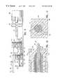
- FIG. 7is a cross-sectional view taken along line 7 — 7 of FIG. 6;
- FIG. 8is a cross-sectional view taken along line 8 — 8 of FIG. 6;
- FIG. 9is a staggered cross-sectional view taken along line 9 — 9 of FIG. 4;
- FIG. 10is a cross-sectional view taken along line 10 — 10 of FIG. 9;
- FIG. 11is a cross-sectional view taken along line 11 — 11 of FIG. 10;
- FIG. 12is a cross-sectional view of the cannula and stylet, taken along line 12 — 12 of FIG. 6;
- FIG. 13is a view taken along line 13 — 13 of FIG. 5, showing a distal end view of the cannula, and a cross-sectional view of the stylet shaft;
- FIG. 14is a cross-sectional view taken along line 14 — 14 of FIG. 12;
- FIG. 15is a cross-sectional view of the base of the biopsy device, taken along line 15 — 15 of FIG. 7;
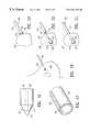
- FIG. 16is a side elevational view of an alternative embodiment of the electrosurgical stylet that may be incorporated in the biopsy device of the present invention.
- FIG. 17is a perspective view of an alternative embodiment of the cannula portion of the biopsy device of the present invention.
- FIG. 18illustrates the step of inserting the biopsy device into tissue for extracting a tissue specimen, in accordance with the method of the present invention
- FIG. 19illustrates the biopsy device positioned to begin extracting a tissue specimen in accordance with the method of the present invention
- FIG. 20illustrates the biopsy device at an intermediate step of the biopsy procedure in accordance with the method of the present invention.
- FIG. 21illustrates the biopsy device at a later intermediate step of the biopsy procedure in accordance with the method of the present invention.
- the biopsy device 100includes a probe 102 , a base unit 104 , an energy source, such as a radio-frequency generator 106 , and a control unit 108 .
- the probe 102includes a stylet 110 and a cannula 112 .
- the stylet 110electrosurgically separates tissue through the use of an electrical current activated at high frequency, such as a frequency in the radio frequency range.
- the stylet 110when electrically activated, ablates tissue adjacent its electrically active components.
- the stylet 110comprising an aspect of the present invention, is shown in FIG. 3 .
- the stylet 110includes a stylet head 122 having a substantially cylindrical body with a substantially hemispherical surface at the distal end of the stylet head 122 .
- the stylet head 122is formed of an electrically insulating material, such as a plastic.
- the stylet head 122is attached to the distal end of a stylet shaft 124 , which is also formed of an electrically insulating material.
- the stylet shaft 124may have a central longitudinal bore through it, preferably along the longitudinal axis of the shaft 124 .
- a conductive metal stylet electrode 126protrudes distally from the stylet head 122 .
- the stylet electrode 126is formed of an arcuate length of electrical conductor that protrudes from diametrically opposite sides of the stylet head 122 , and extends over the hemispherical distal end surface of the stylet head 122 .
- the radius of curvature for the stylet electrode 126is substantially coplanar with the longitudinal axis of the stylet shaft 124 .
- the stylet electrode 126forms a first tissue ablation element for electrosurgically separating tissue so as to create an incision.
- ablationis defined as the process of creating an incision by vaporizing tissue.
- the preferred embodiment described hereinuses electrical energy in the radio frequency range for the ablation process.
- tissue ablationmay also be accomplished with other energy sources, such as microwaves or ultrasound.
- the configuration of the ablation elementsmay differ from the ablation electrodes described hereinbelow.
- the energy supply and control systemmay differ as well. The appropriate variations and modifications in these components to accommodate the alternative energy sources will suggest themselves to those skilled in the pertinent arts.
- the stylet electrode 126merges into a single stylet electrical conductor 128 inside the stylet head 122 .
- the single stylet electrical conductor 128extends through the central bore in the stylet shaft 124 .
- the stylet conductor 128is electrically connected with both ends of the stylet electrode 126 .
- FIG. 16An alternative embodiment of the stylet head is illustrated in FIG. 16 .
- the embodiment illustrated in FIG. 16includes a conical head 130 that has an electrically conductive apex portion 132 that forms the stylet electrode.
- the apex portionis secured to the distal end of an insulative, frustrum-shaped base portion 134 .
- the conical stylet electrode 132which forms the stylet tissue ablation element, is in electrical contact with the stylet conductor 128 (as described above with reference to FIG. 3 ).
- the cannula 112is formed of an elongated hollow outer tube 140 (FIGS. 12, 13 , and 14 ) that has a distal end and a proximal end.
- the longitudinal axis of the cannula 112coincides with the longitudinal axis of the stylet shaft 124 .
- the outer tube 140 of the cannula 112is formed of an electrically nonconductive or insulating material, such as plastic, and may be formed by extrusion.
- the outer tube 140 of the cannulamay be formed of a polyimide.
- the outer surface of the cannula tube 140may be coated with TEFLON® (polytetrafluoroethylene) or similar low-friction polymeric material to reduce sticking between the surface and the surrounding tissue.
- a cannula electrode 142forming a second tissue ablation element.
- the cannula electrode 142may be formed of the distal end of a tubular conductor 144 extending along the length of the cannula 112 , inside the outer tube 140 .
- An electrically insulating inner sleeve 146may cover the inner surface of the tubular conductor 144 .
- the inner cannula sleeve 146may also be formed by extrusion of a polyimide.
- the inner surface of the inner cannula sleeve 146may be coated with a low-friction polymeric material, such as TEFLON®.
- the inner insulating sleeve 146is spaced from the stylet shaft 124 to form an annular passage 148 that is open at the distal end of the cannula 112 .
- the annular passage 148receives tissue samples that are severed by the cannula electrode 142 , as described below.
- the cannula 112will include other elements 152 , 156 , shown in FIGS. 12, 13 , and 14 . These other elements, described below, are not incorporated in the monopolar configuration.
- the stylet 110 and the cannula 112may be moved relative one another along their common longitudinal axis.
- the stylet 110may be moved relative to the cannula 112 between an extended position in which the distal end of the stylet shaft 124 and the stylet head 122 are separated from the distal end of the cannula 112 , and a withdrawn position in which the stylet head 122 abuts or is in close proximity to the distal end of the cannula 112 .
- a primary electrodesuch as the stylet electrode 126
- the primary electrodeis exposed to tissue
- the tissue adjacent the primary electrodeis ablated.
- a return electrical path through the tissueis required, to close the electrical circuit.
- An electrosurgical devicemay be either monopolar or bipolar.
- a monopolar devicethe return electrical path is provided through a return electrode that may be a grounded contact pad that is applied to the exterior of the patient's body at a point remote from where the primary electrode is placed in the body.
- a bipolar devicethe return electrical path is provided from the primary or ablation electrode through a return electrode that is located relatively near the primary electrode.
- the bipolar return electrodeis contained on the same instrument body as the primary electrode.
- a patient return pad 150is attached to the patient's body, and is in electrical contact with the RF generator 106 .
- the patient return pad 150forms a return electrode for the energy delivered by the RF generator 106 to the stylet electrode 126 and the cannula electrode 142 .
- the annular conductor 144 that terminates in the cannula electrode 142is disposed between the external insulating layer of the tube 140 , and the inner insulating sleeve 146 .
- FIG. 1 AA probe 102 ′ used in the bipolar configuration of the biopsy device in accordance with the present invention is shown in FIG. 1 A.
- the return electrical pathis provided through a conductor contained within a bipolar cannula 112 ′.
- FIGS. 12, 13 , 14 , and 1 Athe additional elements of the bipolar cannula 112 ′ are shown.
- a conductive layer 152is contained just under the outer tube 140 , and forms a return path electrode.
- a pair of diametrically-opposed longitudinal side openings or slots 154are provided in the outer tube 140 . These side openings 154 may extend longitudinally along a substantial portion of the length of the cannula 112 ′.
- the conductive layer 152 forming the return path electrodeis exposed to the environment surrounding the cannula 112 ′.
- the return electrode 140is in contact with the tissue, and electrical current may flow through the tissue from the stylet electrode 126 and the cannula electrode 142 to the return electrode 152 .
- the return electrodeis advantageously electrically connected to ground potential.
- the annular cannula conductor 144 in a bipolar implementationis spaced from the return path electrode 152 by an insulating layer 156 of non-conductive material, such as plastic.
- the insulating layer 156electrically isolates the return path electrode 152 from the cannula conductor 144 .
- the cannula electrode 142When activated with a current oscillating at high frequency (such as in the radio frequency range), the cannula electrode 142 ablates tissue adjacent to the cannula electrode. As with the stylet electrode 126 , the operation may be either monopolar or bipolar. For operation in accordance with a bipolar technique, the same return electrode 152 used with the stylet electrode 126 may also be used in conjunction with the cannula electrode 142 . However, those skilled in the art, taking the teaching provided herein, will also recognize that alternative electrical return paths may be provided.
- FIG. 17An alternative embodiment of the cannula is illustrated in FIG. 17 .
- This particular alternative embodimentis illustrated as a monopolar device.
- the illustrated embodimentmay be modified to add a return electrode to implement a bipolar embodiment.
- the cannulais formed of a cannula body 160 .
- a cannula conduit 162extends along the length of the cannula body 160 .
- a length of conductorextends through the cannula conduit 162 , and is formed into a substantially circular cannula electrode 164 that coincides with the distal end of the cannula body 160 .
- the cannula conduit 162may be formed as a groove cut along the length of the cannula body 160 .
- the cannula conduit 162may be formed on the interior surface of the cannula body 160 .
- An energy sourcesuch as the radio-frequency generator 106 , generates the electrical current required for application to the stylet electrode 126 and the cannula electrode 142 .
- the design, construction, and operation of such a generator and control unitare conventional and well-understood by those familiar with electrosurgery technology.
- the base unit 104controls the position and movement of the stylet 110 , the cannula 112 , and the application of the electrical energy generated by the generator and control unit 106 to the stylet electrode 126 and the cannula electrode 142 .
- the base unit 104permits the cannula 112 and stylet 110 to be moved together, and also to be moved separately.
- the probe 102may be moved between an extended position relative to the base unit 104 in which the distal end of the stylet 110 and the distal end of the cannula 112 are relatively farther from the base unit 104 , and a withdrawn position in which the distal end of the stylet 110 and the distal end of the cannula 112 are relatively closer to the base unit 104 .
- the base unit 104may extend the stylet 110 between an extended position relative to the cannula 112 , and a withdrawn position relative to the cannula 112 .
- the base unit 104may be enclosed in a housing 202 (shown in phantom lines in FIG. 1 ).
- the housing 202protects the internal elements of the device.
- the housing 202may be substantially sealed to protect the internal elements of the base unit 104 from contamination during use of the stylet 110 and cannula 112 during a biopsy procedure.
- the housing 202may be selectively removable, or have an access panel (not shown) provided to allow access to certain elements within the base unit 104 .
- the housing 202may be shaped to facilitate hand holding of the device, or it may be configured to be attached to other devices (not shown) for holding the biopsy device in the proper position for conducting the biopsy procedure.
- the base unit 104includes a base 204 to which is fixed an electric motor 206 (preferably a DC motor powered by a power supply 207 ).
- the motor 206is employed for moving the stylet 110 and the cannula 112 relative to the base unit 104 .
- a cannula carrier 210is slidably mounted on the base 204 .
- the cannula 112has a proximal end that is attached to a cannula carrier 210 .
- the cannula carrier 210translates the cannula 112 longitudinally on the base unit 104 .
- the stylet shaft 124has a proximal end that is attached to a stylet carrier 220 that is slidably mounted on the base 204 .
- the stylet carrier 220translates the stylet 110 longitudinally on the base 204 .
- the stylet carrier 220also translates the stylet 110 relative to the cannula 112 .
- the motor 206includes a drive shaft 221 to which is attached a drive screw 222 .
- the drive screw 222is threaded through a screw-driven slide 224 that moves the cannula carrier 210 and the stylet carrier 220 in the manner described below.
- the stylet 110 and the cannula 112are preferably separable from the stylet carrier 220 and the cannula carrier 210 , respectively. In this way, the entire probe unit 102 , including the stylet 110 and cannula 112 , may be replaced upon each use, without having to replace the entire device. This allows the stylet 110 and cannula 112 to be disposable, so that a new, sterile stylet and cannula may be used for each biopsy procedure.
- the proximal end of the stylet 110may be embedded in or attached to a stylet foot 225 , formed of an electrically insulating material, such as plastic.
- the stylet foot 225is removably mounted in the stylet carrier 220 .
- the stylet foot 225may fit into a correspondingly shaped recess in the stylet carrier 220 .
- a stylet retention strip 227having its two ends removably attached to the stylet carrier 220 , and extending across the top of the stylet foot 225 , retains the stylet foot 225 in the stylet carrier 220 .
- the proximal end of the cannula 112may be embedded in or attached to a cannula foot 229 , formed of an electrically insulating material, such as plastic.
- the cannula foot 229is removably mounted in the cannula carrier 210 , such as by being retained in a correspondingly shaped recess in the cannula carrier 210 .
- a cannula retention strip 231having its two ends removably attached to the cannula carrier 210 , and extending across the cannula foot 229 , retains the cannula foot 229 in the cannula carrier 210 .
- the entire probe unit 102including the stylet 110 and the cannula 112 may be made available to medical doctors and hospitals as a single modular unit, ready for attachment to the base unit 104 . In this way, the sterility of the probe unit 102 may be maintained. After completion of a biopsy procedure, the entire probe unit 102 may then be removed from the base unit 104 and discarded in accordance with proper procedures for medical waste.
- FIG. 7An exemplary mounting for the cannula carrier 210 on the base 204 is illustrated in FIG. 7 .
- the base 204includes substantially U-shaped channels 226 along each side thereof Horizontal extensions 228 of the bottom portion of the cannula carrier 210 engage these channels 226 .
- the mounting of the cannula carrier 210 on the base 204preferably provides very little friction between the cannula carrier 210 and the base 204 .
- a low friction mountinghelps to ensure smooth and accurate movement of the cannula carrier 210 relative to the base 204 .
- the mounting of the stylet carrier 220 on the base 204is advantageously similar to the mounting of the cannula carrier 210 .
- An exemplary mounting for the stylet carrier 220 on the base 204is illustrated in FIG. 8 .
- Horizontal extensions 230 of the bottom portion of the stylet carrier 220engage the U-shaped channels 226 formed in the base 204 .
- the mounting of the stylet carrier 220 on the base 204preferably provides very little friction between the stylet carrier 220 and the base 204 .
- a low friction mountinghelps to ensure smooth and accurate movement of the stylet carrier 220 relative to the base 204 .
- the base 204includes a plurality of stops that define the maximum extent of the longitudinal movements of the cannula carrier 210 and the stylet carrier 220 along the base 204 .
- an end piece 232is provided at the distal end of the base 204 .
- the end piece 232forms a forward stop for the cannula carrier 210 .
- An intermediate stop 234is affixed to the base 204 .
- the distal side of the intermediate stop 234forms a rearward stop for the cannula carrier 210
- the proximal side of the intermediate stop 234forms a forward stop for the stylet carrier 220 .
- a back stop 236is affixed to the base 204 as a rearward stop for the stylet carrier 220 .
- the cannula carrier 210may be moved between a withdrawn position (illustrated in FIGS. 4 and 5) and an extended position (illustrated in FIG. 6 ).
- a withdrawn positionillustrated in FIGS. 4 and 5
- an extended positionillustrated in FIG. 6 .
- the distal edge of the cannula carrier 210is spaced from the end piece 232 of the base 204 , and the proximal edge of the cannula carrier 210 abuts against the distal side of the intermediate stop 234 .
- the cannula 112is withdrawn relative to the base 204 .
- the cannula carrier 210When the cannula carrier 210 is in the extended position, the distal edge of the cannula carrier 210 abuts against the end piece 232 , and the cannula 112 is extended distally with respect to the base 204 . As the cannula carrier 210 moves toward the distal end of the base 204 , the cannula 112 moves distally with respect to the base 204 . As the cannula carrier 210 moves toward the proximal end of the base 204 , the cannula 112 moves proximally with respect to the base 204 .
- the stylet carrier 220may also be moved between a withdrawn position (illustrated in FIG. 4) and an extended position (illustrated in FIGS. 5 and 6 ).
- a withdrawn positionillustrated in FIG. 4
- an extended positionillustrated in FIGS. 5 and 6 .
- the distal edge of the stylet carrier 220is spaced from the intermediate stop 234 , and the proximal edge of the stylet carrier 220 abuts against the back stop 236 .
- the stylet 110is withdrawn relative to the base 204 .
- the stylet carrier 220is in the extended position, the distal edge of the stylet carrier 220 abuts against the proximal side of the intermediate stop 234 .
- the stylet 110moves distally with respect to the base 204 .
- the stylet carrier 220moves longitudinally on the base 204 toward the proximal end of the base, the stylet 110 moves proximally with respect to the base 204 .
- a drive mechanism on the base 204moves the cannula carrier 210 and the stylet carrier 220 .
- the drive mechanismincludes the electric motor 206 , the drive screw 222 , and the screw-driven slide 224 .
- the screw-driven slide 224is slidably mounted on the base 204 so as to be movable between a proximal position in which it is relatively near the motor 206 , and a distal position in which the it is relatively remote from the motor 206 , and nearer the distal end of the base 204 .
- the movement of the screw-driven slide 224controls the movement of the cannula carrier 210 and the stylet carrier 220 .
- the screw-driven slide 224is moved along the base 204 by the drive screw 222 , which in turn is driven by the motor 206 by means of the drive shaft 221 .
- the motor 206rotates the drive shaft 221 and the screw 222 , the latter engaging threads (not shown) in the screw-driven slide 224 to move the screw-driven slide 224 along the base 204 .
- the motor 206rotates in a first direction (for example, clockwise)
- the motorturns the drive screw 222 in the same direction, which in turn moves the screw-driven slide 224 from its proximal position toward its distal position.
- the motor 206rotates in the opposite direction
- the rotation of the screw 222moves the screw-driven slide 224 in the opposite direction, toward its proximal position.
- a pair of push rods 240are fixed to the distal side of the screw-driven slide 224 . Each of these push rods 240 extends through openings (not shown) in the stylet carrier 220 , so that the distal ends of the push rods 240 may engage the proximal side of the cannula carrier 210 .
- a spring biasis provided between the screw-driven slide 224 and the stylet carrier 220 . This spring bias tends to maintain a specific predetermined separation between the screw-driven slide 224 and the stylet carrier 220 .
- This spring biasmay be provided by a pair of coil springs 242 , each of which surrounds one of the push rods 240 .
- the biopsy deviceis illustrated in a configuration in which it is set to begin a biopsy procedure.
- the stylet 110is withdrawn relative to the cannula 112 so that the stylet 110 abuts against the distal end of the cannula 112 .
- the cannula 112 and stylet 110are both withdrawn to the full extent possible relative to the base 204 ; that is, they are at their respective proximal limits of travel relative to the base 204 .
- the motor 206As the motor 206 is operated, it turns the screw 222 , which moves the screw-driven slide 224 toward the distal end of the base 204 in the manner described above.
- the springs 242 between the screw-driven slide 224 and the stylet carrier 220maintain the predetermined spacing between the screw-driven slide 224 and the stylet carrier 220 , thus causing the stylet carrier 220 to move toward the distal end of the base 204 at approximately the same rate as the screw-driven slide 224 .
- the cannula carrier 210remains in its original position.
- the stylet 110extends distally relative to the cannula 112 , so that the stylet head 122 separates from the distal end of the cannula 112 .
- the stylet head 122is spaced from the distal end of the cannula 112 , forming a gap between the proximal end of the stylet head 122 and the distal end of the cannula 112 .
- the distal side of the stylet carrier 220contacts the proximal side of the intermediate stop 234 , blocking further movement of the stylet carrier 220 toward the distal end of the base 204 .
- the motor 206continues to rotate the drive screw 222 , it continues to move the screw-driven slide 224 toward the distal end of the base 204 .
- further movement of the stylet carrier 220is blocked.
- the spring bias provided by the springs 242is overcome, the springs 242 compress, and the screw-driven slide 224 moves closer to the stylet carrier 220 .
- the push rods 240extend from the distal side of the stylet carrier 220 and engage the proximal side of the cannula carrier 210 .
- the push rods 240move the cannula carrier 210 toward the distal end of the base 204 .
- This forward (distal) movement of the cannula carrier 210moves the cannula 112 relative to the stylet 110 , closing the gap between the stylet head 122 and the distal end of the cannula 112 , so that the stylet 110 is withdrawn relative to the cannula 112 .
- the energy for the stylet electrode 126 and the cannula electrode 142is supplied by the RF generator 106 .
- the control of activation of the electrodes 126 , 142 , as well as control of the motor 206 that moves the cannular carrier 210 and the stylet carrier 220is provided by the control unit 108 . Accordingly, electrical paths must be provided to conduct energizing current through the base unit 104 from the RF generator 106 to the stylet electrode 126 and the cannula electrode 142 , and to conduct control signals from the control unit 108 to the motor 206 .
- Control signalsare also sent from the control unit 108 to the RF generator 106 to control the activation of the electrodes 126 , 142 .
- a return electrical pathmust be provided for the patient return pad 150 (monopolar configuration) or the return electrode 152 (bipolar configuration).
- the base 204includes a plurality of electrical connectors 260 a , 260 b , 260 c , 260 d for providing electrical connection to the RF generator 106 and the control unit 108 , and to the power supply 207 for the motor 206 .
- a stylet lead 262 , a cannula lead 264 , and (in a bipolar configuration only) a return lead 266each have a first end that is internally connected to separate ones of the connectors 260 a-d .
- the other end of the stylet lead 262is connected to a stylet base contact 268 that is fixed with respect to the base 204 .
- the stylet base contact 268may be embedded in the intermediate stop 234 .
- the other end of the cannula lead 264is connected to a cannula base contact 270 that is fixed with respect to the base 204 .
- the cannula lead contact 264may be embedded in the base end piece 232 .
- the return lead 266is included only in the bipolar configuration. It is not necessary in the monopolar configuration that includes the remote patient return pad 150 (FIG. 1 ). In the monopolar configuration, the connection between the patient return pad 150 and the RF generator and control unit 106 may be provided externally to the base unit 104 .
- the return lead 266 in the bipolar configurationmay be connected to a cannula return base contact 272 that is fixed with respect to the base 204 .
- the return base contact 272may also be embedded in the base end piece 232 .
- the structure of the proximal ends of the stylet 110 and the cannula 112 , and the electrical paths for the stylet conductor 128 and for the cannula conductor 144 ,are illustrated.
- the stylet base contact 268is provided in the intermediate stop 234 .
- a stylet wire 274provides an electrical current path between the stylet base contact 268 and a stylet carrier contact 276 on the stylet carrier 220 .
- the stylet wire 274should be able to accommodate changes in the physical separation between the stylet carrier 220 and the intermediate stop 234 while maintaining a connection between the stylet base contact 268 and the stylet carrier contact 276 .
- the stylet wire 274may be a coiled wire wrapped around a longitudinal pin 278 .
- An opening 279may be provided in the distal side of the stylet carrier 220 to accommodate the coiled stylet wire 274 .
- the stylet carrier contact 276remains in contact with an extension portion 280 of a stylet carrier terminal 282 that is mounted in the stylet foot 225 .
- the stylet carrier terminal 282is in electrical contact with the stylet electrical conductor 128 (see FIGS. 12 and 13) that is enclosed in the stylet shaft 124 .
- the stylet carrier terminal extension portion 280may be formed as a spring to help maintain contact between the stylet carrier terminal extension portion 280 and the stylet carrier contact 276 .
- the stylet carrier terminal 282(with the extension portion 280 ) is fixed within the stylet foot 225 , so that when the stylet foot 225 is removed from the stylet carrier 220 , the stylet carrier terminal 282 (with the extension portion 280 ) is removed with the stylet foot 225 .
- the extension portion 280fits through an opening in the stylet carrier 220 so that the extension portion may contact the stylet carrier contact 276 .
- a similar type of electrical pathis provided for the cannula conductor 142 that is contained in the cannula 112 .
- a cannula carrier terminal 286is fixed within the cannula foot 229 , which is removably mounted in the cannula carrier 210 , as previously described.
- the cannula carrier terminal 286is in electrical contact with the cannula conductor 144 that is enclosed within the cannula tube 140 . (See also FIG. 10.)
- the cannula carrier terminal 286has a spring extension portion 288 that is in contact with a cannula carrier contact 290 when the cannula foot 229 is mounted in the cannula carrier 210 .
- a cannula wire 292provides an electrical current path between the cannula carrier contact 290 with the cannula base contact 270 that is embedded in the base end piece 232 .
- the cannula wire 292is advantageously a coiled wire wrapped around a longitudinal pin 294 .
- a series of electrical contacts and electrical wires substantially similar to those for providing the electrical current path for the cannula conductor 144may be provided in the bipolar configuration in which a return electrode 152 is included in the cannula 112 .
- the return electrical pathmay be included on the opposite side of the cannula carrier 220 for providing contact between the cannula return electrode 152 and the return base contact 272 that is embedded in the base end piece 232 .
- a return electrode 298 embedded in the electrically insulating cannula foot 229(FIGS. 10 and 11) provides a portion of such electrical contact.
- a coiled return wire 302(FIGS. 4 and 5 ) provides an electrical current path between the return electrode 298 and the return base contact 272 embedded in the base end piece 232 .
- the coiled return wire 302may be wrapped around a supporting longitudinal pin 304 .
- FIG. 18a portion of human tissue, such as a human breast 410 , is illustrated containing several tissue masses 420 , which may be suspected tumors or lesions to be examined.
- tissue masses 420which may be suspected tumors or lesions to be examined.
- the portion of the biopsy probe 102 containing the stylet 110 and the distal end of the cannula 112is inserted, using RF current, until the stylet head 122 is near a targeted tissue mass 420 .
- the probe 102is guided toward the targeted tissue mass 420 using conventional imaging techniques, such as ultrasound or X-rays.
- the stylet 110 and the cannula 112are both in their withdrawn (proximal) positions, as illustrated in FIG. 4 . Insertion of the probe 102 toward the targeted tissue mass 420 may be assisted by energizing the stylet electrode 126 to ablate subcutaneous tissue between the skin and the targeted tissue mass 420 . As shown in FIG. 19, while the probe 102 is being inserted to access the targeted tissue mass 420 , the stylet 110 is in its withdrawn position relative to the distal end of the cannula 112 , so that stylet head 122 abuts or substantially abuts the distal end of the cannula 112 , closing the opening in the distal end of the cannula 112 , and thus the passage 148 .
- the stylet electrode 126is then electrically activated to ablate the tissue of the targeted tissue mass 420 .
- the stylet head 122is then pushed through the tissue mass 420 , creating an opening through the tissue mass 420 as the stylet 110 penetrates the tissue mass by moving distally toward its extended position, while the cannula 112 remains in its proximal position, so that the stylet head 122 separates from the distal end of the cannula 112 .
- a gapis thus opened between the stylet head 122 and the distal end of the cannula 112 .
- a portion of the tissue mass 420fills in this gap between the stylet head 122 and the cannula 112 , around the stylet shaft 124 .
- a particular advantage of the arcuate stylet electrode 126is that it creates a narrow “slice” through the targeted tissue mass 420 , thereby facilitating the filling of the aforesaid gap with the portions of the tissue mass on either side of the “slice” that collapse into the gap after being pushed outwardly by the passage of the stylet head 122 .
- the stylet electrode 126may then be deactivated, and the cannula electrode 142 activated. With the cannula electrode 142 activated, the portion of the tissue mass 420 adjacent the cannula electrode 142 is ablated, and the cannula 112 may be pushed forward through the portion of the tissue mass 420 that has filled in around the stylet shaft 124 . As the cannula 112 moves through the tissue mass 420 , it cuts off a portion of the tissue mass 420 , and encases that portion in the annular channel 148 within the cannula 112 .
- the cannula 112has closed the gap between the distal end of the cannula 112 and the stylet head 122 , the severed portion of the tissue mass 420 is contained within the annular channel 148 of the cannula 112 .
- the entire probe 102may then be removed from the tissue mass 420 and the patient's body. Once removed, the cannula 112 and the stylet 110 may again be separated, and the tumor portion contained within the annular channel 148 of the cannula 112 removed for examination and analysis.
- the removal of tissue specimensmay proceed at a slower pace than is typically possible using conventional spring-activated knife cutters.
- additional timecan be allowed between the insertion of the stylet through the suspicious tissue, and the insertion of the annular cannula. This additional time allows more of the tissue to fill the space surrounding the stylet shaft 124 , allowing the cannula electrode 142 to cut a larger sample of the suspicious tissue than has typically been possible using the cutters of the prior art.
- the stylet and cannula of the present inventionare less likely to be deflected as they move through the tissue then are the mechanical cutters of prior art biopsy devices.
- RF energyis preferred to effect the tissue ablation
- other types of energye.g., microwave, ultrasound, or laser
- microwave, ultrasound, or lasermay be employed instead, as mentioned above.
Landscapes
- Health & Medical Sciences (AREA)
- Life Sciences & Earth Sciences (AREA)
- Surgery (AREA)
- Engineering & Computer Science (AREA)
- Medical Informatics (AREA)
- Molecular Biology (AREA)
- Veterinary Medicine (AREA)
- Public Health (AREA)
- Biomedical Technology (AREA)
- Heart & Thoracic Surgery (AREA)
- General Health & Medical Sciences (AREA)
- Animal Behavior & Ethology (AREA)
- Nuclear Medicine, Radiotherapy & Molecular Imaging (AREA)
- Pathology (AREA)
- Neurosurgery (AREA)
- Oral & Maxillofacial Surgery (AREA)
- Physics & Mathematics (AREA)
- Plasma & Fusion (AREA)
- Otolaryngology (AREA)
- Surgical Instruments (AREA)
Abstract
Description
This application is a continuation-in-part of copending U.S. application Ser. No. 09/057,303, titled “Breast Biopsy System and Methods” filed Apr. 8, 1998, by Burbank et al., which is a non-provisional application of provisional patent application Ser. No. 60/076,973, filed Mar. 3, 1998.
Not Applicable
The present invention relates to devices and methods for removing a sample of tissue from a human or animal. In particular, the present invention pertains to devices and methods for conducting a biopsy to remove a sample or specimen of a tumor or lesion for examination and analysis.
In diagnosing and treating certain medical conditions, such as potentially cancerous tumors, it may be desirable to extract from a portion of suspicious tissue, such as a tumor, a specimen of the suspicious tissue for detailed examination and analysis. The process of removing such a specimen of tissue is referred to as a biopsy.
In many instances, the suspicious tissue to be examined is inside the patient's body. For example, the suspicious tissue may be a tumor inside a human breast. To minimize surgical intrusion into the body, it is desirable to be able to insert a small instrument into the body for extracting a portion of the suspicious tissue.
Different types of instruments and procedures have been developed for conducting biopsies to extract a tissue specimen for analysis. One device that has been developed is the fine needle aspirator. This device comprises a hollow needle, the end of which is sharpened. The needle is inserted into the suspicious tissue so that individual cells or clusters of cells of the tissue lodge inside the hollow core of the needle. The needle is then extracted from the patient, and the cells and fluid removed from the needle for a cytological examination. In certain circumstances, however, it may be desirable to extract portions of tissue for a histological examination, a procedure that is not typically feasible using a fine needle aspirator.
Another type of tissue-sampling device for biopsies is exemplified by the device described in U.S. Pat. No. Re. 34,056—Lindgren et al. This type of device includes a forward stylet, which includes at its distal end a sharpened cutting surface. The stylet may be, for example, a needle sized between 12 and 20 gauge. Behind the sharpened cutting end of the stylet, along the shaft thereof, is a groove. A hollow cannula surrounds the stylet, and has its distal end sharpened to form a fine cutting edge. A mechanism is provided to move the stylet and the cannula forward separately. For example, springs may be used for this purpose. Preferably, the stylet and the cannula are moved forward rapidly so that the sharpened ends thereof may efficiently cut the tissue. In operation, the operator of this type of device first causes the stylet to be pushed forward through the tumor or suspect tissue. After the distal end of the stylet has passed through the suspect tissue, a portion of the tissue surrounding the stylet partially fills the groove on the shaft of the stylet. The cannula is then pushed forward so that the sharpened distal end of the cannula cuts off the portion of the tissue that has filled the groove on the shaft of the stylet, and encloses that tissue. The entire device may then be removed from the patient's body, and the tissue trapped in the cannula removed for examination and analysis.
U.S. Pat. No. 5,526,822—Burbank et al. discloses another type of biopsy device that includes the ability to apply a vacuum to the groove in the stylet. This vacuum assists in drawing tissue into the groove, ensuring that a more substantial portion of tissue is severed by the cutting cannula. Using such a system, it is in some cases possible to use a relatively large stylet (e.g., a 7 to 14 gauge needle) to obtain a relatively large tissue sample.
All of the above-described systems use knife edges to cut the tissue. The cutting edge must remain extremely sharp, so that it cuts the tissue cleanly. Moreover, the stylet and the cannula cutter must be propelled forward rapidly to provide a clean cut through the tissue. Elaborate mechanisms are typically employed to provide the rapid forward movement. Because the knife edges move rapidly, however, there is limited time for tissue to fill the groove on the stylet. Therefore, the system sometimes obtains a smaller sample than would be ideal. In addition, variations in tissue density and anatomy may cause the stylet to deflect from its ideal position in relation to the tissue to be penetrated.
Electrosurgical techniques have been used in a variety of circumstances, including certain types of biopsies. In electrosurgery, high frequency electrical energy is applied through a primary electrode to tissue. The electrical energy flows through the tissue to a return electrode. The tissue adjacent to the primary electrode is ablated, to form an opening in the tissue. The return electrode in monopolar electrosurgery may be a large electrode placed on the exterior of the patient's body at a point remote from the primary electrode. In bipolar electrosurgery, the return electrode may be a smaller electrode positioned somewhat near the primary electrode. An exemplary biopsy instrument using electrosurgical techniques is described in International Publication No. WO 98108441.
The present invention, in one aspect, is a novel electrosurgical tissue sampling device, or biopsy device, including a novel electrosurgical stylet. In another aspect, the present invention is a method of using the novel biopsy device to obtain a tissue specimen.
The novel stylet of the present invention includes a shaft that has a proximal end and a distal end. At the distal end of the stylet shaft is a substantially hemispherical head. A stylet electrode extends distally from the stylet head. The stylet electrode may be activated with radio frequency (RF) electrical energy to ablate the tissue adjacent the stylet electrode. A cannula that cooperates with the stylet also has a proximal end and a distal end. An opening is formed at the distal end of the cannula. The distal end of the cannula may be selectively separated from the stylet, or may abut the stylet to close the opening at the distal end of the cannula. Also at the distal end of the cannula is another electrode that also may be activated with radio-frequency electrical energy to ablate the tissue adjacent the distal end of the cannula.
The system may be monopolar, in which the return electrical path is provided by a return electrode attached to the patient's body remote from the device. Alternatively, the system may be bipolar, in which the return electrical path is provided by a return electrode on the device itself The same return electrical path may be used for both the electrode on the stylet and the electrode on the cannula.
In accordance with the method of the present invention, the electrode on the head of the stylet is energized. With the stylet in a withdrawn position abutting against the distal end of the cannula, the stylet and the cannula are pushed through the skin and the underlying tissue, while applying an RF current, until the head of the stylet is adjacent a targeted tissue mass (e.g., a lesion or tumor). Next, the stylet is extended distally from the distal end of the cannula so that its head penetrates the targeted tissue mass, whereby the stylet head and the distal end of the cannula are on opposite sides of the tissue mass. The electrode at the distal end of the cannula is then energized, and the cannula is pushed through the tissue mass toward the stylet head, thereby cutting a “core” through the tissue mass that is captured as a tissue specimen within the distal end of the cannula. The cannula and the stylet are then removed from the patient's body. After the cannula and the stylet have been removed, they may be separated from one another, and the tissue specimen enclosed within the cannula may be removed and examined.
FIG. 1 is a perspective view of a preferred embodiment of a biopsy device constructed in accordance with the present invention;
FIG. 1A is a perspective view of a portion of the cannula and stylet of a modified form of the preferred embodiment of the biopsy device;
FIG. 2 is a distal end view of the device illustrated in FIG. 1, taken from the left side of FIG. 1;
FIG. 3 is a perspective view, partially broken away, of a preferred embodiment of an electrosurgical stylet constructed in accordance with an aspect of the present invention, and incorporated in the device illustrated in FIG. 1;
FIG. 4 is a top view of the device of FIG. 1, with the device set to begin a biopsy procedure in accordance with the method of the present invention;
FIG. 5 is a second top view, similar to the view of FIG. 4, of the device of FIG. 1, with the stylet extended for an intermediate step of a biopsy procedure in accordance with the method of the present invention;
FIG. 6 is a third top view, similar to the view of FIG. 4, of the device of FIG. 1, with both the stylet and the cannula extended for a further stage of a biopsy procedure in accordance with the method of the present invention;
FIG. 7 is a cross-sectional view taken alongline 7—7 of FIG. 6;
FIG. 8 is a cross-sectional view taken alongline 8—8 of FIG. 6;
FIG. 9 is a staggered cross-sectional view taken alongline 9—9 of FIG. 4;
FIG. 10 is a cross-sectional view taken alongline 10—10 of FIG. 9;
FIG. 11 is a cross-sectional view taken alongline 11—11 of FIG. 10;
FIG. 12 is a cross-sectional view of the cannula and stylet, taken alongline 12—12 of FIG. 6;
FIG. 13 is a view taken alongline 13—13 of FIG. 5, showing a distal end view of the cannula, and a cross-sectional view of the stylet shaft;
FIG. 14 is a cross-sectional view taken alongline 14—14 of FIG. 12;
FIG. 15 is a cross-sectional view of the base of the biopsy device, taken alongline 15—15 of FIG. 7;
FIG. 16 is a side elevational view of an alternative embodiment of the electrosurgical stylet that may be incorporated in the biopsy device of the present invention;
FIG. 17 is a perspective view of an alternative embodiment of the cannula portion of the biopsy device of the present invention;
FIG. 18 illustrates the step of inserting the biopsy device into tissue for extracting a tissue specimen, in accordance with the method of the present invention;
FIG. 19 illustrates the biopsy device positioned to begin extracting a tissue specimen in accordance with the method of the present invention;
FIG. 20 illustrates the biopsy device at an intermediate step of the biopsy procedure in accordance with the method of the present invention; and
FIG. 21 illustrates the biopsy device at a later intermediate step of the biopsy procedure in accordance with the method of the present invention.
Referring first to FIG. 1, a particular preferred embodiment of abiopsy device 100, constructed in accordance with the present invention, is illustrated. Thebiopsy device 100 includes aprobe 102, abase unit 104, an energy source, such as a radio-frequency generator 106, and acontrol unit 108.
Theprobe 102 includes astylet 110 and acannula 112. Thestylet 110 electrosurgically separates tissue through the use of an electrical current activated at high frequency, such as a frequency in the radio frequency range. Thestylet 110, when electrically activated, ablates tissue adjacent its electrically active components.
Thestylet 110, comprising an aspect of the present invention, is shown in FIG.3. Thestylet 110 includes astylet head 122 having a substantially cylindrical body with a substantially hemispherical surface at the distal end of thestylet head 122. Thestylet head 122 is formed of an electrically insulating material, such as a plastic. Thestylet head 122 is attached to the distal end of astylet shaft 124, which is also formed of an electrically insulating material. Thestylet shaft 124 may have a central longitudinal bore through it, preferably along the longitudinal axis of theshaft 124.
A conductivemetal stylet electrode 126 protrudes distally from thestylet head 122. In the illustrated embodiment, thestylet electrode 126 is formed of an arcuate length of electrical conductor that protrudes from diametrically opposite sides of thestylet head 122, and extends over the hemispherical distal end surface of thestylet head 122. The radius of curvature for thestylet electrode 126 is substantially coplanar with the longitudinal axis of thestylet shaft 124. Thestylet electrode 126 forms a first tissue ablation element for electrosurgically separating tissue so as to create an incision.
For the purposes of the present description of the invention, the term “ablation”, as used in this specification, is defined as the process of creating an incision by vaporizing tissue. The preferred embodiment described herein uses electrical energy in the radio frequency range for the ablation process. However, tissue ablation may also be accomplished with other energy sources, such as microwaves or ultrasound. In such cases, the configuration of the ablation elements may differ from the ablation electrodes described hereinbelow. The energy supply and control system may differ as well. The appropriate variations and modifications in these components to accommodate the alternative energy sources will suggest themselves to those skilled in the pertinent arts.
Thestylet electrode 126 merges into a single styletelectrical conductor 128 inside thestylet head 122. The single styletelectrical conductor 128 extends through the central bore in thestylet shaft 124. Thestylet conductor 128 is electrically connected with both ends of thestylet electrode 126.
An alternative embodiment of the stylet head is illustrated in FIG.16. The embodiment illustrated in FIG. 16 includes aconical head 130 that has an electrically conductiveapex portion 132 that forms the stylet electrode. The apex portion is secured to the distal end of an insulative, frustrum-shapedbase portion 134. Theconical stylet electrode 132, which forms the stylet tissue ablation element, is in electrical contact with the stylet conductor128 (as described above with reference to FIG.3).
Thecannula 112 is formed of an elongated hollow outer tube140 (FIGS. 12,13, and14) that has a distal end and a proximal end. Preferably, the longitudinal axis of thecannula 112 coincides with the longitudinal axis of thestylet shaft 124. Theouter tube 140 of thecannula 112 is formed of an electrically nonconductive or insulating material, such as plastic, and may be formed by extrusion. For example, theouter tube 140 of the cannula may be formed of a polyimide. The outer surface of thecannula tube 140 may be coated with TEFLON® (polytetrafluoroethylene) or similar low-friction polymeric material to reduce sticking between the surface and the surrounding tissue.
At the distal end of thecannula 112 is acannula electrode 142 forming a second tissue ablation element. Thecannula electrode 142 may be formed of the distal end of atubular conductor 144 extending along the length of thecannula 112, inside theouter tube 140.
An electrically insulatinginner sleeve 146 may cover the inner surface of thetubular conductor 144. Theinner cannula sleeve 146 may also be formed by extrusion of a polyimide. The inner surface of theinner cannula sleeve 146 may be coated with a low-friction polymeric material, such as TEFLON®. The innerinsulating sleeve 146 is spaced from thestylet shaft 124 to form anannular passage 148 that is open at the distal end of thecannula 112. Theannular passage 148 receives tissue samples that are severed by thecannula electrode 142, as described below.
In a bipolar configuration for the probe, described below, thecannula 112 will includeother elements
Thestylet 110 and thecannula 112 may be moved relative one another along their common longitudinal axis. For example, thestylet 110 may be moved relative to thecannula 112 between an extended position in which the distal end of thestylet shaft 124 and thestylet head 122 are separated from the distal end of thecannula 112, and a withdrawn position in which thestylet head 122 abuts or is in close proximity to the distal end of thecannula 112.
Those familiar with electrosurgical techniques will understand that when a high frequency electrical current is applied to a primary electrode, such as thestylet electrode 126, and the primary electrode is exposed to tissue, the tissue adjacent the primary electrode is ablated. To perform such electrosurgery, a return electrical path through the tissue is required, to close the electrical circuit.
An electrosurgical device may be either monopolar or bipolar. With a monopolar device, the return electrical path is provided through a return electrode that may be a grounded contact pad that is applied to the exterior of the patient's body at a point remote from where the primary electrode is placed in the body. With a bipolar device, the return electrical path is provided from the primary or ablation electrode through a return electrode that is located relatively near the primary electrode. The bipolar return electrode is contained on the same instrument body as the primary electrode. Although parts of the present invention are described with reference to a monopolar configuration, and parts are described with reference to a bipolar configuration, those skilled in the art will recognize how the device may be implemented in either configuration.
In the monopolar configuration of the biopsy device illustrated in FIG. 1, apatient return pad 150 is attached to the patient's body, and is in electrical contact with theRF generator 106. Thepatient return pad 150 forms a return electrode for the energy delivered by theRF generator 106 to thestylet electrode 126 and thecannula electrode 142. In the monopolar configuration, theannular conductor 144 that terminates in thecannula electrode 142 is disposed between the external insulating layer of thetube 140, and the innerinsulating sleeve 146.
Aprobe 102′ used in the bipolar configuration of the biopsy device in accordance with the present invention is shown in FIG.1A. In the bipolar configuration, the return electrical path is provided through a conductor contained within abipolar cannula 112′. Referring to FIGS. 12,13,14, and1A, the additional elements of thebipolar cannula 112′ are shown. Aconductive layer 152 is contained just under theouter tube 140, and forms a return path electrode. A pair of diametrically-opposed longitudinal side openings or slots154 (one of which is shown in FIG. 1A) are provided in theouter tube 140. Theseside openings 154 may extend longitudinally along a substantial portion of the length of thecannula 112′. Through theseopenings 154 in theouter tube 140, theconductive layer 152 forming the return path electrode is exposed to the environment surrounding thecannula 112′. Thus, when theprobe 102′ (FIG. 1A) is inserted into a patient's tissue, thereturn electrode 140 is in contact with the tissue, and electrical current may flow through the tissue from thestylet electrode 126 and thecannula electrode 142 to thereturn electrode 152. The return electrode is advantageously electrically connected to ground potential.
Referring now particularly to FIG. 12, theannular cannula conductor 144 in a bipolar implementation is spaced from the return path electrode152 by an insulatinglayer 156 of non-conductive material, such as plastic. The insulatinglayer 156 electrically isolates the return path electrode152 from thecannula conductor 144.
When activated with a current oscillating at high frequency (such as in the radio frequency range), thecannula electrode 142 ablates tissue adjacent to the cannula electrode. As with thestylet electrode 126, the operation may be either monopolar or bipolar. For operation in accordance with a bipolar technique, thesame return electrode 152 used with thestylet electrode 126 may also be used in conjunction with thecannula electrode 142. However, those skilled in the art, taking the teaching provided herein, will also recognize that alternative electrical return paths may be provided.
An alternative embodiment of the cannula is illustrated in FIG.17. This particular alternative embodiment is illustrated as a monopolar device. However, those skilled in the art will recognize that the illustrated embodiment may be modified to add a return electrode to implement a bipolar embodiment. In the alternative embodiment illustrated in FIG. 17, the cannula is formed of acannula body 160. Acannula conduit 162 extends along the length of thecannula body 160. A length of conductor extends through thecannula conduit 162, and is formed into a substantiallycircular cannula electrode 164 that coincides with the distal end of thecannula body 160. Those skilled in the art will readily recognize that other configurations may be used to form the cannula electrode at the distal end of the cannula. For example, thecannula conduit 162 may be formed as a groove cut along the length of thecannula body 160. Similarly, thecannula conduit 162 may be formed on the interior surface of thecannula body 160.
An energy source, such as the radio-frequency generator 106, generates the electrical current required for application to thestylet electrode 126 and thecannula electrode 142. The design, construction, and operation of such a generator and control unit are conventional and well-understood by those familiar with electrosurgery technology.
Thebase unit 104 controls the position and movement of thestylet 110, thecannula 112, and the application of the electrical energy generated by the generator andcontrol unit 106 to thestylet electrode 126 and thecannula electrode 142. Thebase unit 104 permits thecannula 112 andstylet 110 to be moved together, and also to be moved separately. For example, theprobe 102, including both thestylet 110 and thecannula 112, may be moved between an extended position relative to thebase unit 104 in which the distal end of thestylet 110 and the distal end of thecannula 112 are relatively farther from thebase unit 104, and a withdrawn position in which the distal end of thestylet 110 and the distal end of thecannula 112 are relatively closer to thebase unit 104. Furthermore, thebase unit 104 may extend thestylet 110 between an extended position relative to thecannula 112, and a withdrawn position relative to thecannula 112.
Thebase unit 104 may be enclosed in a housing202 (shown in phantom lines in FIG.1). Thehousing 202 protects the internal elements of the device. Thehousing 202 may be substantially sealed to protect the internal elements of thebase unit 104 from contamination during use of thestylet 110 andcannula 112 during a biopsy procedure. However, thehousing 202 may be selectively removable, or have an access panel (not shown) provided to allow access to certain elements within thebase unit 104. In addition, thehousing 202 may be shaped to facilitate hand holding of the device, or it may be configured to be attached to other devices (not shown) for holding the biopsy device in the proper position for conducting the biopsy procedure.
Referring now to FIGS. 1,4,5, and6, thebase unit 104 includes a base204 to which is fixed an electric motor206 (preferably a DC motor powered by a power supply207). Themotor 206 is employed for moving thestylet 110 and thecannula 112 relative to thebase unit 104. Acannula carrier 210 is slidably mounted on thebase 204. Thecannula 112 has a proximal end that is attached to acannula carrier 210. Thecannula carrier 210 translates thecannula 112 longitudinally on thebase unit 104. Thestylet shaft 124 has a proximal end that is attached to astylet carrier 220 that is slidably mounted on thebase 204. Thestylet carrier 220 translates thestylet 110 longitudinally on thebase 204. In combination with thecannula carrier 210, thestylet carrier 220 also translates thestylet 110 relative to thecannula 112. Themotor 206 includes adrive shaft 221 to which is attached adrive screw 222. Thedrive screw 222 is threaded through a screw-drivenslide 224 that moves thecannula carrier 210 and thestylet carrier 220 in the manner described below.
Thestylet 110 and thecannula 112 are preferably separable from thestylet carrier 220 and thecannula carrier 210, respectively. In this way, theentire probe unit 102, including thestylet 110 andcannula 112, may be replaced upon each use, without having to replace the entire device. This allows thestylet 110 andcannula 112 to be disposable, so that a new, sterile stylet and cannula may be used for each biopsy procedure.
The proximal end of thestylet 110 may be embedded in or attached to astylet foot 225, formed of an electrically insulating material, such as plastic. Thestylet foot 225 is removably mounted in thestylet carrier 220. For example, thestylet foot 225 may fit into a correspondingly shaped recess in thestylet carrier 220. Astylet retention strip 227, having its two ends removably attached to thestylet carrier 220, and extending across the top of thestylet foot 225, retains thestylet foot 225 in thestylet carrier 220.
Similarly, the proximal end of thecannula 112 may be embedded in or attached to acannula foot 229, formed of an electrically insulating material, such as plastic. Thecannula foot 229 is removably mounted in thecannula carrier 210, such as by being retained in a correspondingly shaped recess in thecannula carrier 210. Acannula retention strip 231, having its two ends removably attached to thecannula carrier 210, and extending across thecannula foot 229, retains thecannula foot 229 in thecannula carrier 210.
Theentire probe unit 102, including thestylet 110 and thecannula 112 may be made available to medical doctors and hospitals as a single modular unit, ready for attachment to thebase unit 104. In this way, the sterility of theprobe unit 102 may be maintained. After completion of a biopsy procedure, theentire probe unit 102 may then be removed from thebase unit 104 and discarded in accordance with proper procedures for medical waste.
An exemplary mounting for thecannula carrier 210 on thebase 204 is illustrated in FIG.7. Thebase 204 includes substantiallyU-shaped channels 226 along each side thereofHorizontal extensions 228 of the bottom portion of thecannula carrier 210 engage thesechannels 226. The mounting of thecannula carrier 210 on the base204 preferably provides very little friction between thecannula carrier 210 and thebase 204. A low friction mounting helps to ensure smooth and accurate movement of thecannula carrier 210 relative to thebase 204.
The mounting of thestylet carrier 220 on thebase 204 is advantageously similar to the mounting of thecannula carrier 210. An exemplary mounting for thestylet carrier 220 on thebase 204 is illustrated in FIG.8.Horizontal extensions 230 of the bottom portion of thestylet carrier 220 engage theU-shaped channels 226 formed in thebase 204. The mounting of thestylet carrier 220 on the base204 preferably provides very little friction between thestylet carrier 220 and thebase 204. A low friction mounting helps to ensure smooth and accurate movement of thestylet carrier 220 relative to thebase 204.
Thebase 204 includes a plurality of stops that define the maximum extent of the longitudinal movements of thecannula carrier 210 and thestylet carrier 220 along thebase 204. In the particular embodiment illustrated, anend piece 232 is provided at the distal end of thebase 204. Theend piece 232 forms a forward stop for thecannula carrier 210. Anintermediate stop 234 is affixed to thebase 204. The distal side of theintermediate stop 234 forms a rearward stop for thecannula carrier 210, while the proximal side of theintermediate stop 234 forms a forward stop for thestylet carrier 220. Aback stop 236 is affixed to the base204 as a rearward stop for thestylet carrier 220.
Thecannula carrier 210 may be moved between a withdrawn position (illustrated in FIGS. 4 and 5) and an extended position (illustrated in FIG.6). In the withdrawn position, the distal edge of thecannula carrier 210 is spaced from theend piece 232 of thebase 204, and the proximal edge of thecannula carrier 210 abuts against the distal side of theintermediate stop 234. In this withdrawn position, thecannula 112 is withdrawn relative to thebase 204. When thecannula carrier 210 is in the extended position, the distal edge of thecannula carrier 210 abuts against theend piece 232, and thecannula 112 is extended distally with respect to thebase 204. As thecannula carrier 210 moves toward the distal end of thebase 204, thecannula 112 moves distally with respect to thebase 204. As thecannula carrier 210 moves toward the proximal end of thebase 204, thecannula 112 moves proximally with respect to thebase 204.
Thestylet carrier 220 may also be moved between a withdrawn position (illustrated in FIG. 4) and an extended position (illustrated in FIGS.5 and6). In the withdrawn position, the distal edge of thestylet carrier 220 is spaced from theintermediate stop 234, and the proximal edge of thestylet carrier 220 abuts against theback stop 236. In this withdrawn position, thestylet 110 is withdrawn relative to thebase 204. When thestylet carrier 220 is in the extended position, the distal edge of thestylet carrier 220 abuts against the proximal side of theintermediate stop 234. As thestylet carrier 220 moves longitudinally on the base204 toward the distal end of the base, thestylet 110 moves distally with respect to thebase 204. As thestylet carrier 220 moves longitudinally on the base204 toward the proximal end of the base, thestylet 110 moves proximally with respect to thebase 204.
A drive mechanism on the base204 moves thecannula carrier 210 and thestylet carrier 220. In the particular embodiment illustrated, the drive mechanism includes theelectric motor 206, thedrive screw 222, and the screw-drivenslide 224. The screw-drivenslide 224 is slidably mounted on the base204 so as to be movable between a proximal position in which it is relatively near themotor 206, and a distal position in which the it is relatively remote from themotor 206, and nearer the distal end of thebase 204. The movement of the screw-drivenslide 224 controls the movement of thecannula carrier 210 and thestylet carrier 220.
The screw-drivenslide 224 is moved along thebase 204 by thedrive screw 222, which in turn is driven by themotor 206 by means of thedrive shaft 221. Themotor 206 rotates thedrive shaft 221 and thescrew 222, the latter engaging threads (not shown) in the screw-drivenslide 224 to move the screw-drivenslide 224 along thebase 204. When themotor 206 rotates in a first direction (for example, clockwise), the motor turns thedrive screw 222 in the same direction, which in turn moves the screw-drivenslide 224 from its proximal position toward its distal position. When themotor 206 rotates in the opposite direction, the rotation of thescrew 222 moves the screw-drivenslide 224 in the opposite direction, toward its proximal position.
A pair ofpush rods 240 are fixed to the distal side of the screw-drivenslide 224. Each of thesepush rods 240 extends through openings (not shown) in thestylet carrier 220, so that the distal ends of thepush rods 240 may engage the proximal side of thecannula carrier 210. A spring bias is provided between the screw-drivenslide 224 and thestylet carrier 220. This spring bias tends to maintain a specific predetermined separation between the screw-drivenslide 224 and thestylet carrier 220. This spring bias may be provided by a pair ofcoil springs 242, each of which surrounds one of thepush rods 240.
The mechanical operation of thebase unit 104 will now be described with reference to FIGS. 4,5, and6. Referring first to FIG. 4, the biopsy device is illustrated in a configuration in which it is set to begin a biopsy procedure. Thestylet 110 is withdrawn relative to thecannula 112 so that thestylet 110 abuts against the distal end of thecannula 112. Thecannula 112 andstylet 110 are both withdrawn to the full extent possible relative to thebase 204; that is, they are at their respective proximal limits of travel relative to thebase 204.
As themotor 206 is operated, it turns thescrew 222, which moves the screw-drivenslide 224 toward the distal end of the base204 in the manner described above. Thesprings 242 between the screw-drivenslide 224 and thestylet carrier 220 maintain the predetermined spacing between the screw-drivenslide 224 and thestylet carrier 220, thus causing thestylet carrier 220 to move toward the distal end of the base204 at approximately the same rate as the screw-drivenslide 224. However, thecannula carrier 210 remains in its original position. Thus, thestylet 110 extends distally relative to thecannula 112, so that thestylet head 122 separates from the distal end of thecannula 112. This continues until the distal ends of thepush rods 240 contact the proximal side of thecannula carrier 210, as illustrated in FIG.5. At this stage, thestylet head 122 is spaced from the distal end of thecannula 112, forming a gap between the proximal end of thestylet head 122 and the distal end of thecannula 112.
Also at this stage, the distal side of thestylet carrier 220 contacts the proximal side of theintermediate stop 234, blocking further movement of thestylet carrier 220 toward the distal end of thebase 204. As themotor 206 continues to rotate thedrive screw 222, it continues to move the screw-drivenslide 224 toward the distal end of thebase 204. However, further movement of thestylet carrier 220 is blocked. As the spring bias provided by thesprings 242 is overcome, thesprings 242 compress, and the screw-drivenslide 224 moves closer to thestylet carrier 220. As the screw-drivenslide 224 moves closer to thestylet carrier 220, thepush rods 240 extend from the distal side of thestylet carrier 220 and engage the proximal side of thecannula carrier 210. As the screw-drivenslide 224 continues to move toward the distal end of thebase 204, thepush rods 240 move thecannula carrier 210 toward the distal end of thebase 204. This forward (distal) movement of thecannula carrier 210 moves thecannula 112 relative to thestylet 110, closing the gap between thestylet head 122 and the distal end of thecannula 112, so that thestylet 110 is withdrawn relative to thecannula 112.
When the distal end of thecannula 112 contacts the proximal end of stylet head122 (as illustrated in FIG.6), further forward (distal) movement of thecannula carrier 210 should be stopped. Forward movement of thecannula carrier 210 toward the distal end of the base204 may be stopped by stopping themotor 206. The components of the device, including thebase 204 and thestops cannula carrier 210 contacts theend piece 232 of the base to stop further movement of thecannula carrier 210 in the distal (forward) direction.
As noted previously, the energy for thestylet electrode 126 and thecannula electrode 142 is supplied by theRF generator 106. Furthermore, the control of activation of theelectrodes motor 206 that moves thecannular carrier 210 and thestylet carrier 220, is provided by thecontrol unit 108. Accordingly, electrical paths must be provided to conduct energizing current through thebase unit 104 from theRF generator 106 to thestylet electrode 126 and thecannula electrode 142, and to conduct control signals from thecontrol unit 108 to themotor 206. (Control signals are also sent from thecontrol unit 108 to theRF generator 106 to control the activation of theelectrodes
Referring now to FIG. 15, thebase 204 includes a plurality ofelectrical connectors RF generator 106 and thecontrol unit 108, and to thepower supply 207 for themotor 206. Astylet lead 262, acannula lead 264, and (in a bipolar configuration only) areturn lead 266 each have a first end that is internally connected to separate ones of the connectors260a-d. The other end of thestylet lead 262 is connected to astylet base contact 268 that is fixed with respect to thebase 204. For example, thestylet base contact 268 may be embedded in theintermediate stop 234. Similarly, the other end of thecannula lead 264 is connected to acannula base contact 270 that is fixed with respect to thebase 204. For example, thecannula lead contact 264 may be embedded in thebase end piece 232.
Thereturn lead 266 is included only in the bipolar configuration. It is not necessary in the monopolar configuration that includes the remote patient return pad150 (FIG.1). In the monopolar configuration, the connection between thepatient return pad 150 and the RF generator andcontrol unit 106 may be provided externally to thebase unit 104. Thereturn lead 266 in the bipolar configuration may be connected to a cannulareturn base contact 272 that is fixed with respect to thebase 204. For example, thereturn base contact 272 may also be embedded in thebase end piece 232.
Referring next to FIG. 9, the structure of the proximal ends of thestylet 110 and thecannula 112, and the electrical paths for thestylet conductor 128 and for thecannula conductor 144, are illustrated. Referring first to the electrical path for thestylet 110, thestylet base contact 268 is provided in theintermediate stop 234. Astylet wire 274 provides an electrical current path between thestylet base contact 268 and astylet carrier contact 276 on thestylet carrier 220. Because the position of thestylet carrier 220 changes with respect to theintermediate stop 234, thestylet wire 274 should be able to accommodate changes in the physical separation between thestylet carrier 220 and theintermediate stop 234 while maintaining a connection between thestylet base contact 268 and thestylet carrier contact 276. For example, thestylet wire 274 may be a coiled wire wrapped around alongitudinal pin 278. Anopening 279 may be provided in the distal side of thestylet carrier 220 to accommodate the coiledstylet wire 274.
Thestylet carrier contact 276 remains in contact with anextension portion 280 of astylet carrier terminal 282 that is mounted in thestylet foot 225. Thestylet carrier terminal 282, in turn, is in electrical contact with the stylet electrical conductor128 (see FIGS. 12 and 13) that is enclosed in thestylet shaft 124. The stylet carrierterminal extension portion 280 may be formed as a spring to help maintain contact between the stylet carrierterminal extension portion 280 and thestylet carrier contact 276. The stylet carrier terminal282 (with the extension portion280) is fixed within thestylet foot 225, so that when thestylet foot 225 is removed from thestylet carrier 220, the stylet carrier terminal282 (with the extension portion280) is removed with thestylet foot 225. Theextension portion 280 fits through an opening in thestylet carrier 220 so that the extension portion may contact thestylet carrier contact 276.
A similar type of electrical path is provided for thecannula conductor 142 that is contained in thecannula 112. Acannula carrier terminal 286 is fixed within thecannula foot 229, which is removably mounted in thecannula carrier 210, as previously described. Thecannula carrier terminal 286 is in electrical contact with thecannula conductor 144 that is enclosed within thecannula tube 140. (See also FIG. 10.) Thecannula carrier terminal 286 has aspring extension portion 288 that is in contact with acannula carrier contact 290 when thecannula foot 229 is mounted in thecannula carrier 210. Acannula wire 292 provides an electrical current path between thecannula carrier contact 290 with thecannula base contact 270 that is embedded in thebase end piece 232. Again, because the position of thecannula slide 210 changes with respect to thebase end piece 232, thecannula wire 292 is advantageously a coiled wire wrapped around alongitudinal pin 294.
A series of electrical contacts and electrical wires substantially similar to those for providing the electrical current path for thecannula conductor 144 may be provided in the bipolar configuration in which areturn electrode 152 is included in thecannula 112. For example, the return electrical path may be included on the opposite side of thecannula carrier 220 for providing contact between thecannula return electrode 152 and thereturn base contact 272 that is embedded in thebase end piece 232. Areturn electrode 298 embedded in the electrically insulating cannula foot229 (FIGS. 10 and 11) provides a portion of such electrical contact. A coiled return wire302 (FIGS. 4 and5) provides an electrical current path between thereturn electrode 298 and thereturn base contact 272 embedded in thebase end piece 232. The coiledreturn wire 302 may be wrapped around a supportinglongitudinal pin 304.
A method of performing a biopsy in accordance with an aspect of the present invention will be described with reference to FIGS. 18 through 21. Referring first to FIG. 18, a portion of human tissue, such as ahuman breast 410, is illustrated containingseveral tissue masses 420, which may be suspected tumors or lesions to be examined. Through an incision in thetissue 410, the portion of thebiopsy probe 102 containing thestylet 110 and the distal end of thecannula 112 is inserted, using RF current, until thestylet head 122 is near a targetedtissue mass 420. Theprobe 102 is guided toward the targetedtissue mass 420 using conventional imaging techniques, such as ultrasound or X-rays. Thestylet 110 and thecannula 112 are both in their withdrawn (proximal) positions, as illustrated in FIG.4. Insertion of theprobe 102 toward the targetedtissue mass 420 may be assisted by energizing thestylet electrode 126 to ablate subcutaneous tissue between the skin and the targetedtissue mass 420. As shown in FIG. 19, while theprobe 102 is being inserted to access the targetedtissue mass 420, thestylet 110 is in its withdrawn position relative to the distal end of thecannula 112, so thatstylet head 122 abuts or substantially abuts the distal end of thecannula 112, closing the opening in the distal end of thecannula 112, and thus thepassage 148.
Thestylet electrode 126 is then electrically activated to ablate the tissue of the targetedtissue mass 420. Thestylet head 122 is then pushed through thetissue mass 420, creating an opening through thetissue mass 420 as thestylet 110 penetrates the tissue mass by moving distally toward its extended position, while thecannula 112 remains in its proximal position, so that thestylet head 122 separates from the distal end of thecannula 112. A gap is thus opened between thestylet head 122 and the distal end of thecannula 112. A portion of thetissue mass 420 fills in this gap between thestylet head 122 and thecannula 112, around thestylet shaft 124. A particular advantage of thearcuate stylet electrode 126 is that it creates a narrow “slice” through the targetedtissue mass 420, thereby facilitating the filling of the aforesaid gap with the portions of the tissue mass on either side of the “slice” that collapse into the gap after being pushed outwardly by the passage of thestylet head 122.
Thestylet electrode 126 may then be deactivated, and thecannula electrode 142 activated. With thecannula electrode 142 activated, the portion of thetissue mass 420 adjacent thecannula electrode 142 is ablated, and thecannula 112 may be pushed forward through the portion of thetissue mass 420 that has filled in around thestylet shaft 124. As thecannula 112 moves through thetissue mass 420, it cuts off a portion of thetissue mass 420, and encases that portion in theannular channel 148 within thecannula 112. Once thecannula 112 has closed the gap between the distal end of thecannula 112 and thestylet head 122, the severed portion of thetissue mass 420 is contained within theannular channel 148 of thecannula 112. Theentire probe 102 may then be removed from thetissue mass 420 and the patient's body. Once removed, thecannula 112 and thestylet 110 may again be separated, and the tumor portion contained within theannular channel 148 of thecannula 112 removed for examination and analysis.
Using the device and method of the present invention, the removal of tissue specimens may proceed at a slower pace than is typically possible using conventional spring-activated knife cutters. In particular, additional time can be allowed between the insertion of the stylet through the suspicious tissue, and the insertion of the annular cannula. This additional time allows more of the tissue to fill the space surrounding thestylet shaft 124, allowing thecannula electrode 142 to cut a larger sample of the suspicious tissue than has typically been possible using the cutters of the prior art. In addition, the stylet and cannula of the present invention are less likely to be deflected as they move through the tissue then are the mechanical cutters of prior art biopsy devices.
The specific embodiments described and illustrated above are exemplary, and not exhaustive or exclusive. Those familiar with the art will recognize that various modifications may be made to the specific embodiments described above without departing from the concepts of the present invention. For example, those skilled in the art will recognize that various modifications may be made to the base unit, and that different configurations may be used for controlling the movement and position of the stylet and the cannula. In addition, different specific shapes of the stylet, the stylet head, and cannula may be incorporated into a system implementing the present invention. Furthermore, although an electric motor is the preferred mechanism for driving the cannula carrier and the stylet carrier, other mechanisms, such as mechanical springs or pneumatic mechanisms, may be employed. Indeed, a simplified device may employ manually-driven carriers. Moreover, although RF energy is preferred to effect the tissue ablation, other types of energy (e.g., microwave, ultrasound, or laser) may be employed instead, as mentioned above. These and other modifications and variations that may suggest themselves are considered to be within the spirit and scope of the present invention, as defined in the claims that follow.
Claims (37)
1. A biopsy device, comprising:
an elongate cannula having an open distal end and a proximal end;
a first tissue ablation element disposed on the open distal end of the cannula;
an elongate stylet slidably disposed within the cannula configured for axial translation between an extended position and a withdrawn position; and
a second tissue ablation element disposed on a distal end of the stylet.
2. The biopsy device of claim1, wherein the stylet comprises:
a shaft having a proximal end and a distal end; and
a substantially hemispherical stylet head disposed on the distal end of the shaft, the second tissue ablation element extending over a distal end surface of the stylet head.
3. The biopsy device of claim2, wherein the first and second tissue ablation elements are activated by radio frequency electrical current.
4. The biopsy device of claim3, wherein the second ablation element comprises an arcuate length of electrical conductor having a radius of curvature that is substantially coplanar with a longitudinal axis of the shaft.
5. The biopsy device of claim1, wherein the stylet comprises:
a shaft having a proximal end and a distal end; and
a conical head terminating in an apex portion, wherein the second tissue ablation element includes the apex portion.
6. The biopsy device of claim1, further comprising a stylet translation mechanism coupled to the stylet for translating the stylet within the cannula between the withdrawn and extended positions.
7. The biopsy device of claim6, wherein the biopsy device includes a base, wherein the stylet has a proximal end extending proximally from the proximal end of the cannula, and wherein the translation mechanism comprises:
a carrier connected to the proximal end of the stylet and movably mounted on the base, the carrier being movable on the base between a first position in which the stylet is in the withdrawn position and a second position in which the stylet is in the extended position; and
a carrier drive, coupled to the carrier, for moving the carrier between the first and second positions.
8. The biopsy device of claim7, wherein the carrier drive is driven by a motor.
9. The biopsy device of claim8, wherein the motor has a drive shaft, and wherein the carrier drive comprises:
a drive screw coupled for rotation with the drive shaft;
a screw-driven mechanism coupled between the drive screw and the carrier, whereby rotation of the drive screw in a first direction moves the carrier from the first position to the second position.
10. An electrosurgical stylet, comprising:
a shaft having a proximal end and a distal end;
a stylet head disposed on the distal end of the shaft; and
a tissue ablation electrode formed of an arcuate length of electrical conductor which extends over a distal end surface of the stylet head spaced distally from the distal end surface.
11. The electrosurgical stylet of claim10, wherein the stylet head has a substantially hemispherical distal end surface.
12. The electrosurgical stylet of claim10, wherein the tissue ablation electrode comprises an arcuate length of electrical conductor having a radius of curvature that is substantially coplanar with a longitudinal axis of the shaft.
13. The electrosurgical stylet of claim10, wherein the tissue ablation electrode is formed from a length of electrical conductor which protrudes from diametrically opposed sides of the stylet head and extends over the distal end surface of the stylet head spaced distally from the distal end surface.
14. A biopsy device, comprising:
a base having a proximal end and a distal end;
an elongate cannula having an open distal end and an open proximal end mounted on the base for axial translation thereon between a proximal position and a distal position;
an elongate stylet slidably disposed within the cannula, the stylet having a proximal end that extends proximally from the proximal end of the cannula and that is mounted on the base for axial translation between a withdrawn position and an extended position with respect to the cannula;
a first tissue ablation element disposed on the open distal end of the cannula;
a second tissue ablation element disposed on a distal end of the stylet; and
a translation mechanism for sequentially moving the stylet from its withdrawn position to its extended position, and then moving the cannula from its proximal position to its distal position.
15. The biopsy device of claim14, wherein the translation mechanism comprises:
a first carrier, connected to the proximal end of the stylet and slidably mounted on the base for translation thereon between a first position corresponding to the withdrawn position of the stylet and a second position corresponding to the extended position of the stylet;
a second carrier, connected to the proximal end of the cannula and slidably mounted on the base between the first carrier and the distal end of the base, for translation thereon between a proximal position corresponding to the proximal position of the cannula and a distal position corresponding to the distal position of the cannula; and
a carrier drive engageable with the first and second carriers, for sequentially driving the first carrier from its first position to its second position and then driving the second carrier from its proximal position to its distal position.
16. The biopsy device of claim15, wherein the carrier drive comprises:
a motor having a drive shaft;
a drive screw coupled for rotation with the drive shaft;
a screw driven mechanism coupled between the drive screw and the first carrier, whereby rotation of the drive screw in a first direction moves the first carrier from the first position to the second position.
17. The biopsy device of claim15, wherein the stylet is removably mounted in the first carrier and the cannula is removably mounted in the second carrier.
18. The biopsy device of claim14, wherein the first and second tissue ablation elements are activated by radio frequency electrical current.
19. The biopsy device of claim18, wherein the first ablation element is an ablation electrode, and wherein the cannula includes a return electrode spaced from the ablation electrode.
20. The biopsy device of claim19, wherein the cannula includes an elongate aperture along a portion of its length, and wherein the return electrode comprises a length of conductor contained within the cannula, at least a portion of the conductor being exposed through the elongate aperture.
21. The biopsy device of claim14, wherein the stylet comprises:
a shaft having a proximal end and a distal end and defining a longitudinal axis therebetween; and
a substantially hemispherical stylet head disposed on the distal end of the shaft with the second tissue ablation element extending distally from the head.
22. The biopsy device of claim21, wherein the first and second ablation elements are energized by radio frequency electrical current, and wherein the second ablation element comprises an arcuate length of electrical conductor having a radius of curvature that is substantially coplanar with the longitudinal axis of the shaft.
23. A method of taking a tissue sample from a targeted subcutaneous tissue mass within the body of a patient, comprising:
a) providing a probe comprising:
a cannula having an open distal end,
a stylet disposed within the probe for axial movement therein between a withdrawn position and an extended position relative to the distal end of the cannula,
a first tissue ablation element disposed on the open distal end of the cannula, and
a second tissue ablation element disposed on a distal end of the stylet;
b) while activating the second ablation element with energy of a type and quantity that causes tissue ablation, advancing the probe by tissue ablation, with the stylet in the withdrawn position, into the patient's body toward the targeted tissue mass;
c) with the second ablation element activated, moving the stylet to its extended position so that it penetrates the targeted tissue mass by ablation, while creating a gap between the second ablation element and the distal end of the cannula that fills with a portion of the tissue from the targeted tissue mass;
d) while activating the first ablation element with energy of a type and quantity that causes tissue ablation, moving the cannula distally relative to the stylet so as to close the gap, thereby capturing the portion of the tissue mass within the cannula; and
e) withdrawing the probe from the body with the portion of the tissue mass captured within the cannula.
24. The method of claim23, wherein the first and second ablation elements are activated with radio frequency electrical current.
25. The method of claim23, wherein the stylet and the cannula are movably mounted on a base, wherein the cannula is movable between a proximal position and a distal position relative to the base, wherein the cannula is in the proximal position during advancing the probe and of moving the stylet, and wherein moving the cannula includes moving the cannula from its proximal position to its distal position.
26. The method of claim23, wherein moving the stylet and moving the cannula are performed by an electrically powered driving mechanism.
27. The method of claim23, wherein moving the stylet creates a narrow slice through the targeted tissue mass.
28. An elongated device for accessing a tissue site within a patient, comprising:
a. an elongated shaft which has proximal and distal ends;
b. a thin, tissue cutting electrode which is secured to the distal end of the shaft and which has an activatable arcuate portion spaced distally from the distal end of the shaft; and
c. an elongated electrical conductor which has one end electrically connected to the thin, tissue cutting electrode secured to the distal end of the elongated shaft and one end configured to be electrically connected to a high frequency electrical power source.
29. The elongated accessing device of claim28 wherein the thin, tissue cutting electrode secured to the distal end of the elongated shaft is formed of conductive metallic material.
30. The elongated accessing device of claim28 wherein the elongated shaft is provided with an arcuate cutting member at a location spaced proximally from the distal end of the elongated shaft.
31. The elongated accessing device of claim30 wherein the arcuate proximal cutting member is an electrode.
32. The elongated accessing device of claim30 wherein an electrical conductor is provided having one end electrically connected to the arcuate cutting member and open end configured to be electrically connected to a high frequency electrical power source.
33. The elongated accessing device of claim30 wherein the arcuate cutting member is rotatable about a longitudinal axis of the elongated shaft.
34. The elongated accessing device of claim28, wherein the distal end of the elongated shaft has a substantially hemispherical surface.
35. The accessing device of claim28, further comprising a translation mechanism coupled to the elongated shaft for translating the accessing device between the withdrawn and extended positions.
36. The accessing device of claim28, wherein the tissue cutting electrode comprises an arcuate length of electrical conductor having a radius of curvature that is substantially coplanar with a longitudinal axis of the shaft.
37. The accessing device of claim28, wherein the tissue cutting electrode is formed from a length of electrical conductor which protrudes from diametrically opposed sides of the distal end of the elongated shaft and extends over the surface of the distal end.
Priority Applications (27)
| Application Number | Priority Date | Filing Date | Title |
|---|---|---|---|
| US09/159,467US6261241B1 (en) | 1998-03-03 | 1998-09-23 | Electrosurgical biopsy device and method |
| US09/238,965US6659105B2 (en) | 1998-02-26 | 1999-01-27 | Tissue specimen isolating and damaging device and method |
| JP2000573660AJP2002526191A (en) | 1998-09-23 | 1999-09-17 | Electrosurgical biopsy device and method |
| CA002344641ACA2344641A1 (en) | 1998-09-23 | 1999-09-17 | Electrosurgical biopsy device and method |
| AU59266/99AAU5926699A (en) | 1998-09-23 | 1999-09-17 | Electrosurgical biopsy device and method |
| PCT/US1999/021416WO2000016697A2 (en) | 1998-09-23 | 1999-09-17 | Electrosurgical biopsy device and method |
| EP99946972AEP1115345A2 (en) | 1998-09-23 | 1999-09-17 | Electrosurgical biopsy device and method |
| US09/477,255US6471700B1 (en) | 1998-04-08 | 2000-01-04 | Apparatus and method for accessing biopsy site |
| US09/619,867US6517498B1 (en) | 1998-03-03 | 2000-07-20 | Apparatus and method for tissue capture |
| US09/717,176US6497706B1 (en) | 1998-03-03 | 2000-11-16 | Biopsy device and method of use |
| US09/727,112US6638234B2 (en) | 1998-03-03 | 2000-11-29 | Sentinel node location and biopsy |
| US09/753,529US6540695B1 (en) | 1998-04-08 | 2000-12-28 | Biopsy anchor device with cutter |
| US09/819,185US6689071B2 (en) | 1998-03-03 | 2001-03-27 | Electrosurgical biopsy device and method |
| US09/880,218US6679851B2 (en) | 1998-09-01 | 2001-06-12 | Tissue accessing and anchoring device and method |
| US09/884,349US6676658B2 (en) | 1998-04-08 | 2001-06-18 | Tissue specimen isolating and damaging device and method |
| US09/916,937US6997885B2 (en) | 1998-04-08 | 2001-07-27 | Dilation devices and methods for removing tissue specimens |
| US10/056,453US7377902B2 (en) | 1998-04-08 | 2002-01-23 | Biopsy anchor device with cutter |
| US10/061,706US6716179B2 (en) | 1998-03-03 | 2002-01-30 | Sentinel node location and biopsy |
| US10/136,700US6875182B2 (en) | 1998-03-03 | 2002-04-30 | Electrosurgical specimen-collection system |
| US10/179,933US6758848B2 (en) | 1998-03-03 | 2002-06-21 | Apparatus and method for accessing a body site |
| US10/650,027US7625347B2 (en) | 1998-03-03 | 2003-08-27 | Electrosurgical biopsy device and method |
| US10/729,086US7282034B2 (en) | 1998-09-01 | 2003-12-05 | Tissue accessing and anchoring device and method |
| US10/756,178US7357801B2 (en) | 1998-04-08 | 2004-01-13 | Tissue specimen isolating and damaging device and method |
| US10/933,182US7651467B2 (en) | 1998-04-08 | 2004-09-02 | Dilation devices and methods for removing tissue specimens |
| US11/098,963US20050187489A1 (en) | 1998-03-03 | 2005-04-04 | Electrosurgical specimen-collection system |
| US11/807,293US8147487B2 (en) | 1998-03-03 | 2007-05-25 | Apparatus and method for accessing a body site |
| US12/148,818US20080287828A1 (en) | 1998-04-08 | 2008-04-23 | Biopsy anchor device with cutter |
Applications Claiming Priority (3)
| Application Number | Priority Date | Filing Date | Title |
|---|---|---|---|
| US7697398P | 1998-03-03 | 1998-03-03 | |
| US09/057,303US6331166B1 (en) | 1998-03-03 | 1998-04-08 | Breast biopsy system and method |
| US09/159,467US6261241B1 (en) | 1998-03-03 | 1998-09-23 | Electrosurgical biopsy device and method |
Related Parent Applications (6)
| Application Number | Title | Priority Date | Filing Date |
|---|---|---|---|
| US09/057,303Continuation-In-PartUS6331166B1 (en) | 1998-02-26 | 1998-04-08 | Breast biopsy system and method |
| US09/146,185Continuation-In-PartUS6540693B2 (en) | 1998-02-26 | 1998-09-01 | Methods and apparatus for securing medical instruments to desired locations in a patients body |
| US09/196,125Continuation-In-PartUS6454727B1 (en) | 1998-03-03 | 1998-11-20 | Tissue acquisition system and method of use |
| US09/238,965Continuation-In-PartUS6659105B2 (en) | 1998-02-26 | 1999-01-27 | Tissue specimen isolating and damaging device and method |
| US09/356,187Continuation-In-PartUS6312429B1 (en) | 1998-03-03 | 1999-07-16 | Electrosurgical lesion location device |
| US09/477,255Continuation-In-PartUS6471700B1 (en) | 1998-03-03 | 2000-01-04 | Apparatus and method for accessing biopsy site |
Related Child Applications (14)
| Application Number | Title | Priority Date | Filing Date |
|---|---|---|---|
| US09/057,303Continuation-In-PartUS6331166B1 (en) | 1998-02-26 | 1998-04-08 | Breast biopsy system and method |
| US09/146,185Continuation-In-PartUS6540693B2 (en) | 1998-02-26 | 1998-09-01 | Methods and apparatus for securing medical instruments to desired locations in a patients body |
| US09/238,965Continuation-In-PartUS6659105B2 (en) | 1998-02-26 | 1999-01-27 | Tissue specimen isolating and damaging device and method |
| US09/241,936Continuation-In-PartUS6161034A (en) | 1998-04-08 | 1999-02-02 | Methods and chemical preparations for time-limited marking of biopsy sites |
| US09/356,187Continuation-In-PartUS6312429B1 (en) | 1998-03-03 | 1999-07-16 | Electrosurgical lesion location device |
| US09/477,255Continuation-In-PartUS6471700B1 (en) | 1998-03-03 | 2000-01-04 | Apparatus and method for accessing biopsy site |
| US61868500AContinuation-In-Part | 1998-03-03 | 2000-07-18 | |
| US09/717,176Continuation-In-PartUS6497706B1 (en) | 1998-03-03 | 2000-11-16 | Biopsy device and method of use |
| US09/727,112Continuation-In-PartUS6638234B2 (en) | 1998-03-03 | 2000-11-29 | Sentinel node location and biopsy |
| US09/819,185ContinuationUS6689071B2 (en) | 1998-03-03 | 2001-03-27 | Electrosurgical biopsy device and method |
| US09/880,218Continuation-In-PartUS6679851B2 (en) | 1998-09-01 | 2001-06-12 | Tissue accessing and anchoring device and method |
| US09/884,349Continuation-In-PartUS6676658B2 (en) | 1998-04-08 | 2001-06-18 | Tissue specimen isolating and damaging device and method |
| US09/916,937Continuation-In-PartUS6997885B2 (en) | 1998-04-08 | 2001-07-27 | Dilation devices and methods for removing tissue specimens |
| US10/056,453Continuation-In-PartUS7377902B2 (en) | 1998-04-08 | 2002-01-23 | Biopsy anchor device with cutter |
Publications (1)
| Publication Number | Publication Date |
|---|---|
| US6261241B1true US6261241B1 (en) | 2001-07-17 |
Family
ID=22572720
Family Applications (3)
| Application Number | Title | Priority Date | Filing Date |
|---|---|---|---|
| US09/159,467Expired - LifetimeUS6261241B1 (en) | 1998-02-26 | 1998-09-23 | Electrosurgical biopsy device and method |
| US09/819,185Expired - LifetimeUS6689071B2 (en) | 1998-03-03 | 2001-03-27 | Electrosurgical biopsy device and method |
| US10/650,027Expired - Fee RelatedUS7625347B2 (en) | 1998-03-03 | 2003-08-27 | Electrosurgical biopsy device and method |
Family Applications After (2)
| Application Number | Title | Priority Date | Filing Date |
|---|---|---|---|
| US09/819,185Expired - LifetimeUS6689071B2 (en) | 1998-03-03 | 2001-03-27 | Electrosurgical biopsy device and method |
| US10/650,027Expired - Fee RelatedUS7625347B2 (en) | 1998-03-03 | 2003-08-27 | Electrosurgical biopsy device and method |
Country Status (6)
| Country | Link |
|---|---|
| US (3) | US6261241B1 (en) |
| EP (1) | EP1115345A2 (en) |
| JP (1) | JP2002526191A (en) |
| AU (1) | AU5926699A (en) |
| CA (1) | CA2344641A1 (en) |
| WO (1) | WO2000016697A2 (en) |
Cited By (159)
| Publication number | Priority date | Publication date | Assignee | Title |
|---|---|---|---|---|
| US20020022850A1 (en)* | 1997-07-24 | 2002-02-21 | Mcguckin James F. | Breast surgery method and apparatus |
| US20020042594A1 (en)* | 1998-03-30 | 2002-04-11 | Paul Lum | Apparatus and method for penetration with shaft having a sensor for sensing penetration depth |
| US20020058882A1 (en)* | 1998-06-22 | 2002-05-16 | Artemis Medical, Incorporated | Biopsy localization method and device |
| US6409742B1 (en) | 1998-08-19 | 2002-06-25 | Artemis Medical, Inc. | Target tissue localization device and method |
| US6409726B1 (en)* | 1999-11-08 | 2002-06-25 | Alan G. Ellman | Electrosurgical instrument for ear surgery |
| US6471659B2 (en) | 1999-12-27 | 2002-10-29 | Neothermia Corporation | Minimally invasive intact recovery of tissue |
| US20020198554A1 (en)* | 2001-03-14 | 2002-12-26 | Whitman Michael P. | Trocar device |
| US6530923B1 (en) | 1998-02-10 | 2003-03-11 | Artemis Medical, Inc. | Tissue removal methods and apparatus |
| WO2003020136A1 (en)* | 2001-08-28 | 2003-03-13 | Rex Medical, L.P. | Tissue biopsy apparatus |
| US20030083656A1 (en)* | 2000-11-07 | 2003-05-01 | George Morrison | Tissue separator assembly and method |
| US20030088191A1 (en)* | 2001-06-12 | 2003-05-08 | Freeman Dominique M. | Blood sampling device with diaphragm actuated lancet |
| US6589240B2 (en) | 2001-08-28 | 2003-07-08 | Rex Medical, L.P. | Tissue biopsy apparatus with collapsible cutter |
| US20030153939A1 (en)* | 2000-03-04 | 2003-08-14 | Michael Fritz | Blood lancet with hygienic tip protection |
| US6623437B2 (en) | 2001-08-28 | 2003-09-23 | Rex Medical, L.P. | Tissue biopsy apparatus |
| US6626903B2 (en) | 1997-07-24 | 2003-09-30 | Rex Medical, L.P. | Surgical biopsy device |
| US20030195549A1 (en)* | 1998-08-20 | 2003-10-16 | Davison Thomas W. | Cannula for receiving surgical instruments |
| US20030199753A1 (en)* | 2002-04-23 | 2003-10-23 | Ethicon Endo-Surgery | MRI compatible biopsy device with detachable probe |
| US20030199903A1 (en)* | 2002-04-19 | 2003-10-23 | Pelikan Technologies, Inc. | Method and apparatus for penetrating tissue |
| US20030199900A1 (en)* | 2002-04-19 | 2003-10-23 | Pelikan Technologies, Inc. | Method and apparatus for penetrating tissue |
| US20030199754A1 (en)* | 2002-04-23 | 2003-10-23 | Ethicon Endo-Surgery | Method for using an MRI compatible biopsy device with detachable probe |
| US20030199785A1 (en)* | 2002-04-23 | 2003-10-23 | Ethicon Endo-Surgery | Localization mechanism for an MRI compatible biopsy device |
| US20030204188A1 (en)* | 2001-11-07 | 2003-10-30 | Artemis Medical, Inc. | Tissue separating and localizing catheter assembly |
| US20030225401A1 (en)* | 2002-05-31 | 2003-12-04 | Eggers Philip E. | Electrosurgery with infiltration anesthesia |
| US20030229292A1 (en)* | 2002-06-06 | 2003-12-11 | Hibner John A. | Perimeter cut biopsy probe |
| US20030233112A1 (en)* | 2001-06-12 | 2003-12-18 | Don Alden | Self optimizing lancing device with adaptation means to temporal variations in cutaneous properties |
| US6676658B2 (en)* | 1998-04-08 | 2004-01-13 | Senorx, Inc. | Tissue specimen isolating and damaging device and method |
| US20040010279A1 (en)* | 2002-04-19 | 2004-01-15 | Freeman Dominique M. | Device and method for variable speed lancet |
| US6689071B2 (en)* | 1998-03-03 | 2004-02-10 | Senorx, Inc. | Electrosurgical biopsy device and method |
| US20040049219A1 (en)* | 2002-04-19 | 2004-03-11 | Pelikan Technologies, Inc. | Methods and apparatus for lancet actuation |
| US20040073140A1 (en)* | 1996-05-17 | 2004-04-15 | Douglas Joel S. | Methods and apparatus for expressing body fluid from an incision |
| US20040077972A1 (en)* | 2002-10-18 | 2004-04-22 | Mark Tsonton | Localization mechanism for an MRI compatible biopsy device |
| US6770070B1 (en)* | 2000-03-17 | 2004-08-03 | Rita Medical Systems, Inc. | Lung treatment apparatus and method |
| US20040153002A1 (en)* | 2003-01-31 | 2004-08-05 | Schramm John B. | Integrated biopsy needle assembly |
| US20040167511A1 (en)* | 2003-02-25 | 2004-08-26 | Artemis Medical, Inc. | Tissue separating catheter assembly and method |
| WO2004075719A2 (en) | 2003-02-24 | 2004-09-10 | Senorx, Inc. | Biopsy device with inner cutting member |
| US20050033172A1 (en)* | 1998-02-10 | 2005-02-10 | Artemis Medical, Inc. | Tissue separation method |
| US20050065453A1 (en)* | 2003-02-24 | 2005-03-24 | Senorx, Inc. | Biopsy device with selectable tissue receiving aperture orientation and site illumination |
| US20050159677A1 (en)* | 2003-12-23 | 2005-07-21 | Shabaz Martin V. | Biopsy device with aperture orientation and improved tip |
| US20050201897A1 (en)* | 2002-11-26 | 2005-09-15 | Volker Zimmer | Body fluid testing device |
| US6955676B2 (en) | 1999-06-22 | 2005-10-18 | Senorx, Inc. | Shaped scalpel |
| US20050232815A1 (en)* | 2002-12-23 | 2005-10-20 | Werner Ruhl | Body fluid testing device |
| US20050234443A1 (en)* | 2004-04-20 | 2005-10-20 | Scimed Life Systems, Inc. | Co-access bipolar ablation probe |
| US20050256426A1 (en)* | 2004-05-12 | 2005-11-17 | William Brugge | Apparatus and method for collecting tissue samples |
| US20050261581A1 (en)* | 2004-05-21 | 2005-11-24 | Hughes Robert J | MRI biopsy device |
| US6988996B2 (en) | 2001-06-08 | 2006-01-24 | Roche Diagnostics Operatons, Inc. | Test media cassette for bodily fluid testing device |
| US7025774B2 (en) | 2001-06-12 | 2006-04-11 | Pelikan Technologies, Inc. | Tissue penetration device |
| US7033371B2 (en) | 2001-06-12 | 2006-04-25 | Pelikan Technologies, Inc. | Electric lancet actuator |
| WO2006058302A1 (en) | 2004-11-29 | 2006-06-01 | Senorx, Inc. | Graphical user interface for tissue biopsy system |
| US7094233B2 (en) | 2000-05-24 | 2006-08-22 | Kai Desinger | Hollow surgical probe |
| US20060241385A1 (en)* | 2005-04-12 | 2006-10-26 | Ethicon Endo-Surgery, Inc. | Guided disposable fiducial for breast biopsy localization fixture |
| US20060259027A1 (en)* | 2005-03-25 | 2006-11-16 | Harry Kwan | Cavity ablation apparatus and method |
| US7189206B2 (en) | 2003-02-24 | 2007-03-13 | Senorx, Inc. | Biopsy device with inner cutter |
| US7226461B2 (en) | 2002-04-19 | 2007-06-05 | Pelikan Technologies, Inc. | Method and apparatus for a multi-use body fluid sampling device with sterility barrier release |
| US7229458B2 (en) | 2002-04-19 | 2007-06-12 | Pelikan Technologies, Inc. | Method and apparatus for penetrating tissue |
| US7244265B2 (en) | 2002-04-19 | 2007-07-17 | Pelikan Technologies, Inc. | Method and apparatus for penetrating tissue |
| US20070167736A1 (en)* | 2004-05-21 | 2007-07-19 | Dietz Timothy G | MRI biopsy apparatus incorporating an imageable penetrating portion |
| US7247144B2 (en) | 1996-05-17 | 2007-07-24 | Roche Diagnostics Operations, Inc. | Methods and apparatus for sampling and analyzing body fluid |
| US7264627B2 (en) | 2001-08-29 | 2007-09-04 | Roche Diagnostics Operations, Inc. | Wicking methods and structures for use in sampling bodily fluids |
| US7291117B2 (en) | 2002-04-19 | 2007-11-06 | Pelikan Technologies, Inc. | Method and apparatus for penetrating tissue |
| US7297122B2 (en) | 2002-04-19 | 2007-11-20 | Pelikan Technologies, Inc. | Method and apparatus for penetrating tissue |
| US7331931B2 (en) | 2002-04-19 | 2008-02-19 | Pelikan Technologies, Inc. | Method and apparatus for penetrating tissue |
| US20080058675A1 (en)* | 2004-12-16 | 2008-03-06 | Senorx, Inc. | Biopsy device with aperture orientation and improved tip |
| US7374544B2 (en) | 2002-04-19 | 2008-05-20 | Pelikan Technologies, Inc. | Method and apparatus for penetrating tissue |
| US7410468B2 (en) | 2002-04-19 | 2008-08-12 | Pelikan Technologies, Inc. | Method and apparatus for penetrating tissue |
| US7485128B2 (en) | 2002-04-19 | 2009-02-03 | Pelikan Technologies, Inc. | Method and apparatus for penetrating tissue |
| US7491210B2 (en) | 1998-02-10 | 2009-02-17 | Artemis Medical, Inc. | Medical device and methods for use |
| US20090131871A1 (en)* | 2003-09-19 | 2009-05-21 | Csaba Rethy | Trocar insertion apparatus |
| US20090143698A1 (en)* | 2005-11-07 | 2009-06-04 | Janssens Jaak Ph | Biopsy Needle Assembly and a Device for Taking a Tissue Sample |
| US7547287B2 (en) | 2002-04-19 | 2009-06-16 | Pelikan Technologies, Inc. | Method and apparatus for penetrating tissue |
| US7563232B2 (en) | 2002-04-19 | 2009-07-21 | Pelikan Technologies, Inc. | Method and apparatus for penetrating tissue |
| US7572236B2 (en) | 2005-08-05 | 2009-08-11 | Senorx, Inc. | Biopsy device with fluid delivery to tissue specimens |
| US7582099B2 (en) | 2002-04-19 | 2009-09-01 | Pelikan Technologies, Inc | Method and apparatus for penetrating tissue |
| JP2009297505A (en)* | 2008-06-10 | 2009-12-24 | Terumo Cardiovascular Systems Corp | Blunt dissector for separating blood vessels from surrounding tissue |
| US7648468B2 (en) | 2002-04-19 | 2010-01-19 | Pelikon Technologies, Inc. | Method and apparatus for penetrating tissue |
| US20100030107A1 (en)* | 2006-10-10 | 2010-02-04 | Medical Device Innovations | Needle structure and method of performing needle biopsies |
| US7666150B2 (en) | 1996-05-17 | 2010-02-23 | Roche Diagnostics Operations, Inc. | Blood and interstitial fluid sampling device |
| US7666149B2 (en) | 1997-12-04 | 2010-02-23 | Peliken Technologies, Inc. | Cassette of lancet cartridges for sampling blood |
| US7674232B2 (en) | 2002-04-19 | 2010-03-09 | Pelikan Technologies, Inc. | Method and apparatus for penetrating tissue |
| US7682318B2 (en) | 2001-06-12 | 2010-03-23 | Pelikan Technologies, Inc. | Blood sampling apparatus and method |
| US7699791B2 (en) | 2001-06-12 | 2010-04-20 | Pelikan Technologies, Inc. | Method and apparatus for improving success rate of blood yield from a fingerstick |
| US7717863B2 (en) | 2002-04-19 | 2010-05-18 | Pelikan Technologies, Inc. | Method and apparatus for penetrating tissue |
| US7749174B2 (en) | 2001-06-12 | 2010-07-06 | Pelikan Technologies, Inc. | Method and apparatus for lancet launching device intergrated onto a blood-sampling cartridge |
| US7758518B2 (en) | 2001-06-08 | 2010-07-20 | Roche Diagnostics Operations, Inc. | Devices and methods for expression of bodily fluids from an incision |
| US7758516B2 (en) | 2001-09-26 | 2010-07-20 | Roche Diagnostics Operations, Inc. | Method and apparatus for sampling bodily fluid |
| US7803123B2 (en) | 2001-01-22 | 2010-09-28 | Roche Diagnostics Operations, Inc. | Lancet device having capillary action |
| US7828749B2 (en) | 1996-05-17 | 2010-11-09 | Roche Diagnostics Operations, Inc. | Blood and interstitial fluid sampling device |
| US7892183B2 (en) | 2002-04-19 | 2011-02-22 | Pelikan Technologies, Inc. | Method and apparatus for body fluid sampling and analyte sensing |
| US7901362B2 (en) | 2002-04-19 | 2011-03-08 | Pelikan Technologies, Inc. | Method and apparatus for penetrating tissue |
| US7901363B2 (en) | 1996-05-17 | 2011-03-08 | Roche Diagnostics Operations, Inc. | Body fluid sampling device and methods of use |
| US7909778B2 (en) | 2002-04-19 | 2011-03-22 | Pelikan Technologies, Inc. | Method and apparatus for penetrating tissue |
| EP2301443A1 (en) | 2005-05-23 | 2011-03-30 | Senorx, Inc. | Tissue-cutting member for a biopsy device |
| US7942826B1 (en) | 2005-06-06 | 2011-05-17 | Nuvasive, Inc. | Insulated pedicle access system and related methods |
| US7976476B2 (en) | 2002-04-19 | 2011-07-12 | Pelikan Technologies, Inc. | Device and method for variable speed lancet |
| US7981056B2 (en) | 2002-04-19 | 2011-07-19 | Pelikan Technologies, Inc. | Methods and apparatus for lancet actuation |
| US20110201965A1 (en)* | 2010-02-18 | 2011-08-18 | John Anthony Hibner | MRI Compatible Biopsy Device |
| US8007446B2 (en) | 2002-04-19 | 2011-08-30 | Pelikan Technologies, Inc. | Method and apparatus for penetrating tissue |
| US8021631B2 (en) | 2002-12-23 | 2011-09-20 | Roche Diagnostics Operations, Inc. | Body fluid testing device |
| US8043317B2 (en) | 2000-10-31 | 2011-10-25 | Roche Diagnostics Operations, Inc. | System for withdrawing blood |
| US8197421B2 (en) | 2002-04-19 | 2012-06-12 | Pelikan Technologies, Inc. | Method and apparatus for penetrating tissue |
| US8221334B2 (en) | 2002-04-19 | 2012-07-17 | Sanofi-Aventis Deutschland Gmbh | Method and apparatus for penetrating tissue |
| US8251921B2 (en) | 2003-06-06 | 2012-08-28 | Sanofi-Aventis Deutschland Gmbh | Method and apparatus for body fluid sampling and analyte sensing |
| US8262614B2 (en) | 2003-05-30 | 2012-09-11 | Pelikan Technologies, Inc. | Method and apparatus for fluid injection |
| US8267870B2 (en) | 2002-04-19 | 2012-09-18 | Sanofi-Aventis Deutschland Gmbh | Method and apparatus for body fluid sampling with hybrid actuation |
| US8282576B2 (en) | 2003-09-29 | 2012-10-09 | Sanofi-Aventis Deutschland Gmbh | Method and apparatus for an improved sample capture device |
| US8292822B2 (en) | 1998-06-22 | 2012-10-23 | Devicor Medical Products, Inc. | Biopsy localization method and device |
| US8296918B2 (en) | 2003-12-31 | 2012-10-30 | Sanofi-Aventis Deutschland Gmbh | Method of manufacturing a fluid sampling device with improved analyte detecting member configuration |
| US8317725B2 (en) | 2005-08-05 | 2012-11-27 | Senorx, Inc. | Biopsy device with fluid delivery to tissue specimens |
| US8333710B2 (en) | 2002-04-19 | 2012-12-18 | Sanofi-Aventis Deutschland Gmbh | Tissue penetration device |
| US8360992B2 (en) | 2002-04-19 | 2013-01-29 | Sanofi-Aventis Deutschland Gmbh | Method and apparatus for penetrating tissue |
| US8372016B2 (en) | 2002-04-19 | 2013-02-12 | Sanofi-Aventis Deutschland Gmbh | Method and apparatus for body fluid sampling and analyte sensing |
| US20130158582A1 (en)* | 2011-12-20 | 2013-06-20 | John R. Underwood | Vitrectomy probe with adjustable cutter port size |
| US8523784B2 (en) | 2001-08-29 | 2013-09-03 | Roche Diagnostics Operations, Inc. | Analytical device with lancet and test element |
| US8556829B2 (en) | 2002-04-19 | 2013-10-15 | Sanofi-Aventis Deutschland Gmbh | Method and apparatus for penetrating tissue |
| US8574895B2 (en) | 2002-12-30 | 2013-11-05 | Sanofi-Aventis Deutschland Gmbh | Method and apparatus using optical techniques to measure analyte levels |
| US8641644B2 (en) | 2000-11-21 | 2014-02-04 | Sanofi-Aventis Deutschland Gmbh | Blood testing apparatus having a rotatable cartridge with multiple lancing elements and testing means |
| US8652831B2 (en) | 2004-12-30 | 2014-02-18 | Sanofi-Aventis Deutschland Gmbh | Method and apparatus for analyte measurement test time |
| US8668656B2 (en) | 2003-12-31 | 2014-03-11 | Sanofi-Aventis Deutschland Gmbh | Method and apparatus for improving fluidic flow and sample capture |
| US8702624B2 (en) | 2006-09-29 | 2014-04-22 | Sanofi-Aventis Deutschland Gmbh | Analyte measurement device with a single shot actuator |
| US8784335B2 (en) | 2002-04-19 | 2014-07-22 | Sanofi-Aventis Deutschland Gmbh | Body fluid sampling device with a capacitive sensor |
| US8828203B2 (en) | 2004-05-20 | 2014-09-09 | Sanofi-Aventis Deutschland Gmbh | Printable hydrogels for biosensors |
| US8845666B2 (en) | 2010-12-21 | 2014-09-30 | Alcon Research, Ltd. | Vitrectomy probe with adjustable cutter port size |
| US8932233B2 (en) | 2004-05-21 | 2015-01-13 | Devicor Medical Products, Inc. | MRI biopsy device |
| US8965476B2 (en) | 2010-04-16 | 2015-02-24 | Sanofi-Aventis Deutschland Gmbh | Tissue penetration device |
| US20150157358A1 (en)* | 2007-07-11 | 2015-06-11 | Apollo Endosurgery, Inc. | Methods And Systems For Performing Submucosal Medical Procedures |
| US9101441B2 (en) | 2010-12-21 | 2015-08-11 | Alcon Research, Ltd. | Vitrectomy probe with adjustable cutter port size |
| US9144401B2 (en) | 2003-06-11 | 2015-09-29 | Sanofi-Aventis Deutschland Gmbh | Low pain penetrating member |
| US9186177B2 (en) | 2001-03-14 | 2015-11-17 | Covidien Lp | Trocar device |
| US9216012B2 (en) | 1998-09-01 | 2015-12-22 | Senorx, Inc | Methods and apparatus for securing medical instruments to desired locations in a patient's body |
| US9226699B2 (en) | 2002-04-19 | 2016-01-05 | Sanofi-Aventis Deutschland Gmbh | Body fluid sampling module with a continuous compression tissue interface surface |
| US9248267B2 (en) | 2002-04-19 | 2016-02-02 | Sanofi-Aventis Deustchland Gmbh | Tissue penetration device |
| US9314194B2 (en) | 2002-04-19 | 2016-04-19 | Sanofi-Aventis Deutschland Gmbh | Tissue penetration device |
| US9351680B2 (en) | 2003-10-14 | 2016-05-31 | Sanofi-Aventis Deutschland Gmbh | Method and apparatus for a variable user interface |
| US9375169B2 (en) | 2009-01-30 | 2016-06-28 | Sanofi-Aventis Deutschland Gmbh | Cam drive for managing disposable penetrating member actions with a single motor and motor and control system |
| US9386944B2 (en) | 2008-04-11 | 2016-07-12 | Sanofi-Aventis Deutschland Gmbh | Method and apparatus for analyte detecting device |
| US9427532B2 (en) | 2001-06-12 | 2016-08-30 | Sanofi-Aventis Deutschland Gmbh | Tissue penetration device |
| WO2017070510A1 (en)* | 2015-10-23 | 2017-04-27 | Aaron Germain | Arthroscopic devices and methods |
| US9636082B2 (en) | 2001-08-24 | 2017-05-02 | The Cooper Companies Global Holdings Lp | Medical-surgical devices |
| US9750508B1 (en) | 2009-11-11 | 2017-09-05 | Nuvasive, Inc. | Insulated pedicle access system and related methods |
| US9775553B2 (en) | 2004-06-03 | 2017-10-03 | Sanofi-Aventis Deutschland Gmbh | Method and apparatus for a fluid sampling device |
| US9795747B2 (en) | 2010-06-02 | 2017-10-24 | Sanofi-Aventis Deutschland Gmbh | Methods and apparatus for lancet actuation |
| US9820684B2 (en) | 2004-06-03 | 2017-11-21 | Sanofi-Aventis Deutschland Gmbh | Method and apparatus for a fluid sampling device |
| US9968338B2 (en) | 2012-11-21 | 2018-05-15 | C. R. Bard, Inc. | Core needle biopsy device |
| US10022140B2 (en) | 2016-02-04 | 2018-07-17 | RELIGN Corporation | Arthroscopic devices and methods |
| US10045756B2 (en) | 2003-03-29 | 2018-08-14 | The Cooper Companies Global Holdings Lp | Medical devices |
| CN109350237A (en)* | 2018-11-28 | 2019-02-19 | 张振声 | A kind of anchor type Bipolar electrocautery ring |
| US10327842B2 (en) | 2015-10-23 | 2019-06-25 | RELIGN Corporation | Arthroscopic devices and methods |
| US10335128B2 (en)* | 2002-03-19 | 2019-07-02 | C. R. Bard, Inc. | Biopsy device and insertable biopsy needle module |
| US10582966B2 (en) | 2015-04-21 | 2020-03-10 | RELIGN Corporation | Arthroscopic devices and methods |
| US10595889B2 (en) | 2016-04-11 | 2020-03-24 | RELIGN Corporation | Arthroscopic devices and methods |
| US11065023B2 (en) | 2017-03-17 | 2021-07-20 | RELIGN Corporation | Arthroscopic devices and methods |
| US11172953B2 (en) | 2016-04-11 | 2021-11-16 | RELIGN Corporation | Arthroscopic devices and methods |
| US11207119B2 (en) | 2016-03-11 | 2021-12-28 | RELIGN Corporation | Arthroscopic devices and methods |
| US11213280B2 (en)* | 2016-12-15 | 2022-01-04 | C.R. Bard, Inc. | Biopsy device having a linear motor drive |
| US11298041B2 (en) | 2016-08-30 | 2022-04-12 | The Regents Of The University Of California | Methods for biomedical targeting and delivery and devices and systems for practicing the same |
| US11382608B2 (en)* | 2002-03-19 | 2022-07-12 | C. R. Bard, Inc. | Disposable biopsy unit |
| US11426231B2 (en) | 2017-01-11 | 2022-08-30 | RELIGN Corporation | Arthroscopic devices and methods |
| US11497576B2 (en) | 2017-07-17 | 2022-11-15 | Voyager Therapeutics, Inc. | Trajectory array guide system |
| US20220387006A1 (en)* | 2019-11-22 | 2022-12-08 | Bard Peripheral Vascular, Inc. | Biopsy apparatus having a piercing module |
| US12167888B2 (en) | 2016-03-10 | 2024-12-17 | RELIGN Corporation | Arthroscopic devices and methods |
Families Citing this family (102)
| Publication number | Priority date | Publication date | Assignee | Title |
|---|---|---|---|---|
| US6471700B1 (en) | 1998-04-08 | 2002-10-29 | Senorx, Inc. | Apparatus and method for accessing biopsy site |
| US6875182B2 (en) | 1998-03-03 | 2005-04-05 | Senorx, Inc. | Electrosurgical specimen-collection system |
| US6758848B2 (en) | 1998-03-03 | 2004-07-06 | Senorx, Inc. | Apparatus and method for accessing a body site |
| US6540695B1 (en)* | 1998-04-08 | 2003-04-01 | Senorx, Inc. | Biopsy anchor device with cutter |
| US6997885B2 (en) | 1998-04-08 | 2006-02-14 | Senorx, Inc. | Dilation devices and methods for removing tissue specimens |
| US6679851B2 (en) | 1998-09-01 | 2004-01-20 | Senorx, Inc. | Tissue accessing and anchoring device and method |
| US6440147B1 (en) | 1998-09-03 | 2002-08-27 | Rubicor Medical, Inc. | Excisional biopsy devices and methods |
| US6936014B2 (en) | 2002-10-16 | 2005-08-30 | Rubicor Medical, Inc. | Devices and methods for performing procedures on a breast |
| US6022362A (en) | 1998-09-03 | 2000-02-08 | Rubicor Medical, Inc. | Excisional biopsy devices and methods |
| US7329253B2 (en) | 2003-12-09 | 2008-02-12 | Rubicor Medical, Inc. | Suction sleeve and interventional devices having such a suction sleeve |
| US7517348B2 (en) | 1998-09-03 | 2009-04-14 | Rubicor Medical, Inc. | Devices and methods for performing procedures on a breast |
| US6036698A (en) | 1998-10-30 | 2000-03-14 | Vivant Medical, Inc. | Expandable ring percutaneous tissue removal device |
| US6306132B1 (en) | 1999-06-17 | 2001-10-23 | Vivant Medical | Modular biopsy and microwave ablation needle delivery apparatus adapted to in situ assembly and method of use |
| US6564806B1 (en) | 2000-02-18 | 2003-05-20 | Thomas J. Fogarty | Device for accurately marking tissue |
| WO2002005717A1 (en)* | 2000-07-18 | 2002-01-24 | Senorx, Inc. | Apparatus and method for tissue capture |
| US20020072739A1 (en) | 2000-12-07 | 2002-06-13 | Roberta Lee | Methods and devices for radiofrequency electrosurgery |
| US6878147B2 (en) | 2001-11-02 | 2005-04-12 | Vivant Medical, Inc. | High-strength microwave antenna assemblies |
| US6641581B2 (en)* | 2001-12-11 | 2003-11-04 | Mohiuddin M. Muzzammel | Variable angle cervical excision electrode |
| US7197363B2 (en) | 2002-04-16 | 2007-03-27 | Vivant Medical, Inc. | Microwave antenna having a curved configuration |
| US6752767B2 (en) | 2002-04-16 | 2004-06-22 | Vivant Medical, Inc. | Localization element with energized tip |
| US7044956B2 (en) | 2002-07-03 | 2006-05-16 | Rubicor Medical, Inc. | Methods and devices for cutting and collecting soft tissue |
| US8123698B2 (en)* | 2002-10-07 | 2012-02-28 | Suros Surgical Systems, Inc. | System and method for minimally invasive disease therapy |
| US7029451B2 (en) | 2002-11-06 | 2006-04-18 | Rubicor Medical, Inc. | Excisional devices having selective cutting and atraumatic configurations and methods of using same |
| DE20305093U1 (en) | 2003-03-29 | 2003-09-11 | Heske, Norbert F., 82288 Kottgeisering | Coaxial cannula with sealing element |
| DE10314240B4 (en) | 2003-03-29 | 2025-05-28 | Bard Dublin Itc Ltd. | Pressure generation unit |
| US7122011B2 (en) | 2003-06-18 | 2006-10-17 | Rubicor Medical, Inc. | Methods and devices for cutting and collecting soft tissue |
| US7311703B2 (en) | 2003-07-18 | 2007-12-25 | Vivant Medical, Inc. | Devices and methods for cooling microwave antennas |
| US6955653B2 (en)* | 2003-07-30 | 2005-10-18 | Neothermia Corporation | Electrosurgical method and apparatus with dense tissue recovery capacity |
| US20050165427A1 (en)* | 2004-01-22 | 2005-07-28 | Jahns Scott E. | Vessel sealing devices |
| US7879054B2 (en)* | 2004-03-11 | 2011-02-01 | Boston Scientific Scimed, Inc. | System and method for tissue sampling and therapeutic treatment |
| US20050203441A1 (en)* | 2004-03-12 | 2005-09-15 | Voegele James W. | Electrode sleeve for biopsy device |
| JP4814229B2 (en) | 2004-07-09 | 2011-11-16 | バード ペリフェラル ヴァスキュラー インコーポレイテッド | Transport device for biopsy device |
| ITBO20040532A1 (en)* | 2004-08-26 | 2004-11-26 | Aticarta S P A | RIGID WRAPPING FOR SMOKING ITEMS WITH HINGED COVER CONNECTED BY GLUING |
| US7517321B2 (en) | 2005-01-31 | 2009-04-14 | C. R. Bard, Inc. | Quick cycle biopsy system |
| JP4991723B2 (en) | 2005-08-10 | 2012-08-01 | シー・アール・バード・インコーポレーテッド | Single insertion multiple sampling biopsy device with integrated marker |
| EP1921998B8 (en) | 2005-08-10 | 2021-07-07 | C.R.Bard, Inc. | Single-insertion, multiple sampling biopsy device with linear drive |
| ES2539578T3 (en) | 2005-08-10 | 2015-07-02 | C.R. Bard, Inc. | Multi-sample biopsy device and single insert with various transport systems |
| EP1772104A2 (en)* | 2005-10-07 | 2007-04-11 | Tsion Israel Medical Systems Ltd. | Contamination protection device and method for use |
| US20070112343A1 (en)* | 2006-01-20 | 2007-05-17 | Hans Mische | Surgical tip device with retractable sheath and methods for using same |
| EP3417792B1 (en) | 2006-08-21 | 2022-03-02 | C. R. Bard, Inc. | Self-contained handheld biopsy needle |
| JP4531735B2 (en)* | 2006-09-25 | 2010-08-25 | Hoya株式会社 | Endoscopic high-frequency incision tool |
| US8068921B2 (en) | 2006-09-29 | 2011-11-29 | Vivant Medical, Inc. | Microwave antenna assembly and method of using the same |
| SI2086418T1 (en) | 2006-10-06 | 2011-05-31 | Bard Peripheral Vascular Inc | Tissue handling system with reduced operator exposure |
| US8262586B2 (en) | 2006-10-24 | 2012-09-11 | C. R. Bard, Inc. | Large sample low aspect ratio biopsy needle |
| US20100286477A1 (en)* | 2009-05-08 | 2010-11-11 | Ouyang Xiaolong | Internal tissue visualization system comprising a rf-shielded visualization sensor module |
| US8480595B2 (en)* | 2006-12-13 | 2013-07-09 | Devicor Medical Products, Inc. | Biopsy device with motorized needle cocking |
| US20090076412A1 (en)* | 2007-09-13 | 2009-03-19 | Boston Scientific Scimed, Inc. | Apparatus and Methods for Obtaining a Sample of Tissue |
| US8292880B2 (en) | 2007-11-27 | 2012-10-23 | Vivant Medical, Inc. | Targeted cooling of deployable microwave antenna |
| JP5137544B2 (en)* | 2007-12-03 | 2013-02-06 | Hoya株式会社 | Endoscopic high-frequency treatment instrument |
| JP4996440B2 (en)* | 2007-12-13 | 2012-08-08 | Hoya株式会社 | Endoscopic high-frequency treatment instrument |
| US8241225B2 (en) | 2007-12-20 | 2012-08-14 | C. R. Bard, Inc. | Biopsy device |
| US7854706B2 (en) | 2007-12-27 | 2010-12-21 | Devicor Medical Products, Inc. | Clutch and valving system for tetherless biopsy device |
| US20110166514A1 (en)* | 2008-09-16 | 2011-07-07 | Koninklijke Philips Electronics N.V. | Automated system for the controlled deployment of nested cannula |
| US9186128B2 (en)* | 2008-10-01 | 2015-11-17 | Covidien Lp | Needle biopsy device |
| US9782565B2 (en) | 2008-10-01 | 2017-10-10 | Covidien Lp | Endoscopic ultrasound-guided biliary access system |
| US8968210B2 (en)* | 2008-10-01 | 2015-03-03 | Covidien LLP | Device for needle biopsy with integrated needle protection |
| US11298113B2 (en) | 2008-10-01 | 2022-04-12 | Covidien Lp | Device for needle biopsy with integrated needle protection |
| US9332973B2 (en) | 2008-10-01 | 2016-05-10 | Covidien Lp | Needle biopsy device with exchangeable needle and integrated needle protection |
| US20110009694A1 (en)* | 2009-07-10 | 2011-01-13 | Schultz Eric E | Hand-held minimally dimensioned diagnostic device having integrated distal end visualization |
| US20100121139A1 (en) | 2008-11-12 | 2010-05-13 | Ouyang Xiaolong | Minimally Invasive Imaging Systems |
| WO2010107424A1 (en) | 2009-03-16 | 2010-09-23 | C.R. Bard, Inc. | Biopsy device having rotational cutting |
| AU2009344276B2 (en) | 2009-04-15 | 2014-06-05 | C.R. Bard, Inc. | Biopsy apparatus having integrated fluid management |
| US20100292684A1 (en)* | 2009-05-15 | 2010-11-18 | Cybulski James S | Tissue modification devices and methods of the same |
| US8206316B2 (en) | 2009-06-12 | 2012-06-26 | Devicor Medical Products, Inc. | Tetherless biopsy device with reusable portion |
| US9173641B2 (en) | 2009-08-12 | 2015-11-03 | C. R. Bard, Inc. | Biopsy apparatus having integrated thumbwheel mechanism for manual rotation of biopsy cannula |
| US8485989B2 (en) | 2009-09-01 | 2013-07-16 | Bard Peripheral Vascular, Inc. | Biopsy apparatus having a tissue sample retrieval mechanism |
| US8430824B2 (en) | 2009-10-29 | 2013-04-30 | Bard Peripheral Vascular, Inc. | Biopsy driver assembly having a control circuit for conserving battery power |
| US8597206B2 (en) | 2009-10-12 | 2013-12-03 | Bard Peripheral Vascular, Inc. | Biopsy probe assembly having a mechanism to prevent misalignment of components prior to installation |
| ES2784210T3 (en)* | 2010-10-01 | 2020-09-23 | Microline Surgical Inc | Laparoscopic medical device with detachable tip |
| US8870864B2 (en) | 2011-10-28 | 2014-10-28 | Medtronic Advanced Energy Llc | Single instrument electrosurgery apparatus and its method of use |
| US9028424B2 (en) | 2011-12-02 | 2015-05-12 | Interscope, Inc. | Endoscope including a torque generation component or torque delivery component disposed within an insertable portion of the endoscope and a surgical cutting assembly insertable within the endoscope |
| US9204868B2 (en) | 2011-12-02 | 2015-12-08 | Interscope, Inc. | Methods and apparatus for removing material from within a mammalian cavity using an insertable endoscopic instrument |
| US11076840B2 (en) | 2011-12-02 | 2021-08-03 | Interscope, Inc. | Surgical console, specimen receiver, and insertable endoscopic instrument for tissue removal |
| US9033864B2 (en) | 2011-12-02 | 2015-05-19 | Interscope, Inc. | Endoscope including a torque generation component or torque delivery component disposed within an insertable portion of the endoscope and a surgical cutting assembly insertable within the endoscope |
| US8882680B2 (en) | 2011-12-02 | 2014-11-11 | Interscope, Inc. | Insertable endoscopic instrument for tissue removal |
| US9808146B2 (en) | 2011-12-02 | 2017-11-07 | Interscope, Inc. | Endoscopic tool for debriding and removing polyps |
| US9033895B2 (en) | 2011-12-02 | 2015-05-19 | Interscope, Inc. | Endoscope including an torque generation component or torque delivery component disposed within an insertable portion of the endoscope and a surgical cutting assembly insertable within the endoscope |
| USD855802S1 (en) | 2011-12-23 | 2019-08-06 | Interscope, Inc. | Disposable tool |
| WO2014153149A1 (en)* | 2013-03-14 | 2014-09-25 | Ellman International, Inc. | Electrosurgical systems and methods |
| US10492849B2 (en) | 2013-03-15 | 2019-12-03 | Cynosure, Llc | Surgical instruments and systems with multimodes of treatments and electrosurgical operation |
| CA2902221A1 (en) | 2013-03-20 | 2014-09-25 | Bard Peripheral Vascular, Inc. | Biopsy device |
| EP2986229A4 (en) | 2013-04-16 | 2016-09-28 | Transmed7 Llc | Methods, devices and therapeutic platform for automated, selectable, soft tissue resection |
| BR202013024295Y1 (en)* | 2013-09-23 | 2019-04-02 | Dorival Paronetto | ARRANGEMENT INTRODUCED IN MOTORIZED TRIGGER FOR BIOPSY SAMPLE COLLECTION |
| ES2726985T3 (en) | 2013-11-05 | 2019-10-11 | Bard Inc C R | Biopsy device that has integrated vacuum |
| US11547446B2 (en) | 2014-01-13 | 2023-01-10 | Trice Medical, Inc. | Fully integrated, disposable tissue visualization device |
| US9370295B2 (en) | 2014-01-13 | 2016-06-21 | Trice Medical, Inc. | Fully integrated, disposable tissue visualization device |
| US10342579B2 (en) | 2014-01-13 | 2019-07-09 | Trice Medical, Inc. | Fully integrated, disposable tissue visualization device |
| WO2016178656A1 (en) | 2015-05-01 | 2016-11-10 | C. R. Bard, Inc. | Biopsy device |
| WO2017027749A1 (en) | 2015-08-11 | 2017-02-16 | Trice Medical, Inc. | Fully integrated, disposable tissue visualization device |
| AU2016306667B2 (en) | 2015-08-13 | 2020-12-03 | Covidien Ag | Electrosurgical method and apparatus with varying stiffness capture components |
| US12376898B2 (en) | 2016-07-01 | 2025-08-05 | Cynosure, Llc | Non-invasive, uniform and non-uniform RF methods and systems related applications |
| US10709429B2 (en) | 2016-12-05 | 2020-07-14 | Argon Medical Devices Inc. | Biopsy device handle |
| US11116483B2 (en) | 2017-05-19 | 2021-09-14 | Merit Medical Systems, Inc. | Rotating biopsy needle |
| US11793498B2 (en) | 2017-05-19 | 2023-10-24 | Merit Medical Systems, Inc. | Biopsy needle devices and methods of use |
| US11844500B2 (en) | 2017-05-19 | 2023-12-19 | Merit Medical Systems, Inc. | Semi-automatic biopsy needle device and methods of use |
| KR102726940B1 (en) | 2018-02-07 | 2024-11-05 | 싸이노슈어, 엘엘씨 | Methods and apparatus for controlled rf treatments and rf generator system |
| EP3773235B1 (en) | 2018-03-29 | 2023-07-19 | Trice Medical, Inc. | Fully integrated endoscope with biopsy capabilities |
| USD1005484S1 (en) | 2019-07-19 | 2023-11-21 | Cynosure, Llc | Handheld medical instrument and docking base |
| US12419620B2 (en) | 2019-08-22 | 2025-09-23 | Argon Medical Devices, Inc. | Core-severing cannula for biopsy devices |
| US12295556B2 (en) | 2019-09-27 | 2025-05-13 | Merit Medical Systems, Inc. | Rotation biopsy system and handle |
| US12150627B2 (en) | 2019-12-11 | 2024-11-26 | Merit Medical Systems, Inc. | Bone biopsy device and related methods |
| WO2024236593A1 (en)* | 2023-05-12 | 2024-11-21 | Meril Life Sciences Pvt Ltd | A tissue treatment system with modified baffle for aspiration and saline inject during carcinogenic procedure or method |
Citations (26)
| Publication number | Priority date | Publication date | Assignee | Title |
|---|---|---|---|---|
| US4243048A (en)* | 1976-09-21 | 1981-01-06 | Jim Zegeer | Biopsy device |
| US4362160A (en) | 1979-07-24 | 1982-12-07 | Richard Wolf Gmbh | Endoscopes |
| US4565200A (en) | 1980-09-24 | 1986-01-21 | Cosman Eric R | Universal lesion and recording electrode system |
| US5047027A (en) | 1990-04-20 | 1991-09-10 | Everest Medical Corporation | Tumor resector |
| US5064424A (en) | 1989-05-18 | 1991-11-12 | Richard Wolf Gmbh | Electro-surgical instrument |
| US5133359A (en) | 1990-11-14 | 1992-07-28 | Du-Kedem Technologies Ltd. | Hard tissue biopsy instrument with rotary drive |
| USRE34056E (en) | 1989-07-31 | 1992-09-08 | C.R. Bard, Inc. | Tissue sampling device |
| WO1993013718A1 (en) | 1992-01-21 | 1993-07-22 | Valleylab, Inc. | Electrosurgical control for a trocar |
| US5281218A (en)* | 1992-06-05 | 1994-01-25 | Cardiac Pathways Corporation | Catheter having needle electrode for radiofrequency ablation |
| US5324288A (en) | 1991-04-30 | 1994-06-28 | Utah Medical Products, Inc. | Electrosurgical loop with a depth gauge |
| US5415656A (en) | 1993-09-28 | 1995-05-16 | American Medical Systems, Inc. | Electrosurgical apparatus |
| US5417687A (en) | 1993-04-30 | 1995-05-23 | Medical Scientific, Inc. | Bipolar electrosurgical trocar |
| US5431649A (en)* | 1993-08-27 | 1995-07-11 | Medtronic, Inc. | Method and apparatus for R-F ablation |
| EP0667126A1 (en) | 1993-08-19 | 1995-08-16 | Vidamed, Inc. | Steerable medical probe with stylets |
| US5470308A (en) | 1992-08-12 | 1995-11-28 | Vidamed, Inc. | Medical probe with biopsy stylet |
| US5526822A (en) | 1994-03-24 | 1996-06-18 | Biopsys Medical, Inc. | Method and apparatus for automated biopsy and collection of soft tissue |
| US5649547A (en) | 1994-03-24 | 1997-07-22 | Biopsys Medical, Inc. | Methods and devices for automated biopsy and collection of soft tissue |
| US5687739A (en)* | 1995-12-06 | 1997-11-18 | Interventional Concepts, Inc. | Biopsy specimen cutter |
| US5715825A (en) | 1988-03-21 | 1998-02-10 | Boston Scientific Corporation | Acoustic imaging catheter and the like |
| WO1998008441A1 (en) | 1996-08-29 | 1998-03-05 | Ethicon Endo-Surgery | Methods and devices for collection of soft tissue |
| US5741225A (en)* | 1992-08-12 | 1998-04-21 | Rita Medical Systems | Method for treating the prostate |
| US5782775A (en)* | 1995-10-20 | 1998-07-21 | United States Surgical Corporation | Apparatus and method for localizing and removing tissue |
| US5794626A (en)* | 1994-08-18 | 1998-08-18 | Kieturakis; Maciej J. | Excisional stereotactic apparatus |
| US5797907A (en)* | 1989-11-06 | 1998-08-25 | Mectra Labs, Inc. | Electrocautery cutter |
| US5902272A (en)* | 1992-01-07 | 1999-05-11 | Arthrocare Corporation | Planar ablation probe and method for electrosurgical cutting and ablation |
| US5947964A (en)* | 1995-03-03 | 1999-09-07 | Neothermia Corporation | Methods and apparatus for therapeutic cauterization of predetermined volumes of biological tissue |
Family Cites Families (82)
| Publication number | Priority date | Publication date | Assignee | Title |
|---|---|---|---|---|
| US34056A (en)* | 1862-01-07 | Edwin gomez | ||
| US2032860A (en) | 1933-03-24 | 1936-03-03 | Wappler Frederick Charles | Method for electrosurgical treatment of tissue |
| US3844272A (en)* | 1969-02-14 | 1974-10-29 | A Banko | Surgical instruments |
| DE2132808C3 (en) | 1971-07-01 | 1981-10-29 | Deyhle, Peter, Dr.med., 8520 Erlangen | Device for the diathermic removal of growths |
| US3945375A (en)* | 1972-04-04 | 1976-03-23 | Surgical Design Corporation | Rotatable surgical instrument |
| US3955578A (en) | 1974-12-23 | 1976-05-11 | Cook Inc. | Rotatable surgical snare |
| GB2011258A (en) | 1977-11-18 | 1979-07-11 | Wolf Gmbh Richard | Device for removing excrescences and polyps |
| US4294254A (en) | 1977-12-08 | 1981-10-13 | Chamness Dale L | Surgical apparatus |
| JPS5552748A (en) | 1978-10-12 | 1980-04-17 | Olympus Optical Co | Highhfrequency incising tool |
| DE3247793C2 (en) | 1981-12-31 | 1986-01-09 | Harald 7200 Tuttlingen Maslanka | High frequency surgical loop electrode |
| US4576162A (en) | 1983-03-30 | 1986-03-18 | Mccorkle Charles E | Apparatus and method for separation of scar tissue in venous pathway |
| JPS6176147A (en) | 1984-09-21 | 1986-04-18 | オリンパス光学工業株式会社 | High frequency incision appliance |
| US4724836A (en) | 1985-01-08 | 1988-02-16 | Olympus Optical Co., Ltd. | High-frequency incision tool |
| US4718419A (en) | 1985-08-05 | 1988-01-12 | Olympus Optical Co., Ltd. | Snare assembly for endoscope |
| US5066295A (en) | 1986-05-13 | 1991-11-19 | Mill-Rose Laboratories, Inc. | Rotatable surgical snare |
| US4724838A (en)* | 1986-10-01 | 1988-02-16 | Hasson Harrith M | Footed forceps-type surgical instrument |
| GB8822492D0 (en) | 1988-09-24 | 1988-10-26 | Considine J | Apparatus for removing tumours from hollow organs of body |
| US5024617A (en) | 1989-03-03 | 1991-06-18 | Wilson-Cook Medical, Inc. | Sphincterotomy method and device having controlled bending and orientation |
| US5007908A (en) | 1989-09-29 | 1991-04-16 | Everest Medical Corporation | Electrosurgical instrument having needle cutting electrode and spot-coag electrode |
| US5335671A (en) | 1989-11-06 | 1994-08-09 | Mectra Labs, Inc. | Tissue removal assembly with provision for an electro-cautery device |
| US5035696A (en) | 1990-02-02 | 1991-07-30 | Everest Medical Corporation | Electrosurgical instrument for conducting endoscopic retrograde sphincterotomy |
| US5312400A (en) | 1992-10-09 | 1994-05-17 | Symbiosis Corporation | Cautery probes for endoscopic electrosurgical suction-irrigation instrument |
| US5078716A (en) | 1990-05-11 | 1992-01-07 | Doll Larry F | Electrosurgical apparatus for resecting abnormal protruding growth |
| US5080660A (en) | 1990-05-11 | 1992-01-14 | Applied Urology, Inc. | Electrosurgical electrode |
| US5163938A (en) | 1990-07-19 | 1992-11-17 | Olympus Optical Co., Ltd. | High-frequency surgical treating device for use with endoscope |
| US5201741A (en) | 1990-07-24 | 1993-04-13 | Andrew Surgical, Inc. | Surgical snare with shape memory effect wire |
| US5100423A (en) | 1990-08-21 | 1992-03-31 | Medical Engineering & Development Institute, Inc. | Ablation catheter |
| US5085659A (en)* | 1990-11-21 | 1992-02-04 | Everest Medical Corporation | Biopsy device with bipolar coagulation capability |
| WO1992014514A1 (en) | 1991-02-13 | 1992-09-03 | Applied Medical Resources, Inc. | Surgical trocar |
| US5323768A (en) | 1991-04-22 | 1994-06-28 | Olympus Optical Co., Ltd. | Diathermic dissector with a bifurcation having substantially the same cross-sectional area as a lumen for guiding a wire |
| US5484436A (en) | 1991-06-07 | 1996-01-16 | Hemostatic Surgery Corporation | Bi-polar electrosurgical instruments and methods of making |
| US5196007A (en) | 1991-06-07 | 1993-03-23 | Alan Ellman | Electrosurgical handpiece with activator |
| US5395312A (en) | 1991-10-18 | 1995-03-07 | Desai; Ashvin | Surgical tool |
| US5665085A (en) | 1991-11-01 | 1997-09-09 | Medical Scientific, Inc. | Electrosurgical cutting tool |
| US5683366A (en)* | 1992-01-07 | 1997-11-04 | Arthrocare Corporation | System and method for electrosurgical tissue canalization |
| US5158561A (en) | 1992-03-23 | 1992-10-27 | Everest Medical Corporation | Monopolar polypectomy snare with coagulation electrode |
| US5201732A (en) | 1992-04-09 | 1993-04-13 | Everest Medical Corporation | Bipolar sphincterotomy utilizing side-by-side parallel wires |
| US5207686A (en) | 1992-04-15 | 1993-05-04 | Stuart Dolgin | Surgical snare |
| US5318564A (en) | 1992-05-01 | 1994-06-07 | Hemostatic Surgery Corporation | Bipolar surgical snare and methods of use |
| US5293863A (en) | 1992-05-08 | 1994-03-15 | Loma Linda University Medical Center | Bladed endoscopic retractor |
| US5221281A (en)* | 1992-06-30 | 1993-06-22 | Valleylab Inc. | Electrosurgical tubular trocar |
| US5224488A (en) | 1992-08-31 | 1993-07-06 | Neuffer Francis H | Biopsy needle with extendable cutting means |
| US5380321A (en) | 1992-11-04 | 1995-01-10 | Yoon; Inbae | Shielded energy transmitting surgical instrument and methods therefor |
| US5417697A (en) | 1993-07-07 | 1995-05-23 | Wilk; Peter J. | Polyp retrieval assembly with cauterization loop and suction web |
| US5501654A (en) | 1993-07-15 | 1996-03-26 | Ethicon, Inc. | Endoscopic instrument having articulating element |
| GB9314640D0 (en) | 1993-07-15 | 1993-08-25 | Salim Aws S M | Tunnellimg catheter |
| GB9314641D0 (en) | 1993-07-15 | 1993-08-25 | Salim Aws S M | Tunnelling umbrella |
| US5376094A (en) | 1993-08-19 | 1994-12-27 | Boston Scientific Corporation | Improved actuating handle with pulley system for providing mechanical advantage to a surgical working element |
| US5437665A (en) | 1993-10-12 | 1995-08-01 | Munro; Malcolm G. | Electrosurgical loop electrode instrument for laparoscopic surgery |
| US5683384A (en)* | 1993-11-08 | 1997-11-04 | Zomed | Multiple antenna ablation apparatus |
| US5445142A (en) | 1994-03-15 | 1995-08-29 | Ethicon Endo-Surgery, Inc. | Surgical trocars having optical tips defining one or more viewing ports |
| US5542948A (en) | 1994-05-24 | 1996-08-06 | Arrow Precision Products, Inc. | Surgical combination inject and snare apparatus |
| US5595185A (en)* | 1994-08-11 | 1997-01-21 | N.M.B. Medical Applications Ltd. | Single puncture multi-biopsy gun |
| US5643282A (en) | 1994-08-22 | 1997-07-01 | Kieturakis; Maciej J. | Surgical instrument and method for removing tissue from an endoscopic workspace |
| CA2175720C (en)* | 1996-05-03 | 2011-11-29 | Ian M. Penn | Bifurcated stent and method for the manufacture and delivery of same |
| US5611803A (en) | 1994-12-22 | 1997-03-18 | Urohealth Systems, Inc. | Tissue segmentation device |
| DE19528440C2 (en) | 1995-08-02 | 1998-09-10 | Harald Dr Med Kuebler | Surgical cutting instrument |
| US5817034A (en)* | 1995-09-08 | 1998-10-06 | United States Surgical Corporation | Apparatus and method for removing tissue |
| US5769086A (en) | 1995-12-06 | 1998-06-23 | Biopsys Medical, Inc. | Control system and method for automated biopsy device |
| DE19706751A1 (en) | 1996-03-27 | 1997-10-02 | Valleylab Inc | Electrosurgical device for removing tissue in body areas |
| DE19626408A1 (en) | 1996-07-01 | 1998-01-08 | Berchtold Gmbh & Co Geb | Trocar for laparoscopic operations |
| US5882329A (en)* | 1997-02-12 | 1999-03-16 | Prolifix Medical, Inc. | Apparatus and method for removing stenotic material from stents |
| JP4255208B2 (en)* | 1997-07-24 | 2009-04-15 | レックス メディカル リミテッド パートナーシップ | Device for resecting subcutaneous target tissue mass |
| US6383145B1 (en)* | 1997-09-12 | 2002-05-07 | Imagyn Medical Technologies California, Inc. | Incisional breast biopsy device |
| US6050955A (en)* | 1997-09-19 | 2000-04-18 | United States Surgical Corporation | Biopsy apparatus and method |
| US6142955A (en)* | 1997-09-19 | 2000-11-07 | United States Surgical Corporation | Biopsy apparatus and method |
| US6494881B1 (en) | 1997-09-30 | 2002-12-17 | Scimed Life Systems, Inc. | Apparatus and method for electrode-surgical tissue removal having a selectively insulated electrode |
| US6484050B1 (en)* | 1997-11-18 | 2002-11-19 | Care Wise Medical Products Corporation | Minimally invasive surgical instrument for tissue identification, dislodgment and retrieval and methods of use |
| US6331166B1 (en)* | 1998-03-03 | 2001-12-18 | Senorx, Inc. | Breast biopsy system and method |
| US6261241B1 (en)* | 1998-03-03 | 2001-07-17 | Senorx, Inc. | Electrosurgical biopsy device and method |
| US6497706B1 (en)* | 1998-03-03 | 2002-12-24 | Senorx, Inc. | Biopsy device and method of use |
| US6758848B2 (en)* | 1998-03-03 | 2004-07-06 | Senorx, Inc. | Apparatus and method for accessing a body site |
| US6471700B1 (en)* | 1998-04-08 | 2002-10-29 | Senorx, Inc. | Apparatus and method for accessing biopsy site |
| US6454727B1 (en)* | 1998-03-03 | 2002-09-24 | Senorx, Inc. | Tissue acquisition system and method of use |
| US6540695B1 (en)* | 1998-04-08 | 2003-04-01 | Senorx, Inc. | Biopsy anchor device with cutter |
| US6007497A (en) | 1998-06-30 | 1999-12-28 | Ethicon Endo-Surgery, Inc. | Surgical biopsy device |
| US6679851B2 (en)* | 1998-09-01 | 2004-01-20 | Senorx, Inc. | Tissue accessing and anchoring device and method |
| US6440147B1 (en)* | 1998-09-03 | 2002-08-27 | Rubicor Medical, Inc. | Excisional biopsy devices and methods |
| US6514248B1 (en)* | 1999-10-15 | 2003-02-04 | Neothermia Corporation | Accurate cutting about and into tissue volumes with electrosurgically deployed electrodes |
| US6712773B1 (en) | 2000-09-11 | 2004-03-30 | Tyco Healthcare Group Lp | Biopsy system |
| US6610020B2 (en)* | 2000-10-13 | 2003-08-26 | Ethicon Endo-Surgery, Inc. | Fork assembly for a surgical biopsy device |
| US9408592B2 (en) | 2003-12-23 | 2016-08-09 | Senorx, Inc. | Biopsy device with aperture orientation and improved tip |
- 1998
- 1998-09-23USUS09/159,467patent/US6261241B1/ennot_activeExpired - Lifetime
- 1999
- 1999-09-17WOPCT/US1999/021416patent/WO2000016697A2/enactiveApplication Filing
- 1999-09-17EPEP99946972Apatent/EP1115345A2/ennot_activeCeased
- 1999-09-17JPJP2000573660Apatent/JP2002526191A/enactivePending
- 1999-09-17CACA002344641Apatent/CA2344641A1/ennot_activeAbandoned
- 1999-09-17AUAU59266/99Apatent/AU5926699A/ennot_activeAbandoned
- 2001
- 2001-03-27USUS09/819,185patent/US6689071B2/ennot_activeExpired - Lifetime
- 2003
- 2003-08-27USUS10/650,027patent/US7625347B2/ennot_activeExpired - Fee Related
Patent Citations (26)
| Publication number | Priority date | Publication date | Assignee | Title |
|---|---|---|---|---|
| US4243048A (en)* | 1976-09-21 | 1981-01-06 | Jim Zegeer | Biopsy device |
| US4362160A (en) | 1979-07-24 | 1982-12-07 | Richard Wolf Gmbh | Endoscopes |
| US4565200A (en) | 1980-09-24 | 1986-01-21 | Cosman Eric R | Universal lesion and recording electrode system |
| US5715825A (en) | 1988-03-21 | 1998-02-10 | Boston Scientific Corporation | Acoustic imaging catheter and the like |
| US5064424A (en) | 1989-05-18 | 1991-11-12 | Richard Wolf Gmbh | Electro-surgical instrument |
| USRE34056E (en) | 1989-07-31 | 1992-09-08 | C.R. Bard, Inc. | Tissue sampling device |
| US5797907A (en)* | 1989-11-06 | 1998-08-25 | Mectra Labs, Inc. | Electrocautery cutter |
| US5047027A (en) | 1990-04-20 | 1991-09-10 | Everest Medical Corporation | Tumor resector |
| US5133359A (en) | 1990-11-14 | 1992-07-28 | Du-Kedem Technologies Ltd. | Hard tissue biopsy instrument with rotary drive |
| US5324288A (en) | 1991-04-30 | 1994-06-28 | Utah Medical Products, Inc. | Electrosurgical loop with a depth gauge |
| US5902272A (en)* | 1992-01-07 | 1999-05-11 | Arthrocare Corporation | Planar ablation probe and method for electrosurgical cutting and ablation |
| WO1993013718A1 (en) | 1992-01-21 | 1993-07-22 | Valleylab, Inc. | Electrosurgical control for a trocar |
| US5281218A (en)* | 1992-06-05 | 1994-01-25 | Cardiac Pathways Corporation | Catheter having needle electrode for radiofrequency ablation |
| US5470308A (en) | 1992-08-12 | 1995-11-28 | Vidamed, Inc. | Medical probe with biopsy stylet |
| US5741225A (en)* | 1992-08-12 | 1998-04-21 | Rita Medical Systems | Method for treating the prostate |
| US5417687A (en) | 1993-04-30 | 1995-05-23 | Medical Scientific, Inc. | Bipolar electrosurgical trocar |
| EP0667126A1 (en) | 1993-08-19 | 1995-08-16 | Vidamed, Inc. | Steerable medical probe with stylets |
| US5431649A (en)* | 1993-08-27 | 1995-07-11 | Medtronic, Inc. | Method and apparatus for R-F ablation |
| US5415656A (en) | 1993-09-28 | 1995-05-16 | American Medical Systems, Inc. | Electrosurgical apparatus |
| US5649547A (en) | 1994-03-24 | 1997-07-22 | Biopsys Medical, Inc. | Methods and devices for automated biopsy and collection of soft tissue |
| US5526822A (en) | 1994-03-24 | 1996-06-18 | Biopsys Medical, Inc. | Method and apparatus for automated biopsy and collection of soft tissue |
| US5794626A (en)* | 1994-08-18 | 1998-08-18 | Kieturakis; Maciej J. | Excisional stereotactic apparatus |
| US5947964A (en)* | 1995-03-03 | 1999-09-07 | Neothermia Corporation | Methods and apparatus for therapeutic cauterization of predetermined volumes of biological tissue |
| US5782775A (en)* | 1995-10-20 | 1998-07-21 | United States Surgical Corporation | Apparatus and method for localizing and removing tissue |
| US5687739A (en)* | 1995-12-06 | 1997-11-18 | Interventional Concepts, Inc. | Biopsy specimen cutter |
| WO1998008441A1 (en) | 1996-08-29 | 1998-03-05 | Ethicon Endo-Surgery | Methods and devices for collection of soft tissue |
Non-Patent Citations (5)
| Title |
|---|
| Coaxial Core Needle Biopsy Under Mammographic Guidance: Indications and Applications, Whitman et al., AJR:171, Jul. 1998, pp. 67-70. |
| International Search report for PCT, US 99/21416 mailed May 19, 2000. |
| Percutaneous Biopsy Techniques, Timothy J. Micklos, Manual of Oncologic Therapeutics (1989/1990), pp. 39-42. |
| Stereotactic Breast Biopsy: Its History, Its Present, and Its Future, F. Burbank, M.D., The American Surgeon, Feb. 1996, vol. 62, pp. 128-150. |
| Written Opinion, mailed Jul. 18, 2000, PCT Rule 66, for International Application PCT/US/9921416. |
Cited By (386)
| Publication number | Priority date | Publication date | Assignee | Title |
|---|---|---|---|---|
| US7841991B2 (en) | 1996-05-17 | 2010-11-30 | Roche Diagnostics Operations, Inc. | Methods and apparatus for expressing body fluid from an incision |
| US7247144B2 (en) | 1996-05-17 | 2007-07-24 | Roche Diagnostics Operations, Inc. | Methods and apparatus for sampling and analyzing body fluid |
| US8123701B2 (en) | 1996-05-17 | 2012-02-28 | Roche Diagnostics Operations, Inc. | Methods and apparatus for sampling and analyzing body fluid |
| US7727168B2 (en) | 1996-05-17 | 2010-06-01 | Roche Diagnostics Operations, Inc. | Methods and apparatus for sampling and analyzing body fluid |
| US20040073140A1 (en)* | 1996-05-17 | 2004-04-15 | Douglas Joel S. | Methods and apparatus for expressing body fluid from an incision |
| US7666150B2 (en) | 1996-05-17 | 2010-02-23 | Roche Diagnostics Operations, Inc. | Blood and interstitial fluid sampling device |
| US8696596B2 (en) | 1996-05-17 | 2014-04-15 | Roche Diagnostics Operations, Inc. | Blood and interstitial fluid sampling device |
| US8690798B2 (en) | 1996-05-17 | 2014-04-08 | Roche Diagnostics Operations, Inc. | Methods and apparatus for sampling and analyzing body fluid |
| US7731668B2 (en) | 1996-05-17 | 2010-06-08 | Roche Diagnostics Operations, Inc. | Methods and apparatus for sampling and analyzing body fluid |
| US7828749B2 (en) | 1996-05-17 | 2010-11-09 | Roche Diagnostics Operations, Inc. | Blood and interstitial fluid sampling device |
| US8231549B2 (en) | 1996-05-17 | 2012-07-31 | Roche Diagnostics Operations, Inc. | Methods and apparatus for sampling and analyzing body fluid |
| US8740813B2 (en) | 1996-05-17 | 2014-06-03 | Roche Diagnostics Operations, Inc. | Methods and apparatus for expressing body fluid from an incision |
| US7901363B2 (en) | 1996-05-17 | 2011-03-08 | Roche Diagnostics Operations, Inc. | Body fluid sampling device and methods of use |
| US6626903B2 (en) | 1997-07-24 | 2003-09-30 | Rex Medical, L.P. | Surgical biopsy device |
| US7753920B2 (en) | 1997-07-24 | 2010-07-13 | Rex Medical, L.P. | Breast surgery method and apparatus |
| US6960172B2 (en) | 1997-07-24 | 2005-11-01 | Rex Medical, L.P. | Surgical biopsy device |
| US6589252B2 (en) | 1997-07-24 | 2003-07-08 | Rex Medical | Breast surgery method and apparatus |
| US20020022850A1 (en)* | 1997-07-24 | 2002-02-21 | Mcguckin James F. | Breast surgery method and apparatus |
| US20100262159A1 (en)* | 1997-07-24 | 2010-10-14 | Rex Medical | Breast surgery method and apparatus |
| US20060030847A1 (en)* | 1997-07-24 | 2006-02-09 | Rex Medical | Surgical biopsy device |
| US7052501B2 (en) | 1997-07-24 | 2006-05-30 | Rex Medical, L.P. | Breast surgery method and apparatus |
| US8109940B2 (en) | 1997-07-24 | 2012-02-07 | Rex Medical, L.P. | Breast surgery method and apparatus |
| US20060167470A1 (en)* | 1997-07-24 | 2006-07-27 | Mcguckin James F Jr | Breast surgery method and apparatus |
| US7666149B2 (en) | 1997-12-04 | 2010-02-23 | Peliken Technologies, Inc. | Cassette of lancet cartridges for sampling blood |
| US7491210B2 (en) | 1998-02-10 | 2009-02-17 | Artemis Medical, Inc. | Medical device and methods for use |
| US6530923B1 (en) | 1998-02-10 | 2003-03-11 | Artemis Medical, Inc. | Tissue removal methods and apparatus |
| US20050033172A1 (en)* | 1998-02-10 | 2005-02-10 | Artemis Medical, Inc. | Tissue separation method |
| US20030109896A1 (en)* | 1998-02-10 | 2003-06-12 | Artemis Medical, Inc. | Tissue removal methods and apparatus |
| US6689071B2 (en)* | 1998-03-03 | 2004-02-10 | Senorx, Inc. | Electrosurgical biopsy device and method |
| US7625347B2 (en)* | 1998-03-03 | 2009-12-01 | Senorx, Inc. | Electrosurgical biopsy device and method |
| US20050090762A1 (en)* | 1998-03-03 | 2005-04-28 | Senorx, Inc. | Electrosurgical biopsy device and method |
| US20020042594A1 (en)* | 1998-03-30 | 2002-04-11 | Paul Lum | Apparatus and method for penetration with shaft having a sensor for sensing penetration depth |
| US8439872B2 (en) | 1998-03-30 | 2013-05-14 | Sanofi-Aventis Deutschland Gmbh | Apparatus and method for penetration with shaft having a sensor for sensing penetration depth |
| US7780631B2 (en) | 1998-03-30 | 2010-08-24 | Pelikan Technologies, Inc. | Apparatus and method for penetration with shaft having a sensor for sensing penetration depth |
| US7357801B2 (en) | 1998-04-08 | 2008-04-15 | Senorx, Inc. | Tissue specimen isolating and damaging device and method |
| US6676658B2 (en)* | 1998-04-08 | 2004-01-13 | Senorx, Inc. | Tissue specimen isolating and damaging device and method |
| US20020058882A1 (en)* | 1998-06-22 | 2002-05-16 | Artemis Medical, Incorporated | Biopsy localization method and device |
| US8292822B2 (en) | 1998-06-22 | 2012-10-23 | Devicor Medical Products, Inc. | Biopsy localization method and device |
| US10010380B2 (en) | 1998-06-22 | 2018-07-03 | Devicor Medical Products, Inc. | Biopsy localization method and device |
| US7479152B2 (en) | 1998-08-19 | 2009-01-20 | Artemis Medical, Inc. | Target tissue localization device |
| US6409742B1 (en) | 1998-08-19 | 2002-06-25 | Artemis Medical, Inc. | Target tissue localization device and method |
| US6758855B2 (en) | 1998-08-19 | 2004-07-06 | Artemis Medical, Inc. | Target tissue localization device |
| US20030195549A1 (en)* | 1998-08-20 | 2003-10-16 | Davison Thomas W. | Cannula for receiving surgical instruments |
| US9216012B2 (en) | 1998-09-01 | 2015-12-22 | Senorx, Inc | Methods and apparatus for securing medical instruments to desired locations in a patient's body |
| US9510809B2 (en) | 1999-01-27 | 2016-12-06 | Senorx, Inc. | Tissue specimen isolating and damaging device and method |
| US8636734B2 (en) | 1999-01-27 | 2014-01-28 | Senorx, Inc. | Tissue specimen isolating and damaging device and method |
| US6955676B2 (en) | 1999-06-22 | 2005-10-18 | Senorx, Inc. | Shaped scalpel |
| US7572256B2 (en) | 1999-06-22 | 2009-08-11 | Senorx, Inc. | Shaped scalpel |
| US6409726B1 (en)* | 1999-11-08 | 2002-06-25 | Alan G. Ellman | Electrosurgical instrument for ear surgery |
| US6471659B2 (en) | 1999-12-27 | 2002-10-29 | Neothermia Corporation | Minimally invasive intact recovery of tissue |
| US20030153939A1 (en)* | 2000-03-04 | 2003-08-14 | Michael Fritz | Blood lancet with hygienic tip protection |
| US9901296B2 (en) | 2000-03-04 | 2018-02-27 | Roche Diabetes Care, Inc. | Blood lancet with hygienic tip protection |
| US6770070B1 (en)* | 2000-03-17 | 2004-08-03 | Rita Medical Systems, Inc. | Lung treatment apparatus and method |
| US7094233B2 (en) | 2000-05-24 | 2006-08-22 | Kai Desinger | Hollow surgical probe |
| US10617340B2 (en) | 2000-10-31 | 2020-04-14 | Roche Diabetes Care, Inc. | System for withdrawing blood |
| US8636758B2 (en) | 2000-10-31 | 2014-01-28 | Roche Diagnostics Operations, Inc. | System for withdrawing blood |
| US9839387B2 (en) | 2000-10-31 | 2017-12-12 | Roche Diabetes Care, Inc. | System for withdrawing blood |
| US8043317B2 (en) | 2000-10-31 | 2011-10-25 | Roche Diagnostics Operations, Inc. | System for withdrawing blood |
| US20030083656A1 (en)* | 2000-11-07 | 2003-05-01 | George Morrison | Tissue separator assembly and method |
| US20040049224A1 (en)* | 2000-11-07 | 2004-03-11 | Buehlmann Eric L. | Target tissue localization assembly and method |
| US7846159B2 (en) | 2000-11-07 | 2010-12-07 | Artemis Medical, Inc. | Tissue separating and localizing catheter assembly |
| US20060293654A1 (en)* | 2000-11-07 | 2006-12-28 | Artemis Medical, Inc. | Tissue separating and localizing catheter assembly |
| US7150712B2 (en) | 2000-11-07 | 2006-12-19 | Buehlmann Eric L | Target tissue localization assembly and method |
| US8641644B2 (en) | 2000-11-21 | 2014-02-04 | Sanofi-Aventis Deutschland Gmbh | Blood testing apparatus having a rotatable cartridge with multiple lancing elements and testing means |
| US8257276B2 (en) | 2001-01-22 | 2012-09-04 | Roche Diagnostics Operations, Inc. | Lancet device having capillary action |
| US7803123B2 (en) | 2001-01-22 | 2010-09-28 | Roche Diagnostics Operations, Inc. | Lancet device having capillary action |
| US7905897B2 (en)* | 2001-03-14 | 2011-03-15 | Tyco Healthcare Group Lp | Trocar device |
| US9192410B2 (en) | 2001-03-14 | 2015-11-24 | Covidien Lp | Trocar device |
| US9186177B2 (en) | 2001-03-14 | 2015-11-17 | Covidien Lp | Trocar device |
| US9055971B2 (en) | 2001-03-14 | 2015-06-16 | Covidien Lp | Trocar device |
| US20020198554A1 (en)* | 2001-03-14 | 2002-12-26 | Whitman Michael P. | Trocar device |
| US9538941B2 (en) | 2001-06-08 | 2017-01-10 | Roche Diabetes Care, Inc. | Devices and methods for expression of bodily fluids from an incision |
| US8192372B2 (en) | 2001-06-08 | 2012-06-05 | Roche Diagnostics Operations, Inc. | Test media cassette for bodily fluid testing device |
| US7758518B2 (en) | 2001-06-08 | 2010-07-20 | Roche Diagnostics Operations, Inc. | Devices and methods for expression of bodily fluids from an incision |
| US8986223B2 (en) | 2001-06-08 | 2015-03-24 | Roche Diagnostics Operations, Inc. | Test media cassette for bodily fluid testing device |
| US8257277B2 (en) | 2001-06-08 | 2012-09-04 | Roche Diagnostics Operations, Inc. | Test media cassette for bodily fluid testing device |
| US7785272B2 (en) | 2001-06-08 | 2010-08-31 | Roche Diagnostics Operations, Inc. | Test media cassette for bodily fluid testing device |
| US6988996B2 (en) | 2001-06-08 | 2006-01-24 | Roche Diagnostics Operatons, Inc. | Test media cassette for bodily fluid testing device |
| US9694144B2 (en) | 2001-06-12 | 2017-07-04 | Sanofi-Aventis Deutschland Gmbh | Sampling module device and method |
| US7909775B2 (en) | 2001-06-12 | 2011-03-22 | Pelikan Technologies, Inc. | Method and apparatus for lancet launching device integrated onto a blood-sampling cartridge |
| US8337421B2 (en) | 2001-06-12 | 2012-12-25 | Sanofi-Aventis Deutschland Gmbh | Tissue penetration device |
| US8343075B2 (en) | 2001-06-12 | 2013-01-01 | Sanofi-Aventis Deutschland Gmbh | Tissue penetration device |
| US8216154B2 (en) | 2001-06-12 | 2012-07-10 | Sanofi-Aventis Deutschland Gmbh | Tissue penetration device |
| US7316700B2 (en) | 2001-06-12 | 2008-01-08 | Pelikan Technologies, Inc. | Self optimizing lancing device with adaptation means to temporal variations in cutaneous properties |
| US8211037B2 (en) | 2001-06-12 | 2012-07-03 | Pelikan Technologies, Inc. | Tissue penetration device |
| US8206319B2 (en) | 2001-06-12 | 2012-06-26 | Sanofi-Aventis Deutschland Gmbh | Tissue penetration device |
| US8206317B2 (en) | 2001-06-12 | 2012-06-26 | Sanofi-Aventis Deutschland Gmbh | Tissue penetration device |
| US8360991B2 (en) | 2001-06-12 | 2013-01-29 | Sanofi-Aventis Deutschland Gmbh | Tissue penetration device |
| US8382683B2 (en) | 2001-06-12 | 2013-02-26 | Sanofi-Aventis Deutschland Gmbh | Tissue penetration device |
| US8162853B2 (en) | 2001-06-12 | 2012-04-24 | Pelikan Technologies, Inc. | Tissue penetration device |
| US8622930B2 (en) | 2001-06-12 | 2014-01-07 | Sanofi-Aventis Deutschland Gmbh | Tissue penetration device |
| US8123700B2 (en) | 2001-06-12 | 2012-02-28 | Pelikan Technologies, Inc. | Method and apparatus for lancet launching device integrated onto a blood-sampling cartridge |
| US8641643B2 (en) | 2001-06-12 | 2014-02-04 | Sanofi-Aventis Deutschland Gmbh | Sampling module device and method |
| US8679033B2 (en) | 2001-06-12 | 2014-03-25 | Sanofi-Aventis Deutschland Gmbh | Tissue penetration device |
| US7041068B2 (en) | 2001-06-12 | 2006-05-09 | Pelikan Technologies, Inc. | Sampling module device and method |
| US7033371B2 (en) | 2001-06-12 | 2006-04-25 | Pelikan Technologies, Inc. | Electric lancet actuator |
| US8016774B2 (en) | 2001-06-12 | 2011-09-13 | Pelikan Technologies, Inc. | Tissue penetration device |
| US7988645B2 (en) | 2001-06-12 | 2011-08-02 | Pelikan Technologies, Inc. | Self optimizing lancing device with adaptation means to temporal variations in cutaneous properties |
| US7981055B2 (en) | 2001-06-12 | 2011-07-19 | Pelikan Technologies, Inc. | Tissue penetration device |
| US8282577B2 (en) | 2001-06-12 | 2012-10-09 | Sanofi-Aventis Deutschland Gmbh | Method and apparatus for lancet launching device integrated onto a blood-sampling cartridge |
| US7025774B2 (en) | 2001-06-12 | 2006-04-11 | Pelikan Technologies, Inc. | Tissue penetration device |
| US7001344B2 (en) | 2001-06-12 | 2006-02-21 | Pelikan Technologies, Inc. | Blood sampling device with diaphragm actuated lancet |
| US8721671B2 (en) | 2001-06-12 | 2014-05-13 | Sanofi-Aventis Deutschland Gmbh | Electric lancet actuator |
| US8845550B2 (en) | 2001-06-12 | 2014-09-30 | Sanofi-Aventis Deutschland Gmbh | Tissue penetration device |
| US9427532B2 (en) | 2001-06-12 | 2016-08-30 | Sanofi-Aventis Deutschland Gmbh | Tissue penetration device |
| US7749174B2 (en) | 2001-06-12 | 2010-07-06 | Pelikan Technologies, Inc. | Method and apparatus for lancet launching device intergrated onto a blood-sampling cartridge |
| US20030088191A1 (en)* | 2001-06-12 | 2003-05-08 | Freeman Dominique M. | Blood sampling device with diaphragm actuated lancet |
| US20030233112A1 (en)* | 2001-06-12 | 2003-12-18 | Don Alden | Self optimizing lancing device with adaptation means to temporal variations in cutaneous properties |
| US7699791B2 (en) | 2001-06-12 | 2010-04-20 | Pelikan Technologies, Inc. | Method and apparatus for improving success rate of blood yield from a fingerstick |
| US9802007B2 (en) | 2001-06-12 | 2017-10-31 | Sanofi-Aventis Deutschland Gmbh | Methods and apparatus for lancet actuation |
| US9937298B2 (en) | 2001-06-12 | 2018-04-10 | Sanofi-Aventis Deutschland Gmbh | Tissue penetration device |
| US7682318B2 (en) | 2001-06-12 | 2010-03-23 | Pelikan Technologies, Inc. | Blood sampling apparatus and method |
| US10478150B2 (en) | 2001-08-24 | 2019-11-19 | The Cooper Companies Global Holdings Lp | Medico—surgical devices |
| US9743904B2 (en) | 2001-08-24 | 2017-08-29 | The Cooper Companies Global Holdings Lp | Medico-surgical devices |
| US9642591B2 (en) | 2001-08-24 | 2017-05-09 | The Cooper Companies Global Holdings Lp | Medical-surgical devices |
| US9636082B2 (en) | 2001-08-24 | 2017-05-02 | The Cooper Companies Global Holdings Lp | Medical-surgical devices |
| US6623437B2 (en) | 2001-08-28 | 2003-09-23 | Rex Medical, L.P. | Tissue biopsy apparatus |
| US6589240B2 (en) | 2001-08-28 | 2003-07-08 | Rex Medical, L.P. | Tissue biopsy apparatus with collapsible cutter |
| WO2003020136A1 (en)* | 2001-08-28 | 2003-03-13 | Rex Medical, L.P. | Tissue biopsy apparatus |
| US9215993B2 (en) | 2001-08-29 | 2015-12-22 | Roche Diagnostics Operations, Inc. | Analytical device with lancet and test element |
| US8523784B2 (en) | 2001-08-29 | 2013-09-03 | Roche Diagnostics Operations, Inc. | Analytical device with lancet and test element |
| US7264627B2 (en) | 2001-08-29 | 2007-09-04 | Roche Diagnostics Operations, Inc. | Wicking methods and structures for use in sampling bodily fluids |
| US7758516B2 (en) | 2001-09-26 | 2010-07-20 | Roche Diagnostics Operations, Inc. | Method and apparatus for sampling bodily fluid |
| US20030204188A1 (en)* | 2001-11-07 | 2003-10-30 | Artemis Medical, Inc. | Tissue separating and localizing catheter assembly |
| US9560993B2 (en) | 2001-11-21 | 2017-02-07 | Sanofi-Aventis Deutschland Gmbh | Blood testing apparatus having a rotatable cartridge with multiple lancing elements and testing means |
| US11382608B2 (en)* | 2002-03-19 | 2022-07-12 | C. R. Bard, Inc. | Disposable biopsy unit |
| US10335128B2 (en)* | 2002-03-19 | 2019-07-02 | C. R. Bard, Inc. | Biopsy device and insertable biopsy needle module |
| US8062231B2 (en) | 2002-04-19 | 2011-11-22 | Pelikan Technologies, Inc. | Method and apparatus for penetrating tissue |
| US7374544B2 (en) | 2002-04-19 | 2008-05-20 | Pelikan Technologies, Inc. | Method and apparatus for penetrating tissue |
| US20030199900A1 (en)* | 2002-04-19 | 2003-10-23 | Pelikan Technologies, Inc. | Method and apparatus for penetrating tissue |
| US7648468B2 (en) | 2002-04-19 | 2010-01-19 | Pelikon Technologies, Inc. | Method and apparatus for penetrating tissue |
| US8430828B2 (en) | 2002-04-19 | 2013-04-30 | Sanofi-Aventis Deutschland Gmbh | Method and apparatus for a multi-use body fluid sampling device with sterility barrier release |
| US9907502B2 (en) | 2002-04-19 | 2018-03-06 | Sanofi-Aventis Deutschland Gmbh | Method and apparatus for penetrating tissue |
| US8414503B2 (en) | 2002-04-19 | 2013-04-09 | Sanofi-Aventis Deutschland Gmbh | Methods and apparatus for lancet actuation |
| US8491500B2 (en) | 2002-04-19 | 2013-07-23 | Sanofi-Aventis Deutschland Gmbh | Methods and apparatus for lancet actuation |
| US8403864B2 (en) | 2002-04-19 | 2013-03-26 | Sanofi-Aventis Deutschland Gmbh | Method and apparatus for penetrating tissue |
| US9839386B2 (en) | 2002-04-19 | 2017-12-12 | Sanofi-Aventis Deustschland Gmbh | Body fluid sampling device with capacitive sensor |
| US7582099B2 (en) | 2002-04-19 | 2009-09-01 | Pelikan Technologies, Inc | Method and apparatus for penetrating tissue |
| US8388551B2 (en) | 2002-04-19 | 2013-03-05 | Sanofi-Aventis Deutschland Gmbh | Method and apparatus for multi-use body fluid sampling device with sterility barrier release |
| US9795334B2 (en) | 2002-04-19 | 2017-10-24 | Sanofi-Aventis Deutschland Gmbh | Method and apparatus for penetrating tissue |
| US7717863B2 (en) | 2002-04-19 | 2010-05-18 | Pelikan Technologies, Inc. | Method and apparatus for penetrating tissue |
| US8496601B2 (en) | 2002-04-19 | 2013-07-30 | Sanofi-Aventis Deutschland Gmbh | Methods and apparatus for lancet actuation |
| US7875047B2 (en) | 2002-04-19 | 2011-01-25 | Pelikan Technologies, Inc. | Method and apparatus for a multi-use body fluid sampling device with sterility barrier release |
| US7892183B2 (en) | 2002-04-19 | 2011-02-22 | Pelikan Technologies, Inc. | Method and apparatus for body fluid sampling and analyte sensing |
| US7901365B2 (en) | 2002-04-19 | 2011-03-08 | Pelikan Technologies, Inc. | Method and apparatus for penetrating tissue |
| US7901362B2 (en) | 2002-04-19 | 2011-03-08 | Pelikan Technologies, Inc. | Method and apparatus for penetrating tissue |
| US9724021B2 (en) | 2002-04-19 | 2017-08-08 | Sanofi-Aventis Deutschland Gmbh | Method and apparatus for penetrating tissue |
| US7563232B2 (en) | 2002-04-19 | 2009-07-21 | Pelikan Technologies, Inc. | Method and apparatus for penetrating tissue |
| US7909777B2 (en) | 2002-04-19 | 2011-03-22 | Pelikan Technologies, Inc | Method and apparatus for penetrating tissue |
| US8845549B2 (en) | 2002-04-19 | 2014-09-30 | Sanofi-Aventis Deutschland Gmbh | Method for penetrating tissue |
| US7909778B2 (en) | 2002-04-19 | 2011-03-22 | Pelikan Technologies, Inc. | Method and apparatus for penetrating tissue |
| US7909774B2 (en) | 2002-04-19 | 2011-03-22 | Pelikan Technologies, Inc. | Method and apparatus for penetrating tissue |
| US7914465B2 (en) | 2002-04-19 | 2011-03-29 | Pelikan Technologies, Inc. | Method and apparatus for penetrating tissue |
| US20040010279A1 (en)* | 2002-04-19 | 2004-01-15 | Freeman Dominique M. | Device and method for variable speed lancet |
| US7938787B2 (en) | 2002-04-19 | 2011-05-10 | Pelikan Technologies, Inc. | Method and apparatus for penetrating tissue |
| US20040049219A1 (en)* | 2002-04-19 | 2004-03-11 | Pelikan Technologies, Inc. | Methods and apparatus for lancet actuation |
| US20030199903A1 (en)* | 2002-04-19 | 2003-10-23 | Pelikan Technologies, Inc. | Method and apparatus for penetrating tissue |
| US9072842B2 (en) | 2002-04-19 | 2015-07-07 | Sanofi-Aventis Deutschland Gmbh | Method and apparatus for penetrating tissue |
| US7976476B2 (en) | 2002-04-19 | 2011-07-12 | Pelikan Technologies, Inc. | Device and method for variable speed lancet |
| US9498160B2 (en) | 2002-04-19 | 2016-11-22 | Sanofi-Aventis Deutschland Gmbh | Method for penetrating tissue |
| US9339612B2 (en) | 2002-04-19 | 2016-05-17 | Sanofi-Aventis Deutschland Gmbh | Tissue penetration device |
| US7981056B2 (en) | 2002-04-19 | 2011-07-19 | Pelikan Technologies, Inc. | Methods and apparatus for lancet actuation |
| US9314194B2 (en) | 2002-04-19 | 2016-04-19 | Sanofi-Aventis Deutschland Gmbh | Tissue penetration device |
| US7988644B2 (en) | 2002-04-19 | 2011-08-02 | Pelikan Technologies, Inc. | Method and apparatus for a multi-use body fluid sampling device with sterility barrier release |
| US9248267B2 (en) | 2002-04-19 | 2016-02-02 | Sanofi-Aventis Deustchland Gmbh | Tissue penetration device |
| US9226699B2 (en) | 2002-04-19 | 2016-01-05 | Sanofi-Aventis Deutschland Gmbh | Body fluid sampling module with a continuous compression tissue interface surface |
| US8007446B2 (en) | 2002-04-19 | 2011-08-30 | Pelikan Technologies, Inc. | Method and apparatus for penetrating tissue |
| US9186468B2 (en) | 2002-04-19 | 2015-11-17 | Sanofi-Aventis Deutschland Gmbh | Method and apparatus for penetrating tissue |
| US9089678B2 (en) | 2002-04-19 | 2015-07-28 | Sanofi-Aventis Deutschland Gmbh | Method and apparatus for penetrating tissue |
| US7485128B2 (en) | 2002-04-19 | 2009-02-03 | Pelikan Technologies, Inc. | Method and apparatus for penetrating tissue |
| US8435190B2 (en) | 2002-04-19 | 2013-05-07 | Sanofi-Aventis Deutschland Gmbh | Method and apparatus for penetrating tissue |
| US9089294B2 (en) | 2002-04-19 | 2015-07-28 | Sanofi-Aventis Deutschland Gmbh | Analyte measurement device with a single shot actuator |
| US8079960B2 (en) | 2002-04-19 | 2011-12-20 | Pelikan Technologies, Inc. | Methods and apparatus for lancet actuation |
| US7959582B2 (en) | 2002-04-19 | 2011-06-14 | Pelikan Technologies, Inc. | Method and apparatus for penetrating tissue |
| US7674232B2 (en) | 2002-04-19 | 2010-03-09 | Pelikan Technologies, Inc. | Method and apparatus for penetrating tissue |
| US7547287B2 (en) | 2002-04-19 | 2009-06-16 | Pelikan Technologies, Inc. | Method and apparatus for penetrating tissue |
| US8382682B2 (en) | 2002-04-19 | 2013-02-26 | Sanofi-Aventis Deutschland Gmbh | Method and apparatus for penetrating tissue |
| US7410468B2 (en) | 2002-04-19 | 2008-08-12 | Pelikan Technologies, Inc. | Method and apparatus for penetrating tissue |
| US8157748B2 (en) | 2002-04-19 | 2012-04-17 | Pelikan Technologies, Inc. | Methods and apparatus for lancet actuation |
| US8905945B2 (en) | 2002-04-19 | 2014-12-09 | Dominique M. Freeman | Method and apparatus for penetrating tissue |
| US7371247B2 (en) | 2002-04-19 | 2008-05-13 | Pelikan Technologies, Inc | Method and apparatus for penetrating tissue |
| US8197421B2 (en) | 2002-04-19 | 2012-06-12 | Pelikan Technologies, Inc. | Method and apparatus for penetrating tissue |
| US8197423B2 (en) | 2002-04-19 | 2012-06-12 | Pelikan Technologies, Inc. | Method and apparatus for penetrating tissue |
| US8202231B2 (en) | 2002-04-19 | 2012-06-19 | Sanofi-Aventis Deutschland Gmbh | Method and apparatus for penetrating tissue |
| US8808201B2 (en) | 2002-04-19 | 2014-08-19 | Sanofi-Aventis Deutschland Gmbh | Methods and apparatus for penetrating tissue |
| US8784335B2 (en) | 2002-04-19 | 2014-07-22 | Sanofi-Aventis Deutschland Gmbh | Body fluid sampling device with a capacitive sensor |
| US7331931B2 (en) | 2002-04-19 | 2008-02-19 | Pelikan Technologies, Inc. | Method and apparatus for penetrating tissue |
| US7297122B2 (en) | 2002-04-19 | 2007-11-20 | Pelikan Technologies, Inc. | Method and apparatus for penetrating tissue |
| US8221334B2 (en) | 2002-04-19 | 2012-07-17 | Sanofi-Aventis Deutschland Gmbh | Method and apparatus for penetrating tissue |
| US7291117B2 (en) | 2002-04-19 | 2007-11-06 | Pelikan Technologies, Inc. | Method and apparatus for penetrating tissue |
| US8235915B2 (en) | 2002-04-19 | 2012-08-07 | Sanofi-Aventis Deutschland Gmbh | Method and apparatus for penetrating tissue |
| US7226461B2 (en) | 2002-04-19 | 2007-06-05 | Pelikan Technologies, Inc. | Method and apparatus for a multi-use body fluid sampling device with sterility barrier release |
| US8372016B2 (en) | 2002-04-19 | 2013-02-12 | Sanofi-Aventis Deutschland Gmbh | Method and apparatus for body fluid sampling and analyte sensing |
| US7258693B2 (en) | 2002-04-19 | 2007-08-21 | Pelikan Technologies, Inc. | Device and method for variable speed lancet |
| US8366637B2 (en) | 2002-04-19 | 2013-02-05 | Sanofi-Aventis Deutschland Gmbh | Method and apparatus for penetrating tissue |
| US8267870B2 (en) | 2002-04-19 | 2012-09-18 | Sanofi-Aventis Deutschland Gmbh | Method and apparatus for body fluid sampling with hybrid actuation |
| US8690796B2 (en) | 2002-04-19 | 2014-04-08 | Sanofi-Aventis Deutschland Gmbh | Method and apparatus for penetrating tissue |
| US8636673B2 (en) | 2002-04-19 | 2014-01-28 | Sanofi-Aventis Deutschland Gmbh | Tissue penetration device |
| US7175642B2 (en) | 2002-04-19 | 2007-02-13 | Pelikan Technologies, Inc. | Methods and apparatus for lancet actuation |
| US7244265B2 (en) | 2002-04-19 | 2007-07-17 | Pelikan Technologies, Inc. | Method and apparatus for penetrating tissue |
| US8579831B2 (en) | 2002-04-19 | 2013-11-12 | Sanofi-Aventis Deutschland Gmbh | Method and apparatus for penetrating tissue |
| US8574168B2 (en) | 2002-04-19 | 2013-11-05 | Sanofi-Aventis Deutschland Gmbh | Method and apparatus for a multi-use body fluid sampling device with analyte sensing |
| US8333710B2 (en) | 2002-04-19 | 2012-12-18 | Sanofi-Aventis Deutschland Gmbh | Tissue penetration device |
| US8337420B2 (en) | 2002-04-19 | 2012-12-25 | Sanofi-Aventis Deutschland Gmbh | Tissue penetration device |
| US8562545B2 (en) | 2002-04-19 | 2013-10-22 | Sanofi-Aventis Deutschland Gmbh | Tissue penetration device |
| US8337419B2 (en) | 2002-04-19 | 2012-12-25 | Sanofi-Aventis Deutschland Gmbh | Tissue penetration device |
| US7232451B2 (en) | 2002-04-19 | 2007-06-19 | Pelikan Technologies, Inc. | Method and apparatus for penetrating tissue |
| US8556829B2 (en) | 2002-04-19 | 2013-10-15 | Sanofi-Aventis Deutschland Gmbh | Method and apparatus for penetrating tissue |
| US8360992B2 (en) | 2002-04-19 | 2013-01-29 | Sanofi-Aventis Deutschland Gmbh | Method and apparatus for penetrating tissue |
| US7713214B2 (en) | 2002-04-19 | 2010-05-11 | Pelikan Technologies, Inc. | Method and apparatus for a multi-use body fluid sampling device with optical analyte sensing |
| US7229458B2 (en) | 2002-04-19 | 2007-06-12 | Pelikan Technologies, Inc. | Method and apparatus for penetrating tissue |
| US20030199753A1 (en)* | 2002-04-23 | 2003-10-23 | Ethicon Endo-Surgery | MRI compatible biopsy device with detachable probe |
| US8808198B2 (en) | 2002-04-23 | 2014-08-19 | Devicor Medical Products, Inc. | MRI compatible biopsy device with detachable probe |
| US20110015542A1 (en)* | 2002-04-23 | 2011-01-20 | Devicor Medical Products, Inc. | Mri compatible biopsy device with detachable probe |
| US7769426B2 (en) | 2002-04-23 | 2010-08-03 | Ethicon Endo-Surgery, Inc. | Method for using an MRI compatible biopsy device with detachable probe |
| US7826883B2 (en) | 2002-04-23 | 2010-11-02 | Devicor Medical Products, Inc. | Localization mechanism for an MRI compatible biopsy device |
| US20030199785A1 (en)* | 2002-04-23 | 2003-10-23 | Ethicon Endo-Surgery | Localization mechanism for an MRI compatible biopsy device |
| US20030199754A1 (en)* | 2002-04-23 | 2003-10-23 | Ethicon Endo-Surgery | Method for using an MRI compatible biopsy device with detachable probe |
| US7004174B2 (en) | 2002-05-31 | 2006-02-28 | Neothermia Corporation | Electrosurgery with infiltration anesthesia |
| US20050267455A1 (en)* | 2002-05-31 | 2005-12-01 | Eggers Philip E | Electrosurgery with infiltration anesthesia |
| US20030225401A1 (en)* | 2002-05-31 | 2003-12-04 | Eggers Philip E. | Electrosurgery with infiltration anesthesia |
| US20030229292A1 (en)* | 2002-06-06 | 2003-12-11 | Hibner John A. | Perimeter cut biopsy probe |
| US6981949B2 (en)* | 2002-06-06 | 2006-01-03 | Ethicon Endo-Surgery, Inc. | Perimeter cut biopsy probe |
| US7438692B2 (en) | 2002-10-18 | 2008-10-21 | Mark Tsonton | Localization mechanism for an MRI compatible biopsy device |
| US20040077972A1 (en)* | 2002-10-18 | 2004-04-22 | Mark Tsonton | Localization mechanism for an MRI compatible biopsy device |
| US7731900B2 (en) | 2002-11-26 | 2010-06-08 | Roche Diagnostics Operations, Inc. | Body fluid testing device |
| US20050201897A1 (en)* | 2002-11-26 | 2005-09-15 | Volker Zimmer | Body fluid testing device |
| US8574496B2 (en) | 2002-12-23 | 2013-11-05 | Roche Diagnostics Operations, Inc. | Body fluid testing device |
| US8383041B2 (en) | 2002-12-23 | 2013-02-26 | Roche Diagnostics Operations, Inc. | Body fluid testing device |
| US7582258B2 (en) | 2002-12-23 | 2009-09-01 | Roche Diagnostics Operations, Inc. | Body fluid testing device |
| US20050232815A1 (en)* | 2002-12-23 | 2005-10-20 | Werner Ruhl | Body fluid testing device |
| US8021631B2 (en) | 2002-12-23 | 2011-09-20 | Roche Diagnostics Operations, Inc. | Body fluid testing device |
| US9034639B2 (en) | 2002-12-30 | 2015-05-19 | Sanofi-Aventis Deutschland Gmbh | Method and apparatus using optical techniques to measure analyte levels |
| US8574895B2 (en) | 2002-12-30 | 2013-11-05 | Sanofi-Aventis Deutschland Gmbh | Method and apparatus using optical techniques to measure analyte levels |
| US7063672B2 (en) | 2003-01-31 | 2006-06-20 | Inter-V Manan | Integrated biopsy needle assembly |
| US20040153002A1 (en)* | 2003-01-31 | 2004-08-05 | Schramm John B. | Integrated biopsy needle assembly |
| US8460204B2 (en) | 2003-02-24 | 2013-06-11 | Senorx, Inc. | Biopsy device with inner cutting member |
| US11589849B2 (en) | 2003-02-24 | 2023-02-28 | Senorx, Inc. | Biopsy device with selectable tissue receiving aperature orientation and site illumination |
| US7189206B2 (en) | 2003-02-24 | 2007-03-13 | Senorx, Inc. | Biopsy device with inner cutter |
| US10335127B2 (en) | 2003-02-24 | 2019-07-02 | Senorx, Inc. | Biopsy device with selectable tissue receiving aperature orientation and site illumination |
| US10231715B2 (en) | 2003-02-24 | 2019-03-19 | Senorx, Inc. | Biopsy device with inner cutting member |
| US10172595B2 (en) | 2003-02-24 | 2019-01-08 | Senorx, Inc. | Biopsy device with selectable tissue receiving aperture orientation and site illumination |
| US20050065453A1 (en)* | 2003-02-24 | 2005-03-24 | Senorx, Inc. | Biopsy device with selectable tissue receiving aperture orientation and site illumination |
| US20080319468A1 (en)* | 2003-02-24 | 2008-12-25 | Senorx, Inc. | Biopsy device with selectable tissue receiving aperature orientation and site illumination |
| EP2649946A2 (en) | 2003-02-24 | 2013-10-16 | Senorx, Inc. | Biopsy device with inner cutting member |
| US9044215B2 (en) | 2003-02-24 | 2015-06-02 | Senorx, Inc. | Biopsy device with selectable tissue receiving aperature orientation and site illumination |
| US8282573B2 (en) | 2003-02-24 | 2012-10-09 | Senorx, Inc. | Biopsy device with selectable tissue receiving aperture orientation and site illumination |
| US20100268117A1 (en)* | 2003-02-24 | 2010-10-21 | Senorx, Inc. | Biopsy device with selectable tissue receiving aperture orientation and site illumination |
| US9204866B2 (en) | 2003-02-24 | 2015-12-08 | Senorx, Inc. | Biopsy device with selectable tissue receiving aperture orientation and site illumination |
| WO2004075719A2 (en) | 2003-02-24 | 2004-09-10 | Senorx, Inc. | Biopsy device with inner cutting member |
| US20070161925A1 (en)* | 2003-02-24 | 2007-07-12 | Senorx, Inc. | Biopsy device with inner cutter |
| EP2641546A1 (en) | 2003-02-24 | 2013-09-25 | Senorx, Inc. | Tissue penetrating trocar or probe end |
| US7819819B2 (en) | 2003-02-24 | 2010-10-26 | Senorx, Inc. | Biopsy device with inner cutting member |
| US11534147B2 (en) | 2003-02-24 | 2022-12-27 | Senorx, Inc. | Biopsy device with a removable sample recieving cartridge |
| US7534242B2 (en) | 2003-02-25 | 2009-05-19 | Artemis Medical, Inc. | Tissue separating catheter assembly and method |
| US20040167511A1 (en)* | 2003-02-25 | 2004-08-26 | Artemis Medical, Inc. | Tissue separating catheter assembly and method |
| US10639002B2 (en) | 2003-03-29 | 2020-05-05 | The Cooper Companies Global Holdings Lp | Medical devices |
| US10045756B2 (en) | 2003-03-29 | 2018-08-14 | The Cooper Companies Global Holdings Lp | Medical devices |
| US8262614B2 (en) | 2003-05-30 | 2012-09-11 | Pelikan Technologies, Inc. | Method and apparatus for fluid injection |
| US8251921B2 (en) | 2003-06-06 | 2012-08-28 | Sanofi-Aventis Deutschland Gmbh | Method and apparatus for body fluid sampling and analyte sensing |
| US9144401B2 (en) | 2003-06-11 | 2015-09-29 | Sanofi-Aventis Deutschland Gmbh | Low pain penetrating member |
| US10034628B2 (en) | 2003-06-11 | 2018-07-31 | Sanofi-Aventis Deutschland Gmbh | Low pain penetrating member |
| US20090131871A1 (en)* | 2003-09-19 | 2009-05-21 | Csaba Rethy | Trocar insertion apparatus |
| US8282576B2 (en) | 2003-09-29 | 2012-10-09 | Sanofi-Aventis Deutschland Gmbh | Method and apparatus for an improved sample capture device |
| US8945910B2 (en) | 2003-09-29 | 2015-02-03 | Sanofi-Aventis Deutschland Gmbh | Method and apparatus for an improved sample capture device |
| US9351680B2 (en) | 2003-10-14 | 2016-05-31 | Sanofi-Aventis Deutschland Gmbh | Method and apparatus for a variable user interface |
| EP2389868A2 (en) | 2003-12-23 | 2011-11-30 | Senorx, Inc. | Drive component with illuminating element in distal portion thereof |
| US9408592B2 (en) | 2003-12-23 | 2016-08-09 | Senorx, Inc. | Biopsy device with aperture orientation and improved tip |
| US20050159677A1 (en)* | 2003-12-23 | 2005-07-21 | Shabaz Martin V. | Biopsy device with aperture orientation and improved tip |
| US8668656B2 (en) | 2003-12-31 | 2014-03-11 | Sanofi-Aventis Deutschland Gmbh | Method and apparatus for improving fluidic flow and sample capture |
| US9561000B2 (en) | 2003-12-31 | 2017-02-07 | Sanofi-Aventis Deutschland Gmbh | Method and apparatus for improving fluidic flow and sample capture |
| US8296918B2 (en) | 2003-12-31 | 2012-10-30 | Sanofi-Aventis Deutschland Gmbh | Method of manufacturing a fluid sampling device with improved analyte detecting member configuration |
| US9993278B2 (en) | 2004-04-20 | 2018-06-12 | Boston Scientific Scimed, Inc. | Co-access bipolar ablation probe |
| US20050234443A1 (en)* | 2004-04-20 | 2005-10-20 | Scimed Life Systems, Inc. | Co-access bipolar ablation probe |
| US11071577B2 (en) | 2004-04-20 | 2021-07-27 | Boston Scientific Scimed, Inc. | Co-access bipolar ablation probe |
| US8414580B2 (en)* | 2004-04-20 | 2013-04-09 | Boston Scientific Scimed, Inc. | Co-access bipolar ablation probe |
| US20050256426A1 (en)* | 2004-05-12 | 2005-11-17 | William Brugge | Apparatus and method for collecting tissue samples |
| US8828203B2 (en) | 2004-05-20 | 2014-09-09 | Sanofi-Aventis Deutschland Gmbh | Printable hydrogels for biosensors |
| US9261476B2 (en) | 2004-05-20 | 2016-02-16 | Sanofi Sa | Printable hydrogel for biosensors |
| US7693567B2 (en) | 2004-05-21 | 2010-04-06 | Ethicon Endo-Surgery, Inc. | MRI biopsy apparatus incorporating a sleeve and multi-function obturator |
| US7862517B2 (en) | 2004-05-21 | 2011-01-04 | Devicor Medical Products, Inc. | MRI biopsy device |
| US7708751B2 (en) | 2004-05-21 | 2010-05-04 | Ethicon Endo-Surgery, Inc. | MRI biopsy device |
| US7711407B2 (en) | 2004-05-21 | 2010-05-04 | Ethicon Endo-Surgery, Inc. | MRI biopsy device localization fixture |
| US20070167736A1 (en)* | 2004-05-21 | 2007-07-19 | Dietz Timothy G | MRI biopsy apparatus incorporating an imageable penetrating portion |
| US9638770B2 (en) | 2004-05-21 | 2017-05-02 | Devicor Medical Products, Inc. | MRI biopsy apparatus incorporating an imageable penetrating portion |
| US20050261581A1 (en)* | 2004-05-21 | 2005-11-24 | Hughes Robert J | MRI biopsy device |
| US9392999B2 (en) | 2004-05-21 | 2016-07-19 | Devicor Medical Products, Inc. | MRI biopsy device |
| US20070038144A1 (en)* | 2004-05-21 | 2007-02-15 | Hughes Robert J | MRI Biopsy Device Localization Fixture |
| US20050283069A1 (en)* | 2004-05-21 | 2005-12-22 | Hughes Robert J | MRI biopsy device localization fixture |
| US9795365B2 (en) | 2004-05-21 | 2017-10-24 | Devicor Medical Products, Inc. | MRI biopsy apparatus incorporating a sleeve and multi-function obturator |
| US7831290B2 (en) | 2004-05-21 | 2010-11-09 | Devicor Medical Products, Inc. | MRI biopsy device localization fixture |
| US20090281453A1 (en)* | 2004-05-21 | 2009-11-12 | Ethicon Endo-Surgery, Inc. | MRI Biopsy Apparatus Incorporating a Sleeve and Multi-Function Obturator |
| US8932233B2 (en) | 2004-05-21 | 2015-01-13 | Devicor Medical Products, Inc. | MRI biopsy device |
| US9504453B2 (en) | 2004-05-21 | 2016-11-29 | Devicor Medical Products, Inc. | MRI biopsy device |
| US9820684B2 (en) | 2004-06-03 | 2017-11-21 | Sanofi-Aventis Deutschland Gmbh | Method and apparatus for a fluid sampling device |
| US9775553B2 (en) | 2004-06-03 | 2017-10-03 | Sanofi-Aventis Deutschland Gmbh | Method and apparatus for a fluid sampling device |
| EP2407119A1 (en) | 2004-08-03 | 2012-01-18 | Senorx, Inc. | A device for delivery of one or more marker bodies through a tubular member of a biopsy device |
| EP2407111A1 (en) | 2004-08-03 | 2012-01-18 | Senorx, Inc. | Biopsy device with selectable tissue receiving aperture orientation and site illumination |
| EP3391828A1 (en) | 2004-11-29 | 2018-10-24 | Senorx, Inc. | Graphical user interface for tissue biopsy system |
| WO2006058302A1 (en) | 2004-11-29 | 2006-06-01 | Senorx, Inc. | Graphical user interface for tissue biopsy system |
| EP2263547A2 (en) | 2004-11-29 | 2010-12-22 | Senorx, Inc. | Graphical user interface for tissue biopsy system |
| US8360990B2 (en) | 2004-12-16 | 2013-01-29 | Senorx, Inc. | Biopsy device with aperture orientation and improved tip |
| US8343071B2 (en) | 2004-12-16 | 2013-01-01 | Senorx, Inc. | Biopsy device with aperture orientation and improved tip |
| US10105125B2 (en) | 2004-12-16 | 2018-10-23 | Senorx, Inc. | Biopsy device with aperture orientation and improved tip |
| US11246574B2 (en) | 2004-12-16 | 2022-02-15 | Senorx, Inc. | Biopsy device with aperture orientation and improved tip |
| US20080058672A1 (en)* | 2004-12-16 | 2008-03-06 | Senorx, Inc. | Biopsy device with aperture orientation and improved tip |
| US20080058675A1 (en)* | 2004-12-16 | 2008-03-06 | Senorx, Inc. | Biopsy device with aperture orientation and improved tip |
| US8652831B2 (en) | 2004-12-30 | 2014-02-18 | Sanofi-Aventis Deutschland Gmbh | Method and apparatus for analyte measurement test time |
| US20110190767A1 (en)* | 2005-03-25 | 2011-08-04 | Harry Kwan | Cavity Ablation Apparatus and Method |
| US20060259027A1 (en)* | 2005-03-25 | 2006-11-16 | Harry Kwan | Cavity ablation apparatus and method |
| US7942873B2 (en) | 2005-03-25 | 2011-05-17 | Angiodynamics, Inc. | Cavity ablation apparatus and method |
| US20060241385A1 (en)* | 2005-04-12 | 2006-10-26 | Ethicon Endo-Surgery, Inc. | Guided disposable fiducial for breast biopsy localization fixture |
| US8641640B2 (en) | 2005-05-23 | 2014-02-04 | Senorx, Inc. | Tissue cutting member for a biopsy device |
| US11426149B2 (en) | 2005-05-23 | 2022-08-30 | SenoRx., Inc. | Tissue cutting member for a biopsy device |
| US9095325B2 (en) | 2005-05-23 | 2015-08-04 | Senorx, Inc. | Tissue cutting member for a biopsy device |
| US10478161B2 (en) | 2005-05-23 | 2019-11-19 | Senorx, Inc. | Tissue cutting member for a biopsy device |
| EP2301443A1 (en) | 2005-05-23 | 2011-03-30 | Senorx, Inc. | Tissue-cutting member for a biopsy device |
| US9750487B2 (en) | 2005-05-23 | 2017-09-05 | Senorx, Inc. | Tissue cutting member for a biopsy device |
| US11213236B2 (en) | 2005-06-06 | 2022-01-04 | Nuvasive, Inc. | Insulated pedicle access system and related methods |
| US8784330B1 (en) | 2005-06-06 | 2014-07-22 | Nu Vasive, Inc. | Insulated pedicle access system and related methods |
| US10517502B1 (en) | 2005-06-06 | 2019-12-31 | Nuvasive, Inc. | Insulated pedicle access system and related methods |
| US7942826B1 (en) | 2005-06-06 | 2011-05-17 | Nuvasive, Inc. | Insulated pedicle access system and related methods |
| US7572236B2 (en) | 2005-08-05 | 2009-08-11 | Senorx, Inc. | Biopsy device with fluid delivery to tissue specimens |
| US8915864B2 (en) | 2005-08-05 | 2014-12-23 | Senorx, Inc. | Biopsy device with fluid delivery to tissue specimens |
| US10064609B2 (en) | 2005-08-05 | 2018-09-04 | Senorx, Inc. | Method of collecting one or more tissue specimens |
| US7981051B2 (en) | 2005-08-05 | 2011-07-19 | Senorx, Inc. | Biopsy device with fluid delivery to tissue specimens |
| US10874381B2 (en) | 2005-08-05 | 2020-12-29 | Senorx, Inc. | Biopsy device with fluid delivery to tissue specimens |
| US8317725B2 (en) | 2005-08-05 | 2012-11-27 | Senorx, Inc. | Biopsy device with fluid delivery to tissue specimens |
| US20090143698A1 (en)* | 2005-11-07 | 2009-06-04 | Janssens Jaak Ph | Biopsy Needle Assembly and a Device for Taking a Tissue Sample |
| US8702624B2 (en) | 2006-09-29 | 2014-04-22 | Sanofi-Aventis Deutschland Gmbh | Analyte measurement device with a single shot actuator |
| US9351713B2 (en) | 2006-10-10 | 2016-05-31 | Creo Medical Limited | Needle structure and method of performing needle biopsies |
| US8958887B2 (en) | 2006-10-10 | 2015-02-17 | Creo Medical Limited | Needle structure and method of performing needle biopsies |
| US20100030107A1 (en)* | 2006-10-10 | 2010-02-04 | Medical Device Innovations | Needle structure and method of performing needle biopsies |
| US11633207B2 (en)* | 2007-07-11 | 2023-04-25 | Apollo Endosurgery Us, Inc. | Methods and systems for performing submucosal medical procedures |
| US20150157358A1 (en)* | 2007-07-11 | 2015-06-11 | Apollo Endosurgery, Inc. | Methods And Systems For Performing Submucosal Medical Procedures |
| US12426917B2 (en)* | 2007-07-11 | 2025-09-30 | Boston Scientific Scimed, Inc. | Methods and systems for performing submucosal medical procedures |
| US9386944B2 (en) | 2008-04-11 | 2016-07-12 | Sanofi-Aventis Deutschland Gmbh | Method and apparatus for analyte detecting device |
| JP2009297505A (en)* | 2008-06-10 | 2009-12-24 | Terumo Cardiovascular Systems Corp | Blunt dissector for separating blood vessels from surrounding tissue |
| US9375169B2 (en) | 2009-01-30 | 2016-06-28 | Sanofi-Aventis Deutschland Gmbh | Cam drive for managing disposable penetrating member actions with a single motor and motor and control system |
| US9750508B1 (en) | 2009-11-11 | 2017-09-05 | Nuvasive, Inc. | Insulated pedicle access system and related methods |
| US20110201965A1 (en)* | 2010-02-18 | 2011-08-18 | John Anthony Hibner | MRI Compatible Biopsy Device |
| US8965476B2 (en) | 2010-04-16 | 2015-02-24 | Sanofi-Aventis Deutschland Gmbh | Tissue penetration device |
| US9795747B2 (en) | 2010-06-02 | 2017-10-24 | Sanofi-Aventis Deutschland Gmbh | Methods and apparatus for lancet actuation |
| US9381114B2 (en) | 2010-12-21 | 2016-07-05 | Alcon Research, Ltd. | Vitrectomy probe with adjustable cutter port size |
| US8888802B2 (en) | 2010-12-21 | 2014-11-18 | Alcon Research, Ltd. | Vitrectomy probe with adjustable cutter port size |
| US9005228B2 (en) | 2010-12-21 | 2015-04-14 | Alcon Research, Ltd. | Vitrectomy probe with adjustable cutter port size |
| US8844566B2 (en) | 2010-12-21 | 2014-09-30 | Alcon Research, Ltd. | Vitrectomy probe with adjustable cutter port size |
| US9180049B2 (en) | 2010-12-21 | 2015-11-10 | Alcon Research, Ltd. | Vitrectomy probe with adjustable cutter port size |
| US8845666B2 (en) | 2010-12-21 | 2014-09-30 | Alcon Research, Ltd. | Vitrectomy probe with adjustable cutter port size |
| US9101441B2 (en) | 2010-12-21 | 2015-08-11 | Alcon Research, Ltd. | Vitrectomy probe with adjustable cutter port size |
| US9517161B2 (en) | 2011-12-20 | 2016-12-13 | Alcon Research, Ltd. | Vitrectomy probe with adjustable cutter port size |
| US9522083B2 (en) | 2011-12-20 | 2016-12-20 | Alcon Research, Ltd. | Vitrectomy probe with adjustable cutter port size |
| US9095409B2 (en) | 2011-12-20 | 2015-08-04 | Alcon Research, Ltd. | Vitrectomy probe with adjustable cutter port size |
| US20130158582A1 (en)* | 2011-12-20 | 2013-06-20 | John R. Underwood | Vitrectomy probe with adjustable cutter port size |
| US9095410B2 (en)* | 2011-12-20 | 2015-08-04 | Alcon Research, Ltd. | Vitrectomy probe with adjustable cutter port size |
| US9585788B2 (en) | 2011-12-20 | 2017-03-07 | Novartis Ag | Vitrectomy probe with adjustable cutter port size |
| US8747426B2 (en) | 2011-12-20 | 2014-06-10 | Alcon Research, Ltd. | Vitrectomy probe with adjustable cutter port size |
| US11013499B2 (en) | 2012-11-21 | 2021-05-25 | C. R. Bard, Inc. | Core needle biopsy device |
| US11793497B2 (en) | 2012-11-21 | 2023-10-24 | C.R. Bard, Inc. | Core needle biopsy device |
| US9968338B2 (en) | 2012-11-21 | 2018-05-15 | C. R. Bard, Inc. | Core needle biopsy device |
| US10582966B2 (en) | 2015-04-21 | 2020-03-10 | RELIGN Corporation | Arthroscopic devices and methods |
| US12023090B2 (en) | 2015-10-23 | 2024-07-02 | RELIGN Corporation | Arthroscopic devices and methods |
| US11234759B2 (en) | 2015-10-23 | 2022-02-01 | RELIGN Corporation | Arthroscopic devices and methods |
| WO2017070510A1 (en)* | 2015-10-23 | 2017-04-27 | Aaron Germain | Arthroscopic devices and methods |
| US11419670B2 (en) | 2015-10-23 | 2022-08-23 | RELIGN Corporation | Arthroscopic devices and methods |
| US10327842B2 (en) | 2015-10-23 | 2019-06-25 | RELIGN Corporation | Arthroscopic devices and methods |
| US10568685B2 (en) | 2015-10-23 | 2020-02-25 | RELIGN Corporation | Arthroscopic devices and methods |
| US10022140B2 (en) | 2016-02-04 | 2018-07-17 | RELIGN Corporation | Arthroscopic devices and methods |
| US11771456B2 (en) | 2016-02-04 | 2023-10-03 | RELIGN Corporation | Arthroscopic devices and methods |
| US12167888B2 (en) | 2016-03-10 | 2024-12-17 | RELIGN Corporation | Arthroscopic devices and methods |
| US11207119B2 (en) | 2016-03-11 | 2021-12-28 | RELIGN Corporation | Arthroscopic devices and methods |
| US12096969B2 (en) | 2016-03-11 | 2024-09-24 | RELIGN Corporation | Arthroscopic devices and methods |
| US11172953B2 (en) | 2016-04-11 | 2021-11-16 | RELIGN Corporation | Arthroscopic devices and methods |
| US12042167B2 (en) | 2016-04-11 | 2024-07-23 | RELIGN Corporation | Arthroscopic devices and methods |
| US10595889B2 (en) | 2016-04-11 | 2020-03-24 | RELIGN Corporation | Arthroscopic devices and methods |
| US11622784B2 (en) | 2016-04-11 | 2023-04-11 | RELIGN Corporation | Arthroscopic devices and methods |
| US11298043B2 (en) | 2016-08-30 | 2022-04-12 | The Regents Of The University Of California | Methods for biomedical targeting and delivery and devices and systems for practicing the same |
| US11298041B2 (en) | 2016-08-30 | 2022-04-12 | The Regents Of The University Of California | Methods for biomedical targeting and delivery and devices and systems for practicing the same |
| US12318183B2 (en) | 2016-08-30 | 2025-06-03 | The Regents Of The University Of California | Methods for biomedical targeting and delivery and devices and systems for practicing the same |
| US11213280B2 (en)* | 2016-12-15 | 2022-01-04 | C.R. Bard, Inc. | Biopsy device having a linear motor drive |
| US11426231B2 (en) | 2017-01-11 | 2022-08-30 | RELIGN Corporation | Arthroscopic devices and methods |
| US12004765B2 (en) | 2017-03-17 | 2024-06-11 | RELIGN Corporation | Arthroscopic devices and methods |
| US11065023B2 (en) | 2017-03-17 | 2021-07-20 | RELIGN Corporation | Arthroscopic devices and methods |
| US11497576B2 (en) | 2017-07-17 | 2022-11-15 | Voyager Therapeutics, Inc. | Trajectory array guide system |
| CN109350237A (en)* | 2018-11-28 | 2019-02-19 | 张振声 | A kind of anchor type Bipolar electrocautery ring |
| US20220387006A1 (en)* | 2019-11-22 | 2022-12-08 | Bard Peripheral Vascular, Inc. | Biopsy apparatus having a piercing module |
Also Published As
| Publication number | Publication date |
|---|---|
| CA2344641A1 (en) | 2000-03-30 |
| AU5926699A (en) | 2000-04-10 |
| US20050090762A1 (en) | 2005-04-28 |
| EP1115345A2 (en) | 2001-07-18 |
| US6689071B2 (en) | 2004-02-10 |
| JP2002526191A (en) | 2002-08-20 |
| US7625347B2 (en) | 2009-12-01 |
| WO2000016697A2 (en) | 2000-03-30 |
| WO2000016697A3 (en) | 2000-08-10 |
| US20010014779A1 (en) | 2001-08-16 |
Similar Documents
| Publication | Publication Date | Title |
|---|---|---|
| US6261241B1 (en) | Electrosurgical biopsy device and method | |
| US8147487B2 (en) | Apparatus and method for accessing a body site | |
| US6497706B1 (en) | Biopsy device and method of use | |
| EP1249209B1 (en) | Biopsy instrument with tissue marking element | |
| US6517498B1 (en) | Apparatus and method for tissue capture | |
| US9770228B2 (en) | Flexible biopsy collection device and related methods of use | |
| AU780936B2 (en) | Minimally invasive intact recovery of tissue | |
| EP0858774B1 (en) | Devices for collection of soft tissue | |
| US20030144605A1 (en) | Biopsy anchor device with cutter | |
| JPH05154156A (en) | Biopsy device equipped with coagulation capability by double-pole | |
| US20090076412A1 (en) | Apparatus and Methods for Obtaining a Sample of Tissue | |
| WO2002005717A1 (en) | Apparatus and method for tissue capture |
Legal Events
| Date | Code | Title | Description |
|---|---|---|---|
| AS | Assignment | Owner name:SENORX, INC., CALIFORNIA Free format text:ASSIGNMENT OF ASSIGNORS INTEREST;ASSIGNORS:BURBANK, FRED H.;LUBOCK, PAUL;JONES, MICHAEL L.;AND OTHERS;REEL/FRAME:009482/0948 Effective date:19980923 | |
| STCF | Information on status: patent grant | Free format text:PATENTED CASE | |
| CC | Certificate of correction | ||
| FPAY | Fee payment | Year of fee payment:4 | |
| FPAY | Fee payment | Year of fee payment:8 | |
| REMI | Maintenance fee reminder mailed | ||
| FEPP | Fee payment procedure | Free format text:PAT HOLDER NO LONGER CLAIMS SMALL ENTITY STATUS, ENTITY STATUS SET TO UNDISCOUNTED (ORIGINAL EVENT CODE: STOL); ENTITY STATUS OF PATENT OWNER: LARGE ENTITY | |
| REFU | Refund | Free format text:REFUND - PAYMENT OF MAINTENANCE FEE, 12TH YR, SMALL ENTITY (ORIGINAL EVENT CODE: R2553); ENTITY STATUS OF PATENT OWNER: LARGE ENTITY | |
| FPAY | Fee payment | Year of fee payment:12 |