US6260890B1 - Tubing connector - Google Patents
Tubing connectorDownload PDFInfo
- Publication number
- US6260890B1 US6260890B1US09/374,703US37470399AUS6260890B1US 6260890 B1US6260890 B1US 6260890B1US 37470399 AUS37470399 AUS 37470399AUS 6260890 B1US6260890 B1US 6260890B1
- Authority
- US
- United States
- Prior art keywords
- bore
- flexible tube
- compression member
- tubular member
- cap
- Prior art date
- Legal status (The legal status is an assumption and is not a legal conclusion. Google has not performed a legal analysis and makes no representation as to the accuracy of the status listed.)
- Expired - Fee Related
Links
- 230000006835compressionEffects0.000claimsabstractdescription75
- 238000007906compressionMethods0.000claimsabstractdescription75
- 230000008878couplingEffects0.000claimsabstractdescription32
- 238000010168coupling processMethods0.000claimsabstractdescription32
- 238000005859coupling reactionMethods0.000claimsabstractdescription32
- 239000012530fluidSubstances0.000claimsdescription28
- 238000000034methodMethods0.000claimsdescription20
- 239000000463materialSubstances0.000claimsdescription16
- 230000005489elastic deformationEffects0.000claimsdescription12
- 238000004891communicationMethods0.000claimsdescription4
- 239000007769metal materialSubstances0.000claimsdescription2
- 230000002980postoperative effectEffects0.000description6
- 208000002847Surgical WoundDiseases0.000description5
- 239000004033plasticSubstances0.000description5
- 229920003023plasticPolymers0.000description5
- 238000001802infusionMethods0.000description3
- 239000000853adhesiveSubstances0.000description2
- 230000001070adhesive effectEffects0.000description2
- 239000003814drugSubstances0.000description2
- 229940079593drugDrugs0.000description2
- 239000003292glueSubstances0.000description2
- 230000035876healingEffects0.000description2
- 238000003780insertionMethods0.000description2
- 230000037431insertionEffects0.000description2
- 238000003466weldingMethods0.000description2
- 239000004677NylonSubstances0.000description1
- 208000004550Postoperative PainDiseases0.000description1
- 206010052428WoundDiseases0.000description1
- 208000027418Wounds and injuryDiseases0.000description1
- 230000006978adaptationEffects0.000description1
- 230000000202analgesic effectEffects0.000description1
- 230000008859changeEffects0.000description1
- 230000008602contractionEffects0.000description1
- 238000006073displacement reactionMethods0.000description1
- 230000000694effectsEffects0.000description1
- 239000013013elastic materialSubstances0.000description1
- 229920001971elastomerPolymers0.000description1
- 239000000806elastomerSubstances0.000description1
- 229920006332epoxy adhesivePolymers0.000description1
- 238000002347injectionMethods0.000description1
- 239000007924injectionSubstances0.000description1
- 239000004816latexSubstances0.000description1
- 229920000126latexPolymers0.000description1
- 239000007788liquidSubstances0.000description1
- 230000013011matingEffects0.000description1
- 239000002184metalSubstances0.000description1
- 238000012986modificationMethods0.000description1
- 230000004048modificationEffects0.000description1
- 238000000465mouldingMethods0.000description1
- 229920001778nylonPolymers0.000description1
- 230000037361pathwayEffects0.000description1
- 239000004417polycarbonateSubstances0.000description1
- 229920000515polycarbonatePolymers0.000description1
- 229920002635polyurethanePolymers0.000description1
- 239000004814polyurethaneSubstances0.000description1
- 238000009877renderingMethods0.000description1
- 230000000717retained effectEffects0.000description1
- 229920002379silicone rubberPolymers0.000description1
- 229910001220stainless steelInorganic materials0.000description1
- 239000010935stainless steelSubstances0.000description1
- 238000001356surgical procedureMethods0.000description1
- 125000000391vinyl groupChemical group[H]C([*])=C([H])[H]0.000description1
- 229920002554vinyl polymerPolymers0.000description1
Images


Classifications
- F—MECHANICAL ENGINEERING; LIGHTING; HEATING; WEAPONS; BLASTING
- F16—ENGINEERING ELEMENTS AND UNITS; GENERAL MEASURES FOR PRODUCING AND MAINTAINING EFFECTIVE FUNCTIONING OF MACHINES OR INSTALLATIONS; THERMAL INSULATION IN GENERAL
- F16L—PIPES; JOINTS OR FITTINGS FOR PIPES; SUPPORTS FOR PIPES, CABLES OR PROTECTIVE TUBING; MEANS FOR THERMAL INSULATION IN GENERAL
- F16L33/00—Arrangements for connecting hoses to rigid members; Rigid hose-connectors, i.e. single members engaging both hoses
- F16L33/22—Arrangements for connecting hoses to rigid members; Rigid hose-connectors, i.e. single members engaging both hoses with means not mentioned in the preceding groups for gripping the hose between inner and outer parts
- F16L33/223—Arrangements for connecting hoses to rigid members; Rigid hose-connectors, i.e. single members engaging both hoses with means not mentioned in the preceding groups for gripping the hose between inner and outer parts the sealing surfaces being pressed together by means of a member, e.g. a swivel nut, screwed on or into one of the joint parts
- F16L33/224—Arrangements for connecting hoses to rigid members; Rigid hose-connectors, i.e. single members engaging both hoses with means not mentioned in the preceding groups for gripping the hose between inner and outer parts the sealing surfaces being pressed together by means of a member, e.g. a swivel nut, screwed on or into one of the joint parts a clamping ring being arranged between the threaded member and the connecting member
- A—HUMAN NECESSITIES
- A61—MEDICAL OR VETERINARY SCIENCE; HYGIENE
- A61M—DEVICES FOR INTRODUCING MEDIA INTO, OR ONTO, THE BODY; DEVICES FOR TRANSDUCING BODY MEDIA OR FOR TAKING MEDIA FROM THE BODY; DEVICES FOR PRODUCING OR ENDING SLEEP OR STUPOR
- A61M39/00—Tubes, tube connectors, tube couplings, valves, access sites or the like, specially adapted for medical use
- A61M39/10—Tube connectors; Tube couplings
- A61M39/1011—Locking means for securing connection; Additional tamper safeties
- F—MECHANICAL ENGINEERING; LIGHTING; HEATING; WEAPONS; BLASTING
- F16—ENGINEERING ELEMENTS AND UNITS; GENERAL MEASURES FOR PRODUCING AND MAINTAINING EFFECTIVE FUNCTIONING OF MACHINES OR INSTALLATIONS; THERMAL INSULATION IN GENERAL
- F16L—PIPES; JOINTS OR FITTINGS FOR PIPES; SUPPORTS FOR PIPES, CABLES OR PROTECTIVE TUBING; MEANS FOR THERMAL INSULATION IN GENERAL
- F16L19/00—Joints in which sealing surfaces are pressed together by means of a member, e.g. a swivel nut, screwed on, or into, one of the joint parts
- F16L19/06—Joints in which sealing surfaces are pressed together by means of a member, e.g. a swivel nut, screwed on, or into, one of the joint parts in which radial clamping is obtained by wedging action on non-deformed pipe ends
- F16L19/065—Joints in which sealing surfaces are pressed together by means of a member, e.g. a swivel nut, screwed on, or into, one of the joint parts in which radial clamping is obtained by wedging action on non-deformed pipe ends the wedging action being effected by means of a ring
Definitions
- the present inventionrelates generally to medical catheters, and more particularly, to a device for connecting a catheter to an adjoining member of a fluid flowpath.
- a medical catheteris a small tube generally designed for insertion into a cavity, duct or vessel in the body of a patient. Once in place, the medical catheter enables the injection of a fluid into the body or the withdrawal of a fluid from the body. Alternatively, the medical catheter can establish or maintain the patency of a fluid passageway within the body into which the catheter is placed. As such, catheters have utility for a broad range of medical treatment applications.
- An exemplary medical treatment applicationwherein a catheter is employed to inject a fluid into the body, is the post-operative treatment of a surgical wound.
- a catheteris employed to inject a fluid into the body.
- one end of the catheteris maintained internally in the patient at or near the surgical wound site while the opposite end of the catheter extends externally out of the body.
- the external end of the catheteris fluid communicatively connected to a treatment fluid reservoir or a fluid delivery device, such as an infusion pump, a syringe, or a fluid-filled bladder.
- the treatment fluidcan be an analgesic to manage post-operative pain or any other type of fluid medication which promotes post-operative healing of the surgical wound site.
- connection meansis preferably installed on the external end of the catheter after placement of the catheter in the treatment site has been completed.
- the connection meansprovides a link in the fluid flowpath between the reservoir or delivery device and the treatment site.
- connection meanscouples the external end of the catheter with an adjoining member of the fluid flowpath which is typically the outlet of the reservoir or delivery device or the outlet of an extension tube provided in the fluid flowpath between the catheter and the remotely positioned reservoir or delivery device.
- the connection meansdesirably attaches to the external end of the catheter and has a coupling element which can be mated with a corresponding coupling element of the adjoining member.
- connection meansmay be performed by a fitting which is secured to the external end of the catheter by compression.
- the cathetermust have sufficient girth and rigidity to resist occlusion when subjected to compression.
- the characteristics of relatively large diameter and high degree of rigidityare generally undesirable for the post-operative treatment function of the catheter.
- a catheter having a relatively small diameteris more desirable for the post-operative treatment function because it minimizes disruption of the treatment site and promotes healing.
- a catheter having a relatively high degree of flexibilityis also more desirable for the post-operative treatment function because it permits the catheter to follow a tortuous path with a minimal risk of kinking and blockage of treatment fluid flow.
- connection meansis likely to pinch the catheter resulting in partial or total occlusion of the catheter.
- the catheteris likely to disengage from the connection means at the point of attachment under the stresses of normal use. Neither likelihood is acceptable if effective post-operative treatment of the surgical wound site is to be achieved.
- the present inventionrecognizes a need for a tubing connector which can be securely, yet releasably, installed on the external end of a small diameter, highly flexible catheter without substantially occluding the catheter or otherwise disrupting fluid flow through the catheter. Accordingly, it is an object of the present invention to provide an effective tubing connector for releasable attachment to an end of a tube. More particularly, it is an object of the present invention to provide a tubing connector which can be securely, yet releasably, installed on the end of a catheter without substantially disrupting fluid flow through the catheter. It is another object of the present invention to provide a tubing connector which can be securely installed on the end of a catheter after the opposite end of the catheter has been placed in a treatment site of a patient.
- the present inventionis a tubing connector comprising a body, a tubular member, a compression member, a cap and a coupling.
- the body, tubular member and capare substantially resistant to elastic deformation.
- the bodyis preferably formed from a non-metallic, non-elastically-deformable material while the tubular member is preferably formed from a metallic, non-elastically-deformable material.
- the compression membercompressively engages the body and the compression member is substantially elastically deformable under the compressive force of engagement with the body.
- a boreextends through the body and a body portion of the tubular member is positioned in the bore of the body with an extension portion of the tubular member extending from the bore of the body.
- a borealso extends through the compression member and the extension portion and a flexible tube fitted over the extension portion are positioned in the bore of the compression member.
- the compression memberis fitted within the cap and the bore of the compression member aligns with an opening in the cap and an orifice in the cap to define a continuous passageway through the cap.
- the opening in the caphas a substantially larger cross-section than the tubular member and the orifice in the cap has a smaller cross-section than the opening.
- a first coupling element of the couplingis positioned on the cap and a second coupling element of the coupling is positioned on the body to cooperatively engage the body with the cap.
- the first coupling elementis preferably a female thread and the second coupling element is preferably a male thread or vice versa.
- the tubing connectoralso optionally comprises a coupling element positioned on the body for coupling an adjoining member and the body to provide fluid communication between the flexible tube fitted over the extension portion and the adjoining member.
- the above-recited tubing connectoris used to fluid communicatively connect a flexible tube to an adjoining member.
- the methodcomprises threading a portion of the flexible tube through the bore of the compression member and through the opening and orifice of the cap.
- the body portion of the tubular memberis provided positioned in the bore of the body and the extension portion of the tubular member is provided extending from the bore of the body.
- the portion of the flexible tube threaded through the capis fitted over the extension portion of the tubular member.
- the compression member and bodyare then compressively engaged in selective releasable engagement by threadably engaging the cap and body. Thereafter, the body is coupled with the adjoining member to provide fluid communication between the flexible tube and the adjoining member.
- Compressive engagement of the compression member and bodyelastically deforms the compression member and compresses the compression member against the portion of the flexible tube which is fitted over the extension portion and positioned in the bore of the compression member.
- the compressive forceeffectively retains the portion of the flexible tube within the bore of the compression member while the tubular member prevents the compressive force from occluding the flexible tube.
- An alternate method for retaining a flexible tube in a tubing connector without substantially occluding the flexible tubeis further provided by fitting a portion of the flexible tube over a portion of the tubular member and threading the portion of the flexible tube through the bore in the compression member.
- the tubular memberis positioned in the bore of the body and at least part of the portion of the tubular member and at least part of the portion of the flexible tube are extended from the bore of the body into the bore of the compression member.
- the compression memberis compressively engaged by the body to deform the compression member and retain the at least part of the portion of the flexible tube in the bore of the compression member.
- the sequence of threading the flexible tube through the bore of the compression member and fitting the flexible tube over the tubular membermay be performed in either order.
- the sequence of fitting the flexible tube over the tubular member and positioning the tubular member in the bore of the bodymay be performed in either order.
- FIG. 1is an exploded perspective view of a tubing connector of the present invention and an associated catheter.
- FIG. 2is an exploded perspective view of the tubing connector of FIG. 1 and an adjoining member, wherein the catheter has been positioned in engagement with the body of the tubing connector.
- FIG. 3is a perspective view of the tubing connector of FIG. 2 assembled in association with the catheter and the adjoining member.
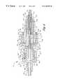
- FIG. 4is a cross-sectional view of the tubing connector of FIG. 3 taken along line 4 — 4 .
- FIG. 5is a cross-sectional view of an alternate embodiment of a tubing connector of the present invention.
- the tubing connector 10comprises a body 12 , a tubular member 14 , a compression member 15 , and a cap 16 .
- the body 12is an integral structure comprising a central cylinder 18 , a flange 20 , a first shroud 22 , and a second shroud 24 .
- the flange 20has a circular configuration and is aligned substantially perpendicular to the longitudinal axis of the tubing connector 10 .
- the first shroud 22extends longitudinally from the outer periphery of the flange 20 in a first direction which is substantially parallel to the longitudinal axis of the tubing connector and perpendicular to the planar orientation of the flange 20 .
- the first shroud 22is equidistantly aligned about the longitudinal axis of the body 12 , rendering the first shroud 22 concentric with the body 12 .
- the central cylinder 18likewise extends longitudinally in the first direction, but from the center of the flange 20 along the longitudinal axis of the body 12 concentric with the body 12 .
- the outside diameter of the central cylinder 18is substantially less than the inside diameter of the first shroud 22 , thereby forming an annulus 26 between the inside wall 28 of the first shroud 22 and the outside wall 30 of the central cylinder 18 .
- the central cylinder 18is slightly shorter in length than the first shroud 22 so that the central cylinder 18 does not substantially extend past the outside edge 32 of the first shroud 22 .
- the inside wall 28 of the first shroud 22is threaded with a continuous female thread 34 which serves as a first cooperative coupling element.
- the outside wall 36 of the first shroud 22has a series of longitudinal ridges 38 formed thereon to facilitate manual gripping and rotating of the body 12 .
- a continuous central bore 40extends longitudinally through the body 12 along the longitudinal axis of the body 12 concentric with the body 12 .
- the central bore 40has a widened section 41 which is substantially enclosed by the second shroud 24 .
- the widened section 41is followed in series, moving in the first direction, by an intermediately positioned tapered section 42 having a hemispherical or frustaconical configuration which extends to the flange 20 , and a uniformly narrowed section 43 which is enclosed by the central cylinder 18 .
- the wall thickness of the central cylinder 18 surrounding the narrowed section 43is substantially greater than the wall thickness of the first shroud 22 .
- the second shroud 24extends longitudinally from the flange 20 in a second direction which is substantially opposite the first direction.
- the outside diameter of the second shroud 24approximates the outside diameter of the central cylinder 18 .
- the cross-section of the second shroud 24is substantially less than that of the first shroud 22 , while the length and wall thickness of the second shroud 24 are similar to the length and wall thickness of the first shroud 22 .
- the second shroud 24has a more narrow tube-like configuration than the first shroud 22 .
- the second shroud 24like the first shroud 22 , is equidistantly aligned about the longitudinal axis of the body 12 and, thereby, concentric with the body 12 .
- the widened section 41 of the central bore 40defines the interior of the second shroud 24 .
- the outside edge 46 of the second shroud 24has a pair of radially-extending tabs 48 formed thereon which serve as a coupling element to enable coupling of the body 12 with an adjoining member.
- the body 12is integrally formed from a strong, durable, rigid plastic, such as a molded polycarbonate or rigid PVC, or some other synthetic nonmetallic material.
- the material of the body 12is substantially rigid and inelastic, being highly resistant to elastic deformation and failure.
- the tubular member 14has a tube configuration with the characteristics of a straight, uniform, thin-walled, continuously open cannula having open first and second ends 50 and 51 , respectively.
- the tubular member 14is extremely strong, durable and rigid throughout its length, preferably formed from a material having at least equal or greater strength, durability and rigidity than the non-metallic material of the body 12 .
- a preferred tubular member 14is formed from a high-strength metal, such as stainless steel. As such the material of the tubular member 14 is likewise substantially rigid and inelastic, being at least equally or more resistant to elastic deformation and failure than the material of the body 12 .
- the tubular member 14is fixably positioned within the central bore 40 using an elastic plug 52 formed from a pliant, elastically-deformable material such as a relatively pliant elastomer or silicon rubber.
- the plug 52preferably has the configuration of an O-ring or short tubing section provided with a central opening 53 .
- the tubular member 14is fixably positioned in the central bore 40 by inserting the second end 51 of the tubular member 14 into the central opening 53 of the plug 52 .
- the first end 50 of the tubular member 14is then slid through the central bore 40 in the first direction until the plug 52 reaches the tapered section 42 .
- the plug 52is forcibly pressed into the tapered section 42 compressing the plug 52 against the wall of the tapered section 42 and deforming the outer configuration of the plug 52 to resemble that of the tapered section 42 .
- the compression force of the plug 52 against the wall of the tapered section 42renders the plug 52 , and the tubular member 14 positioned therein, essentially immobile and anchored within the central bore 40 .
- the tubular member 14may alternatively be secured within the central bore 40 by a bonder, such as a glue or adhesive, and more particularly a UV or epoxy adhesive, applied to the wall of the narrowed section 43 .
- a bondersuch as a glue or adhesive, and more particularly a UV or epoxy adhesive
- the tubular member 14may be secured within the central bore 40 by welding the tubular member 14 to the wall of the narrowed section 43 , by insert molding the tubular member 14 in the narrowed section 43 , or by press fitting the tubular member 14 into the narrowed section 43 .
- the tapered section 42 of the central bore 40may be omitted, with the central bore 40 transitioning directly from the widened section 41 to the narrowed section 43 .
- the tubular member 14is substantially longer than the combined length of the tapered and narrowed sections 42 , 43 of the central bore 40 .
- a body portion 54 of the tubular member 14 which is proximal to the open second end 51resides in the entirety of the combined length of the tapered and narrowed sections 42 , 43 .
- An extension portion 55 of the tubular member 14 which is proximal to the open first end 50extends out of the central bore 40 in the first direction away from the body 12 such that the first end 50 has substantial clearance from the central cylinder 18 and the first shroud 22 .
- the extension portion 55preferably has a length equal to or somewhat greater than the length of the compression member 15 .
- the open second end 51does not extend in the second direction from the tapered section 42 into the widened section 41 .
- the second end 51may extend if desired into the widened section 41 , although typically to a lesser degree than the first end 50 extends from the narrowed section 43 in the first direction.
- the second end 51is substantially enclosed by the second shroud 24 .
- the widened section 41 and tubular member 14in series, provide a continuous open passageway through the body 12 when the body portion 54 of the tubular member 14 is fixably positioned in the central bore 40 .
- the cap 16is an integral structure preferably integrally formed from a strong, durable, rigid plastic which is substantially inelastic, such as the material used to form the body 12 .
- the cap 16has a first end 56 with an opening 57 encircled by an outside wall 58 , wherein the diameter of the outside wall 58 at the opening 57 is slightly less than the diameter of the inside wall 28 of the first shroud 22 .
- the outside wall 58is threaded with a continuous male thread 60 which serves as a second cooperative coupling element to be fastenably received by the continuous female thread 34 on the inside wall 28 of the first shroud 22 .
- the outside wall 58When the outside wall 58 is in threadably fastened engagement with the inside wall 28 , the outside wall 58 is received by the annulus 26 and the first end 50 of the tubular member 14 extends through the opening 57 of the cap 16 .
- a second opposite end 62 of the cap 16tapers to an orifice 64 centrally aligned along the longitudinal axis of the cap 16 .
- the diameter of the orifice 64is sized larger than the outside diameter of the tubular member 14 to receive the first end 50 of the tubular member 14 therein.
- the compression member 15is shown fifted as an insert into the interior of the cap 16 against the inside wall 66 proximal to the second end 62 .
- the compression member 15is preferably secured in the interior of the cap 16 by compression fitting or other means such as bonding or the like.
- the compression member 15is formed from a substantially non-rigid, pliant, elastically-deformable material, i.e., substantially more elastically deformable than the material of the body 12 , tubular member 14 or cap 16 when subjected to the level of compressive forces experienced during use of the tubing connector 10 .
- Latexis an exemplary elastic material from which the compression member 15 may be fabricated, although the present invention is not limited to a specific elastically-deformable material.
- the compression member 15may be formed from a substantially rigid inelastic material and provided with mechanical means (not shown) which enable elastic deformation of the compression member 15 , such as expansion/contraction slots, grooves or other mechanical means within the purview of the skilled artisan.
- the compression member 15is readily susceptible to physical elastic deformation whereby the compression member 15 elastically changes shape without a substantial change in volume when compressed between the body 12 and the cap 16 in a manner described below.
- the compression member 15has a central bore 68 therethrough which is in serial alignment with the orifice 64 .
- the central bore 68has a diameter substantially the same as the orifice 64 , i.e., greater than the outside diameter of the tubular member 14 , to likewise receive the first end 50 of the tubular member 14 therethrough.
- the outside wall 58has a pair of tabs 70 formed thereon proximal to the second end 62 to facilitate manual gripping and rotating of the cap 16 .
- the tubing connector 10is designed for use in cooperation with an associated tube 72 and an adjoining member 74 .
- the tube 72 shown hereinis a clear, flexible, plastic medical catheter 72 .
- the present medical catheter 72is typically a 10 to 20 gauge tubing formed from a material such as nylon or polyurethane.
- a preferred catheter 72is a 16 gauge tubing having a relatively small outside diameter of about 0.057 inches, a relatively small inside diameter of about 0.036 inches and a durameter flexibility of about 65D.
- the adjoining member 74is shown herein, by way of example, to be a substantially uniform, transparent or translucent, flexible, plastic extension tube.
- the extension tube 74is a relatively large vinyl tubing of the type termed in the art as “microbore tubing” which has an outside diameter of about 0.094 inches.
- the extension tube 74has a relatively large flow cross-section which enables the rapid displacement of relatively large volumes of liquids through the extension tube 74 .
- the adjoining membercan alternately be other constructs such as the outlet of a treatment fluid reservoir or a fluid delivery device (not shown).
- the tubing connector 10is shown specifically designed for coupling the external end 76 of the catheter 72 with an end 77 of the extension tube 74 by releasably mating the second shroud 24 with a connector 78 mounted on the end 77 .
- the inside diameter of the orifice 64 and the diameter of the bore 68are sized larger than the outside diameter of the catheter 72 .
- the orifice 64 and bore 68can slidably receive the catheter 72 therethrough.
- the outside diameter of the first end 50 of the tubular member 14is sized smaller than the inside diameter of the catheter 72 so that the catheter 72 slidably fits over the first end 50 .
- the connector 78is an integral structure preferably integrally formed from a durable, rigid plastic, such as the material used to form the body 12 and the cap 16 .
- the connector 78comprises a central cylinder 80 , a flange 82 , a shroud 84 , and a tubing retainer 86 .
- the central cylinder 80 , flange 82 and shroud 84are configured in a substantially similar manner to the corresponding components 18 , 20 , 22 of the tubing connector 10 .
- the central cylinder 80 and the shroud 84form an annulus 88 between them. However, the central cylinder 80 is somewhat longer in length than the shroud 84 so that the central cylinder 80 extends past the annulus 88 and the outside edge 90 of the shroud 84 .
- the inside wall 92 of the shroud 84is threaded with a continuous thread 94 which serves as a coupling element.
- the diameter of the inside wall 90 of the shroud 84is slightly greater than the diameter of the outside edge 32 of the second shroud 24 of the body 12 so that the second shroud 24 can be received within the annulus 88 of the shroud 84 when the tabs 48 are in threadably fastened engagement with the thread 94 .
- the second shroud 24functions in the manner of a female Luer lock fitting to receive the central cylinder 80 and the shroud 84 functions in the manner of a male Luer lock fitting.
- the outside wall 96 of the shroud 84has a series of longitudinal ridges 98 formed thereon to facilitate manual gripping and rotating of the connector 78 .
- a continuous narrow central bore 100having a diameter substantially similar to the diameter of the central bore 40 , extends longitudinally through the central cylinder 80 and the flange 82 along the longitudinal axis of the connector 78 .
- the tubing retainer 86extends longitudinally from the flange 82 in a direction opposite the shroud 84 .
- the tubing retainer 86is equidistantly aligned about the longitudinal axis of the connector 78 concentric with the central cylinder 80 .
- the outside wall 102 of the tubing retainer 86has a pair of tabs 104 formed thereon to facilitate manual gripping and rotating of the connector 78 .
- the interior of the tubing retainer 86 and the central bore 100provide a continuous open passageway through the connector 78 .
- the inside diameter of the tubing retainer 86is somewhat less than the outside diameter of the end 77 of the extension tube 74 to receive the extension tube 74 therein.
- the extension tube 74is preferably fixably anchored within the tubing retainer 86 by welding, an adhesive, or other fastening means.
- the practitionerassembles the tubing connector 10 in association with the catheter 72 and extension tube 74 in accordance with the following procedure.
- the catheter 72is initially maintained free from attachment to the tubing connector 10 or any other components as shown in FIG. 1 .
- An internal end 106 of the catheter 72is placed internally beneath the skin of a patient at or near a treatment site (not shown) preferably by means of an introducer needle and insertion catheter (not shown) in accordance with a technique described in the commonly owned copending U.S. patent application Ser. No. 09/334,856 filed Jun. 16, 1999, entitled “Patient-Controlled Medication Delivery System”, which is incorporated herein by reference.
- the internal end 106is fixed in the treatment site by securing an adjacent exposed segment of the catheter 72 to the skin of the patient with a strip of tape or other securing means.
- the external end 76 of the catheter 72is manually threaded from the second direction into the orifice 64 in the second end 62 of the cap 16 , through the bore 68 , and out the opening 57 in the first end 56 with several centimeters of the catheter 72 extending in the second direction from the opening 57 .
- the external end 76is manually fitted over the first end 50 of the tubular member 14 and the external end 76 is urged in the second direction over the entire length of the extension portion 55 until the external end 76 of the catheter 72 engages the central cylinder 18 as shown in FIG. 2 .
- the cap 16is slid along the catheter 72 in the second direction toward the body 12 until the thread 60 engages the thread 34 .
- the threads 34 , 60are screwed together positioning the first end 50 of the tubular member 14 in the orifice 64 and bringing the central cylinder 18 into engagement with the compression member 15 .
- the first end 50 of the tubular member 14preferably does not extend in the first direction beyond the orifice 64 to avoid flexing the catheter 72 over the first end 50 and occluding the catheter 72 during use.
- the threads 34 , 60are tightened to complete assembly of the tubing connector 10 , the central cylinder 18 engages and elastically deforms the compression member 15 which is countered by the inside wall of the cap 16 .
- the compression member 15By compressing the compression member 15 against the length of the catheter 72 which covers the extension portion 55 , the compression member 15 tightly retains the catheter 72 in the tubing connector 10 while the tubular member 14 prevents the compression member 15 from collapsing the catheter 72 within the tubing connector 10 . Accordingly, the catheter 72 and tubular member 14 define an occlusion-resistant fluid pathway from the treatment site through the assembled tubing connector 10 .
- the shroud 84 of the connector 78is placed around the outside edge 46 of the second shroud 24 until the tabs 48 engage the thread 94 of the shroud 84 .
- the shroud 84is tightened down onto the second shroud 24 by rotating them in opposite directions providing fluid-tight connective engagement between the body 12 and the connector 78 as shown in FIG. 3 .
- the opposite end (not shown) of the extension tube 74may then be connected to a remote device (not shown) such as an infusion pump described in U.S. patent application Ser. No. 09/334,856.
- the tubing connector 10 of the present inventionenables the practitioner to employ a catheter 72 having both a relatively small diameter and a relatively high degree of flexibility while securely retaining the catheter 72 and coupling the catheter 72 with an adjoining member 74 .
- the tubing connector 10and in particular the tubular member 14 and compression member 15 , allow the application of a higher compressive force to the catheter 72 to more effectively retain the catheter 72 in the tubing connector 10 while at the same time preventing the higher compressive force from substantially occluding, collapsing or otherwise restricting the catheter 72 .
- a tubing connectormay be constructed which is substantially similar to the tubing connector 10 , but wherein the tubular member 14 is not anchored to the body 12 of the tubing connector.
- neither the plug 52 nor any bondersare utilized.
- the external end 76 of the catheter 72is manually fitted over the first end 50 of the tubular member 14 while the tubular member 14 is substantially free from the body 12 .
- the external end 76is urged over the entirety of the tubular member 14 until the external end 76 is flush with the second end 51 .
- the tubular member 14 and external end 76are then manually threaded through the cap 16 .
- the order of assemblyis reversed, wherein the external end 76 is threaded through the cap 16 first and then the tubular member 14 is fitted in the external end 76 .
- the external end 76 having the tubular member 14 fitted thereinis positioned in the bores 40 , 68 , which are sized to receive both the external end 76 and tubular member 14 .
- the cap 16is secured to the body 12 in substantially the same manner as described above with respect to the previous embodiment.
- the compressive force of the central cylinder 18 against the compression member 15retains the tubular member 14 and external end 76 in the bores 40 , 68 as long as the cap 16 remains secured to the body 12 .
- connective engagement of the body 12 with the connector 78is described above by fitting the second shroud 24 of the body 12 into the shroud 84 of the connector 78 .
- the configuration of the shrouds 24 and 84can be reversed so that the shroud of the connector fits into the second shroud of the body.
- connective engagement of the body 12 with the cap 16is described above by screwing the first end 56 of the cap 16 into the first shroud 22 of the body 12 .
- the configuration of the first end 56 and first shroud 22can be reversed so that the first shroud of the body screws into the first end of the cap.
- the body 12is reconfigured without the tabs 48 on the second shroud 24 .
- the second shroud 24may be configured as a barbed tube fitting to connect the extension tube 74 or other adjoining member directly to the body 12 and obviate the connector 78 .
- the second shroud 24may be configured as a fitting to glue or otherwise bond the extension tube 74 or other adjoining member directly to the body 12 and likewise obviate the connector 78 .
- the second shroud 24may be integrally formed with an adjoining member so that the body and adjoining member are a single integrated structure.
- the body 12could be integrally formed on the outlet of a syringe or infusion pump.
- the second shroud 24may be retained as is on the body 12 , substantially shortened, or completely omitted from the body 12 , obviating the widened section 41 of the bore 40 and repositioning the tapered section 42 in the central cylinder 18 .
- FIG. 5another alternate embodiment of the tubing connector is shown and generally designated 200 .
- the tubing connector 200has a number of components substantially identical to those of FIG. 4 which are identified in FIG. 5 by the same reference characters as FIG. 4 .
- the tubing connector 200differs from the tubing connector 10 primarily in the omission of the first shroud 22 from the body 202 .
- a male thread 204is provided on the outside wall 30 of the central cylinder 18 and a corresponding female thread 206 is provided on the inside wall 66 of the cap 16 proximal to the first end 56 .
- the tubing connector 200is assembled by screwing the male thread 204 of the central cylinder 18 into the female thread 206 of the cap 16 and compressing the compression member 15 to retain the external end 76 of the catheter 72 in substantially the same manner as described above with respect to the tubing connector 10 .
Landscapes
- Engineering & Computer Science (AREA)
- General Engineering & Computer Science (AREA)
- Health & Medical Sciences (AREA)
- Mechanical Engineering (AREA)
- Heart & Thoracic Surgery (AREA)
- Anesthesiology (AREA)
- Pulmonology (AREA)
- Biomedical Technology (AREA)
- Hematology (AREA)
- Life Sciences & Earth Sciences (AREA)
- Animal Behavior & Ethology (AREA)
- General Health & Medical Sciences (AREA)
- Public Health (AREA)
- Veterinary Medicine (AREA)
- Infusion, Injection, And Reservoir Apparatuses (AREA)
Abstract
Description
Claims (23)
Priority Applications (1)
| Application Number | Priority Date | Filing Date | Title |
|---|---|---|---|
| US09/374,703US6260890B1 (en) | 1999-08-12 | 1999-08-12 | Tubing connector |
Applications Claiming Priority (1)
| Application Number | Priority Date | Filing Date | Title |
|---|---|---|---|
| US09/374,703US6260890B1 (en) | 1999-08-12 | 1999-08-12 | Tubing connector |
Publications (1)
| Publication Number | Publication Date |
|---|---|
| US6260890B1true US6260890B1 (en) | 2001-07-17 |
Family
ID=23477877
Family Applications (1)
| Application Number | Title | Priority Date | Filing Date |
|---|---|---|---|
| US09/374,703Expired - Fee RelatedUS6260890B1 (en) | 1999-08-12 | 1999-08-12 | Tubing connector |
Country Status (1)
| Country | Link |
|---|---|
| US (1) | US6260890B1 (en) |
Cited By (48)
| Publication number | Priority date | Publication date | Assignee | Title |
|---|---|---|---|---|
| US20030151256A1 (en)* | 2002-02-08 | 2003-08-14 | Industrie Borla Spa | Male luer lock connector for medical fluid lines |
| US6673059B2 (en)* | 2001-02-16 | 2004-01-06 | Industrie Borla Spa | Male luer-lock connector for medical fluid lines |
| US20040155457A1 (en)* | 2003-02-12 | 2004-08-12 | Maersk Medical A/S | Connecting element comprising a first body and a method for injection moulding a connecting element |
| US20040265091A1 (en)* | 2003-06-30 | 2004-12-30 | Cheung Kwun-Wing W. | Universal bulkhead fitting |
| US20050143797A1 (en)* | 2003-07-18 | 2005-06-30 | Thermotek, Inc. | Compression sequenced thermal therapy system |
| US20050142945A1 (en)* | 2003-02-12 | 2005-06-30 | Unomedical A/S | Connecting element comprising a first body and a method for injection moulding a connecting element |
| USD517209S1 (en) | 2004-03-26 | 2006-03-14 | Cook Incorporated | Luer fitting connector |
| US7044936B2 (en) | 2002-08-21 | 2006-05-16 | Arrow International Inc. | Catheter connector with pivot lever spring latch |
| US20070225684A1 (en)* | 2006-03-24 | 2007-09-27 | Medical Components, Inc. | Luer connector assembly with clamping sleeve and method of use |
| US20080214990A1 (en)* | 2007-03-02 | 2008-09-04 | Smith & Nephew, Inc. | Fluid Conduit Connection |
| US20080284167A1 (en)* | 2007-05-18 | 2008-11-20 | Eugene Lim | Low-volume fittings |
| US7520489B2 (en) | 2003-06-17 | 2009-04-21 | Filtertek Inc. | Fluid handling device and method of making same |
| US7804686B2 (en) | 2004-08-12 | 2010-09-28 | Thermotek, Inc. | Thermal control system for rack mounting |
| US20100318039A1 (en)* | 2007-12-20 | 2010-12-16 | Smith & Nephew Plc | Connectors |
| US20100327577A1 (en)* | 2009-06-25 | 2010-12-30 | Herbert Funke | Fitting connection |
| US20110006519A1 (en)* | 2008-02-15 | 2011-01-13 | Erwin Weh | Screw Connection |
| US20110041427A1 (en)* | 2008-02-15 | 2011-02-24 | Agc Glass Europe | Glazing panel |
| US20110060317A1 (en)* | 2009-09-04 | 2011-03-10 | Froejd Goeran | Catheter with customizable connector |
| US7909861B2 (en) | 2005-10-14 | 2011-03-22 | Thermotek, Inc. | Critical care thermal therapy method and system |
| US8006367B1 (en)* | 2007-10-24 | 2011-08-30 | Best John W | Fitting to secure tubing within a CPI port |
| US8100956B2 (en) | 2006-05-09 | 2012-01-24 | Thermotek, Inc. | Method of and system for thermally augmented wound care oxygenation |
| US8128672B2 (en) | 2006-05-09 | 2012-03-06 | Thermotek, Inc. | Wound care method and system with one or both of vacuum-light therapy and thermally augmented oxygenation |
| USD662212S1 (en) | 2007-04-10 | 2012-06-19 | Thermotek, Inc. | Butterfly wrap |
| USD679023S1 (en) | 2004-07-19 | 2013-03-26 | Thermotek, Inc. | Foot wrap |
| US8574278B2 (en) | 2006-05-09 | 2013-11-05 | Thermotek, Inc. | Wound care method and system with one or both of vacuum-light therapy and thermally augmented oxygenation |
| US20130310807A1 (en)* | 1998-10-29 | 2013-11-21 | Medtronic Minimed, Inc. | Medication reservoir |
| US8731638B2 (en) | 2009-07-20 | 2014-05-20 | Optiscan Biomedical Corporation | Adjustable connector and dead space reduction |
| US8731639B2 (en) | 2009-07-20 | 2014-05-20 | Optiscan Biomedical Corporation | Adjustable connector, improved fluid flow and reduced clotting risk |
| US8758419B1 (en) | 2008-01-31 | 2014-06-24 | Thermotek, Inc. | Contact cooler for skin cooling applications |
| US8778005B2 (en) | 2003-07-18 | 2014-07-15 | Thermotek, Inc. | Method and system for thermal and compression therapy relative to the prevention of deep vein thrombosis |
| WO2015087881A1 (en)* | 2013-12-11 | 2015-06-18 | 株式会社ジェイ・エム・エス | Male connector |
| US9119705B2 (en) | 1998-06-08 | 2015-09-01 | Thermotek, Inc. | Method and system for thermal and compression therapy relative to the prevention of deep vein thrombosis |
| US9615967B2 (en) | 2010-12-30 | 2017-04-11 | Coolsystems, Inc. | Reinforced therapeutic wrap and method |
| US9669233B2 (en) | 2013-11-11 | 2017-06-06 | Thermotek, Inc. | Method and system for wound care |
| US9675751B2 (en) | 2010-07-31 | 2017-06-13 | Becton, Dickinson And Company | Infusion reservoir with push-on connector features and/or attachments therefor |
| USD796034S1 (en)* | 2015-04-13 | 2017-08-29 | Medela Holding Ag | Tubing connector for a breastmilk system |
| US9943437B2 (en) | 2009-10-22 | 2018-04-17 | Coolsystems, Inc. | Temperature and flow control methods in a thermal therapy device |
| US9980844B2 (en) | 2007-02-13 | 2018-05-29 | Coolsystems, Inc. | Flexible joint wrap |
| US10016583B2 (en) | 2013-03-11 | 2018-07-10 | Thermotek, Inc. | Wound care and infusion method and system utilizing a thermally-treated therapeutic agent |
| US10149927B2 (en) | 2012-04-24 | 2018-12-11 | Thermotek, Inc. | Method and system for therapeutic use of ultra-violet light |
| US10300180B1 (en) | 2013-03-11 | 2019-05-28 | Thermotek, Inc. | Wound care and infusion method and system utilizing a therapeutic agent |
| US10456320B2 (en) | 2013-10-01 | 2019-10-29 | Coolsystems, Inc. | Hand and foot wraps |
| US10463565B2 (en) | 2011-06-17 | 2019-11-05 | Coolsystems, Inc. | Adjustable patient therapy device |
| US10512587B2 (en) | 2011-07-27 | 2019-12-24 | Thermotek, Inc. | Method and apparatus for scalp thermal treatment |
| US10765785B2 (en) | 2004-07-19 | 2020-09-08 | Thermotek, Inc. | Wound care and infusion method and system utilizing a therapeutic agent |
| US10859295B2 (en) | 2016-04-13 | 2020-12-08 | ZeoThermal Technologies, LLC | Cooling and heating platform |
| US11013635B2 (en) | 2004-05-17 | 2021-05-25 | Coolsystems, Inc. | Modular apparatus for therapy of an animate body |
| US11672693B2 (en) | 2014-08-05 | 2023-06-13 | Avent, Inc. | Integrated multisectional heat exchanger |
Citations (13)
| Publication number | Priority date | Publication date | Assignee | Title |
|---|---|---|---|---|
| US3496937A (en)* | 1967-05-18 | 1970-02-24 | John E Balson | Hypodermic syringe |
| US4187848A (en)* | 1977-07-18 | 1980-02-12 | The Kendall Company | Adapter assembly |
| US4346703A (en)* | 1979-01-23 | 1982-08-31 | Baxter Travenol Laboratories, Inc. | Solution container for continuous ambulatory peritoneal dialysis |
| US4360024A (en)* | 1977-10-07 | 1982-11-23 | H. G. Wallace Limited | Catheter with liquid flow control means |
| US4508367A (en)* | 1979-01-09 | 1985-04-02 | Oreopoulos Dimitrios G | Connector |
| US4512766A (en)* | 1982-12-08 | 1985-04-23 | Whitman Medical Corporation | Catheter valve |
| US4690437A (en)* | 1986-02-27 | 1987-09-01 | Alltech Associates, Inc. | Low pressure fitting |
| US5334188A (en)* | 1987-12-07 | 1994-08-02 | Nissho Corporation | Connector with injection site |
| US5669637A (en)* | 1996-05-29 | 1997-09-23 | Optimize Technologies, Inc. | Miniature fitting assembly for micro-tubing |
| US5766203A (en)* | 1995-07-20 | 1998-06-16 | Intelliwire, Inc. | Sheath with expandable distal extremity and balloon catheters and stents for use therewith and method |
| US5908405A (en)* | 1994-10-28 | 1999-06-01 | Intella Interventional Systems, Inc. | Low profile balloon-on-a-wire catheter with shapeable and/or deflectable tip and method |
| US5951060A (en)* | 1996-03-22 | 1999-09-14 | Smc Kabushiki Kaisha | Pipe joint |
| US5984373A (en)* | 1998-03-12 | 1999-11-16 | Elcam Plastic Kibbutz Bar-Am | Luer connector |
- 1999
- 1999-08-12USUS09/374,703patent/US6260890B1/ennot_activeExpired - Fee Related
Patent Citations (13)
| Publication number | Priority date | Publication date | Assignee | Title |
|---|---|---|---|---|
| US3496937A (en)* | 1967-05-18 | 1970-02-24 | John E Balson | Hypodermic syringe |
| US4187848A (en)* | 1977-07-18 | 1980-02-12 | The Kendall Company | Adapter assembly |
| US4360024A (en)* | 1977-10-07 | 1982-11-23 | H. G. Wallace Limited | Catheter with liquid flow control means |
| US4508367A (en)* | 1979-01-09 | 1985-04-02 | Oreopoulos Dimitrios G | Connector |
| US4346703A (en)* | 1979-01-23 | 1982-08-31 | Baxter Travenol Laboratories, Inc. | Solution container for continuous ambulatory peritoneal dialysis |
| US4512766A (en)* | 1982-12-08 | 1985-04-23 | Whitman Medical Corporation | Catheter valve |
| US4690437A (en)* | 1986-02-27 | 1987-09-01 | Alltech Associates, Inc. | Low pressure fitting |
| US5334188A (en)* | 1987-12-07 | 1994-08-02 | Nissho Corporation | Connector with injection site |
| US5908405A (en)* | 1994-10-28 | 1999-06-01 | Intella Interventional Systems, Inc. | Low profile balloon-on-a-wire catheter with shapeable and/or deflectable tip and method |
| US5766203A (en)* | 1995-07-20 | 1998-06-16 | Intelliwire, Inc. | Sheath with expandable distal extremity and balloon catheters and stents for use therewith and method |
| US5951060A (en)* | 1996-03-22 | 1999-09-14 | Smc Kabushiki Kaisha | Pipe joint |
| US5669637A (en)* | 1996-05-29 | 1997-09-23 | Optimize Technologies, Inc. | Miniature fitting assembly for micro-tubing |
| US5984373A (en)* | 1998-03-12 | 1999-11-16 | Elcam Plastic Kibbutz Bar-Am | Luer connector |
Non-Patent Citations (1)
| Title |
|---|
| Drawing No. 80354: Pediatric Touchy Borst Adapter, Qosina Corp., Feb. 19, 1999.* |
Cited By (87)
| Publication number | Priority date | Publication date | Assignee | Title |
|---|---|---|---|---|
| US9877864B2 (en) | 1998-06-08 | 2018-01-30 | Thermotek, Inc. | Compression sequenced thermal therapy system |
| US9119705B2 (en) | 1998-06-08 | 2015-09-01 | Thermotek, Inc. | Method and system for thermal and compression therapy relative to the prevention of deep vein thrombosis |
| US10507131B2 (en) | 1998-06-08 | 2019-12-17 | Thermotek, Inc. | Method and system for thermal and compression therapy relative to the prevention of deep vein thrombosis |
| US9433525B2 (en) | 1998-06-08 | 2016-09-06 | Thermotek, Inc. | Compression sequenced thermal therapy system |
| US9180041B2 (en) | 1998-06-08 | 2015-11-10 | Thermotek, Inc. | Compression sequenced thermal therapy system |
| US20130310807A1 (en)* | 1998-10-29 | 2013-11-21 | Medtronic Minimed, Inc. | Medication reservoir |
| US6673059B2 (en)* | 2001-02-16 | 2004-01-06 | Industrie Borla Spa | Male luer-lock connector for medical fluid lines |
| US6893056B2 (en)* | 2002-02-08 | 2005-05-17 | Industrie Borla Spa | Male luer lock connector for medical fluid lines |
| US20030151256A1 (en)* | 2002-02-08 | 2003-08-14 | Industrie Borla Spa | Male luer lock connector for medical fluid lines |
| US7044936B2 (en) | 2002-08-21 | 2006-05-16 | Arrow International Inc. | Catheter connector with pivot lever spring latch |
| US20050142945A1 (en)* | 2003-02-12 | 2005-06-30 | Unomedical A/S | Connecting element comprising a first body and a method for injection moulding a connecting element |
| US7455325B2 (en) | 2003-02-12 | 2008-11-25 | Unomedical A/S | Connecting element comprising a first body and a method for injection moulding a connecting element |
| US20040155457A1 (en)* | 2003-02-12 | 2004-08-12 | Maersk Medical A/S | Connecting element comprising a first body and a method for injection moulding a connecting element |
| US7520489B2 (en) | 2003-06-17 | 2009-04-21 | Filtertek Inc. | Fluid handling device and method of making same |
| US8038123B2 (en)* | 2003-06-17 | 2011-10-18 | Filtertek Inc. | Fluid handling device and method of making same |
| US20040265091A1 (en)* | 2003-06-30 | 2004-12-30 | Cheung Kwun-Wing W. | Universal bulkhead fitting |
| US8778005B2 (en) | 2003-07-18 | 2014-07-15 | Thermotek, Inc. | Method and system for thermal and compression therapy relative to the prevention of deep vein thrombosis |
| US9192539B2 (en) | 2003-07-18 | 2015-11-24 | Thermotek, Inc. | Method and system for thermal and compression therapy relative to the prevention of deep vein thrombosis |
| US10507140B2 (en) | 2003-07-18 | 2019-12-17 | Thermotek, Inc. | Wound care method and system with one or both of vacuum-light therapy and thermally augmented oxygenation |
| US8753383B2 (en) | 2003-07-18 | 2014-06-17 | Thermotek, Inc. | Compression sequenced thermal therapy system |
| US9616210B2 (en) | 2003-07-18 | 2017-04-11 | Thermotek, Inc. | Wound care method and system with one or both of vacuum-light therapy and thermally augmented oxygenation |
| US20050143797A1 (en)* | 2003-07-18 | 2005-06-30 | Thermotek, Inc. | Compression sequenced thermal therapy system |
| US8425580B2 (en) | 2003-07-18 | 2013-04-23 | Thermotek, Inc. | Method of and system for thermally augmented wound care oxygenation |
| USD517209S1 (en) | 2004-03-26 | 2006-03-14 | Cook Incorporated | Luer fitting connector |
| US11013635B2 (en) | 2004-05-17 | 2021-05-25 | Coolsystems, Inc. | Modular apparatus for therapy of an animate body |
| US8940034B2 (en) | 2004-07-19 | 2015-01-27 | Thermotek, Inc. | Wound care method and system with one or both of vacuum-light therapy and thermally augmented oxygenation |
| USD679023S1 (en) | 2004-07-19 | 2013-03-26 | Thermotek, Inc. | Foot wrap |
| US10765785B2 (en) | 2004-07-19 | 2020-09-08 | Thermotek, Inc. | Wound care and infusion method and system utilizing a therapeutic agent |
| US7804686B2 (en) | 2004-08-12 | 2010-09-28 | Thermotek, Inc. | Thermal control system for rack mounting |
| US8248798B2 (en) | 2004-08-12 | 2012-08-21 | Thermotek, Inc. | Thermal control system for rack mounting |
| US7909861B2 (en) | 2005-10-14 | 2011-03-22 | Thermotek, Inc. | Critical care thermal therapy method and system |
| US8636719B2 (en)* | 2006-03-24 | 2014-01-28 | Medical Components, Inc. | Luer connector assembly with clamping sleeve and method of use |
| US20070225684A1 (en)* | 2006-03-24 | 2007-09-27 | Medical Components, Inc. | Luer connector assembly with clamping sleeve and method of use |
| US8574278B2 (en) | 2006-05-09 | 2013-11-05 | Thermotek, Inc. | Wound care method and system with one or both of vacuum-light therapy and thermally augmented oxygenation |
| US8142486B2 (en) | 2006-05-09 | 2012-03-27 | Thermotek, Inc. | Wound care method and system with one or both of vacuum-light therapy and thermally augmented oxygenation |
| US10507311B2 (en) | 2006-05-09 | 2019-12-17 | Thermotek, Inc. | Wound care method and system with one or both of vacuum-light therapy and thermally augmented oxygenation |
| US8128672B2 (en) | 2006-05-09 | 2012-03-06 | Thermotek, Inc. | Wound care method and system with one or both of vacuum-light therapy and thermally augmented oxygenation |
| US8632576B2 (en) | 2006-05-09 | 2014-01-21 | Thermotek, Inc. | Wound care method and system with one or both of vacuum-light therapy and thermally augmented oxygenation |
| US9950148B2 (en) | 2006-05-09 | 2018-04-24 | Thermotek, Inc. | Wound care method and system with one or both of vacuum-light therapy and thermally augmented oxygenation |
| US8100956B2 (en) | 2006-05-09 | 2012-01-24 | Thermotek, Inc. | Method of and system for thermally augmented wound care oxygenation |
| US9980844B2 (en) | 2007-02-13 | 2018-05-29 | Coolsystems, Inc. | Flexible joint wrap |
| US7926856B2 (en)* | 2007-03-02 | 2011-04-19 | Smith & Nephew, Inc. | Fluid conduit connection |
| US8915903B2 (en) | 2007-03-02 | 2014-12-23 | Smith & Nephew, Inc. | Fluid conduit connection |
| US20110196314A1 (en)* | 2007-03-02 | 2011-08-11 | Smith & Nephew, Inc. | Fluid conduit connection |
| US20080214990A1 (en)* | 2007-03-02 | 2008-09-04 | Smith & Nephew, Inc. | Fluid Conduit Connection |
| USD683042S1 (en) | 2007-04-10 | 2013-05-21 | Thermotek, Inc. | Calf wrap |
| USD662214S1 (en) | 2007-04-10 | 2012-06-19 | Thermotek, Inc. | Circumferential leg wrap |
| USD662212S1 (en) | 2007-04-10 | 2012-06-19 | Thermotek, Inc. | Butterfly wrap |
| USD664260S1 (en) | 2007-04-10 | 2012-07-24 | Thermotek, Inc. | Calf wrap |
| USD662213S1 (en) | 2007-04-10 | 2012-06-19 | Thermotek, Inc. | Knee wrap |
| US20080284167A1 (en)* | 2007-05-18 | 2008-11-20 | Eugene Lim | Low-volume fittings |
| US8006367B1 (en)* | 2007-10-24 | 2011-08-30 | Best John W | Fitting to secure tubing within a CPI port |
| US20100318039A1 (en)* | 2007-12-20 | 2010-12-16 | Smith & Nephew Plc | Connectors |
| US8758419B1 (en) | 2008-01-31 | 2014-06-24 | Thermotek, Inc. | Contact cooler for skin cooling applications |
| US20110041427A1 (en)* | 2008-02-15 | 2011-02-24 | Agc Glass Europe | Glazing panel |
| US20110006519A1 (en)* | 2008-02-15 | 2011-01-13 | Erwin Weh | Screw Connection |
| US20100327577A1 (en)* | 2009-06-25 | 2010-12-30 | Herbert Funke | Fitting connection |
| US8371621B2 (en)* | 2009-06-25 | 2013-02-12 | Herbert Funke | Fitting connection |
| US8731638B2 (en) | 2009-07-20 | 2014-05-20 | Optiscan Biomedical Corporation | Adjustable connector and dead space reduction |
| US20140228710A1 (en)* | 2009-07-20 | 2014-08-14 | Optiscan Biomedical Corporation | Adjustable connector and dead space reduction |
| US8731639B2 (en) | 2009-07-20 | 2014-05-20 | Optiscan Biomedical Corporation | Adjustable connector, improved fluid flow and reduced clotting risk |
| US10028692B2 (en) | 2009-07-20 | 2018-07-24 | Optiscan Biomedical Corporation | Adjustable connector, improved fluid flow and reduced clotting risk |
| US9326717B2 (en)* | 2009-07-20 | 2016-05-03 | Optiscan Biomedical Corporation | Adjustable connector and dead space reduction |
| US9937334B2 (en) | 2009-09-04 | 2018-04-10 | Astra Tech Ab | Catheter with customizable connector |
| US20110060317A1 (en)* | 2009-09-04 | 2011-03-10 | Froejd Goeran | Catheter with customizable connector |
| US9192740B2 (en)* | 2009-09-04 | 2015-11-24 | Astra Tech Ab | Catheter with customizable connector |
| US9943437B2 (en) | 2009-10-22 | 2018-04-17 | Coolsystems, Inc. | Temperature and flow control methods in a thermal therapy device |
| US9675751B2 (en) | 2010-07-31 | 2017-06-13 | Becton, Dickinson And Company | Infusion reservoir with push-on connector features and/or attachments therefor |
| US9615967B2 (en) | 2010-12-30 | 2017-04-11 | Coolsystems, Inc. | Reinforced therapeutic wrap and method |
| US11547625B2 (en) | 2010-12-30 | 2023-01-10 | Avent, Inc. | Reinforced therapeutic wrap and method |
| US10463565B2 (en) | 2011-06-17 | 2019-11-05 | Coolsystems, Inc. | Adjustable patient therapy device |
| US10512587B2 (en) | 2011-07-27 | 2019-12-24 | Thermotek, Inc. | Method and apparatus for scalp thermal treatment |
| US10149927B2 (en) | 2012-04-24 | 2018-12-11 | Thermotek, Inc. | Method and system for therapeutic use of ultra-violet light |
| US10016583B2 (en) | 2013-03-11 | 2018-07-10 | Thermotek, Inc. | Wound care and infusion method and system utilizing a thermally-treated therapeutic agent |
| US10918843B2 (en) | 2013-03-11 | 2021-02-16 | Thermotek, Inc. | Wound care and infusion method and system utilizing a thermally-treated therapeutic agent |
| US10300180B1 (en) | 2013-03-11 | 2019-05-28 | Thermotek, Inc. | Wound care and infusion method and system utilizing a therapeutic agent |
| US10456320B2 (en) | 2013-10-01 | 2019-10-29 | Coolsystems, Inc. | Hand and foot wraps |
| US9669233B2 (en) | 2013-11-11 | 2017-06-06 | Thermotek, Inc. | Method and system for wound care |
| US10272258B2 (en) | 2013-11-11 | 2019-04-30 | Thermotek, Inc. | Method and system for wound care |
| WO2015087881A1 (en)* | 2013-12-11 | 2015-06-18 | 株式会社ジェイ・エム・エス | Male connector |
| CN105813685B (en)* | 2013-12-11 | 2020-05-05 | 株式会社Jms | male connector |
| US10646705B2 (en) | 2013-12-11 | 2020-05-12 | Jms Co., Ltd. | Male connector |
| CN105813685A (en)* | 2013-12-11 | 2016-07-27 | 株式会社Jms | Male connector |
| US11672693B2 (en) | 2014-08-05 | 2023-06-13 | Avent, Inc. | Integrated multisectional heat exchanger |
| USD835267S1 (en)* | 2015-04-13 | 2018-12-04 | Medela Holding Ag | Tubing connector for a breastmilk system |
| USD796034S1 (en)* | 2015-04-13 | 2017-08-29 | Medela Holding Ag | Tubing connector for a breastmilk system |
| US10859295B2 (en) | 2016-04-13 | 2020-12-08 | ZeoThermal Technologies, LLC | Cooling and heating platform |
Similar Documents
| Publication | Publication Date | Title |
|---|---|---|
| US6260890B1 (en) | Tubing connector | |
| US4963133A (en) | Catheter attachment system | |
| US4880414A (en) | Catheter attachment system | |
| US5637102A (en) | Dual-type catheter connection system | |
| US6113572A (en) | Multiple-type catheter connection systems | |
| US4445896A (en) | Catheter plug | |
| US7988679B2 (en) | Pressure responsive slit valve assembly for a plurality of fluids and uses thereof | |
| US4723948A (en) | Catheter attachment system | |
| US4857062A (en) | Catheter introducer valve | |
| US5443460A (en) | Non-kinking tubing adaptor for intravenous catheter and associated flexible tubing | |
| US4929236A (en) | Snap-lock fitting catheter for an implantable device | |
| US7387624B2 (en) | Squeeze-actuated catheter connecter and method | |
| US8177770B2 (en) | Catheter connector system | |
| US5147336A (en) | Adapter kit for a catheter introducer | |
| US7678101B2 (en) | Locking catheter connector and connection system | |
| US8206376B2 (en) | Connection system for multi-lumen catheter | |
| US6050987A (en) | Tubular coupling | |
| US20020147429A1 (en) | Syringes, connectors, and syringe and connector systems for use in fluid delivery systems | |
| US20010016704A1 (en) | Low profile fluid delivery and sealing system for a catheter | |
| CA2131159A1 (en) | Medical valve | |
| KR101800377B1 (en) | Fixing apparatus for ringer connector | |
| EP2679274A1 (en) | Needle-free medicine injection connector without experiencing non-positive and non-negative pressure | |
| CN103998091A (en) | Locking catheter hub | |
| US8025644B2 (en) | Modular catheter system | |
| CA1311977C (en) | Catheter attachment system |
Legal Events
| Date | Code | Title | Description |
|---|---|---|---|
| AS | Assignment | Owner name:BREG, INC., CALIFORNIA Free format text:ASSIGNMENT OF ASSIGNORS INTEREST;ASSIGNOR:MASON, JEFFREY T.;REEL/FRAME:010245/0770 Effective date:19990914 | |
| AS | Assignment | Owner name:WACHOVIA BANK, NATIONAL ASSOCIATION, AS ADMINISTRA Free format text:NOTICE OF GRANT OF SECURITY INTEREST;ASSIGNOR:BREG INC.;REEL/FRAME:014402/0181 Effective date:20031230 | |
| FEPP | Fee payment procedure | Free format text:PAT HOLDER NO LONGER CLAIMS SMALL ENTITY STATUS, ENTITY STATUS SET TO UNDISCOUNTED (ORIGINAL EVENT CODE: STOL); ENTITY STATUS OF PATENT OWNER: SMALL ENTITY | |
| FPAY | Fee payment | Year of fee payment:4 | |
| FEPP | Fee payment procedure | Free format text:ENTITY STATUS SET TO UNDISCOUNTED (ORIGINAL EVENT CODE: BIG.); ENTITY STATUS OF PATENT OWNER: SMALL ENTITY | |
| AS | Assignment | Owner name:BREG, INC., CALIFORNIA Free format text:TERMINATION OF SECURITY INTEREST;ASSIGNOR:WACHOVIA BANK, NATIONAL ASSOCIATION, AS ADMINISTRATIVE AGENT;REEL/FRAME:017596/0625 Effective date:20060501 | |
| AS | Assignment | Owner name:WACHOVIA BANK, NATIONAL ASSOCIATION, AS ADMINISTRA Free format text:NOTICE OF GRANT OF SECURITY INTEREST;ASSIGNOR:BREG INC.;REEL/FRAME:018362/0602 Effective date:20060922 | |
| FEPP | Fee payment procedure | Free format text:PAT HOLDER CLAIMS SMALL ENTITY STATUS, ENTITY STATUS SET TO SMALL (ORIGINAL EVENT CODE: LTOS); ENTITY STATUS OF PATENT OWNER: SMALL ENTITY | |
| AS | Assignment | Owner name:BREG, INC., CALIFORNIA Free format text:TERMINATION OF SECURITY INTEREST IN PATENTS;ASSIGNOR:WACHOVIA BANK, NATIONAL ASSOCIATION, AS ADMINISTRATIVE AGENT;REEL/FRAME:020679/0626 Effective date:20080317 | |
| AS | Assignment | Owner name:LMA NORTH AMERICA, INC., CALIFORNIA Free format text:ASSIGNMENT OF ASSIGNORS INTEREST;ASSIGNOR:BREG, INC.;REEL/FRAME:021243/0352 Effective date:20080317 | |
| FPAY | Fee payment | Year of fee payment:8 | |
| REMI | Maintenance fee reminder mailed | ||
| LAPS | Lapse for failure to pay maintenance fees | ||
| STCH | Information on status: patent discontinuation | Free format text:PATENT EXPIRED DUE TO NONPAYMENT OF MAINTENANCE FEES UNDER 37 CFR 1.362 | |
| FP | Lapsed due to failure to pay maintenance fee | Effective date:20130717 |