US6260458B1 - Method and apparatus for forming cuts in catheters, guide wires, and the like - Google Patents
Method and apparatus for forming cuts in catheters, guide wires, and the likeDownload PDFInfo
- Publication number
- US6260458B1 US6260458B1US09/366,360US36636099AUS6260458B1US 6260458 B1US6260458 B1US 6260458B1US 36636099 AUS36636099 AUS 36636099AUS 6260458 B1US6260458 B1US 6260458B1
- Authority
- US
- United States
- Prior art keywords
- elongate object
- clamp
- cutting
- elongate
- base
- Prior art date
- Legal status (The legal status is an assumption and is not a legal conclusion. Google has not performed a legal analysis and makes no representation as to the accuracy of the status listed.)
- Expired - Lifetime
Links
Images


Classifications
- A—HUMAN NECESSITIES
- A61—MEDICAL OR VETERINARY SCIENCE; HYGIENE
- A61B—DIAGNOSIS; SURGERY; IDENTIFICATION
- A61B17/00—Surgical instruments, devices or methods
- A61B17/12—Surgical instruments, devices or methods for ligaturing or otherwise compressing tubular parts of the body, e.g. blood vessels or umbilical cord
- A—HUMAN NECESSITIES
- A61—MEDICAL OR VETERINARY SCIENCE; HYGIENE
- A61M—DEVICES FOR INTRODUCING MEDIA INTO, OR ONTO, THE BODY; DEVICES FOR TRANSDUCING BODY MEDIA OR FOR TAKING MEDIA FROM THE BODY; DEVICES FOR PRODUCING OR ENDING SLEEP OR STUPOR
- A61M25/00—Catheters; Hollow probes
- A61M25/0009—Making of catheters or other medical or surgical tubes
- A61M25/0015—Making lateral openings in a catheter tube, e.g. holes, slits, ports, piercings of guidewire ports; Methods for processing the holes, e.g. smoothing the edges
- B—PERFORMING OPERATIONS; TRANSPORTING
- B23—MACHINE TOOLS; METAL-WORKING NOT OTHERWISE PROVIDED FOR
- B23D—PLANING; SLOTTING; SHEARING; BROACHING; SAWING; FILING; SCRAPING; LIKE OPERATIONS FOR WORKING METAL BY REMOVING MATERIAL, NOT OTHERWISE PROVIDED FOR
- B23D45/00—Sawing machines or sawing devices with circular saw blades or with friction saw discs
- B23D45/12—Sawing machines or sawing devices with circular saw blades or with friction saw discs with a circular saw blade for cutting tubes
- B23D45/124—Sawing machines or sawing devices with circular saw blades or with friction saw discs with a circular saw blade for cutting tubes the workpieces turning about their longitudinal axis during the cutting operations
- A—HUMAN NECESSITIES
- A61—MEDICAL OR VETERINARY SCIENCE; HYGIENE
- A61M—DEVICES FOR INTRODUCING MEDIA INTO, OR ONTO, THE BODY; DEVICES FOR TRANSDUCING BODY MEDIA OR FOR TAKING MEDIA FROM THE BODY; DEVICES FOR PRODUCING OR ENDING SLEEP OR STUPOR
- A61M25/00—Catheters; Hollow probes
- A61M25/01—Introducing, guiding, advancing, emplacing or holding catheters
- A61M25/09—Guide wires
- A61M2025/09108—Methods for making a guide wire
- Y—GENERAL TAGGING OF NEW TECHNOLOGICAL DEVELOPMENTS; GENERAL TAGGING OF CROSS-SECTIONAL TECHNOLOGIES SPANNING OVER SEVERAL SECTIONS OF THE IPC; TECHNICAL SUBJECTS COVERED BY FORMER USPC CROSS-REFERENCE ART COLLECTIONS [XRACs] AND DIGESTS
- Y10—TECHNICAL SUBJECTS COVERED BY FORMER USPC
- Y10T—TECHNICAL SUBJECTS COVERED BY FORMER US CLASSIFICATION
- Y10T83/00—Cutting
- Y10T83/02—Other than completely through work thickness
- Y10T83/0333—Scoring
- Y10T83/0385—Rotary scoring blade
- Y—GENERAL TAGGING OF NEW TECHNOLOGICAL DEVELOPMENTS; GENERAL TAGGING OF CROSS-SECTIONAL TECHNOLOGIES SPANNING OVER SEVERAL SECTIONS OF THE IPC; TECHNICAL SUBJECTS COVERED BY FORMER USPC CROSS-REFERENCE ART COLLECTIONS [XRACs] AND DIGESTS
- Y10—TECHNICAL SUBJECTS COVERED BY FORMER USPC
- Y10T—TECHNICAL SUBJECTS COVERED BY FORMER US CLASSIFICATION
- Y10T83/00—Cutting
- Y10T83/04—Processes
- Y10T83/05—With reorientation of tool between cuts
- Y—GENERAL TAGGING OF NEW TECHNOLOGICAL DEVELOPMENTS; GENERAL TAGGING OF CROSS-SECTIONAL TECHNOLOGIES SPANNING OVER SEVERAL SECTIONS OF THE IPC; TECHNICAL SUBJECTS COVERED BY FORMER USPC CROSS-REFERENCE ART COLLECTIONS [XRACs] AND DIGESTS
- Y10—TECHNICAL SUBJECTS COVERED BY FORMER USPC
- Y10T—TECHNICAL SUBJECTS COVERED BY FORMER US CLASSIFICATION
- Y10T83/00—Cutting
- Y10T83/04—Processes
- Y10T83/0596—Cutting wall of hollow work
- Y—GENERAL TAGGING OF NEW TECHNOLOGICAL DEVELOPMENTS; GENERAL TAGGING OF CROSS-SECTIONAL TECHNOLOGIES SPANNING OVER SEVERAL SECTIONS OF THE IPC; TECHNICAL SUBJECTS COVERED BY FORMER USPC CROSS-REFERENCE ART COLLECTIONS [XRACs] AND DIGESTS
- Y10—TECHNICAL SUBJECTS COVERED BY FORMER USPC
- Y10T—TECHNICAL SUBJECTS COVERED BY FORMER US CLASSIFICATION
- Y10T83/00—Cutting
- Y10T83/141—With means to monitor and control operation [e.g., self-regulating means]
- Y10T83/148—Including means to correct the sensed operation
- Y10T83/152—And modify another operation
- Y—GENERAL TAGGING OF NEW TECHNOLOGICAL DEVELOPMENTS; GENERAL TAGGING OF CROSS-SECTIONAL TECHNOLOGIES SPANNING OVER SEVERAL SECTIONS OF THE IPC; TECHNICAL SUBJECTS COVERED BY FORMER USPC CROSS-REFERENCE ART COLLECTIONS [XRACs] AND DIGESTS
- Y10—TECHNICAL SUBJECTS COVERED BY FORMER USPC
- Y10T—TECHNICAL SUBJECTS COVERED BY FORMER US CLASSIFICATION
- Y10T83/00—Cutting
- Y10T83/444—Tool engages work during dwell of intermittent workfeed
- Y10T83/4458—Work-sensing means to control work-moving or work-stopping means
- Y10T83/446—With means to initiate tool feed by same control impulse
- Y—GENERAL TAGGING OF NEW TECHNOLOGICAL DEVELOPMENTS; GENERAL TAGGING OF CROSS-SECTIONAL TECHNOLOGIES SPANNING OVER SEVERAL SECTIONS OF THE IPC; TECHNICAL SUBJECTS COVERED BY FORMER USPC CROSS-REFERENCE ART COLLECTIONS [XRACs] AND DIGESTS
- Y10—TECHNICAL SUBJECTS COVERED BY FORMER USPC
- Y10T—TECHNICAL SUBJECTS COVERED BY FORMER US CLASSIFICATION
- Y10T83/00—Cutting
- Y10T83/444—Tool engages work during dwell of intermittent workfeed
- Y10T83/4463—Work-sensing means to initiate tool feed
- Y—GENERAL TAGGING OF NEW TECHNOLOGICAL DEVELOPMENTS; GENERAL TAGGING OF CROSS-SECTIONAL TECHNOLOGIES SPANNING OVER SEVERAL SECTIONS OF THE IPC; TECHNICAL SUBJECTS COVERED BY FORMER USPC CROSS-REFERENCE ART COLLECTIONS [XRACs] AND DIGESTS
- Y10—TECHNICAL SUBJECTS COVERED BY FORMER USPC
- Y10T—TECHNICAL SUBJECTS COVERED BY FORMER US CLASSIFICATION
- Y10T83/00—Cutting
- Y10T83/444—Tool engages work during dwell of intermittent workfeed
- Y10T83/4501—Work feed means controlled by means mounted on tool or tool support
- Y10T83/4503—Such means drives the work feed means
- Y10T83/4506—Work feed means carried by tool or tool support
- Y—GENERAL TAGGING OF NEW TECHNOLOGICAL DEVELOPMENTS; GENERAL TAGGING OF CROSS-SECTIONAL TECHNOLOGIES SPANNING OVER SEVERAL SECTIONS OF THE IPC; TECHNICAL SUBJECTS COVERED BY FORMER USPC CROSS-REFERENCE ART COLLECTIONS [XRACs] AND DIGESTS
- Y10—TECHNICAL SUBJECTS COVERED BY FORMER USPC
- Y10T—TECHNICAL SUBJECTS COVERED BY FORMER US CLASSIFICATION
- Y10T83/00—Cutting
- Y10T83/444—Tool engages work during dwell of intermittent workfeed
- Y10T83/4539—Means to change tool position, or length or datum position of work- or tool-feed increment
- Y10T83/4559—With means to vary magnitude or base position of tool stroke
- Y—GENERAL TAGGING OF NEW TECHNOLOGICAL DEVELOPMENTS; GENERAL TAGGING OF CROSS-SECTIONAL TECHNOLOGIES SPANNING OVER SEVERAL SECTIONS OF THE IPC; TECHNICAL SUBJECTS COVERED BY FORMER USPC CROSS-REFERENCE ART COLLECTIONS [XRACs] AND DIGESTS
- Y10—TECHNICAL SUBJECTS COVERED BY FORMER USPC
- Y10T—TECHNICAL SUBJECTS COVERED BY FORMER US CLASSIFICATION
- Y10T83/00—Cutting
- Y10T83/444—Tool engages work during dwell of intermittent workfeed
- Y10T83/4645—With means to clamp work during dwell
- Y—GENERAL TAGGING OF NEW TECHNOLOGICAL DEVELOPMENTS; GENERAL TAGGING OF CROSS-SECTIONAL TECHNOLOGIES SPANNING OVER SEVERAL SECTIONS OF THE IPC; TECHNICAL SUBJECTS COVERED BY FORMER USPC CROSS-REFERENCE ART COLLECTIONS [XRACs] AND DIGESTS
- Y10—TECHNICAL SUBJECTS COVERED BY FORMER USPC
- Y10T—TECHNICAL SUBJECTS COVERED BY FORMER US CLASSIFICATION
- Y10T83/00—Cutting
- Y10T83/525—Operation controlled by detector means responsive to work
- Y10T83/527—With means to control work-responsive signal system
- Y—GENERAL TAGGING OF NEW TECHNOLOGICAL DEVELOPMENTS; GENERAL TAGGING OF CROSS-SECTIONAL TECHNOLOGIES SPANNING OVER SEVERAL SECTIONS OF THE IPC; TECHNICAL SUBJECTS COVERED BY FORMER USPC CROSS-REFERENCE ART COLLECTIONS [XRACs] AND DIGESTS
- Y10—TECHNICAL SUBJECTS COVERED BY FORMER USPC
- Y10T—TECHNICAL SUBJECTS COVERED BY FORMER US CLASSIFICATION
- Y10T83/00—Cutting
- Y10T83/525—Operation controlled by detector means responsive to work
- Y10T83/536—Movement of work controlled
- Y—GENERAL TAGGING OF NEW TECHNOLOGICAL DEVELOPMENTS; GENERAL TAGGING OF CROSS-SECTIONAL TECHNOLOGIES SPANNING OVER SEVERAL SECTIONS OF THE IPC; TECHNICAL SUBJECTS COVERED BY FORMER USPC CROSS-REFERENCE ART COLLECTIONS [XRACs] AND DIGESTS
- Y10—TECHNICAL SUBJECTS COVERED BY FORMER USPC
- Y10T—TECHNICAL SUBJECTS COVERED BY FORMER US CLASSIFICATION
- Y10T83/00—Cutting
- Y10T83/525—Operation controlled by detector means responsive to work
- Y10T83/538—Positioning of tool controlled
- Y—GENERAL TAGGING OF NEW TECHNOLOGICAL DEVELOPMENTS; GENERAL TAGGING OF CROSS-SECTIONAL TECHNOLOGIES SPANNING OVER SEVERAL SECTIONS OF THE IPC; TECHNICAL SUBJECTS COVERED BY FORMER USPC CROSS-REFERENCE ART COLLECTIONS [XRACs] AND DIGESTS
- Y10—TECHNICAL SUBJECTS COVERED BY FORMER USPC
- Y10T—TECHNICAL SUBJECTS COVERED BY FORMER US CLASSIFICATION
- Y10T83/00—Cutting
- Y10T83/525—Operation controlled by detector means responsive to work
- Y10T83/541—Actuation of tool controlled in response to work-sensing means
- Y—GENERAL TAGGING OF NEW TECHNOLOGICAL DEVELOPMENTS; GENERAL TAGGING OF CROSS-SECTIONAL TECHNOLOGIES SPANNING OVER SEVERAL SECTIONS OF THE IPC; TECHNICAL SUBJECTS COVERED BY FORMER USPC CROSS-REFERENCE ART COLLECTIONS [XRACs] AND DIGESTS
- Y10—TECHNICAL SUBJECTS COVERED BY FORMER USPC
- Y10T—TECHNICAL SUBJECTS COVERED BY FORMER US CLASSIFICATION
- Y10T83/00—Cutting
- Y10T83/647—With means to convey work relative to tool station
- Y10T83/6572—With additional mans to engage work and orient it relative to tool station
- Y10T83/6577—With means to adjust additional means
- Y—GENERAL TAGGING OF NEW TECHNOLOGICAL DEVELOPMENTS; GENERAL TAGGING OF CROSS-SECTIONAL TECHNOLOGIES SPANNING OVER SEVERAL SECTIONS OF THE IPC; TECHNICAL SUBJECTS COVERED BY FORMER USPC CROSS-REFERENCE ART COLLECTIONS [XRACs] AND DIGESTS
- Y10—TECHNICAL SUBJECTS COVERED BY FORMER USPC
- Y10T—TECHNICAL SUBJECTS COVERED BY FORMER US CLASSIFICATION
- Y10T83/00—Cutting
- Y10T83/647—With means to convey work relative to tool station
- Y10T83/6579—With means to press work to work-carrier
- Y—GENERAL TAGGING OF NEW TECHNOLOGICAL DEVELOPMENTS; GENERAL TAGGING OF CROSS-SECTIONAL TECHNOLOGIES SPANNING OVER SEVERAL SECTIONS OF THE IPC; TECHNICAL SUBJECTS COVERED BY FORMER USPC CROSS-REFERENCE ART COLLECTIONS [XRACs] AND DIGESTS
- Y10—TECHNICAL SUBJECTS COVERED BY FORMER USPC
- Y10T—TECHNICAL SUBJECTS COVERED BY FORMER US CLASSIFICATION
- Y10T83/00—Cutting
- Y10T83/647—With means to convey work relative to tool station
- Y10T83/6667—Work carrier rotates about axis fixed relative to tool station
- Y—GENERAL TAGGING OF NEW TECHNOLOGICAL DEVELOPMENTS; GENERAL TAGGING OF CROSS-SECTIONAL TECHNOLOGIES SPANNING OVER SEVERAL SECTIONS OF THE IPC; TECHNICAL SUBJECTS COVERED BY FORMER USPC CROSS-REFERENCE ART COLLECTIONS [XRACs] AND DIGESTS
- Y10—TECHNICAL SUBJECTS COVERED BY FORMER USPC
- Y10T—TECHNICAL SUBJECTS COVERED BY FORMER US CLASSIFICATION
- Y10T83/00—Cutting
- Y10T83/748—With work immobilizer
- Y10T83/7487—Means to clamp work
- Y10T83/7573—Including clamping face of specific structure
- Y—GENERAL TAGGING OF NEW TECHNOLOGICAL DEVELOPMENTS; GENERAL TAGGING OF CROSS-SECTIONAL TECHNOLOGIES SPANNING OVER SEVERAL SECTIONS OF THE IPC; TECHNICAL SUBJECTS COVERED BY FORMER USPC CROSS-REFERENCE ART COLLECTIONS [XRACs] AND DIGESTS
- Y10—TECHNICAL SUBJECTS COVERED BY FORMER USPC
- Y10T—TECHNICAL SUBJECTS COVERED BY FORMER US CLASSIFICATION
- Y10T83/00—Cutting
- Y10T83/748—With work immobilizer
- Y10T83/7587—Gapped work-constrainer
- Y—GENERAL TAGGING OF NEW TECHNOLOGICAL DEVELOPMENTS; GENERAL TAGGING OF CROSS-SECTIONAL TECHNOLOGIES SPANNING OVER SEVERAL SECTIONS OF THE IPC; TECHNICAL SUBJECTS COVERED BY FORMER USPC CROSS-REFERENCE ART COLLECTIONS [XRACs] AND DIGESTS
- Y10—TECHNICAL SUBJECTS COVERED BY FORMER USPC
- Y10T—TECHNICAL SUBJECTS COVERED BY FORMER US CLASSIFICATION
- Y10T83/00—Cutting
- Y10T83/768—Rotatable disc tool pair or tool and carrier
- Y10T83/7684—With means to support work relative to tool[s]
- Y10T83/7693—Tool moved relative to work-support during cutting
- Y—GENERAL TAGGING OF NEW TECHNOLOGICAL DEVELOPMENTS; GENERAL TAGGING OF CROSS-SECTIONAL TECHNOLOGIES SPANNING OVER SEVERAL SECTIONS OF THE IPC; TECHNICAL SUBJECTS COVERED BY FORMER USPC CROSS-REFERENCE ART COLLECTIONS [XRACs] AND DIGESTS
- Y10—TECHNICAL SUBJECTS COVERED BY FORMER USPC
- Y10T—TECHNICAL SUBJECTS COVERED BY FORMER US CLASSIFICATION
- Y10T83/00—Cutting
- Y10T83/768—Rotatable disc tool pair or tool and carrier
- Y10T83/7755—Carrier for rotatable tool movable during cutting
- Y10T83/7763—Tool carrier reciprocable rectilinearly
- Y10T83/7768—With means to adjust path of reciprocation
Definitions
- the present inventionpertains to making precision cuts in catheters and guide wires.
- a device for holding, advancing, rotating and then cutting a catheter or guide wireis provided which is able to manipulate the catheter or guide wire in two degrees of freedom to enable precision control of the location of the cuts.
- Various clamping mechanismsare provided for manipulating the catheter or guide wire, resulting in controlled variation in mechanical properties.
- What is neededis a method and apparatus for making cuts in catheters and guide wires which allows precise control of characteristics of the cuts. This entails precision holding, advancement and rotation of the generally cylindrical object while at least one saw blade is itself advanced to make the cut and retracted afterward.
- the systemgenerally comprises a securing means for repeatedly releasing and then holding the elongate object in a position suitable for cutting it at an angle or transversely relative to its lengthwise axis, a manipulating means for moving the elongate object so that it can be disposed in the position suitable for cutting when it is released by the securing means, and a cutting means for forming the at least one precision cut in the elongate object to any desired depth.
- the securing meanspreferably comprises a rotatable collet clamp.
- the manipulating meanspreferably comprises a pinch roller assembly for advancing and holding the elongate object.
- the cutting meansis preferably a mechanical blade mounted on a rotatable spindle.
- the clampis able to hold the object to be cut, as well as position it by, for example, rotation to thereby expose the entire circumference of the cylindrical object to the saw blade. By releasing the clamp, the pinch roller advances the cylindrical object before the clamp is re-engaged to securely hold the cylindrical object for cutting.
- the securing means, manipulating means, and cutting meansare preferably mounted on a base.
- the rotating spindleis free to move vertically and horizontally with respect to the base to thereby control the location, length, depth and angle of the cuts in the cylindrical object disposed adjacent thereto.
- Another aspect of the inventionis the ability to make precision cuts by providing means for controlling the rotation and advancement of the object to be cut and movement of the saw blade spindle member.
- Another aspectis the ability to simultaneously make a plurality of cuts in the object. This is accomplished with a saw blade having a plurality of blades in parallel. Even more cuts can be made by providing more than one saw blade spindle member, where each is independently movable in two degrees of freedom.
- Another aspect of the inventionis to provide more than one spindle member so that blades can simultaneously make precision cuts at different locations along the length of the cylindrical object.
- FIG. 1Ais a front elevational view of a preferred embodiment made in accordance with the principles of the present invention.
- FIG. 1Bis a side elevational view of the invention shown in FIG. 1 A.
- FIG. 2is an alternative embodiment of a vertically moving member shown reversed in orientation with respect to FIGS. 1A and 1B.
- FIG. 3is an alternative embodiment of a horizontally moving member shown reversed in orientation with respect to FIGS. 1A and 1B.
- FIG. 4Ais a front elevational view of an alternative embodiment for the clamping means.
- FIG. 4Bis a side elevational view of the alternative embodiment for the clamping means of FIG. 4 A.
- FIG. 4Cis a front view which shows that the anvil has a slot.
- FIG. 5is an alternative saw blade assembly which can be used in all embodiments of the present invention.
- FIG. 6is an alternative embodiment which uses two saw blade assemblies to simultaneously make incisions in the catheter.
- FIG. 7is a side view of an alternative embodiment which shows a configuration with a base member, a horizontally movable member, and a vertically moveable member.
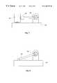
- FIG. 8is another side view of an alternative embodiment which shows a configuration of a base member, and a lever arm which moves the cutting blade in horizontal and vertical directions.
- FIG. 1Ais a front view of the preferred embodiment of the invention, and shows the system for forming precision cuts in a catheter, a guide wire, or other cylindrical objects.
- a catheterwill be referred to as the object being cut, although any cylindrical object can be substituted for the catheter.
- reference to the catheteris only for the convenience of writing in terms of a specific cylindrical object, and should not be considered a material limitation of the invention.
- referring to a catheterkeeps present in mind the objective of having a very precise cutting device, where precision is paramount in most medical applications.
- a catheteris only one embodiment of a medical application, but which easily represents the need for precision.
- the system 6 shown in FIGS. 1A and 1Bis comprised of several elements including a base member 10 for supporting the structure. Coupled in sliding engagement with a vertical base member 12 is a vertically movable member 14 which has a first vertical coupling face 16 and a first horizontal coupling face 18 . The vertical coupling face 16 is slidingly engaged with a base member vertical coupling face 20 .
- the mechanism 22 for enabling the sliding engagement between the vertical coupling face 16 and the base member vertical coupling face 20can be any appropriate apparatus.
- the important considerationis that the vertically movable member 14 not be permitted to move horizontally, or the precision of the system will be compromised. Therefore, the tolerances of the mechanism 22 must necessarily be small.
- a good example of an appropriate mechanism 22is well known to those skilled in the art as a crossed roller bearing slide.
- the shape of the vertically movable member 14is shown here as a small backwards “L”.
- An alternative shape for the vertically movable member 14is shown in FIG. 2 .
- the member 14is flipped over as compared to the embodiment of FIG. 1 A.
- the important feature of the member 14is that it provide two faces 16 , 18 which can be slidably engaged to move vertically and provide a second face on which another member can slidably engage to move horizontally.
- the system in FIGS. 1A and 1Bis also comprised of a horizontally movable member 24 which has a spindle end 26 and a second horizontal coupling face 28 .
- This horizontally movable member 24is slidably engaged at its second horizontal coupling face 28 to the vertically movable member 14 at its first horizontal coupling face 18 . It should be observed that the vertically movable member 14 and the horizontally movable member 24 are capable of moving independently of each other. In this way, the system achieves two independent degrees of freedom of movement.
- the spindle end 26 of the horizontally movable member 24provides a horizontal slot 30 in which a spindle 32 is disposed.
- the slot 30is generally circular to serve as a receptor for the round shaft 34 of the spindle 32 .
- the spindle shaft 34has disposed on a working end 36 thereof at least one circular saw blade 38 .
- the circular saw blade 38is disposed vertically on the spindle shaft 34 , but may also be angled in other embodiments.
- the spindle shaft 34is coupled to a drive motor by gears, belts, direct drive, or any other appropriate means (not shown) which will cause the spindle shaft 34 to rapidly rotate.
- the drive motor(not shown) can be disposed in any appropriate location relative to the spindle shaft.
- the spindle shaft 34is driven by a brushless DC motor through a toothed timing belt.
- the circular saw blade 38is typical of those found in the art.
- the cutting edge 40 of the saw blade 38is coated with industrial diamonds.
- the means for holding and otherwise manipulating a catheter 8 to be cutis the clamping member 50 .
- the clamping member 50is comprised of two major assemblies: the clamp 52 and the clamp feeding (supplying) means 54 , or the device which feeds the catheter 8 to and then through the clamp 52 .
- the clamping member 50is also coupled to the base member 10 and disposed to hold the clamp 52 in a position for easy feeding of the catheter 8 to the circular saw blade 38 .
- the clamp 52is of the type known to those skilled in the art as a collet clamp.
- a collet clampis a slotted cylindrical clamp inserted tightly into the tapered interior of a sleeve or chuck on a lathe to hold a cylindrical piece of work.
- FIG. 1Athe cylindrical shape of the clamp 52 is visible. It is slotted in that the clamping arms 58 are separate from each other so that they can pull away from the catheter 8 when disengaging, and then securely come together around the catheter 8 when engaging.
- a desirable feature of the clamp 52is that it is rotatably mounted within the clamping member 50 .
- the collet clamp 52can then rotate so as to dispose a different portion of the surface of the catheter 8 to the saw blades 38 .
- the mechanism for rotating the clamp 52is shown generally at 56 , and is comprised of the clamp 52 which is held in a frame which can rotate with respect to the saw blade 38 .
- the clamp feeding (supplying) means 54 seen in FIG. 1Bis shown in this preferred embodiment to be comprised of a pinch roller assembly 60 , 62 working in conjunction with a feed roller 66 .
- the pinch roller assembly 60 , 62feeds the catheter 8 to the clamp 52 by using friction created between two opposing members 60 , 66 .
- the upper memberis the pinch roller 60 .
- the lower memberis the feed roller 66 .
- the feed roller 66has an axle 68 mounted in the clamp feeding means 54 so that the feed roller 66 can roll.
- the pinch roller 60is disposed at the end of a lever arm 62 which pivots at a pivoting end 70 .
- Located distally from the pinch roller assembly along the length of the lever armis a hole 72 .
- One end of a spring 64is inserted therethrough, and the other end of the spring 64 is coupled at another hole 74 to the clamp feeding means 54 .
- the spring 64provides the tension necessary for the feed roller 64 to push the catheter 8 to the clamp
- the operation of the assembly 6is as follows. First, the uncut catheter 8 is placed between the pinch roller 60 and the feed roller 66 . This can be done by raising the lever arm 62 by stretching the spring 64 . Releasing the lever arm 62 causes the pinch roller 60 to push down against the feed roller 66 , with the catheter 8 disposed therebetween. A drive mechanism (not shown) is coupled to the feed roller 66 to cause it to roll and thereby push the catheter 8 toward the clamp 52 .
- the clamp 52should be in a disengaged position (hole through clamp is larger than diameter of the catheter 8 ) so that the catheter 8 can be fed easily therethrough. After passing through the clamp 52 , the catheter 8 is fed sufficiently far past the circular saw blade 38 so that it is in a proper position to have an incision made in or through its surface.
- the first movement of the saw blade 38is 1 ) horizontal advancement toward the catheter 8 . This is accomplished by moving the horizontally movable member 24 relative to the vertically movable member 14 to which it is attached. The horizontally movable member 24 is moved until it has reached the depth of the incision to be made in the catheter 8 .
- the next step 2 )comprises the vertically movable member 14 moving upwards relative to the base 10 to which is coupled to thereby make the cut.
- the saw blade 38is then immediately retracted by moving the vertically movable member 14 away from the catheter 8 .
- the horizontal memberis moved only when the next cut is at a different depth or when all cutting is complete.
- the collet clamp 52is released as step 4 ).
- the catheter 8is then fed through the clamp 52 by the feed roller 66 as step 5 ).
- the collet clamp 52is then re-engaged in step 6 ) and, if necessary, the collet clamp 52 is rotated to expose a different position of the catheter 8 to the saw blade 38 .
- the saw blade 38is then moved horizontally if the depth of cut is to change, and then vertically to make the cut and steps 1 ) through 7 ) repeat as often as necessary until all the incisions have been made or the catheter 8 is no longer capable of being grasped by the feed roller 66 and opposing pinch roller 60 .
- the clamp 52holds the catheter 8 steady.
- the catheter 8is fed through the clamp 52 by causing the clamp to disengage from around the catheter 8 .
- the catheter 8is fed through the clamp 52 until the next incision point on the catheter 8 is in position relative to the saw blade 38 .
- the clamp 52re-engages so as to be disposed snugly around the catheter 8 to again prevent movement of the catheter 8 during cutting.
- the width of a cut into the catheter 8is limited to the width of the circular saw blade 38 .
- a wider cuttherefore requires that the catheter 8 be advanced slightly past the saw blade 38 .
- advancementdoes not take place while making a cut.
- the saw blade 38must be withdrawn so that the clamp 52 can disengage from around the catheter 8 while it is advanced. This is necessary because allowing cutting of the catheter 8 when the clamp is disengaged would create an imprecise or useless cut.
- FIGS. 4A and 4Bshow that the clamping means 52 has been modified.
- a stationary support surface 110is provided with a slot 112 therein for supporting the catheter 8 from below.
- the slot 112guides and holds the catheter 8 before, during and after cutting. Holding the catheter 8 not only allows more precise cutting, but prevents damage to the catheter 8 which might otherwise occur.
- a movable clamping member 114 or anvilis also provided to thereby apply force to the catheter 8 which is clamped between the anvil 114 and the slotted support surface 110 .
- FIG. 4Balso shows that the anvil 114 has a mechanism 116 which allows the anvil 114 to move vertically with respect to the support surface 110 . In FIG. 4B the vertical movement mechanism 116 is shown as bearings.
- FIG. 4Cis provided to illustrate an alternative embodiment of the anvil 114 .
- the anvil 114has a slot 158 which will hold the catheter 8 more securely for cutting.
- FIG. 5illustrates a modification to the spindle 32 and saw blade 38 arrangement shown in FIGS. 1A and 1B.
- a plurality of saw blades 38are shown as being mounted in parallel on the same spindle 32 .
- the saw blades 38are necessarily coaxial.
- the saw blades 38have the same diameter so that no individual saw blade 38 makes a deeper incision in the catheter 8 than any of the others.
- saw blades of varying diametersmight be mounted on the same spindle 32 to achieve a consistent pattern of cuts having different depths.
- FIG. 6is an illustration of another alternative embodiment of the present invention.
- the vertically movable member 14is shown having another shape which enables it to have disposed thereon two horizontally movable members 24 , each having its own associated saw blade or blades 38 .
- This embodimentenables the catheter 8 to be simultaneously cut at different circumferentially defined points on the catheter surface. This is especially useful in making multiple cuts in catheters, for example, on diametrically opposed positions on the catheter 8 .
- the preferred embodimenthas been defined as having a horizontally movable member with the spindle for the saw blade coupled thereto, the placement of the vertically and horizontally movable members can be switched as shown in FIG. 7 .
- the horizontally movable member 144is coupled to the base member 142 and the vertically movable member 146 , and the vertically movable member 146 has a spindle 148 rotatably coupled thereto.
- a lever arm 150is pivotally connected to the base member 154 , and is capable of movement in at least two degrees of freedom so that it can move vertically and horizontally to position a spindle end 152 .
- rotating the catheteris not limited to using a rotatable clamping mechanism.
- the clampcan be non-rotatable and disengaged to enable the catheter feeding mechanism to rotate the catheter, and then re-engage the clamp to make additional incisions.
- the clamp and the catheter feeding mechanismcan be rotated together before additional incisions are made.
- Alternative aspects of the inventioninclude the substitution of a non-mechanical cutting instrument for the rotating blade of the presently preferred embodiment.
- a lasercan be provided for cutting through materials which are mounted on the system.
- rotating bladesare not the only type of mechanical blade which can be utilized.
- Conventional “sawing” bladescan also be provided.
Landscapes
- Health & Medical Sciences (AREA)
- Life Sciences & Earth Sciences (AREA)
- Engineering & Computer Science (AREA)
- Animal Behavior & Ethology (AREA)
- Veterinary Medicine (AREA)
- Public Health (AREA)
- General Health & Medical Sciences (AREA)
- Biomedical Technology (AREA)
- Heart & Thoracic Surgery (AREA)
- Anesthesiology (AREA)
- Surgery (AREA)
- Pulmonology (AREA)
- Biophysics (AREA)
- Mechanical Engineering (AREA)
- Hematology (AREA)
- Medical Informatics (AREA)
- Nuclear Medicine, Radiotherapy & Molecular Imaging (AREA)
- Vascular Medicine (AREA)
- Reproductive Health (AREA)
- Molecular Biology (AREA)
- Media Introduction/Drainage Providing Device (AREA)
- Sawing (AREA)
- Details Of Cutting Devices (AREA)
- Surgical Instruments (AREA)
- Feeding Of Workpieces (AREA)
- Nonmetal Cutting Devices (AREA)
Abstract
Description
This application is a division of U.S. patent application Ser. No. 08/714,555, filed on Sep. 16, 1996 now U.S. Pat. No. 6,014,919.
1. Field of the Invention
The present invention pertains to making precision cuts in catheters and guide wires. Specifically, a device for holding, advancing, rotating and then cutting a catheter or guide wire is provided which is able to manipulate the catheter or guide wire in two degrees of freedom to enable precision control of the location of the cuts. Various clamping mechanisms are provided for manipulating the catheter or guide wire, resulting in controlled variation in mechanical properties.
2. State of the Art
Making cuts in catheters and guide wires requires precision in order to ensure reliability because of the medical applications in which they are used. However, it is also important to control costs of production so that costs to the health care industry can be minimized.
The state of the art is typified by such devices as grinding wires, wound coils, and lasers for making the cuts. But these devices often suffer from high cost or imprecise or difficult control mechanisms for properly positioning both the device to make the cut and the cylindrical object to be cut.
What is needed is a method and apparatus for making cuts in catheters and guide wires which allows precise control of characteristics of the cuts. This entails precision holding, advancement and rotation of the generally cylindrical object while at least one saw blade is itself advanced to make the cut and retracted afterward.
It is therefore an object of the present invention to provide a method and apparatus for forming precision cuts in elongate cylindrical objects including catheters and catheter guide wires.
It is another object to provide a method and apparatus for forming precision cuts by manipulating a cylindrical object in two degrees of freedom to control the parameters of the cuts.
It is yet another object to provide a method and apparatus for holding, advancing and rotating a cylindrical object to be cut.
These and other objects are realized in a preferred embodiment of a system for making cuts in a catheter, guide wire or other elongate cylindrical object having a lengthwise axis. The system generally comprises a securing means for repeatedly releasing and then holding the elongate object in a position suitable for cutting it at an angle or transversely relative to its lengthwise axis, a manipulating means for moving the elongate object so that it can be disposed in the position suitable for cutting when it is released by the securing means, and a cutting means for forming the at least one precision cut in the elongate object to any desired depth. The securing means preferably comprises a rotatable collet clamp. The manipulating means preferably comprises a pinch roller assembly for advancing and holding the elongate object. The cutting means is preferably a mechanical blade mounted on a rotatable spindle. The clamp is able to hold the object to be cut, as well as position it by, for example, rotation to thereby expose the entire circumference of the cylindrical object to the saw blade. By releasing the clamp, the pinch roller advances the cylindrical object before the clamp is re-engaged to securely hold the cylindrical object for cutting.
The securing means, manipulating means, and cutting means are preferably mounted on a base. The rotating spindle is free to move vertically and horizontally with respect to the base to thereby control the location, length, depth and angle of the cuts in the cylindrical object disposed adjacent thereto.
Another aspect of the invention is the ability to make precision cuts by providing means for controlling the rotation and advancement of the object to be cut and movement of the saw blade spindle member.
Another aspect is the ability to simultaneously make a plurality of cuts in the object. This is accomplished with a saw blade having a plurality of blades in parallel. Even more cuts can be made by providing more than one saw blade spindle member, where each is independently movable in two degrees of freedom.
Another aspect of the invention is to provide more than one spindle member so that blades can simultaneously make precision cuts at different locations along the length of the cylindrical object.
These and other objects, features, advantages and alternative aspects of the present invention will become apparent to those skilled in the art from a consideration of the following detailed description taken in combination with the accompanying drawings.
FIG. 1A is a front elevational view of a preferred embodiment made in accordance with the principles of the present invention.
FIG. 1B is a side elevational view of the invention shown in FIG.1A.
FIG. 2 is an alternative embodiment of a vertically moving member shown reversed in orientation with respect to FIGS. 1A and 1B.
FIG. 3 is an alternative embodiment of a horizontally moving member shown reversed in orientation with respect to FIGS. 1A and 1B.
FIG. 4A is a front elevational view of an alternative embodiment for the clamping means.
FIG. 4B is a side elevational view of the alternative embodiment for the clamping means of FIG.4A.
FIG. 4C is a front view which shows that the anvil has a slot.
FIG. 5 is an alternative saw blade assembly which can be used in all embodiments of the present invention.
FIG. 6 is an alternative embodiment which uses two saw blade assemblies to simultaneously make incisions in the catheter.
FIG. 7 is a side view of an alternative embodiment which shows a configuration with a base member, a horizontally movable member, and a vertically moveable member.
FIG. 8 is another side view of an alternative embodiment which shows a configuration of a base member, and a lever arm which moves the cutting blade in horizontal and vertical directions.
Reference will now be made to the drawings in which the various elements of the present invention will be given numerical designations and in which the invention will be discussed so as to enable one skilled in the art to make and use the invention.
The present invention is illustrated in FIGS. 1A and 1B. FIG. 1A is a front view of the preferred embodiment of the invention, and shows the system for forming precision cuts in a catheter, a guide wire, or other cylindrical objects. For purposes of keeping in mind the intended use of the present invention, a catheter will be referred to as the object being cut, although any cylindrical object can be substituted for the catheter. However, reference to the catheter is only for the convenience of writing in terms of a specific cylindrical object, and should not be considered a material limitation of the invention. However, referring to a catheter keeps present in mind the objective of having a very precise cutting device, where precision is paramount in most medical applications. Furthermore, a catheter is only one embodiment of a medical application, but which easily represents the need for precision.
Thesystem 6 shown in FIGS. 1A and 1B is comprised of several elements including abase member 10 for supporting the structure. Coupled in sliding engagement with avertical base member 12 is a verticallymovable member 14 which has a firstvertical coupling face 16 and a firsthorizontal coupling face 18. Thevertical coupling face 16 is slidingly engaged with a base membervertical coupling face 20.
Themechanism 22 for enabling the sliding engagement between thevertical coupling face 16 and the base membervertical coupling face 20 can be any appropriate apparatus. The important consideration is that the verticallymovable member 14 not be permitted to move horizontally, or the precision of the system will be compromised. Therefore, the tolerances of themechanism 22 must necessarily be small. A good example of anappropriate mechanism 22 is well known to those skilled in the art as a crossed roller bearing slide.
The shape of the verticallymovable member 14 is shown here as a small backwards “L”. An alternative shape for the verticallymovable member 14 is shown in FIG.2. Themember 14 is flipped over as compared to the embodiment of FIG.1A. The important feature of themember 14 is that it provide twofaces
The system in FIGS. 1A and 1B is also comprised of a horizontallymovable member 24 which has aspindle end 26 and a secondhorizontal coupling face 28. This horizontallymovable member 24 is slidably engaged at its secondhorizontal coupling face 28 to the verticallymovable member 14 at its firsthorizontal coupling face 18. It should be observed that the verticallymovable member 14 and the horizontallymovable member 24 are capable of moving independently of each other. In this way, the system achieves two independent degrees of freedom of movement.
Thespindle end 26 of the horizontallymovable member 24 provides a horizontal slot30 in which aspindle 32 is disposed.
The slot30 is generally circular to serve as a receptor for theround shaft 34 of thespindle 32. Thespindle shaft 34 has disposed on a workingend 36 thereof at least onecircular saw blade 38. Thecircular saw blade 38 is disposed vertically on thespindle shaft 34, but may also be angled in other embodiments.
Thespindle shaft 34 is coupled to a drive motor by gears, belts, direct drive, or any other appropriate means (not shown) which will cause thespindle shaft 34 to rapidly rotate. The drive motor (not shown) can be disposed in any appropriate location relative to the spindle shaft. In a preferred embodiment, thespindle shaft 34 is driven by a brushless DC motor through a toothed timing belt.
Thecircular saw blade 38 is typical of those found in the art. In a preferred embodiment, thecutting edge 40 of thesaw blade 38 is coated with industrial diamonds.
The means for holding and otherwise manipulating acatheter 8 to be cut is the clampingmember 50. The clampingmember 50 is comprised of two major assemblies: theclamp 52 and the clamp feeding (supplying) means54, or the device which feeds thecatheter 8 to and then through theclamp 52. The clampingmember 50 is also coupled to thebase member 10 and disposed to hold theclamp 52 in a position for easy feeding of thecatheter 8 to thecircular saw blade 38.
In the preferred embodiment, theclamp 52 is of the type known to those skilled in the art as a collet clamp. A collet clamp is a slotted cylindrical clamp inserted tightly into the tapered interior of a sleeve or chuck on a lathe to hold a cylindrical piece of work. In FIG. 1A, the cylindrical shape of theclamp 52 is visible. It is slotted in that the clampingarms 58 are separate from each other so that they can pull away from thecatheter 8 when disengaging, and then securely come together around thecatheter 8 when engaging.
In a preferred embodiment, a desirable feature of theclamp 52 is that it is rotatably mounted within the clampingmember 50. Thecollet clamp 52 can then rotate so as to dispose a different portion of the surface of thecatheter 8 to thesaw blades 38. The mechanism for rotating theclamp 52 is shown generally at56, and is comprised of theclamp 52 which is held in a frame which can rotate with respect to thesaw blade 38.
The clamp feeding (supplying) means54 seen in FIG. 1B is shown in this preferred embodiment to be comprised of apinch roller assembly feed roller 66. As FIG. 1B should make clear, thepinch roller assembly catheter 8 to theclamp 52 by using friction created between two opposingmembers pinch roller 60. The lower member is thefeed roller 66. Thefeed roller 66 has anaxle 68 mounted in the clamp feeding means54 so that thefeed roller 66 can roll. Thepinch roller 60 is disposed at the end of alever arm 62 which pivots at a pivotingend 70. Located distally from the pinch roller assembly along the length of the lever arm is ahole 72. One end of aspring 64 is inserted therethrough, and the other end of thespring 64 is coupled at anotherhole 74 to the clamp feeding means54. Thespring 64 provides the tension necessary for thefeed roller 64 to push thecatheter 8 to theclamp 52.
Having described most of the components in a preferred embodiment of thecatheter cutting assembly 6, the operation of theassembly 6 is as follows. First, theuncut catheter 8 is placed between thepinch roller 60 and thefeed roller 66. This can be done by raising thelever arm 62 by stretching thespring 64. Releasing thelever arm 62 causes thepinch roller 60 to push down against thefeed roller 66, with thecatheter 8 disposed therebetween. A drive mechanism (not shown) is coupled to thefeed roller 66 to cause it to roll and thereby push thecatheter 8 toward theclamp 52. Theclamp 52 should be in a disengaged position (hole through clamp is larger than diameter of the catheter8) so that thecatheter 8 can be fed easily therethrough. After passing through theclamp 52, thecatheter 8 is fed sufficiently far past thecircular saw blade 38 so that it is in a proper position to have an incision made in or through its surface.
When thecatheter 8 is positioned correctly, theclamp 52 is engaged and thesaw blade 38 is advanced to make cutting contact. Before cutting, thesaw blade 38 will always be positioned in a retracted position. The retracted position is both vertically below and horizontally pulled away from thecatheter 8. The first movement of thesaw blade 38 is1) horizontal advancement toward thecatheter 8. This is accomplished by moving the horizontallymovable member 24 relative to the verticallymovable member 14 to which it is attached. The horizontallymovable member 24 is moved until it has reached the depth of the incision to be made in thecatheter 8. The next step2) comprises the verticallymovable member 14 moving upwards relative to the base10 to which is coupled to thereby make the cut. Thesaw blade 38 is then immediately retracted by moving the verticallymovable member 14 away from thecatheter 8. The horizontal member is moved only when the next cut is at a different depth or when all cutting is complete.
If another cut is to be made, thecollet clamp 52 is released as step4). Thecatheter 8 is then fed through theclamp 52 by thefeed roller 66 as step5). Thecollet clamp 52 is then re-engaged in step6) and, if necessary, thecollet clamp 52 is rotated to expose a different position of thecatheter 8 to thesaw blade 38. Thesaw blade 38 is then moved horizontally if the depth of cut is to change, and then vertically to make the cut and steps1) through7) repeat as often as necessary until all the incisions have been made or thecatheter 8 is no longer capable of being grasped by thefeed roller 66 and opposingpinch roller 60.
The above description of the operation of thecatheter cutting system 6 describes the different roles served by theclamp 52. When thecircular saw blade 38 is making a cut in thecatheter 8, theclamp 52 holds thecatheter 8 steady. When the cut has been made in thecatheter 8, thecatheter 8 is fed through theclamp 52 by causing the clamp to disengage from around thecatheter 8. After being disengaged, thecatheter 8 is fed through theclamp 52 until the next incision point on thecatheter 8 is in position relative to thesaw blade 38. Theclamp 52 re-engages so as to be disposed snugly around thecatheter 8 to again prevent movement of thecatheter 8 during cutting.
It should be recognized from the description above that the width of a cut into thecatheter 8 is limited to the width of thecircular saw blade 38. A wider cut therefore requires that thecatheter 8 be advanced slightly past thesaw blade 38. However, advancement does not take place while making a cut. Thesaw blade 38 must be withdrawn so that theclamp 52 can disengage from around thecatheter 8 while it is advanced. This is necessary because allowing cutting of thecatheter 8 when the clamp is disengaged would create an imprecise or useless cut.
Variations of the preferred embodiment are illustrated in FIGS. 4A and 4B which show that the clamping means52 has been modified. As can be seen in FIG. 4A, astationary support surface 110 is provided with aslot 112 therein for supporting thecatheter 8 from below. Theslot 112 guides and holds thecatheter 8 before, during and after cutting. Holding thecatheter 8 not only allows more precise cutting, but prevents damage to thecatheter 8 which might otherwise occur. Amovable clamping member 114 or anvil is also provided to thereby apply force to thecatheter 8 which is clamped between theanvil 114 and the slottedsupport surface 110. FIG. 4B also shows that theanvil 114 has amechanism 116 which allows theanvil 114 to move vertically with respect to thesupport surface 110. In FIG. 4B thevertical movement mechanism 116 is shown as bearings.
FIG. 4C is provided to illustrate an alternative embodiment of theanvil 114. As shown, theanvil 114 has aslot 158 which will hold thecatheter 8 more securely for cutting.
FIG. 5 illustrates a modification to thespindle 32 and sawblade 38 arrangement shown in FIGS. 1A and 1B. Specifically, a plurality ofsaw blades 38 are shown as being mounted in parallel on thesame spindle 32. This also means that thesaw blades 38 are necessarily coaxial. It is also preferred that thesaw blades 38 have the same diameter so that no individual sawblade 38 makes a deeper incision in thecatheter 8 than any of the others. However, it should be apparent that if thespindle 32 or thesaw blades 38 are easily detachable from thesystem 6, then saw blades of varying diameters might be mounted on thesame spindle 32 to achieve a consistent pattern of cuts having different depths.
FIG. 6 is an illustration of another alternative embodiment of the present invention. The verticallymovable member 14 is shown having another shape which enables it to have disposed thereon two horizontallymovable members 24, each having its own associated saw blade orblades 38. This embodiment enables thecatheter 8 to be simultaneously cut at different circumferentially defined points on the catheter surface. This is especially useful in making multiple cuts in catheters, for example, on diametrically opposed positions on thecatheter 8.
It should be noted that while the preferred embodiment has been defined as having a horizontally movable member with the spindle for the saw blade coupled thereto, the placement of the vertically and horizontally movable members can be switched as shown in FIG.7. In this arrangement, the horizontallymovable member 144 is coupled to thebase member 142 and the verticallymovable member 146, and the verticallymovable member 146 has aspindle 148 rotatably coupled thereto.
In another alternative embodiment of the present invention, shown in FIG. 8, alever arm 150 is pivotally connected to thebase member 154, and is capable of movement in at least two degrees of freedom so that it can move vertically and horizontally to position aspindle end 152.
Another aspect of the invention which should be clarified is that rotating the catheter is not limited to using a rotatable clamping mechanism. For example, the clamp can be non-rotatable and disengaged to enable the catheter feeding mechanism to rotate the catheter, and then re-engage the clamp to make additional incisions. Furthermore, the clamp and the catheter feeding mechanism can be rotated together before additional incisions are made.
Alternative aspects of the invention include the substitution of a non-mechanical cutting instrument for the rotating blade of the presently preferred embodiment. For example, a laser can be provided for cutting through materials which are mounted on the system.
It should also be realized that rotating blades are not the only type of mechanical blade which can be utilized. Conventional “sawing” blades can also be provided.
It is to be understood that the above-described embodiments are only illustrative of the application of the principles of the present invention. Numerous modifications and alternative arrangements may be devised by those skilled in the art without departing from the spirit and scope of the present invention. The appended claims are intended to cover such modifications and arrangements.
Claims (15)
1. A system configured for forming at least one precision cut in an elongate object, wherein the precision cut is generally at an angle or transverse relative to a lengthwise axis of the elongate object, said system comprising:
a base; clamp supported by the base and configured for selectively grasping and stabilizing the elongate member by repeatedly releasing and then holding the elongate object in a position suitable for cutting;
a first roller and a second roller comprising a pinch roller and feed roller, the first and second rollers being rotatable supported by the base, and configured to move the elongate object in a direction parallel to the lengthwise axis, said rollers being rotatable with the elongate object around the lengthwise axis of the elongate member;
a mechanism configured for rotating the elongate object, said mechanism being supported by the base and configured to rotate the first and second roller; and,
a horizontally moveable member supported by the base and configured for moving horizontally with respect to the base,
a cutting means carried by the horizontally moveable member and moveable therewith toward and away from the elongate object, the cutting means being configured for forming the at least one precision cut in the elongate object to a desired depth.
2. A cutting system as defined in claim1, further comprising a vertically moveable member disposed between the horizontally moveable member and the base, the horizontally moveable member being carried by the vertically moveable member, whereby the cutting means is moveable vertically and horizontally.
3. A cutting system as defined in claim1, wherein the clamp further comprises a plurality of opposing surfaces which are movable to press against the elongate object and hold the elongate object immobile.
4. A cutting system as defined in claim3 wherein the clamping device is further comprised of means for rotating the clamp is rotatable about the lengthwise axis of the elongate object.
5. A cutting system as defined in claim3 wherein the comprises of a collet clamp.
6. A cutting system as defined in claim1, wherein the cutting means is selected from the group of cutting means consisting of a mechanical blade and a laser.
7. The cutting system as defined in claim6 wherein the mechanical blade is selected from the group of mechanical blades consisting of rotating saw blades and non-rotating saw blades.
8. A cutting system as defined in claim1, wherein the clamp comprises a collet clamp.
9. A cutting system as defined in claim1, wherein the clamp is rotatable with the mechanism configured for rotating the elongate, and wherein the clamp is rotatably carried by the base.
10. A cutting system as defined in claim1, wherein the clamp and the pinch roller and feed roller are rotatably supported by the base and are configured to rotate together.
11. A cutting system as defined in claim1, further comprising a crossed roller bearing slide, and wherein the horizontally movable member is carried by said slide.
12. A system configured for forming at least one precision cut in an elongate object, wherein the precision cut is generally at an angle or transverse relative to a lengthwise axis of the elongate object, said system comprising: a base;
a collet clamp configured for repeatedly releasing and then holding the elongate object in a position suitable for cutting the elongate object at an angle or transversely relative to the lengthwise axis;
a pinch roller assembly configured for manipulating the elongate object so that the elongate object can be moved to a position suitable for cutting when the object is released by the collet clamp, said pinch roller assembly comprising:
a first wheel configured for supporting and forcing the elongate object to move toward the clamping means when the collet clamp is disengaged;
a second wheel configured for applying a force to the elongate object to thereby hold the elongate object against the first wheel, thereby cooperating with the first wheel in providing friction to push the cylindrical object to the collet clamp; and
a lever arm coupled to the base at a pivoting end, and coupled to the second wheel at a movable end;
a spring means coupled between the lever arm and the base and cooperating therewith to provide force to the second wheel for application to the elongate object; a mechanism configured for rotating the elongate object, said mechanism being supported by the base and configured to rotate said pinch roller assembly; and
a movable member carrying a spindle configured to rotatable carry a rotatable blade configured for forming the at least one precision cut in the elongate object to any desired depth, said blade being moveable relative to the elongate object being held by the collet clamp such that the precision cut can be made at an angle or transversely relative to the lengthwise axis of the elongate object.
13. The system as defined in claim12, wherein the clamp is rotatable about the lengthwise axis of the elongate object.
14. The system as defined in claim12, wherein the blade is moveable toward and away from the elongate member in substantially horizontal directions.
15. The system as defined in claim14, further comprising a vertically movable member configured to carry the movable member, wherein the blade is moveable toward and away from the elongate member in substantially vertical directions.
Priority Applications (3)
| Application Number | Priority Date | Filing Date | Title |
|---|---|---|---|
| US09/366,360US6260458B1 (en) | 1996-09-16 | 1999-08-03 | Method and apparatus for forming cuts in catheters, guide wires, and the like |
| US09/908,445US6553880B2 (en) | 1996-09-16 | 2001-07-17 | Micromachining system |
| US09/996,878US20020058882A1 (en) | 1998-06-22 | 2001-11-30 | Biopsy localization method and device |
Applications Claiming Priority (2)
| Application Number | Priority Date | Filing Date | Title |
|---|---|---|---|
| US08/714,555US6014919A (en) | 1996-09-16 | 1996-09-16 | Method and apparatus for forming cuts in catheters, guidewires, and the like |
| US09/366,360US6260458B1 (en) | 1996-09-16 | 1999-08-03 | Method and apparatus for forming cuts in catheters, guide wires, and the like |
Related Parent Applications (2)
| Application Number | Title | Priority Date | Filing Date |
|---|---|---|---|
| US08/714,555DivisionUS6014919A (en) | 1996-09-16 | 1996-09-16 | Method and apparatus for forming cuts in catheters, guidewires, and the like |
| US09/470,606DivisionUS6766720B1 (en) | 1996-09-16 | 1999-12-22 | Method and apparatus for forming cuts in catheters, guidewires and the like |
Related Child Applications (3)
| Application Number | Title | Priority Date | Filing Date |
|---|---|---|---|
| US09/470,606Continuation-In-PartUS6766720B1 (en) | 1996-09-16 | 1999-12-22 | Method and apparatus for forming cuts in catheters, guidewires and the like |
| US09/900,801ContinuationUS6699205B2 (en) | 1998-06-22 | 2001-07-06 | Biopsy localization method and device |
| US09/908,445Continuation-In-PartUS6553880B2 (en) | 1996-09-16 | 2001-07-17 | Micromachining system |
Publications (1)
| Publication Number | Publication Date |
|---|---|
| US6260458B1true US6260458B1 (en) | 2001-07-17 |
Family
ID=24870501
Family Applications (4)
| Application Number | Title | Priority Date | Filing Date |
|---|---|---|---|
| US08/714,555Expired - LifetimeUS6014919A (en) | 1996-09-16 | 1996-09-16 | Method and apparatus for forming cuts in catheters, guidewires, and the like |
| US09/366,360Expired - LifetimeUS6260458B1 (en) | 1996-09-16 | 1999-08-03 | Method and apparatus for forming cuts in catheters, guide wires, and the like |
| US09/452,233Expired - LifetimeUS6431039B1 (en) | 1996-09-16 | 1999-12-01 | Method and apparatus for forming cuts in catheters, guide wires, and the like |
| US09/470,606Expired - LifetimeUS6766720B1 (en) | 1996-09-16 | 1999-12-22 | Method and apparatus for forming cuts in catheters, guidewires and the like |
Family Applications Before (1)
| Application Number | Title | Priority Date | Filing Date |
|---|---|---|---|
| US08/714,555Expired - LifetimeUS6014919A (en) | 1996-09-16 | 1996-09-16 | Method and apparatus for forming cuts in catheters, guidewires, and the like |
Family Applications After (2)
| Application Number | Title | Priority Date | Filing Date |
|---|---|---|---|
| US09/452,233Expired - LifetimeUS6431039B1 (en) | 1996-09-16 | 1999-12-01 | Method and apparatus for forming cuts in catheters, guide wires, and the like |
| US09/470,606Expired - LifetimeUS6766720B1 (en) | 1996-09-16 | 1999-12-22 | Method and apparatus for forming cuts in catheters, guidewires and the like |
Country Status (12)
| Country | Link |
|---|---|
| US (4) | US6014919A (en) |
| EP (1) | EP0934141B1 (en) |
| JP (2) | JP2001500808A (en) |
| KR (1) | KR20000036139A (en) |
| CN (1) | CN1230914A (en) |
| AT (1) | ATE310615T1 (en) |
| AU (1) | AU733966B2 (en) |
| BR (1) | BR9712829A (en) |
| CA (1) | CA2266685C (en) |
| DE (1) | DE69734719T2 (en) |
| TW (1) | TW412468B (en) |
| WO (1) | WO1998010694A2 (en) |
Cited By (75)
| Publication number | Priority date | Publication date | Assignee | Title |
|---|---|---|---|---|
| US20050210643A1 (en)* | 2002-10-04 | 2005-09-29 | Lumitex, Inc. | Transparent light emitting members and method of manufacture |
| US20060271149A1 (en)* | 2005-05-25 | 2006-11-30 | Chestnut Medical Technologies, Inc. | System and method for delivering and deploying an occluding device within a vessel |
| US20060271153A1 (en)* | 2005-05-25 | 2006-11-30 | Chestnut Medical Technologies, Inc. | System and method for delivering and deploying an occluding device within a vessel |
| US7169118B2 (en) | 2003-02-26 | 2007-01-30 | Scimed Life Systems, Inc. | Elongate medical device with distal cap |
| US20070135763A1 (en)* | 2005-12-12 | 2007-06-14 | Musbach Frank A | Micromachined medical devices |
| US20070208405A1 (en)* | 2006-03-06 | 2007-09-06 | Boston Scientific Scimed, Inc. | Stent delivery catheter |
| US20070248307A1 (en)* | 2002-10-04 | 2007-10-25 | Page David J | Transparent light emitting members and method of manufacture |
| US20080077085A1 (en)* | 2006-09-27 | 2008-03-27 | Boston Scientific Scimed, Inc. | Catheter shaft designs |
| US20080294231A1 (en)* | 2007-05-16 | 2008-11-27 | Boston Scientific Scimed, Inc. | Stent Delivery Catheter |
| US20090048653A1 (en)* | 2007-08-09 | 2009-02-19 | Boston Scientific Scimed, Inc. | Endoprosthesis holder |
| US7540865B2 (en) | 2003-03-27 | 2009-06-02 | Boston Scientific Scimed, Inc. | Medical device |
| US20090157048A1 (en)* | 2007-12-18 | 2009-06-18 | Boston Scientific Scimed, Inc. | Spiral cut hypotube |
| US20090177185A1 (en)* | 2008-01-03 | 2009-07-09 | Boston Scientific Scimed, Inc. | Cut tubular members for a medical device and methods for making and using the same |
| US20090224490A1 (en)* | 2008-03-10 | 2009-09-10 | Paul Robert Homrich | Material cutter clamping collet |
| US7632242B2 (en) | 2004-12-09 | 2009-12-15 | Boston Scientific Scimed, Inc. | Catheter including a compliant balloon |
| US20090318947A1 (en)* | 2005-05-25 | 2009-12-24 | Chestnut Medical Technologies, Inc. | System and method for delivering and deploying an occluding device within a vessel |
| US20100139465A1 (en)* | 2008-12-08 | 2010-06-10 | Next Vascular, Llc | Micro-Cutting Machine for Forming Cuts in Products |
| US20100256606A1 (en)* | 2009-04-03 | 2010-10-07 | Scientia Vascular, Llc | Micro-fabricated Guidewire Devices Formed Having Elastomeric Fill Compositions |
| US20100256603A1 (en)* | 2009-04-03 | 2010-10-07 | Scientia Vascular, Llc | Micro-fabricated Catheter Devices Formed Having Elastomeric Fill Compositions |
| US20100256604A1 (en)* | 2009-04-03 | 2010-10-07 | Scientia Vascular, Llc | Micro-fabricated Catheter Devices Formed Having Elastomeric Compositions |
| US7824345B2 (en) | 2003-12-22 | 2010-11-02 | Boston Scientific Scimed, Inc. | Medical device with push force limiter |
| US7841994B2 (en) | 2007-11-02 | 2010-11-30 | Boston Scientific Scimed, Inc. | Medical device for crossing an occlusion in a vessel |
| US7850623B2 (en) | 2005-10-27 | 2010-12-14 | Boston Scientific Scimed, Inc. | Elongate medical device with continuous reinforcement member |
| US7878984B2 (en) | 2002-07-25 | 2011-02-01 | Boston Scientific Scimed, Inc. | Medical device for navigation through anatomy and method of making same |
| WO2011014550A1 (en) | 2009-07-30 | 2011-02-03 | Boston Scientific Scimed, Inc. | Reconstrainment band with reduced removal interference |
| US7914467B2 (en) | 2002-07-25 | 2011-03-29 | Boston Scientific Scimed, Inc. | Tubular member having tapered transition for use in a medical device |
| US7914466B2 (en) | 1995-12-07 | 2011-03-29 | Precision Vascular Systems, Inc. | Medical device with collapse-resistant liner and method of making same |
| US8105246B2 (en) | 2007-08-03 | 2012-01-31 | Boston Scientific Scimed, Inc. | Elongate medical device having enhanced torque and methods thereof |
| US8137293B2 (en) | 2009-11-17 | 2012-03-20 | Boston Scientific Scimed, Inc. | Guidewires including a porous nickel-titanium alloy |
| US8377035B2 (en) | 2003-01-17 | 2013-02-19 | Boston Scientific Scimed, Inc. | Unbalanced reinforcement members for medical device |
| US8376961B2 (en) | 2008-04-07 | 2013-02-19 | Boston Scientific Scimed, Inc. | Micromachined composite guidewire structure with anisotropic bending properties |
| US8382825B2 (en) | 2004-05-25 | 2013-02-26 | Covidien Lp | Flexible vascular occluding device |
| US8394119B2 (en) | 2006-02-22 | 2013-03-12 | Covidien Lp | Stents having radiopaque mesh |
| US8398701B2 (en) | 2004-05-25 | 2013-03-19 | Covidien Lp | Flexible vascular occluding device |
| US8409114B2 (en) | 2007-08-02 | 2013-04-02 | Boston Scientific Scimed, Inc. | Composite elongate medical device including distal tubular member |
| US8449526B2 (en) | 2001-07-05 | 2013-05-28 | Boston Scientific Scimed, Inc. | Torqueable soft tip medical device and method of usage |
| US8535243B2 (en) | 2008-09-10 | 2013-09-17 | Boston Scientific Scimed, Inc. | Medical devices and tapered tubular members for use in medical devices |
| US8551020B2 (en) | 2006-09-13 | 2013-10-08 | Boston Scientific Scimed, Inc. | Crossing guidewire |
| US8551021B2 (en) | 2010-03-31 | 2013-10-08 | Boston Scientific Scimed, Inc. | Guidewire with an improved flexural rigidity profile |
| US8556914B2 (en) | 2006-12-15 | 2013-10-15 | Boston Scientific Scimed, Inc. | Medical device including structure for crossing an occlusion in a vessel |
| US8617234B2 (en) | 2004-05-25 | 2013-12-31 | Covidien Lp | Flexible vascular occluding device |
| US8623067B2 (en) | 2004-05-25 | 2014-01-07 | Covidien Lp | Methods and apparatus for luminal stenting |
| US8795202B2 (en) | 2011-02-04 | 2014-08-05 | Boston Scientific Scimed, Inc. | Guidewires and methods for making and using the same |
| US8795254B2 (en) | 2008-12-10 | 2014-08-05 | Boston Scientific Scimed, Inc. | Medical devices with a slotted tubular member having improved stress distribution |
| US8821477B2 (en) | 2007-08-06 | 2014-09-02 | Boston Scientific Scimed, Inc. | Alternative micromachined structures |
| US9067332B2 (en) | 2009-04-03 | 2015-06-30 | Scientia Vascular, Llc | Micro-fabricated catheter devices formed with hybrid materials |
| US9072874B2 (en) | 2011-05-13 | 2015-07-07 | Boston Scientific Scimed, Inc. | Medical devices with a heat transfer region and a heat sink region and methods for manufacturing medical devices |
| US9114001B2 (en) | 2012-10-30 | 2015-08-25 | Covidien Lp | Systems for attaining a predetermined porosity of a vascular device |
| US9157174B2 (en) | 2013-02-05 | 2015-10-13 | Covidien Lp | Vascular device for aneurysm treatment and providing blood flow into a perforator vessel |
| US9155647B2 (en) | 2012-07-18 | 2015-10-13 | Covidien Lp | Methods and apparatus for luminal stenting |
| US9445784B2 (en) | 2005-09-22 | 2016-09-20 | Boston Scientific Scimed, Inc | Intravascular ultrasound catheter |
| US9452070B2 (en) | 2012-10-31 | 2016-09-27 | Covidien Lp | Methods and systems for increasing a density of a region of a vascular device |
| US9616195B2 (en) | 2009-04-03 | 2017-04-11 | Scientia Vascular, Llc | Micro-fabricated catheter devices having varying diameters |
| US9675482B2 (en) | 2008-05-13 | 2017-06-13 | Covidien Lp | Braid implant delivery systems |
| US9808595B2 (en) | 2007-08-07 | 2017-11-07 | Boston Scientific Scimed, Inc | Microfabricated catheter with improved bonding structure |
| US9901706B2 (en) | 2014-04-11 | 2018-02-27 | Boston Scientific Scimed, Inc. | Catheters and catheter shafts |
| US9943427B2 (en) | 2012-11-06 | 2018-04-17 | Covidien Lp | Shaped occluding devices and methods of using the same |
| US9950137B2 (en) | 2009-04-03 | 2018-04-24 | Scientia Vascular, Llc | Micro-fabricated guidewire devices formed with hybrid materials |
| US10004618B2 (en) | 2004-05-25 | 2018-06-26 | Covidien Lp | Methods and apparatus for luminal stenting |
| US10363389B2 (en) | 2009-04-03 | 2019-07-30 | Scientia Vascular, Llc | Micro-fabricated guidewire devices having varying diameters |
| US10821268B2 (en) | 2016-09-14 | 2020-11-03 | Scientia Vascular, Llc | Integrated coil vascular devices |
| US10953202B2 (en) | 2016-07-18 | 2021-03-23 | Scientia Vascular, Llc | Guidewire devices having distally extending coils and shapeable tips |
| US11052228B2 (en) | 2016-07-18 | 2021-07-06 | Scientia Vascular, Llc | Guidewire devices having shapeable tips and bypass cuts |
| US11305095B2 (en) | 2018-02-22 | 2022-04-19 | Scientia Vascular, Llc | Microfabricated catheter having an intermediate preferred bending section |
| US11351048B2 (en) | 2015-11-16 | 2022-06-07 | Boston Scientific Scimed, Inc. | Stent delivery systems with a reinforced deployment sheath |
| US11369351B2 (en) | 2017-05-26 | 2022-06-28 | Scientia Vascular, Inc. | Micro-fabricated medical device having a non-helical cut arrangement |
| US11406791B2 (en) | 2009-04-03 | 2022-08-09 | Scientia Vascular, Inc. | Micro-fabricated guidewire devices having varying diameters |
| US11452541B2 (en) | 2016-12-22 | 2022-09-27 | Scientia Vascular, Inc. | Intravascular device having a selectively deflectable tip |
| US12011555B2 (en) | 2019-01-15 | 2024-06-18 | Scientia Vascular, Inc. | Guidewire with core centering mechanism |
| US12178975B2 (en) | 2020-01-23 | 2024-12-31 | Scientia Vascular, Inc. | Guidewire having enlarged, micro-fabricated distal section |
| US12220538B2 (en) | 2008-12-08 | 2025-02-11 | Scientia Vascular, Inc. | Micro-fabricated intravascular devices having varying diameters |
| US12296112B2 (en) | 2020-10-05 | 2025-05-13 | Scientia Vascular, Inc. | Microfabricated catheter devices with high axial strength |
| US12343485B2 (en) | 2020-01-23 | 2025-07-01 | Scientia Vascular, Inc. | High torque guidewire device |
| US12364840B2 (en) | 2016-07-29 | 2025-07-22 | Cephea Valve Technologies, Inc. | Mechanical interlock for catheters |
| US12440332B2 (en) | 2021-08-11 | 2025-10-14 | Cephea Valve Technologies, Inc. | Systems and methods for loading and deploying an intravascular device |
Families Citing this family (127)
| Publication number | Priority date | Publication date | Assignee | Title |
|---|---|---|---|---|
| US4560101A (en)* | 1983-06-16 | 1985-12-24 | Cooper Industries, Inc. | Self-locking, removeable tapered tips for soldering and de-soldering tools |
| US5951575A (en)* | 1996-03-01 | 1999-09-14 | Heartport, Inc. | Apparatus and methods for rotationally deploying needles |
| US6440088B1 (en)* | 1996-05-24 | 2002-08-27 | Precision Vascular Systems, Inc. | Hybrid catheter guide wire apparatus and method |
| US6553880B2 (en)* | 1996-09-16 | 2003-04-29 | Sarcos, Lc | Micromachining system |
| US6183410B1 (en) | 1999-05-06 | 2001-02-06 | Precision Vascular Systems, Inc. | Radiation exposure device for blood vessels, body cavities and the like |
| US6730409B1 (en)* | 1999-05-27 | 2004-05-04 | International Business Machines Corporation | Promoting adhesion between a polymer and a metallic substrate |
| US6742426B2 (en)* | 2001-06-01 | 2004-06-01 | High Connection Density, Inc. | Precision cutter for elastomeric cable |
| US8614768B2 (en)* | 2002-03-18 | 2013-12-24 | Raytheon Company | Miniaturized imaging device including GRIN lens optically coupled to SSID |
| US8267871B2 (en) | 2002-08-26 | 2012-09-18 | Kensey Nash Corporation | Guidewire mounted balloon modulation device and methods of use |
| US6902535B2 (en)* | 2002-08-26 | 2005-06-07 | Kansey Nash Corporation | Guide-wire mounted balloon modulation device and methods of use |
| US7803124B2 (en)* | 2002-08-26 | 2010-09-28 | Kensey Nash Corporation | Guidewire mounted balloon modulation device and methods of use |
| US7004914B2 (en)* | 2002-08-26 | 2006-02-28 | Kensey Nash Corporation | Crimp and cut tool for sealing and unsealing guide wires and tubular instruments |
| US20040167437A1 (en)* | 2003-02-26 | 2004-08-26 | Sharrow James S. | Articulating intracorporal medical device |
| EP1792213A2 (en)* | 2004-09-11 | 2007-06-06 | The Board of Trustees of The Leland Stanford Junior University | Method and apparatus for modeling the modal properties of optical waveguides |
| US7989042B2 (en)* | 2004-11-24 | 2011-08-02 | Boston Scientific Scimed, Inc. | Medical devices with highly flexible coated hypotube |
| US20070083132A1 (en)* | 2005-10-11 | 2007-04-12 | Sharrow James S | Medical device coil |
| US8876772B2 (en) | 2005-11-16 | 2014-11-04 | Boston Scientific Scimed, Inc. | Variable stiffness shaft |
| US8251963B2 (en) | 2005-12-08 | 2012-08-28 | Boston Scientific Scimed, Inc. | Flexible needle |
| US20070170079A1 (en)* | 2006-01-20 | 2007-07-26 | Gangemi Joseph J | Paintbrush and roller head cover and method for manufacturing the same |
| US20080045908A1 (en)* | 2006-08-16 | 2008-02-21 | Boston Scientific Scimed, Inc. | Medical device including a metallic tube fillet welded to a core member |
| US8021311B2 (en)* | 2006-08-16 | 2011-09-20 | Boston Scientific Scimed, Inc. | Mechanical honing of metallic tubing for soldering in a medical device construction |
| US7857008B2 (en)* | 2006-08-24 | 2010-12-28 | Boston Scientific Scimed, Inc. | Medical device coating configuration and method for improved lubricity and durability |
| US7833564B2 (en)* | 2006-08-24 | 2010-11-16 | Boston Scientific Scimed, Inc. | Elongate medical device and method of coating the same |
| US8419658B2 (en)* | 2006-09-06 | 2013-04-16 | Boston Scientific Scimed, Inc. | Medical device including structure for crossing an occlusion in a vessel |
| US20090036768A1 (en)* | 2006-11-17 | 2009-02-05 | Boston Scientific Scimed, Inc. | Medical devices |
| US20080134857A1 (en)* | 2006-12-08 | 2008-06-12 | Roach William A | Cutting head |
| US20080262474A1 (en)* | 2007-04-20 | 2008-10-23 | Boston Scientific Scimed, Inc. | Medical device |
| US7835074B2 (en) | 2007-06-05 | 2010-11-16 | Sterling Lc | Mini-scope for multi-directional imaging |
| US20090036832A1 (en)* | 2007-08-03 | 2009-02-05 | Boston Scientific Scimed, Inc. | Guidewires and methods for manufacturing guidewires |
| US20090043228A1 (en)* | 2007-08-06 | 2009-02-12 | Boston Scientific Scimed, Inc. | Laser shock peening of medical devices |
| US8066703B2 (en)* | 2007-10-08 | 2011-11-29 | Boston Scientific Scimed, Inc. | Sphincterotome with improved orientation |
| US20090118704A1 (en)* | 2007-11-02 | 2009-05-07 | Boston Scientific Scimed, Inc. | Interconnected ribbon coils, medical devices including an interconnected ribbon coil, and methods for manufacturing an interconnected ribbon coil |
| US20090118675A1 (en)* | 2007-11-02 | 2009-05-07 | Boston Scientific Scimed, Inc. | Elongate medical device with a shapeable tip |
| US20090157047A1 (en)* | 2007-12-13 | 2009-06-18 | Boston Scientific Scimed, Inc. | Medical device coatings and methods of forming such coatings |
| US8157751B2 (en)* | 2007-12-13 | 2012-04-17 | Boston Scientific Scimed, Inc. | Coil member for a medical device |
| US8133539B2 (en) | 2008-03-06 | 2012-03-13 | Electronics For Imaging, Inc. | Method and composition for ink jet printing on a nonabsorbent substrate |
| US8186252B2 (en)* | 2008-03-18 | 2012-05-29 | Goss International Americas, Inc. | Method and apparatus for trimming and transporting printed products in a trimmer |
| US20090238662A1 (en)* | 2008-03-18 | 2009-09-24 | Goss International Americas, Inc. | Servo driven apparatus for trimming and transporting printed products in a trimmer |
| US20090264907A1 (en)* | 2008-04-18 | 2009-10-22 | Boston Scientific Scimed, Inc. | Medical device for crossing an occluded blood vessel |
| US20090287048A1 (en)* | 2008-05-16 | 2009-11-19 | Sterling Lc | Method and apparatus for imaging within a living body |
| WO2009155441A2 (en)* | 2008-06-18 | 2009-12-23 | Sterling Lc | Transparent endoscope head defining a focal length |
| US20090326321A1 (en)* | 2008-06-18 | 2009-12-31 | Jacobsen Stephen C | Miniaturized Imaging Device Including Multiple GRIN Lenses Optically Coupled to Multiple SSIDs |
| WO2010014792A2 (en) | 2008-07-30 | 2010-02-04 | Sterling Lc | Method and device for incremental wavelength variation to analyze tissue |
| US20100048758A1 (en)* | 2008-08-22 | 2010-02-25 | Boston Scientific Scimed, Inc. | Lubricious coating composition for devices |
| US20100063479A1 (en)* | 2008-09-10 | 2010-03-11 | Boston Scientific Scimed, Inc. | Small profile, tubular component design and method of manufacture |
| WO2010053916A2 (en) | 2008-11-04 | 2010-05-14 | Sterling Lc | Method and device for wavelength shifted imaging |
| US9011511B2 (en)* | 2009-02-20 | 2015-04-21 | Boston Scientific Scimed, Inc. | Balloon catheter |
| AU2010232448B2 (en) | 2009-04-03 | 2013-11-14 | Scientia Vascular, Inc. | Micro-fabricated catheter and guidewire devices |
| US8555762B1 (en) | 2009-04-29 | 2013-10-15 | John Christopher Jones | Saw stop |
| WO2011041730A2 (en) | 2009-10-01 | 2011-04-07 | Jacobsen Stephen C | Light diffusion apparatus |
| WO2011041720A2 (en) | 2009-10-01 | 2011-04-07 | Jacobsen Stephen C | Method and apparatus for manipulating movement of a micro-catheter |
| WO2011041728A2 (en) | 2009-10-01 | 2011-04-07 | Jacobsen Stephen C | Needle delivered imaging device |
| US8828028B2 (en) | 2009-11-03 | 2014-09-09 | Raytheon Company | Suture device and method for closing a planar opening |
| DE102010012709A1 (en)* | 2010-03-25 | 2011-09-29 | Weber Maschinenbau Gmbh Breidenbach | Apparatus and method for slicing food products |
| CN103328033B (en) | 2010-11-09 | 2016-05-18 | 奥普森斯公司 | There is the seal wire of internal pressure sensor |
| WO2012109468A1 (en) | 2011-02-09 | 2012-08-16 | Boston Scientific Scimed, Inc. | Balloon catheter |
| ES2807348T3 (en) | 2011-03-07 | 2021-02-22 | Stryker Corp | Balloon catheter and support shaft for it |
| WO2013055826A1 (en) | 2011-10-10 | 2013-04-18 | Boston Scientific Scimed, Inc. | Medical devices including ablation electrodes |
| US9162046B2 (en) | 2011-10-18 | 2015-10-20 | Boston Scientific Scimed, Inc. | Deflectable medical devices |
| WO2013067180A1 (en) | 2011-11-04 | 2013-05-10 | Boston Scientific Scimed, Inc. | Catheter including a bare metal hypotube |
| WO2013070758A2 (en) | 2011-11-09 | 2013-05-16 | Boston Scientific Scimed, Inc. | Guide extension catheter |
| CN104159535A (en) | 2012-01-17 | 2014-11-19 | 波士顿科学西美德公司 | Renal nerve modulation devices and methods for making and using the same |
| CN102599961B (en)* | 2012-03-16 | 2013-10-30 | 南开大学 | Intelligent surgical power tool capable of sensing rigidity and structure of tissue to be cut |
| CN102680381B (en)* | 2012-05-09 | 2015-04-01 | 浙江吉利汽车研究院有限公司杭州分公司 | Salt mist scratch test device |
| US20140005558A1 (en) | 2012-06-29 | 2014-01-02 | Boston Scientific Scimed, Inc. | Pressure sensing guidewire |
| US20140025044A1 (en) | 2012-07-19 | 2014-01-23 | Boston Scientific Scimed, Inc. | Torqueable catheter hub and related methods of use |
| CN104812420B (en) | 2012-08-17 | 2017-09-22 | 波士顿科学西美德公司 | Guiding extension conduit |
| EP2887863B1 (en) | 2012-08-27 | 2019-11-27 | Boston Scientific Scimed, Inc. | Pressure-sensing medical device system |
| US20140081244A1 (en) | 2012-09-17 | 2014-03-20 | Boston Scientific Scimed, Inc. | Pressure sensing guidewire |
| US20140088585A1 (en) | 2012-09-26 | 2014-03-27 | Boston Scientific Scimed, Inc. | Catheter having rib and spine structure supporting multiple electrodes for renal nerve ablation |
| US20140088586A1 (en) | 2012-09-26 | 2014-03-27 | Boston Scientific Scimed, Inc. | Renal nerve modulation devices |
| US20140094787A1 (en) | 2012-09-28 | 2014-04-03 | Boston Scientific Scimed, Inc. | Flexible renal nerve modulation device |
| WO2014066104A1 (en) | 2012-10-25 | 2014-05-01 | Boston Scientific Scimed, Inc. | Dual function medical devices |
| CN105209102B (en) | 2013-03-15 | 2018-10-02 | 波士顿科学国际有限公司 | Pressure-sensing seal wire |
| US9205226B2 (en) | 2013-05-08 | 2015-12-08 | Embolx, Inc. | Device and methods for transvascular tumor embolization with integrated flow regulation |
| US9844383B2 (en) | 2013-05-08 | 2017-12-19 | Embolx, Inc. | Devices and methods for low pressure tumor embolization |
| CN105682544B (en) | 2013-05-22 | 2019-09-24 | 波士顿科学国际有限公司 | Pressure detecting godet system including optical connector optical cable |
| WO2015013646A1 (en) | 2013-07-26 | 2015-01-29 | Boston Scientific Scimed, Inc. | Ffr sensor head design that minimizes stress induced pressure offsets |
| US10835182B2 (en) | 2013-08-14 | 2020-11-17 | Boston Scientific Scimed, Inc. | Medical device systems including an optical fiber with a tapered core |
| WO2015057518A1 (en) | 2013-10-14 | 2015-04-23 | Boston Scientific Scimed, Inc. | Pressure sensing guidewire and methods for calculating fractional flow reserve |
| CN104552408B (en)* | 2013-10-22 | 2017-02-01 | 珠海格力电器股份有限公司 | Scribing device and scribing method |
| ITFI20130292A1 (en)* | 2013-11-30 | 2015-05-31 | Futura Spa | DEVICE FOR TAPE BLADE SHARPENING CONTROL. |
| US10932679B2 (en) | 2014-03-18 | 2021-03-02 | Boston Scientific Scimed, Inc. | Pressure sensing guidewires and methods of use |
| EP3132296B1 (en) | 2014-04-17 | 2023-01-04 | Boston Scientific Scimed, Inc. | Self-cleaning optical connector |
| WO2015187385A1 (en) | 2014-06-04 | 2015-12-10 | Boston Scientific Scimed, Inc. | Pressure sensing guidewire systems with reduced pressure offsets |
| ES2686826T3 (en) | 2014-07-18 | 2018-10-22 | Stryker Corporation | Manufacturing method of coated tubular support members |
| WO2016019207A1 (en) | 2014-08-01 | 2016-02-04 | Boston Scientific Scimed, Inc. | Pressure sensing guidewires |
| US20160126707A1 (en)* | 2014-11-03 | 2016-05-05 | Asahi Seiki Co., Ltd. | Cover-layer cutting apparatus |
| WO2016073597A1 (en) | 2014-11-06 | 2016-05-12 | Boston Scientific Scimed, Inc. | Tracheal stent |
| CN107405089B (en) | 2014-12-05 | 2020-09-04 | 波士顿科学国际有限公司 | Pressure sensing guide wire |
| US10065331B2 (en) | 2015-05-26 | 2018-09-04 | Teleflex Innovations S.À.R.L. | Catheter cutting device |
| WO2017004194A1 (en) | 2015-06-30 | 2017-01-05 | Boston Scientific Scimed, Inc. | Medical device having outer polymeric member including one or more cuts |
| CN108366745B (en) | 2015-08-28 | 2021-02-19 | 波士顿科学国际有限公司 | Pressure sensing guidewire |
| JP6582129B2 (en) | 2015-09-04 | 2019-09-25 | ボストン サイエンティフィック サイムド,インコーポレイテッドBoston Scientific Scimed,Inc. | Medical device and pressure sensing guidewire |
| US20170203076A1 (en) | 2016-01-15 | 2017-07-20 | Boston Scientific Scimed, Inc. | Slotted tube with planar steering |
| US11464948B2 (en) | 2016-02-16 | 2022-10-11 | Embolx, Inc. | Balloon catheters and methods of manufacture and use |
| US10350382B1 (en) | 2018-06-08 | 2019-07-16 | Embolx, Inc. | High torque catheter and methods of manufacture |
| US12268824B2 (en) | 2018-07-27 | 2025-04-08 | Embolx, Inc. | Shaped catheter tip for tracking over a guidewire through turns in the vasculature |
| US9550046B1 (en) | 2016-02-16 | 2017-01-24 | Embolx, Inc. | Balloon catheter and methods of fabrication and use |
| EP3419514B1 (en) | 2016-02-23 | 2023-08-23 | Boston Scientific Scimed, Inc. | Pressure sensing guidewire systems including an optical connector cable |
| KR101817732B1 (en)* | 2016-05-30 | 2018-02-21 | 주식회사동서산업롤 | Industrial rubber roll groove is formed on the surface |
| EP3260832B1 (en)* | 2016-06-24 | 2021-05-26 | The Gillette Company LLC | Method for measuring fiber cutter force |
| GB2552660A (en)* | 2016-08-01 | 2018-02-07 | Ndm Technologies Ltd | A needle delivery device |
| WO2018075700A1 (en) | 2016-10-18 | 2018-04-26 | Boston Scientific Scimed, Inc. | Guide extension catheter |
| CN116327157B (en) | 2017-08-03 | 2025-09-30 | 波士顿科学国际有限公司 | Methods for assessing fractional flow reserve |
| WO2019118792A1 (en) | 2017-12-15 | 2019-06-20 | Boston Scientific Scimed, Inc. | Medical device for accessing and/or treating the neural vasculature |
| US11311196B2 (en) | 2018-02-23 | 2022-04-26 | Boston Scientific Scimed, Inc. | Methods for assessing a vessel with sequential physiological measurements |
| EP3768156B1 (en) | 2018-03-23 | 2023-09-20 | Boston Scientific Scimed, Inc. | Medical device with pressure sensor |
| WO2019195721A1 (en) | 2018-04-06 | 2019-10-10 | Boston Scientific Scimed, Inc. | Medical device with pressure sensor |
| CN119564167A (en) | 2018-04-18 | 2025-03-07 | 波士顿科学国际有限公司 | System for vascular assessment using continuous physiological measurements |
| CN109530391A (en)* | 2018-11-14 | 2019-03-29 | 贵州红阳机械有限责任公司 | It is a kind of for cutting the device and its application method of revolving body metalwork surface adhesive rubber |
| CN110053082B (en)* | 2019-04-30 | 2020-04-03 | 杨新凯 | Slicing machine for biomedicine |
| US12402946B2 (en) | 2019-06-19 | 2025-09-02 | Boston Scientific Scimed, Inc. | Breakdown of laser pulse energy for breakup of vascular calcium |
| US12280223B2 (en) | 2019-06-26 | 2025-04-22 | Boston Scientific Scimed, Inc. | Focusing element for plasma system to disrupt vascular lesions |
| US12409298B2 (en) | 2019-08-20 | 2025-09-09 | Embolx, Inc. | Catheters and methods of manufacture and use |
| US12274497B2 (en) | 2019-12-18 | 2025-04-15 | Bolt Medical, Inc. | Multiplexer for laser-driven intravascular lithotripsy device |
| CN111376322A (en)* | 2020-03-26 | 2020-07-07 | 宁波韦科医疗科技有限公司 | A Balloon Catheter Outer Tube Removal Mechanism |
| US12295654B2 (en) | 2020-06-03 | 2025-05-13 | Boston Scientific Scimed, Inc. | System and method for maintaining balloon integrity within intravascular lithotripsy device with plasma generator |
| US20220039644A1 (en) | 2020-08-05 | 2022-02-10 | Boston Scientific Scimed, Inc. | Devices and methods for treating a stricture along the biliary and/or pancreatic tract |
| KR102481591B1 (en)* | 2020-12-10 | 2022-12-27 | 건양대학교산학협력단 | A cutting device for forming a hole in the outer periphery of the chemoport tube |
| EP4277548B1 (en) | 2021-01-12 | 2025-06-04 | Bolt Medical, Inc. | Balloon assembly for valvuloplasty catheter system |
| US12087000B2 (en) | 2021-03-05 | 2024-09-10 | Boston Scientific Scimed, Inc. | Systems and methods for vascular image co-registration |
| CN113814796B (en)* | 2021-10-14 | 2022-09-23 | 江苏集萃精凯高端装备技术有限公司 | Ultra-precision machining system |
| US20230166079A1 (en) | 2021-11-29 | 2023-06-01 | Boston Scientific Medical Device Limited | Steerable elongate medical device |
| US20230277815A1 (en) | 2022-03-07 | 2023-09-07 | Boston Scientific Scimed Inc. | Adaptive Coil Guidewire |
| CN119255743A (en) | 2022-05-18 | 2025-01-03 | 波士顿科学医疗设备有限公司 | Medical device with steerable tip |
| CN117301146B (en)* | 2023-12-01 | 2024-01-30 | 太原天翔保温管有限公司 | Insulating tube cutting device |
Citations (13)
| Publication number | Priority date | Publication date | Assignee | Title |
|---|---|---|---|---|
| US1553227A (en) | 1924-09-18 | 1925-09-08 | Paragon Button Corp | Slicing machine |
| US1866888A (en) | 1931-03-11 | 1932-07-12 | Master Woodworker Mfg Co | Sawing machine |
| US3686990A (en) | 1970-03-05 | 1972-08-29 | Geometron Co Inc | Cutting elongated stock |
| US4000672A (en) | 1976-02-26 | 1977-01-04 | Altair National Corporation | Slitting machine for corrugated pipe |
| US4476754A (en) | 1981-12-07 | 1984-10-16 | Ducret Lucien C | Automatic cable measuring and cutting machine |
| US4574670A (en) | 1983-11-17 | 1986-03-11 | Lockheed Corporation | Multiple angle cutting apparatus |
| US4781092A (en) | 1986-10-03 | 1988-11-01 | Keuro Maschinenbau Gmbh & Co. | Apparatus for feeding bar-like workpiece material in a severing machine |
| US4922777A (en) | 1986-09-05 | 1990-05-08 | Contour Saws, Inc. | Band saw for cutting shaped pieces of bar stock |
| US5009137A (en) | 1987-12-18 | 1991-04-23 | Pitney Bowes Inc. | Cutter module for a modular mailing machine |
| WO1993004722A2 (en) | 1991-09-05 | 1993-03-18 | Mayo Foundation For Medical Education And Research | Flexible tubular device for use in medical applications |
| US5308435A (en) | 1991-10-07 | 1994-05-03 | Home Fashions, Inc. | Method and apparatus for fabricating honeycomb insulating material |
| US5315906A (en) | 1992-05-15 | 1994-05-31 | Vought Aircraft Company | Automated extrusion processing machine |
| US5460187A (en) | 1994-07-01 | 1995-10-24 | Boston Scientific Corp. | Fluoroscopically viewable guidewire |
Family Cites Families (28)
| Publication number | Priority date | Publication date | Assignee | Title |
|---|---|---|---|---|
| CS171544B1 (en)* | 1974-09-03 | 1976-10-29 | ||
| US4545390A (en)* | 1982-09-22 | 1985-10-08 | C. R. Bard, Inc. | Steerable guide wire for balloon dilatation procedure |
| AU570439B2 (en) | 1983-03-28 | 1988-03-17 | Compression Labs, Inc. | A combined intraframe and interframe transform coding system |
| US4786220A (en)* | 1984-06-18 | 1988-11-22 | Borg-Warner Corporation | Cutting tool wear monitor |
| US4989608A (en)* | 1987-07-02 | 1991-02-05 | Ratner Adam V | Device construction and method facilitating magnetic resonance imaging of foreign objects in a body |
| US5273042A (en)* | 1987-10-28 | 1993-12-28 | Medical Parameters, Inc. | Guidewire advancement method |
| DE3903133A1 (en)* | 1988-02-04 | 1989-08-31 | Amada Co | WORKPIECE WORKABILITY DETECTION METHOD AND METHOD FOR MACHINING A WORKPIECE BY MEANS OF A CHIP MACHINING MACHINE USING THIS METHOD |
| JPH01240297A (en)* | 1988-03-18 | 1989-09-25 | Toshiba Corp | Rotary transfer device for stick shaped body |
| US4884579A (en)* | 1988-04-18 | 1989-12-05 | Target Therapeutics | Catheter guide wire |
| US4994069A (en)* | 1988-11-02 | 1991-02-19 | Target Therapeutics | Vaso-occlusion coil and method |
| US5095925A (en)* | 1989-03-13 | 1992-03-17 | Elledge David M | Aseptic cleaning apparatus |
| WO1990011793A1 (en)* | 1989-04-13 | 1990-10-18 | Mitsubishi Cable Industries, Ltd. | Catheter |
| US4955862A (en)* | 1989-05-22 | 1990-09-11 | Target Therapeutics, Inc. | Catheter and catheter/guide wire device |
| US4954022A (en)* | 1989-06-16 | 1990-09-04 | Underwood Mold Co., Inc. | Method for machining multiple cuts in a workpiece to a uniform depth |
| US5329923A (en)* | 1991-02-15 | 1994-07-19 | Lundquist Ingemar H | Torquable catheter |
| US5306252A (en)* | 1991-07-18 | 1994-04-26 | Kabushiki Kaisha Kobe Seiko Sho | Catheter guide wire and catheter |
| US5376084A (en)* | 1991-10-17 | 1994-12-27 | Imagyn Medical, Inc. | Catheter with internal mandrel and method |
| GB9211064D0 (en)* | 1992-05-23 | 1992-07-08 | Boc Group Plc | A tool |
| US5437288A (en)* | 1992-09-04 | 1995-08-01 | Mayo Foundation For Medical Education And Research | Flexible catheter guidewire |
| US5441483A (en)* | 1992-11-16 | 1995-08-15 | Avitall; Boaz | Catheter deflection control |
| ATE151615T1 (en)* | 1992-11-18 | 1997-05-15 | Spectrascience Inc | DIAGNOSTIC IMAGE DEVICE |
| JPH06308335A (en)* | 1993-04-21 | 1994-11-04 | Hitachi Cable Ltd | How to cut multi-core optical fiber |
| JP3444622B2 (en)* | 1993-04-27 | 2003-09-08 | 株式会社アマダ | Cutting and beveling machine for square column |
| JPH07227740A (en)* | 1994-02-16 | 1995-08-29 | Suzuki Motor Corp | Work position detecting method using cutting tool |
| US5520645A (en)* | 1994-10-28 | 1996-05-28 | Intelliwire, Inc. | Low profile angioplasty catheter and/or guide wire and method |
| US5964135A (en) | 1994-11-03 | 1999-10-12 | Amada Company Limited | Sawdust removing apparatus for saw machine |
| JPH11188576A (en)* | 1997-12-22 | 1999-07-13 | Mori Seiki Co Ltd | Tool position detection device for machine tools |
| US6357330B1 (en)* | 1999-01-07 | 2002-03-19 | Intel Corporation | Method and apparatus for cutting a wafer |
- 1996
- 1996-09-16USUS08/714,555patent/US6014919A/ennot_activeExpired - Lifetime
- 1997
- 1997-09-12TWTW086113306Apatent/TW412468B/ennot_activeIP Right Cessation
- 1997-09-16KRKR1019997002179Apatent/KR20000036139A/ennot_activeCeased
- 1997-09-16JPJP10513950Apatent/JP2001500808A/enactivePending
- 1997-09-16CNCN97197992Apatent/CN1230914A/enactivePending
- 1997-09-16BRBR9712829-5Apatent/BR9712829A/ennot_activeApplication Discontinuation
- 1997-09-16WOPCT/US1997/016301patent/WO1998010694A2/enactiveIP Right Grant
- 1997-09-16CACA002266685Apatent/CA2266685C/ennot_activeExpired - Fee Related
- 1997-09-16DEDE69734719Tpatent/DE69734719T2/ennot_activeExpired - Lifetime
- 1997-09-16ATAT97941613Tpatent/ATE310615T1/ennot_activeIP Right Cessation
- 1997-09-16EPEP97941613Apatent/EP0934141B1/ennot_activeExpired - Lifetime
- 1997-09-16AUAU43488/97Apatent/AU733966B2/ennot_activeCeased
- 1999
- 1999-08-03USUS09/366,360patent/US6260458B1/ennot_activeExpired - Lifetime
- 1999-12-01USUS09/452,233patent/US6431039B1/ennot_activeExpired - Lifetime
- 1999-12-22USUS09/470,606patent/US6766720B1/ennot_activeExpired - Lifetime
- 2007
- 2007-05-16JPJP2007130399Apatent/JP4805208B2/ennot_activeExpired - Lifetime
Patent Citations (13)
| Publication number | Priority date | Publication date | Assignee | Title |
|---|---|---|---|---|
| US1553227A (en) | 1924-09-18 | 1925-09-08 | Paragon Button Corp | Slicing machine |
| US1866888A (en) | 1931-03-11 | 1932-07-12 | Master Woodworker Mfg Co | Sawing machine |
| US3686990A (en) | 1970-03-05 | 1972-08-29 | Geometron Co Inc | Cutting elongated stock |
| US4000672A (en) | 1976-02-26 | 1977-01-04 | Altair National Corporation | Slitting machine for corrugated pipe |
| US4476754A (en) | 1981-12-07 | 1984-10-16 | Ducret Lucien C | Automatic cable measuring and cutting machine |
| US4574670A (en) | 1983-11-17 | 1986-03-11 | Lockheed Corporation | Multiple angle cutting apparatus |
| US4922777A (en) | 1986-09-05 | 1990-05-08 | Contour Saws, Inc. | Band saw for cutting shaped pieces of bar stock |
| US4781092A (en) | 1986-10-03 | 1988-11-01 | Keuro Maschinenbau Gmbh & Co. | Apparatus for feeding bar-like workpiece material in a severing machine |
| US5009137A (en) | 1987-12-18 | 1991-04-23 | Pitney Bowes Inc. | Cutter module for a modular mailing machine |
| WO1993004722A2 (en) | 1991-09-05 | 1993-03-18 | Mayo Foundation For Medical Education And Research | Flexible tubular device for use in medical applications |
| US5308435A (en) | 1991-10-07 | 1994-05-03 | Home Fashions, Inc. | Method and apparatus for fabricating honeycomb insulating material |
| US5315906A (en) | 1992-05-15 | 1994-05-31 | Vought Aircraft Company | Automated extrusion processing machine |
| US5460187A (en) | 1994-07-01 | 1995-10-24 | Boston Scientific Corp. | Fluoroscopically viewable guidewire |
Cited By (156)
| Publication number | Priority date | Publication date | Assignee | Title |
|---|---|---|---|---|
| US7914466B2 (en) | 1995-12-07 | 2011-03-29 | Precision Vascular Systems, Inc. | Medical device with collapse-resistant liner and method of making same |
| US8449526B2 (en) | 2001-07-05 | 2013-05-28 | Boston Scientific Scimed, Inc. | Torqueable soft tip medical device and method of usage |
| US8915865B2 (en) | 2002-07-25 | 2014-12-23 | Precision Vascular Systems, Inc. | Medical device for navigation through anatomy and method of making same |
| US8939916B2 (en) | 2002-07-25 | 2015-01-27 | Precision Vascular Systems, Inc. | Medical device for navigation through anatomy and method of making same |
| US8257279B2 (en) | 2002-07-25 | 2012-09-04 | Boston Scientific Scimed, Inc. | Medical device for navigation through anatomy and method of making same |
| US8870790B2 (en) | 2002-07-25 | 2014-10-28 | Boston Scientific Scimed, Inc. | Medical device for navigation through anatomy and method of making same |
| US8936558B2 (en) | 2002-07-25 | 2015-01-20 | Precision Vascular Systems, Inc. | Medical device for navigation through anatomy and method of making same |
| US8048004B2 (en) | 2002-07-25 | 2011-11-01 | Precision Vascular Systems, Inc. | Medical device for navigation through anatomy and method of making same |
| US8932235B2 (en) | 2002-07-25 | 2015-01-13 | Precision Vascular Systems, Inc. | Medical device for navigation through anatomy and method of making same |
| US8900163B2 (en) | 2002-07-25 | 2014-12-02 | Precision Vascular Systems, Inc. | Medical device for navigation through anatomy and method of making same |
| US7878984B2 (en) | 2002-07-25 | 2011-02-01 | Boston Scientific Scimed, Inc. | Medical device for navigation through anatomy and method of making same |
| US7914467B2 (en) | 2002-07-25 | 2011-03-29 | Boston Scientific Scimed, Inc. | Tubular member having tapered transition for use in a medical device |
| US20050210643A1 (en)* | 2002-10-04 | 2005-09-29 | Lumitex, Inc. | Transparent light emitting members and method of manufacture |
| US20070248307A1 (en)* | 2002-10-04 | 2007-10-25 | Page David J | Transparent light emitting members and method of manufacture |
| US8377035B2 (en) | 2003-01-17 | 2013-02-19 | Boston Scientific Scimed, Inc. | Unbalanced reinforcement members for medical device |
| US7169118B2 (en) | 2003-02-26 | 2007-01-30 | Scimed Life Systems, Inc. | Elongate medical device with distal cap |
| US8022331B2 (en) | 2003-02-26 | 2011-09-20 | Boston Scientific Scimed, Inc. | Method of making elongated medical devices |
| US10207077B2 (en) | 2003-03-27 | 2019-02-19 | Boston Scientific Scimed, Inc. | Medical device |
| US7540865B2 (en) | 2003-03-27 | 2009-06-02 | Boston Scientific Scimed, Inc. | Medical device |
| US9592363B2 (en) | 2003-03-27 | 2017-03-14 | Boston Scientific Scimed, Inc. | Medical device |
| US9023011B2 (en) | 2003-03-27 | 2015-05-05 | Boston Scientific Scimed, Inc. | Medical device |
| US8182465B2 (en) | 2003-03-27 | 2012-05-22 | Boston Scientific Scimed, Inc. | Medical device |
| US8636716B2 (en) | 2003-03-27 | 2014-01-28 | Boston Scientific Scimed, Inc. | Medical device |
| US8048060B2 (en) | 2003-03-27 | 2011-11-01 | Boston Scientific Scimed, Inc. | Medical device |
| US7824345B2 (en) | 2003-12-22 | 2010-11-02 | Boston Scientific Scimed, Inc. | Medical device with push force limiter |
| US9125659B2 (en) | 2004-05-25 | 2015-09-08 | Covidien Lp | Flexible vascular occluding device |
| US10918389B2 (en) | 2004-05-25 | 2021-02-16 | Covidien Lp | Flexible vascular occluding device |
| US9295568B2 (en) | 2004-05-25 | 2016-03-29 | Covidien Lp | Methods and apparatus for luminal stenting |
| US9801744B2 (en) | 2004-05-25 | 2017-10-31 | Covidien Lp | Methods and apparatus for luminal stenting |
| US10004618B2 (en) | 2004-05-25 | 2018-06-26 | Covidien Lp | Methods and apparatus for luminal stenting |
| US9393021B2 (en) | 2004-05-25 | 2016-07-19 | Covidien Lp | Flexible vascular occluding device |
| US12042411B2 (en) | 2004-05-25 | 2024-07-23 | Covidien Lp | Methods and apparatus for luminal stenting |
| US8398701B2 (en) | 2004-05-25 | 2013-03-19 | Covidien Lp | Flexible vascular occluding device |
| US10765542B2 (en) | 2004-05-25 | 2020-09-08 | Covidien Lp | Methods and apparatus for luminal stenting |
| US8382825B2 (en) | 2004-05-25 | 2013-02-26 | Covidien Lp | Flexible vascular occluding device |
| US11771433B2 (en) | 2004-05-25 | 2023-10-03 | Covidien Lp | Flexible vascular occluding device |
| US9050205B2 (en) | 2004-05-25 | 2015-06-09 | Covidien Lp | Methods and apparatus for luminal stenting |
| US8628564B2 (en) | 2004-05-25 | 2014-01-14 | Covidien Lp | Methods and apparatus for luminal stenting |
| US8623067B2 (en) | 2004-05-25 | 2014-01-07 | Covidien Lp | Methods and apparatus for luminal stenting |
| US9855047B2 (en) | 2004-05-25 | 2018-01-02 | Covidien Lp | Flexible vascular occluding device |
| US8617234B2 (en) | 2004-05-25 | 2013-12-31 | Covidien Lp | Flexible vascular occluding device |
| US8540668B2 (en) | 2004-12-09 | 2013-09-24 | Boston Scientific Scimed, Inc. | Catheter including a compliant balloon |
| US7632242B2 (en) | 2004-12-09 | 2009-12-15 | Boston Scientific Scimed, Inc. | Catheter including a compliant balloon |
| US9433762B2 (en) | 2004-12-09 | 2016-09-06 | Boston Scientific Scimed, Inc. | Catheter including a compliant balloon |
| US8021329B2 (en) | 2004-12-09 | 2011-09-20 | Boston Scientific Scimed, Inc., | Catheter including a compliant balloon |
| US10322018B2 (en) | 2005-05-25 | 2019-06-18 | Covidien Lp | System and method for delivering and deploying an occluding device within a vessel |
| US8267985B2 (en) | 2005-05-25 | 2012-09-18 | Tyco Healthcare Group Lp | System and method for delivering and deploying an occluding device within a vessel |
| US9381104B2 (en) | 2005-05-25 | 2016-07-05 | Covidien Lp | System and method for delivering and deploying an occluding device within a vessel |
| US20090318947A1 (en)* | 2005-05-25 | 2009-12-24 | Chestnut Medical Technologies, Inc. | System and method for delivering and deploying an occluding device within a vessel |
| US9198666B2 (en) | 2005-05-25 | 2015-12-01 | Covidien Lp | System and method for delivering and deploying an occluding device within a vessel |
| US8273101B2 (en) | 2005-05-25 | 2012-09-25 | Tyco Healthcare Group Lp | System and method for delivering and deploying an occluding device within a vessel |
| US20060271149A1 (en)* | 2005-05-25 | 2006-11-30 | Chestnut Medical Technologies, Inc. | System and method for delivering and deploying an occluding device within a vessel |
| US8147534B2 (en) | 2005-05-25 | 2012-04-03 | Tyco Healthcare Group Lp | System and method for delivering and deploying an occluding device within a vessel |
| US20060271153A1 (en)* | 2005-05-25 | 2006-11-30 | Chestnut Medical Technologies, Inc. | System and method for delivering and deploying an occluding device within a vessel |
| US8236042B2 (en) | 2005-05-25 | 2012-08-07 | Tyco Healthcare Group Lp | System and method for delivering and deploying an occluding device within a vessel |
| US10064747B2 (en) | 2005-05-25 | 2018-09-04 | Covidien Lp | System and method for delivering and deploying an occluding device within a vessel |
| US9095343B2 (en) | 2005-05-25 | 2015-08-04 | Covidien Lp | System and method for delivering and deploying an occluding device within a vessel |
| US8257421B2 (en) | 2005-05-25 | 2012-09-04 | Tyco Healthcare Group Lp | System and method for delivering and deploying an occluding device within a vessel |
| US9204983B2 (en) | 2005-05-25 | 2015-12-08 | Covidien Lp | System and method for delivering and deploying an occluding device within a vessel |
| US9445784B2 (en) | 2005-09-22 | 2016-09-20 | Boston Scientific Scimed, Inc | Intravascular ultrasound catheter |
| US8231551B2 (en) | 2005-10-27 | 2012-07-31 | Boston Scientific Scimed, Inc. | Elongate medical device with continuous reinforcement member |
| US7850623B2 (en) | 2005-10-27 | 2010-12-14 | Boston Scientific Scimed, Inc. | Elongate medical device with continuous reinforcement member |
| US20070135763A1 (en)* | 2005-12-12 | 2007-06-14 | Musbach Frank A | Micromachined medical devices |
| US8292827B2 (en) | 2005-12-12 | 2012-10-23 | Boston Scientific Scimed, Inc. | Micromachined medical devices |
| US9610181B2 (en) | 2006-02-22 | 2017-04-04 | Covidien Lp | Stents having radiopaque mesh |
| US10433988B2 (en) | 2006-02-22 | 2019-10-08 | Covidien Lp | Stents having radiopaque mesh |
| US11382777B2 (en) | 2006-02-22 | 2022-07-12 | Covidien Lp | Stents having radiopaque mesh |
| US9320590B2 (en) | 2006-02-22 | 2016-04-26 | Covidien Lp | Stents having radiopaque mesh |
| US8394119B2 (en) | 2006-02-22 | 2013-03-12 | Covidien Lp | Stents having radiopaque mesh |
| US20070208405A1 (en)* | 2006-03-06 | 2007-09-06 | Boston Scientific Scimed, Inc. | Stent delivery catheter |
| US8551020B2 (en) | 2006-09-13 | 2013-10-08 | Boston Scientific Scimed, Inc. | Crossing guidewire |
| US9339632B2 (en) | 2006-09-27 | 2016-05-17 | Boston Scientific Scimed, Inc. | Catheter shaft designs |
| US20080077085A1 (en)* | 2006-09-27 | 2008-03-27 | Boston Scientific Scimed, Inc. | Catheter shaft designs |
| US10315018B2 (en) | 2006-09-27 | 2019-06-11 | Boston Scientific Scimed Inc. | Catheter shaft designs |
| US9375234B2 (en) | 2006-12-15 | 2016-06-28 | Boston Scientific Scimed, Inc. | Medical device including structure for crossing an occlusion in a vessel |
| US8556914B2 (en) | 2006-12-15 | 2013-10-15 | Boston Scientific Scimed, Inc. | Medical device including structure for crossing an occlusion in a vessel |
| US7981148B2 (en) | 2007-05-16 | 2011-07-19 | Boston Scientific Scimed, Inc. | Stent delivery catheter |
| US20080294231A1 (en)* | 2007-05-16 | 2008-11-27 | Boston Scientific Scimed, Inc. | Stent Delivery Catheter |
| US8409114B2 (en) | 2007-08-02 | 2013-04-02 | Boston Scientific Scimed, Inc. | Composite elongate medical device including distal tubular member |
| US8105246B2 (en) | 2007-08-03 | 2012-01-31 | Boston Scientific Scimed, Inc. | Elongate medical device having enhanced torque and methods thereof |
| US8821477B2 (en) | 2007-08-06 | 2014-09-02 | Boston Scientific Scimed, Inc. | Alternative micromachined structures |
| US9808595B2 (en) | 2007-08-07 | 2017-11-07 | Boston Scientific Scimed, Inc | Microfabricated catheter with improved bonding structure |
| US20090048653A1 (en)* | 2007-08-09 | 2009-02-19 | Boston Scientific Scimed, Inc. | Endoprosthesis holder |
| US8551110B2 (en) | 2007-08-09 | 2013-10-08 | Boston Scientific Scimed, Inc. | Endoprosthesis holder |
| US8057527B2 (en) | 2007-08-09 | 2011-11-15 | Boston Scientific Scimed, Inc. | Endoprosthesis holder |
| US7841994B2 (en) | 2007-11-02 | 2010-11-30 | Boston Scientific Scimed, Inc. | Medical device for crossing an occlusion in a vessel |
| US20090157048A1 (en)* | 2007-12-18 | 2009-06-18 | Boston Scientific Scimed, Inc. | Spiral cut hypotube |
| US20090177185A1 (en)* | 2008-01-03 | 2009-07-09 | Boston Scientific Scimed, Inc. | Cut tubular members for a medical device and methods for making and using the same |
| US8460213B2 (en) | 2008-01-03 | 2013-06-11 | Boston Scientific Scimed, Inc. | Cut tubular members for a medical device and methods for making and using the same |
| US9227037B2 (en) | 2008-01-03 | 2016-01-05 | Boston Scientific Scimed, Inc. | Cut tubular members for a medical device and methods for making and using the same |
| US20090224490A1 (en)* | 2008-03-10 | 2009-09-10 | Paul Robert Homrich | Material cutter clamping collet |
| US9446462B2 (en)* | 2008-03-10 | 2016-09-20 | Brasscraft Manufacturing Company | Material cutter clamping collet |
| US8376961B2 (en) | 2008-04-07 | 2013-02-19 | Boston Scientific Scimed, Inc. | Micromachined composite guidewire structure with anisotropic bending properties |
| US11707371B2 (en) | 2008-05-13 | 2023-07-25 | Covidien Lp | Braid implant delivery systems |
| US10610389B2 (en) | 2008-05-13 | 2020-04-07 | Covidien Lp | Braid implant delivery systems |
| US9675482B2 (en) | 2008-05-13 | 2017-06-13 | Covidien Lp | Braid implant delivery systems |
| US8535243B2 (en) | 2008-09-10 | 2013-09-17 | Boston Scientific Scimed, Inc. | Medical devices and tapered tubular members for use in medical devices |
| US12220538B2 (en) | 2008-12-08 | 2025-02-11 | Scientia Vascular, Inc. | Micro-fabricated intravascular devices having varying diameters |
| US20100139465A1 (en)* | 2008-12-08 | 2010-06-10 | Next Vascular, Llc | Micro-Cutting Machine for Forming Cuts in Products |
| US10980968B2 (en) | 2008-12-08 | 2021-04-20 | Scientia Vascular, Llc | Micro-cutting systems for forming cuts in products |
| US8468919B2 (en) | 2008-12-08 | 2013-06-25 | Next Vascular, Llc | Micro-cutting machine for forming cuts in products |
| US10232141B2 (en) | 2008-12-08 | 2019-03-19 | Scientia Vascular, Llc | Micro-cutting systems for forming cuts in products |
| US9662798B2 (en) | 2008-12-08 | 2017-05-30 | Scientia Vascular Llc | Micro-cutting systems for forming cuts in products |
| US8795254B2 (en) | 2008-12-10 | 2014-08-05 | Boston Scientific Scimed, Inc. | Medical devices with a slotted tubular member having improved stress distribution |
| US9072873B2 (en) | 2009-04-03 | 2015-07-07 | Scientia Vascular, Llc | Micro-fabricated guidewire devices having elastomeric compositions |
| US9067332B2 (en) | 2009-04-03 | 2015-06-30 | Scientia Vascular, Llc | Micro-fabricated catheter devices formed with hybrid materials |
| US20100256606A1 (en)* | 2009-04-03 | 2010-10-07 | Scientia Vascular, Llc | Micro-fabricated Guidewire Devices Formed Having Elastomeric Fill Compositions |
| US20100256603A1 (en)* | 2009-04-03 | 2010-10-07 | Scientia Vascular, Llc | Micro-fabricated Catheter Devices Formed Having Elastomeric Fill Compositions |
| US9067333B2 (en) | 2009-04-03 | 2015-06-30 | Scientia Vascular, Llc | Micro-fabricated guidewire devices having elastomeric fill compositions |
| US10363389B2 (en) | 2009-04-03 | 2019-07-30 | Scientia Vascular, Llc | Micro-fabricated guidewire devices having varying diameters |
| US20100256604A1 (en)* | 2009-04-03 | 2010-10-07 | Scientia Vascular, Llc | Micro-fabricated Catheter Devices Formed Having Elastomeric Compositions |
| US9616195B2 (en) | 2009-04-03 | 2017-04-11 | Scientia Vascular, Llc | Micro-fabricated catheter devices having varying diameters |
| US9950137B2 (en) | 2009-04-03 | 2018-04-24 | Scientia Vascular, Llc | Micro-fabricated guidewire devices formed with hybrid materials |
| US11406791B2 (en) | 2009-04-03 | 2022-08-09 | Scientia Vascular, Inc. | Micro-fabricated guidewire devices having varying diameters |
| US8636760B2 (en) | 2009-04-20 | 2014-01-28 | Covidien Lp | System and method for delivering and deploying an occluding device within a vessel |
| US11065141B2 (en) | 2009-07-30 | 2021-07-20 | Boston Scientific Scimed, Inc. | Reconstrainment band with reduced removal interference |
| WO2011014550A1 (en) | 2009-07-30 | 2011-02-03 | Boston Scientific Scimed, Inc. | Reconstrainment band with reduced removal interference |
| US10265208B2 (en) | 2009-07-30 | 2019-04-23 | Boston Scientific Scimed, Inc. | Reconstrainment band with reduced removal interference |
| US11931278B2 (en) | 2009-07-30 | 2024-03-19 | Boston Scientific Scimed, Inc. | Reconstrainment band with reduced removal interference |
| US8137293B2 (en) | 2009-11-17 | 2012-03-20 | Boston Scientific Scimed, Inc. | Guidewires including a porous nickel-titanium alloy |
| US8784337B2 (en) | 2010-03-31 | 2014-07-22 | Boston Scientific Scimed, Inc. | Catheter with an improved flexural rigidity profile |
| US8551021B2 (en) | 2010-03-31 | 2013-10-08 | Boston Scientific Scimed, Inc. | Guidewire with an improved flexural rigidity profile |
| US8795202B2 (en) | 2011-02-04 | 2014-08-05 | Boston Scientific Scimed, Inc. | Guidewires and methods for making and using the same |
| US9072874B2 (en) | 2011-05-13 | 2015-07-07 | Boston Scientific Scimed, Inc. | Medical devices with a heat transfer region and a heat sink region and methods for manufacturing medical devices |
| US9155647B2 (en) | 2012-07-18 | 2015-10-13 | Covidien Lp | Methods and apparatus for luminal stenting |
| US9877856B2 (en) | 2012-07-18 | 2018-01-30 | Covidien Lp | Methods and apparatus for luminal stenting |
| US9114001B2 (en) | 2012-10-30 | 2015-08-25 | Covidien Lp | Systems for attaining a predetermined porosity of a vascular device |
| US9907643B2 (en) | 2012-10-30 | 2018-03-06 | Covidien Lp | Systems for attaining a predetermined porosity of a vascular device |
| US9301831B2 (en) | 2012-10-30 | 2016-04-05 | Covidien Lp | Methods for attaining a predetermined porosity of a vascular device |
| US10952878B2 (en) | 2012-10-31 | 2021-03-23 | Covidien Lp | Methods and systems for increasing a density of a region of a vascular device |
| US9452070B2 (en) | 2012-10-31 | 2016-09-27 | Covidien Lp | Methods and systems for increasing a density of a region of a vascular device |
| US10206798B2 (en) | 2012-10-31 | 2019-02-19 | Covidien Lp | Methods and systems for increasing a density of a region of a vascular device |
| US9943427B2 (en) | 2012-11-06 | 2018-04-17 | Covidien Lp | Shaped occluding devices and methods of using the same |
| US9157174B2 (en) | 2013-02-05 | 2015-10-13 | Covidien Lp | Vascular device for aneurysm treatment and providing blood flow into a perforator vessel |
| US9561122B2 (en) | 2013-02-05 | 2017-02-07 | Covidien Lp | Vascular device for aneurysm treatment and providing blood flow into a perforator vessel |
| US9901706B2 (en) | 2014-04-11 | 2018-02-27 | Boston Scientific Scimed, Inc. | Catheters and catheter shafts |
| US11351048B2 (en) | 2015-11-16 | 2022-06-07 | Boston Scientific Scimed, Inc. | Stent delivery systems with a reinforced deployment sheath |
| US12115324B2 (en) | 2016-07-18 | 2024-10-15 | Scientia Vascular, Inc. | Guidewire devices having shapeable polymer tips |
| US10953202B2 (en) | 2016-07-18 | 2021-03-23 | Scientia Vascular, Llc | Guidewire devices having distally extending coils and shapeable tips |
| US10953203B2 (en) | 2016-07-18 | 2021-03-23 | Scientia Vascular, Llc | Guidewire devices having shapeable polymer tips |
| US11951267B2 (en) | 2016-07-18 | 2024-04-09 | Scientia Vascular, Inc. | Guidewire devices having shapeable tips and bypass cuts |
| US11207502B2 (en) | 2016-07-18 | 2021-12-28 | Scientia Vascular, Llc | Guidewire devices having shapeable tips and bypass cuts |
| US11890434B2 (en) | 2016-07-18 | 2024-02-06 | Scientia Vascular, Inc. | Guidewire devices having distally extending coils and shapeable tips |
| US11052228B2 (en) | 2016-07-18 | 2021-07-06 | Scientia Vascular, Llc | Guidewire devices having shapeable tips and bypass cuts |
| US12364840B2 (en) | 2016-07-29 | 2025-07-22 | Cephea Valve Technologies, Inc. | Mechanical interlock for catheters |
| US10821268B2 (en) | 2016-09-14 | 2020-11-03 | Scientia Vascular, Llc | Integrated coil vascular devices |
| US11452541B2 (en) | 2016-12-22 | 2022-09-27 | Scientia Vascular, Inc. | Intravascular device having a selectively deflectable tip |
| US11369351B2 (en) | 2017-05-26 | 2022-06-28 | Scientia Vascular, Inc. | Micro-fabricated medical device having a non-helical cut arrangement |
| US12310567B2 (en) | 2017-05-26 | 2025-05-27 | Scientia Vascular, Inc. | Micro-fabricated medical device having a non-helical cut arrangement |
| US11305095B2 (en) | 2018-02-22 | 2022-04-19 | Scientia Vascular, Llc | Microfabricated catheter having an intermediate preferred bending section |
| US12053595B2 (en) | 2018-02-22 | 2024-08-06 | Scientia Vascular, Inc. | Microfabricated catheter having an intermediate preferred bending section |
| US12011555B2 (en) | 2019-01-15 | 2024-06-18 | Scientia Vascular, Inc. | Guidewire with core centering mechanism |
| US12178975B2 (en) | 2020-01-23 | 2024-12-31 | Scientia Vascular, Inc. | Guidewire having enlarged, micro-fabricated distal section |
| US12343485B2 (en) | 2020-01-23 | 2025-07-01 | Scientia Vascular, Inc. | High torque guidewire device |
| US12296112B2 (en) | 2020-10-05 | 2025-05-13 | Scientia Vascular, Inc. | Microfabricated catheter devices with high axial strength |
| US12440332B2 (en) | 2021-08-11 | 2025-10-14 | Cephea Valve Technologies, Inc. | Systems and methods for loading and deploying an intravascular device |
Also Published As
| Publication number | Publication date |
|---|---|
| AU733966B2 (en) | 2001-05-31 |
| US6431039B1 (en) | 2002-08-13 |
| CA2266685A1 (en) | 1998-03-19 |
| CA2266685C (en) | 2006-05-30 |
| EP0934141B1 (en) | 2005-11-23 |
| JP2007313638A (en) | 2007-12-06 |
| ATE310615T1 (en) | 2005-12-15 |
| US6014919A (en) | 2000-01-18 |
| US6766720B1 (en) | 2004-07-27 |
| BR9712829A (en) | 2000-01-18 |
| DE69734719D1 (en) | 2005-12-29 |
| EP0934141A4 (en) | 2001-04-18 |
| AU4348897A (en) | 1998-04-02 |
| CN1230914A (en) | 1999-10-06 |
| JP2001500808A (en) | 2001-01-23 |
| EP0934141A2 (en) | 1999-08-11 |
| KR20000036139A (en) | 2000-06-26 |
| TW412468B (en) | 2000-11-21 |
| DE69734719T2 (en) | 2006-08-03 |
| JP4805208B2 (en) | 2011-11-02 |
| WO1998010694A3 (en) | 1998-07-09 |
| WO1998010694A2 (en) | 1998-03-19 |
Similar Documents
| Publication | Publication Date | Title |
|---|---|---|
| US6260458B1 (en) | Method and apparatus for forming cuts in catheters, guide wires, and the like | |
| US20050055822A1 (en) | Continuous cable processing apparatus | |
| JPH04226840A (en) | Apparatus for letting electrode of spark erosion system cutting machine make a round of wheel | |
| JP2002528276A (en) | Portable single-point tilting tool | |
| JP6141376B2 (en) | Seal tape winding machine | |
| US6026720A (en) | Cue servicing and repair apparatus | |
| JP2021010959A (en) | Machine tools and processing methods | |
| WO2001045912A1 (en) | Method and apparatus for forming cuts in catheters, guidewires, and the like | |
| KR101386142B1 (en) | Pipe cutter cutting device | |
| JP3926130B2 (en) | Tapered thread rolling head for pipes | |
| GB2363091A (en) | A method, a tool and apparatus for coiling an elongated wire member | |
| JP3149204B2 (en) | Pipe cutting method and pipe cutting device | |
| JPH0155931B2 (en) | ||
| JP2006007367A (en) | Protective tape cutting method and protective tape cutting device | |
| JPH0659637B2 (en) | Simultaneous sizing device for multiple rolls of adhesive tape | |
| JP2002273695A (en) | Paper tube cutting device | |
| JPH09239689A (en) | Rolled tape cutting-off device | |
| CN219854778U (en) | Cutting machine for large-diameter adhesive tape | |
| JP3832678B2 (en) | Method and apparatus for grooving wire rod | |
| JPS5812085B2 (en) | Wire cutting device | |
| MXPA99002516A (en) | Method and apparatus for forming cuts in catheters, guidewires and the like | |
| JP4361993B2 (en) | Cutting method and apparatus | |
| JPS58202725A (en) | Wire electrode supply device for wire cut electrical discharge machining equipment | |
| JP2002273686A (en) | Paper tube cutting device | |
| JPH03251307A (en) | Pipe cutting device |
Legal Events
| Date | Code | Title | Description |
|---|---|---|---|
| STCF | Information on status: patent grant | Free format text:PATENTED CASE | |
| CC | Certificate of correction | ||
| FEPP | Fee payment procedure | Free format text:PAT HOLDER NO LONGER CLAIMS SMALL ENTITY STATUS, ENTITY STATUS SET TO UNDISCOUNTED (ORIGINAL EVENT CODE: STOL); ENTITY STATUS OF PATENT OWNER: LARGE ENTITY | |
| REFU | Refund | Free format text:REFUND - SURCHARGE, PETITION TO ACCEPT PYMT AFTER EXP, UNINTENTIONAL (ORIGINAL EVENT CODE: R2551); ENTITY STATUS OF PATENT OWNER: LARGE ENTITY | |
| FPAY | Fee payment | Year of fee payment:4 | |
| FPAY | Fee payment | Year of fee payment:8 | |
| FPAY | Fee payment | Year of fee payment:12 |