US6259850B1 - Crossconnect module having monitoring provisions - Google Patents
Crossconnect module having monitoring provisionsDownload PDFInfo
- Publication number
- US6259850B1 US6259850B1US09/426,606US42660699AUS6259850B1US 6259850 B1US6259850 B1US 6259850B1US 42660699 AUS42660699 AUS 42660699AUS 6259850 B1US6259850 B1US 6259850B1
- Authority
- US
- United States
- Prior art keywords
- module
- connectors
- housing
- crossconnect
- signal
- Prior art date
- Legal status (The legal status is an assumption and is not a legal conclusion. Google has not performed a legal analysis and makes no representation as to the accuracy of the status listed.)
- Expired - Fee Related
Links
- 238000012544monitoring processMethods0.000titleclaimsabstractdescription33
- 230000005540biological transmissionEffects0.000claimsabstractdescription38
- 238000012806monitoring deviceMethods0.000claimsdescription8
- 238000000034methodMethods0.000claimsdescription5
- 239000000835fiberSubstances0.000description8
- 238000005516engineering processMethods0.000description3
- 238000011156evaluationMethods0.000description3
- 230000003287optical effectEffects0.000description3
- 239000013307optical fiberSubstances0.000description3
- 238000010586diagramMethods0.000description2
- 238000002405diagnostic procedureMethods0.000description1
- 230000000694effectsEffects0.000description1
- 238000009434installationMethods0.000description1
- 230000010354integrationEffects0.000description1
- 239000007769metal materialSubstances0.000description1
- 238000012986modificationMethods0.000description1
- 230000004048modificationEffects0.000description1
- 230000002093peripheral effectEffects0.000description1
Images

Classifications
- G—PHYSICS
- G02—OPTICS
- G02B—OPTICAL ELEMENTS, SYSTEMS OR APPARATUS
- G02B6/00—Light guides; Structural details of arrangements comprising light guides and other optical elements, e.g. couplings
- G02B6/24—Coupling light guides
- G02B6/36—Mechanical coupling means
- G02B6/38—Mechanical coupling means having fibre to fibre mating means
- G02B6/3807—Dismountable connectors, i.e. comprising plugs
- G—PHYSICS
- G02—OPTICS
- G02B—OPTICAL ELEMENTS, SYSTEMS OR APPARATUS
- G02B6/00—Light guides; Structural details of arrangements comprising light guides and other optical elements, e.g. couplings
- G02B6/44—Mechanical structures for providing tensile strength and external protection for fibres, e.g. optical transmission cables
- G02B6/4439—Auxiliary devices
- G02B6/444—Systems or boxes with surplus lengths
- G02B6/4452—Distribution frames
- G02B6/44526—Panels or rackmounts covering a whole width of the frame or rack
- G—PHYSICS
- G02—OPTICS
- G02B—OPTICAL ELEMENTS, SYSTEMS OR APPARATUS
- G02B6/00—Light guides; Structural details of arrangements comprising light guides and other optical elements, e.g. couplings
- G02B6/44—Mechanical structures for providing tensile strength and external protection for fibres, e.g. optical transmission cables
- G02B6/4439—Auxiliary devices
- G02B6/444—Systems or boxes with surplus lengths
- G02B6/44528—Patch-cords; Connector arrangements in the system or in the box
Definitions
- the present inventiongenerally relates to a crossconnect module having monitoring provisions. More particularly, the present invention relates to a non-intrusive, passive crossconnect module that provides for transmission signal monitoring and which can be installed in a standard bay panel.
- Fiber optic peripheral equipment for cable management, cable storage, and connection capabilitiesare well known.
- this cable management, storage and connectionis facilitated in bays that comprise a plurality of stacked shelves in which fiber optic crossconnect panels are installed.
- Each panelis a plurality of stations that are adapted to receive crossconnect modules that facilitate the various optical fiber connections.
- Each modulenormally comprises a plurality of “patch throughs” that merely consist of a plurality of connectors installed in a panel that are used to connect two optical fiber connectors so that the pieces of equipment connected to these fibers can transmit and receive signals to and from each other.
- Several such connectionsmay be made between a transmitter, e.g. a core network, of the signal and the receiver, e.g. a customer premise.
- One probleminvolves locating a fault point in situations where transmission losses are occurring. For example, if a customer notifies a signal provider that a signal being transmitted to the customer is not arriving or is being corrupted in some manner, the provider normally must determine where along the transmission path the problem is arising. This typically requires checking the output of each connection point along the transmission path to ensure that an uncorrupted signal is being sent from each connection point. In this manner, the problem area along the transmission path can be isolated and the problem remedied.
- Separate monitoring devicesare usually used to evaluate the output signals to check their integrity.
- the circuit in which the signal is being transmittednormally must be interrupted and several jumper cables attached between the connection point and the monitoring device.
- a diagnostic testcan be performed to judge transmission performance.
- this methodis disruptive because the customer's signal must first be interrupted when connecting the device.
- this methodcreates difficulty in that, due to the several jumper connections presently required, it is easy for the technician to confuse the various jumpers and connectors and, therefore, make an erroneous assessment of the transmission performance based upon the wrong signal.
- the customeroften must incur additional expense to provide for additional equipment space (e.g., panel space or floor space) for the devices used to check the signals.
- the present disclosurerelates to a crossconnect module that comprises a housing adapted for mounting within a crossconnect panel.
- the moduleincludes first and second transmitting connectors connected to each other with a first transmission path and first and second receiving connectors connected to each other with a second transmission path.
- a monitoring connectorFurther included is a monitoring connector, a signal splitter disposed within the housing along one of the first and second transmission paths, and a third transmission path extending from the signal splitter to the monitoring connector.
- a portion of a signal transmitted along one of the first and second transmission pathsis diverted by the signal splitter to the third transmission path so that the diverted portion of the signal can be monitored with a monitoring device that can, for example, comprise a conventional monitoring device via the monitoring connector to determine whether a uncorrupted signal is being sent through the module.
- the signal splitteris disposed along the first transmission path such that the monitored signal is an output signal.
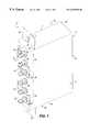
- FIG. 1is a front perspective view of an embodiment of a crossconnect module constructed in accordance with the present invention.
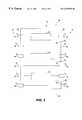
- FIG. 2is a rear perspective view of the crossconnect module shown in FIG. 1 .
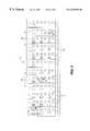
- FIG. 3is a schematic diagram of the crossconnect module shown in FIGS. 1 and 2.
- FIG. 4is a schematic view of a bay panel provided with a plurality of the crossconnect modules shown in FIG. 1-3.
- FIGS. 1 and 2illustrate an embodiment of a crossconnect module 10 constructed in accordance with the present invention.
- the crossconnect module 10comprises a housing 12 that typically is constructed of a sheet metal material.
- the housing 12generally comprises a front side 14 , a rear side 16 , a top side 18 , a bottom side 20 , and opposed lateral sides 22 and 24 .
- Each of these sidesnormally includes a panel.
- the front side 14includes a front panel 26
- the rear side 16includes a rear panel 28
- the top side 18includes a top panel 30
- the bottom side 20includes a bottom panel 32 .
- mounting flanges 34Extending outwardly from the top and bottom panels 30 and 32 are mounting flanges 34 . These mounting flanges 34 are used to mount the bay module 10 into a bay panel (see FIG. 4 ). This mounting is facilitated with mounting fasteners 36 which extend through the mounting flanges 34 . Typically, these mounting fasteners 36 comprise plastic quick-release fasteners, which are well known fasteners.
- a plurality of fiber optic connectorsare mounted in the front panel 26 of the module 10 .
- the front panel 26includes a plurality of circuit connectors 38 and monitoring connectors 40 .
- the circuit connectors 38are arranged linearly in a row that extends from the top side 18 to the bottom side 20 of the crossconnect module 10 .
- the circuit connectors 38are arranged in pairs 42 which each comprises a transmitting connector 44 and a receiving connector 46 .
- each of the circuit connectors 38can comprise an SC connector presently available from Lucent Technologies Inc.
- each of the monitoring connectors 40can comprise LC connectors also currently available from Lucent Technologies Inc.
- the rear panel 28similarly is provided with a plurality of circuit connectors 38 .
- these circuit connectors 38are arranged linearly in a row that extends from the top side 18 to the bottom side 20 of the crossconnect module 10 .
- these connectors 38are arranged in a plurality of pairs 48 that each comprises a transmitting connector 44 and a receiving connector 46 .
- the circuit connectors mounted in the rear panel 28normally comprise SC connectors.
- FIG. 3a fiber connection schematic diagram of the crossconnect module 10 is illustrated.
- the crossconnect module 10is represented in a side view with the front side 14 of the module located to the right in the drawing and the rear side 16 of the module located to the left in the drawing.
- the transmitting and receiving connectors 44 and 46are provided with the designation T and R, respectively.
- the different pairs of circuit connectorsare provided with numerical designations to identify them as each pertaining to one of three pairs on each side of the module 10 . Accordingly, for example, the top two circuit connectors on both sides of the crossconnect module 10 are identified as T 1 and R 1 , respectively.
- the receiving connectors 46 of the front and rear sides 14 and 16are directly connected to each other through the crossconnect module 10 .
- an optical beam splitter 50that divides the signal travelling between the connectors into two paths.
- One portion of the split signal transmitted from the rear side transmitting connector 44is directed to the front side transmitting connector 44 , while the other portion of the split signal is diverted to one of the monitoring connectors 40 mounted within the front panel 26 .
- One such monitoring connector 40is connected to each beam splitter 50 such that a portion of each transmit, or output, signal is diverted to one of the monitoring connectors.
- 90% of the output signalis transmitted uninterrupted between the transmitting connectors 44 , while 10% of the signal is diverted to the associated monitoring connector 40 . So arranged, the output signals travelling from one transmitting connector 44 to another can be monitored with an appropriate monitoring device (not shown) without appreciably disrupting the signal.
- the crossconnect module 10can be used to facilitate monitoring of an output signal transmitted from one fiber optic cable to another.
- a techniciancan simply run a jumper cable from an appropriate monitoring device to the particular monitoring connector 40 associated with the particular circuit that is to be tested.
- optical beam splitters 50are integrated into the crossconnect module 10 , interruption of the transmission signal is unnecessary.
- the connection of a multiplicity of jumper cablesis not needed, thereby greatly simplifying the evaluation procedure so that an accurate assessment can be made by a technician.
- each connection point along a transmission pathcan be evaluated in this manner to determine where along the path the problem is occurring.
- FIG. 4schematically illustrates a single bay panel 52 provided with a plurality of crossconnect modules 10 such as those shown in FIGS. 1-3 and described in the foregoing paragraphs.
- each station 54 of the panel 52can house a crossconnect module 10 such that every circuit within the panel can be non-intrusively monitored in the manner described hereinbefore. Accordingly, with the arrangement shown in FIG. 4, monitoring of every panel circuit can be effected in a passive, non-intrusive manner so that problem areas can be isolated without interrupting transmissions to the customer.
- the crossconnect modules 10are adapted for direct installation into the standard bay panels 52 , existing bay panels can be retrofitted with the crossconnect modules 10 so that additional panel space need not be occupied by separate monitoring devices. Accordingly, with the crossconnect module 10 of the present invention, the optical fiber density of existing networks can be maintained while also providing signal monitoring capability.
- 12 such crossconnect modules 10can be installed within a standard panel such as an LGX crossconnect panel currently available from Lucent Technologies Inc. In such an arrangement, the connection of 36 different circuits can be facilitated as well as monitored as desired.
Landscapes
- Physics & Mathematics (AREA)
- General Physics & Mathematics (AREA)
- Optics & Photonics (AREA)
- Light Guides In General And Applications Therefor (AREA)
Abstract
Description
The present invention generally relates to a crossconnect module having monitoring provisions. More particularly, the present invention relates to a non-intrusive, passive crossconnect module that provides for transmission signal monitoring and which can be installed in a standard bay panel.
Fiber optic peripheral equipment for cable management, cable storage, and connection capabilities are well known. Typically, this cable management, storage and connection is facilitated in bays that comprise a plurality of stacked shelves in which fiber optic crossconnect panels are installed. Within each panel is a plurality of stations that are adapted to receive crossconnect modules that facilitate the various optical fiber connections. Each module normally comprises a plurality of “patch throughs” that merely consist of a plurality of connectors installed in a panel that are used to connect two optical fiber connectors so that the pieces of equipment connected to these fibers can transmit and receive signals to and from each other. Several such connections may be made between a transmitter, e.g. a core network, of the signal and the receiver, e.g. a customer premise.
With the multiplicity of fiber optical connections made along any given transmission path, several transmission problems can arise. One problem involves locating a fault point in situations where transmission losses are occurring. For example, if a customer notifies a signal provider that a signal being transmitted to the customer is not arriving or is being corrupted in some manner, the provider normally must determine where along the transmission path the problem is arising. This typically requires checking the output of each connection point along the transmission path to ensure that an uncorrupted signal is being sent from each connection point. In this manner, the problem area along the transmission path can be isolated and the problem remedied.
Separate monitoring devices are usually used to evaluate the output signals to check their integrity. To conduct such an evaluation, the circuit in which the signal is being transmitted normally must be interrupted and several jumper cables attached between the connection point and the monitoring device. At this point, a diagnostic test can be performed to judge transmission performance. Although effective in identifying the problem area, this method is disruptive because the customer's signal must first be interrupted when connecting the device. In addition, this method creates difficulty in that, due to the several jumper connections presently required, it is easy for the technician to confuse the various jumpers and connectors and, therefore, make an erroneous assessment of the transmission performance based upon the wrong signal. Moreover, the customer often must incur additional expense to provide for additional equipment space (e.g., panel space or floor space) for the devices used to check the signals.
From the foregoing, it can be appreciated that it would be desirable to have a monitoring point that is integrated into transmission circuits so that signal interruption and technician confusion can be avoided. Furthermore, it would be desirable to have such a monitoring point integrated into crossconnect panels so that no fiber optic density is lost through the provision of the monitoring point.
The present disclosure relates to a crossconnect module that comprises a housing adapted for mounting within a crossconnect panel. In one embodiment, the module includes first and second transmitting connectors connected to each other with a first transmission path and first and second receiving connectors connected to each other with a second transmission path. Further included is a monitoring connector, a signal splitter disposed within the housing along one of the first and second transmission paths, and a third transmission path extending from the signal splitter to the monitoring connector.
In use, a portion of a signal transmitted along one of the first and second transmission paths is diverted by the signal splitter to the third transmission path so that the diverted portion of the signal can be monitored with a monitoring device that can, for example, comprise a conventional monitoring device via the monitoring connector to determine whether a uncorrupted signal is being sent through the module. In one arrangement, the signal splitter is disposed along the first transmission path such that the monitored signal is an output signal.
The features and advantages of the invention will become apparent upon reading the following specification, when taken in conjunction with the accompanying drawings.
The invention can be better understood with reference to the following drawings. The components in the drawings are not necessarily to scale, emphasis instead being placed upon clearly illustrating the principles of the present invention.
FIG. 1 is a front perspective view of an embodiment of a crossconnect module constructed in accordance with the present invention.
FIG. 2 is a rear perspective view of the crossconnect module shown in FIG.1.
FIG. 3 is a schematic diagram of the crossconnect module shown in FIGS. 1 and 2.
FIG. 4 is a schematic view of a bay panel provided with a plurality of the crossconnect modules shown in FIG. 1-3.
Referring now in more detail to the drawings, in which like numerals indicate corresponding parts throughout the several views, FIGS. 1 and 2 illustrate an embodiment of acrossconnect module 10 constructed in accordance with the present invention. As is shown in these figures, thecrossconnect module 10 comprises ahousing 12 that typically is constructed of a sheet metal material. Thehousing 12 generally comprises afront side 14, arear side 16, atop side 18, abottom side 20, and opposedlateral sides front side 14 includes afront panel 26, therear side 16 includes arear panel 28, thetop side 18 includes atop panel 30, and thebottom side 20 includes abottom panel 32. Extending outwardly from the top andbottom panels flanges 34. Thesemounting flanges 34 are used to mount thebay module 10 into a bay panel (see FIG.4). This mounting is facilitated withmounting fasteners 36 which extend through themounting flanges 34. Typically, thesemounting fasteners 36 comprise plastic quick-release fasteners, which are well known fasteners.
As indicated in FIG. 1, a plurality of fiber optic connectors are mounted in thefront panel 26 of themodule 10. More specifically, thefront panel 26 includes a plurality ofcircuit connectors 38 andmonitoring connectors 40. In the example embodiment disclosed herein, thecircuit connectors 38 are arranged linearly in a row that extends from thetop side 18 to thebottom side 20 of thecrossconnect module 10. As will be discussed hereinafter, thecircuit connectors 38 are arranged inpairs 42 which each comprises atransmitting connector 44 and areceiving connector 46. By way of example, each of thecircuit connectors 38 can comprise an SC connector presently available from Lucent Technologies Inc. By further way of example, each of themonitoring connectors 40 can comprise LC connectors also currently available from Lucent Technologies Inc.
As is illustrated in FIG. 2, therear panel 28 similarly is provided with a plurality ofcircuit connectors 38. Again, thesecircuit connectors 38 are arranged linearly in a row that extends from thetop side 18 to thebottom side 20 of thecrossconnect module 10. In addition, theseconnectors 38 are arranged in a plurality ofpairs 48 that each comprises atransmitting connector 44 and areceiving connector 46. Similar to thecircuit connectors 38 provided on thefront panel 26, the circuit connectors mounted in therear panel 28 normally comprise SC connectors.
With reference to FIG. 3, a fiber connection schematic diagram of thecrossconnect module 10 is illustrated. In this figure, thecrossconnect module 10 is represented in a side view with thefront side 14 of the module located to the right in the drawing and therear side 16 of the module located to the left in the drawing. As is indicated in this figure, the transmitting and receivingconnectors module 10. Accordingly, for example, the top two circuit connectors on both sides of thecrossconnect module 10 are identified as T1and R1, respectively. As shown in the schematic, thereceiving connectors 46 of the front andrear sides crossconnect module 10. However, in between each linked pair of transmittingconnectors 44 is anoptical beam splitter 50 that divides the signal travelling between the connectors into two paths. One portion of the split signal transmitted from the rearside transmitting connector 44 is directed to the frontside transmitting connector 44, while the other portion of the split signal is diverted to one of themonitoring connectors 40 mounted within thefront panel 26. Onesuch monitoring connector 40 is connected to eachbeam splitter 50 such that a portion of each transmit, or output, signal is diverted to one of the monitoring connectors. In one embodiment, 90% of the output signal is transmitted uninterrupted between the transmittingconnectors 44, while 10% of the signal is diverted to the associatedmonitoring connector 40. So arranged, the output signals travelling from one transmittingconnector 44 to another can be monitored with an appropriate monitoring device (not shown) without appreciably disrupting the signal.
The primary components of theconnector module 10 having been described in the foregoing, operation of thecrossconnect module 10 will now be discussed. In use, thecrossconnect module 10 can be used to facilitate monitoring of an output signal transmitted from one fiber optic cable to another. To effect evaluation of this output signal, a technician can simply run a jumper cable from an appropriate monitoring device to theparticular monitoring connector 40 associated with the particular circuit that is to be tested. In thatoptical beam splitters 50 are integrated into thecrossconnect module 10, interruption of the transmission signal is unnecessary. In addition, because of this integration, the connection of a multiplicity of jumper cables is not needed, thereby greatly simplifying the evaluation procedure so that an accurate assessment can be made by a technician. In a scenario in which, for example, a customer reports a loss of signal or data corruption, each connection point along a transmission path can be evaluated in this manner to determine where along the path the problem is occurring.
FIG. 4 schematically illustrates asingle bay panel 52 provided with a plurality ofcrossconnect modules 10 such as those shown in FIGS. 1-3 and described in the foregoing paragraphs. As is illustrated in this figure, eachstation 54 of thepanel 52 can house acrossconnect module 10 such that every circuit within the panel can be non-intrusively monitored in the manner described hereinbefore. Accordingly, with the arrangement shown in FIG. 4, monitoring of every panel circuit can be effected in a passive, non-intrusive manner so that problem areas can be isolated without interrupting transmissions to the customer. In that, as illustrated in this figure, thecrossconnect modules 10 are adapted for direct installation into thestandard bay panels 52, existing bay panels can be retrofitted with thecrossconnect modules 10 so that additional panel space need not be occupied by separate monitoring devices. Accordingly, with thecrossconnect module 10 of the present invention, the optical fiber density of existing networks can be maintained while also providing signal monitoring capability. By way of example, 12such crossconnect modules 10 can be installed within a standard panel such as an LGX crossconnect panel currently available from Lucent Technologies Inc. In such an arrangement, the connection of36 different circuits can be facilitated as well as monitored as desired.
While particular embodiments of the invention have been disclosed in detail in the foregoing description and drawings, it will be understood by those skilled in the art that variations and modifications thereof can be made without departing from the spirit and scope of the invention as set forth in the following claims. In particular, while certain types of components and certain numbers of such components are identified herein by way of example, it is to be appreciated that alternative types and numbers of such components could be used with equally successful results.
Claims (10)
1. A crossconnect module, comprising:
a housing adapted for mounting within a crossconnect panel;
pairs of first and second transmitting connectors mounted to said housing, each pair of first and second transmitting connectors being connected to each other via first transmission paths that extend between said transmitting connectors within said housing;
pairs of first and second receiving connectors mounted to said housing, each pair of first and second receiving connectors being connected to each other via second transmission paths that extend between said receiving connectors within said housing;
monitoring connectors mounted to said housing;
signal splitters disposed within said housing, one signal splitter disposed along each of said first transmission paths; and
third transmission paths extending from said signal splitters to said monitoring connectors;
wherein a portion of a signal transmitted along each one of said first transmission paths is diverted by one of said signal splitters to one of said third transmission paths so that the diverted portion of the signal is monitorable by connecting a monitoring device to one of said monitoring connectors.
2. The module of claim1, wherein said first transmitting connectors are located on a front side of said housing and said second transmitting connectors are located on a rear side of said housing.
3. The module of claim1, wherein said first receiving connectors are located on a front side of said housing and said second receiving connectors are located on a rear side of said housing.
4. The module of claim1, wherein said monitoring connectors are located on a front side of said housing.
5. The module of claim1, wherein the signal splitters divert approximately 10% of the signals to the monitoring connectors.
6. The module of claim1, wherein said housing comprises at least one mounting flange that includes a fastener with which said module is mountable within the panel.
7. A crossconnect panel, comprising:
a plurality of panel stations each adapted to receive a crossconnect module; and
at least one crossconnect module housed within one of said panel stations, the module including
a housing,
first and second transmitting connectors mounted to said housing and being connected to each other via a first transmission path,
first and second receiving connectors mounted to said housing and being connected to each other via a second transmission path,
a monitoring connector mounted to said housing,
a signal splitter disposed within said housing along one of said first and second transmission paths; and
a third transmission path extending from said signal splitter to said monitoring connector.
8. The module of claim7, wherein said signal splitter is disposed along said first transmission path.
9. A method of monitoring a transmission signal, comprising the steps of:
providing a crossconnect module having multiple circuits that carry multiple output signals and a signal splitting device for each circuit;
arranging the crossconnect module such that a portion of each output signal transmitted through the module is diverted by a signal splitting device to one of multiple monitoring connectors of the crossconnect module;
inserting the crossconnect module in a crossconnect panel; and
transmitting multiple output signals through said module and monitoring these signals via the monitoring connectors.
10. The method of claim9, wherein the crossconnect module is arranged so that an output signal is diverted by the signal splitting device.
Priority Applications (1)
| Application Number | Priority Date | Filing Date | Title |
|---|---|---|---|
| US09/426,606US6259850B1 (en) | 1999-10-26 | 1999-10-26 | Crossconnect module having monitoring provisions |
Applications Claiming Priority (1)
| Application Number | Priority Date | Filing Date | Title |
|---|---|---|---|
| US09/426,606US6259850B1 (en) | 1999-10-26 | 1999-10-26 | Crossconnect module having monitoring provisions |
Publications (1)
| Publication Number | Publication Date |
|---|---|
| US6259850B1true US6259850B1 (en) | 2001-07-10 |
Family
ID=23691474
Family Applications (1)
| Application Number | Title | Priority Date | Filing Date |
|---|---|---|---|
| US09/426,606Expired - Fee RelatedUS6259850B1 (en) | 1999-10-26 | 1999-10-26 | Crossconnect module having monitoring provisions |
Country Status (1)
| Country | Link |
|---|---|
| US (1) | US6259850B1 (en) |
Cited By (39)
| Publication number | Priority date | Publication date | Assignee | Title |
|---|---|---|---|---|
| US6355886B1 (en)* | 1999-05-21 | 2002-03-12 | Tycom (Us) Inc. | Undersea trunk-and-branch logical ring networks |
| US6634794B1 (en) | 2002-06-05 | 2003-10-21 | Lucent Technologies Inc. | Optical fiber connector assembly |
| US20040109660A1 (en)* | 2002-12-05 | 2004-06-10 | Jonathan Liberty | High density fiber optic module |
| US20040112623A1 (en)* | 2002-09-26 | 2004-06-17 | L'henaff Jean-Jacques | Electronics housing and associated connectors for cable/wiring distribution system |
| US20050002633A1 (en)* | 2003-07-02 | 2005-01-06 | Solheid James J. | Telecommunications connection cabinet |
| US20050281526A1 (en)* | 2004-06-18 | 2005-12-22 | Soutsada Vongseng | Multi-position fiber optic connector holder and method |
| US7407330B2 (en) | 2003-06-30 | 2008-08-05 | Adc Telecommunications, Inc. | Fiber optic connector holder and method |
| US20090263096A1 (en)* | 2007-11-21 | 2009-10-22 | Adc Telecommunications, Inc. | Fiber distribution hub with multiple configurations |
| US7941026B2 (en) | 2005-03-31 | 2011-05-10 | Adc Telecommunications, Inc. | Adapter block including connector storage |
| US8382382B2 (en) | 2008-08-27 | 2013-02-26 | Adc Telecommunications, Inc. | Fiber optic adapter with integrally molded ferrule alignment structure |
| WO2013173536A1 (en)* | 2012-05-16 | 2013-11-21 | Corning Cable Systems Llc | High-density port tap fiber optic modules, and related systems and methods for monitoring optical networks |
| USRE44758E1 (en) | 2003-03-20 | 2014-02-11 | Adc Telecommunications, Inc. | Optical fiber interconnect cabinets, termination modules and fiber connectivity management for the same |
| CN103760648A (en)* | 2013-12-31 | 2014-04-30 | Tcl-罗格朗国际电工(惠州)有限公司 | Optical branching unit and optical branching module thereof |
| US8879881B2 (en) | 2010-04-30 | 2014-11-04 | Corning Cable Systems Llc | Rotatable routing guide and assembly |
| US8913866B2 (en) | 2010-03-26 | 2014-12-16 | Corning Cable Systems Llc | Movable adapter panel |
| US8953924B2 (en) | 2011-09-02 | 2015-02-10 | Corning Cable Systems Llc | Removable strain relief brackets for securing fiber optic cables and/or optical fibers to fiber optic equipment, and related assemblies and methods |
| US8965168B2 (en) | 2010-04-30 | 2015-02-24 | Corning Cable Systems Llc | Fiber management devices for fiber optic housings, and related components and methods |
| US8985862B2 (en) | 2013-02-28 | 2015-03-24 | Corning Cable Systems Llc | High-density multi-fiber adapter housings |
| US8989547B2 (en) | 2011-06-30 | 2015-03-24 | Corning Cable Systems Llc | Fiber optic equipment assemblies employing non-U-width-sized housings and related methods |
| US8992099B2 (en) | 2010-02-04 | 2015-03-31 | Corning Cable Systems Llc | Optical interface cards, assemblies, and related methods, suited for installation and use in antenna system equipment |
| US8995812B2 (en) | 2012-10-26 | 2015-03-31 | Ccs Technology, Inc. | Fiber optic management unit and fiber optic distribution device |
| US9008485B2 (en) | 2011-05-09 | 2015-04-14 | Corning Cable Systems Llc | Attachment mechanisms employed to attach a rear housing section to a fiber optic housing, and related assemblies and methods |
| US9020320B2 (en) | 2008-08-29 | 2015-04-28 | Corning Cable Systems Llc | High density and bandwidth fiber optic apparatuses and related equipment and methods |
| US9022814B2 (en) | 2010-04-16 | 2015-05-05 | Ccs Technology, Inc. | Sealing and strain relief device for data cables |
| US9042702B2 (en) | 2012-09-18 | 2015-05-26 | Corning Cable Systems Llc | Platforms and systems for fiber optic cable attachment |
| US9038832B2 (en) | 2011-11-30 | 2015-05-26 | Corning Cable Systems Llc | Adapter panel support assembly |
| US9075217B2 (en) | 2010-04-30 | 2015-07-07 | Corning Cable Systems Llc | Apparatuses and related components and methods for expanding capacity of fiber optic housings |
| US9146362B2 (en) | 2012-09-21 | 2015-09-29 | Adc Telecommunications, Inc. | Insertion and removal tool for a fiber optic ferrule alignment sleeve |
| US9213161B2 (en) | 2010-11-05 | 2015-12-15 | Corning Cable Systems Llc | Fiber body holder and strain relief device |
| US9250409B2 (en) | 2012-07-02 | 2016-02-02 | Corning Cable Systems Llc | Fiber-optic-module trays and drawers for fiber-optic equipment |
| US9279951B2 (en) | 2010-10-27 | 2016-03-08 | Corning Cable Systems Llc | Fiber optic module for limited space applications having a partially sealed module sub-assembly |
| US9519118B2 (en) | 2010-04-30 | 2016-12-13 | Corning Optical Communications LLC | Removable fiber management sections for fiber optic housings, and related components and methods |
| US9645317B2 (en) | 2011-02-02 | 2017-05-09 | Corning Optical Communications LLC | Optical backplane extension modules, and related assemblies suitable for establishing optical connections to information processing modules disposed in equipment racks |
| US9885845B2 (en)* | 2015-01-15 | 2018-02-06 | Commscope, Inc. Of North Carolina | Module and assembly for fiber optic interconnections |
| US10067309B2 (en) | 1999-03-01 | 2018-09-04 | Commscope Technologies Llc | Optical fiber distribution frame with outside plant enclosure |
| US10094996B2 (en) | 2008-08-29 | 2018-10-09 | Corning Optical Communications, Llc | Independently translatable modules and fiber optic equipment trays in fiber optic equipment |
| US10302874B2 (en) | 2015-05-15 | 2019-05-28 | Commscope Telecommunications (Shanghai) Co., Ltd. | Alignment sleeve assembly and fiber optic adapter |
| US10393980B2 (en) | 2003-11-17 | 2019-08-27 | Commscope Technologies Llc | Fiber distribution device |
| US11294135B2 (en) | 2008-08-29 | 2022-04-05 | Corning Optical Communications LLC | High density and bandwidth fiber optic apparatuses and related equipment and methods |
Citations (3)
| Publication number | Priority date | Publication date | Assignee | Title |
|---|---|---|---|---|
| US5231687A (en)* | 1990-06-04 | 1993-07-27 | Bicc Plc | Termination system for optical fibres |
| US5432875A (en) | 1993-02-19 | 1995-07-11 | Adc Telecommunications, Inc. | Fiber optic monitor module |
| US5774245A (en) | 1996-07-08 | 1998-06-30 | Worldcom Network Services, Inc. | Optical cross-connect module |
- 1999
- 1999-10-26USUS09/426,606patent/US6259850B1/ennot_activeExpired - Fee Related
Patent Citations (3)
| Publication number | Priority date | Publication date | Assignee | Title |
|---|---|---|---|---|
| US5231687A (en)* | 1990-06-04 | 1993-07-27 | Bicc Plc | Termination system for optical fibres |
| US5432875A (en) | 1993-02-19 | 1995-07-11 | Adc Telecommunications, Inc. | Fiber optic monitor module |
| US5774245A (en) | 1996-07-08 | 1998-06-30 | Worldcom Network Services, Inc. | Optical cross-connect module |
Cited By (131)
| Publication number | Priority date | Publication date | Assignee | Title |
|---|---|---|---|---|
| US10067309B2 (en) | 1999-03-01 | 2018-09-04 | Commscope Technologies Llc | Optical fiber distribution frame with outside plant enclosure |
| US6355886B1 (en)* | 1999-05-21 | 2002-03-12 | Tycom (Us) Inc. | Undersea trunk-and-branch logical ring networks |
| US6634794B1 (en) | 2002-06-05 | 2003-10-21 | Lucent Technologies Inc. | Optical fiber connector assembly |
| US20040112623A1 (en)* | 2002-09-26 | 2004-06-17 | L'henaff Jean-Jacques | Electronics housing and associated connectors for cable/wiring distribution system |
| US6953895B2 (en)* | 2002-09-26 | 2005-10-11 | Terk Technologies Corporation | Electronics housings and associated connectors for cable/wiring distribution system |
| US20060005985A1 (en)* | 2002-09-26 | 2006-01-12 | L Henaff Jean-Jacques | Electronics housings and associated connectors for cable/wiring distribution system |
| US20040109660A1 (en)* | 2002-12-05 | 2004-06-10 | Jonathan Liberty | High density fiber optic module |
| US6768860B2 (en)* | 2002-12-05 | 2004-07-27 | Jds Uniphase Inc. | High density fiber optic module |
| USRE48675E1 (en) | 2003-03-20 | 2021-08-10 | Commscope Technologies Llc | Optical fiber interconnect cabinets, termination modules and fiber connectivity management for the same |
| USRE44758E1 (en) | 2003-03-20 | 2014-02-11 | Adc Telecommunications, Inc. | Optical fiber interconnect cabinets, termination modules and fiber connectivity management for the same |
| USRE46945E1 (en) | 2003-03-20 | 2018-07-10 | Commscope Technologies Llc | Optical fiber interconnect cabinets, termination modules and fiber connectivity management for the same |
| US7980768B2 (en) | 2003-06-30 | 2011-07-19 | Adc Telecommunications, Inc. | Fiber optic connector holder and method |
| US10168491B2 (en) | 2003-06-30 | 2019-01-01 | Commscope Technologies Llc | Fiber optic connector holder and method |
| US9122019B2 (en) | 2003-06-30 | 2015-09-01 | Adc Telecommunications, Inc. | Fiber optic connector holder and method |
| US8636421B2 (en) | 2003-06-30 | 2014-01-28 | Adc Telecommunications, Inc. | Fiber optic connector holder and method |
| US7407330B2 (en) | 2003-06-30 | 2008-08-05 | Adc Telecommunications, Inc. | Fiber optic connector holder and method |
| US9470851B2 (en) | 2003-06-30 | 2016-10-18 | Commscope Technologies Llc | Fiber optic connector holder and method |
| US10634860B2 (en) | 2003-06-30 | 2020-04-28 | Commscope Technologies Llc | Fiber optic connector holder and method |
| US8210756B2 (en) | 2003-06-30 | 2012-07-03 | Adc Telecommunications, Inc. | Fiber optic connector holder and method |
| US20090087157A1 (en)* | 2003-06-30 | 2009-04-02 | Adc Telecommunications, Inc. | Fiber optic connector holder and method |
| US9784928B2 (en) | 2003-06-30 | 2017-10-10 | Commscope Technologies Llc | Fiber optic connector holder and method |
| US20110033158A1 (en)* | 2003-06-30 | 2011-02-10 | Adc Telecommunications, Inc. | Fiber optic connector holder and method |
| US11119285B2 (en) | 2003-06-30 | 2021-09-14 | Commscope Technologies Llc | Fiber optic connector holder and method |
| US7841775B2 (en) | 2003-06-30 | 2010-11-30 | Adc Telecommunications, Inc. | Connector storage system |
| US10527809B2 (en) | 2003-07-02 | 2020-01-07 | Commscope Technologies Llc | Telecommunications connection cabinet |
| US9304276B2 (en) | 2003-07-02 | 2016-04-05 | Commscope Technologies Llc | Telecommunications connection cabinet |
| US10151896B2 (en) | 2003-07-02 | 2018-12-11 | CommScope Technologies, LLC | Telecommunications connection cabinet |
| US10371915B2 (en) | 2003-07-02 | 2019-08-06 | Commscope Technologies Llc | Telecommunications connection cabinet |
| US7844159B2 (en) | 2003-07-02 | 2010-11-30 | Adc Telecommunications, Inc. | Telecommunications connection cabinet |
| US10782497B2 (en) | 2003-07-02 | 2020-09-22 | Commscope Technologies Llc | Telecommunications connection cabinet |
| US10436998B2 (en) | 2003-07-02 | 2019-10-08 | Commscope Technologies Llc | Telecommunications connection cabinet |
| US20110033164A1 (en)* | 2003-07-02 | 2011-02-10 | Adc Telecommunications, Inc. | Telecommunications connection cabinet |
| US20050002633A1 (en)* | 2003-07-02 | 2005-01-06 | Solheid James J. | Telecommunications connection cabinet |
| US8811791B2 (en) | 2003-07-02 | 2014-08-19 | Adc Telecommunications, Inc. | Telecommunications connection cabinet |
| US7995894B2 (en) | 2003-07-02 | 2011-08-09 | Adc Telecommunications, Inc. | Telecommunications connection cabinet |
| US20080075411A1 (en)* | 2003-07-02 | 2008-03-27 | Adc Telecommunications, Inc. | Telecommunications connection cabinet |
| US20090074372A1 (en)* | 2003-07-02 | 2009-03-19 | Adc Telecommunications, Inc. | Telecommunications connection cabinet |
| US9541724B2 (en) | 2003-07-02 | 2017-01-10 | Commscope Technologies Llc | Telecommunications connection cabinet |
| US7457503B2 (en) | 2003-07-02 | 2008-11-25 | Adc Telecommunications, Inc. | Telecommunications connection cabinet |
| US8401357B2 (en) | 2003-07-02 | 2013-03-19 | Adc Telecommunications, Inc. | Telecommunications connection cabinet |
| US7233731B2 (en) | 2003-07-02 | 2007-06-19 | Adc Telecommunications, Inc. | Telecommunications connection cabinet |
| US9250408B2 (en) | 2003-07-02 | 2016-02-02 | Commscope Technologies Llc | Telecommunications connection cabinet |
| US10782498B2 (en) | 2003-11-17 | 2020-09-22 | Commscope Technologies Llc | Fiber distribution device |
| US11579390B2 (en) | 2003-11-17 | 2023-02-14 | Commscope Technologies Llc | Fiber distribution device |
| US10393980B2 (en) | 2003-11-17 | 2019-08-27 | Commscope Technologies Llc | Fiber distribution device |
| US10345539B2 (en) | 2004-06-18 | 2019-07-09 | Commscope Technologies Llc | Telecommunications cabinet with connector storage |
| US7519259B2 (en) | 2004-06-18 | 2009-04-14 | Adc Telecommunications, Inc. | Increasing capacity of a telecommunications cabinet |
| US8184940B2 (en) | 2004-06-18 | 2012-05-22 | Adc Telecommunications, Inc. | Telecommunications cabinet with connector storage |
| US20110019965A1 (en)* | 2004-06-18 | 2011-01-27 | Adc Telecommunications, Inc. | Telecommunications cabinet with connector storage |
| US20050281526A1 (en)* | 2004-06-18 | 2005-12-22 | Soutsada Vongseng | Multi-position fiber optic connector holder and method |
| US10126509B2 (en) | 2004-06-18 | 2018-11-13 | Commscope Technologies Llc | Telecommunications cabinet with connector storage |
| US11428876B2 (en) | 2004-06-18 | 2022-08-30 | Commscope Technologies Llc | Telecommunications cabinet with connector storage |
| US7826706B2 (en) | 2004-06-18 | 2010-11-02 | Adc Telecommunications, Inc. | Telecommunications connection cabinet |
| US7218827B2 (en) | 2004-06-18 | 2007-05-15 | Adc Telecommunications, Inc. | Multi-position fiber optic connector holder and method |
| US7277620B2 (en) | 2004-06-18 | 2007-10-02 | Adc Telecommunications, Inc. | Fiber optic splitter |
| US10809467B2 (en) | 2004-06-18 | 2020-10-20 | Commscope Technologies Llc | Telecommunications cabinet with connector storage |
| US9341798B2 (en) | 2004-06-18 | 2016-05-17 | Commscope Technologies Llc | Telecommunications cabinet with connector storage |
| US8538228B2 (en) | 2004-06-18 | 2013-09-17 | Adc Telecommunications, Inc. | Telecommunications cabinet with connector storage |
| US20080019655A1 (en)* | 2004-06-18 | 2008-01-24 | Adc Telecommunications, Inc. | Fiber Optic Splitter |
| US20080025684A1 (en)* | 2004-06-18 | 2008-01-31 | Adc Telecommunications, Inc. | Fiber Optic Splitter |
| US20080317425A1 (en)* | 2004-06-18 | 2008-12-25 | Adc Telecommunications, Inc. | Telecommunications cabinet with connector storage |
| US10634859B2 (en) | 2004-06-18 | 2020-04-28 | Commscope Technologies Llc | Fiber optic connector holder unit |
| US8818158B2 (en) | 2004-06-18 | 2014-08-26 | Adc Telecommunications, Inc. | Telecommunications cabinet with connector storage |
| US7515805B2 (en) | 2004-06-18 | 2009-04-07 | Adc Telecommunications, Inc. | Fiber optic splitter |
| US7809233B2 (en) | 2004-06-18 | 2010-10-05 | Adc Telecommunications, Inc. | Telecommunications cabinet with connector storage |
| US20090196565A1 (en)* | 2004-06-18 | 2009-08-06 | Adc Telecommunications, Inc. | Telecommunications Connection Cabinet |
| US10274686B2 (en) | 2004-06-18 | 2019-04-30 | Commscope Technologies Llc | Telecommunications cabinet with connector storage |
| US9201206B2 (en) | 2004-06-18 | 2015-12-01 | Commscope Emea Limited | Telecommunications cabinet with connector storage |
| US7809234B2 (en) | 2004-06-18 | 2010-10-05 | Adc Telecommunications, Inc. | Telecommunications cabinet with connector storage |
| US7941026B2 (en) | 2005-03-31 | 2011-05-10 | Adc Telecommunications, Inc. | Adapter block including connector storage |
| US20090263096A1 (en)* | 2007-11-21 | 2009-10-22 | Adc Telecommunications, Inc. | Fiber distribution hub with multiple configurations |
| US8229265B2 (en) | 2007-11-21 | 2012-07-24 | Adc Telecommunications, Inc. | Fiber distribution hub with multiple configurations |
| US8992095B2 (en) | 2008-08-27 | 2015-03-31 | Adc Telecommunications, Inc. | Fiber optic adapter with integrally molded ferrule alignment structure |
| US10795090B2 (en) | 2008-08-27 | 2020-10-06 | Commscope Technologies Llc | Fiber optic adapter with integrally molded ferrule alignment structure |
| US9354402B2 (en) | 2008-08-27 | 2016-05-31 | Commscope Technologies Llc | Fiber optic adapter with integrally molded ferrule alignment structure |
| US8382382B2 (en) | 2008-08-27 | 2013-02-26 | Adc Telecommunications, Inc. | Fiber optic adapter with integrally molded ferrule alignment structure |
| US11262507B2 (en) | 2008-08-27 | 2022-03-01 | Commscope Technologies Llc | Fiber optic adapter with integrally molded ferrule alignment structure |
| US11567267B2 (en) | 2008-08-27 | 2023-01-31 | Commscope Technologies Llc | Fiber optic adapter with integrally molded ferrule alignment structure |
| US10197741B2 (en) | 2008-08-27 | 2019-02-05 | Commscope Technologies Llc | Fiber optic adapter with integrally molded ferrule alignment structure |
| US12001061B2 (en) | 2008-08-27 | 2024-06-04 | Commscope Technologies Llc | Fiber optic adapter with integrally molded ferrule alignment structure |
| US9778422B2 (en) | 2008-08-27 | 2017-10-03 | Commscope Technologies Llc | Fiber optic adapter with integrally molded ferrule alignment structure |
| US8845205B2 (en) | 2008-08-27 | 2014-09-30 | Adc Telecommunications, Inc. | Fiber optic adapter with integrally molded ferrule alignment structure |
| US10606014B2 (en) | 2008-08-29 | 2020-03-31 | Corning Optical Communications LLC | Independently translatable modules and fiber optic equipment trays in fiber optic equipment |
| US11092767B2 (en) | 2008-08-29 | 2021-08-17 | Corning Optical Communications LLC | High density and bandwidth fiber optic apparatuses and related equipment and methods |
| US12072545B2 (en) | 2008-08-29 | 2024-08-27 | Corning Optical Communications LLC | High density and bandwidth fiber optic apparatuses and related equipment and methods |
| US11754796B2 (en) | 2008-08-29 | 2023-09-12 | Corning Optical Communications LLC | Independently translatable modules and fiber optic equipment trays in fiber optic equipment |
| US11609396B2 (en) | 2008-08-29 | 2023-03-21 | Corning Optical Communications LLC | High density and bandwidth fiber optic apparatuses and related equipment and methods |
| US10094996B2 (en) | 2008-08-29 | 2018-10-09 | Corning Optical Communications, Llc | Independently translatable modules and fiber optic equipment trays in fiber optic equipment |
| US10120153B2 (en) | 2008-08-29 | 2018-11-06 | Corning Optical Communications, Llc | Independently translatable modules and fiber optic equipment trays in fiber optic equipment |
| US11294136B2 (en) | 2008-08-29 | 2022-04-05 | Corning Optical Communications LLC | High density and bandwidth fiber optic apparatuses and related equipment and methods |
| US10126514B2 (en) | 2008-08-29 | 2018-11-13 | Corning Optical Communications, Llc | Independently translatable modules and fiber optic equipment trays in fiber optic equipment |
| US11294135B2 (en) | 2008-08-29 | 2022-04-05 | Corning Optical Communications LLC | High density and bandwidth fiber optic apparatuses and related equipment and methods |
| US9910236B2 (en) | 2008-08-29 | 2018-03-06 | Corning Optical Communications LLC | High density and bandwidth fiber optic apparatuses and related equipment and methods |
| US11086089B2 (en) | 2008-08-29 | 2021-08-10 | Corning Optical Communications LLC | High density and bandwidth fiber optic apparatuses and related equipment and methods |
| US10222570B2 (en) | 2008-08-29 | 2019-03-05 | Corning Optical Communications LLC | Independently translatable modules and fiber optic equipment trays in fiber optic equipment |
| US10852499B2 (en) | 2008-08-29 | 2020-12-01 | Corning Optical Communications LLC | High density and bandwidth fiber optic apparatuses and related equipment and methods |
| US9020320B2 (en) | 2008-08-29 | 2015-04-28 | Corning Cable Systems Llc | High density and bandwidth fiber optic apparatuses and related equipment and methods |
| US10564378B2 (en) | 2008-08-29 | 2020-02-18 | Corning Optical Communications LLC | High density and bandwidth fiber optic apparatuses and related equipment and methods |
| US10459184B2 (en) | 2008-08-29 | 2019-10-29 | Corning Optical Communications LLC | High density and bandwidth fiber optic apparatuses and related equipment and methods |
| US10444456B2 (en) | 2008-08-29 | 2019-10-15 | Corning Optical Communications LLC | High density and bandwidth fiber optic apparatuses and related equipment and methods |
| US10416405B2 (en) | 2008-08-29 | 2019-09-17 | Corning Optical Communications LLC | Independently translatable modules and fiber optic equipment trays in fiber optic equipment |
| US10422971B2 (en) | 2008-08-29 | 2019-09-24 | Corning Optical Communicatinos LLC | High density and bandwidth fiber optic apparatuses and related equipment and methods |
| US8992099B2 (en) | 2010-02-04 | 2015-03-31 | Corning Cable Systems Llc | Optical interface cards, assemblies, and related methods, suited for installation and use in antenna system equipment |
| US8913866B2 (en) | 2010-03-26 | 2014-12-16 | Corning Cable Systems Llc | Movable adapter panel |
| US9022814B2 (en) | 2010-04-16 | 2015-05-05 | Ccs Technology, Inc. | Sealing and strain relief device for data cables |
| US9519118B2 (en) | 2010-04-30 | 2016-12-13 | Corning Optical Communications LLC | Removable fiber management sections for fiber optic housings, and related components and methods |
| US8879881B2 (en) | 2010-04-30 | 2014-11-04 | Corning Cable Systems Llc | Rotatable routing guide and assembly |
| US8965168B2 (en) | 2010-04-30 | 2015-02-24 | Corning Cable Systems Llc | Fiber management devices for fiber optic housings, and related components and methods |
| US9075217B2 (en) | 2010-04-30 | 2015-07-07 | Corning Cable Systems Llc | Apparatuses and related components and methods for expanding capacity of fiber optic housings |
| US9279951B2 (en) | 2010-10-27 | 2016-03-08 | Corning Cable Systems Llc | Fiber optic module for limited space applications having a partially sealed module sub-assembly |
| US9213161B2 (en) | 2010-11-05 | 2015-12-15 | Corning Cable Systems Llc | Fiber body holder and strain relief device |
| US10481335B2 (en) | 2011-02-02 | 2019-11-19 | Corning Optical Communications, Llc | Dense shuttered fiber optic connectors and assemblies suitable for establishing optical connections for optical backplanes in equipment racks |
| US9645317B2 (en) | 2011-02-02 | 2017-05-09 | Corning Optical Communications LLC | Optical backplane extension modules, and related assemblies suitable for establishing optical connections to information processing modules disposed in equipment racks |
| US9008485B2 (en) | 2011-05-09 | 2015-04-14 | Corning Cable Systems Llc | Attachment mechanisms employed to attach a rear housing section to a fiber optic housing, and related assemblies and methods |
| US8989547B2 (en) | 2011-06-30 | 2015-03-24 | Corning Cable Systems Llc | Fiber optic equipment assemblies employing non-U-width-sized housings and related methods |
| US8953924B2 (en) | 2011-09-02 | 2015-02-10 | Corning Cable Systems Llc | Removable strain relief brackets for securing fiber optic cables and/or optical fibers to fiber optic equipment, and related assemblies and methods |
| US9038832B2 (en) | 2011-11-30 | 2015-05-26 | Corning Cable Systems Llc | Adapter panel support assembly |
| CN104487880A (en)* | 2012-05-16 | 2015-04-01 | 康宁光电通信有限责任公司 | High-density port tap fiber optic modules, and related systems and methods for monitoring optical networks |
| CN104471458A (en)* | 2012-05-16 | 2015-03-25 | 康宁光电通信有限责任公司 | Port tapped fiber optic modules and related systems and methods for monitoring optical networks |
| WO2013173536A1 (en)* | 2012-05-16 | 2013-11-21 | Corning Cable Systems Llc | High-density port tap fiber optic modules, and related systems and methods for monitoring optical networks |
| US9250409B2 (en) | 2012-07-02 | 2016-02-02 | Corning Cable Systems Llc | Fiber-optic-module trays and drawers for fiber-optic equipment |
| US9042702B2 (en) | 2012-09-18 | 2015-05-26 | Corning Cable Systems Llc | Platforms and systems for fiber optic cable attachment |
| US9146362B2 (en) | 2012-09-21 | 2015-09-29 | Adc Telecommunications, Inc. | Insertion and removal tool for a fiber optic ferrule alignment sleeve |
| US9915793B2 (en) | 2012-09-21 | 2018-03-13 | Commscope Technologies Llc | Removal tool for a fiber optic ferrule alignment sleeve |
| US8995812B2 (en) | 2012-10-26 | 2015-03-31 | Ccs Technology, Inc. | Fiber optic management unit and fiber optic distribution device |
| US8985862B2 (en) | 2013-02-28 | 2015-03-24 | Corning Cable Systems Llc | High-density multi-fiber adapter housings |
| CN103760648B (en)* | 2013-12-31 | 2016-11-02 | Tcl-罗格朗国际电工(惠州)有限公司 | Optical branching device and light shunt module thereof |
| CN103760648A (en)* | 2013-12-31 | 2014-04-30 | Tcl-罗格朗国际电工(惠州)有限公司 | Optical branching unit and optical branching module thereof |
| US10613285B2 (en) | 2015-01-15 | 2020-04-07 | Commscope, Inc. Of North Carolina | Module and assembly for fiber optic interconnections |
| US9885845B2 (en)* | 2015-01-15 | 2018-02-06 | Commscope, Inc. Of North Carolina | Module and assembly for fiber optic interconnections |
| US10302874B2 (en) | 2015-05-15 | 2019-05-28 | Commscope Telecommunications (Shanghai) Co., Ltd. | Alignment sleeve assembly and fiber optic adapter |
Similar Documents
| Publication | Publication Date | Title |
|---|---|---|
| US6259850B1 (en) | Crossconnect module having monitoring provisions | |
| EP0828356B1 (en) | Optical monitoring and test access interconnection module | |
| US6317535B1 (en) | System and method for testing optical fibers that lead between a telecommunications provider and a customer's premises | |
| US7542672B2 (en) | Optical switching apparatus with optical reflection monitor and reflection monitoring system | |
| JP3009608B2 (en) | Optical fiber distribution frame | |
| CA2200384C (en) | An optical communications system having distributed intelligence | |
| US6583867B1 (en) | System and method for monitoring optical fiber integrity between the telecommunications provider and a customer's premises | |
| US20090257747A1 (en) | Testing a fiber link in a communication system without interrupting service | |
| US5229875A (en) | Fault-tolerant fiber optic coupler/repeater for use in high speed data transmission and the like | |
| US6618522B2 (en) | Active equipment protection methods and apparatus | |
| US6614968B1 (en) | Spare fiber monitoring arrangement | |
| JP6196124B2 (en) | Optical fiber transmission line monitoring system | |
| WO2007095131A2 (en) | Optical fiber loopback test system and method | |
| US20140072297A1 (en) | Optical fiber loopback adapter | |
| US5594581A (en) | Low loss optical transmission/monitoring path selection in redundant equipment terminals | |
| US6842236B1 (en) | Method and device for continuously monitoring an optical transmission path | |
| US6522434B1 (en) | System and method for determining optical loss characteristics of optical fibers in an optical fiber network | |
| US5020152A (en) | Fault tolerant-fiber optic coupler/repeater for use in high speed data transmission and the like | |
| CN217183295U (en) | High-integration-level optical fiber link online monitoring and alarming module | |
| US6757493B1 (en) | Communication link with non-intrusive expansion capability | |
| US6580847B2 (en) | Multistage photonic switch fault isolation | |
| EP1285299B1 (en) | Optical assembly | |
| KR0160805B1 (en) | Optical connector for trouble tracking in the catv system | |
| AU2001294521A1 (en) | Fiber protection and non-intrusive expansion methods and apparatus | |
| CN222192372U (en) | Optical terminal equipment and communication system |
Legal Events
| Date | Code | Title | Description |
|---|---|---|---|
| AS | Assignment | Owner name:LUCENT TECHNOLOGIES INC., NEW JERSEY Free format text:ASSIGNMENT OF ASSIGNORS INTEREST;ASSIGNORS:CROSBY, MARSHALL E.;HERGENRODER, RONALD;REEL/FRAME:010568/0341 Effective date:20000107 | |
| AS | Assignment | Owner name:FITEL USA CORPORATION, GEORGIA Free format text:ASSIGNMENT OF ASSIGNORS INTEREST;ASSIGNOR:LUCENT TECHNOLOGIES INC.;REEL/FRAME:012734/0892 Effective date:20011116 | |
| FPAY | Fee payment | Year of fee payment:4 | |
| SULP | Surcharge for late payment | ||
| FPAY | Fee payment | Year of fee payment:8 | |
| AS | Assignment | Owner name:FURUKAWA ELECTRIC NORTH AMERICA, INC., GEORGIA Free format text:CHANGE OF NAME;ASSIGNOR:FITEL USA CORP.;REEL/FRAME:025521/0684 Effective date:20031218 | |
| REMI | Maintenance fee reminder mailed | ||
| LAPS | Lapse for failure to pay maintenance fees | ||
| STCH | Information on status: patent discontinuation | Free format text:PATENT EXPIRED DUE TO NONPAYMENT OF MAINTENANCE FEES UNDER 37 CFR 1.362 | |
| FP | Lapsed due to failure to pay maintenance fee | Effective date:20130710 |