US6259730B1 - Transmit diversity and reception equalization for radio links - Google Patents
Transmit diversity and reception equalization for radio linksDownload PDFInfo
- Publication number
- US6259730B1 US6259730B1US09/188,563US18856398AUS6259730B1US 6259730 B1US6259730 B1US 6259730B1US 18856398 AUS18856398 AUS 18856398AUS 6259730 B1US6259730 B1US 6259730B1
- Authority
- US
- United States
- Prior art keywords
- signal
- antennas
- equalizer
- transmitted
- base station
- Prior art date
- Legal status (The legal status is an assumption and is not a legal conclusion. Google has not performed a legal analysis and makes no representation as to the accuracy of the status listed.)
- Expired - Lifetime
Links
Images


Classifications
- H—ELECTRICITY
- H04—ELECTRIC COMMUNICATION TECHNIQUE
- H04B—TRANSMISSION
- H04B7/00—Radio transmission systems, i.e. using radiation field
- H04B7/02—Diversity systems; Multi-antenna system, i.e. transmission or reception using multiple antennas
- H04B7/04—Diversity systems; Multi-antenna system, i.e. transmission or reception using multiple antennas using two or more spaced independent antennas
- H04B7/06—Diversity systems; Multi-antenna system, i.e. transmission or reception using multiple antennas using two or more spaced independent antennas at the transmitting station
- H04B7/0613—Diversity systems; Multi-antenna system, i.e. transmission or reception using multiple antennas using two or more spaced independent antennas at the transmitting station using simultaneous transmission
- H04B7/0667—Diversity systems; Multi-antenna system, i.e. transmission or reception using multiple antennas using two or more spaced independent antennas at the transmitting station using simultaneous transmission of delayed versions of same signal
- H04B7/0671—Diversity systems; Multi-antenna system, i.e. transmission or reception using multiple antennas using two or more spaced independent antennas at the transmitting station using simultaneous transmission of delayed versions of same signal using different delays between antennas
- H—ELECTRICITY
- H04—ELECTRIC COMMUNICATION TECHNIQUE
- H04B—TRANSMISSION
- H04B7/00—Radio transmission systems, i.e. using radiation field
- H04B7/24—Radio transmission systems, i.e. using radiation field for communication between two or more posts
- H04B7/26—Radio transmission systems, i.e. using radiation field for communication between two or more posts at least one of which is mobile
- H—ELECTRICITY
- H04—ELECTRIC COMMUNICATION TECHNIQUE
- H04B—TRANSMISSION
- H04B7/00—Radio transmission systems, i.e. using radiation field
- H04B7/02—Diversity systems; Multi-antenna system, i.e. transmission or reception using multiple antennas
- H04B7/10—Polarisation diversity; Directional diversity
- Y—GENERAL TAGGING OF NEW TECHNOLOGICAL DEVELOPMENTS; GENERAL TAGGING OF CROSS-SECTIONAL TECHNOLOGIES SPANNING OVER SEVERAL SECTIONS OF THE IPC; TECHNICAL SUBJECTS COVERED BY FORMER USPC CROSS-REFERENCE ART COLLECTIONS [XRACs] AND DIGESTS
- Y02—TECHNOLOGIES OR APPLICATIONS FOR MITIGATION OR ADAPTATION AGAINST CLIMATE CHANGE
- Y02D—CLIMATE CHANGE MITIGATION TECHNOLOGIES IN INFORMATION AND COMMUNICATION TECHNOLOGIES [ICT], I.E. INFORMATION AND COMMUNICATION TECHNOLOGIES AIMING AT THE REDUCTION OF THEIR OWN ENERGY USE
- Y02D30/00—Reducing energy consumption in communication networks
- Y02D30/70—Reducing energy consumption in communication networks in wireless communication networks
Definitions
- the present inventionrelates to transmit diversity and reception equalization in a mobile communication system for reducing required transmitted power needed to achieve reliable communication.
- duplex radio systemssuch as cellular telephone systems including a forward link and a reverse link
- link balancemust be maintained to ensure overall communication quality.
- reverse link receiver systems at a cellular base stationemploy diversity reception with two or more reception antennas spread 7-10 ⁇ so that fading of mobile station transmission as perceived by the base station can be mitigated.
- multiple antennas and receiver channelsare not feasible for vehicle mounted or hand-held mobile communication devices in which small size and reduced cost are important. Since vehicle mounted or hand-held mobile communication devices can not employ reception diversity, uplink performance is typically 6-7 dB better than downlink performance.
- link balanceis maintained by using a stronger base station downlink transmission power amplifier to make up for the lack of diversity reception at the mobile receiver to thus improve downlink performance.
- increased power transmissionhas negative impact on link power budget, component size, weight and cost and also results in increased system interference.
- FIG. 1illustrates a conventional mobile communication system including base station 60 having a single base station transmit antenna 601 that wirelessly transmits a signal to mobile station 70 having antenna 701 .
- base station 60having a single base station transmit antenna 601 that wirelessly transmits a signal to mobile station 70 having antenna 701 .
- Due to environmental obstaclessuch as buildings, trees or mountains located between mobile station 70 and base station 60 , a signal transmitted from base station 60 will be received at mobile station 70 along with a plurality of multipath signals which are delayed in time after reflecting off various obstacles.
- FIG. 2illustrates multipath delay of the received signal due to environmental obstacles.
- An adaptive equalizer within mobile station 70has variable magnitude weightings and time offsets to compensate for changes in channel response due to motion of the mobile station which changes the geometry of signal reflections in the environment.
- the equalizerUpon receiving a signal, the equalizer delays the multipaths of the received signal in an attempt to flatten the received channel response to compensate for radio channel distortions created by multipath.
- the equalizerfunctions in the frequency domain to adaptively mitigate the smearing of the multipaths.
- TDMAtime division multiple access
- the bit periodis very long and the equalizer taps of the mobile station equalizer are separated by 1 ⁇ 4 to 1 bit, which corresponds to multipath echoes from great distances.
- propagation delays from multipaths due to environmental obstaclesare relatively short (typically 1 ⁇ 4 of an information bit)
- mobile station equalizers in TDMA systemsdo not effectively mitigate multipaths caused by environmental reflections because most of the multipath is within delays that are too short for the equalizer to handle.
- the equalizersare thus usually maintained in a differential mode (equalizer OFF).
- equalizer receivers in mobile stations of GSM (Global System for Mobile Communications) systems and RAKE receivers in mobile stations of CDMA (code division multiple access) systemsmay significantly mitigate multipath.
- the configuration of the equalizer receivers and RAKE receivers for GSM and CDMA systemsare complex.
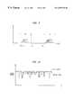
- FIG. 3illustrates the effects of conventional diversity reception as plotted in terms of depth of fade with respect to fading probability.
- ten percent of the time the signal fadeis 25dB or more.
- ten percent of the time the signal fadeis 15dB of more.
- ten percent of the time the signal fadeis 10dB or more.
- a diversity gain of 10dBis therefore realized for two-branch reception in contrast to one-branch reception using the same transmitted signal strength.
- the fade marginis less for two-branch reception in this case and link budget can therefore be conserved since a given reception criteria can be realized using lower signal strength and multiple reception branches.
- reception diversity at a mobile stationis impractical since typical hand-held or portable mobile units cannot include multiple antennas that are spatially separated.
- the present inventionimproves downlink performance in a mobile communication system without increasing base station transmit power by employing base station transmitter diversity combined with mobile station reception equalization.
- a multichannel transmitter including multiple transmit antennastransmits a signal and one or more additional independent versions of the same signal with time delay to a mobile station.
- the energy of the independent received versions of the signalare equalized in the frequency domain at the mobile station using an equalizer or synchronized in time in a RAKE receiver to produce a composite signal.
- the diversity gain effectmay thus be achieved so that the fading immunity margin of the system is increased, less total transmitted power is required and generated interference is reduced.
- FIG. 1illustrates a conventional mobile communication system including a base station having a single transmit antenna
- FIG. 2illustrates multipaths of a signal received at the mobile station of FIG. 1 in the time domain
- FIG. 3illustrates the effects of receiver diversity for multiple branch reception
- FIG. 4illustrates a mobile communication system of an embodiment of the invention
- FIG. 5illustrates transmit diversity of an embodiment of the invention at a base station including plural transmit antennas
- FIG. 6illustrates a base station transmitter of an embodiment of the invention
- FIG. 7illustrates a mobile station receiver of an embodiment of the invention
- FIG. 8illustrates an embodiment of an equalizer of the mobile station receiver of FIG. 7
- FIG. 9is a graph illustrating the received multipaths of a first independent version of the signal transmitted without delay and received multipaths of a second independent version of the signal transmitted a predetermined delay time after transmission of the first version, as operated on in the equalizer portions of FIG. 8;
- FIG. 10illustrates independent fading of the independent versions of the signal
- FIG. 11illustrates a RAKE architecture of an alternative embodiment of the mobile station receiver of FIG. 7 .
- FIG. 4illustrates a mobile communication system of a preferred embodiment of the invention which utilizes transmit diversity and reception equalization.
- the mobile communication systemmay be a TDMA, GSM or CDMA mobile communication system.
- the mobile communication systemincludes a plurality of base stations 30 and 31 which wirelessly transmit and receive communication signals to/from mobile station 10 .
- each of base stations 30 and 31may cover respective sectors.
- Mobile switching center 40is connected to the plurality of base stations 30 and 31 via communication lines L and is further coupled to public switched telephone network (PSTN) 50 to enable communication between mobile station 10 and another party on PSTN 50 .
- PSTNpublic switched telephone network
- base station 30includes two antennas 301 and 302 that are spatially separated horizontally by at least 7-10 ⁇ , wherein ⁇ is wavelength.
- the antennasare spatially separated so that the independent versions of the same signal may be transmitted to mobile station 10 over different effective radio channels that are not subject to identical fading.
- each of antennas 301 and 302may be spatially separated vertically.
- each of antennas 301 and 302may be orthogonally polarized (vertical/horizontal dual polarization or dual slant polarization) with respect to each other to provide different independently fading transmissions.
- transmission independencemay be provided through a combination of spatial separation and orthogonal polarization of antennas 301 and 302 .
- the base stationmay transmit the independent versions of the same signal over any number of antennas to further improve the diversity effect.
- FIG. 5illustrates a first independent version of the signal and the corresponding multipaths as transmitted from antenna 301 to mobile station 10 indicated by solid lines.
- FIG. 5also illustrates a second independent version of the signal and the corresponding multipaths as transmitted from antenna 302 to mobile station 10 indicated by dashed lines, the second independent version being transmitted from antenna 302 a predetermined delay time ⁇ after transmission of the signal from antenna 301 .
- the signalis transmitted from antenna 302 an artificial delay time after transmission of the signal from antenna 301 .
- FIG. 6illustrates the base station transmitter of base station 30 of FIG. 5 in greater detail.
- Input data or voice Inis provided to coder 310 .
- coder 310may perform pulse code modulation (PCM) for example.
- PCMpulse code modulation
- coder 310may be a variable-rate vocoder (video compression or data compression) using conventional coding algorithms as would be well within the level of ordinary skill.
- the coded signalis provided to interleaver 312 which interleaves the coded signal to mitigate the loss of entire blocks of data due to fading.
- the interleaved datais provided to modulator 314 which modulates the interleaved data using DQPSK ( ⁇ /4 differential quadrature phase shift keying) for TDMA systems, GMSK (gaussian minimum shift keying) for GSM systems and QPSK (quadrature phase shift keying) for CDMA systems, for example.
- DQPSK⁇ /4 differential quadrature phase shift keying
- GMSKGaussian minimum shift keying
- QPSKquadrature phase shift keying
- the modulated signal output from modulator 314is provided to amplifier 330 which amplifies the modulated signal and provides the amplified signal to antenna 301 for wireless transmission to mobile station 10 .
- the modulated signalis also provided from modulator 314 to fixed delay element 320 which delays the modulated signal by a predetermined delay time ⁇ and then subsequently outputs the delayed signal.
- the predetermined delay time ⁇is selected to be greater than one information bit period of the transmitted signal to prevent RF lobing where nulls are formed in the transmit pattern as in the case of simultaneous transmission from an array of antennas fed from a common source, and inter-symbol interference where the transition edges between digital states suffer time dispersion.
- Amplifier 331amplifies the delayed signal output from delay element 320 and provides the amplified signal to antenna 302 for wireless transmission to mobile station 10 .
- the signalis transmitted from antenna 302 to mobile station 10 independently of and at a predetermined delay time ⁇ after transmission of the signal from antenna 301 .
- the modulated signalis also provided to delay element 32 N which delays the modulated signal by a predetermined delay time N ⁇ and then subsequently outputs the delayed signal.
- Amplifier 33 Namplifies the delayed signal provided from delay element 32 N and then provides the amplified signal to antenna 30 N for wireless transmission to mobile station 10 .
- the signalis transmitted from antenna 30 N to mobile station 10 independently of and at a predetermined delay time N ⁇ after transmission of the signal from antenna 301 .
- Nis an integer and that the number of transmission branches in the base station is not limited. The diversity effect improves as the number of transmission branches increases.
- FIG. 7illustrates a preferred embodiment of a receiver of mobile station 10 of FIG. 4 .
- Antenna 101wirelessly receives the signals transmitted from antennas 301 , 302 and 30 N of the base station transmitter of FIG. 6.
- a signal as receivedis provided to demodulator 102 which demodulates the signal in accordance with the corresponding modulation scheme used at base station 30 . For instance, DQPSK, GMSK and QPSK demodulation is carried out by demodulator 102 for TDMA, GSM and CDMA systems, respectively.
- the demodulated signalis provided to equalizer 104 , which will be described in greater detail hereinafter, such that the independent versions of the signal as transmitted by antennas 301 , 302 and 30 N with delay may be combined to form a composite signal.
- the composite signal output from equalizer 104is provided to de-interleaver 106 and is de-interleaved in a complimentary manner to the interleaving performed by interleaver 312 of the base station transmitter of FIG. 6 .
- the de-interleaved signalis provided to decoder 108 which performs corresponding decoding to provide signal Out, which may be data or voice.
- FIG. 8illustrates an equalizer of a preferred embodiment of the invention for use in TDMA systems.
- Equalizer 104is a split equalizer including equalizer portions 120 and 130 which are each three-tap adaptive equalizers. Fixed delay element 140 is included as coupled along the delay lines between equalizer portions 120 and 130 . It is to be understood that FIG. 8 illustrates an example of an equalizer for a mobile station that receives two independent versions of a signal since two equalizer portions are implemented.
- equalizer 104includes the same number of equalizer portions N as antennas N over which independent versions of the signal are transmitted from the base station.
- a respective fixed delay element 140is coupled between each pair of equalizer portions.
- the demodulated signal output from demodulator 102 of FIG. 7is provided to fixed or variable delay element 121 and multiplier 123 of equalizer portion 120 of FIG. 8 .
- Delay element 121delays the demodulated signal by delay time ⁇ 1 and provides a delayed output to delay element 122 and multiplier 124 .
- Delay element 122further delays the output of delay element 121 by delay time ⁇ 2 and provides a delayed output to multiplier 125 .
- Delay elements 121 and 122form a tapped delay line and each provide delay of 1 ⁇ 4, 1 ⁇ 2 or one full information bit period of the transmitted signal, but generally provide a much shorter delay than a full information bit period.
- the delayed output of delay element 122is also provided to fixed long delay element 140 as a delayed output of equalizer portion 120 .
- Each of multipliers 123 , 124 and 125respectively multiply the corresponding inputs by magnitude weightings h 1 , h 2 and h 3 .
- the magnitude weightings h 1 , h 2 and h 3are provided adaptively to equalize the signal in a conventional manner.
- the multiplied outputs of each of multipliers 123 - 125are provided to summer 126 which sums the multiplied outputs to provide a summed output of equalizer portion 120 that is output to equalizer portion 130 .
- the bit periodis very long relative to the environmentally induced natural multipath echoes.
- a two-tap equalizeris the longest equalizer used in practice since the use of more taps produces no benefits.
- the delay between tapsis as small as possible, usually 1 ⁇ 4 of a bit period.
- Other equalizersmay use 1 ⁇ 2 or one full bit delays between successive taps. Because of the long bit period in TDMA systems which corresponds inversely with the very narrow bandwidth of 30KHz, the 1 ⁇ 4 bit period spaced second tap is relatively ineffective for compensating channel distortions and consequently less than 1 dB of gain is achieved.
- the TDMA equalizeris often turned off and differential detection is used instead without compensation for intersymbol interference.
- the environmentally induced multipath echoescreate severe intersymbol interference that must be compensated by an equalizer.
- 5 to 8 tap equalizersare typically employed and effective gain is much greater than 10 dB of link budget improvement.
- the distortion produced due to multipathis analyzed in the frequency domain and the weights for the successive taps are set to create a flat response over the channel bandwidth.
- element 140delays the delayed output of equalizer portion 120 , as provided from delay element 122 , by the predetermined delay time ⁇ described with reference to FIG. 6 .
- Fixed long delay element 140provides a delay of at least one information bit period, preferably two or three information bit periods of the transmitted signal, so that the independent versions of the received signal may be separated.
- the output of fixed long delay element 140is provided to delay element 131 and multiplier 133 of equalizer portion 130 .
- Delay element 131delays the output of fixed delay element 140 by delay time ⁇ 3 and provides a delayed output to delay element 132 and multiplier 134 .
- Delay element 132delays the output of delay element 131 by delay time ⁇ 4 and provides a delayed output to multiplier 135 .
- Delay elements 131 and 132form a tapped delay line and provide delay as described previously with regard to delay elements 121 and 122 .
- Multipliers 133 , 134 and 135respectively multiply the corresponding inputs by magnitude weightings h 4 , h 5 and h 6 to provide corresponding multiplied outputs.
- the magnitude weightings h 4 , h 5 and h 6are provided adaptively to equalize the signal in a conventional manner.
- the multiplied outputs of each of the multipliers 133 - 135are provided to summer 136 which sums the multiplied outputs to provide a summed output that is output to summer 137 .
- Summer 137sums the summed output of equalizer portion 120 provided from summer 126 and the summed output of summer 136 to provide an equalizer output signal corresponding to the composite signal described with respect to FIG. 7 as output to de-interleaver 106 .
- fixed long delay element 140separates the taps of the tapped delay line of equalizer portion 120 from the taps of the tapped delay line of equalizer portion 130 by the fixed delay.
- the independent versions of the signal transmitted from base station 30 and received by mobile station 10must be separable. Transmission of the independent versions of the signal with artificial delay from the base station transmitter as illustrated in FIG. 6 enables the independent versions to be separated upon reception.
- Use of a predetermined time delay ⁇ greater than one information bit period of the transmitted signalprevents RF lobing where nulls are formed in the transmit pattern as in the case of simultaneous transmission from an array of antennas fed from a common source, and inter-symbol interference where the transition edges between digital states suffer time dispersion.
- the predetermined delay time ⁇is one information bit period of the transmitted signal. More preferably, the predetermined delay time ⁇ is at least two or three information bit periods of the transmitted signal.
- a signal transmitted from antenna 301 to mobile station 10for example includes multipaths that are delayed due to the signal reflecting off environmental obstacles.
- the multipaths of a transmitted signal which occur due to environmental obstaclesare illustrated in FIG. 2 .
- the signal transmitted from antenna 301 of the base station transmitteris received first at mobile station 10 and is then provided to equalizer 104 .
- the signal including the multipathsare provided to equalizer portion 120 of equalizer 104 illustrated in FIG. 8, which attempts to mitigate smearing of the multipaths to provide an equalized signal as an output of summer 126 .
- the signal including the multipathsis provided from delay element 122 to fixed delay element 140 which delays the signal by the predetermined delay time ⁇ and subsequently provides the signal including the multipaths to equalizer portion 130 for equalization.
- equalizer portion 130attempts to mitigate smearing of the multipaths of the independent version of the signal transmitted from antenna 301 of the base station transmitter and equalizer portion 120 simultaneously attempts to mitigate smearing of the multipaths of the independent version of the signal transmitted from antenna 302 of the base station transmitter.
- the equalized independent versions of the signal as output from summers 126 and 136are summed in summer 137 to provide the composite signal.
- FIG. 9illustrates the independent versions of the signal including multipaths as operated on by equalizer portion 120 and 130 of FIG. 8 at a corresponding point in time.
- the independent version of the signal that is first transmitted from antenna 301 of the base station transmitter and including multipathsis indicated by solid lines.
- this independent version of the signal including multipathsis operated on by equalizer portion 130 as indicated.
- the independent version of the signal that is transmitted from antenna 302 of the base station transmitter and including multipathsis indicated by dashed lines.
- this respective independent version of the signal including multipathsis operated on by equalizer portion 120 .
- the independent versions of the signal as illustratedare separated by predetermined delay time ⁇ when transmitted and are thus operated on simultaneously by equalizer portions 120 and 130 which are separated from each other by fixed delay element 140 .
- an independent version of the signalis transmitted from antenna 302 predetermined delay time ⁇ after an independent version of the signal is transmitted from antenna 301 .
- the independent versions of the signalmay thus be separated as described above by equalizer 104 and may be combined to provide a composite signal.
- the independent versions of the signalare transmitted from different antennas 301 and 302 that are either spatially separated and/or orthogonally polarized with respect to each other.
- the independent versions of the signalare thus transmitted over different paths and therefore are not subjected to correlated fading.
- the independent versions of the signalmay thus be combined to provide a composite signal having effective signal strength greater than either of the independent versions of the signal due to the effects of diversity gain.
- the independent version of the signal transmitted first from antenna 301is subjected to different fading than the independent version of the signal transmitted a predetermined delay time ⁇ thereafter by antenna 302 .
- the independent versions of the signalare combined to provide a composite signal in equalizer 104 , the net effect is more than simply adding the signal strength of the independent versions of the signal so that the composite signal has merely twice the signal strength of either of the independent versions of the signal taken alone. This mere doubling of the signal strength would correspond to a 3 dB increase.
- the effective signal strength of the composite signalmay actually be 6-15 or more dB stronger than that of either independent versions of the signal.
- equalizer 104which is illustrated in greater detail in FIG. 8 .
- the equalizer of FIG. 8is described as a TDMA equalizer but may be used as a GSM equalizer by changing the number of taps, as described previously.
- equalizer 104 of FIG. 7is replaced with specialized RAKE architecture 200 illustrated in FIG. 11 .
- RAKE architectures for CDMA systemsexperience multipath induced channel distortions.
- the bandwidth of CDMA systemsis very wide, corresponding to a very short bit period, and the environmental induced echoes are very far apart in terms of numbers of bits.
- the intersymbol interferencespans many bits in the CDMA systems, rather than just two adjacent bits for TDMA systems or eight adjacent bits for GSM systems as described previously.
- the system architecturetherefore uses variable time delays between a small number of RAKE fingers to avoid complex equalizer design with hundreds or thousands of taps, most of which would be set to magnitude zero. Accordingly, in a RAKE based CDMA system, only the top three or four effective echoes are tracked, synchronized and summed to form a compensated signal.
- the scanning function for choosing the variable delaysis done in the time domain to identify the delay offsets where the echoes reside.
- demodulated I and Q componentsare input to data bus 210 of RAKE architecture 200 .
- the I and Q signal componentsare provided from data bus 210 to searching unit 212 which searches out the echoes of the received signal based on the I and Q signal components.
- Searching unit 212provides an indication of where the echoes are in the received signal to finger control unit 214 which provides control signals to RAKE fingers 216 , 218 and 220 .
- RAKE fingers 216 , 218 and 220are each coupled to the I and Q signal components provided along data bus 210 and each delay a respective echo of the received signal by a specific delay in accordance with the control signals provided from finger control unit 214 .
- RAKE fingers 216 , 218 and 220are thus adaptive to delay the respective multipath echoes of a received signal as illustrated in FIG. 2 so that the outputs of RAKE fingers 216 , 218 and 220 as provided to summer 230 include respective echoes of the received signal that are synchronized with each other in time to effectively mitigate smear.
- the I and Q componentsare also provided from data bus 210 to fixed delay element 240 which delays the I and Q components by the predetermined delay time ⁇ .
- the delayed I and Q signal componentsare provided from fixed delay element 240 to data bus 260 .
- the I and Q signal componentsare provided from data bus 260 to searching unit 262 .
- Searching unit 262 , finger control unit 264 and RAKE fingers 266 , 268 and 270function similarly as searching unit 212 , finger control unit 214 and rake fingers 216 , 218 and 220 respectively.
- Finger control unit 214provides a control signal to searching unit 262 and finger control unit 264 to coordinate searching and finger control based on the indication of where the echoes of the signal are located as determined by searching unit 212 .
- RAKE fingers 266 , 268 and 270are thus adaptive to provide outputs to summer 230 which include respective echoes of the received signal that are synchronized with each other in time to mitigate smear.
- Summer 230 of RAKE architecture 200provides a summed output to a de-interleaver which provides a de-interleaved output to a decoder.
- the decodermay be a Viterbi soft decoder for example.
- a signal transmitted from antenna 301 of base station 30 of FIG. 5is demodulated by the corresponding demodulator which provides I and Q signal components of the signal to data bus 210 of RAKE architecture 200 .
- the signal including the multipathsare processed by the set of RAKE fingers 216 , 218 and 220 to mitigate smearing.
- the I and Q components of the received signalare then delayed by fixed delay element 240 and then provided to data bus 260 to be processed by the set of RAKE fingers 266 , 268 and 270 .
- the independent version of the signal transmitted from antenna 302 of FIG. 5(as demodulated by the corresponding demodulator) is provided as I and Q signal components to data bus 210 .
- the I and Q components of the delayed independent version of the signal including the multipaths transmitted from antenna 302are processed by the set of RAKE fingers 216 , 218 and 220 simultaneously as the set of RAKE fingers 266 , 268 and 270 process the I and Q signal components of the signal transmitted from antenna 301 .
- the outputs of the RAKE fingersare provided to summer 230 which outputs a composite signal having effective signal strength greater than either of the independent versions of the signal due to the effects of diversity gain.
- RAKE architecture 200 of FIG. 11illustrates an example for a mobile station that receives two independent versions of a signal as transmitted from a base station since two sets of RAKE fingers are implemented.
- RAKE architecture 200includes the same number of RAKE finger sets as antennas over which independent versions of the signal are transmitted from the base station.
- a respective fixed delay element 240is coupled between each pair of RAKE finger sets.
- searching units, finger control units and RAKE fingersare typical RAKE architecture elements.
- the equalizer of FIG. 8can be simplified for certain types of environments. For a TDMA environment that uses a narrow effective band with a 30 KHz for instance, there is little delay spread in the environment because the bit period is very long. For such a specific case, the equalizer of FIG. 8 can be reduced to a single two-tap equalizer wherein equalizer portion 120 includes only multiplier 123 as a first fixed tap and equalizer portion 130 includes only multiplier 133 as a second fixed tap.
- the simplified equalizerwould not include delay elements 121 , 122 , 131 and 132 and multipliers 124 , 125 , 134 and 135 . Only fixed delay element 140 would be implemented between equalizer portions 120 and 130 , thus simplifying the equalizer such that weight, size and cost may be reduced.
Landscapes
- Engineering & Computer Science (AREA)
- Computer Networks & Wireless Communication (AREA)
- Signal Processing (AREA)
- Radio Transmission System (AREA)
- Mobile Radio Communication Systems (AREA)
- Cable Transmission Systems, Equalization Of Radio And Reduction Of Echo (AREA)
Abstract
Description
Claims (15)
Priority Applications (9)
| Application Number | Priority Date | Filing Date | Title |
|---|---|---|---|
| US09/188,563US6259730B1 (en) | 1998-11-10 | 1998-11-10 | Transmit diversity and reception equalization for radio links |
| CA002283197ACA2283197A1 (en) | 1998-11-10 | 1999-09-23 | Transmit diversity and reception equalization for radio links |
| TW088116399ATW443055B (en) | 1998-11-10 | 1999-09-23 | Transmit diversity and reception equalization for radio links |
| EP99308698.2AEP1003297B8 (en) | 1998-11-10 | 1999-11-02 | Transmit diversity and reception equalization for radio links |
| BR9905140-0ABR9905140A (en) | 1998-11-10 | 1999-11-03 | Diversity of transmission and equalization for radio connections. |
| KR1019990049060AKR100719637B1 (en) | 1998-11-10 | 1999-11-06 | Transmit diversity and reception equalization for radio links |
| CN99123680ACN1253430A (en) | 1998-11-10 | 1999-11-08 | Emission diversity used in radio link and receiving equality |
| JP31878999AJP3803218B2 (en) | 1998-11-10 | 1999-11-09 | Mobile communication base station and mobile station |
| US09/839,127US6771689B2 (en) | 1998-11-10 | 2001-04-23 | Transmit diversity and reception equalization for radio links |
Applications Claiming Priority (1)
| Application Number | Priority Date | Filing Date | Title |
|---|---|---|---|
| US09/188,563US6259730B1 (en) | 1998-11-10 | 1998-11-10 | Transmit diversity and reception equalization for radio links |
Related Child Applications (1)
| Application Number | Title | Priority Date | Filing Date |
|---|---|---|---|
| US09/839,127DivisionUS6771689B2 (en) | 1998-11-10 | 2001-04-23 | Transmit diversity and reception equalization for radio links |
Publications (1)
| Publication Number | Publication Date |
|---|---|
| US6259730B1true US6259730B1 (en) | 2001-07-10 |
Family
ID=22693677
Family Applications (2)
| Application Number | Title | Priority Date | Filing Date |
|---|---|---|---|
| US09/188,563Expired - LifetimeUS6259730B1 (en) | 1998-11-10 | 1998-11-10 | Transmit diversity and reception equalization for radio links |
| US09/839,127Expired - LifetimeUS6771689B2 (en) | 1998-11-10 | 2001-04-23 | Transmit diversity and reception equalization for radio links |
Family Applications After (1)
| Application Number | Title | Priority Date | Filing Date |
|---|---|---|---|
| US09/839,127Expired - LifetimeUS6771689B2 (en) | 1998-11-10 | 2001-04-23 | Transmit diversity and reception equalization for radio links |
Country Status (8)
| Country | Link |
|---|---|
| US (2) | US6259730B1 (en) |
| EP (1) | EP1003297B8 (en) |
| JP (1) | JP3803218B2 (en) |
| KR (1) | KR100719637B1 (en) |
| CN (1) | CN1253430A (en) |
| BR (1) | BR9905140A (en) |
| CA (1) | CA2283197A1 (en) |
| TW (1) | TW443055B (en) |
Cited By (31)
| Publication number | Priority date | Publication date | Assignee | Title |
|---|---|---|---|---|
| US20020018529A1 (en)* | 2000-07-05 | 2002-02-14 | Texas Instruments Incorporated | Code division multiple access wireless system with time reversed spaced time block transmitter diversity encoding |
| US6377812B1 (en)* | 1997-11-20 | 2002-04-23 | University Of Maryland | Combined power control and space-time diversity in mobile cellular communications |
| US20030063557A1 (en)* | 2001-07-13 | 2003-04-03 | Mitsubishi Denki Kabushiki Kaisha | Multi-user detection in an MC-CDMA telecommunication system |
| US6601213B1 (en)* | 1999-06-15 | 2003-07-29 | Mitsubishi Denki Kabushiki Kaisha | Demodulator and communications system |
| US20030185322A1 (en)* | 2002-03-27 | 2003-10-02 | Tsutomu Takahashi | Digital radio receiver |
| US20060215786A1 (en)* | 2005-03-24 | 2006-09-28 | Harris Corporation | System and method for communicating data using constant amplitude equalized waveform |
| US20070253470A1 (en)* | 2006-04-28 | 2007-11-01 | Bachl Rainer W | Multi-path equalizer configuration technique |
| US20080013494A1 (en)* | 1998-08-31 | 2008-01-17 | Qualcomm Incorporated | Signal splitting method for limiting peak power in a cdma system |
| US20080064428A1 (en)* | 1999-02-16 | 2008-03-13 | Mitsubishi Denki Kabushiki Kaisha | Radio Communication System, a Transmitter and a Receiver |
| US20080240279A1 (en)* | 2004-02-10 | 2008-10-02 | T-Mobile Deutschland Gmbh | Method and Device For Operating Mimo Air Interfaces in Mobile Communications Systems |
| US20090304024A1 (en)* | 2008-06-09 | 2009-12-10 | Qualcomm Incorporated | Increasing capacity in wireless communications |
| US20100022193A1 (en)* | 2005-10-27 | 2010-01-28 | Bruno Melis | Method and System for Multiple Antenna Communications Using Multiple Transmission Modes, Related Apparatus and Computer Program Product |
| US20100029262A1 (en)* | 2008-08-01 | 2010-02-04 | Qualcomm Incorporated | Cell detection with interference cancellation |
| US20100046595A1 (en)* | 2008-08-19 | 2010-02-25 | Qualcomm Incorporated | Semi-coherent timing propagation for geran multislot configurations |
| US20100046660A1 (en)* | 2008-05-13 | 2010-02-25 | Qualcomm Incorporated | Interference cancellation under non-stationary conditions |
| US20100130150A1 (en)* | 2006-11-29 | 2010-05-27 | D Amico Valeria | Switched beam antenna with digitally controlled weighted radio frequency combining |
| US20110026418A1 (en)* | 2007-12-19 | 2011-02-03 | Loris Bollea | Method and system for switched beam antenna communications |
| US20110051864A1 (en)* | 2009-09-03 | 2011-03-03 | Qualcomm Incorporated | Multi-stage interference suppression |
| US20110312275A1 (en)* | 2010-06-22 | 2011-12-22 | Qualcomm Incorporated | Signal reception method and apparatus for non-stationary channels |
| CN103067058A (en)* | 2012-12-25 | 2013-04-24 | 熊猫电子集团有限公司 | Short wave receiving and sending integration digital signal processing module based on delayed diversity |
| US8744360B2 (en) | 2005-01-05 | 2014-06-03 | Atc Technologies, Inc. | Adaptive beam forming with multi-user detection and interference reduction in satellite communication systems and methods |
| US8787509B2 (en) | 2009-06-04 | 2014-07-22 | Qualcomm Incorporated | Iterative interference cancellation receiver |
| US8831149B2 (en) | 2009-09-03 | 2014-09-09 | Qualcomm Incorporated | Symbol estimation methods and apparatuses |
| US9055545B2 (en) | 2005-08-22 | 2015-06-09 | Qualcomm Incorporated | Interference cancellation for wireless communications |
| US9071344B2 (en) | 2005-08-22 | 2015-06-30 | Qualcomm Incorporated | Reverse link interference cancellation |
| US9160577B2 (en) | 2009-04-30 | 2015-10-13 | Qualcomm Incorporated | Hybrid SAIC receiver |
| US9237515B2 (en) | 2008-08-01 | 2016-01-12 | Qualcomm Incorporated | Successive detection and cancellation for cell pilot detection |
| US9509452B2 (en) | 2009-11-27 | 2016-11-29 | Qualcomm Incorporated | Increasing capacity in wireless communications |
| US9673837B2 (en) | 2009-11-27 | 2017-06-06 | Qualcomm Incorporated | Increasing capacity in wireless communications |
| US20200186219A1 (en)* | 2012-12-17 | 2020-06-11 | Ethertronics, Inc. | Communication load balancing using distributed antenna beam steering techniques |
| US10869193B2 (en)* | 2019-04-15 | 2020-12-15 | GM Global Technology Operations LLC | Method and system for establishing secured wireless communications using electromagnetic polarization techniques |
Families Citing this family (38)
| Publication number | Priority date | Publication date | Assignee | Title |
|---|---|---|---|---|
| US7076228B1 (en)* | 1999-11-10 | 2006-07-11 | Rilling Kenneth F | Interference reduction for multiple signals |
| US7139324B1 (en)* | 2000-06-02 | 2006-11-21 | Nokia Networks Oy | Closed loop feedback system for improved down link performance |
| DE60008930T2 (en)* | 2000-12-04 | 2005-01-27 | Mitsubishi Denki K.K. | SYNTHESIS RECEIVING METHOD AND SYNTHESIS RECEIVER |
| GB2371947B (en) | 2001-02-01 | 2005-02-23 | Fujitsu Ltd | Communications systems |
| WO2003023999A1 (en)* | 2001-08-31 | 2003-03-20 | Linkair Communications, Inc. | A method of error-correcting encoding source data elements and corresponding iterative decoder |
| JP4634672B2 (en)* | 2001-09-25 | 2011-02-16 | 三菱電機株式会社 | Site diversity transmitter / receiver |
| WO2003041322A2 (en)* | 2001-10-31 | 2003-05-15 | Infineon Technologies Ag | Hardware structure and method for a transceiver device with configurable co-processors for mobile radio applications |
| KR100485516B1 (en)* | 2002-04-22 | 2005-04-27 | 주식회사 케이티프리텔 | Basestation and method for receiving and processing signal in the basestation |
| US7136627B2 (en) | 2002-08-05 | 2006-11-14 | Nokia Corporation | Transmission diversity with two cross-polarised antennas arrays |
| US7505741B2 (en)* | 2002-11-01 | 2009-03-17 | Magnolia Broadband Inc. | Processing diversity signals using a delay |
| ATE367024T1 (en)* | 2003-04-04 | 2007-08-15 | Mitsubishi Electric Corp | PRE-EQUALIZATION OF A MULTI- CARRIER CDMA SYSTEM VIA TIME-VARIANT TRANSMISSION CHANNELS |
| US7580672B2 (en)* | 2003-06-27 | 2009-08-25 | Qualcomm Incorporated | Synthetic path diversity repeater |
| US20050042988A1 (en)* | 2003-08-18 | 2005-02-24 | Alcatel | Combined open and closed loop transmission diversity system |
| US7437135B2 (en) | 2003-10-30 | 2008-10-14 | Interdigital Technology Corporation | Joint channel equalizer interference canceller advanced receiver |
| US7400692B2 (en) | 2004-01-14 | 2008-07-15 | Interdigital Technology Corporation | Telescoping window based equalization |
| KR100993183B1 (en) | 2004-03-09 | 2010-11-10 | 톰슨 라이센싱 | Hybrid Rake / Equalizer Receivers for Spread Spectrum Systems |
| EP1726111B1 (en) | 2004-03-15 | 2019-05-29 | Apple Inc. | Pilot design for ofdm systems with four transmit antennas |
| EP1730864B1 (en)* | 2004-04-02 | 2018-10-31 | Apple Inc. | Wireless comunication methods, systems, and signal structures |
| GB0410321D0 (en)* | 2004-05-08 | 2004-06-09 | Univ Surrey | Data transmission |
| EP1766806B1 (en) | 2004-06-22 | 2017-11-01 | Apple Inc. | Closed loop mimo systems and methods |
| US8014377B2 (en) | 2004-06-24 | 2011-09-06 | Nortel Networks Limited | Efficient location updates, paging and short bursts |
| EP2993851B1 (en) | 2004-06-24 | 2019-04-24 | Apple Inc. | Preambles in ofdma system |
| US7263335B2 (en)* | 2004-07-19 | 2007-08-28 | Purewave Networks, Inc. | Multi-connection, non-simultaneous frequency diversity in radio communication systems |
| CN1842988B (en)* | 2004-09-17 | 2011-11-23 | 松下电器产业株式会社 | Wireless transmission system and wireless transmission method, and wireless station and transmitting station used therein |
| WO2006039812A1 (en) | 2004-10-15 | 2006-04-20 | Nortel Networks Limited | Communication resource allocation systems and methods |
| US8194526B2 (en)* | 2005-10-24 | 2012-06-05 | General Motors Llc | Method for data communication via a voice channel of a wireless communication network |
| US8194779B2 (en)* | 2005-10-24 | 2012-06-05 | General Motors Llc | Method for data communication via a voice channel of a wireless communication network |
| US8259840B2 (en)* | 2005-10-24 | 2012-09-04 | General Motors Llc | Data communication via a voice channel of a wireless communication network using discontinuities |
| EP1788722A1 (en) | 2005-11-21 | 2007-05-23 | Nortel Networks Limited | Transmission method and related base station |
| US8913677B2 (en)* | 2007-08-20 | 2014-12-16 | The Regents Of The University Of California | Symbol timing relative offset multi antenna system and method |
| GB2460112A (en)* | 2008-05-19 | 2009-11-25 | Nokia Corp | Controlling transmission diversity by delaying a signal on a second transmit path relative to a first transmit path |
| JP4621757B2 (en)* | 2008-07-04 | 2011-01-26 | 京セラ株式会社 | Wireless communication system, wireless transmission device, wireless reception device, and wireless communication method |
| WO2010030399A1 (en) | 2008-09-12 | 2010-03-18 | Qualcomm Incorporated | A method and apparatus for signaling to a mobile device which set of training sequence codes to use for a communication link |
| US10136426B2 (en)* | 2014-12-05 | 2018-11-20 | Dominant Technologies, LLC | Wireless conferencing system using narrow-band channels |
| US10568155B2 (en) | 2012-04-13 | 2020-02-18 | Dominant Technologies, LLC | Communication and data handling in a mesh network using duplex radios |
| US9031117B2 (en)* | 2012-12-06 | 2015-05-12 | Qualcomm Incorporated | Methods and apparatus for handling fingers with large delay spread through utility optimization |
| KR102391724B1 (en)* | 2015-12-18 | 2022-04-28 | 삼성전자주식회사 | Apparatus and method for non orthogonal multiple access in a wireless communication system |
| EP3481142B1 (en)* | 2016-08-08 | 2020-10-28 | Huawei Technologies Co., Ltd. | Data transmission method and transmitting terminal device |
Citations (5)
| Publication number | Priority date | Publication date | Assignee | Title |
|---|---|---|---|---|
| US5283780A (en)* | 1990-10-18 | 1994-02-01 | Stanford Telecommunications, Inc. | Digital audio broadcasting system |
| US5692018A (en)* | 1995-04-11 | 1997-11-25 | Nec Corporation | Time-diversity interference canceler with add/subtract/select circuit responsive to decision error |
| US5757853A (en)* | 1995-03-22 | 1998-05-26 | Nec Corporation | Spread spectrum time diversity communications system |
| US5859870A (en)* | 1995-10-23 | 1999-01-12 | Nec Corporation | Time diversity transmission-reception system |
| US5982825A (en)* | 1995-12-28 | 1999-11-09 | Nec Corporation | Method and apparatus for cancelling interference jamming in digital radio transmission |
Family Cites Families (12)
| Publication number | Priority date | Publication date | Assignee | Title |
|---|---|---|---|---|
| JPS58197929A (en)* | 1982-05-14 | 1983-11-17 | Nec Corp | Diversity communication system |
| GB2127992B (en)* | 1982-09-28 | 1986-04-16 | Audim Sa | Cross-correlator |
| US5513176A (en) | 1990-12-07 | 1996-04-30 | Qualcomm Incorporated | Dual distributed antenna system |
| JP2603608B2 (en)* | 1992-05-20 | 1997-04-23 | 日本無線株式会社 | Propagation time difference correction circuit for switched space diversity digital wireless communication. |
| JPH0771084A (en)* | 1993-06-14 | 1995-03-14 | Takaya Takase | Shock absorption for impulsive sound of floor in woody system-steel frame system housing construction |
| US5517523A (en)* | 1993-06-16 | 1996-05-14 | Motorola, Inc. | Bridge-tap equalizer method and apparatus |
| CA2146445C (en)* | 1993-08-06 | 1999-06-01 | Fumiyuki Adachi | Receiver and repeater for spread-spectrum communications |
| US5494680A (en) | 1993-12-08 | 1996-02-27 | Minnesota Mining And Manufacturing Company | Transdermal delivery device |
| CN1078988C (en)* | 1995-06-13 | 2002-02-06 | Ntt移动通信网株式会社 | CDMA demodulator |
| US5926470A (en) | 1996-05-22 | 1999-07-20 | Qualcomm Incorporated | Method and apparatus for providing diversity in hard handoff for a CDMA system |
| JP2751920B2 (en)* | 1996-06-21 | 1998-05-18 | 日本電気株式会社 | Method and apparatus for synchronously acquiring spread spectrum signal |
| JPH11266180A (en)* | 1998-03-18 | 1999-09-28 | Fujitsu Ltd | Array antenna system for wireless base station |
- 1998
- 1998-11-10USUS09/188,563patent/US6259730B1/ennot_activeExpired - Lifetime
- 1999
- 1999-09-23TWTW088116399Apatent/TW443055B/ennot_activeIP Right Cessation
- 1999-09-23CACA002283197Apatent/CA2283197A1/ennot_activeAbandoned
- 1999-11-02EPEP99308698.2Apatent/EP1003297B8/ennot_activeExpired - Lifetime
- 1999-11-03BRBR9905140-0Apatent/BR9905140A/ennot_activeApplication Discontinuation
- 1999-11-06KRKR1019990049060Apatent/KR100719637B1/ennot_activeExpired - Fee Related
- 1999-11-08CNCN99123680Apatent/CN1253430A/enactivePending
- 1999-11-09JPJP31878999Apatent/JP3803218B2/ennot_activeExpired - Fee Related
- 2001
- 2001-04-23USUS09/839,127patent/US6771689B2/ennot_activeExpired - Lifetime
Patent Citations (5)
| Publication number | Priority date | Publication date | Assignee | Title |
|---|---|---|---|---|
| US5283780A (en)* | 1990-10-18 | 1994-02-01 | Stanford Telecommunications, Inc. | Digital audio broadcasting system |
| US5757853A (en)* | 1995-03-22 | 1998-05-26 | Nec Corporation | Spread spectrum time diversity communications system |
| US5692018A (en)* | 1995-04-11 | 1997-11-25 | Nec Corporation | Time-diversity interference canceler with add/subtract/select circuit responsive to decision error |
| US5859870A (en)* | 1995-10-23 | 1999-01-12 | Nec Corporation | Time diversity transmission-reception system |
| US5982825A (en)* | 1995-12-28 | 1999-11-09 | Nec Corporation | Method and apparatus for cancelling interference jamming in digital radio transmission |
Cited By (56)
| Publication number | Priority date | Publication date | Assignee | Title |
|---|---|---|---|---|
| US6377812B1 (en)* | 1997-11-20 | 2002-04-23 | University Of Maryland | Combined power control and space-time diversity in mobile cellular communications |
| US7965688B2 (en)* | 1998-08-31 | 2011-06-21 | Qualcomm Incorporated | Signal splitting method for limiting peak power in a CDMA system |
| US20080013494A1 (en)* | 1998-08-31 | 2008-01-17 | Qualcomm Incorporated | Signal splitting method for limiting peak power in a cdma system |
| US8027649B2 (en) | 1999-02-16 | 2011-09-27 | Mitsubishi Denki Kabushiki Kaisha | Radio communication system, a transmitter and a receiver |
| US7929922B2 (en) | 1999-02-16 | 2011-04-19 | Mitsubishi Denki Kabushiki Kaisha | Radio communication system, a transmitter and a receiver |
| US7346316B1 (en)* | 1999-02-16 | 2008-03-18 | Mitsubishi Denki Kabushiki Kaisha | Radio communication system, a transmitter and a receiver |
| US20080064335A1 (en)* | 1999-02-16 | 2008-03-13 | Mitsubishi Denki Kabushiki Kaisha | Radio Communication System, a Transmitter and a Receiver |
| US20080064428A1 (en)* | 1999-02-16 | 2008-03-13 | Mitsubishi Denki Kabushiki Kaisha | Radio Communication System, a Transmitter and a Receiver |
| US6601213B1 (en)* | 1999-06-15 | 2003-07-29 | Mitsubishi Denki Kabushiki Kaisha | Demodulator and communications system |
| US7154958B2 (en)* | 2000-07-05 | 2006-12-26 | Texas Instruments Incorporated | Code division multiple access wireless system with time reversed space time block transmitter diversity |
| US20020018529A1 (en)* | 2000-07-05 | 2002-02-14 | Texas Instruments Incorporated | Code division multiple access wireless system with time reversed spaced time block transmitter diversity encoding |
| US7327668B2 (en)* | 2001-07-13 | 2008-02-05 | Mitsubishi Denki Kabushiki Kaisha | Multi-user detection in an MC-CDMA telecommunication system |
| US20030063557A1 (en)* | 2001-07-13 | 2003-04-03 | Mitsubishi Denki Kabushiki Kaisha | Multi-user detection in an MC-CDMA telecommunication system |
| US7139343B2 (en)* | 2002-03-27 | 2006-11-21 | Hitachi Kokusai Electric Inc. | Digital radio receiver |
| US20030185322A1 (en)* | 2002-03-27 | 2003-10-02 | Tsutomu Takahashi | Digital radio receiver |
| US8059742B2 (en) | 2004-02-10 | 2011-11-15 | T-Mobile Deutschland Gmbh | Method and device for operating MIMO air interfaces in mobile communications systems |
| US20080240279A1 (en)* | 2004-02-10 | 2008-10-02 | T-Mobile Deutschland Gmbh | Method and Device For Operating Mimo Air Interfaces in Mobile Communications Systems |
| US8744360B2 (en) | 2005-01-05 | 2014-06-03 | Atc Technologies, Inc. | Adaptive beam forming with multi-user detection and interference reduction in satellite communication systems and methods |
| US20060215786A1 (en)* | 2005-03-24 | 2006-09-28 | Harris Corporation | System and method for communicating data using constant amplitude equalized waveform |
| US7508884B2 (en)* | 2005-03-24 | 2009-03-24 | Harris Corporation | System and method for communicating data using constant amplitude equalized waveform |
| US9071344B2 (en) | 2005-08-22 | 2015-06-30 | Qualcomm Incorporated | Reverse link interference cancellation |
| US9055545B2 (en) | 2005-08-22 | 2015-06-09 | Qualcomm Incorporated | Interference cancellation for wireless communications |
| US8437712B2 (en)* | 2005-10-27 | 2013-05-07 | Telecom Italia S.P.A. | Method and system for multiple antenna communications using multiple transmission modes, related apparatus and computer program product |
| US20100022193A1 (en)* | 2005-10-27 | 2010-01-28 | Bruno Melis | Method and System for Multiple Antenna Communications Using Multiple Transmission Modes, Related Apparatus and Computer Program Product |
| US20070253470A1 (en)* | 2006-04-28 | 2007-11-01 | Bachl Rainer W | Multi-path equalizer configuration technique |
| US7643539B2 (en)* | 2006-04-28 | 2010-01-05 | Alcatel-Lucent Usa Inc. | Multi-path equalizer configuration technique |
| US20100130150A1 (en)* | 2006-11-29 | 2010-05-27 | D Amico Valeria | Switched beam antenna with digitally controlled weighted radio frequency combining |
| US8509724B2 (en) | 2006-11-29 | 2013-08-13 | Telecom Italia S.P.A. | Switched beam antenna with digitally controlled weighted radio frequency combining |
| US9001803B2 (en) | 2007-12-19 | 2015-04-07 | Telecom Italia S.P.A. | Method and system for switched beam antenna communications |
| US20110026418A1 (en)* | 2007-12-19 | 2011-02-03 | Loris Bollea | Method and system for switched beam antenna communications |
| US8675796B2 (en) | 2008-05-13 | 2014-03-18 | Qualcomm Incorporated | Interference cancellation under non-stationary conditions |
| US20100046660A1 (en)* | 2008-05-13 | 2010-02-25 | Qualcomm Incorporated | Interference cancellation under non-stationary conditions |
| US8995417B2 (en) | 2008-06-09 | 2015-03-31 | Qualcomm Incorporated | Increasing capacity in wireless communication |
| US9408165B2 (en) | 2008-06-09 | 2016-08-02 | Qualcomm Incorporated | Increasing capacity in wireless communications |
| US20090304024A1 (en)* | 2008-06-09 | 2009-12-10 | Qualcomm Incorporated | Increasing capacity in wireless communications |
| US9014152B2 (en) | 2008-06-09 | 2015-04-21 | Qualcomm Incorporated | Increasing capacity in wireless communications |
| US9277487B2 (en) | 2008-08-01 | 2016-03-01 | Qualcomm Incorporated | Cell detection with interference cancellation |
| US9237515B2 (en) | 2008-08-01 | 2016-01-12 | Qualcomm Incorporated | Successive detection and cancellation for cell pilot detection |
| US20100029262A1 (en)* | 2008-08-01 | 2010-02-04 | Qualcomm Incorporated | Cell detection with interference cancellation |
| US20100046595A1 (en)* | 2008-08-19 | 2010-02-25 | Qualcomm Incorporated | Semi-coherent timing propagation for geran multislot configurations |
| US8509293B2 (en) | 2008-08-19 | 2013-08-13 | Qualcomm Incorporated | Semi-coherent timing propagation for GERAN multislot configurations |
| US9160577B2 (en) | 2009-04-30 | 2015-10-13 | Qualcomm Incorporated | Hybrid SAIC receiver |
| US8787509B2 (en) | 2009-06-04 | 2014-07-22 | Qualcomm Incorporated | Iterative interference cancellation receiver |
| US20110051864A1 (en)* | 2009-09-03 | 2011-03-03 | Qualcomm Incorporated | Multi-stage interference suppression |
| US8619928B2 (en) | 2009-09-03 | 2013-12-31 | Qualcomm Incorporated | Multi-stage interference suppression |
| US8831149B2 (en) | 2009-09-03 | 2014-09-09 | Qualcomm Incorporated | Symbol estimation methods and apparatuses |
| US9509452B2 (en) | 2009-11-27 | 2016-11-29 | Qualcomm Incorporated | Increasing capacity in wireless communications |
| US10790861B2 (en) | 2009-11-27 | 2020-09-29 | Qualcomm Incorporated | Increasing capacity in wireless communications |
| US9673837B2 (en) | 2009-11-27 | 2017-06-06 | Qualcomm Incorporated | Increasing capacity in wireless communications |
| US20110312275A1 (en)* | 2010-06-22 | 2011-12-22 | Qualcomm Incorporated | Signal reception method and apparatus for non-stationary channels |
| US8396440B2 (en)* | 2010-06-22 | 2013-03-12 | Qualcomm Incorporated | Signal reception method and apparatus for non-stationary channels |
| US20200186219A1 (en)* | 2012-12-17 | 2020-06-11 | Ethertronics, Inc. | Communication load balancing using distributed antenna beam steering techniques |
| US11700042B2 (en)* | 2012-12-17 | 2023-07-11 | KYOCERA AVX Components (San Diego), Inc. | Communication load balancing using distributed antenna beam steering techniques |
| CN103067058B (en)* | 2012-12-25 | 2015-09-09 | 熊猫电子集团有限公司 | Based on the shortwave transmitting-receiving integrated Digital Signal processing module of delay diversity |
| CN103067058A (en)* | 2012-12-25 | 2013-04-24 | 熊猫电子集团有限公司 | Short wave receiving and sending integration digital signal processing module based on delayed diversity |
| US10869193B2 (en)* | 2019-04-15 | 2020-12-15 | GM Global Technology Operations LLC | Method and system for establishing secured wireless communications using electromagnetic polarization techniques |
Also Published As
| Publication number | Publication date |
|---|---|
| EP1003297B1 (en) | 2013-06-19 |
| EP1003297A3 (en) | 2005-09-21 |
| EP1003297B8 (en) | 2015-02-25 |
| BR9905140A (en) | 2000-10-10 |
| US6771689B2 (en) | 2004-08-03 |
| CA2283197A1 (en) | 2000-05-10 |
| JP3803218B2 (en) | 2006-08-02 |
| CN1253430A (en) | 2000-05-17 |
| TW443055B (en) | 2001-06-23 |
| EP1003297A2 (en) | 2000-05-24 |
| US20010019592A1 (en) | 2001-09-06 |
| KR20000035271A (en) | 2000-06-26 |
| JP2000151485A (en) | 2000-05-30 |
| KR100719637B1 (en) | 2007-05-17 |
Similar Documents
| Publication | Publication Date | Title |
|---|---|---|
| US6259730B1 (en) | Transmit diversity and reception equalization for radio links | |
| EP1172944B1 (en) | Wireless transmitter and receiver | |
| EP1073212B1 (en) | Wireless system with transmitter with multiple antennas and combining open loop and closed loop transmit diversity | |
| JP2734953B2 (en) | CDMA receiver | |
| US5901185A (en) | Systems and methods for data-augmented, pilot-symbol-assisted radiotelephone communications | |
| US7444170B2 (en) | Co-channel wireless communication methods and systems using nonsymmetrical alphabets | |
| US20060234662A1 (en) | Low complexity equalizer for radio receiver | |
| EP1376896A1 (en) | Iterative channel estimation for receiving wireless transmissions using multiple antennas | |
| CA2076290A1 (en) | Radio receiver and transmitter providing diversity | |
| US20030008623A1 (en) | Receiving Apparatus and Transmitting Apparatus | |
| US7319822B2 (en) | System and method of space-time equalization to mitigate effects of fading and scintillation for wireless communication | |
| EP0728384A1 (en) | Diversity receiver with combiner for equalization and diversity transmitter with splitter and delay | |
| WO2005002067A2 (en) | Multi-carrier spread spectrum using non-linear modification of sub-carrier bands | |
| MXPA99010091A (en) | Diversity of transmission and equalization of reception for link by ra | |
| KR20060116887A (en) | Communication diversity method for mobile stations | |
| CA2405875C (en) | Transmitter diversity technique for wireless communications | |
| Liu et al. | Space-Frequency OFDM System with Null-Steering Beamformer | |
| Winters | Smart antennas for the EDGE wireless TDMA system | |
| US20080260013A1 (en) | Equalization with Selection of Samples | |
| KR20020017007A (en) | Interference noise removing appratus in wireless microphone |
Legal Events
| Date | Code | Title | Description |
|---|---|---|---|
| AS | Assignment | Owner name:LUCENT TECHNOLOGIES INC., NEW JERSEY Free format text:ASSIGNMENT OF ASSIGNORS INTEREST;ASSIGNOR:SOLONDZ, MAX AARON;REEL/FRAME:009589/0130 Effective date:19981110 | |
| STCF | Information on status: patent grant | Free format text:PATENTED CASE | |
| FPAY | Fee payment | Year of fee payment:4 | |
| FEPP | Fee payment procedure | Free format text:PAYOR NUMBER ASSIGNED (ORIGINAL EVENT CODE: ASPN); ENTITY STATUS OF PATENT OWNER: LARGE ENTITY | |
| FPAY | Fee payment | Year of fee payment:8 | |
| FPAY | Fee payment | Year of fee payment:12 | |
| AS | Assignment | Owner name:CREDIT SUISSE AG, NEW YORK Free format text:SECURITY INTEREST;ASSIGNOR:ALCATEL-LUCENT USA INC.;REEL/FRAME:030510/0627 Effective date:20130130 | |
| AS | Assignment | Owner name:ALCATEL-LUCENT USA INC., NEW JERSEY Free format text:RELEASE BY SECURED PARTY;ASSIGNOR:CREDIT SUISSE AG;REEL/FRAME:033950/0261 Effective date:20140819 | |
| AS | Assignment | Owner name:OMEGA CREDIT OPPORTUNITIES MASTER FUND, LP, NEW YORK Free format text:SECURITY INTEREST;ASSIGNOR:WSOU INVESTMENTS, LLC;REEL/FRAME:043966/0574 Effective date:20170822 Owner name:OMEGA CREDIT OPPORTUNITIES MASTER FUND, LP, NEW YO Free format text:SECURITY INTEREST;ASSIGNOR:WSOU INVESTMENTS, LLC;REEL/FRAME:043966/0574 Effective date:20170822 | |
| AS | Assignment | Owner name:WSOU INVESTMENTS, LLC, CALIFORNIA Free format text:ASSIGNMENT OF ASSIGNORS INTEREST;ASSIGNOR:ALCATEL LUCENT;REEL/FRAME:044000/0053 Effective date:20170722 | |
| AS | Assignment | Owner name:WSOU INVESTMENTS, LLC, CALIFORNIA Free format text:RELEASE BY SECURED PARTY;ASSIGNOR:OCO OPPORTUNITIES MASTER FUND, L.P. (F/K/A OMEGA CREDIT OPPORTUNITIES MASTER FUND LP;REEL/FRAME:049246/0405 Effective date:20190516 | |
| AS | Assignment | Owner name:OT WSOU TERRIER HOLDINGS, LLC, CALIFORNIA Free format text:SECURITY INTEREST;ASSIGNOR:WSOU INVESTMENTS, LLC;REEL/FRAME:056990/0081 Effective date:20210528 |