US6259170B1 - Bi-color led trailer connector circuit protector and indicator - Google Patents
Bi-color led trailer connector circuit protector and indicatorDownload PDFInfo
- Publication number
- US6259170B1 US6259170B1US09/330,627US33062799AUS6259170B1US 6259170 B1US6259170 B1US 6259170B1US 33062799 AUS33062799 AUS 33062799AUS 6259170 B1US6259170 B1US 6259170B1
- Authority
- US
- United States
- Prior art keywords
- trailer
- electrical
- circuit
- connectors
- electrical system
- Prior art date
- Legal status (The legal status is an assumption and is not a legal conclusion. Google has not performed a legal analysis and makes no representation as to the accuracy of the status listed.)
- Expired - Fee Related
Links
- 230000001012protectorEffects0.000title1
- 230000005611electricityEffects0.000claimsabstractdescription6
- 239000004033plasticSubstances0.000claimsdescription12
- 229920003023plasticPolymers0.000claimsdescription12
- 230000000295complement effectEffects0.000claimsdescription9
- 239000000463materialSubstances0.000claimsdescription4
- 238000001228spectrumMethods0.000claimsdescription3
- NIXOWILDQLNWCW-UHFFFAOYSA-Nacrylic acid groupChemical groupC(C=C)(=O)ONIXOWILDQLNWCW-UHFFFAOYSA-N0.000description5
- 238000005286illuminationMethods0.000description4
- 238000001429visible spectrumMethods0.000description4
- 229920001940conductive polymerPolymers0.000description2
- 238000005516engineering processMethods0.000description2
- 239000004593EpoxySubstances0.000description1
- 229920005479Lucite®Polymers0.000description1
- 239000004020conductorSubstances0.000description1
- 238000010276constructionMethods0.000description1
- 238000010586diagramMethods0.000description1
- 239000003822epoxy resinSubstances0.000description1
- 238000009434installationMethods0.000description1
- 229920000647polyepoxidePolymers0.000description1
Images


Classifications
- B—PERFORMING OPERATIONS; TRANSPORTING
- B60—VEHICLES IN GENERAL
- B60Q—ARRANGEMENT OF SIGNALLING OR LIGHTING DEVICES, THE MOUNTING OR SUPPORTING THEREOF OR CIRCUITS THEREFOR, FOR VEHICLES IN GENERAL
- B60Q1/00—Arrangement of optical signalling or lighting devices, the mounting or supporting thereof or circuits therefor
- B60Q1/26—Arrangement of optical signalling or lighting devices, the mounting or supporting thereof or circuits therefor the devices being primarily intended to indicate the vehicle, or parts thereof, or to give signals, to other traffic
- B60Q1/30—Arrangement of optical signalling or lighting devices, the mounting or supporting thereof or circuits therefor the devices being primarily intended to indicate the vehicle, or parts thereof, or to give signals, to other traffic for indicating rear of vehicle, e.g. by means of reflecting surfaces
- B60Q1/305—Indicating devices for towed vehicles
Definitions
- This inventionrelates generally to an electrical connector and, more particularly, to an electrical plug for connecting a tow vehicle electrical system wires to a trailer electrical system wires.
- Trailers configured to be towed behind automotive vehiclestypically include trailer electrical systems that include lights, wiring and a trailer electrical plug.
- the lightsare generally mounted on or near a rear portion of the trailers they are mounted on.
- the lightsinclude left and right turn signal lights, and left and right taillights.
- Each lightnormally includes an incandescent lamp and a socket configured to receive the incandescent lamp.
- the wiresextend from the light sockets to the trailer electrical plug.
- a standard type of plug used in such electrical systemsis known as a “four-flat” trailer wiring plug and is configured to plug into a complementary vehicle electrical plug mounted on a tow vehicle. When joined together, the trailer and vehicle plugs connect tow vehicle electrical system wires to the trailer electrical system wires, which transmits power from vehicle lighting circuits to the trailer electrical system to illuminate the trailer lights.
- Each trailer electrical plugtypically includes four electrical connectors. One of these four connectors is connected to a chassis ground wire that connects to a chassis ground lead from each light through the trailer chassis. Another of the four connectors is connected to a wire that extends and connects to the left turn signal light. A third of the four connectors is connected to a wire that extends and connects to the right turn signal light. The remaining connector is connected to a wire that extends to both the left and right taillights.
- the four connectors of the trailer pluggenerally include one female and three male connectors encased in a parallel disposition in a plastic jacket or casing.
- the vehicle plugincludes four connectors encased in a plastic jacket.
- the four connectors of the vehicle pluggenerally include one male and three female connectors to complement the one female and three male connectors of the trailer plug.
- the one female trailer plug connector and the one male vehicle plug connectorare conventionally the chassis ground connection.
- the other three connectorsare conventionally, in order from the ground connectors, the tail light connectors and the left and right turn signal light connectors. This convention insures that the correct contacts are made between taillight and turn signal light circuits whenever a trailer electrical system is connected to a tow vehicle electrical system.
- Trailer electrical systemsare also known to include circuit breakers.
- the circuit breakersare configured to open circuits that are shorted or supplied with an excessive amount of electrical current. The circuit breakers must then be reset before the circuit can be closed after a fault has been corrected.
- Some trailer electrical systemsalso include sensor lights that illuminate when a given circuit is closed and extinguish when the circuit is opened.
- PTC devicespolymeric positive temperature coefficient resettable fuses
- LED'sbi-color light-emitting diodes
- Each monochromatic light sourceincludes a tiny chip that generates a very narrow band of electromagnetic energy in the visible spectrum, i.e., colored light.
- the two chipsare encased in a single epoxy lens, which may also be colored.
- an electrical trailer plug devicein accordance with this invention includes at least one electrical connector configured to connect an electrical current path of a vehicle electrical system to an electrical current path of a trailer electrical system to complete an electrical circuit supplying electricity from the vehicle electrical system to a lamp supported on the trailer.
- a circuit protection devicein the form of a circuit breaker or fuse is connected in the circuit between at least one of the connectors and a lamp connected in the circuit.
- the circuit protection deviceis configured to limit current flow in the circuit when the current exceeds a predetermined value.
- the deviceincludes a first sensor light and is configured to illuminate the first sensor light when current is flowing in the circuit but has not exceeded the predetermined value.
- the devicemay also include a second sensor light and be configured to illuminate the second sensor light when the circuit protection device is limiting current flow in the circuit in response to a fault in the circuit.
- a plug devicethat includes three sets of connectors, circuit protection devices and lights along with a third connector serving to provide a common ground connection.
- the four connectorscomplete three electrical circuits that supply electricity from the vehicle electrical system to four trailer lamps supported on the trailer.
- LEDbi-color light-emitting diode
- PTCpolymeric positive temperature coefficient
- the three bi-color LED'sare encapsulated into a one-piece translucent cast acrylic block that is inserted as a single piece into the device. This provides simplified assembly over the installation of six separate “loose piece” LED's. This one-piece construction also promotes a superior moisture seal when the components are overmolded into a plug casing. The moisture seal is superior because only one component (the block) protrudes from the surface of the plug casing.
- trailer plugthat includes components that help identify trailer electrical problems such as shorts in the wiring or excessive loads, that can identify a problem in the towing vehicle electrical system, that protect the towing vehicle wiring against shorts or overloads in a trailer electrical system and that is constructed in such a way as to be resistant to moisture damage.
- FIG. 2is a schematic diagram of electrical components of a trailer plug device constructed according to the invention and connecting a tow vehicle electrical system to a trailer electrical system;
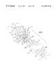
- FIG. 1is a perspective view of a trailer plug device constructed according to the invention shown disconnected from a tow vehicle plug, the trailer plug device including the electrical components diagrammed in FIG. 2;
- FIG. 3is a perspective view of a trailer plug device constructed according to a second embodiment of the invention and shown unplugged from and between a tow vehicle plug and a conventional trailer plug.
- FIG. 1A first embodiment of an electrical trailer plug device 10 for connecting a trailer electrical system to a tow vehicle electrical system is generally shown at 10 in FIG. 1.
- FIG. 3A second embodiment is generally indicated at 10 ′ in FIG. 3 .
- Reference numerals with the designation prime (′) in FIG. 3indicate alternative configurations of elements that also appear in the first embodiment. Unless indicated otherwise, where a portion of the following description uses a reference numeral to refer to the figures, I intend that portion of the description to apply equally to elements designated by primed numerals in FIG. 3 .
- Tow vehicle and trailer electrical systemsare schematically represented at 11 and 13 , respectively in FIG. 2 .
- the trailer plug device 10comprises four electrical connectors, shown at 12 , 14 , 16 and 18 in FIGS. 1 and 2.
- the connectors 12 , 14 , 16 , 18are configured to connect four electrical wires 20 , 22 , 24 , 26 of the trailer electrical system 13 to four corresponding electrical wires of the tow vehicle electrical system 11 (shown at 28 , 30 , 32 , 34 in FIG. 3 with regard to the second embodiment).
- a ground connector 18 of the four connectors 12 , 14 , 16 , 18connects respective ground wires 34 , 26 of the vehicle and trailer electrical systems 11 , 13 that serve as a common ground 35 .
- a tow vehicle plugsuch as the plug generally indicated at 36 in FIG.
- the three remaining connectors 12 , 14 , 16complete three electrical circuits through the common ground to supply electricity from the vehicle electrical system to four trailer lamps 38 , 40 , 42 supported on the trailer.
- a first of these three circuitsprovides power to a right turn signal mounted on the trailer and represented by node 38 in FIG. 2.
- a second of the three circuitsprovides power to a left turn signal mounted on the trailer and represented by node 40 in FIG. 2 .
- the third circuitpowers left and right taillights that are mounted on the trailer and are represented by node 42 in FIG. 2 .
- Circuit protection devices 44 , 46 , 48 in the form of a circuit breaker or fuseis connected in each of the three circuits between the connectors 12 , 14 , 16 , 18 and the lamps 38 , 40 , 42 connected in the respective circuits as shown in FIG. 2 .
- the circuit protection devices 44 , 46 , 48are each configured to limit current flow in their respective circuits when current flow exceeds a predetermined value.
- Each circuitincludes two sensor lights 50 , 52 ; 54 , 56 ; 58 , 60 and a combination of circuit elements that cause the first sensor light 50 , 54 , 58 in each circuit to illuminate when current in that circuit is flowing but has not exceeded the predetermined value.
- each circuitalso causes the second sensor light 52 , 56 , 60 in each circuit to illuminate when the circuit protection device 44 , 46 , 48 in the circuit is limiting current flow in response to a fault in the circuit.
- both sensor lights 50 , 52 ; 54 , 56 ; 58 , 60are extinguished when the circuit is unpowered. All the above components are encased in a trailer plug body or housing generally indicated at 62 in FIG. 1 .
- Each sensor light 50 , 52 ; 54 , 56 ; 58 , 60includes a monochromatic light source that is configured to emit a visible band of electromagnetic energy.
- the visible light band that the monochromatic light source of the first sensor light 50 , 54 , 58 in each circuit emitsis in the green portion of the visible spectrum.
- the visible light band that the monochromatic light source of the second sensor light 52 , 56 , 60 in each circuit emitsis in the red portion of the visible spectrum.
- the two sensor lights 50 , 52 ; 54 , 56 ; 58 , 60 in each circuitare included in a single common-anode bi-color light-emitting diode (LED) shown at 64 , 66 and 68 in FIG. 1 .
- Each monochromatic light sourceincludes a tiny chip that generates a very narrow band of electromagnetic energy in the visible spectrum, i.e., colored light.
- the two chips in each bi-color LED 64 , 66 , 68are encased in a translucent lens made of an epoxy resin. The translucent lens may also be colored.
- Bi-color LED's of this typeare available from Luminex under the trade name Luminex-Lites® in a variety of chip and lens color combinations.
- the three bi-color LED's 64 , 66 , 68 of each plug device 10are encased in a block 70 of translucent material such as Lucite® cast acrylic.
- the block 70 of clear material containing the LED's 64 , 66 , 68 , the connectors 12 , 14 , 16 , 18 and the circuit protection device 44 , 46 , 48are encased in a plastic casing 74 of the trailer plug body 62 .
- One surface 72 of block 70 of clear material containing the LED's 64 , 66 , 68is left exposed through an outer wall of the plastic casing 74 so that the illumination of the LED's 64 , 66 , 68 can be observed.
- the circuit protection devices 44 , 46 , 48 included in the circuitsare configured to automatically reset by closing their respective circuits once a fault that caused a high current condition has been cleared and electrical power is removed from the affected circuit.
- Each circuit protection device 44 , 46 , 48is a polymeric positive temperature coefficient resettable fuse (PTC device) that uses conductive-polymer technology to limits the flow of dangerously high current during fault conditions in the circuit.
- PTC devicesare solid-state devices configured to reset after a fault is cleared and power to the circuit is removed.
- PTC devicesare available from Raychem Corporation under the trade name PolySwitch®.
- the combination of circuit elements that controls illumination of the first and second sensor lights in each circuitalso limits current through the sensor lights 50 , 52 ; 54 , 56 ; 58 , 60 to a level that prevents the lights from burning out.
- the combination of circuit elements in each circuitincludes respective circuit protection devices 44 , 46 , 48 ; respective transistors 78 , 80 , 82 and respective first resistors 84 , 86 , 88 ; second resistors 90 , 92 , 94 ; and third resistors 96 , 98 , 100 .
- the second sensor light 52 , 56 , 60 in each respective circuitincludes two leads, one lead being connected into the circuit in series with the respective first resistor 84 , 90 , 96 at a respective common anode 102 , 104 , 106 disposed between the respective circuit protection device 44 , 46 , 48 and the trailer electrical system 13 .
- the other lead of the second sensor light 52 , 56 , 60is connected into the circuit at a point between the respective connector 12 , 14 , 16 and the respective circuit protection device 44 , 46 , 48 .
- the respective first sensor light 50 , 54 , 58 in each circuitalso includes two leads, one lead being connected in the circuit at the respective common anode 102 , 104 , 106 (between the respective connector 12 , 14 , 16 and the respective circuit protection device 44 , 46 , 48 ) and the other lead being connected to an input of the respective transistor 78 , 80 , 82 .
- An output of the respective transistor 78 , 80 , 82is connected to ground through the respective third resistor 88 , 94 , 100 .
- the base of the respective transistor 78 , 80 , 82is connected into the circuit through the respective second resistor (base resistor) 86 , 92 , 98 , connecting into the circuit between the respective circuit protection device 44 , 46 , 48 and the trailer electrical system 13 .
- the respective first and third resistors 84 , 90 , 96 ; 88 , 94 , 100 in each circuitare included to limit current flow through the respective first and second sensor light portions 50 , 54 , 58 ; 52 , 56 , 60 of the LED 64 , 66 , 68 in that circuit.
- the transistor 78 , 80 , 82 in each of the three circuitsis configured to turn on through the base resistor 86 , 92 , 98 when the circuit protection device 44 , 46 , 48 in that circuit is closed (normal condition) and current is flowing in the circuit.
- the PTC in that circuitwill open, stopping current flow to the trailer portion of the circuits 13 and to the base of the transistor 78 , 80 , 82 in that circuit which causes the transistor 78 , 80 , 82 to shut down.
- the transistor 78 , 80 , 82shuts down the green light source 50 , 54 , 58 of the LED 64 , 66 , 68 in that circuit will turn off and current will flow, instead, along a secondary path 114 , 116 , 118 through the red light source 52 , 56 , 60 of the LED 64 , 66 , 68 and the first resistor 84 , 90 , 96 , grounding through the overloaded trailer portion 13 of the circuit and causing the red light source 52 , 56 , 60 of the LED 64 , 66 , 68 to illuminate.
- the three circuitsdiffer in that the PTCs in the first and second circuits (the turn signal circuits) are configured for 4 amps while the PTC in the third circuit (the tail light circuit) is configured for 5 amps.
- the trailer plug device 10has a first end 120 configured to removably connect, both mechanically and electrically, to a complementary end of the vehicle plug 36 , and a second end 122 configured to connect, both mechanically and electrically, to the electrical wires 20 , 22 , 24 , 26 of the trailer electrical system 13 .
- the trailer plug device 10includes four electrical connectors 12 , 14 , 16 , 18 , the first connector 12 of which is connected to a current path or wire 20 that extends and connects to the right turn signal light.
- a second connector 14 of the four connectorsis connected to a current path or wire 22 that extends and connects to the left turn signal light.
- a third connector 16 of the four connectorsis connected to a current path or wire 24 that extends and connects to both the left and right taillights.
- the fourth connector 18is configured to connect to a trailer chassis ground wire 26 that connects through the trailer chassis to chassis ground leads 124 , 126 , 128 from each light 38 , 40 , 42 .
- the first, second and third of the four connectors 12 , 14 , 16 , 18 of the trailer plug device 10are generally cylindrical female connectors and the fourth connector 18 is a contoured probe-shaped male connector.
- the trailer plug connectors 12 , 14 , 16 , 18are configured to complement a tow vehicle plug 36 that includes one female connector 130 and three male connectors 132 , 134 , 136 .
- the three male connectors 132 , 134 , 136 of the tow vehicle plug 36are shaped to be received by an interference fit into the female connectors 12 , 14 , 16 of the trailer plug device 62 .
- the male connector of the trailer plug device 62is shaped to be received by an interference fit into the female connector 130 of the tow vehicle plug 36 .
- the four trailer plug connectors 12 , 14 , 16 , 18are encased in a parallel coplanar disposition in the plastic casing 74 .
- the portion of the casing 74 defining the first end 120 of the trailer plug device 10is shaped to complement the shape of one end of the tow vehicle plug 36 through which the tow vehicle plug connectors 130 , 132 , 134 , 136 are exposed.
- the trailer and vehicle plugs 10 , 36connect tow vehicle electrical system wires 28 , 30 , 32 , 34 to the trailer electrical system 13 to transmit power from vehicle lighting circuits to the trailer electrical system 13 to illuminate the trailer lights 38 , 40 , 42 .
- the shape of the trailer plug device 10 and the shape of the vehicle plug 36are conventional shapes in the industry also known as a “four-flat” configuration.
- the “four-flat” trailer wiring plugis configured to plug into any complementary-shaped vehicle electrical plug such as the tow vehicle plug shown at 36 in FIG. 1 .
- the single male trailer plug connector 18 of the trailer plug device 10 and the one female vehicle plug connector 130 of the tow vehicle plug 36are the common chassis ground connection.
- the other three pairs of connectorsare, in order from the ground connectors, the tail light connectors 16 , 132 , the left turn signal light connectors 14 , 134 and the right turn signal light connectors 12 , 136 .
- This conventioninsures that the correct contacts are made between tail light and turn signal light circuits whenever a trailer electrical system 13 configured according to the convention is connected to a tow vehicle electrical system 1 that is also configured according to the convention.
- the second end 122 ′ of the trailer plug device 10 ′is disposed opposite the first end 120 ′ of the trailer plug device 10 ′ and is configured to removably connect, both mechanically and electrically, to a complementary conventional trailer plug, generally indicated at 140 in FIG. 3 .
- the conventional trailer plug 140is connected to the trailer electrical system 13 by four trailer plug wires 20 ′, 22 ′, 24 ′, 26 ′.
- the portion of the casing 74 ′ defining the second end 122 ′ of the trailer plug device 10 ′is shaped to complement the shape of one end 142 of the conventional trailer plug 140 through which connectors 144 , 146 , 148 , 150 of the conventional trailer plug 140 are exposed.
- the shape of the conventional trailer plug 140conforms to the conventional “four-flat” configuration.
- the second end 122 ′ of the inventive trailer plug device 10 ′includes three male connectors 152 , 154 , 156 that plug into three female connectors 142 , 144 , 146 of the conventional trailer plug 140 to make tail light and turn signal light circuit connections, respectively.
- the second end 122 ′ of the inventive trailer plug device 10 ′also includes a single female connector 158 that receives a single male connector 158 of the conventional trailer plug 140 to make the common ground connection for all three circuits.
- the trailer plug device 10may include more or fewer than four connectors to close more or fewer than three circuits. Any number of the circuits may include the circuit components described above including circuit protection devices, sensor lights, transistors and resistors.
- the monochromatic light sources of the first and second sensor lights in each circuitmay be configured to emit visible light bands from other than the green and red portions of the spectrum, so long as the bands emitted by the respective sensor lights are visually differentiable from each other.
- the respective sensor lightsmay be visually differentiable by, for example, emitting respective light beams that are different in color, pattern and/or intensity.
- the various current paths described abovecould be defined by elongated conductors other than wires, e.g., flex cables, circuit board traces etc.
- An electrical trailer plug device 10 constructed according to either the first or the second embodiment of the inventionmay be fabricated by encasing the bi-color LED's 64 , 66 , 68 in the block 70 of clear or translucent cast acrylic.
- the above-described connectors 12 , 14 , 16 , 18 , circuit protection devices 44 , 46 , 48 , bi-color LED's 64 , 66 , 68 , transistors 78 , 80 , 82 and resistorsare then electrically connected together as described above.
- the connectors 12 , 14 , 16 , 18 , circuit protection devices 44 , 46 , 48 , acrylic-encased bi-color LED's 64 , 66 , 68 and the other circuit componentsare then encased in the plastic casing 74 of the trailer plug body 62 .
- the plastic casing 74 of the trailer plug body 62is cast around the components so that one surface 72 of the acrylic block 70 containing the LED's 64 , 66 , 68 and appropriate portions of the electrical connectors 12 , 14 , 16 , 18 are left exposed through an outer wall 160 of the plastic casing 74 .
- the connectors 12 , 14 , 16 , 18are left exposed to allow electrical contact to be made with the connectors 130 , 132 , 134 , 136 of a tow vehicle plug 36 and the acrylic block 70 is left exposed to allow the illumination (or lack of illumination) of the LED's 64 , 66 , 68 to be observed.
- the tail light wire 32 , the two turn-signal wires 28 , 30 and the ground wire 34 from the trailer electrical system 13are also connected to the trailer plug device components before encasing the components within the plastic casing 74 of trailer plug device 10 .
- the ground wire 34is connected to the ground connector 18 .
- the tail light and turn signal wires 28 , 30 , 32are connected to the three circuit protection devices 44 , 46 , 48 that are connected to the respective tail light and turn signal connectors 12 , 14 , 16 ; i.e., the first, second and third electrical connectors 12 , 14 , 16 of the trailer plug device 10 .
- the trailer plug device 10 ′is connected to the tow vehicle electrical system 11 by plugging the second end 122 ′ of the inventive trailer plug device 10 ′ into the conventional trailer plug 140 that is wired to the trailer electrical system 13 .
- Both the first and the second embodiments of the inventionprevent damage to tow vehicle electrical systems from faults in trailer electrical systems while providing a quick and easy way for an operator to confirm proper operation of a trailer electrical system and to trouble-shoot improper operation.
Landscapes
- Engineering & Computer Science (AREA)
- Mechanical Engineering (AREA)
- Details Of Connecting Devices For Male And Female Coupling (AREA)
Abstract
Description
Claims (15)
Priority Applications (1)
| Application Number | Priority Date | Filing Date | Title |
|---|---|---|---|
| US09/330,627US6259170B1 (en) | 1998-06-15 | 1999-06-11 | Bi-color led trailer connector circuit protector and indicator |
Applications Claiming Priority (2)
| Application Number | Priority Date | Filing Date | Title |
|---|---|---|---|
| US8930798P | 1998-06-15 | 1998-06-15 | |
| US09/330,627US6259170B1 (en) | 1998-06-15 | 1999-06-11 | Bi-color led trailer connector circuit protector and indicator |
Publications (1)
| Publication Number | Publication Date |
|---|---|
| US6259170B1true US6259170B1 (en) | 2001-07-10 |
Family
ID=31186071
Family Applications (1)
| Application Number | Title | Priority Date | Filing Date |
|---|---|---|---|
| US09/330,627Expired - Fee RelatedUS6259170B1 (en) | 1998-06-15 | 1999-06-11 | Bi-color led trailer connector circuit protector and indicator |
Country Status (2)
| Country | Link |
|---|---|
| US (1) | US6259170B1 (en) |
| CA (1) | CA2274431C (en) |
Cited By (138)
| Publication number | Priority date | Publication date | Assignee | Title |
|---|---|---|---|---|
| US20020109504A1 (en)* | 1999-09-01 | 2002-08-15 | Champlin Keith S. | Method and apparatus using a circuit model to evaluate cell/battery parameters |
| US20030025481A1 (en)* | 1997-11-03 | 2003-02-06 | Bertness Kevin I. | Energy management system for automotive vehicle |
| US6544078B2 (en)* | 2001-07-18 | 2003-04-08 | Midtronics, Inc. | Battery clamp with integrated current sensor |
| US20040132344A1 (en)* | 2003-01-06 | 2004-07-08 | Plishner Paul J. | Plug and socket holder for replaceably holding diode-based light sources and other radiation sources and receivers |
| US6806716B2 (en) | 1999-04-08 | 2004-10-19 | Kevin I. Bertness | Electronic battery tester |
| US6850037B2 (en) | 1997-11-03 | 2005-02-01 | Midtronics, Inc. | In-vehicle battery monitor |
| US20050037632A1 (en)* | 2003-08-14 | 2005-02-17 | Ihde David H. | Lighted trailer wiring adapter |
| US6885195B2 (en) | 1996-07-29 | 2005-04-26 | Midtronics, Inc. | Method and apparatus for auditing a battery test |
| US6906523B2 (en) | 2000-09-14 | 2005-06-14 | Midtronics, Inc. | Method and apparatus for testing cells and batteries embedded in series/parallel systems |
| US20050130491A1 (en)* | 2003-12-12 | 2005-06-16 | Chirkes Norberto J. | Automobile compact fuse holder |
| US6913483B2 (en) | 2003-06-23 | 2005-07-05 | Midtronics, Inc. | Cable for electronic battery tester |
| US6914413B2 (en) | 1996-07-29 | 2005-07-05 | Midtronics, Inc. | Alternator tester with encoded output |
| US6933727B2 (en) | 2003-03-25 | 2005-08-23 | Midtronics, Inc. | Electronic battery tester cable |
| US6941234B2 (en) | 2001-10-17 | 2005-09-06 | Midtronics, Inc. | Query based electronic battery tester |
| US6967484B2 (en) | 2000-03-27 | 2005-11-22 | Midtronics, Inc. | Electronic battery tester with automotive scan tool communication |
| EP1621401A1 (en)* | 2004-07-27 | 2006-02-01 | Schmitz Gotha Fahrzeugwerke GmbH | Trailer-indicating arrangement for a tractor-trailer-combination |
| US6998847B2 (en) | 2000-03-27 | 2006-02-14 | Midtronics, Inc. | Electronic battery tester with data bus for removable module |
| US7003411B2 (en) | 1997-11-03 | 2006-02-21 | Midtronics, Inc. | Electronic battery tester with network communication |
| US7003410B2 (en) | 1996-07-29 | 2006-02-21 | Midtronics, Inc. | Electronic battery tester with relative test output |
| US7019658B1 (en) | 2003-03-04 | 2006-03-28 | Mobi Technologies, Inc. | Cable traffic indicator |
| US20060085099A1 (en)* | 2004-10-18 | 2006-04-20 | Stmicroelectronics, Inc. | Method and system for driving a vehicle trailer tow connector |
| US20060125482A1 (en)* | 2004-12-09 | 2006-06-15 | Midtronics, Inc. | Apparatus and method for predicting battery capacity and fitness for service from a battery dynamic parameter and a recovery voltage differential |
| USD527708S1 (en) | 2005-02-02 | 2006-09-05 | Hopkins Manufacturing Corporation | Wiring bracket |
| US7106070B2 (en) | 2004-07-22 | 2006-09-12 | Midtronics, Inc. | Broad-band low-inductance cables for making Kelvin connections to electrochemical cells and batteries |
| AU2006100780B4 (en)* | 2004-03-11 | 2006-10-05 | Gravolin, Dennis Ronald Mr | Electrical connector assembly for vehicles |
| US7119686B2 (en) | 2004-04-13 | 2006-10-10 | Midtronics, Inc. | Theft prevention device for automotive vehicle service centers |
| US7118379B1 (en)* | 2004-11-05 | 2006-10-10 | Jen-Ching Wang | Female connector member for towing connector |
| USD530671S1 (en)* | 2004-01-12 | 2006-10-24 | Reedex Inc. | Vehicle-to-trailer coiled electrical-cable |
| US7126341B2 (en) | 1997-11-03 | 2006-10-24 | Midtronics, Inc. | Automotive vehicle electrical system diagnostic device |
| US7154276B2 (en) | 2003-09-05 | 2006-12-26 | Midtronics, Inc. | Method and apparatus for measuring a parameter of a vehicle electrical system |
| US7246015B2 (en) | 1996-07-29 | 2007-07-17 | Midtronics, Inc. | Alternator tester |
| US7247046B1 (en)* | 2006-07-03 | 2007-07-24 | Hon Hai Precision Ind. Co., Ltd | Connector assembly having status indator means |
| WO2007093344A1 (en)* | 2006-02-13 | 2007-08-23 | Ifm Electronic Gmbh | Electrical plug connector |
| US20070208451A1 (en)* | 2006-03-02 | 2007-09-06 | Wolfgang Jacobi | Part of an electrical connecting device |
| US7319304B2 (en) | 2003-07-25 | 2008-01-15 | Midtronics, Inc. | Shunt connection to a PCB of an energy management system employed in an automotive vehicle |
| US20080113522A1 (en)* | 2006-11-14 | 2008-05-15 | Karl Wagner | Surface mount trailer electrical connector |
| US20080142344A1 (en)* | 2006-12-18 | 2008-06-19 | Caterpillar Inc. | Electrical shorting system |
| US7398176B2 (en) | 2000-03-27 | 2008-07-08 | Midtronics, Inc. | Battery testers with secondary functionality |
| US7404724B1 (en)* | 2004-04-02 | 2008-07-29 | Robert Dennis Miller | Connector with ESD inhibiting shell |
| US7408358B2 (en) | 2003-06-16 | 2008-08-05 | Midtronics, Inc. | Electronic battery tester having a user interface to configure a printer |
| US20080204033A1 (en)* | 2007-02-28 | 2008-08-28 | Stmicroelectronics, Inc. | Integrated Circuit and Method for Monitoring and Controlling Power and for Detecting Open Load State |
| US7446536B2 (en) | 2000-03-27 | 2008-11-04 | Midtronics, Inc. | Scan tool for electronic battery tester |
| US7448902B1 (en) | 2008-04-25 | 2008-11-11 | Tyco Electronics Corporation | Mechanical device showing prior mating |
| US7479763B2 (en) | 2001-06-22 | 2009-01-20 | Midtronics, Inc. | Apparatus and method for counteracting self discharge in a storage battery |
| US7498767B2 (en) | 2005-02-16 | 2009-03-03 | Midtronics, Inc. | Centralized data storage of condition of a storage battery at its point of sale |
| US7501795B2 (en) | 2001-06-22 | 2009-03-10 | Midtronics Inc. | Battery charger with booster pack |
| US7505856B2 (en) | 1999-04-08 | 2009-03-17 | Midtronics, Inc. | Battery test module |
| US7557586B1 (en) | 1999-11-01 | 2009-07-07 | Midtronics, Inc. | Electronic battery tester |
| US7595643B2 (en) | 2003-11-11 | 2009-09-29 | Midtronics, Inc. | Apparatus and method for simulating a battery tester with a fixed resistance load |
| US7598743B2 (en) | 2000-03-27 | 2009-10-06 | Midtronics, Inc. | Battery maintenance device having databus connection |
| US7598744B2 (en) | 2000-03-27 | 2009-10-06 | Midtronics, Inc. | Scan tool for electronic battery tester |
| US7598699B2 (en) | 2004-02-20 | 2009-10-06 | Midtronics, Inc. | Replaceable clamp for electronic battery tester |
| US20090269962A1 (en)* | 2008-04-25 | 2009-10-29 | Tyco Electronics Corporation | Medical connector |
| US7619417B2 (en) | 2002-12-31 | 2009-11-17 | Midtronics, Inc. | Battery monitoring system |
| US7642786B2 (en) | 2004-06-01 | 2010-01-05 | Midtronics, Inc. | Battery tester capable of identifying faulty battery post adapters |
| DE202008012786U1 (en) | 2008-09-25 | 2010-03-04 | Erich Jaeger Gmbh & Co. Kg | Connectors |
| US7688074B2 (en) | 1997-11-03 | 2010-03-30 | Midtronics, Inc. | Energy management system for automotive vehicle |
| US7706991B2 (en) | 1996-07-29 | 2010-04-27 | Midtronics, Inc. | Alternator tester |
| US7705602B2 (en) | 1997-11-03 | 2010-04-27 | Midtronics, Inc. | Automotive vehicle electrical system diagnostic device |
| US7710119B2 (en) | 2004-12-09 | 2010-05-04 | Midtronics, Inc. | Battery tester that calculates its own reference values |
| USD615930S1 (en)* | 2008-10-31 | 2010-05-18 | Hopkins Manufacturing Corporation | Trailer wiring connector |
| USD617284S1 (en)* | 2009-05-21 | 2010-06-08 | Cequent Consumer Products | Wiring connector |
| US7772850B2 (en) | 2004-07-12 | 2010-08-10 | Midtronics, Inc. | Wireless battery tester with information encryption means |
| US7774151B2 (en) | 1997-11-03 | 2010-08-10 | Midtronics, Inc. | Wireless battery monitor |
| US7777612B2 (en) | 2004-04-13 | 2010-08-17 | Midtronics, Inc. | Theft prevention device for automotive vehicle service centers |
| US7791348B2 (en) | 2007-02-27 | 2010-09-07 | Midtronics, Inc. | Battery tester with promotion feature to promote use of the battery tester by providing the user with codes having redeemable value |
| US7808375B2 (en) | 2007-04-16 | 2010-10-05 | Midtronics, Inc. | Battery run down indicator |
| EP1791227A3 (en)* | 2005-11-25 | 2010-10-27 | ERICH JAEGER GmbH + Co. KG | Electrical connector |
| US20100301374A1 (en)* | 2009-05-27 | 2010-12-02 | Ssu-Yuan Weng | Led package structure |
| AU2005201078B2 (en)* | 2004-03-11 | 2011-01-20 | Gravolin, Dennis Ronald Mr | Light Emitting Diode Safety Trailer Connector |
| US20110038582A1 (en)* | 2008-09-30 | 2011-02-17 | Apple Inc. | Magnetic connector with optical signal path |
| US7977914B2 (en) | 2003-10-08 | 2011-07-12 | Midtronics, Inc. | Battery maintenance tool with probe light |
| DE202010015647U1 (en)* | 2010-11-23 | 2011-10-05 | Erich Jaeger Gmbh & Co. Kg | Socket for a motor vehicle |
| US8052484B1 (en) | 2010-10-15 | 2011-11-08 | United Technologies Corporation | Electrical connector with offset mating surfaces |
| US8164343B2 (en) | 2003-09-05 | 2012-04-24 | Midtronics, Inc. | Method and apparatus for measuring a parameter of a vehicle electrical system |
| US8198900B2 (en) | 1996-07-29 | 2012-06-12 | Midtronics, Inc. | Automotive battery charging system tester |
| US8203345B2 (en) | 2007-12-06 | 2012-06-19 | Midtronics, Inc. | Storage battery and battery tester |
| US8306690B2 (en) | 2007-07-17 | 2012-11-06 | Midtronics, Inc. | Battery tester for electric vehicle |
| US8344685B2 (en) | 2004-08-20 | 2013-01-01 | Midtronics, Inc. | System for automatically gathering battery information |
| US8436619B2 (en) | 2004-08-20 | 2013-05-07 | Midtronics, Inc. | Integrated tag reader and environment sensor |
| US8442877B2 (en) | 2004-08-20 | 2013-05-14 | Midtronics, Inc. | Simplification of inventory management |
| US8513949B2 (en) | 2000-03-27 | 2013-08-20 | Midtronics, Inc. | Electronic battery tester or charger with databus connection |
| US20130335988A1 (en)* | 2012-06-18 | 2013-12-19 | Cequent Consumer Products, Inc. | Trailer adapter with light |
| US8738309B2 (en) | 2010-09-30 | 2014-05-27 | Midtronics, Inc. | Battery pack maintenance for electric vehicles |
| GB2511095A (en)* | 2013-02-22 | 2014-08-27 | Scorpion Automotive Ltd | Trailer and bulb failure detection |
| US8872517B2 (en) | 1996-07-29 | 2014-10-28 | Midtronics, Inc. | Electronic battery tester with battery age input |
| US8958998B2 (en) | 1997-11-03 | 2015-02-17 | Midtronics, Inc. | Electronic battery tester with network communication |
| US9018958B2 (en) | 2003-09-05 | 2015-04-28 | Midtronics, Inc. | Method and apparatus for measuring a parameter of a vehicle electrical system |
| US20150180179A1 (en)* | 2013-12-19 | 2015-06-25 | Tyco Electronics Amp Korea Ltd | Connector Assembly |
| US9201120B2 (en) | 2010-08-12 | 2015-12-01 | Midtronics, Inc. | Electronic battery tester for testing storage battery |
| US9229062B2 (en) | 2010-05-27 | 2016-01-05 | Midtronics, Inc. | Electronic storage battery diagnostic system |
| US9244100B2 (en) | 2013-03-15 | 2016-01-26 | Midtronics, Inc. | Current clamp with jaw closure detection |
| US9255955B2 (en) | 2003-09-05 | 2016-02-09 | Midtronics, Inc. | Method and apparatus for measuring a parameter of a vehicle electrical system |
| US9274157B2 (en) | 2007-07-17 | 2016-03-01 | Midtronics, Inc. | Battery tester for electric vehicle |
| US9312575B2 (en) | 2013-05-16 | 2016-04-12 | Midtronics, Inc. | Battery testing system and method |
| US9419311B2 (en) | 2010-06-18 | 2016-08-16 | Midtronics, Inc. | Battery maintenance device with thermal buffer |
| US9425487B2 (en) | 2010-03-03 | 2016-08-23 | Midtronics, Inc. | Monitor for front terminal batteries |
| US9444207B1 (en) | 2015-06-04 | 2016-09-13 | Steve Smith | Ergonomic vehicle trailer electrical connector and circuit indicator |
| US9496720B2 (en) | 2004-08-20 | 2016-11-15 | Midtronics, Inc. | System for automatically gathering battery information |
| US9588185B2 (en) | 2010-02-25 | 2017-03-07 | Keith S. Champlin | Method and apparatus for detecting cell deterioration in an electrochemical cell or battery |
| US20170066363A1 (en)* | 2015-01-16 | 2017-03-09 | Meyer Products, Llc | Method and apparatus for installing and operating an auxiliary lighting system using a vehicle light plug |
| US20170194746A1 (en)* | 2016-01-05 | 2017-07-06 | Cooper Technologies Company | Electrical connector plug continuity |
| US9744867B1 (en)* | 2016-09-08 | 2017-08-29 | Leading Stand | Charger extension cable for electric car |
| US9791634B2 (en) | 2008-09-30 | 2017-10-17 | Apple Inc. | Magnetic connector with optical signal path |
| US9851411B2 (en) | 2012-06-28 | 2017-12-26 | Keith S. Champlin | Suppressing HF cable oscillations during dynamic measurements of cells and batteries |
| US9923289B2 (en) | 2014-01-16 | 2018-03-20 | Midtronics, Inc. | Battery clamp with endoskeleton design |
| US9966676B2 (en) | 2015-09-28 | 2018-05-08 | Midtronics, Inc. | Kelvin connector adapter for storage battery |
| US10014632B2 (en) | 2014-07-17 | 2018-07-03 | 1593563 Ontario Inc. | Electrical connector for connecting external device to draw power from power source for video camera |
| US10046649B2 (en) | 2012-06-28 | 2018-08-14 | Midtronics, Inc. | Hybrid and electric vehicle battery pack maintenance device |
| US10155468B1 (en) | 2017-09-01 | 2018-12-18 | Meyer Products, Llc | Method and apparatus for controlling auxiliary lighting using a vehicle electric plug |
| US10222397B2 (en) | 2014-09-26 | 2019-03-05 | Midtronics, Inc. | Cable connector for electronic battery tester |
| US10308170B2 (en) | 2015-01-16 | 2019-06-04 | Meyer Products, Llc | Method and apparatus for controlling auxiliary lighting using a vehicle electric plug |
| US10317468B2 (en) | 2015-01-26 | 2019-06-11 | Midtronics, Inc. | Alternator tester |
| CN109883595A (en)* | 2019-04-12 | 2019-06-14 | 国网江苏省电力有限公司宿迁供电分公司 | A charging gun plug stability monitoring system |
| US10429449B2 (en) | 2011-11-10 | 2019-10-01 | Midtronics, Inc. | Battery pack tester |
| US10449815B2 (en)* | 2011-10-12 | 2019-10-22 | Horizon Global Americas Inc. | Current sensing electrical converter |
| US10473555B2 (en) | 2014-07-14 | 2019-11-12 | Midtronics, Inc. | Automotive maintenance system |
| DE102018111111A1 (en)* | 2018-05-09 | 2019-11-14 | Phoenix Contact Gmbh & Co. Kg | Cable connector for transmitting electrical signals |
| EP3620804A1 (en)* | 2018-09-07 | 2020-03-11 | Werner Rüttgerodt | Test device for the electrical system of a truck, comprising a plug for inserting into a trailer socket of the truck |
| US10608353B2 (en) | 2016-06-28 | 2020-03-31 | Midtronics, Inc. | Battery clamp |
| US10843574B2 (en) | 2013-12-12 | 2020-11-24 | Midtronics, Inc. | Calibration and programming of in-vehicle battery sensors |
| US11054480B2 (en) | 2016-10-25 | 2021-07-06 | Midtronics, Inc. | Electrical load for electronic battery tester and electronic battery tester including such electrical load |
| US11325479B2 (en) | 2012-06-28 | 2022-05-10 | Midtronics, Inc. | Hybrid and electric vehicle battery maintenance device |
| US11474153B2 (en) | 2019-11-12 | 2022-10-18 | Midtronics, Inc. | Battery pack maintenance system |
| US11486930B2 (en) | 2020-01-23 | 2022-11-01 | Midtronics, Inc. | Electronic battery tester with battery clamp storage holsters |
| US11513160B2 (en) | 2018-11-29 | 2022-11-29 | Midtronics, Inc. | Vehicle battery maintenance device |
| US11545839B2 (en) | 2019-11-05 | 2023-01-03 | Midtronics, Inc. | System for charging a series of connected batteries |
| US11566972B2 (en) | 2019-07-31 | 2023-01-31 | Midtronics, Inc. | Tire tread gauge using visual indicator |
| US11650259B2 (en) | 2010-06-03 | 2023-05-16 | Midtronics, Inc. | Battery pack maintenance for electric vehicle |
| US20230163535A1 (en)* | 2021-11-24 | 2023-05-25 | Glendinning Products, LLC | Recreational Vehicle Electrical Plug |
| US11668779B2 (en) | 2019-11-11 | 2023-06-06 | Midtronics, Inc. | Hybrid and electric vehicle battery pack maintenance device |
| US11740294B2 (en) | 2010-06-03 | 2023-08-29 | Midtronics, Inc. | High use battery pack maintenance |
| US20230366954A1 (en)* | 2022-05-12 | 2023-11-16 | Bobby Tagle | Wiring Harness Testing Assembly |
| US11973202B2 (en) | 2019-12-31 | 2024-04-30 | Midtronics, Inc. | Intelligent module interface for battery maintenance device |
| US12237482B2 (en) | 2019-12-31 | 2025-02-25 | Midtronics, Inc. | Intelligent module interface for battery maintenance device |
| US12320857B2 (en) | 2016-10-25 | 2025-06-03 | Midtronics, Inc. | Electrical load for electronic battery tester and electronic battery tester including such electrical load |
| US12330513B2 (en) | 2022-02-14 | 2025-06-17 | Midtronics, Inc. | Battery maintenance device with high voltage connector |
| US12392833B2 (en) | 2022-05-09 | 2025-08-19 | Midtronics, Inc. | Electronic battery tester |
Families Citing this family (1)
| Publication number | Priority date | Publication date | Assignee | Title |
|---|---|---|---|---|
| AU2007200862B2 (en)* | 2006-02-28 | 2011-02-10 | Locmac Holdings Pty Ltd | A trailer connector |
Citations (7)
| Publication number | Priority date | Publication date | Assignee | Title |
|---|---|---|---|---|
| US4057310A (en)* | 1976-09-14 | 1977-11-08 | Young Clyde J | Electrical coupling apparatus |
| US5052951A (en) | 1990-01-24 | 1991-10-01 | Draw-Tite, Inc. | Terminal block |
| US5442332A (en)* | 1993-02-19 | 1995-08-15 | Hughes; Michael T. | Vehicle interface system and method |
| US5498910A (en)* | 1990-09-06 | 1996-03-12 | Hopkins Manufacturing Corporation | Brake turn signal adaptor for trailers |
| US5604439A (en)* | 1993-04-15 | 1997-02-18 | Walkington; Clifford L. | Tractor/trailer lamp circuit continuity test device |
| US5936407A (en)* | 1997-06-30 | 1999-08-10 | Borland; Leslie R. | Intravehicular auto harness integrity tester with switch |
| US6177865B1 (en)* | 1997-06-16 | 2001-01-23 | Masotech, Inc. | Dual operational and brake light control for trailers |
- 1999
- 1999-06-11USUS09/330,627patent/US6259170B1/ennot_activeExpired - Fee Related
- 1999-06-14CACA002274431Apatent/CA2274431C/ennot_activeExpired - Fee Related
Patent Citations (7)
| Publication number | Priority date | Publication date | Assignee | Title |
|---|---|---|---|---|
| US4057310A (en)* | 1976-09-14 | 1977-11-08 | Young Clyde J | Electrical coupling apparatus |
| US5052951A (en) | 1990-01-24 | 1991-10-01 | Draw-Tite, Inc. | Terminal block |
| US5498910A (en)* | 1990-09-06 | 1996-03-12 | Hopkins Manufacturing Corporation | Brake turn signal adaptor for trailers |
| US5442332A (en)* | 1993-02-19 | 1995-08-15 | Hughes; Michael T. | Vehicle interface system and method |
| US5604439A (en)* | 1993-04-15 | 1997-02-18 | Walkington; Clifford L. | Tractor/trailer lamp circuit continuity test device |
| US6177865B1 (en)* | 1997-06-16 | 2001-01-23 | Masotech, Inc. | Dual operational and brake light control for trailers |
| US5936407A (en)* | 1997-06-30 | 1999-08-10 | Borland; Leslie R. | Intravehicular auto harness integrity tester with switch |
Non-Patent Citations (4)
| Title |
|---|
| Short Stop packaging and illustration dated (C)1997-plus in circuit breaker for trailer wiring. |
| Short Stop packaging and illustration dated ©1997—plus in circuit breaker for trailer wiring. |
| U-haul traier wiring harness packaging dated Feb. 1996-4-way flat piggy plugs with 60' lead. |
| U-haul traier wiring harness packaging dated Feb. 1996—4-way flat piggy plugs with 60′ lead. |
Cited By (198)
| Publication number | Priority date | Publication date | Assignee | Title |
|---|---|---|---|---|
| US6885195B2 (en) | 1996-07-29 | 2005-04-26 | Midtronics, Inc. | Method and apparatus for auditing a battery test |
| US7246015B2 (en) | 1996-07-29 | 2007-07-17 | Midtronics, Inc. | Alternator tester |
| US8872517B2 (en) | 1996-07-29 | 2014-10-28 | Midtronics, Inc. | Electronic battery tester with battery age input |
| US7003410B2 (en) | 1996-07-29 | 2006-02-21 | Midtronics, Inc. | Electronic battery tester with relative test output |
| US7940052B2 (en) | 1996-07-29 | 2011-05-10 | Midtronics, Inc. | Electronic battery test based upon battery requirements |
| US7295936B2 (en) | 1996-07-29 | 2007-11-13 | Midtronics, Inc. | Electronic battery tester with relative test output |
| US8198900B2 (en) | 1996-07-29 | 2012-06-12 | Midtronics, Inc. | Automotive battery charging system tester |
| US6914413B2 (en) | 1996-07-29 | 2005-07-05 | Midtronics, Inc. | Alternator tester with encoded output |
| US7706991B2 (en) | 1996-07-29 | 2010-04-27 | Midtronics, Inc. | Alternator tester |
| US7656162B2 (en) | 1996-07-29 | 2010-02-02 | Midtronics Inc. | Electronic battery tester with vehicle type input |
| US7705602B2 (en) | 1997-11-03 | 2010-04-27 | Midtronics, Inc. | Automotive vehicle electrical system diagnostic device |
| US8493022B2 (en) | 1997-11-03 | 2013-07-23 | Midtronics, Inc. | Automotive vehicle electrical system diagnostic device |
| US7688074B2 (en) | 1997-11-03 | 2010-03-30 | Midtronics, Inc. | Energy management system for automotive vehicle |
| US7642787B2 (en) | 1997-11-03 | 2010-01-05 | Midtronics Inc. | Automotive vehicle electrical system diagnostic device |
| US6850037B2 (en) | 1997-11-03 | 2005-02-01 | Midtronics, Inc. | In-vehicle battery monitor |
| US7126341B2 (en) | 1997-11-03 | 2006-10-24 | Midtronics, Inc. | Automotive vehicle electrical system diagnostic device |
| US20030025481A1 (en)* | 1997-11-03 | 2003-02-06 | Bertness Kevin I. | Energy management system for automotive vehicle |
| US7999505B2 (en) | 1997-11-03 | 2011-08-16 | Midtronics, Inc. | In-vehicle battery monitor |
| US8674654B2 (en) | 1997-11-03 | 2014-03-18 | Midtronics, Inc. | In-vehicle battery monitor |
| US8958998B2 (en) | 1997-11-03 | 2015-02-17 | Midtronics, Inc. | Electronic battery tester with network communication |
| US7003411B2 (en) | 1997-11-03 | 2006-02-21 | Midtronics, Inc. | Electronic battery tester with network communication |
| US7774151B2 (en) | 1997-11-03 | 2010-08-10 | Midtronics, Inc. | Wireless battery monitor |
| US6806716B2 (en) | 1999-04-08 | 2004-10-19 | Kevin I. Bertness | Electronic battery tester |
| US7505856B2 (en) | 1999-04-08 | 2009-03-17 | Midtronics, Inc. | Battery test module |
| US20020109504A1 (en)* | 1999-09-01 | 2002-08-15 | Champlin Keith S. | Method and apparatus using a circuit model to evaluate cell/battery parameters |
| US7557586B1 (en) | 1999-11-01 | 2009-07-07 | Midtronics, Inc. | Electronic battery tester |
| US8754653B2 (en) | 1999-11-01 | 2014-06-17 | Midtronics, Inc. | Electronic battery tester |
| US7598743B2 (en) | 2000-03-27 | 2009-10-06 | Midtronics, Inc. | Battery maintenance device having databus connection |
| US7598744B2 (en) | 2000-03-27 | 2009-10-06 | Midtronics, Inc. | Scan tool for electronic battery tester |
| US7728597B2 (en) | 2000-03-27 | 2010-06-01 | Midtronics, Inc. | Electronic battery tester with databus |
| US6967484B2 (en) | 2000-03-27 | 2005-11-22 | Midtronics, Inc. | Electronic battery tester with automotive scan tool communication |
| US8513949B2 (en) | 2000-03-27 | 2013-08-20 | Midtronics, Inc. | Electronic battery tester or charger with databus connection |
| US7446536B2 (en) | 2000-03-27 | 2008-11-04 | Midtronics, Inc. | Scan tool for electronic battery tester |
| US7924015B2 (en) | 2000-03-27 | 2011-04-12 | Midtronics, Inc. | Automotive vehicle battery test system |
| US7398176B2 (en) | 2000-03-27 | 2008-07-08 | Midtronics, Inc. | Battery testers with secondary functionality |
| US9052366B2 (en) | 2000-03-27 | 2015-06-09 | Midtronics, Inc. | Battery testers with secondary functionality |
| US8237448B2 (en) | 2000-03-27 | 2012-08-07 | Midtronics, Inc. | Battery testers with secondary functionality |
| US8872516B2 (en) | 2000-03-27 | 2014-10-28 | Midtronics, Inc. | Electronic battery tester mounted in a vehicle |
| US6998847B2 (en) | 2000-03-27 | 2006-02-14 | Midtronics, Inc. | Electronic battery tester with data bus for removable module |
| US6906523B2 (en) | 2000-09-14 | 2005-06-14 | Midtronics, Inc. | Method and apparatus for testing cells and batteries embedded in series/parallel systems |
| US7501795B2 (en) | 2001-06-22 | 2009-03-10 | Midtronics Inc. | Battery charger with booster pack |
| US7479763B2 (en) | 2001-06-22 | 2009-01-20 | Midtronics, Inc. | Apparatus and method for counteracting self discharge in a storage battery |
| US6544078B2 (en)* | 2001-07-18 | 2003-04-08 | Midtronics, Inc. | Battery clamp with integrated current sensor |
| US7034541B2 (en) | 2001-10-17 | 2006-04-25 | Midtronics, Inc. | Query based electronic battery tester |
| US6941234B2 (en) | 2001-10-17 | 2005-09-06 | Midtronics, Inc. | Query based electronic battery tester |
| US7363175B2 (en) | 2001-10-17 | 2008-04-22 | Midtronics, Inc. | Query based electronic battery tester |
| US7619417B2 (en) | 2002-12-31 | 2009-11-17 | Midtronics, Inc. | Battery monitoring system |
| WO2004062036A3 (en)* | 2003-01-06 | 2005-01-20 | Paul J Plishner | Plug and socket holder for replaceably holding diode-based light sources and other radiation sources and receivers |
| US6764347B1 (en)* | 2003-01-06 | 2004-07-20 | Paul J. Plishner | Plug and socket holder for replaceably holding diode-based light sources and other radiation sources and receivers |
| US20040132344A1 (en)* | 2003-01-06 | 2004-07-08 | Plishner Paul J. | Plug and socket holder for replaceably holding diode-based light sources and other radiation sources and receivers |
| US7019658B1 (en) | 2003-03-04 | 2006-03-28 | Mobi Technologies, Inc. | Cable traffic indicator |
| US6933727B2 (en) | 2003-03-25 | 2005-08-23 | Midtronics, Inc. | Electronic battery tester cable |
| US7408358B2 (en) | 2003-06-16 | 2008-08-05 | Midtronics, Inc. | Electronic battery tester having a user interface to configure a printer |
| US6913483B2 (en) | 2003-06-23 | 2005-07-05 | Midtronics, Inc. | Cable for electronic battery tester |
| US7319304B2 (en) | 2003-07-25 | 2008-01-15 | Midtronics, Inc. | Shunt connection to a PCB of an energy management system employed in an automotive vehicle |
| US20050037632A1 (en)* | 2003-08-14 | 2005-02-17 | Ihde David H. | Lighted trailer wiring adapter |
| WO2005020389A1 (en)* | 2003-08-14 | 2005-03-03 | Hopkins Manufacturing Corporation | Lighted trailer wiring adapter |
| US8674711B2 (en) | 2003-09-05 | 2014-03-18 | Midtronics, Inc. | Method and apparatus for measuring a parameter of a vehicle electrical system |
| US8164343B2 (en) | 2003-09-05 | 2012-04-24 | Midtronics, Inc. | Method and apparatus for measuring a parameter of a vehicle electrical system |
| US9018958B2 (en) | 2003-09-05 | 2015-04-28 | Midtronics, Inc. | Method and apparatus for measuring a parameter of a vehicle electrical system |
| US9255955B2 (en) | 2003-09-05 | 2016-02-09 | Midtronics, Inc. | Method and apparatus for measuring a parameter of a vehicle electrical system |
| US7154276B2 (en) | 2003-09-05 | 2006-12-26 | Midtronics, Inc. | Method and apparatus for measuring a parameter of a vehicle electrical system |
| US7977914B2 (en) | 2003-10-08 | 2011-07-12 | Midtronics, Inc. | Battery maintenance tool with probe light |
| US7595643B2 (en) | 2003-11-11 | 2009-09-29 | Midtronics, Inc. | Apparatus and method for simulating a battery tester with a fixed resistance load |
| US20050130491A1 (en)* | 2003-12-12 | 2005-06-16 | Chirkes Norberto J. | Automobile compact fuse holder |
| USD530671S1 (en)* | 2004-01-12 | 2006-10-24 | Reedex Inc. | Vehicle-to-trailer coiled electrical-cable |
| US7598699B2 (en) | 2004-02-20 | 2009-10-06 | Midtronics, Inc. | Replaceable clamp for electronic battery tester |
| AU2006100780B4 (en)* | 2004-03-11 | 2006-10-05 | Gravolin, Dennis Ronald Mr | Electrical connector assembly for vehicles |
| AU2005201078B2 (en)* | 2004-03-11 | 2011-01-20 | Gravolin, Dennis Ronald Mr | Light Emitting Diode Safety Trailer Connector |
| US7404724B1 (en)* | 2004-04-02 | 2008-07-29 | Robert Dennis Miller | Connector with ESD inhibiting shell |
| US7119686B2 (en) | 2004-04-13 | 2006-10-10 | Midtronics, Inc. | Theft prevention device for automotive vehicle service centers |
| US7777612B2 (en) | 2004-04-13 | 2010-08-17 | Midtronics, Inc. | Theft prevention device for automotive vehicle service centers |
| US7642786B2 (en) | 2004-06-01 | 2010-01-05 | Midtronics, Inc. | Battery tester capable of identifying faulty battery post adapters |
| US7772850B2 (en) | 2004-07-12 | 2010-08-10 | Midtronics, Inc. | Wireless battery tester with information encryption means |
| US7425833B2 (en) | 2004-07-22 | 2008-09-16 | Midtronics, Inc. | Broad-band low-inductance cables for making Kelvin connections to electrochemical cells and batteries |
| US7106070B2 (en) | 2004-07-22 | 2006-09-12 | Midtronics, Inc. | Broad-band low-inductance cables for making Kelvin connections to electrochemical cells and batteries |
| EP1621401A1 (en)* | 2004-07-27 | 2006-02-01 | Schmitz Gotha Fahrzeugwerke GmbH | Trailer-indicating arrangement for a tractor-trailer-combination |
| US8704483B2 (en) | 2004-08-20 | 2014-04-22 | Midtronics, Inc. | System for automatically gathering battery information |
| US8963550B2 (en) | 2004-08-20 | 2015-02-24 | Midtronics, Inc. | System for automatically gathering battery information |
| US9496720B2 (en) | 2004-08-20 | 2016-11-15 | Midtronics, Inc. | System for automatically gathering battery information |
| US8442877B2 (en) | 2004-08-20 | 2013-05-14 | Midtronics, Inc. | Simplification of inventory management |
| US8344685B2 (en) | 2004-08-20 | 2013-01-01 | Midtronics, Inc. | System for automatically gathering battery information |
| US8436619B2 (en) | 2004-08-20 | 2013-05-07 | Midtronics, Inc. | Integrated tag reader and environment sensor |
| US7932623B2 (en) | 2004-10-18 | 2011-04-26 | Stmicroelectronics, Inc. | Method and system for driving a vehicle trailer tow connector |
| US20060085099A1 (en)* | 2004-10-18 | 2006-04-20 | Stmicroelectronics, Inc. | Method and system for driving a vehicle trailer tow connector |
| US7463139B2 (en)* | 2004-10-18 | 2008-12-09 | Stmicroelectronics, Inc. | Method and system for driving a vehicle trailer tow connector |
| US20100029097A1 (en)* | 2004-10-18 | 2010-02-04 | Stmicroelectronics, Inc. | Method and system for driving a vehicle trailer tow connector |
| US7118379B1 (en)* | 2004-11-05 | 2006-10-10 | Jen-Ching Wang | Female connector member for towing connector |
| US7545146B2 (en) | 2004-12-09 | 2009-06-09 | Midtronics, Inc. | Apparatus and method for predicting battery capacity and fitness for service from a battery dynamic parameter and a recovery voltage differential |
| US7710119B2 (en) | 2004-12-09 | 2010-05-04 | Midtronics, Inc. | Battery tester that calculates its own reference values |
| US20060125482A1 (en)* | 2004-12-09 | 2006-06-15 | Midtronics, Inc. | Apparatus and method for predicting battery capacity and fitness for service from a battery dynamic parameter and a recovery voltage differential |
| USD527708S1 (en) | 2005-02-02 | 2006-09-05 | Hopkins Manufacturing Corporation | Wiring bracket |
| US7498767B2 (en) | 2005-02-16 | 2009-03-03 | Midtronics, Inc. | Centralized data storage of condition of a storage battery at its point of sale |
| EP1791227A3 (en)* | 2005-11-25 | 2010-10-27 | ERICH JAEGER GmbH + Co. KG | Electrical connector |
| WO2007093344A1 (en)* | 2006-02-13 | 2007-08-23 | Ifm Electronic Gmbh | Electrical plug connector |
| US7581982B2 (en) | 2006-02-13 | 2009-09-01 | I F M Electronic Gmbh | Electrical plug connector |
| US20090023329A1 (en)* | 2006-02-13 | 2009-01-22 | I F M Electronic Gmbh | Electrical plug connector |
| EP1984988B1 (en) | 2006-02-13 | 2016-02-10 | IFM Electronic GmbH | Electrical plug connector |
| CN101385206B (en)* | 2006-02-13 | 2011-10-26 | Ifm电子股份有限公司 | Electrical plug connector |
| US7856977B2 (en)* | 2006-03-02 | 2010-12-28 | Odu Steckverbindungssysteme Gmbh & Co. Kg | Part of an electrical connecting device |
| US20070208451A1 (en)* | 2006-03-02 | 2007-09-06 | Wolfgang Jacobi | Part of an electrical connecting device |
| US7247046B1 (en)* | 2006-07-03 | 2007-07-24 | Hon Hai Precision Ind. Co., Ltd | Connector assembly having status indator means |
| US20080113522A1 (en)* | 2006-11-14 | 2008-05-15 | Karl Wagner | Surface mount trailer electrical connector |
| US7491065B2 (en) | 2006-11-14 | 2009-02-17 | Karl Wagner | Surface mount trailer electrical connector |
| US20080142344A1 (en)* | 2006-12-18 | 2008-06-19 | Caterpillar Inc. | Electrical shorting system |
| US7789685B2 (en)* | 2006-12-18 | 2010-09-07 | Caterpillar Inc | Electrical shorting system |
| US7940053B2 (en) | 2007-02-27 | 2011-05-10 | Midtronics, Inc. | Battery tester with promotion feature |
| US7791348B2 (en) | 2007-02-27 | 2010-09-07 | Midtronics, Inc. | Battery tester with promotion feature to promote use of the battery tester by providing the user with codes having redeemable value |
| US8134339B2 (en) | 2007-02-28 | 2012-03-13 | Stmicroelectronics, Inc. | Integrated circuit and method for preserving vehicle's battery charge and protecting trailer load |
| US20100295514A1 (en)* | 2007-02-28 | 2010-11-25 | Stmicroelectronics, Inc. | Trailer tow method for controlling charging |
| US20080208491A1 (en)* | 2007-02-28 | 2008-08-28 | Stmicroelectronics, Inc. | Integrated Circuit and Method for Classification of Electrical Devices and Short Circuit Protection |
| US20080203975A1 (en)* | 2007-02-28 | 2008-08-28 | Stmicroelectronics, Inc. | Integrated Circuit and Method for Preserving Vehicle's Battery Charge and Protecting Trailer Load |
| US8242748B2 (en) | 2007-02-28 | 2012-08-14 | Stmicroelectronics, Inc. | Trailer tow preserving battery charge circuit |
| US20100297883A1 (en)* | 2007-02-28 | 2010-11-25 | Stmicroelectronics, Inc. | Trailer tow preserving battery charge circuit |
| US20080204033A1 (en)* | 2007-02-28 | 2008-08-28 | Stmicroelectronics, Inc. | Integrated Circuit and Method for Monitoring and Controlling Power and for Detecting Open Load State |
| US8198865B2 (en) | 2007-02-28 | 2012-06-12 | Stmicroelectronics, Inc. | Trailer tow method for controlling charging |
| US7908101B2 (en) | 2007-02-28 | 2011-03-15 | Stmicroelectronics, Inc. | Integrated circuit and method for monitoring and controlling power and for detecting open load state |
| US7904260B2 (en) | 2007-02-28 | 2011-03-08 | Stmicroelectronics, Inc. | Integrated circuit and method for classification of electrical devices and short circuit protection |
| US7808375B2 (en) | 2007-04-16 | 2010-10-05 | Midtronics, Inc. | Battery run down indicator |
| US9274157B2 (en) | 2007-07-17 | 2016-03-01 | Midtronics, Inc. | Battery tester for electric vehicle |
| US8306690B2 (en) | 2007-07-17 | 2012-11-06 | Midtronics, Inc. | Battery tester for electric vehicle |
| US9335362B2 (en) | 2007-07-17 | 2016-05-10 | Midtronics, Inc. | Battery tester for electric vehicle |
| US8203345B2 (en) | 2007-12-06 | 2012-06-19 | Midtronics, Inc. | Storage battery and battery tester |
| US20090269962A1 (en)* | 2008-04-25 | 2009-10-29 | Tyco Electronics Corporation | Medical connector |
| US7758369B2 (en) | 2008-04-25 | 2010-07-20 | Tyco Electronics Corporation | Plug connector for use with a receptacle |
| US7448902B1 (en) | 2008-04-25 | 2008-11-11 | Tyco Electronics Corporation | Mechanical device showing prior mating |
| DE202008012786U1 (en) | 2008-09-25 | 2010-03-04 | Erich Jaeger Gmbh & Co. Kg | Connectors |
| US8702316B2 (en) | 2008-09-30 | 2014-04-22 | Apple Inc. | Magnetic connector with optical signal path |
| US8770857B2 (en) | 2008-09-30 | 2014-07-08 | Apple Inc. | Magnetic connector with optical signal path |
| US20110038582A1 (en)* | 2008-09-30 | 2011-02-17 | Apple Inc. | Magnetic connector with optical signal path |
| US9791634B2 (en) | 2008-09-30 | 2017-10-17 | Apple Inc. | Magnetic connector with optical signal path |
| USD615930S1 (en)* | 2008-10-31 | 2010-05-18 | Hopkins Manufacturing Corporation | Trailer wiring connector |
| USD617284S1 (en)* | 2009-05-21 | 2010-06-08 | Cequent Consumer Products | Wiring connector |
| US8552450B2 (en) | 2009-05-27 | 2013-10-08 | Everlight Electronics Co., Ltd. | LED package structure with a fuse for protection from high current |
| US8222665B2 (en)* | 2009-05-27 | 2012-07-17 | Everlight Electronics Co., Ltd. | LED package structure with fuse |
| US20100301374A1 (en)* | 2009-05-27 | 2010-12-02 | Ssu-Yuan Weng | Led package structure |
| US9588185B2 (en) | 2010-02-25 | 2017-03-07 | Keith S. Champlin | Method and apparatus for detecting cell deterioration in an electrochemical cell or battery |
| US9425487B2 (en) | 2010-03-03 | 2016-08-23 | Midtronics, Inc. | Monitor for front terminal batteries |
| US9229062B2 (en) | 2010-05-27 | 2016-01-05 | Midtronics, Inc. | Electronic storage battery diagnostic system |
| US11650259B2 (en) | 2010-06-03 | 2023-05-16 | Midtronics, Inc. | Battery pack maintenance for electric vehicle |
| US11740294B2 (en) | 2010-06-03 | 2023-08-29 | Midtronics, Inc. | High use battery pack maintenance |
| US12196813B2 (en) | 2010-06-03 | 2025-01-14 | Midtronics, Inc. | High use battery pack maintenance |
| US9419311B2 (en) | 2010-06-18 | 2016-08-16 | Midtronics, Inc. | Battery maintenance device with thermal buffer |
| US9201120B2 (en) | 2010-08-12 | 2015-12-01 | Midtronics, Inc. | Electronic battery tester for testing storage battery |
| US8738309B2 (en) | 2010-09-30 | 2014-05-27 | Midtronics, Inc. | Battery pack maintenance for electric vehicles |
| US8052484B1 (en) | 2010-10-15 | 2011-11-08 | United Technologies Corporation | Electrical connector with offset mating surfaces |
| DE202010015647U1 (en)* | 2010-11-23 | 2011-10-05 | Erich Jaeger Gmbh & Co. Kg | Socket for a motor vehicle |
| US10449815B2 (en)* | 2011-10-12 | 2019-10-22 | Horizon Global Americas Inc. | Current sensing electrical converter |
| US11358424B2 (en)* | 2011-10-12 | 2022-06-14 | Horizon Global Americas Inc. | Current sensing electrical converter |
| US10429449B2 (en) | 2011-11-10 | 2019-10-01 | Midtronics, Inc. | Battery pack tester |
| US20150011098A1 (en)* | 2012-06-18 | 2015-01-08 | Cequent Consumer Products, Inc. | Trailer adapter with light |
| US20130335988A1 (en)* | 2012-06-18 | 2013-12-19 | Cequent Consumer Products, Inc. | Trailer adapter with light |
| US8845155B2 (en)* | 2012-06-18 | 2014-09-30 | Cequent Consumer Products, Inc. | Trailer adapter with light |
| US9851411B2 (en) | 2012-06-28 | 2017-12-26 | Keith S. Champlin | Suppressing HF cable oscillations during dynamic measurements of cells and batteries |
| US11548404B2 (en) | 2012-06-28 | 2023-01-10 | Midtronics, Inc. | Hybrid and electric vehicle battery pack maintenance device |
| US11325479B2 (en) | 2012-06-28 | 2022-05-10 | Midtronics, Inc. | Hybrid and electric vehicle battery maintenance device |
| US10046649B2 (en) | 2012-06-28 | 2018-08-14 | Midtronics, Inc. | Hybrid and electric vehicle battery pack maintenance device |
| US11926224B2 (en) | 2012-06-28 | 2024-03-12 | Midtronics, Inc. | Hybrid and electric vehicle battery pack maintenance device |
| GB2511095A (en)* | 2013-02-22 | 2014-08-27 | Scorpion Automotive Ltd | Trailer and bulb failure detection |
| US9244100B2 (en) | 2013-03-15 | 2016-01-26 | Midtronics, Inc. | Current clamp with jaw closure detection |
| US9312575B2 (en) | 2013-05-16 | 2016-04-12 | Midtronics, Inc. | Battery testing system and method |
| US10843574B2 (en) | 2013-12-12 | 2020-11-24 | Midtronics, Inc. | Calibration and programming of in-vehicle battery sensors |
| US20150180179A1 (en)* | 2013-12-19 | 2015-06-25 | Tyco Electronics Amp Korea Ltd | Connector Assembly |
| US9923289B2 (en) | 2014-01-16 | 2018-03-20 | Midtronics, Inc. | Battery clamp with endoskeleton design |
| US10473555B2 (en) | 2014-07-14 | 2019-11-12 | Midtronics, Inc. | Automotive maintenance system |
| US10014632B2 (en) | 2014-07-17 | 2018-07-03 | 1593563 Ontario Inc. | Electrical connector for connecting external device to draw power from power source for video camera |
| US10222397B2 (en) | 2014-09-26 | 2019-03-05 | Midtronics, Inc. | Cable connector for electronic battery tester |
| US10308170B2 (en) | 2015-01-16 | 2019-06-04 | Meyer Products, Llc | Method and apparatus for controlling auxiliary lighting using a vehicle electric plug |
| US9751452B2 (en)* | 2015-01-16 | 2017-09-05 | Meyer Products, Llc | Method and apparatus for installing and operating an auxiliary lighting system using a vehicle light plug |
| US20170066363A1 (en)* | 2015-01-16 | 2017-03-09 | Meyer Products, Llc | Method and apparatus for installing and operating an auxiliary lighting system using a vehicle light plug |
| US10317468B2 (en) | 2015-01-26 | 2019-06-11 | Midtronics, Inc. | Alternator tester |
| US9444207B1 (en) | 2015-06-04 | 2016-09-13 | Steve Smith | Ergonomic vehicle trailer electrical connector and circuit indicator |
| US9966676B2 (en) | 2015-09-28 | 2018-05-08 | Midtronics, Inc. | Kelvin connector adapter for storage battery |
| US20170194746A1 (en)* | 2016-01-05 | 2017-07-06 | Cooper Technologies Company | Electrical connector plug continuity |
| US10361516B2 (en)* | 2016-01-05 | 2019-07-23 | Eaton Intelligent Power Limited | Electrical connector plug continuity |
| US10608353B2 (en) | 2016-06-28 | 2020-03-31 | Midtronics, Inc. | Battery clamp |
| US9744867B1 (en)* | 2016-09-08 | 2017-08-29 | Leading Stand | Charger extension cable for electric car |
| US11054480B2 (en) | 2016-10-25 | 2021-07-06 | Midtronics, Inc. | Electrical load for electronic battery tester and electronic battery tester including such electrical load |
| US12320857B2 (en) | 2016-10-25 | 2025-06-03 | Midtronics, Inc. | Electrical load for electronic battery tester and electronic battery tester including such electrical load |
| US10155468B1 (en) | 2017-09-01 | 2018-12-18 | Meyer Products, Llc | Method and apparatus for controlling auxiliary lighting using a vehicle electric plug |
| DE102018111111A1 (en)* | 2018-05-09 | 2019-11-14 | Phoenix Contact Gmbh & Co. Kg | Cable connector for transmitting electrical signals |
| US11901731B2 (en) | 2018-05-09 | 2024-02-13 | Phoenix Contact Gmbh & Co. Kg | Line connector for transmitting electric signals |
| EP3620804A1 (en)* | 2018-09-07 | 2020-03-11 | Werner Rüttgerodt | Test device for the electrical system of a truck, comprising a plug for inserting into a trailer socket of the truck |
| US11513160B2 (en) | 2018-11-29 | 2022-11-29 | Midtronics, Inc. | Vehicle battery maintenance device |
| CN109883595A (en)* | 2019-04-12 | 2019-06-14 | 国网江苏省电力有限公司宿迁供电分公司 | A charging gun plug stability monitoring system |
| US11566972B2 (en) | 2019-07-31 | 2023-01-31 | Midtronics, Inc. | Tire tread gauge using visual indicator |
| US11545839B2 (en) | 2019-11-05 | 2023-01-03 | Midtronics, Inc. | System for charging a series of connected batteries |
| US11668779B2 (en) | 2019-11-11 | 2023-06-06 | Midtronics, Inc. | Hybrid and electric vehicle battery pack maintenance device |
| US11474153B2 (en) | 2019-11-12 | 2022-10-18 | Midtronics, Inc. | Battery pack maintenance system |
| US11973202B2 (en) | 2019-12-31 | 2024-04-30 | Midtronics, Inc. | Intelligent module interface for battery maintenance device |
| US12237482B2 (en) | 2019-12-31 | 2025-02-25 | Midtronics, Inc. | Intelligent module interface for battery maintenance device |
| US11486930B2 (en) | 2020-01-23 | 2022-11-01 | Midtronics, Inc. | Electronic battery tester with battery clamp storage holsters |
| US12244106B2 (en)* | 2021-11-24 | 2025-03-04 | Glendinning Products, LLC | Vehicle cable and plug with indicator lights and switch |
| US20230163535A1 (en)* | 2021-11-24 | 2023-05-25 | Glendinning Products, LLC | Recreational Vehicle Electrical Plug |
| US12330513B2 (en) | 2022-02-14 | 2025-06-17 | Midtronics, Inc. | Battery maintenance device with high voltage connector |
| US12392833B2 (en) | 2022-05-09 | 2025-08-19 | Midtronics, Inc. | Electronic battery tester |
| US11953560B2 (en)* | 2022-05-12 | 2024-04-09 | Bobby Tagle | Wiring harness testing assembly |
| US20230366954A1 (en)* | 2022-05-12 | 2023-11-16 | Bobby Tagle | Wiring Harness Testing Assembly |
Also Published As
| Publication number | Publication date |
|---|---|
| CA2274431A1 (en) | 1999-12-15 |
| CA2274431C (en) | 2004-02-24 |
Similar Documents
| Publication | Publication Date | Title |
|---|---|---|
| US6259170B1 (en) | Bi-color led trailer connector circuit protector and indicator | |
| US11372039B2 (en) | Trailer lighting outage detection circuit | |
| US8653957B2 (en) | Visual indicator adaptor and assembly for a tractor trailer | |
| US8734186B2 (en) | Cable assembly with circuit-interrupter-lead receptacles | |
| WO2005020389A1 (en) | Lighted trailer wiring adapter | |
| US5644462A (en) | Electrical power/ground continuity indicator protection circuit | |
| US20040005811A1 (en) | Adjustable electrical tell tale modular unit and external monitor | |
| US8378690B1 (en) | Test cable device for detecting an electrical fault | |
| AU2007100531B4 (en) | Electrical connector assembly for vehicles | |
| US20050181635A1 (en) | Wiring junction block | |
| US20070236322A1 (en) | Fuse having connectable terminals | |
| AU2017228514A1 (en) | An improved electrical trailer plug and socket | |
| CA2762643C (en) | Lamp plugs providing enhanced functionality | |
| US12117477B2 (en) | Tow electrical tester | |
| GB2301234A (en) | Insertion adaptor | |
| CA2766863C (en) | Visual indicator and assembly for a tractor trailer | |
| AU2005201078B2 (en) | Light Emitting Diode Safety Trailer Connector | |
| KR200322664Y1 (en) | Lamp on/off test device for a distributing board | |
| KR100435901B1 (en) | Apparatus for Examining Fuse Disconnection by Optical Fiber | |
| GB2073960A (en) | Electrical test plug | |
| GB2283870A (en) | Electrical apparatus with fault indicator | |
| CA1300710C (en) | Overload protection for d.c. circuits | |
| US9680250B2 (en) | Method and light enclosure with jack through lens | |
| KR19980016214U (en) | A fuse that emits light when disconnected | |
| KR19980014741U (en) | Car fuse short warning device |
Legal Events
| Date | Code | Title | Description |
|---|---|---|---|
| AS | Assignment | Owner name:CHASE MANHATTAN BANK, AS COLLATERAL AGENT, THE, NE Free format text:SECURITY INTEREST;ASSIGNOR:MASCOTECH, INC.;REEL/FRAME:011457/0321 Effective date:20001128 | |
| AS | Assignment | Owner name:DRAW-TITE, INC., MICHIGAN Free format text:ASSIGNMENT OF ASSIGNORS INTEREST;ASSIGNORS:LIMOGE, HENRY J.;BRYANT, RICHARD;JOHNSON, RICHARD;REEL/FRAME:011835/0784;SIGNING DATES FROM 20010505 TO 20010522 | |
| AS | Assignment | Owner name:JPMORGAN CHASE BANK, AS COLLATERAL AGENT, NEW YORK Free format text:SECURITY INTEREST;ASSIGNORS:TRIMAS CORPORATION;ARROW ENGINE COMPANY;COMPAC CORPORATION;AND OTHERS;REEL/FRAME:013077/0386 Effective date:20020606 | |
| AS | Assignment | Owner name:METALDYNE CORPORATION (F/K/A MASCOTECH, INC.), MIC Free format text:RELEASE;ASSIGNOR:JPMORGAN CHASE BANK (F/K/A THE CHASE MANHATTAN BANK) AS COLLATERAL AGENT;REEL/FRAME:013169/0624 Effective date:20020808 | |
| AS | Assignment | Owner name:CEQUENT TOWING PRODUCTS, INC., INDIANA Free format text:CHANGE OF NAME;ASSIGNOR:TOWING PRODUCTS, INC.;REEL/FRAME:014083/0134 Effective date:20021223 | |
| FPAY | Fee payment | Year of fee payment:4 | |
| SULP | Surcharge for late payment | ||
| REMI | Maintenance fee reminder mailed | ||
| LAPS | Lapse for failure to pay maintenance fees | ||
| STCH | Information on status: patent discontinuation | Free format text:PATENT EXPIRED DUE TO NONPAYMENT OF MAINTENANCE FEES UNDER 37 CFR 1.362 | |
| FP | Lapsed due to failure to pay maintenance fee | Effective date:20090710 | |
| AS | Assignment | Owner name:DRAW-TITE, INC., MICHIGAN Free format text:RELEASE BY SECURED PARTY;ASSIGNOR:JPMORGAN CHASE BANK, N.A., AS COLLATERAL AGENT;REEL/FRAME:026706/0434 Effective date:20110621 Owner name:THE HAMMERBLOW COMPANY, LLC, WISCONSIN Free format text:RELEASE BY SECURED PARTY;ASSIGNOR:JPMORGAN CHASE BANK, N.A., AS COLLATERAL AGENT;REEL/FRAME:026706/0434 Effective date:20110621 Owner name:LAKE ERIE PRODUCTS CORPORATION, MICHIGAN Free format text:RELEASE BY SECURED PARTY;ASSIGNOR:JPMORGAN CHASE BANK, N.A., AS COLLATERAL AGENT;REEL/FRAME:026706/0434 Effective date:20110621 Owner name:NI WEST, INC., MICHIGAN Free format text:RELEASE BY SECURED PARTY;ASSIGNOR:JPMORGAN CHASE BANK, N.A., AS COLLATERAL AGENT;REEL/FRAME:026706/0434 Effective date:20110621 Owner name:LAMONS GASKET COMPANY, TEXAS Free format text:RELEASE BY SECURED PARTY;ASSIGNOR:JPMORGAN CHASE BANK, N.A., AS COLLATERAL AGENT;REEL/FRAME:026706/0434 Effective date:20110621 Owner name:NETCONG INVESTMENTS, INC., NEW JERSEY Free format text:RELEASE BY SECURED PARTY;ASSIGNOR:JPMORGAN CHASE BANK, N.A., AS COLLATERAL AGENT;REEL/FRAME:026706/0434 Effective date:20110621 Owner name:CONSUMER PRODUCTS, INC., WISCONSIN Free format text:RELEASE BY SECURED PARTY;ASSIGNOR:JPMORGAN CHASE BANK, N.A., AS COLLATERAL AGENT;REEL/FRAME:026706/0434 Effective date:20110621 Owner name:HI-VOL PRODUCTS LLC, MICHIGAN Free format text:RELEASE BY SECURED PARTY;ASSIGNOR:JPMORGAN CHASE BANK, N.A., AS COLLATERAL AGENT;REEL/FRAME:026706/0434 Effective date:20110621 Owner name:INDUSTRIAL BOLT & GASKET, INC., LOUISIANA Free format text:RELEASE BY SECURED PARTY;ASSIGNOR:JPMORGAN CHASE BANK, N.A., AS COLLATERAL AGENT;REEL/FRAME:026706/0434 Effective date:20110621 Owner name:LAMONS METAL GASKET CO., TEXAS Free format text:RELEASE BY SECURED PARTY;ASSIGNOR:JPMORGAN CHASE BANK, N.A., AS COLLATERAL AGENT;REEL/FRAME:026706/0434 Effective date:20110621 Owner name:LOUISIANA HOSE & RUBBER CO., LOUISIANA Free format text:RELEASE BY SECURED PARTY;ASSIGNOR:JPMORGAN CHASE BANK, N.A., AS COLLATERAL AGENT;REEL/FRAME:026706/0434 Effective date:20110621 Owner name:KEO CUTTERS, INC., MICHIGAN Free format text:RELEASE BY SECURED PARTY;ASSIGNOR:JPMORGAN CHASE BANK, N.A., AS COLLATERAL AGENT;REEL/FRAME:026706/0434 Effective date:20110621 Owner name:CEQUENT TOWING PRODUCTS, INC., MICHIGAN Free format text:RELEASE BY SECURED PARTY;ASSIGNOR:JPMORGAN CHASE BANK, N.A., AS COLLATERAL AGENT;REEL/FRAME:026706/0434 Effective date:20110621 Owner name:DI-RITE COMPANY, OHIO Free format text:RELEASE BY SECURED PARTY;ASSIGNOR:JPMORGAN CHASE BANK, N.A., AS COLLATERAL AGENT;REEL/FRAME:026706/0434 Effective date:20110621 Owner name:FULTON PERFORMANCE PRODUCTS, INC., WISCONSIN Free format text:RELEASE BY SECURED PARTY;ASSIGNOR:JPMORGAN CHASE BANK, N.A., AS COLLATERAL AGENT;REEL/FRAME:026706/0434 Effective date:20110621 Owner name:PLASTIC FORM, INC., INDIANA Free format text:RELEASE BY SECURED PARTY;ASSIGNOR:JPMORGAN CHASE BANK, N.A., AS COLLATERAL AGENT;REEL/FRAME:026706/0434 Effective date:20110621 Owner name:COMPAC CORPORATION, NEW JERSEY Free format text:RELEASE BY SECURED PARTY;ASSIGNOR:JPMORGAN CHASE BANK, N.A., AS COLLATERAL AGENT;REEL/FRAME:026706/0434 Effective date:20110621 Owner name:DEW TECHNOLOGIES, INC., MICHIGAN Free format text:RELEASE BY SECURED PARTY;ASSIGNOR:JPMORGAN CHASE BANK, N.A., AS COLLATERAL AGENT;REEL/FRAME:026706/0434 Effective date:20110621 Owner name:NI INDUSTRIES, INC., ILLINOIS Free format text:RELEASE BY SECURED PARTY;ASSIGNOR:JPMORGAN CHASE BANK, N.A., AS COLLATERAL AGENT;REEL/FRAME:026706/0434 Effective date:20110621 Owner name:HAMMERBLOW ACQUISITION CORP., WISCONSIN Free format text:RELEASE BY SECURED PARTY;ASSIGNOR:JPMORGAN CHASE BANK, N.A., AS COLLATERAL AGENT;REEL/FRAME:026706/0434 Effective date:20110621 Owner name:ARROW ENGINE COMPANY, OKLAHOMA Free format text:RELEASE BY SECURED PARTY;ASSIGNOR:JPMORGAN CHASE BANK, N.A., AS COLLATERAL AGENT;REEL/FRAME:026706/0434 Effective date:20110621 Owner name:TRIMAS CORPORATION, MICHIGAN Free format text:RELEASE BY SECURED PARTY;ASSIGNOR:JPMORGAN CHASE BANK, N.A., AS COLLATERAL AGENT;REEL/FRAME:026706/0434 Effective date:20110621 Owner name:CEQUENT CONSUMER PRODUCTS, INC., OHIO Free format text:RELEASE BY SECURED PARTY;ASSIGNOR:JPMORGAN CHASE BANK, N.A., AS COLLATERAL AGENT;REEL/FRAME:026706/0434 Effective date:20110621 Owner name:CUYAM CORPORATION, OHIO Free format text:RELEASE BY SECURED PARTY;ASSIGNOR:JPMORGAN CHASE BANK, N.A., AS COLLATERAL AGENT;REEL/FRAME:026706/0434 Effective date:20110621 Owner name:RICHARDS MICRO-TOOL, INC., MASSACHUSETTS Free format text:RELEASE BY SECURED PARTY;ASSIGNOR:JPMORGAN CHASE BANK, N.A., AS COLLATERAL AGENT;REEL/FRAME:026706/0434 Effective date:20110621 Owner name:CEQUENT PERFORMANCE PRODUCTS, INC., MICHIGAN Free format text:RELEASE BY SECURED PARTY;ASSIGNOR:JPMORGAN CHASE BANK, N.A., AS COLLATERAL AGENT;REEL/FRAME:026706/0434 Effective date:20110621 Owner name:BEAUMONT BOLT & GASKET, INC., TEXAS Free format text:RELEASE BY SECURED PARTY;ASSIGNOR:JPMORGAN CHASE BANK, N.A., AS COLLATERAL AGENT;REEL/FRAME:026706/0434 Effective date:20110621 Owner name:TOWING HOLDING LLC, MICHIGAN Free format text:RELEASE BY SECURED PARTY;ASSIGNOR:JPMORGAN CHASE BANK, N.A., AS COLLATERAL AGENT;REEL/FRAME:026706/0434 Effective date:20110621 Owner name:RIEKE OF MEXICO, INC., INDIANA Free format text:RELEASE BY SECURED PARTY;ASSIGNOR:JPMORGAN CHASE BANK, N.A., AS COLLATERAL AGENT;REEL/FRAME:026706/0434 Effective date:20110621 Owner name:REESE PRODUCTS, INC., INDIANA Free format text:RELEASE BY SECURED PARTY;ASSIGNOR:JPMORGAN CHASE BANK, N.A., AS COLLATERAL AGENT;REEL/FRAME:026706/0434 Effective date:20110621 Owner name:TRIMAS COMPANY LLC, MICHIGAN Free format text:RELEASE BY SECURED PARTY;ASSIGNOR:JPMORGAN CHASE BANK, N.A., AS COLLATERAL AGENT;REEL/FRAME:026706/0434 Effective date:20110621 Owner name:RIEKE LEASING CO., INCORPORATED, INDIANA Free format text:RELEASE BY SECURED PARTY;ASSIGNOR:JPMORGAN CHASE BANK, N.A., AS COLLATERAL AGENT;REEL/FRAME:026706/0434 Effective date:20110621 Owner name:TRIMAS INTERNATIONAL HOLDINGS LLC, MICHIGAN Free format text:RELEASE BY SECURED PARTY;ASSIGNOR:JPMORGAN CHASE BANK, N.A., AS COLLATERAL AGENT;REEL/FRAME:026706/0434 Effective date:20110621 Owner name:WESBAR CORPORATION, WISCONSIN Free format text:RELEASE BY SECURED PARTY;ASSIGNOR:JPMORGAN CHASE BANK, N.A., AS COLLATERAL AGENT;REEL/FRAME:026706/0434 Effective date:20110621 Owner name:NORRIS CYLINDER COMPANY, TEXAS Free format text:RELEASE BY SECURED PARTY;ASSIGNOR:JPMORGAN CHASE BANK, N.A., AS COLLATERAL AGENT;REEL/FRAME:026706/0434 Effective date:20110621 Owner name:NORRIS ENVIRONMENTAL SERVICES, INC., MICHIGAN Free format text:RELEASE BY SECURED PARTY;ASSIGNOR:JPMORGAN CHASE BANK, N.A., AS COLLATERAL AGENT;REEL/FRAME:026706/0434 Effective date:20110621 Owner name:RIEKE CORPORATION, INDIANA Free format text:RELEASE BY SECURED PARTY;ASSIGNOR:JPMORGAN CHASE BANK, N.A., AS COLLATERAL AGENT;REEL/FRAME:026706/0434 Effective date:20110621 Owner name:RESKA SPLINE PRODUCTS, INC., MICHIGAN Free format text:RELEASE BY SECURED PARTY;ASSIGNOR:JPMORGAN CHASE BANK, N.A., AS COLLATERAL AGENT;REEL/FRAME:026706/0434 Effective date:20110621 Owner name:MONOGRAM AEROSPACE FASTENERS, INC., CALIFORNIA Free format text:RELEASE BY SECURED PARTY;ASSIGNOR:JPMORGAN CHASE BANK, N.A., AS COLLATERAL AGENT;REEL/FRAME:026706/0434 Effective date:20110621 Owner name:RIEKE OF INDIANA, INC., INDIANA Free format text:RELEASE BY SECURED PARTY;ASSIGNOR:JPMORGAN CHASE BANK, N.A., AS COLLATERAL AGENT;REEL/FRAME:026706/0434 Effective date:20110621 Owner name:NORRIS INDUSTRIES, INC., CALIFORNIA Free format text:RELEASE BY SECURED PARTY;ASSIGNOR:JPMORGAN CHASE BANK, N.A., AS COLLATERAL AGENT;REEL/FRAME:026706/0434 Effective date:20110621 Owner name:ENTEGRA FASTENER CORPORATION, ILLINOIS Free format text:RELEASE BY SECURED PARTY;ASSIGNOR:JPMORGAN CHASE BANK, N.A., AS COLLATERAL AGENT;REEL/FRAME:026706/0434 Effective date:20110621 |