US6258324B1 - Pipette dispensing block - Google Patents
Pipette dispensing blockDownload PDFInfo
- Publication number
- US6258324B1 US6258324B1US09/268,244US26824499AUS6258324B1US 6258324 B1US6258324 B1US 6258324B1US 26824499 AUS26824499 AUS 26824499AUS 6258324 B1US6258324 B1US 6258324B1
- Authority
- US
- United States
- Prior art keywords
- piston
- lift plate
- seal
- plate
- lubricant
- Prior art date
- Legal status (The legal status is an assumption and is not a legal conclusion. Google has not performed a legal analysis and makes no representation as to the accuracy of the status listed.)
- Expired - Lifetime
Links
- 239000000314lubricantSubstances0.000claimsabstractdescription31
- 238000005299abrasionMethods0.000claimsdescription6
- 230000004888barrier functionEffects0.000claims1
- 230000001050lubricating effectEffects0.000claims1
- 239000012530fluidSubstances0.000abstractdescription14
- 239000004519greaseSubstances0.000abstractdescription8
- 239000000463materialSubstances0.000abstractdescription5
- 238000012423maintenanceMethods0.000abstractdescription2
- 230000008878couplingEffects0.000abstract1
- 238000010168coupling processMethods0.000abstract1
- 238000005859coupling reactionMethods0.000abstract1
- 229920002545silicone oilPolymers0.000abstract1
- 238000007789sealingMethods0.000description12
- 239000007788liquidSubstances0.000description7
- 239000003921oilSubstances0.000description4
- 238000000034methodMethods0.000description3
- 238000004321preservationMethods0.000description3
- 239000006096absorbing agentSubstances0.000description2
- 238000011161developmentMethods0.000description2
- 230000018109developmental processEffects0.000description2
- 230000009977dual effectEffects0.000description2
- 230000000694effectsEffects0.000description2
- 238000000605extractionMethods0.000description2
- 230000033001locomotionEffects0.000description2
- 230000007246mechanismEffects0.000description2
- 239000007787solidSubstances0.000description2
- 229910000831SteelInorganic materials0.000description1
- 229920006362Teflon®Polymers0.000description1
- 229910052782aluminiumInorganic materials0.000description1
- 238000003491arrayMethods0.000description1
- 238000003556assayMethods0.000description1
- 238000010276constructionMethods0.000description1
- 238000005336crackingMethods0.000description1
- 230000001419dependent effectEffects0.000description1
- 230000006866deteriorationEffects0.000description1
- 230000002542deteriorative effectEffects0.000description1
- 239000007789gasSubstances0.000description1
- 238000003018immunoassayMethods0.000description1
- 238000002347injectionMethods0.000description1
- 239000007924injectionSubstances0.000description1
- 238000003780insertionMethods0.000description1
- 230000037431insertionEffects0.000description1
- 230000002045lasting effectEffects0.000description1
- 229920001296polysiloxanePolymers0.000description1
- 230000001681protective effectEffects0.000description1
- 230000008439repair processEffects0.000description1
- 238000011160researchMethods0.000description1
- 230000000452restraining effectEffects0.000description1
- 238000012552reviewMethods0.000description1
- 238000005070samplingMethods0.000description1
- 239000010959steelSubstances0.000description1
- 238000006467substitution reactionMethods0.000description1
- 230000007704transitionEffects0.000description1
Images

Classifications
- B—PERFORMING OPERATIONS; TRANSPORTING
- B01—PHYSICAL OR CHEMICAL PROCESSES OR APPARATUS IN GENERAL
- B01L—CHEMICAL OR PHYSICAL LABORATORY APPARATUS FOR GENERAL USE
- B01L3/00—Containers or dishes for laboratory use, e.g. laboratory glassware; Droppers
- B01L3/02—Burettes; Pipettes
- B—PERFORMING OPERATIONS; TRANSPORTING
- B01—PHYSICAL OR CHEMICAL PROCESSES OR APPARATUS IN GENERAL
- B01L—CHEMICAL OR PHYSICAL LABORATORY APPARATUS FOR GENERAL USE
- B01L2300/00—Additional constructional details
- B01L2300/08—Geometry, shape and general structure
- B01L2300/0809—Geometry, shape and general structure rectangular shaped
- B01L2300/0829—Multi-well plates; Microtitration plates
- B—PERFORMING OPERATIONS; TRANSPORTING
- B01—PHYSICAL OR CHEMICAL PROCESSES OR APPARATUS IN GENERAL
- B01L—CHEMICAL OR PHYSICAL LABORATORY APPARATUS FOR GENERAL USE
- B01L2400/00—Moving or stopping fluids
- B01L2400/04—Moving fluids with specific forces or mechanical means
- B01L2400/0475—Moving fluids with specific forces or mechanical means specific mechanical means and fluid pressure
- B01L2400/0487—Moving fluids with specific forces or mechanical means specific mechanical means and fluid pressure fluid pressure, pneumatics
- B—PERFORMING OPERATIONS; TRANSPORTING
- B01—PHYSICAL OR CHEMICAL PROCESSES OR APPARATUS IN GENERAL
- B01L—CHEMICAL OR PHYSICAL LABORATORY APPARATUS FOR GENERAL USE
- B01L3/00—Containers or dishes for laboratory use, e.g. laboratory glassware; Droppers
- B01L3/02—Burettes; Pipettes
- B01L3/021—Pipettes, i.e. with only one conduit for withdrawing and redistributing liquids
- B01L3/0217—Pipettes, i.e. with only one conduit for withdrawing and redistributing liquids of the plunger pump type
- B01L3/022—Capillary pipettes, i.e. having very small bore
- G—PHYSICS
- G01—MEASURING; TESTING
- G01N—INVESTIGATING OR ANALYSING MATERIALS BY DETERMINING THEIR CHEMICAL OR PHYSICAL PROPERTIES
- G01N35/00—Automatic analysis not limited to methods or materials provided for in any single one of groups G01N1/00 - G01N33/00; Handling materials therefor
- G01N35/10—Devices for transferring samples or any liquids to, in, or from, the analysis apparatus, e.g. suction devices, injection devices
- G01N35/1065—Multiple transfer devices
Definitions
- This inventionrelates to laboratory equipment, and more particularly to a pipette dispensing block used in biologically-related laboratories that aspirates and dispenses fluid volumes in a precise and controlled manner.
- a pipette system(particularly that one which is shown in FIGS. 1B and 5 of the Astle '302 patent) is disclosed relating to the construction and operation of a pipette system.
- internal and external reservoirsmay serve to control fluid flow through the hollow tube piston 50 when the clamp mechanism 140 is opened by separating the rod 146 from the anvil 142.
- the lift plate 52controls the relative position of the hollow tube piston 50 in its travel inside the cylindrical channel 60.
- the elastomeric O-ring 62seals the cylindrical channel 60 so that a vacuum may be pulled on the pipette tip 70, thereby allowing it to aspirate or, conversely, dispense fluid.
- the elastomeric O-ring 62is a weak link in the Astle '302 patent system. This weak link is known in the art and is currently addressed by the application of grease, oil, or the like adjacent the elastomeric O-ring 62 as it suffers wear, tear, abrasion, and deterioration throughout the useful life of the elastomeric O-ring 62.
- FIG. 5 of the Astle '302 patentshows all these features.
- FIG. 5 of the Astle '302 patentshows the use of retaining rings 54, 56 of the upper and lower portions of the top end of the hollow tube piston 50.
- the hollow tube piston 50forms one of ninety-six (96) such hollow tube pistons in an 8 ⁇ 12 array of such pistons, it becomes a daunting, time-consuming, and tedious task to replace one or several of the hollow tube pistons 50.
- the entire lift plate 52may be required to be lifted up and away from the head block 40. This causes each and every one of the hollow tube pistons 50 to be disengaged from the head block 40, breaking the seal formed in conjunction with the elastomeric O-ring seal 62.
- the retaining rings 54, 56consequently limit the utility of the Astle '302 patent device by making access to individual pistons more difficult.
- U.S. Pat. No. 4,087,248 issued to Miles on May 2, 1978 for a Multiple Assay Machine and Methodhas a motor-driven housing and a syringe battery.
- An upper platformis mounted on threaded bolts so as to be capable of vertical movement with the turning of the bolts.
- a retaining syringe plunger plateis secured to an upper platform.
- the syringe batteryhas a rectangular housing with an upper guide plate mounted on a housing ceiling having a plurality of channels for guiding plungers.
- the syringe plunger platehas a hollow center for receiving the plunger heads and holding them in a fixed position.
- the syringe batteryis introduced into the motor driven housing by sliding the syringe plunger plate between the L-shaped arms of the upper platform.
- U.S. Pat. No. 4,106,911 issued to Marcelli on Aug. 15, 1978 for a Device for Examining a Plurality of Microdoses of Liquidis a dispenser of micro-doses of liquids having a base plate with a frame having a vertical arm.
- a motoris provided with a vertical screw arranged to position a slide block having an extension in the form of a horizontal plate with which the ends of plunger rods of syringes are made fast by means of clips.
- the bodies of the syringesare made fast with a support.
- the motorWhen the motor is running, it moves a nut along a screw and varies the distance between a plate (indicated by reference number 11) and a support, thus enabling the plunger rods to move inside the bodies of all the syringes.
- U.S. Pat. No. 4,602,517 issued to Schultz on Jul. 29, 1986 for a Fluid Sampling Method and Apparatuscontains a multiple syringe dispenser having a central block assembly, an actuator assembly, and a syringe clamp assembly.
- Block members of the clamping assemblyhave protective frictional pads affixed to the V-shaped slots to delicately grip the handles of syringe tubes.
- the block and actuator assemblyprovides for the intermittent moving of a drive rod that raises a syringe plunger support assembly having lower and upper plates. Slots in the lower plate allow the insertion of a plunger member whereby the enlarged disk-like ends of the plungers are held by a cushioning pad extending the length of the upper and lower plates.
- a thermally-releasable sample collecting devicehas an absorber tube with its small diameter front end supported by a locating collar having two (2) O-ring seals.
- a rearward locating collarhas O-ring seals for supporting the larger diameter rear end portion of the absorber tube.
- U.S. Pat. No. 5,497,670 issued to Carl on Mar. 12, 1996 for a Liquid Dispensing Apparatus Including Means for Loading Pipette Tips onto Liquid Dispensing Cylinders and Maintaining the Loading Force During the Apparatus Operation Cycleis directed to an apparatus for dispensing controlled amounts of liquid into receptacles.
- the apparatushas a plurality of plate members either fixed or movable for supporting and dispensing liquids through disposable pipette tips. Fixed cylinders and a cylinder plate are attached to a cylinder mounting plate fixed to shafts. Pistons move in a vertical direction within the fixed cylinders. Each piston passes through a Teflon® seal.
- the pistonsare connected to a piston plate using a ball and socket mechanism to provide accurate alignment. Each piston is allowed to swivel from the center point of the ball joint. The ball ends of the pistons are attached to a movable piston plate. The piston and cylinder assembly can be removed from the apparatus with the piston plate fixed to a larger plate that slides up and down along the shafts.
- the present inventionremedies shortcomings and drawbacks found in the prior art by better preserving the airtight nature of the cylindrical channels through which hollow tube or other pistons move in a pipette block assembly.
- the preservation of the airtight sealis important to preserve the vacuum and pressure differential by which liquids may be aspirated or dispensed.
- the preservation of an airtight seal and the vacuum pressure differentialis an important feature of pipette dispensing apparatus.
- a pair of offset O-ringsis used near the go top of the head block where the piston enters into it. Between the two sealing O-rings, a reservoir is created which is filled with oil, grease, or the like to both lubricate the piston as well as to enhance the seal.
- the abrasion experienced by the single sealing O-ring in the Astle '302 patent(deteriorating the O-ring and its ability to maintain an airtight seal) is overcome by lowering the abrasion experienced by the dual sealing O-ring and by better preserving the airtight nature of the contact between the head block and the piston.
- the piston headsare grooved to receive a sliding slat that interconnects the individual pistons and forces them to move with the lifting plate.
- the slatsare removed by sliding them laterally and the lifting plate is removed from the array of piston heads.
- the ends of the pistons, adjacent to the grooved piston heads,have an outwardly circumferential shoulder that engages the underside of one of the lifting plate portions. The individual pistons are then trapped by one or more of the lifting plate portions as a part of the lifting plate is trapped between the groove-engaging slat and the pistons' outward shoulders.
- FIG. 1is a side plan and partial cutaway view of a pipette piston dispensing arrangement corresponding closely to a significant portion of FIG. 5 in U.S. Pat. No. 5,525,302 issued to Astle on Jun. 11, 1996.
- FIG. 2is a side plan and partial cutaway view of the pipette dispensing block of the present invention showing the head block and individual pistons in their cylindrical channels.
- FIG. 3is a partial cutaway and close-up view of the head block-piston interface corresponding to circle 3 — 3 in FIG. 2 .
- FIG. 4is an overhead plan and partial cutaway view of the pipette dispenser of the present invention, the cutaway view showing the lift plate, the slats, and individual piston heads held thereby;
- FIG. 5is a partial and enlarged view of the piston head array with the groove-engaging slats intermediating individual piston heads corresponding to circle 5 — 5 of FIG. 4;
- FIG. 6is a side plan and partial cutaway view of the lifting plate shown in FIG. 4 taken along line 6 — 6 .
- FIG. 1corresponds in significant portion to FIG. 5 of the U.S. Pat. No. 5,525,302 issued to Astle on Jun. 11, 1996 (the “Astle '302 patent”).
- the Astle '302 patentpipette dispensing apparatus 20 is shown.
- a flexible tube 22leads into a hollow transition piece 24 which enters into the hollow tube piston 26 .
- the hollow tube piston 26is held in place by a lift plate 28 by upper and lower retaining rings 30 , 32 .
- the hollow tube piston 26moves into and out of the head block 34 at a cylindrical channel 36 .
- a sealing O-ring 38serves to seal the cylindrical channel 36 and its upper end To where the hollow tube piston 26 moves into and out of the head block 34 .
- a hollow cylindrical pin extension 40engages a pipette tip 42 having an open end 46 .
- the pipette tip 42is often used in conjunction with a sample tray 44 in order to aspirate or dispense precise amounts of fluid.
- FIG. 1it is the open end 46 of the pipette tip 42 that allows for extraction or injection of fluid from the cylindrical channel 36 as controlled by the hollow cylinder piston 26 .
- the hollow cylinder piston 26may also be solid, however, in the Astle '302 patent, additional features were provided by such a hollow tube piston in conjunction with one or more reservoirs of fluid.
- the ability to extract or aspirate fluid from the sample tray 44is dependent upon the seal created by the sealing O-ring 38 .
- a pressure differentialis created thereby forcing fluid from the sample tray 44 through the pipette tip 42 and ultimately into the cylindrical channel 36 . If the seal provided by sealing O-ring 38 lacks integrity, leaks, or otherwise fails, the withdrawal of the piston 26 from the cylindrical channel 36 does not aspirate fluid from the sample tray 44 . Instead, it pulls air into the cylindrical channel 36 past the sealing O-ring 38 .
- the upper and lower retaining rings 30 , 32provide difficult means by which the piston 26 is attached to the lift plate 28 . While such retaining rings 30 , 32 are convenient when used for an individual plunger 26 , commonly, such plungers 26 are set forth in arrays of ninety-six (96) (8 ⁇ 12) which creates difficult spacing requirements in reaching the retaining rings, particularly for pistons 26 generally centrally located in the array. In fact, the other adjacent retaining rings 30 , 32 and pistons 26 may need to be removed or moved in order to reach the particular piston of interest. It would be much better to provide a more convenient and simple means by which individual pistons can be disengaged from the lift plate 28 so that they may be adjusted, maintained, or fixed. Also such means could provide a better way to allow replacement or substitution of lift plates 28 or pistons 26 .
- 96ninety-six
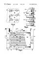
- the pipette dispensing block of the present invention 50has a head block 52 and a lift plate 54 as is common with such pipette dispensing apparatuses.
- a number of individual pistons 56slidably travel through cylindrical channels 58 according to the relative positioning of the lift plate 54 with respect to the head block 52 .
- the head block 52is maintained in a relatively stationary position and the lift plate 54 is moved vertically with respect to the head block 52 in order to control the disposition of the individual pistons 56 within the cylindrical channels 58 .
- Assorted apertures for fixation or fastening of the head block 52 to framework or other supporting structuresare shown at the lateral extremes of the head block 52 shown in FIG. 2 .
- FIG. 3shows an individual piston 56 at its juncture with the top of the head block 52 .
- FIG. 3corresponds to that portion of FIG. 2 indicated by circle 3 — 3 .
- the piston 56is circumscribed by a pair of O-rings: an upper O-ring 70 and a lower O-ring 72 .
- Circumscribing the piston 56 between the upper and lower O-ring 70 , 72is a reservoir 74 defined by the interstitial space between the head of block 52 and the piston 56 .
- This reservoir 74may be filled with grease, oil, or the like, suitably manufactured to enhance preservation of the airtight vacuum seal created by the upper and lower sealing O-rings 70 , 72 .
- Low vapor pressure silicone grease or other low pressure greases and/or oilsmay be well suited to this purpose.
- any lubricant adhering to the side of the piston 56is kept in the reservoir 74 by the upper O-ring 70 .
- the lower O-ring 72prevents lubricant adhering to the exterior of the piston 56 from traveling past it, maintaining the lubricant in the reservoir 74 .
- Some minor adherence of the grease to the exterior of the piston 56may occur, taking some miniscule portion of the grease past the O-rings.
- an airtight vacuum sealis provided about the sliding piston 56 by the upper O-ring 70 , the low vapor pressure lubricant-filled reservoir 74 and the lower O-ring 72 .
- the physical contact made between the sealing O-rings 70 , 72provides a vacuum seal which is enhanced by the low vapor pressure lubricant-filled reservoir 74 .
- the low vapor pressure lubricantmay also provide some additional resiliency and/or elasticity to the sealing O-ring 70 , preventing them from cracking and wearing.
- the lubricantmay also diminish the abrasion that may occur between the piston 56 and the O-rings 70 , 72 as the piston 56 slides past the O-rings 70 , 72 .
- the pistons 56engage the lift plate 54 by means of slats 80 .
- the pistons 56have piston heads 82 .
- the piston heads 82are separated from the other portions of the piston 56 by a piston head gap 84 , there is being a small piston head pillar 86 attaching the piston head 82 to the remainder of the piston 56 .
- FIGS. 4-6show the piston heads 82 , the slats 80 , and the engagement of the pistons 56 with the lift plate 54 . Further, FIG. 6 shows the piston shoulders 90 as they rest against the underside of the lift plate 54 . Intermediating the distance through which the piston 56 travels through the lift plate 54 , between the piston head pillar 86 and the main body portion 92 of the piston 56 , is an intermediate pillar section 94 .
- the pistons 56may be arranged in a standard 8 ⁇ 12 array so that eight dozen samples may be pipetted simultaneously.
- a top and restraining cover 100 of the lift plate 54is shown in partial cutaway view revealing the underlying pistons 56 and the exposed piston heads 82 along with the intermediating sliding slats 80 .
- the slats 80engage the pillar grooves or gaps 84 in a close manner.
- the slats 80may be removed from between the piston heads 82 by sliding them laterally.
- the slats 80are trapped between two (2) adjacent rows of pistons 56 .
- the first and last rows of pistons 56do not have other adjacent piston rows.
- slat holders 102are used that conform continuously to the grooves presented by the piston heads 82 . Consequently, the pistons 56 on the first and last rows are also held in place on either side by slats 80 as the terminal slats are also held in place on both sides (on one side by a row of piston heads 82 and on the other side by the slat holders 102 ).
- the materials used in the present inventionare generally materials easily sterilizable and chemically inert. Machined-aluminum, steel, and the like that are manufactured to close tolerances provide adequate materials and structures by which the stresses and forces arising from the use of the pipette dispensing block of the present invention may be accommodated and endured without breakage, damage, or extraordinary wear and tear. This is particularly true for the piston heads 82 where the piston head gap 84 about the piston head pillar 86 may be a point of weakness due to the thin nature of the piston head pillar 86 .
- the materials currently used in the artappear to provide adequate support and structural integrity for use in the present invention.
- the slats 80are held in place on either side by the piston heads 82 .
- the slats 80slide between the pistons 56 and are held in place by opposing pairs of piston head pillars 86 (not shown in FIG. 5, see FIGS. 2, 6 ).
- the piston head gaps 84are generally the same height as the slats 80 , or in close tolerance, only slightly exceeding such height.
- the slats 80hold the pistons 56 in place as the lift plate 54 lifts up and away from the head block 52 .
- the lift plate 54presses down against the piston shoulders 90 in order to drive the piston forward and into the cylindrical channel 58 . Consequently, the intermediate piston section 94 of the piston 56 is trapped inside the lift plate 54 .
- the piston 56cannot move to the right past the lift plate 54 as the shoulder 90 prevents passage of the piston through the lift plate 54 .
- the piston 56cannot move leftwardly relative to FIG. 6 through the lift plate 54 and the aperture there accommodating the intermediate pillar section 94 as the slat 80 prevents the piston head 82 from traveling to the left.
- the piston head 82may then travel through the piston aperture 104 present for each and every piston 56 in the array.
- the lift plate piston aperture 104is of a diameter generally sufficient to accommodate the intermediate piston pillar section 94 .
- the lift plate 54may have two (2) apertured plates beyond the generally solid lift plate cover 100 .
- the bottom lift plate 110may generally engage the top portion of the main piston portion 92 at the shoulder 90 .
- the plates 112 and 110may be integral as shown in FIG. 2 as opposed to separate as shown in FIG. 6 .
- an O-ringis set into the bottom portion of lower plate 110 for each of the pistons 56 in order to seat each of the pistons 56 in a resilient manner with respect to the lift plate 54 .
- the shoulder 90may then engage a more interior abutment present in the lower plate 110 .
- the upper plate 112is adjacent and above the lower plate 110 and serves to provide a foundation upon which the slats 80 may rest as they engage the piston heads 82 .
- the piston shoulders 90may engage the underside of the upper plate 112 with the lower plate 110 providing room for an O-ring gasket or the like to resiliently hold in place the individual pistons 56 .
- the grooved piston head 82 and slat 80 arrangements set forth aboveit becomes a much simpler task to engage or remove an individual piston 56 , particularly pistons that are central to an 8 ⁇ 12, 16 ⁇ 24 or other array.
- the lift plate cover 100is removed and thereby exposing the piston heads 82 and the slats 80 .
- the slats 80then slide laterally to disengage the individual piston heads 82 , the slats 80 sliding through the grooves and generally out and away from the lift plate 54 .
- the upper plate 112(FIG. 6) may then be removed from the lower plate 110 once all of the slats 80 have been removed.
- the lower plate 110is then exposed and may also be removed from the top of the pistons 56 and their array. Individual ones of the pistons 56 may then be withdrawn from the head block 52 in order to be replaced or repaired.
- the lower plate 110may then be replaced upon the piston heads 82 , with the optional gasket O-rings seating themselves in the bottom of the lower plate 110 .
- the upper plate 112may then be replaced upon the top of the piston array.
- the pistons 56may then be arranged so that the piston heads 82 protrude up and away from the upper plate 112 .
- the slats 80may then be slid back into their position between the rows of piston heads 82 , the slats 80 sliding through the close-tolerance gap defined between opposite pairs of piston head pillars 86 .
Landscapes
- Health & Medical Sciences (AREA)
- Clinical Laboratory Science (AREA)
- Chemical & Material Sciences (AREA)
- Chemical Kinetics & Catalysis (AREA)
- Sampling And Sample Adjustment (AREA)
Abstract
Description
1. Field of the Invention
This invention relates to laboratory equipment, and more particularly to a pipette dispensing block used in biologically-related laboratories that aspirates and dispenses fluid volumes in a precise and controlled manner.
2. Description of the Related Art
Recently, biology has increasingly incorporated elements of basic molecular and atomic chemistry, yielding the field of biotechnology. The secrets nature has hidden in mammalian and other biology are increasingly being unraveled and discovered. With greater knowledge of molecular biochemistry, genefic structure and effect, coupled with the ability to reproduce biologically active molecules quickly and easily, a corresponding increase in research has demanded tools and equipment that are able to promote the investigative activities related to present day biotechnology.
U.S. Pat. No. 5,525,302 issued Jun. 11, 1996 to Astle for a Method and Device for Simultaneously Transferring Plural Samples sets forth machinery by which standard samples in a standard sample container can be transferred, aspirated, and dispensed in a highly-controlled manner. The Astle '302 patent is incorporated herein by this reference hereto.
In the Astle '302 patent, a pipette system (particularly that one which is shown in FIGS. 1B and 5 of the Astle '302 patent) is disclosed relating to the construction and operation of a pipette system. As shown in FIG. 5, internal and external reservoirs may serve to control fluid flow through thehollow tube piston 50 when the clamp mechanism 140 is opened by separating the rod 146 from the anvil 142.
In the Astle '302 patent, thelift plate 52 controls the relative position of thehollow tube piston 50 in its travel inside the cylindrical channel 60. The elastomeric O-ring 62 seals the cylindrical channel 60 so that a vacuum may be pulled on thepipette tip 70, thereby allowing it to aspirate or, conversely, dispense fluid.
Note should be taken that if the elastomeric O-ring 62 breaks down through wear or otherwise does not seal the cylindrical channel 60, gases such as air can flow into the cylindrical channel 60 and thereby defeat the vacuum pulled on the cylindrical channel 60 by the motion of thelift plate 52 and thehollow tube piston 50. The same is similarly true when pressure is applied via thepiston 50.
Consequently, it can be seen that the elastomeric O-ring 62 is a weak link in the Astle '302 patent system. This weak link is known in the art and is currently addressed by the application of grease, oil, or the like adjacent the elastomeric O-ring 62 as it suffers wear, tear, abrasion, and deterioration throughout the useful life of the elastomeric O-ring 62.
The opposite end of the cylindrical channel 60 is sealed by thepipette tip 70 and a second sealing O-ring 66 in conjunction with the hollow cylindrical pin extension 64. FIG. 5 of the Astle '302 patent shows all these features.
Additionally, FIG. 5 of the Astle '302 patent shows the use of retainingrings hollow tube piston 50. As thehollow tube piston 50 forms one of ninety-six (96) such hollow tube pistons in an 8×12 array of such pistons, it becomes a daunting, time-consuming, and tedious task to replace one or several of thehollow tube pistons 50. Additionally, in order to remove one single piston such as a central one of thehollow tube pistons 50, theentire lift plate 52 may be required to be lifted up and away from thehead block 40. This causes each and every one of thehollow tube pistons 50 to be disengaged from thehead block 40, breaking the seal formed in conjunction with the elastomeric O-ring seal 62. The retainingrings
Consequently, it can be seen that the use of retaining rings (such as those indicated byreference numbers
Other developments in the pipette dispensing art are known and are indicated in summary fashion below.
U.S. Pat. No. 4,087,248 issued to Miles on May 2, 1978 for a Multiple Assay Machine and Method has a motor-driven housing and a syringe battery. An upper platform is mounted on threaded bolts so as to be capable of vertical movement with the turning of the bolts. A retaining syringe plunger plate is secured to an upper platform. The syringe battery has a rectangular housing with an upper guide plate mounted on a housing ceiling having a plurality of channels for guiding plungers. The syringe plunger plate has a hollow center for receiving the plunger heads and holding them in a fixed position. To perform an immunoassay, the syringe battery is introduced into the motor driven housing by sliding the syringe plunger plate between the L-shaped arms of the upper platform.
U.S. Pat. No. 4,106,911 issued to Marcelli on Aug. 15, 1978 for a Device for Examining a Plurality of Microdoses of Liquid is a dispenser of micro-doses of liquids having a base plate with a frame having a vertical arm. A motor is provided with a vertical screw arranged to position a slide block having an extension in the form of a horizontal plate with which the ends of plunger rods of syringes are made fast by means of clips. The bodies of the syringes are made fast with a support. When the motor is running, it moves a nut along a screw and varies the distance between a plate (indicated by reference number 11) and a support, thus enabling the plunger rods to move inside the bodies of all the syringes.
U.S. Pat. No. 4,602,517 issued to Schultz on Jul. 29, 1986 for a Fluid Sampling Method and Apparatus contains a multiple syringe dispenser having a central block assembly, an actuator assembly, and a syringe clamp assembly. Block members of the clamping assembly have protective frictional pads affixed to the V-shaped slots to delicately grip the handles of syringe tubes. The block and actuator assembly provides for the intermittent moving of a drive rod that raises a syringe plunger support assembly having lower and upper plates. Slots in the lower plate allow the insertion of a plunger member whereby the enlarged disk-like ends of the plungers are held by a cushioning pad extending the length of the upper and lower plates. Plungers fit into a cylinder of the syringe and the plungers can all be raised or lowered simultaneously by means of the actuator. A thermally-releasable sample collecting device has an absorber tube with its small diameter front end supported by a locating collar having two (2) O-ring seals. A rearward locating collar has O-ring seals for supporting the larger diameter rear end portion of the absorber tube.
U.S. Pat. No. 5,497,670 issued to Carl on Mar. 12, 1996 for a Liquid Dispensing Apparatus Including Means for Loading Pipette Tips onto Liquid Dispensing Cylinders and Maintaining the Loading Force During the Apparatus Operation Cycle is directed to an apparatus for dispensing controlled amounts of liquid into receptacles. The apparatus has a plurality of plate members either fixed or movable for supporting and dispensing liquids through disposable pipette tips. Fixed cylinders and a cylinder plate are attached to a cylinder mounting plate fixed to shafts. Pistons move in a vertical direction within the fixed cylinders. Each piston passes through a Teflon® seal. The pistons are connected to a piston plate using a ball and socket mechanism to provide accurate alignment. Each piston is allowed to swivel from the center point of the ball joint. The ball ends of the pistons are attached to a movable piston plate. The piston and cylinder assembly can be removed from the apparatus with the piston plate fixed to a larger plate that slides up and down along the shafts.
Despite the foregoing development and advances in the pipette dispensing art, it remains a problem in the art, solved by the present invention, to maintain a proper vacuum seal for sliding pipette pistons as well as providing convenient and well-engineered components by which a lifting plate for such pipette pistons can have such pistons easily mounted and dismounted (attached and detached) to it.
The present invention remedies shortcomings and drawbacks found in the prior art by better preserving the airtight nature of the cylindrical channels through which hollow tube or other pistons move in a pipette block assembly. As set forth above, the preservation of the airtight seal is important to preserve the vacuum and pressure differential by which liquids may be aspirated or dispensed. As the volumes of fluids are often extremely small, in the micro-liter amounts, the preservation of an airtight seal and the vacuum pressure differential is an important feature of pipette dispensing apparatus.
In order to achieve this better airtight seal, a pair of offset O-rings is used near the go top of the head block where the piston enters into it. Between the two sealing O-rings, a reservoir is created which is filled with oil, grease, or the like to both lubricate the piston as well as to enhance the seal. With the foregoing system, the abrasion experienced by the single sealing O-ring in the Astle '302 patent (deteriorating the O-ring and its ability to maintain an airtight seal) is overcome by lowering the abrasion experienced by the dual sealing O-ring and by better preserving the airtight nature of the contact between the head block and the piston.
Additionally, as the pistons may require maintenance or the like, and in order to control single rows (and perhaps single columns) of pistons, the piston heads are grooved to receive a sliding slat that interconnects the individual pistons and forces them to move with the lifting plate. In order to disengage the lifting plate from the piston heads, the slats are removed by sliding them laterally and the lifting plate is removed from the array of piston heads. The ends of the pistons, adjacent to the grooved piston heads, have an outwardly circumferential shoulder that engages the underside of one of the lifting plate portions. The individual pistons are then trapped by one or more of the lifting plate portions as a part of the lifting plate is trapped between the groove-engaging slat and the pistons' outward shoulders.
By engraving the piston heads so that they are grooved to engage the slats, and by providing the outward shoulders, convenient means (greatly exceeding that of single or dual retaining rings) are provided by which the lifting plate may be disengaged from the pistons and individual piston rows may be disabled or disengaged from the lifting plate.
It is an object of the present invention to provide a better seal for pipette pistons in a pipette dispensing block.
It is another object of the present invention to provide easily engagable and disengagable engaging means by which pipette piston heads may be associated and attached to a lifting plate.
It is another object of the present invention to provide a more resilient and longer lasting vacuum seal between a pipette piston and its head block.
These and other objects of and advantages of the present invention will be apparent from a review of the following specification and accompanying drawings.
FIG. 1 is a side plan and partial cutaway view of a pipette piston dispensing arrangement corresponding closely to a significant portion of FIG. 5 in U.S. Pat. No. 5,525,302 issued to Astle on Jun. 11, 1996.
FIG. 2 is a side plan and partial cutaway view of the pipette dispensing block of the present invention showing the head block and individual pistons in their cylindrical channels.
FIG. 3 is a partial cutaway and close-up view of the head block-piston interface corresponding to circle3—3 in FIG.2.
FIG. 4 is an overhead plan and partial cutaway view of the pipette dispenser of the present invention, the cutaway view showing the lift plate, the slats, and individual piston heads held thereby;
FIG. 5 is a partial and enlarged view of the piston head array with the groove-engaging slats intermediating individual piston heads corresponding tocircle 5—5 of FIG. 4;
FIG. 6 is a side plan and partial cutaway view of the lifting plate shown in FIG. 4 taken alongline 6—6.
The detailed description set forth below in connection with the appended drawings is intended as a description of presently preferred embodiments of the invention and is not intended to represent the only forms in which the present invention may be constructed, used, and/or utilized. The description herein sets forth the functions and the sequence of steps for constructing and operating the invention in connection with the illustrated embodiments. However, it is to be understood that the same or equivalent funtions and sequences may be accomplished by different embodiments that are also intended to be encompassed within the spirit and scope of the invention.
The shortcomings in the prior art are illustrated by FIG. 1 which corresponds in significant portion to FIG. 5 of the U.S. Pat. No. 5,525,302 issued to Astle on Jun. 11, 1996 (the “Astle '302 patent”). In FIG. 1, the Astle '302 patentpipette dispensing apparatus 20 is shown.
In FIG. 1, aflexible tube 22 leads into ahollow transition piece 24 which enters into thehollow tube piston 26. Thehollow tube piston 26 is held in place by alift plate 28 by upper and lower retaining rings30,32.
Thehollow tube piston 26 moves into and out of thehead block 34 at acylindrical channel 36. A sealing O-ring 38 serves to seal thecylindrical channel 36 and its upper end To where thehollow tube piston 26 moves into and out of thehead block 34.
A hollowcylindrical pin extension 40 engages apipette tip 42 having anopen end 46. Thepipette tip 42 is often used in conjunction with asample tray 44 in order to aspirate or dispense precise amounts of fluid.
As can be seen from FIG. 1, it is theopen end 46 of thepipette tip 42 that allows for extraction or injection of fluid from thecylindrical channel 36 as controlled by thehollow cylinder piston 26. Thehollow cylinder piston 26 may also be solid, however, in the Astle '302 patent, additional features were provided by such a hollow tube piston in conjunction with one or more reservoirs of fluid.
The ability to extract or aspirate fluid from thesample tray 44 is dependent upon the seal created by the sealing O-ring 38. As thepiston 26 is withdrawn from thecylindrical channel 36, a pressure differential is created thereby forcing fluid from thesample tray 44 through thepipette tip 42 and ultimately into thecylindrical channel 36. If the seal provided by sealing O-ring 38 lacks integrity, leaks, or otherwise fails, the withdrawal of thepiston 26 from thecylindrical channel 36 does not aspirate fluid from thesample tray 44. Instead, it pulls air into thecylindrical channel 36 past the sealing O-ring 38. Consequently, it is of great importance to make sure that the seal provided adjacent the top of thehead block 34 with respect to thecylindrical channel 36 and in conjunction with thepiston 26, maintains its integrity for the greatest amount of time in order to provide a longer useful life and better reliability for proper extraction and ejection of fluids.
Additionally, it can be seen that the upper and lower retaining rings30,32 provide difficult means by which thepiston 26 is attached to thelift plate 28. While such retaining rings30,32 are convenient when used for anindividual plunger 26, commonly,such plungers 26 are set forth in arrays of ninety-six (96) (8×12) which creates difficult spacing requirements in reaching the retaining rings, particularly forpistons 26 generally centrally located in the array. In fact, the other adjacent retaining rings30,32 andpistons 26 may need to be removed or moved in order to reach the particular piston of interest. It would be much better to provide a more convenient and simple means by which individual pistons can be disengaged from thelift plate 28 so that they may be adjusted, maintained, or fixed. Also such means could provide a better way to allow replacement or substitution oflift plates 28 orpistons 26.
The present invention is shown in partial view in FIG.2. In FIG. 2, the pipette dispensing block of thepresent invention 50 has ahead block 52 and alift plate 54 as is common with such pipette dispensing apparatuses. A number ofindividual pistons 56 slidably travel throughcylindrical channels 58 according to the relative positioning of thelift plate 54 with respect to thehead block 52. Generally thehead block 52 is maintained in a relatively stationary position and thelift plate 54 is moved vertically with respect to thehead block 52 in order to control the disposition of theindividual pistons 56 within thecylindrical channels 58. Assorted apertures for fixation or fastening of thehead block 52 to framework or other supporting structures are shown at the lateral extremes of thehead block 52 shown in FIG.2.
FIG. 3 shows anindividual piston 56 at its juncture with the top of thehead block 52. FIG. 3 corresponds to that portion of FIG. 2 indicated by circle3—3.
As shown in FIG. 3, thepiston 56 is circumscribed by a pair of O-rings: an upper O-ring 70 and a lower O-ring 72. Circumscribing thepiston 56 between the upper and lower O-ring reservoir 74 defined by the interstitial space between the head ofblock 52 and thepiston 56. Thisreservoir 74 may be filled with grease, oil, or the like, suitably manufactured to enhance preservation of the airtight vacuum seal created by the upper and lower sealing O-rings
As thepiston 56 slides upwardly or downwardly past the sealing O-rings reservoir 74, the sides of thepiston 56 are snugly engaged by the O-rings reservoir 74 by the O-rings piston 56 travels upwardly and downwardly past thereservoir 74.
When thepiston 56 travels upwardly, any lubricant adhering to the side of thepiston 56 is kept in thereservoir 74 by the upper O-ring 70. As the piston travels downwardly, the lower O-ring 72 prevents lubricant adhering to the exterior of thepiston 56 from traveling past it, maintaining the lubricant in thereservoir 74. Some minor adherence of the grease to the exterior of thepiston 56 may occur, taking some miniscule portion of the grease past the O-rings.
In this way, an airtight vacuum seal is provided about the slidingpiston 56 by the upper O-ring 70, the low vapor pressure lubricant-filledreservoir 74 and the lower O-ring 72. The physical contact made between the sealing O-rings reservoir 74. Beyond providing a viscous mechanical layer helping to preserve the seal, the low vapor pressure lubricant may also provide some additional resiliency and/or elasticity to the sealing O-ring 70, preventing them from cracking and wearing. The lubricant may also diminish the abrasion that may occur between thepiston 56 and the O-rings piston 56 slides past the O-rings
As set forth in further detail below, thepistons 56 engage thelift plate 54 by means ofslats 80. As shown in FIG. 2, thepistons 56 have piston heads82. The piston heads82 are separated from the other portions of thepiston 56 by apiston head gap 84, there is being a smallpiston head pillar 86 attaching thepiston head 82 to the remainder of thepiston 56.
FIGS. 4-6 show the piston heads82, theslats 80, and the engagement of thepistons 56 with thelift plate 54. Further, FIG. 6 shows the piston shoulders90 as they rest against the underside of thelift plate 54. Intermediating the distance through which thepiston 56 travels through thelift plate 54, between thepiston head pillar 86 and themain body portion 92 of thepiston 56, is anintermediate pillar section 94.
As shown in FIG. 4, thepistons 56 may be arranged in a standard 8×12 array so that eight dozen samples may be pipetted simultaneously. A top and restrainingcover 100 of thelift plate 54 is shown in partial cutaway view revealing theunderlying pistons 56 and the exposed piston heads82 along with theintermediating sliding slats 80.
Theslats 80 engage the pillar grooves orgaps 84 in a close manner. When thelift plate cover 100 is removed, theslats 80 may be removed from between the piston heads82 by sliding them laterally. Generally, theslats 80 are trapped between two (2) adjacent rows ofpistons 56. However, at the upper and lower ends (relative to FIG.4), the first and last rows ofpistons 56 do not have other adjacent piston rows.
Consequently,slat holders 102 are used that conform continuously to the grooves presented by the piston heads82. Consequently, thepistons 56 on the first and last rows are also held in place on either side byslats 80 as the terminal slats are also held in place on both sides (on one side by a row of piston heads82 and on the other side by the slat holders102).
Due to the accuracy required in pipetting samples with pipette dispensers, the materials used in the present invention are generally materials easily sterilizable and chemically inert. Machined-aluminum, steel, and the like that are manufactured to close tolerances provide adequate materials and structures by which the stresses and forces arising from the use of the pipette dispensing block of the present invention may be accommodated and endured without breakage, damage, or extraordinary wear and tear. This is particularly true for the piston heads82 where thepiston head gap 84 about thepiston head pillar 86 may be a point of weakness due to the thin nature of thepiston head pillar 86. However, the materials currently used in the art appear to provide adequate support and structural integrity for use in the present invention.
As shown in FIG. 5, theslats 80 are held in place on either side by the piston heads82. Theslats 80 slide between thepistons 56 and are held in place by opposing pairs of piston head pillars86 (not shown in FIG. 5, see FIGS. 2,6). Thepiston head gaps 84 are generally the same height as theslats 80, or in close tolerance, only slightly exceeding such height.
Theslats 80 hold thepistons 56 in place as thelift plate 54 lifts up and away from thehead block 52. When thelift plate 54 descends, in order to eject or dispense fluid held in thecylindrical channels 58, thelift plate 54 presses down against the piston shoulders90 in order to drive the piston forward and into thecylindrical channel 58. Consequently, theintermediate piston section 94 of thepiston 56 is trapped inside thelift plate 54.
As shown relative to FIG. 6, thepiston 56 cannot move to the right past thelift plate 54 as theshoulder 90 prevents passage of the piston through thelift plate 54. Thepiston 56 cannot move leftwardly relative to FIG.6 through thelift plate 54 and the aperture there accommodating theintermediate pillar section 94 as theslat 80 prevents thepiston head 82 from traveling to the left. However, once theslats 80 on both sides of thepiston head 82 are removed, thepiston head 82 may then travel through the piston aperture104 present for each and everypiston 56 in the array. The lift plate piston aperture104 is of a diameter generally sufficient to accommodate the intermediatepiston pillar section 94.
As shown in FIG. 6, thelift plate 54 may have two (2) apertured plates beyond the generally solidlift plate cover 100. Thebottom lift plate 110 may generally engage the top portion of themain piston portion 92 at theshoulder 90.
Theplates 112 and110 may be integral as shown in FIG. 2 as opposed to separate as shown in FIG.6. In the top piston, an O-ring is set into the bottom portion oflower plate 110 for each of thepistons 56 in order to seat each of thepistons 56 in a resilient manner with respect to thelift plate 54. Theshoulder 90 may then engage a more interior abutment present in thelower plate 110. The upper plate112 is adjacent and above thelower plate 110 and serves to provide a foundation upon which theslats 80 may rest as they engage the piston heads82. In the alternative embodiment, the piston shoulders90 may engage the underside of the upper plate112 with thelower plate 110 providing room for an O-ring gasket or the like to resiliently hold in place theindividual pistons 56.
By using the groovedpiston head 82 andslat 80 arrangements set forth above, it becomes a much simpler task to engage or remove anindividual piston 56, particularly pistons that are central to an 8×12, 16×24 or other array. Thelift plate cover 100 is removed and thereby exposing the piston heads82 and theslats 80. Theslats 80 then slide laterally to disengage the individual piston heads82, theslats 80 sliding through the grooves and generally out and away from thelift plate 54. The upper plate112 (FIG. 6) may then be removed from thelower plate 110 once all of theslats 80 have been removed.
As seen in FIG. 6, upon removing the upper plate112, thelower plate 110 is then exposed and may also be removed from the top of thepistons 56 and their array. Individual ones of thepistons 56 may then be withdrawn from thehead block 52 in order to be replaced or repaired. Thelower plate 110 may then be replaced upon the piston heads82, with the optional gasket O-rings seating themselves in the bottom of thelower plate 110. The upper plate112 may then be replaced upon the top of the piston array. Thepistons 56 may then be arranged so that the piston heads82 protrude up and away from the upper plate112. Theslats 80 may then be slid back into their position between the rows of piston heads82, theslats 80 sliding through the close-tolerance gap defined between opposite pairs ofpiston head pillars 86.
While the present invention has been described with regards to particular embodiments, it is recognized that additional variations of the present invention may be devised without departing from the inventive concept.
Claims (18)
1. A pipette dispensing block, comprising:
a head block, said head block defining a channel, said channel having an upper end, said head block defining a reservoir adjacent said upper channel end;
a piston, said piston slidably travelling through said channel;
a first seal, said first seal adjacent said reservoir and providing a seal between said head block and said piston; and
lubricant, said lubricant held in said reservoir; whereby
said first seal provides an airtight vacuum seal about said piston adjacent said upper channel end.
2. The pipette dispensing block of claim1, further comprising:
a second seal, said second seal adjacent said reservoir on a side opposite to that of said first seal such that the reservoir is between said first and second seals.
3. The pipette dispensing block of claim2, wherein said first and second seals further comprise O-rings.
4. The pipette dispensing block of claim3, wherein said first and second seals suffer less where and tear from said sliding piston as contact between said first and second seals is lubricated by said lubricant, whereby said vacuum seal is maintained in a better and more enduring manner.
5. The pipette dispensing block of claim4, wherein said lubricant is a low vapor pressure lubricant, whereby said lubricant does not tend to evaporate into said channel.
6. A pipette dispensing block, comprising:
a head block, said head block defining a channel, said channel having an upper end;
a piston, said piston slidably traveling through said channel;
a first seal, said first seal adjacent said upper channel end and providing a seal between said head block and said piston; and
a second seal, said second seal adjacent said first seal and providing a seal between said head block and said piston; whereby
said first and second seals provide an airtight vacuum seal about said piston adjacent said upper channel end;
said head block defining a reservoir adjacent said upper channel end, said reservoir between said first and second seals; and
lubricant, said lubricant held in said reservoir; whereby said first and second seals contain said lubricant in said reservoir.
7. The pipette dispensing block of claim6, wherein said first and second seals further comprise O-rings.
8. The pipette dispensing block of claim7, wherein said first and second seals suffer less where and tear from abrasion from said sliding piston as contact between said first and second seals is lubricated by said lubricant, said vacuum seal is maintained in a better and more enduring manner, and said lubricant serves to maintain said first and second seals in a more resilient condition.
9. The pipette dispensing block of claim8, wherein said lubricant is a low vapor pressure lubricant, whereby said lubricant does not tend to evaporate into said channel.
10. A pipette dispensing block having a lift plate, comprising:
a piston, said piston having a head and defining a head groove adjacent to said head;
a slat, said slat dimensioned in height to engage said piston head by passing through said piston groove; whereby
said piston is held in place by said piston with respect to the lift plate.
11. The pipette dispensing block having a lift plate of claim10, wherein said piston further comprises:
a shoulder, said shoulder abutting an underside of the lift plate; whereby
a lift plate portion is trapped between said slat and said shoulder, locking said piston to the lift plate.
12. The pipette dispensing block having a lift plate of claim11, further comprising:
said piston being one of several pistons in a first straight row; and
said slat slidably trapped between said first straight row and a second straight row of pistons; whereby
said pistons of said first and second straight rows are locked to the lift plate by said slat.
13. The pipette dispensing block having a lift plate of claim12, wherein the lift plate further comprises:
an upper plate, said upper plate defining an upper piston aperture through which said piston passes; and
a lower plate, said lower plate adjacent and below said upper plate, said lower plate defining a lower piston aperture through which said piston passes; whereby
said piston may be disposed by the lift plate by said upper and lower plates.
14. The pipette dispensing block having a lift plate of claim13, further comprising:
said lower plate defining a set-in or offset surrounding said piston; and
an O-ring, said O-ring sitting in said offset and engaging said piston; whereby
said piston is resiliently positioned by said O-ring in alignment with said upper and lower piston apertures.
15. The pipette dispensing block having a lift plate of claim14, further comprising:
said piston shoulder abutting said upper plate; whereby
said piston is locked to said upper plate and the lift plate by trapping the upper plate between said piston shoulder and said slat.
16. A pipette dispensing block, comprising:
a head block, said head block defining a channel, said channel having an upper end, said head block defining a reservoir adjacent said upper channel end;
a piston, said piston slidably travelling through said channel, said piston having a head and defining a head groove adjacent to said head, said piston having a shoulder, said shoulder spaced away from said piston head;
a lift plate, said lift plate having an upper plate and a lower plate, said lower plate adjacent and below said upper plate, said upper plate defining an upper piston aperture through which a first portion of said piston passes, said lower plate defining a lower piston aperture through which a second portion of said piston passes, said piston disposed by said lift plate by said upper and lower plates thereof;
a first O-ring seal, said first seal adjacent said channel reservoir and providing a seal between said head block and said piston;
a second O-ring seal, said second seal adjacent said channel reservoir on a side opposite to that of said first seal such that said channel reservoir is between said first and second seals;
a low vapor pressure lubricant, said lubricant tending not to evaporate into said channel, said lubricant held in said reservoir
a slat, said slat dimensioned in height to engage said piston head by passing through said piston groove to hold said piston in place with respect to the lift plate;
said piston shoulder abutting an underside of said lift plate to trap a portion of said lift plate between said piston shoulder and said slat, locking said piston to the lift plate;
said piston being one of several pistons in a straight row, said slat slidably trapped by said straight row so that said pistons of said straight row are releasably locked to said lift plate by said slat; whereby
said first and second seals provide an airtight vacuum seal about said piston adjacent said upper channel end and said first and second seals suffer less wear and tear from said sliding piston as contact between said first and second seals is lubricated by said lubricant, said lubricant maintaining said vacuum seal in a better and more enduring manner by providing a greater mechanical barrier preserving said airtight vacuum seal, said lubricant lubricating and reducing abrasion between said sliding piston and said first and second seals; and whereby
said slat provides convenient and easy engagement and disengagement of said piston by said lift plate.
17. The pipette dispensing block of claim16, further comprising:
said lower plate defining a set-in or offset surrounding said piston; and
an O-ring, said O-ring sitting in said offset and engaging said piston; whereby
said piston is resiliently positioned by said O-ring in alignment with said upper and lower piston apertures.
18. The pipette dispensing block of claim17, further comprising:
said piston shoulder abutting said upper plate at a bottom or lower portion thereof; whereby
said piston is locked to said upper plate and said lift plate by trapping said upper plate between said piston shoulder and said slat.
Priority Applications (1)
| Application Number | Priority Date | Filing Date | Title |
|---|---|---|---|
| US09/268,244US6258324B1 (en) | 1999-03-15 | 1999-03-15 | Pipette dispensing block |
Applications Claiming Priority (1)
| Application Number | Priority Date | Filing Date | Title |
|---|---|---|---|
| US09/268,244US6258324B1 (en) | 1999-03-15 | 1999-03-15 | Pipette dispensing block |
Publications (1)
| Publication Number | Publication Date |
|---|---|
| US6258324B1true US6258324B1 (en) | 2001-07-10 |
Family
ID=23022107
Family Applications (1)
| Application Number | Title | Priority Date | Filing Date |
|---|---|---|---|
| US09/268,244Expired - LifetimeUS6258324B1 (en) | 1999-03-15 | 1999-03-15 | Pipette dispensing block |
Country Status (1)
| Country | Link |
|---|---|
| US (1) | US6258324B1 (en) |
Cited By (38)
| Publication number | Priority date | Publication date | Assignee | Title |
|---|---|---|---|---|
| US6326212B1 (en)* | 1999-10-12 | 2001-12-04 | Arden Systems, Inc. | Membrane dispensing head apparatus and method for dispensing liquid |
| WO2002016038A1 (en)* | 2000-08-25 | 2002-02-28 | Albany Molecular Research, Inc. | Multiple well microtiter plate loading assembly and method |
| WO2002062476A1 (en)* | 2001-02-05 | 2002-08-15 | Autosplice, Inc. | Liquid pin transfer assembly with common pin bias |
| US20020159921A1 (en)* | 1997-10-14 | 2002-10-31 | A.R.T. Medical Instruments Ltd. | Method for depositing a flattened droplet on a surface and apparatus therefor, and a pump therefor |
| US20020176803A1 (en)* | 2001-05-25 | 2002-11-28 | Hamel Marc F. | Automated pipetting system |
| US6544480B1 (en)* | 1999-10-26 | 2003-04-08 | Tibotec Bvba | Device and related method for dispensing small volumes of liquid |
| US6579499B1 (en)* | 2000-05-31 | 2003-06-17 | Autosplice, Inc. | Liquid compound pin replicator with weight bias |
| US20030113233A1 (en)* | 2001-10-26 | 2003-06-19 | Elizabeth Nanthakumar | Resin dispensing device |
| US6589483B1 (en)* | 1999-07-23 | 2003-07-08 | Cosmotec Co., Ltd | Liquid dispenser |
| US6627160B2 (en)* | 2000-03-20 | 2003-09-30 | Brand Gmbh + Co. Kg | Multiple channel pipetting device |
| US6669432B2 (en) | 2001-08-13 | 2003-12-30 | Matrix Technologies Corp. | Apparatus and method for handling pipetting tip magazines |
| US20040018119A1 (en)* | 2002-07-23 | 2004-01-29 | Peter Massaro | Liquid handling tool having porous plunger |
| US20040053402A1 (en)* | 2000-12-20 | 2004-03-18 | Jacobus Stark | Preparation of fluid samples by applying pressure |
| US20040071602A1 (en)* | 2002-10-15 | 2004-04-15 | Yiu Felix H. | Pipettor head adapter |
| US20040141885A1 (en)* | 2002-02-12 | 2004-07-22 | Molecular Devices Corp. | Pipettor systems and components |
| US6780381B2 (en) | 2002-04-08 | 2004-08-24 | Felix H. Yiu | Pipettor and externally sealed pipette tip |
| US6793891B2 (en) | 2002-04-08 | 2004-09-21 | Felxi Yiu | Pipettor and externally sealed pipette tip |
| US6902702B1 (en)* | 2000-08-16 | 2005-06-07 | University Health Network | Devices and methods for producing microarrays of biological samples |
| US20060008370A1 (en)* | 2004-07-09 | 2006-01-12 | Protedyne Corporation | Liquid handling device with surface features at a seal |
| US20070207062A1 (en)* | 2006-03-03 | 2007-09-06 | Sinclair James E | Air displacement pipetter |
| US20070221684A1 (en)* | 2004-05-10 | 2007-09-27 | Bernd Steinbrenner | Device for Receiving and Dispensing Liquids |
| US7396512B2 (en) | 2003-11-04 | 2008-07-08 | Drummond Scientific Company | Automatic precision non-contact open-loop fluid dispensing |
| US7402286B2 (en)* | 2001-06-27 | 2008-07-22 | The Regents Of The University Of California | Capillary pins for high-efficiency microarray printing device |
| US20090029876A1 (en)* | 2001-06-27 | 2009-01-29 | The Regents Of The University Of California | Capillary pins for high-efficiency microarray printing device |
| US20090255949A1 (en)* | 2008-04-11 | 2009-10-15 | Pelican Group Holdings, Inc. | Pipette tip handling devices and methods |
| US20100258578A1 (en)* | 2009-04-11 | 2010-10-14 | Biotix, Inc. | Automated pipette tip loading devices and methods |
| US20110183433A1 (en)* | 2010-01-22 | 2011-07-28 | Biotix, Inc. | Pipette tips |
| USD673294S1 (en) | 2009-04-11 | 2012-12-25 | Biotix, Inc. | Pipette tip handling device component |
| USD673295S1 (en) | 2009-04-11 | 2012-12-25 | Biotix, Inc. | Automated pipette tip loading device set |
| US20130183210A1 (en)* | 2005-08-22 | 2013-07-18 | Applied Biosystems, Llc | Device and method for making discrete volumes of a first fluid in contact with a second fluid, which are immiscible with each other |
| USD697227S1 (en) | 2009-04-11 | 2014-01-07 | Biotix, Inc. | Pipette tip handling device set |
| USD699859S1 (en) | 2009-04-11 | 2014-02-18 | Biotix, Inc. | Pipette tip handling device assembly |
| US8795606B2 (en)* | 2012-05-30 | 2014-08-05 | Biotix, Inc. | Integrated pipette tip devices |
| CN110694705A (en)* | 2019-10-14 | 2020-01-17 | 山东省化工研究院 | A liquid addition and liquid extraction device convenient for U-shaped porous glass plate absorption tube |
| US10946374B2 (en) | 2017-05-17 | 2021-03-16 | Biotix, Inc. | Ergonomic pipette tips |
| CN114689488A (en)* | 2022-04-21 | 2022-07-01 | 伊尔瑞生物科技(江苏)有限公司 | Lymphocyte counting and detecting micro-fluidic device for cell analysis and method thereof |
| WO2022174178A3 (en)* | 2021-02-15 | 2022-09-15 | University Of South Florida | Systems and methods for dispensing liquids |
| US20240159790A1 (en)* | 2016-05-23 | 2024-05-16 | Becton, Dickinson And Company | Liquid dispenser with manifold mount for modular independently-actuated pipette channels |
Citations (22)
| Publication number | Priority date | Publication date | Assignee | Title |
|---|---|---|---|---|
| US3650306A (en) | 1970-09-18 | 1972-03-21 | Cooke Eng Co | Laboratory dispensing apparatus |
| US4087248A (en) | 1976-07-26 | 1978-05-02 | Miles Laughton E | Multiple assay machine and method |
| US4106911A (en) | 1976-07-09 | 1978-08-15 | Societe Francaise Pour Le Developpement De L'automatisme En Biologie | Device for examining a plurality of microdoses of liquids |
| US4258761A (en) | 1979-05-03 | 1981-03-31 | Bennett John T Jr | Rehydrator |
| US4459864A (en) | 1981-10-19 | 1984-07-17 | Electro-Nucleonics, Inc. | Fluid loading and dispensing device |
| US4498510A (en) | 1982-08-20 | 1985-02-12 | Minshew Jr Edward C | Device for drawing, holding and dispensing liquid |
| US4599220A (en) | 1982-02-16 | 1986-07-08 | Yonkers Edward H | Multi-channel pipetter |
| US4602517A (en) | 1985-02-11 | 1986-07-29 | Schultz Harold R | Fluid sampling method and apparatus |
| US4607526A (en) | 1984-12-21 | 1986-08-26 | Allied Corporation | Particle analysis system |
| US4675163A (en)* | 1986-03-25 | 1987-06-23 | Mybeck Jessica F | Laboratory device |
| US4903765A (en) | 1989-01-06 | 1990-02-27 | Halliburton Company | Delayed opening fluid sampler |
| US4957706A (en) | 1986-05-22 | 1990-09-18 | Centre National De La Recherche Scientifique | Device for preserving sterility during sampling from culture medium containers |
| US5021217A (en)* | 1988-12-20 | 1991-06-04 | Nichiryo Co., Ltd. | Multipipet |
| US5061449A (en)* | 1989-07-25 | 1991-10-29 | Matrix Technologies, Corp. | Expandable multi-channel pipetter |
| US5181427A (en) | 1990-05-02 | 1993-01-26 | National Research Council Of Canada | Thermally-releasable-sample collecting device |
| US5403554A (en) | 1993-04-22 | 1995-04-04 | Freeman; Michael J. | Apparatus for depositing fluids on a chromatography plate |
| US5497670A (en) | 1995-03-31 | 1996-03-12 | Carl; Richard A. | Liquid dispensing apparatus including means for loading pipette tips onto liquid dispensing cylinders and maintaining the loading force during the apparatus operation cycle |
| US5525302A (en)* | 1991-02-01 | 1996-06-11 | Astle; Thomas W. | Method and device for simultaneously transferring plural samples |
| US5663511A (en) | 1994-08-10 | 1997-09-02 | Houilleres Du Bassin De Lorraine | Method and device for taking samples of liquids with different viscosities from a drum or other container |
| US5770160A (en)* | 1995-09-15 | 1998-06-23 | Bio-Plas, Inc. | Positive displacement liquid drawing and dispensing apparatus |
| US5958343A (en)* | 1997-12-29 | 1999-09-28 | Astle; Thomas W. | Small volume pipettor |
| US6143252A (en)* | 1999-04-12 | 2000-11-07 | The Perkin-Elmer Corporation | Pipetting device with pipette tip for solid phase reactions |
- 1999
- 1999-03-15USUS09/268,244patent/US6258324B1/ennot_activeExpired - Lifetime
Patent Citations (22)
| Publication number | Priority date | Publication date | Assignee | Title |
|---|---|---|---|---|
| US3650306A (en) | 1970-09-18 | 1972-03-21 | Cooke Eng Co | Laboratory dispensing apparatus |
| US4106911A (en) | 1976-07-09 | 1978-08-15 | Societe Francaise Pour Le Developpement De L'automatisme En Biologie | Device for examining a plurality of microdoses of liquids |
| US4087248A (en) | 1976-07-26 | 1978-05-02 | Miles Laughton E | Multiple assay machine and method |
| US4258761A (en) | 1979-05-03 | 1981-03-31 | Bennett John T Jr | Rehydrator |
| US4459864A (en) | 1981-10-19 | 1984-07-17 | Electro-Nucleonics, Inc. | Fluid loading and dispensing device |
| US4599220A (en) | 1982-02-16 | 1986-07-08 | Yonkers Edward H | Multi-channel pipetter |
| US4498510A (en) | 1982-08-20 | 1985-02-12 | Minshew Jr Edward C | Device for drawing, holding and dispensing liquid |
| US4607526A (en) | 1984-12-21 | 1986-08-26 | Allied Corporation | Particle analysis system |
| US4602517A (en) | 1985-02-11 | 1986-07-29 | Schultz Harold R | Fluid sampling method and apparatus |
| US4675163A (en)* | 1986-03-25 | 1987-06-23 | Mybeck Jessica F | Laboratory device |
| US4957706A (en) | 1986-05-22 | 1990-09-18 | Centre National De La Recherche Scientifique | Device for preserving sterility during sampling from culture medium containers |
| US5021217A (en)* | 1988-12-20 | 1991-06-04 | Nichiryo Co., Ltd. | Multipipet |
| US4903765A (en) | 1989-01-06 | 1990-02-27 | Halliburton Company | Delayed opening fluid sampler |
| US5061449A (en)* | 1989-07-25 | 1991-10-29 | Matrix Technologies, Corp. | Expandable multi-channel pipetter |
| US5181427A (en) | 1990-05-02 | 1993-01-26 | National Research Council Of Canada | Thermally-releasable-sample collecting device |
| US5525302A (en)* | 1991-02-01 | 1996-06-11 | Astle; Thomas W. | Method and device for simultaneously transferring plural samples |
| US5403554A (en) | 1993-04-22 | 1995-04-04 | Freeman; Michael J. | Apparatus for depositing fluids on a chromatography plate |
| US5663511A (en) | 1994-08-10 | 1997-09-02 | Houilleres Du Bassin De Lorraine | Method and device for taking samples of liquids with different viscosities from a drum or other container |
| US5497670A (en) | 1995-03-31 | 1996-03-12 | Carl; Richard A. | Liquid dispensing apparatus including means for loading pipette tips onto liquid dispensing cylinders and maintaining the loading force during the apparatus operation cycle |
| US5770160A (en)* | 1995-09-15 | 1998-06-23 | Bio-Plas, Inc. | Positive displacement liquid drawing and dispensing apparatus |
| US5958343A (en)* | 1997-12-29 | 1999-09-28 | Astle; Thomas W. | Small volume pipettor |
| US6143252A (en)* | 1999-04-12 | 2000-11-07 | The Perkin-Elmer Corporation | Pipetting device with pipette tip for solid phase reactions |
Cited By (79)
| Publication number | Priority date | Publication date | Assignee | Title |
|---|---|---|---|---|
| US20020159921A1 (en)* | 1997-10-14 | 2002-10-31 | A.R.T. Medical Instruments Ltd. | Method for depositing a flattened droplet on a surface and apparatus therefor, and a pump therefor |
| US6589483B1 (en)* | 1999-07-23 | 2003-07-08 | Cosmotec Co., Ltd | Liquid dispenser |
| US6326212B1 (en)* | 1999-10-12 | 2001-12-04 | Arden Systems, Inc. | Membrane dispensing head apparatus and method for dispensing liquid |
| US6544480B1 (en)* | 1999-10-26 | 2003-04-08 | Tibotec Bvba | Device and related method for dispensing small volumes of liquid |
| US20030118484A1 (en)* | 1999-10-26 | 2003-06-26 | Franck Velghe | Device and related method for dispensing small volumes of liquid |
| US6627160B2 (en)* | 2000-03-20 | 2003-09-30 | Brand Gmbh + Co. Kg | Multiple channel pipetting device |
| US6579499B1 (en)* | 2000-05-31 | 2003-06-17 | Autosplice, Inc. | Liquid compound pin replicator with weight bias |
| US6610253B2 (en)* | 2000-05-31 | 2003-08-26 | Autosplice, Inc. | Liquid pin transfer assembly with common pin bias |
| US6902702B1 (en)* | 2000-08-16 | 2005-06-07 | University Health Network | Devices and methods for producing microarrays of biological samples |
| US6406670B1 (en)* | 2000-08-25 | 2002-06-18 | Albany Molecular Research, Inc. | Multiple well microtiter plate loading assembly and method |
| WO2002016038A1 (en)* | 2000-08-25 | 2002-02-28 | Albany Molecular Research, Inc. | Multiple well microtiter plate loading assembly and method |
| US20040053402A1 (en)* | 2000-12-20 | 2004-03-18 | Jacobus Stark | Preparation of fluid samples by applying pressure |
| WO2002062476A1 (en)* | 2001-02-05 | 2002-08-15 | Autosplice, Inc. | Liquid pin transfer assembly with common pin bias |
| US6982063B2 (en) | 2001-05-25 | 2006-01-03 | Matrix Technologies Corp | Automated pipetting system |
| US20020176803A1 (en)* | 2001-05-25 | 2002-11-28 | Hamel Marc F. | Automated pipetting system |
| WO2002096562A1 (en)* | 2001-05-25 | 2002-12-05 | Matrix Technologies Corp. | Automated pipetting system |
| US20090029876A1 (en)* | 2001-06-27 | 2009-01-29 | The Regents Of The University Of California | Capillary pins for high-efficiency microarray printing device |
| US7402286B2 (en)* | 2001-06-27 | 2008-07-22 | The Regents Of The University Of California | Capillary pins for high-efficiency microarray printing device |
| US8283181B2 (en) | 2001-06-27 | 2012-10-09 | The Regents Of The University Of California | Capillary pins for high-efficiency microarray printing device |
| US6669432B2 (en) | 2001-08-13 | 2003-12-30 | Matrix Technologies Corp. | Apparatus and method for handling pipetting tip magazines |
| WO2003035239A3 (en)* | 2001-10-26 | 2003-10-16 | Sequenom Inc | Resin dispensing device |
| US20030113233A1 (en)* | 2001-10-26 | 2003-06-19 | Elizabeth Nanthakumar | Resin dispensing device |
| EP1451674A4 (en)* | 2001-10-26 | 2008-08-20 | Sequenom Inc | METHOD AND DEVICE FOR THE PARALLEL OUTPUT DEFINED VOLUMES OF SOLID PARTICLES |
| US7159740B2 (en) | 2001-10-26 | 2007-01-09 | Sequenom, Inc. | Method and apparatus for parallel dispensing of defined volumes of solid particles |
| US20030111494A1 (en)* | 2001-10-26 | 2003-06-19 | Sequenom, Inc. | Method and apparatus for high-throughput sample handling process line |
| US20030124735A1 (en)* | 2001-10-26 | 2003-07-03 | Sequenom, Inc. | Method and apparatus for parallel dispensing of defined volumes of solid particles |
| US20040141885A1 (en)* | 2002-02-12 | 2004-07-22 | Molecular Devices Corp. | Pipettor systems and components |
| US20040234420A1 (en)* | 2002-04-08 | 2004-11-25 | Yiu Felxi H. | Pipettor and externally sealed pipette tips |
| US6793891B2 (en) | 2002-04-08 | 2004-09-21 | Felxi Yiu | Pipettor and externally sealed pipette tip |
| US6780381B2 (en) | 2002-04-08 | 2004-08-24 | Felix H. Yiu | Pipettor and externally sealed pipette tip |
| US20040018119A1 (en)* | 2002-07-23 | 2004-01-29 | Peter Massaro | Liquid handling tool having porous plunger |
| US7438857B2 (en) | 2002-07-23 | 2008-10-21 | Protedyne Corporation | Liquid handling tool having porous plunger |
| US20040071602A1 (en)* | 2002-10-15 | 2004-04-15 | Yiu Felix H. | Pipettor head adapter |
| US7396512B2 (en) | 2003-11-04 | 2008-07-08 | Drummond Scientific Company | Automatic precision non-contact open-loop fluid dispensing |
| US20100252579A1 (en)* | 2004-05-10 | 2010-10-07 | Bernd Steinbrenner | Device for receiving and dispensing liquids |
| US20070221684A1 (en)* | 2004-05-10 | 2007-09-27 | Bernd Steinbrenner | Device for Receiving and Dispensing Liquids |
| US8685342B2 (en)* | 2004-05-10 | 2014-04-01 | Bernd Steinbrenner | Device for receiving and dispensing liquids |
| US20060008370A1 (en)* | 2004-07-09 | 2006-01-12 | Protedyne Corporation | Liquid handling device with surface features at a seal |
| US7246551B2 (en) | 2004-07-09 | 2007-07-24 | Protedyne Corporation | Liquid handling device with surface features at a seal |
| WO2006017186A1 (en)* | 2004-07-09 | 2006-02-16 | Protedyne Corporation | Liquid handling device with surface features at a seal |
| US11162137B2 (en) | 2005-08-22 | 2021-11-02 | Applied Biosystems Llc | Apparatus, system, and method using immiscible-fluid-discrete-volumes |
| US10041113B2 (en) | 2005-08-22 | 2018-08-07 | Applied Biosystems, Llc | Apparatus, system, and method using immiscible-fluid-discrete-volumes |
| US12435367B2 (en) | 2005-08-22 | 2025-10-07 | Applied Biosystems, Llc | Apparatus, system, and method using immiscible-fluid-discrete-volumes |
| US20130183210A1 (en)* | 2005-08-22 | 2013-07-18 | Applied Biosystems, Llc | Device and method for making discrete volumes of a first fluid in contact with a second fluid, which are immiscible with each other |
| US10450604B2 (en) | 2005-08-22 | 2019-10-22 | Applied Biosystems, Llc | Device and method for making discrete volumes of a first fluid in contact with a second fluid, which are immiscible with each other |
| US9140630B2 (en)* | 2005-08-22 | 2015-09-22 | Applied Biosystems, Llc | Device and method for making discrete volumes of a first fluid in contact with a second fluid, which are immiscible with each other |
| US11319585B2 (en) | 2005-08-22 | 2022-05-03 | Applied Biosystems, Llc | Device and method for making discrete volumes of a first fluid in contact with a second fluid, which are immiscible with each other |
| US20070207062A1 (en)* | 2006-03-03 | 2007-09-06 | Sinclair James E | Air displacement pipetter |
| US7919047B2 (en)* | 2006-03-03 | 2011-04-05 | Vertex Pharmaceuticals Incorporated | Air displacement pipetter |
| US9505006B2 (en) | 2008-04-11 | 2016-11-29 | Biotix, Inc. | Pipette tip handling devices and methods |
| US8460622B2 (en) | 2008-04-11 | 2013-06-11 | Biotix, Inc. | Pipette tip handling devices and methods |
| US9238227B2 (en) | 2008-04-11 | 2016-01-19 | Biotix, Inc. | Pipette tip handling devices and methods |
| US20090255949A1 (en)* | 2008-04-11 | 2009-10-15 | Pelican Group Holdings, Inc. | Pipette tip handling devices and methods |
| USD673295S1 (en) | 2009-04-11 | 2012-12-25 | Biotix, Inc. | Automated pipette tip loading device set |
| USD699859S1 (en) | 2009-04-11 | 2014-02-18 | Biotix, Inc. | Pipette tip handling device assembly |
| USD697227S1 (en) | 2009-04-11 | 2014-01-07 | Biotix, Inc. | Pipette tip handling device set |
| US8590736B2 (en)* | 2009-04-11 | 2013-11-26 | Biotix, Inc. | Automated pipette tip loading devices and methods |
| USD673294S1 (en) | 2009-04-11 | 2012-12-25 | Biotix, Inc. | Pipette tip handling device component |
| US20100258578A1 (en)* | 2009-04-11 | 2010-10-14 | Biotix, Inc. | Automated pipette tip loading devices and methods |
| US9486803B2 (en) | 2010-01-22 | 2016-11-08 | Biotix, Inc. | Pipette tips |
| US10828633B2 (en) | 2010-01-22 | 2020-11-10 | Biotix, Inc. | Pipette tips |
| US20110183433A1 (en)* | 2010-01-22 | 2011-07-28 | Biotix, Inc. | Pipette tips |
| US11590490B2 (en) | 2010-01-22 | 2023-02-28 | Biotix, Inc. | Pipette tips |
| US10307753B2 (en) | 2010-01-22 | 2019-06-04 | Biotix, Inc. | Pipette tips |
| US9636672B2 (en) | 2010-01-22 | 2017-05-02 | Biotix, Inc. | Pipette tips |
| US9101923B2 (en) | 2010-01-22 | 2015-08-11 | Biotix, Inc. | Pipette tips |
| US11433389B2 (en) | 2012-05-30 | 2022-09-06 | Biotix, Inc. | Integrated pipette tip devices |
| US10654037B2 (en) | 2012-05-30 | 2020-05-19 | Biotix, Inc. | Integrated pipette tip devices |
| US8795606B2 (en)* | 2012-05-30 | 2014-08-05 | Biotix, Inc. | Integrated pipette tip devices |
| US9302262B2 (en) | 2012-05-30 | 2016-04-05 | Biotix, Inc. | Integrated pipette tip devices |
| US9597680B2 (en) | 2012-05-30 | 2017-03-21 | Biotix, Inc. | Integrated pipette tip devices |
| US9884319B2 (en) | 2012-05-30 | 2018-02-06 | Biotix, Inc. | Integrated pipette tip devices |
| US20240159790A1 (en)* | 2016-05-23 | 2024-05-16 | Becton, Dickinson And Company | Liquid dispenser with manifold mount for modular independently-actuated pipette channels |
| US12345729B2 (en)* | 2016-05-23 | 2025-07-01 | Becton, Dickinson And Company | Liquid dispenser with manifold mount for modular independently-actuated pipette channels |
| US10946374B2 (en) | 2017-05-17 | 2021-03-16 | Biotix, Inc. | Ergonomic pipette tips |
| US12053771B2 (en) | 2017-05-17 | 2024-08-06 | Biotix, Inc. | Ergonomic pipette tips |
| CN110694705A (en)* | 2019-10-14 | 2020-01-17 | 山东省化工研究院 | A liquid addition and liquid extraction device convenient for U-shaped porous glass plate absorption tube |
| WO2022174178A3 (en)* | 2021-02-15 | 2022-09-15 | University Of South Florida | Systems and methods for dispensing liquids |
| CN114689488A (en)* | 2022-04-21 | 2022-07-01 | 伊尔瑞生物科技(江苏)有限公司 | Lymphocyte counting and detecting micro-fluidic device for cell analysis and method thereof |
Similar Documents
| Publication | Publication Date | Title |
|---|---|---|
| US6258324B1 (en) | Pipette dispensing block | |
| US4086060A (en) | Disposable manipulative laboratory device for transferring biological fluids | |
| US6978689B2 (en) | Dispensing apparatus having means for loading pipette tips in a dispense head | |
| US6793891B2 (en) | Pipettor and externally sealed pipette tip | |
| US6589483B1 (en) | Liquid dispenser | |
| US5497670A (en) | Liquid dispensing apparatus including means for loading pipette tips onto liquid dispensing cylinders and maintaining the loading force during the apparatus operation cycle | |
| EP1074302B1 (en) | Multichannel pipette system and pipette tips therefor | |
| US6824024B2 (en) | Device for the take-up and/or release of liquid samples | |
| EP0758923B1 (en) | Apparatus and method for a highly parallel pipetter | |
| US20060034732A1 (en) | Pipetting device | |
| US6959615B2 (en) | Sample collection and processing device | |
| US20110319300A1 (en) | Systems for Filling a Sample Array by Droplet Dragging | |
| EP3597728A1 (en) | Cell transfer device and cell transfer method | |
| US6240984B1 (en) | Foot seal for liquid handler | |
| US20110132109A1 (en) | Device and process for the formation of microdepositions | |
| AU3378600A (en) | Syringe array system and method | |
| JPS621459A (en) | Device for adapting majority pipet operating position to different state | |
| US7001774B1 (en) | Sample collection and processing device | |
| WO2002045857A2 (en) | Self-aligning nozzle array for pipette tip array plate | |
| EP1174701B1 (en) | Sample collection and processing device | |
| US20230393105A1 (en) | Support fixture for chromatography columns | |
| JPH08117618A (en) | Liquid dispensing device | |
| CN212237349U (en) | Liquid transfer equipment | |
| EP4202444B1 (en) | Multi-channel pipetting head | |
| CN221191487U (en) | PCR test tube switch cover device |
Legal Events
| Date | Code | Title | Description |
|---|---|---|---|
| AS | Assignment | Owner name:TRANSAMERICA BUSINESS CREDIT CORPORATION, ILLINOIS Free format text:SECURITY AGREEMENT;ASSIGNOR:SS8 NETWORKS, INC.;REEL/FRAME:011279/0839 Effective date:20000912 | |
| AS | Assignment | Owner name:SS8 NETWORKS, INC., CALIFORNIA Free format text:TERMINATION;ASSIGNOR:TRANSAMERICA BUSINESS CREDIT CORPORATION;REEL/FRAME:011764/0184 Effective date:20010418 | |
| STCF | Information on status: patent grant | Free format text:PATENTED CASE | |
| AS | Assignment | Owner name:TRANSAMERICA BUSINESS CREDIT CORPORATION, ILLINOIS Free format text:RELEASE OF SECURITY INTEREST IN PATENTS AND PATENT APPLICATIONS RECORDED AT REEL 011279 FRAME 0639;ASSIGNOR:SS8 NETWORKS, INC.;REEL/FRAME:012604/0288 Effective date:20020404 | |
| FPAY | Fee payment | Year of fee payment:4 | |
| FPAY | Fee payment | Year of fee payment:8 | |
| FPAY | Fee payment | Year of fee payment:12 |