US6258084B1 - Method for applying energy to biological tissue including the use of tumescent tissue compression - Google Patents
Method for applying energy to biological tissue including the use of tumescent tissue compressionDownload PDFInfo
- Publication number
- US6258084B1 US6258084B1US09/267,127US26712799AUS6258084B1US 6258084 B1US6258084 B1US 6258084B1US 26712799 AUS26712799 AUS 26712799AUS 6258084 B1US6258084 B1US 6258084B1
- Authority
- US
- United States
- Prior art keywords
- treatment site
- energy
- vein
- electrode
- anatomical structure
- Prior art date
- Legal status (The legal status is an assumption and is not a legal conclusion. Google has not performed a legal analysis and makes no representation as to the accuracy of the status listed.)
- Expired - Lifetime
Links
Images


Classifications
- G—PHYSICS
- G02—OPTICS
- G02F—OPTICAL DEVICES OR ARRANGEMENTS FOR THE CONTROL OF LIGHT BY MODIFICATION OF THE OPTICAL PROPERTIES OF THE MEDIA OF THE ELEMENTS INVOLVED THEREIN; NON-LINEAR OPTICS; FREQUENCY-CHANGING OF LIGHT; OPTICAL LOGIC ELEMENTS; OPTICAL ANALOGUE/DIGITAL CONVERTERS
- G02F1/00—Devices or arrangements for the control of the intensity, colour, phase, polarisation or direction of light arriving from an independent light source, e.g. switching, gating or modulating; Non-linear optics
- G02F1/01—Devices or arrangements for the control of the intensity, colour, phase, polarisation or direction of light arriving from an independent light source, e.g. switching, gating or modulating; Non-linear optics for the control of the intensity, phase, polarisation or colour
- G02F1/13—Devices or arrangements for the control of the intensity, colour, phase, polarisation or direction of light arriving from an independent light source, e.g. switching, gating or modulating; Non-linear optics for the control of the intensity, phase, polarisation or colour based on liquid crystals, e.g. single liquid crystal display cells
- G02F1/133—Constructional arrangements; Operation of liquid crystal cells; Circuit arrangements
- G02F1/1333—Constructional arrangements; Manufacturing methods
- G02F1/1343—Electrodes
- G02F1/134309—Electrodes characterised by their geometrical arrangement
- G02F1/134363—Electrodes characterised by their geometrical arrangement for applying an electric field parallel to the substrate, i.e. in-plane switching [IPS]
- A—HUMAN NECESSITIES
- A61—MEDICAL OR VETERINARY SCIENCE; HYGIENE
- A61B—DIAGNOSIS; SURGERY; IDENTIFICATION
- A61B18/00—Surgical instruments, devices or methods for transferring non-mechanical forms of energy to or from the body
- A61B18/04—Surgical instruments, devices or methods for transferring non-mechanical forms of energy to or from the body by heating
- A61B18/12—Surgical instruments, devices or methods for transferring non-mechanical forms of energy to or from the body by heating by passing a current through the tissue to be heated, e.g. high-frequency current
- A61B18/14—Probes or electrodes therefor
- A61B18/1492—Probes or electrodes therefor having a flexible, catheter-like structure, e.g. for heart ablation
- A—HUMAN NECESSITIES
- A61—MEDICAL OR VETERINARY SCIENCE; HYGIENE
- A61B—DIAGNOSIS; SURGERY; IDENTIFICATION
- A61B17/00—Surgical instruments, devices or methods
- A61B17/22—Implements for squeezing-off ulcers or the like on inner organs of the body; Implements for scraping-out cavities of body organs, e.g. bones; for invasive removal or destruction of calculus using mechanical vibrations; for removing obstructions in blood vessels, not otherwise provided for
- A61B2017/22038—Implements for squeezing-off ulcers or the like on inner organs of the body; Implements for scraping-out cavities of body organs, e.g. bones; for invasive removal or destruction of calculus using mechanical vibrations; for removing obstructions in blood vessels, not otherwise provided for with a guide wire
- A—HUMAN NECESSITIES
- A61—MEDICAL OR VETERINARY SCIENCE; HYGIENE
- A61B—DIAGNOSIS; SURGERY; IDENTIFICATION
- A61B17/00—Surgical instruments, devices or methods
- A61B17/22—Implements for squeezing-off ulcers or the like on inner organs of the body; Implements for scraping-out cavities of body organs, e.g. bones; for invasive removal or destruction of calculus using mechanical vibrations; for removing obstructions in blood vessels, not otherwise provided for
- A61B2017/22051—Implements for squeezing-off ulcers or the like on inner organs of the body; Implements for scraping-out cavities of body organs, e.g. bones; for invasive removal or destruction of calculus using mechanical vibrations; for removing obstructions in blood vessels, not otherwise provided for with an inflatable part, e.g. balloon, for positioning, blocking, or immobilisation
- A61B2017/22065—Functions of balloons
- A61B2017/22067—Blocking; Occlusion
- A—HUMAN NECESSITIES
- A61—MEDICAL OR VETERINARY SCIENCE; HYGIENE
- A61B—DIAGNOSIS; SURGERY; IDENTIFICATION
- A61B18/00—Surgical instruments, devices or methods for transferring non-mechanical forms of energy to or from the body
- A61B2018/00053—Mechanical features of the instrument of device
- A61B2018/00214—Expandable means emitting energy, e.g. by elements carried thereon
- A61B2018/0022—Balloons
- A—HUMAN NECESSITIES
- A61—MEDICAL OR VETERINARY SCIENCE; HYGIENE
- A61B—DIAGNOSIS; SURGERY; IDENTIFICATION
- A61B18/00—Surgical instruments, devices or methods for transferring non-mechanical forms of energy to or from the body
- A61B2018/00315—Surgical instruments, devices or methods for transferring non-mechanical forms of energy to or from the body for treatment of particular body parts
- A61B2018/00345—Vascular system
- A61B2018/00404—Blood vessels other than those in or around the heart
- A—HUMAN NECESSITIES
- A61—MEDICAL OR VETERINARY SCIENCE; HYGIENE
- A61B—DIAGNOSIS; SURGERY; IDENTIFICATION
- A61B18/00—Surgical instruments, devices or methods for transferring non-mechanical forms of energy to or from the body
- A61B2018/00315—Surgical instruments, devices or methods for transferring non-mechanical forms of energy to or from the body for treatment of particular body parts
- A61B2018/00482—Digestive system
- A61B2018/00488—Esophagus
- A—HUMAN NECESSITIES
- A61—MEDICAL OR VETERINARY SCIENCE; HYGIENE
- A61B—DIAGNOSIS; SURGERY; IDENTIFICATION
- A61B18/00—Surgical instruments, devices or methods for transferring non-mechanical forms of energy to or from the body
- A61B2018/00571—Surgical instruments, devices or methods for transferring non-mechanical forms of energy to or from the body for achieving a particular surgical effect
- A61B2018/00589—Coagulation
- A—HUMAN NECESSITIES
- A61—MEDICAL OR VETERINARY SCIENCE; HYGIENE
- A61B—DIAGNOSIS; SURGERY; IDENTIFICATION
- A61B18/00—Surgical instruments, devices or methods for transferring non-mechanical forms of energy to or from the body
- A61B2018/00636—Sensing and controlling the application of energy
- A61B2018/00898—Alarms or notifications created in response to an abnormal condition
- A—HUMAN NECESSITIES
- A61—MEDICAL OR VETERINARY SCIENCE; HYGIENE
- A61B—DIAGNOSIS; SURGERY; IDENTIFICATION
- A61B18/00—Surgical instruments, devices or methods for transferring non-mechanical forms of energy to or from the body
- A61B18/04—Surgical instruments, devices or methods for transferring non-mechanical forms of energy to or from the body by heating
- A61B18/12—Surgical instruments, devices or methods for transferring non-mechanical forms of energy to or from the body by heating by passing a current through the tissue to be heated, e.g. high-frequency current
- A61B18/1206—Generators therefor
- A61B2018/124—Generators therefor switching the output to different electrodes, e.g. sequentially
- A—HUMAN NECESSITIES
- A61—MEDICAL OR VETERINARY SCIENCE; HYGIENE
- A61B—DIAGNOSIS; SURGERY; IDENTIFICATION
- A61B18/00—Surgical instruments, devices or methods for transferring non-mechanical forms of energy to or from the body
- A61B18/04—Surgical instruments, devices or methods for transferring non-mechanical forms of energy to or from the body by heating
- A61B18/12—Surgical instruments, devices or methods for transferring non-mechanical forms of energy to or from the body by heating by passing a current through the tissue to be heated, e.g. high-frequency current
- A61B18/1206—Generators therefor
- A61B2018/1246—Generators therefor characterised by the output polarity
- A61B2018/1253—Generators therefor characterised by the output polarity monopolar
- A—HUMAN NECESSITIES
- A61—MEDICAL OR VETERINARY SCIENCE; HYGIENE
- A61B—DIAGNOSIS; SURGERY; IDENTIFICATION
- A61B18/00—Surgical instruments, devices or methods for transferring non-mechanical forms of energy to or from the body
- A61B18/04—Surgical instruments, devices or methods for transferring non-mechanical forms of energy to or from the body by heating
- A61B18/12—Surgical instruments, devices or methods for transferring non-mechanical forms of energy to or from the body by heating by passing a current through the tissue to be heated, e.g. high-frequency current
- A61B18/1206—Generators therefor
- A61B2018/1246—Generators therefor characterised by the output polarity
- A61B2018/126—Generators therefor characterised by the output polarity bipolar
- A—HUMAN NECESSITIES
- A61—MEDICAL OR VETERINARY SCIENCE; HYGIENE
- A61B—DIAGNOSIS; SURGERY; IDENTIFICATION
- A61B90/00—Instruments, implements or accessories specially adapted for surgery or diagnosis and not covered by any of the groups A61B1/00 - A61B50/00, e.g. for luxation treatment or for protecting wound edges
- A61B90/36—Image-producing devices or illumination devices not otherwise provided for
- A61B90/37—Surgical systems with images on a monitor during operation
- A61B2090/378—Surgical systems with images on a monitor during operation using ultrasound
- A61B2090/3782—Surgical systems with images on a monitor during operation using ultrasound transmitter or receiver in catheter or minimal invasive instrument
- A—HUMAN NECESSITIES
- A61—MEDICAL OR VETERINARY SCIENCE; HYGIENE
- A61B—DIAGNOSIS; SURGERY; IDENTIFICATION
- A61B2218/00—Details of surgical instruments, devices or methods for transferring non-mechanical forms of energy to or from the body
- A61B2218/001—Details of surgical instruments, devices or methods for transferring non-mechanical forms of energy to or from the body having means for irrigation and/or aspiration of substances to and/or from the surgical site
- A61B2218/002—Irrigation
- G—PHYSICS
- G02—OPTICS
- G02F—OPTICAL DEVICES OR ARRANGEMENTS FOR THE CONTROL OF LIGHT BY MODIFICATION OF THE OPTICAL PROPERTIES OF THE MEDIA OF THE ELEMENTS INVOLVED THEREIN; NON-LINEAR OPTICS; FREQUENCY-CHANGING OF LIGHT; OPTICAL LOGIC ELEMENTS; OPTICAL ANALOGUE/DIGITAL CONVERTERS
- G02F1/00—Devices or arrangements for the control of the intensity, colour, phase, polarisation or direction of light arriving from an independent light source, e.g. switching, gating or modulating; Non-linear optics
- G02F1/01—Devices or arrangements for the control of the intensity, colour, phase, polarisation or direction of light arriving from an independent light source, e.g. switching, gating or modulating; Non-linear optics for the control of the intensity, phase, polarisation or colour
- G02F1/13—Devices or arrangements for the control of the intensity, colour, phase, polarisation or direction of light arriving from an independent light source, e.g. switching, gating or modulating; Non-linear optics for the control of the intensity, phase, polarisation or colour based on liquid crystals, e.g. single liquid crystal display cells
- G02F1/133—Constructional arrangements; Operation of liquid crystal cells; Circuit arrangements
- G02F1/136—Liquid crystal cells structurally associated with a semi-conducting layer or substrate, e.g. cells forming part of an integrated circuit
- G02F1/1362—Active matrix addressed cells
- G02F1/136213—Storage capacitors associated with the pixel electrode
- G—PHYSICS
- G02—OPTICS
- G02F—OPTICAL DEVICES OR ARRANGEMENTS FOR THE CONTROL OF LIGHT BY MODIFICATION OF THE OPTICAL PROPERTIES OF THE MEDIA OF THE ELEMENTS INVOLVED THEREIN; NON-LINEAR OPTICS; FREQUENCY-CHANGING OF LIGHT; OPTICAL LOGIC ELEMENTS; OPTICAL ANALOGUE/DIGITAL CONVERTERS
- G02F1/00—Devices or arrangements for the control of the intensity, colour, phase, polarisation or direction of light arriving from an independent light source, e.g. switching, gating or modulating; Non-linear optics
- G02F1/01—Devices or arrangements for the control of the intensity, colour, phase, polarisation or direction of light arriving from an independent light source, e.g. switching, gating or modulating; Non-linear optics for the control of the intensity, phase, polarisation or colour
- G02F1/13—Devices or arrangements for the control of the intensity, colour, phase, polarisation or direction of light arriving from an independent light source, e.g. switching, gating or modulating; Non-linear optics for the control of the intensity, phase, polarisation or colour based on liquid crystals, e.g. single liquid crystal display cells
- G02F1/133—Constructional arrangements; Operation of liquid crystal cells; Circuit arrangements
- G02F1/136—Liquid crystal cells structurally associated with a semi-conducting layer or substrate, e.g. cells forming part of an integrated circuit
- G02F1/1362—Active matrix addressed cells
- G02F1/136259—Repairing; Defects
- G—PHYSICS
- G02—OPTICS
- G02F—OPTICAL DEVICES OR ARRANGEMENTS FOR THE CONTROL OF LIGHT BY MODIFICATION OF THE OPTICAL PROPERTIES OF THE MEDIA OF THE ELEMENTS INVOLVED THEREIN; NON-LINEAR OPTICS; FREQUENCY-CHANGING OF LIGHT; OPTICAL LOGIC ELEMENTS; OPTICAL ANALOGUE/DIGITAL CONVERTERS
- G02F2201/00—Constructional arrangements not provided for in groups G02F1/00 - G02F7/00
- G02F2201/12—Constructional arrangements not provided for in groups G02F1/00 - G02F7/00 electrode
Definitions
- the inventionrelates generally to a method and apparatus for applying energy to shrink a hollow anatomical structure, such as a fallopian tube or a vein, including but not limited to, superficial and perforator veins, hemorrhoids, and esophageal varices.
- a method for compressing an anatomical structure prior to the application of energy and apparatusincluding an electrode device having multiple leads for applying energy to the compressed structure to cause it to durably assume its compressed form.
- the human venous system of the lower limbsconsists essentially of the superficial venous system and the deep venous system with perforating veins connecting the two systems.
- the superficial systemincludes the long or great saphenous vein and the short saphenous vein.
- the deep venous systemincludes the anterior and posterior tibial veins which unite to form the popliteal vein, which in turn becomes the femoral vein when joined by the short saphenous vein.
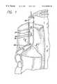
- the venous systemcontains numerous one-way valves for directing blood flow back to the heart such as those valves 20 located in the vein 22 shown in FIG. 1 .
- the arrow leading out the top of the veinrepresents the antegrade flow of blood back to the heart.
- Venous valvesare usually bicuspid valves, with each cusp 24 forming a sack or reservoir 26 for blood which, under retrograde blood pressure, forces the free surfaces of the cusps together to prevent retrograde flow of the blood and allows only antegrade blood flow to the heart.
- Competent venous valvesprevent retrograde flow as blood is pushed forward through the vein lumen and back to the heart.
- FIG. 2A cross-sectional perspective view of a dilated vein with an incompetent valve 28 taken along lines 2 — 2 of FIG. 1 is illustrated in FIG. 2 .
- valve cusps 24can experience some separation at the commissure due to the thinning and stretching of the vein wall at the cusps.
- Two venous conditions which often result from valve failureare varicose veins and more symptomatic chronic venous insufficiency.
- the varicose vein conditionincludes dilation and tortuosity of the superficial veins of the lower limbs, resulting in unsightly discoloration, pain, swelling, and possibly ulceration.
- Varicose veinsoften involve incompetence of one or more venous valves, which allow reflux of blood within the superficial system. This can also worsen deep venous reflux and perforator reflux.
- Current treatments of vein insufficiencyinclude surgical procedures such as vein stripping, ligation, and occasionally, vein-segment transplant.
- Chronic venous insufficiencyinvolves an aggravated condition of varicose veins which may be caused by degenerative weakness in the vein valve segment, or by hydrodynamic forces acting on the tissues of the body, such as the legs, ankles, and feet.
- the hydrostatic pressureincreases on the next venous valves down, causing those veins to dilate.
- more venous valveswill eventually fail.
- the effective height of the column of blood above the feet and anklesgrows, and the weight and hydrostatic pressure exerted on the tissues of the ankle and foot increases.
- ulcerations of the anklebegin to form, which start deep and eventually come to the surface. These ulcerations do not heal easily because of poor venous circulation due to valvular incompetence in the deep venous system and other vein systems.
- Other related venous conditionsinclude dilated hemorrhoids and esophageal varices. Pressure and dilation of the hemorrhoid venous plexus may cause internal hemorrhoids to dilate and/or prolapse and be forced through the anal opening. If a hemorrhoid remains prolapsed, considerable discomfort, including itching and bleeding, may result. The venous return from these prolapsed hemorrhoids becomes obstructed by the anal sphincters, which gives rise to a strangulated hemorrhoid. Thromboses result where the blood within the prolapsed vein becomes clotted. This extremely painful condition can cause edema and inflammation.
- Varicose veins called esophageal varicescan form in the venous system with submucosa of the lower esophagus, and bleeding can occur from the dilated veins. Bleeding or hemorrhaging may result from esophageal varices, which can be difficult to stop and, if untreated, could develop into a life threatening condition. Such varices erode easily, and lead to a massive gastrointestinal hemorrhage.
- Ligation of a fallopian tubefor sterilization or other purposes is typically performed by laparoscopy.
- a doctorsevers the fallopian tube or tubes and ties the ends.
- External cauterization or clampsmay also be used.
- General or regional anestheticmust be used. All of the above are performed from outside the fallopian tube.
- ligationor “intra-luminal ligation” comprises the occlusion, collapse, or closure of a lumen or hollow anatomical structure by the application of energy from within the lumen or structure.
- ligationor “intra-luminal ligation” includes electro-ligation. In the case of fallopian tube ligation, it would be desirable to perform the ligation from within the fallopian tube itself (intra-fallopian tube) to avoid the trauma associated with external methods.
- Ligationinvolves the cauterization or coagulation of a lumen using energy, such as that applied through an electrode device.
- An electrode deviceis introduced into the lumen and positioned so that it contacts the lumen wall. Once properly positioned, RF energy is applied to the wall by the electrode device thereby causing the wall to shrink in cross-sectional diameter.
- a reduction in cross-sectional diameter of the veinas for example from 5 mm (0.2 in) to 1 mm (0.04 in), significantly reduces the flow of blood through a lumen and results in an effective occlusion.
- the vein wallmay completely collapse thereby resulting in a full-lumen obstruction that blocks the flow of blood through the vein.
- a fallopian tubemay collapse sufficiently to effect a sterilization of the patient.
- One apparatus for performing ligationincludes a tubular shaft having an electrode device attached at the distal tip.
- the leadsterminate at an electrical connector, while at the distal end of the shaft the leads are connected to the electrode device.
- the electrical connectorprovides the interface between the leads and a power source, typically an RF generator.
- the RF generatoroperates under the guidance of a control device, usually a microprocessor.
- the ligation apparatusmay be operated in either a monopolar or bipolar configuration.
- the electrode deviceconsists of an electrode that is either positively or negatively charged.
- a return path for the current passing through the electrodeis provided externally from the body, as for example by placing the patient in physical contact with a large low-impedance pad. The current flows between the ligation device and low impedance pad through the patient.
- the electrode deviceIn a bipolar configuration, the electrode device consists of a pair of electrodes having different potentials (such as a pair of oppositely-charged electrodes) of approximately equal size, separated from each other, such as by a dielectric material or by a spatial relationship. Accordingly, in the bipolar mode, the return path for current is provided by an electrode or electrodes of the electrode device itself. The current flows from one electrode, through the tissue, and returns by way of the another electrode.
- a temperature sensing deviceis typically attached to the electrode device, although it may be located elsewhere.
- the temperature sensing devicemay be a thermocouple that monitors the temperature of the venous tissue.
- the thermocoupleinterfaces with the RF generator and the controller through the shaft and provides electrical signals to the controller which monitors the temperature and adjusts the energy applied to the tissue through the electrode device accordingly.
- a fixed-size electrode devicetypically contacts the vein wall at only one point or a limited arc on the circumference or inner diameter of the vein wall.
- RF energyis highly concentrated within the contacting venous tissue, while the flow of RF current through the remainder of the venous tissue is disproportionately weak. Accordingly, the regions of the vein wall near the area of contact collapse at a faster rate than other regions of the vein wall, resulting in non-uniform shrinkage of the vein lumen.
- the overall strength of the occlusionmay be inadequate and the lumen may eventually reopen.
- RF energymust be applied for an extended period of time so that the current flows through the tissue, including through the tissue not in contact with the electrode, generating thermal energy and causing the tissue to shrink sufficiently.
- Extended applications of energyhave a greater possibility of increasing the temperature of the blood to an unacceptable level and may result in a significant amount of heat-induced coagulum forming on the electrode and in the vein which is not desirable.
- exsanguinationcomprises the removal of all or some significant portion of blood in a particular area.
- the effectiveness of a ligating apparatus having a fixed-size electrode deviceis limited to certain sized veins.
- An attempt to ligate a vein having a diameter that is substantially greater than the fixed-size electrode devicecan result in not only non-uniform heating of the vein wall as just described, but also insufficient shrinkage of the vein diameter.
- the greater the diameter of the vein relative to the diameter of the electrode devicethe weaker the energy applied to the vein wall at points distant from the point of electrode contact.
- larger diameter veinsmust shrink a larger percentage for effective occlusion to occur. Accordingly, the vein wall is likely to not completely collapse prior to the venous tissue becoming over-cauterized at the point of electrode contact.
- a technique of reducing the diameter of the lumen of a vein at least close to the final desired diameter before applying energy to the veinhas been found to aid in the efficiency of these types of procedures.
- the pre-reduction in vein diameterassists in pre-shaping the vein to be molded into a ligated state.
- the compressionalso exsanguinates the vein and forces blood away from the treatment site, thus preventing coagulation.
- One valuable technique employedis that of compressing the vein contained within a limb by applying external hydraulic pressure, via a pressure tourniquet, to the limb.
- a pressure tourniquetUnfortunately there are some areas of the body to which a pressure tourniquet cannot be applied, such as the sapheno-femoral junction, which is above the thigh proximate the groin area.
- there are sites where a pressure tourniquet may be ineffectivesuch as: the popliteal junction and other areas around the knee; and the ankle area (typically the posterior arch vein and some of the lower cockett perforators).
- tumescent anesthesiathere exists a technique referred to as tumescent anesthesia that has been used in connection with liposuction procedures.
- the word “tumescent”means swollen or firm. This technique is accomplished by subcutaneously delivering into target fatty tissue a large volume of saline solution containing diluted Lidocaine and Epinephrine (adrenaline), a vasoconstrictive drug. The injected area then becomes locally anesthetized, and the adrenaline temporarily constricts the capillaries and other blood vessels. The tumescence-inducing fluid, or “tumescent fluid” is injected under pressure which causes the target fatty tissue to become swollen and firm.
- the tumescent fluidis typically pumped into the pocket of fat in order to numb the area, loosen the fat, and constrict the blood vessels to minimize bleeding or bruising in a liposuction procedure.
- the anesthetic and other agents in the tumescent solutionshould be allowed sufficient time to diffuse and take full effect throughout the target tissue. After surgery, patients may leave without assistance, and often return to their regular routine within several days. With the tumescent technique, postoperative discomfort is significantly reduced. The local anesthesia often remains in the treated tissue for 16 hours after surgery. Employing a technique of utilizing tumescent anesthesia in conjunction with ligation or radial lumen shrinkage less than ligation may provide benefits.
- the present inventionis directed to a method and apparatus for applying energy to a hollow anatomical structure such as a vein, to shrink the structure.
- the inventionis directed to pre-compressing and exsanguinating a hollow anatomical structure while providing anesthetic and insulation benefits during a procedure of shrinking the hollow anatomical structure.
- a methodcomprises providing fluid to tissue surrounding a hollow anatomical structure to induce tumescence of the tissue and consequent compression of the hollow anatomical structure during a procedure of applying energy to the hollow anatomical structure from within the structure.
- the methodcomprises introducing into the hollow anatomical structure a catheter having a working end and at least one electrode at the working end; placing the electrode into contact with the inner wall of the pre-compressed hollow anatomical structure and applying energy to the hollow anatomical structure at the treatment site via the electrode until the hollow anatomical structure durably assumes dimensions less than or equal to the pre-compressed dimensions caused by the injection of the solution into the tissue.
- tumescent fluidis injected in the tissue surrounding the hollow anatomical structure along a selected length of the hollow anatomical structure.
- the electrodeis then moved along a site within the selected length while continuously applying energy to result in a lengthy occlusion.
- the electrodeis moved down a given length of the hollow anatomical structure and energy is applied at that adjacent site.
- the hollow anatomical structuredurably assumes dimensions less than or equal to the pre-compressed dimensions caused by the injection of the solution into the tissue.
- tumescent anesthesia fluidis injected or otherwise provided to tissue contiguous with a vein to compress the vein to about a desired final diameter.
- a catheter having an energy application device, such as expandable electrodes,is introduced internal to the vein at a site within the compressed portion of the vein and energy is applied to the internal vein wall by the application device. Sufficient energy is applied to cause the vein to durably assume the compressed diameter such that when the effects of the tumescent anesthesia fluid are dissipated, the vein retains the compressed diameter.
- Alternate means to prevent coagulum formationinclude fluid displacement of blood at the treatment site, or exsanguination by inducing self-constriction of the vessel.
- self-constrictionincludes, but is not limited to, intraluminal delivery of a vasoconstrictive drug. Self-constriction also aids in pre-shaping the vein for ligation, as discussed previously. If the fluid delivered to the site is a sclerosant, the ligation effects would be further enhanced.
- energyis applied to effectively occlude the treatment site.
- the energy application deviceis moved along the treatment site while performing the step of applying energy so as to result in a lengthy occlusion of the treatment site.
- the treatment sitemay collapse around the energy application device as it is being moved.
- fluidis delivered from within the hollow structure to the treatment site. This fluid may be used to exsanguinate the treatment site.
- Such fluidmay be from the following group: saline; a vasoconstrictive agent; a sclerosing agent; a high impedance fluid; and heparin.
- temperaturesare sensed at two separate locations on the energy application device, and the temperature signals are averaged to determine the temperature at the site.
- electrical energyis applied to the inner wall of the treatment site with an electrode, the electrode being in apposition with the inner wall. With the electrode being in apposition with the inner wall, the method further comprises the steps of applying electrical energy with the electrode to effectively occlude the treatment site at the electrode, and moving the electrode along the treatment site while maintaining the electrode in apposition with the vein wall while performing the step of applying energy to effectively occlude the treatment site so as to result in a lengthy effective occlusion of the treatment site. Sufficient energy is applied to collapse the hollow anatomical structure around the energy application device as it is being moved along the treatment site to result in a lengthy effective occlusion of the treatment site.
- apposition of the energy application device with the inner wall of the hollow anatomical structureis determined by monitoring the impedance experienced by the energy application device.
- FIG. 1shows a cross-sectional view of a vein having competent valves and having a dilated section with incompetent venous valves in a lower limb which are to be treated in accordance with the present invention
- FIG. 2shows a representative view of a venous section with an incompetent valve from FIG. 1 taken along lines 2 — 2 which is to be treated in accordance with the present invention
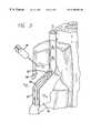
- FIG. 3is a cross-sectional view of the vein of FIG. 1 after the vein has been compressed, although not to full occlusion, by the injection of a tumescent anesthesia fluid in tissue surrounding the vein showing a catheter including an expandable electrode device prior to the application of energy to the vein;
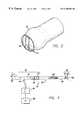
- FIG. 4is a diagram of an energy application system that may be used in conjunction with the method of the present invention, depicting a partial cutaway view of the first embodiment of the catheter showing both the working end and the connecting end with an RF generator and a microprocessor connected at the connection end;
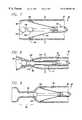
- FIG. 5is a cross-sectional view of the working end of an embodiment of a catheter in accordance with the invention depicting the electrodes in a fully retracted position;
- FIG. 5 ais an end view of the working end of the embodiment of the catheter taken along line 5 a — 5 a of FIG. 5;
- FIG. 6is a cross-sectional view of the working end of the embodiment of the catheter of FIGS. 5 and 5 a depicting the electrodes in a fully expanded position;
- FIG. 6 ais an end view of the working end of the embodiment of the catheter taken along line 6 a — 6 a of FIG. 6;
- FIG. 7is a cross-sectional view of a vein after the vein has been compressed, although not to full occlusion, by tumescent anesthesia fluid, the vein containing the catheter of FIG. 5 with the electrodes in apposition with the vein;
- FIG. 8is a cross-sectional view of the compressed vein containing the catheter of FIG. 5 where the vein is being ligated by the application of energy from the electrodes;
- FIG. 9is a partial cross-sectional view of the vein wall of FIG. 8 showing a lengthy effective occlusion made by moving the electrodes along the treatment site of the vein while maintaining the electrodes in apposition and continuing to apply energy to the vein wall.
- FIG. 10is a side view of an embodiment of an electrode catheter having two pluralities of longitudinally-separated expandable electrodes in a retracted condition
- FIG. 11is a side view of the embodiment of the electrode catheter of FIG. 10 with both pluralities of the electrodes in expanded configurations;
- FIG. 12is a partial cross-sectional view of the embodiment of an electrode catheter of FIGS. 10 and 11 .
- the inventionis directed toward the intravenous treatment of veins using a catheter to deliver at least one electrode to a venous treatment site.
- like reference numeralswill designate similar elements in the various embodiments of the present invention to be discussed.
- the term “working end”will refer to the direction toward the treatment site in the patient, and the term “connecting end” will refer to the direction away from the treatment site in the patient. The invention will be described in relation to the treatment of the venous system of the lower limbs.
- the inventionis not limited thereto and may be employed intraluminally to treat veins in other areas of the body such as hemorrhoids, esophageal varices, and venous-drainage-impotence of the penis.
- the inventionwill be described as using RF energy from the electrode, it is to be understood that other forms of energy such as microwaves, ultrasound, direct current, circulating heated fluid, radiant light, and lasers can be used, and that the thermal energy generated from a resistive coil or curie point element may be used as well.
- one preferred method of the present inventioncan be performed using the catheter 30 to deliver an expandable electrode device 32 (partially shown) to a venous treatment site in order to ligate the vein.
- an expandable electrode device 32partially shown
- a tumescent anesthesia techniquecan be used to inject a dilute anesthetic and vasoconstrictive solution into the tissue surrounding the vein to be treated.
- the tumescent solutionpreferably includes mostly saline solution, with a local anesthetic such as Lidocaine, and a vasoconstrictive drug such as Epinephrine.
- the tumescent solutioncauses the surrounding tissue 34 to become swollen which compresses the vein 22 , as indicated by the arrows, close to occlusion (in this case) or to occlusion. Sufficient tumescent solution should be delivered into the tissue surrounding the vein to compress and exsanguinate the vein.
- the catheter 30is placed within the vein at the treatment site, with the expandable electrode device retracted.
- the solutionis typically infused with a peristaltic pump. However, 60 cc or 100 cc syringes 35 can be used.
- Another alternativeis an IV bag with a pressure cuff. Large volumes are typically delivered into the perivenal area via a large cannula. Sites are typically located 10 cm apart down the leg. Usually there are four or five delivery sites. The external result is a leg that appears inflated. The internal result is compressed veins plus an anesthetized leg.
- the expandable electrode deviceis then expanded into apposition with the venous tissue after compression of the vein. Energy such as high frequency RF energy is applied from the expandable electrode device to the venous tissue until the vein durably assumes dimensions less than or equal to the compressed dimensions caused by the injection of the tumescent solution into the tissue.
- the electrodemay be retracted and the catheter moved to another venous section where the ligation process is repeated. Ultrasound guidance can be used to monitor the progress of the procedure.
- the catheter 30includes an expandable energy application device 56 which in this embodiment, comprises an array of electrodes 58 , an outer sheath 36 having a distal orifice 38 at its working end 40 .
- the connector end 42 of the outer sheathis attached to a handle 44 that includes electrical connector 46 .
- the handleadditionally includes a guide wire port 48 .
- the connector 46is for interfacing with a power source, typically an RF generator 50 , and a microprocessor controller 52 .
- the power source and microprocessor controllerare usually contained in one unit.
- the microprocessor controllercontrols the RF generator in response to external commands and data from a temperature sensor 54 , such as a thermocouple, or temperature sensors that may be positioned at an intraluminal venous treatment site.
- the catheter 30includes the expandable electrode device 56 that moves in and out of the outer sheath by way of the distal orifice 38 in this embodiment, although in other embodiments the device 56 may expand from and contract into the catheter 30 at other locations.
- the expandable electrode device 56includes a plurality of electrodes 58 which can be expanded by moving the outer sheath 36 relative to the electrodes.
- FIG. 4illustrates a plurality of electrodes 58 surrounding a single central electrode, different electrode configurations may be used.
- a fluid port 62communicates with the interior of the outer sheath.
- the catheter 30can be periodically flushed out with saline through the fluid port.
- the flushing fluidcan travel between the outer sheath and the inner sheath.
- the fluid portalso allows for the delivery of drug therapies. Flushing out the catheter prevents the buildup of biological fluid, such as blood, within the catheter.
- the treatment area or site of the veincan be flushed with a fluid such as saline, or a high impedance dielectric fluid, in order to evacuate blood from the treatment area of the vein so as to prevent the formation of coagulum or thrombosis.
- a high impedance dielectric fluidcan minimize unintended heating effects away from the treatment area.
- the dielectric fluiddirects the current of RF energy toward the vein wall.
- a vasoconstrictive agentmay be applied to shrink the vein
- heparinmay be applied for coagulation avoidance
- a sclerosing agentmay be applied to assist in ligation.
- the catheter 30includes a lumen which begins at the distal tip 55 , proximate the working end 40 , and runs substantially along the axis of the inner member before terminating at the guide wire port 48 of the handle 44 .
- a guide wirecan be introduced through the lumen of the catheter for use in guiding the catheter to the desired treatment site.
- the catheteris sized to treat smaller veins, the outer diameter of the catheter may not allow for a fluid flush between the outer sheath and the inner sheath 60 . However, a fluid flush can be introduced through the guide wire port 48 in such an embodiment.
- an actuator 76controls the extension of the electrode device 56 through the distal orifice 38 .
- the actuatormay take the form of a switch, lever 78 , threaded control knob, or other suitable mechanism, and is preferably one that can provide fine control over the movement of the outer sheath 36 or the inner sheath 60 , as the case may be.
- the actuatorinterfaces with the outer sheath to move it back and forth relative to the inner sheath.
- the actuatorinterfaces with the inner sheath to move it back and forth relative to the outer sheath. The relative position between the outer sheath and inner sheath is thus controlled, but other control approaches may be used.
- FIG. 5In a preferred embodiment of a catheter 90 is illustrated in FIG. 5 .
- An inner member 92 or sheathis contained within the outer sheath 94 .
- the inner sheathis preferably constructed from a flexible polymer such as polymide, polyethylene, or nylon, and can travel the entire length of the catheter. The majority of the catheter should be flexible so as to navigate the tortuous paths of the venous system.
- a hypotube having a flared distal end 98 and a circular crosssectional shapeis attached over the distal end of the inner sheath 92 .
- the hypotube 96is preferably no more than about two to three centimeters in length. The hypotube acts as part of a conductive secondary lead 100 .
- An uninsulated conductive electrode sphere 102is slipped over the hypotube.
- the flared distal end of the hypotubeprevents the electrode sphere from moving beyond the distal end of the hypotube.
- the sphereis permanently affixed to the hypotube, such as by soldering the sphere both front and back on the hypotube.
- the majority of the surface of the electrode sphereremains uninsulated.
- the remainder of the hypotubeis preferably insulated so that the sphere-shaped distal end can act as the electrode.
- the hypotubecan be covered with an insulating material such as a coating of parylene.
- the interior lumen of the hypotubeis lined by the inner sheath 92 which is attached to the flared distal end of the hypotube by adhesive such as epoxy.
- the secondary lead 100Surrounding the secondary lead 100 are a plurality of primary leads 104 that preferably have a flat rectangular strip shape and can act as arms.
- the strip shapeis a width from 0.76 mm (0.03 in) to 1.00 mm (0.04 in) and a thickness of approximately 0.13 mm (0.005 in.).
- the plurality of primary leads 104is preferably connected to common conductive rings 106 . This configuration maintains the position of the plurality of primary leads, while reducing the number of internal electrical connections.
- the conductive rings 106are attached to the inner sheath 92 . The position of the rings and the primary leads relative to the outer sheath 94 follows that of the inner sheath.
- the hypotube 96 of the secondary leadis also attached to the inner sheath.
- Two separate conductive ringscan be used so that the polarity of different primary leads can be controlled separately.
- adjacent primary leadscan be connected to one of the two separate conductive rings so that the adjacent leads can be switched to have either opposite polarities or the same polarity.
- the ringsare preferably spaced closely together, but remain electrically isolated from each other along the inner sheath. Both the rings and the hypotube are coupled with the inner sheath, and the primary leads that are connected to the rings move together with the secondary lead while remaining electrically isolated from the secondary lead. Epoxy or another suitable adhesive can be used to attach the rings to the inner sheath.
- FIG. 6 aillustrates an end view of the working end of catheter 90 taken along line 6 a — 6 a of FIG. 6 .
- the conductive rings 106 and the primary leads 104are attached together to act as cantilevers where the ring forms the base and the rectangular primary leads operate as the cantilever arms.
- the primary leadsare formed to have an arc or bend such that the primary leads act as arms that tend to spring outwardly away from the catheter 90 and toward the surrounding venous tissue. Insulation along the underside of the primary leads and the conductive rings prevents unintended electrical coupling therebetween.
- the primary leadsare formed straight and connected to the conductive rings at an angle such that the primary leads tend to expand or spring radially outward from the conductive rings.
- the angle at which the primary leads are attached to the conductive ringsshould be sufficient to force the primary distal ends and their electrodes 108 through blood and into apposition with the vein wall 80 but not enough to preclude vein shrinkage.
- the primary leads 104are formed with enough strength, and are mounted or bent such that they expand outwardly into apposition with the inner wall of the vein.
- the force they develop in an outward directionis not strong enough to prevent radial shrinkage of the vein.
- the shrinking veincauses a contraction of the primary electrodes. Due to the outward force constantly exerted by the primary leads 104 , the electrodes 108 remain in constant apposition with the vein wall as it shrinks.
- the rectangular cross section of the primary leadscan provide increased stability in the lateral direction while allowing the necessary bending in the radial direction.
- the primary leadsare less likely to bend sideways when expanded outward due to the increased size of the rectangular lead in that sideways direction, and a uniform spacing between primary leads is more assured. Uniform spacing between the primary leads and the distal ends promotes uniform heating around the vein by the electrodes 108 .
- the distal ends of the primary leads 104are uninsulated to act as the electrodes 108 having a rounded shape.
- the shapeis convex which may take the form of a spoon or hemispherical shape.
- the primary leadscan be stamped to produce an integral shaped electrode at the distal end of the primary leads.
- the uninsulated outer portion of the distal end of the electrodes 108 which are to come into apposition with the wall of the veinis preferably rounded and convex.
- the flattened or non-convex inner portion of the distal endis insulated to minimize any unintended thermal effect, such as on the surrounding blood in a vein.
- the distal ends of the electrodes 108are configured such that when the distal ends are forced toward the inner sheath 92 , as shown in FIG. 5 a the distal ends combine to form a substantially spherical shape with a profile smaller than the spherical electrode 102 at the secondary distal end.
- the electrodes 108comprise a convex, square center section with semi-circular ends. It has been found that this “race track” configuration maximizes surface area of contact for the electrodes 108 shown.
- the outer sheath 94can slide over and surround the primary and secondary leads 100 and 104 .
- the outer sheathincludes an orifice 110 which is dimensioned to have approximately the same size as the spherical electrode 102 at the secondary distal end. A close or snug fit between the spherical electrode 102 and the orifice 110 of the outer sheath is achieved. This configuration provides an atraumatic tip for the catheter 90 .
- the spherical electrode 102is preferably slightly larger than the orifice 110 .
- the inner diameter of the outer sheathis approximately the same as the diameter of the reduced profile of the combined primary distal end electrodes 108 .
- a fluid portcan communicate with the interior of the outer sheath 94 so that fluid can be flushed between the outer sheath and inner sheath 92 as described above.
- a fluid portcan communicate with a central lumen 112 in the hypotube which can also accept a guide wire for use in guiding the catheter to the desired treatment site.
- another lumencan be formed in the catheter to deliver fluid to the treatment site.
- the delivered fluiddisplaces or exsanguinates blood from the vein so as to avoid heating and coagulation of blood.
- the delivery of a dielectric fluidincreases the surrounding impedance so that RF energy is directed into the tissue of the vein wall.
- An alternate fluidcould be a sclerosing agent which could serve to displace blood or to further enhance occlusion of the vein when applied before, during, or after energy delivery.
- the fluidcan also include an anticoagulant such as heparin which can chemically discourage the coagulation of blood at the treatment site.
- the catheter 90can be periodically flushed with saline which can prevent the buildup of biological fluid, such as blood, within the catheter.
- the salinecan be flushed through the central lumen 112 or between the inner and outer sheaths. If a central lumen is not desired, the lumen of the hypotube can be filled with solder.
- the electrode device 114can operate in either a bipolar or a monopolar configuration. When adjacent primary leads have opposite polarity, a bipolar electrode operation is available. When the primary leads are commonly charged a monopolar electrode operation is available in combination with a large return electrode pad placed in contact with the patient. When the primary electrodes 108 are commonly charged or have a first potential, and a secondary electrode 102 has an opposite polarity or different potential, a bipolar electrode operation is available. More or fewer leads may be used. The number of leads can be dependent on the size or diameter of the vein to be treated, as described above.
- the catheter 90can include one or more temperature sensors, such as thermocouples, mounted in place on an electrode 108 so that the sensor is substantially flush with the exposed surface of the electrode 108 .
- the temperature sensorsenses the temperature of the portion of the vein that is in apposition with the exposed electrode 108 surface.
- the sensorprovides an indication of when shrinkage occurs (70 degrees C. or higher).
- Application of RF energy from the electrodes 108is halted or reduced when the monitored temperature reaches or exceeds the specific temperature that was selected by the operator, such as the temperature at which venous tissue begins to cauterize.
- the catheterin the operation of this embodiment of a catheter 90 , the catheter is inserted into a vein 22 .
- Fluoroscopy, ultrasound, an angioscope imaging technique, or another techniquemay be used to direct and confirm the specific placement of the catheter in the vein.
- Impedance measurementscan also be used to determine proper positioning of the catheter, particularly at the ostium of a vessel such as at the sapheno-femoral junction. The impedance will be low when the electrodes are in the blood stream.
- the cathetercan then be moved until a high impedance value is obtained, indicating electrode contact with the vein wall.
- the vein wall 80has been compressed by the introduction of tumescent anesthesia into the tissue surrounding the vein as indicated by the arrows.
- the arrows in the figuresindicate the compression of the tissue. Unless stated otherwise, all drawing figures having arrows indicating tissue compression are not drawn to scale for purposes of clarity of illustration and are meant to be representations of the vein in a nearly fully occluded state.
- the reduction in the vein 22 diameter caused by the tumescence of the issue in contact with the treatment siteassists in pre-shaping the vein to be molded to a ligated state.
- the compressionalso exsanguinates the vein and forces blood away from the treatment site, thus preventing coagulation.
- the actuator 76(FIG. 4) is then operated to retract the outer sheath 94 to expose leads the 100 and 104 .
- the primary leads 104move outward relative to the axis defined by the outer sheath, while the secondary lead 100 remains substantially linear along the axis defined by the outer sheath.
- the primary leadscontinue to move outward until their electrodes 108 are placed in apposition with the vein wall 80 and the outward movement of the primary leads is impeded.
- the primary electrodes 108contact the vein wall along a generally circumferential area or band of the vein wall. This outward movement of the primary leads occurs in a substantially symmetrical fashion so that the primary electrodes 108 are substantially evenly spaced.
- the electrodes 86can be spaced apart in a staggered fashion such that they do not lie in the same plane.
- the adjacent electrodes 86can extend different lengths from the catheter so that a smaller cross-sectional profile is achieved when the electrodes 86 are collapsed toward one another.
- the RF generator 50is activated to provide suitable RF energy.
- suitable frequencyis 510 kHz.
- One criterion used in selecting the frequency of the energy to be appliedis the control desired over the spread, including the depth, of the thermal effect in the venous tissue. Another criterion is compatibility with filter circuits for eliminating RF noise from thermocouple signals.
- the primary electrodes 108are charged with one polarity opposite that of the secondary electrode 102 . The coupling between oppositely charged primary and secondary electrodes produces RF fields therebetween, and form a symmetrical RF field pattern along a circumferential band of the vein wall 80 to achieve a uniform temperature distribution along the vein wall being treated.
- the RF energyproduces a thermal effect which causes the venous tissue to shrink, reducing the diameter of the vein 22 .
- the thermal effectproduces structural transfiguration of the collagen fibrils in the vein.
- the collagen fibrilsshorten and thicken in cross-section in response to the heat from the thermal effect.
- the energycauses the vein wall 88 to collapse until further collapse is impeded by the primary lead electrodes 108 .
- the primary lead electrodesare pressed closer together by the shrinking vein wall and assume a reduced profile shape which is sufficiently small so that the vein is effectively ligated.
- the catheter 90is pulled back while continuing energy delivery as shown in FIG. 9 .
- Ligation as the catheter is being retractedproduces a lengthy occlusion 89 which is stronger and less susceptible to recanalization than an acute point occlusion.
- the secondary-lead electrode 102In a monopolar operation, the secondary-lead electrode 102 remains neutral, while the primary electrodes 108 are commonly charged and act in conjunction with an independent electrical device, such as a large low-impedance return pad (not shown) placed in external contact with the body, to form RF fields substantially evenly spaced around the circumference of the vein.
- an independent electrical devicesuch as a large low-impedance return pad (not shown) placed in external contact with the body, to form RF fields substantially evenly spaced around the circumference of the vein.
- the thermal effect produced by those RF fields along the axial length of the vein wall 80causes the vein wall to collapse around the primary lead electrodes.
- the electrode deviceis retracted as described in the bipolar operation.
- the application of RF energyis substantially symmetrically distributed through the vein wall, as previously described.
- the electrodesshould be spaced no more than 4 or 5 millimeters apart along the circumference of the vein wall 80 , which defines the target vein diameter for a designed electrode catheter. Where the electrodes are substantially evenly spaced in a substantially symmetrical arrangement, and the spacing between the electrodes is maintained, a symmetrical distribution of RF energy increases the predictability and uniformity of the shrinkage and the strength of the occlusion.
- the primary leadsmay be mounted or otherwise configured such that they expand outwardly in an asymmetrical fashion.
- One purpose for an asymmetrical electrode arrangementis to only shrink a portion of the vein wall to achieve occlusion. Such may be desired in the case of preferentially shrinking a tributary branch or aneurysm on one side of the vein.
- the actuator 76causes the primary leads 104 to return to the interior of the outer sheath 94 . Once the primary leads are within the outer sheath, the catheter 90 may be moved to another venous section where the ligation process is repeated.
- an expandable electrode catheter 118includes two sets of expandable electrode leads 120 and 122 , although additional sets of electrode leads may be possible.
- the electrodes 124 of this embodimentare similar to the electrodes of the embodiment illustrated in FIG. 6 having electrodes with a rounded, convex, spoon-shaped contact area. Other shapes for the electrode may be used, such as ellipses, rounded, ovals, race tracks, and others. Although only one electrode is indicated by numeral 124 in FIGS. 10 and 11, this is for purposes of clarity in the drawings only. All electrodes are meant to be indicated by numeral 124 . While each set of electrode leads may include as few as two electrode leads, the illustrated embodiment includes six electrode leads per set, although more than six electrode leads may be used as well.
- the sets of electrode leads 120 and 122are longitudinally separated from each other.
- the electrodes within each set of electrode leadsare separated from one another radially and each of those electrodes is also separated from every electrode in the other set longitudinally, due to the longitudinal separation. There therefore exists radial separation and longitudinal separation of electrodes at the working end 126 of the catheter 118 in the arrangement shown in FIGS. 10 and 11.
- Electrodes leads presented in FIGS. 10 and 11greater flexibility exists in establishing current flows through the tissue of a patient. As in previous embodiments, the electrodes expand outwardly into contact with patient tissue. Where all the electrodes of a first set of electrode leads have the same polarity, there may be an odd number of electrodes in the set, or an even number. All electrodes in the set may be connected to a common connection point, such as the conducting ring 106 shown in FIG. 6. A single conductor from the connecting end of the catheter may power all electrodes of the set by a single connection to that conducting ring. All electrodes of a second set of electrode leads may also be commonly connected at a respective conducting ring but to a different electrical potential than the first set.
- a monopolar arrangementmay also be established if desired by setting all electrodes of all electrode leads to the same electrical potential and establishing a different electrical potential outside the patient, such as at a “backplate” in contact with the skin of the patient at a selected location. Energy from the working end 126 of the catheter will then flow through the patient to the return provided by the backplate.
- the electrodes in the first set of electrode leadsmay be individually controlled so that there are electrode pairs of differing potentials in the set of leads. This would establish a bipolar approach within the first set of leads itself. If the electrodes of the second set of leads are likewise connected for different potentials among themselves, they too would provide a bipolar approach in their own set and currents would flow through patient tissue between the electrodes in each set of leads.
- Electrodes having a first polarity in the first setare aligned with the electrodes having a different polarity in the second set of leads, energy would not only flow between the bipolar electrodes within the set but would also flow to the electrodes in the other set resulting in two bipolar arrangements at the single working end of the catheter.
- Patient tissue of a length at least as great as the distance between the first and second sets of electrode leadswill receive energy as well as patient tissue between electrodes within each set of leads itself.
- a further arrangement coupled with the bipolar approach just describedwould be to also use a backplate at a different electrical potential to provide further control over the energy flow through the patient's tissue.
- energywould flow between the electrodes within each set of leads, between electrodes in different sets of leads, and between electrodes and the backplate.
- each of the electrodesmay be individually connected to a power source ( 50 , FIG. 4) and the electrical potential at each electrode can be individually controlled.
- This arrangementmay yield even more precise control over the current densities through patient tissue.
- the potential between the electrodes of the same setmay be reduced but the potential between those electrodes and the electrodes of the second set of leads may be increased resulting in the desired current flow densities.
- the electrodesmay be controlled so that energy flows between such electrodes and the backplate. Because each electrode is individually controlled, the level of energy it imparts to the tissue at its location is controllable.
- One factor that could affect the number of electrodes per set of electrode leadsis the diameter of the vein being treated.
- the design of the contact pad for the electrode leadscould also affect the desired number of electrodes for a given procedure.
- the electrode leads 120 , 122are formed to expand outwardly into apposition with the target tissue, yet as the target tissue shrinks, the electrodes maintain contact with that tissue and are moved inwardly by that tissue. Because of this arrangement, the leads compensate for variations in the diameter of the vein. They are therefore capable of maintaining apposition with the tissue whether or not compression of the vein or anatomical structure exists, such as by use of a pressure cuff or tourniquet or tumescence of the surrounding tissue.
- the tip 128 of the electrode catheter 118should have a hemispherical or another atraumatic shape.
- the tip 128may be electrically neutral, and may be fabricated from a polymer or it may be fabricated of stainless steel. Because the tip 128 has a rounded shape and is located at the distal extreme of the catheter, it may perform a guiding function when introducing the catheter to the patient.
- the double set of expandable electrodescan be used to ligate veins or other hollow anatomical structures in a manner similar to that previously described.
- the outer sheath 130can be pulled back to allow the electrode to expand outwardly from the catheter and into apposition with the wall of the lumen being treated.
- the two sets of electrodes 120 and 122apply energy to the lumen to cause it to shrink to a reduced diameter.
- the cathetercan be moved or pulled back while the energy is being applied to treat an extended area of the lumen.
- the desired area of the lumen or veinis treated (e.g., ligated) energy is no longer provided to the electrodes, and the outer sheath 130 is pushed forward to force the expanded electrodes back to an unexpanded condition.
- the cathetercan then be removed from the patient, or another section of the vein can be treated.
- FIG. 12there is shown a partial cross-section view of the catheter of FIGS. 10 and 11.
- Two pluralities of electrodes 120 and 122are shown with the electrodes of the first plurality 120 being indicated by numeral 124 and the electrodes of the second plurality 122 being indicated by numeral 150 .
- Each electrodeis formed from an electrically-conductive electrode lead 152 and 154 respectively that is electrically insulated along its length except at its distal end at which point no insulation exists thus forming the electrode.
- Each leadhas an outward bend (not shown).
- An inner tube 156includes a lumen 158 through which fluid may flow for flush or other purposes, or through which a guide wire may be positioned.
- a hypotube 160is positioned over the inner tube and layers of insulation 162 are mounted over the hypotube.
- the first plurality 120 of electrode leads 152extend proximally to a first mounting ring 164 to which all are connected.
- the second plurality 122 of electrode leads 154extend proximally to a second mounting ring 166 to which all are connected.
- the rings 164 and 166are mounted over the hypotube insulation so that no electrical conduction path exists between the two.
- Wire conductors 168 and 170extend from the proximal end of the catheter to each ring so that all electrode leads connected to a particular ring are interconnected electrically.
- alternating electrodes of a particular pluralityare connected to two different rings.
- Each ringis separately connected to the power source and the polarities of the rings may therefore be made different to establish a bipolar approach within the plurality.
- One electrodemay be a “+” polarity while the two adjacent electrodes may be a “ ⁇ ” polarity. In this case then, there would be a total of three rings for all electrodes.
- both pluralitieswould have two rings for its respective electrodes with alternating electrodes connected to different rings so that bipolar approaches within each plurality may be established. In this case, there would exist a total of four rings for the two pluralities of electrodes.
- An outer movable sheath 172when slid in the distal direction to the point shown in FIG. 12 will cause the electrode leads to contract to the position shown.
- the sheath 172acts as a deployment device in that it will move past the bend (not shown) in each of the electrode leads of the second plurality 122 permitting all electrode leads to expand outwardly as shown in FIG. 11 .
- the electrode leadsare formed of stainless steel in this embodiment and with the thin insulation layer and the outward bend, have enough strength to automatically move outwardly through blood flow (in a venous application) and into apposition with the inner wall of the target tissue.
- the inner wallshrinks due to the application of heat by the electrodes, the inner wall will force the electrode leads toward their contracted position but the electrodes will automatically stay in apposition with the inner wall during the entire ligation process due to their outward bends and the material of which they are formed.
- the electrode 124includes a temperature sensor 54 and an electrode of the second plurality also includes a temperature sensor 54 . Although not shown as such, they are mounted flush with the outer electrode surfaces and their wires protrude inwardly through the electrode and are held in place along the respective leads 152 and 154 .
- the microprocessor 52receives the signals from both temperature sensors, averages those signals and determines the effective temperature at the treatment site based on that average signal. Methods of averaging temperature signals are well known to those skilled in the art and no further description is provided here.
- Electrodes and leadshave been described as protruding from a distal orifice in the catheter, they may be expanded by other means and in other configurations. In another embodiments, the leads may be deployed by an inner pull wire, hydraulics, or magnetic fields.
- the benefits of tumescencewould include locally anesthetizing the treatment area for a prolonged period of time and insulating most of the surrounding tissue and nerves from the damage of heat conducting from the treated vein.
- An additional benefit of the vasoconstriction induced by the Epinephrinewould be that the constricted blood vessels would limit how fast the body absorbed the Lidocaine thus keeping the level of Lidocaine absorbed below the toxicity level.
- extended applications of energyhave a greater possibility of increasing the temperature of the blood to an unacceptable level and may result in a significant amount of heat-induced coagulum forming on the electrode and in the vein which is not desirable.
- Using a tumescent anesthesia compression techniqueincluding the administration of vasocontrictive drugs, would aid in preventing this problem by exsanguinating the vein.
Landscapes
- Physics & Mathematics (AREA)
- Health & Medical Sciences (AREA)
- Life Sciences & Earth Sciences (AREA)
- Surgery (AREA)
- Engineering & Computer Science (AREA)
- Nonlinear Science (AREA)
- Nuclear Medicine, Radiotherapy & Molecular Imaging (AREA)
- Geometry (AREA)
- General Physics & Mathematics (AREA)
- Cardiology (AREA)
- Crystallography & Structural Chemistry (AREA)
- Plasma & Fusion (AREA)
- Chemical & Material Sciences (AREA)
- Otolaryngology (AREA)
- Mathematical Physics (AREA)
- Optics & Photonics (AREA)
- Biomedical Technology (AREA)
- Heart & Thoracic Surgery (AREA)
- Medical Informatics (AREA)
- Molecular Biology (AREA)
- Animal Behavior & Ethology (AREA)
- General Health & Medical Sciences (AREA)
- Public Health (AREA)
- Veterinary Medicine (AREA)
- Surgical Instruments (AREA)
Abstract
Description
Claims (39)
Priority Applications (7)
| Application Number | Priority Date | Filing Date | Title |
|---|---|---|---|
| US09/267,127US6258084B1 (en) | 1997-09-11 | 1999-03-10 | Method for applying energy to biological tissue including the use of tumescent tissue compression |
| US09/841,664US6969388B2 (en) | 1997-09-11 | 2001-04-23 | Apparatus for applying energy to biological tissue including the use of tumescent tissue compression |
| US09/899,885US6752803B2 (en) | 1997-09-11 | 2001-07-06 | Method and apparatus for applying energy to biological tissue including the use of tumescent tissue compression |
| US10/872,646US7396355B2 (en) | 1997-09-11 | 2004-06-21 | Method and apparatus for applying energy to biological tissue including the use of tumescent tissue compression |
| US11/841,983US20080039829A1 (en) | 1997-09-11 | 2007-08-20 | Method and apparatus for applying energy to biological tissue including the use of tumescent tissue compression |
| US11/841,913US20080039793A1 (en) | 1997-09-11 | 2007-08-20 | Method and apparatus for applying energy to biological tissue including the use of tumescent tissue compression |
| US12/140,219US20080249519A1 (en) | 1997-09-11 | 2008-06-16 | Method and apparatus for applying energy to biological tissue including the use of tumescent tissue compression |
Applications Claiming Priority (3)
| Application Number | Priority Date | Filing Date | Title |
|---|---|---|---|
| US08/927,251US6200312B1 (en) | 1997-09-11 | 1997-09-11 | Expandable vein ligator catheter having multiple electrode leads |
| US09/138,472US6179832B1 (en) | 1997-09-11 | 1998-08-21 | Expandable catheter having two sets of electrodes |
| US09/267,127US6258084B1 (en) | 1997-09-11 | 1999-03-10 | Method for applying energy to biological tissue including the use of tumescent tissue compression |
Related Parent Applications (2)
| Application Number | Title | Priority Date | Filing Date |
|---|---|---|---|
| US08/927,251Continuation-In-PartUS6200312B1 (en) | 1997-09-11 | 1997-09-11 | Expandable vein ligator catheter having multiple electrode leads |
| US09/138,472Continuation-In-PartUS6179832B1 (en) | 1997-09-11 | 1998-08-21 | Expandable catheter having two sets of electrodes |
Related Child Applications (3)
| Application Number | Title | Priority Date | Filing Date |
|---|---|---|---|
| US09/841,664DivisionUS6969388B2 (en) | 1997-09-11 | 2001-04-23 | Apparatus for applying energy to biological tissue including the use of tumescent tissue compression |
| US09/899,885ContinuationUS6752803B2 (en) | 1997-09-11 | 2001-07-06 | Method and apparatus for applying energy to biological tissue including the use of tumescent tissue compression |
| US09/899,855ContinuationUS20020008799A1 (en) | 1997-09-11 | 2001-07-09 | Liquid crystal display unit |
Publications (1)
| Publication Number | Publication Date |
|---|---|
| US6258084B1true US6258084B1 (en) | 2001-07-10 |
Family
ID=27385186
Family Applications (6)
| Application Number | Title | Priority Date | Filing Date |
|---|---|---|---|
| US09/267,127Expired - LifetimeUS6258084B1 (en) | 1997-09-11 | 1999-03-10 | Method for applying energy to biological tissue including the use of tumescent tissue compression |
| US09/841,664Expired - Fee RelatedUS6969388B2 (en) | 1997-09-11 | 2001-04-23 | Apparatus for applying energy to biological tissue including the use of tumescent tissue compression |
| US09/899,885Expired - LifetimeUS6752803B2 (en) | 1997-09-11 | 2001-07-06 | Method and apparatus for applying energy to biological tissue including the use of tumescent tissue compression |
| US10/872,646Expired - Fee RelatedUS7396355B2 (en) | 1997-09-11 | 2004-06-21 | Method and apparatus for applying energy to biological tissue including the use of tumescent tissue compression |
| US11/841,913AbandonedUS20080039793A1 (en) | 1997-09-11 | 2007-08-20 | Method and apparatus for applying energy to biological tissue including the use of tumescent tissue compression |
| US11/841,983AbandonedUS20080039829A1 (en) | 1997-09-11 | 2007-08-20 | Method and apparatus for applying energy to biological tissue including the use of tumescent tissue compression |
Family Applications After (5)
| Application Number | Title | Priority Date | Filing Date |
|---|---|---|---|
| US09/841,664Expired - Fee RelatedUS6969388B2 (en) | 1997-09-11 | 2001-04-23 | Apparatus for applying energy to biological tissue including the use of tumescent tissue compression |
| US09/899,885Expired - LifetimeUS6752803B2 (en) | 1997-09-11 | 2001-07-06 | Method and apparatus for applying energy to biological tissue including the use of tumescent tissue compression |
| US10/872,646Expired - Fee RelatedUS7396355B2 (en) | 1997-09-11 | 2004-06-21 | Method and apparatus for applying energy to biological tissue including the use of tumescent tissue compression |
| US11/841,913AbandonedUS20080039793A1 (en) | 1997-09-11 | 2007-08-20 | Method and apparatus for applying energy to biological tissue including the use of tumescent tissue compression |
| US11/841,983AbandonedUS20080039829A1 (en) | 1997-09-11 | 2007-08-20 | Method and apparatus for applying energy to biological tissue including the use of tumescent tissue compression |
Country Status (1)
| Country | Link |
|---|---|
| US (6) | US6258084B1 (en) |
Cited By (69)
| Publication number | Priority date | Publication date | Assignee | Title |
|---|---|---|---|---|
| US20010041888A1 (en)* | 1997-09-11 | 2001-11-15 | Goldman Mitchel P. | Method and apparatus for applying energy to biological tissue including the use of tumescent tissue compression |
| US6712815B2 (en) | 2001-01-16 | 2004-03-30 | Novacept, Inc. | Apparatus and method for treating venous reflux |
| US20040092913A1 (en)* | 2002-10-31 | 2004-05-13 | Hennings David R. | Endovenous closure of varicose veins with mid infrared laser |
| US20050203497A1 (en)* | 2004-03-12 | 2005-09-15 | Trevor Speeg | Medical apparatus and method useful for positioning energy delivery device |
| US20050203496A1 (en)* | 2004-03-12 | 2005-09-15 | Ritchie Paul G. | Medical apparatus and method useful for thermal treatment of a lumen |
| US20050288655A1 (en)* | 2004-06-29 | 2005-12-29 | Howard Root | Laser fiber for endovenous therapy having a shielded distal tip |
| US20060009802A1 (en)* | 2004-07-10 | 2006-01-12 | Modesitt D B | Biological tissue closure device and method |
| US20060030849A1 (en)* | 2004-08-05 | 2006-02-09 | Vnus Medical Technologies, Inc. | Methods and apparatus for coagulating and/or constricting hollow anatomical structures |
| WO2006017754A1 (en)* | 2004-08-05 | 2006-02-16 | Vnus Medical Technologies, Inc. | Methods and apparatus for coagulating and/or constricting hollow anatomical structures |
| US20060052822A1 (en)* | 2004-08-31 | 2006-03-09 | Mirizzi Michael S | Apparatus and material composition for permanent occlusion of a hollow anatomical structure |
| US20060069417A1 (en)* | 1996-03-05 | 2006-03-30 | Vnus Medical Technologies, Inc. | Method for treating venous insufficiency using directionally applied energy |
| US20060106338A1 (en)* | 2004-11-18 | 2006-05-18 | Chang David W | Endoluminal delivery of anesthesia |
| US20060190076A1 (en)* | 2003-11-17 | 2006-08-24 | Taheri Syde A | Temporary absorbable venous occlusive stent and superficial vein treatment method |
| US20060189979A1 (en)* | 2005-02-23 | 2006-08-24 | Esch Brady D | Methods and apparatus for coagulating and/or constricting hollow anatomical structures |
| US20060271078A1 (en)* | 2005-05-12 | 2006-11-30 | Modesitt D B | Access and closure device and method |
| US20070027454A1 (en)* | 2004-05-12 | 2007-02-01 | Modesitt D B | Access and closure device and method |
| WO2007014063A2 (en) | 2005-07-21 | 2007-02-01 | Vnus Medical Technologies, Inc. | Systems and methods for treating a hollow anatomical structure |
| US20070088346A1 (en)* | 2005-10-14 | 2007-04-19 | Mirizzi Michael S | Method and apparatus for varicose vein treatment using acoustic hemostasis |
| US20070123846A1 (en)* | 2002-10-31 | 2007-05-31 | Cooltouch Incorporated | Preparation for endovenous laser ablation |
| US20070179486A1 (en)* | 2004-06-29 | 2007-08-02 | Jeff Welch | Laser fiber for endovenous therapy having a shielded distal tip |
| US20080021527A1 (en)* | 2003-10-30 | 2008-01-24 | Cooltouch Incorporated | Endovenous laser treatment generating reduced blood coagulation |
| US20080017043A1 (en)* | 2006-06-01 | 2008-01-24 | The Coca-Cola Company | Tea Stick Brewing Package and Method |
| US20090005775A1 (en)* | 1997-09-11 | 2009-01-01 | Vnus Medical Technologies, Inc. | Expandable catheter having two sets of electrodes |
| US7524316B2 (en) | 2002-10-31 | 2009-04-28 | Cooltouch, Inc. | Endovenous closure of varicose veins with mid infrared laser |
| US20090171272A1 (en)* | 2007-12-29 | 2009-07-02 | Tegg Troy T | Deflectable sheath and catheter assembly |
| US20090264875A1 (en)* | 2002-07-10 | 2009-10-22 | Appling William M | Method of Treating a Blood Vessel with an Optical Fiber Having a Spacer |
| US20090299443A1 (en)* | 2008-05-30 | 2009-12-03 | Boston Scientific Scimed, Inc. | Guide catheter having vasomodulating electrodes |
| US20090306640A1 (en)* | 2008-06-06 | 2009-12-10 | Grant Michael Glaze | Vein Therapy Device and Method |
| US7674260B2 (en) | 2005-04-28 | 2010-03-09 | Cytyc Corporation | Emergency hemostasis device utilizing energy |
| US7731712B2 (en) | 2004-12-20 | 2010-06-08 | Cytyc Corporation | Method and system for transcervical tubal occlusion |
| US20100198209A1 (en)* | 2009-01-30 | 2010-08-05 | Tartaglia Joseph M | Hemorrhoid Therapy and Method |
| US20100217250A1 (en)* | 2009-02-24 | 2010-08-26 | Sierra Surgical Technologies | Methods and systems for controlled thermal tissue |
| US7815661B2 (en) | 2005-01-25 | 2010-10-19 | Tyco Healthcare Group, Lp | Method and apparatus for implanting an occlusive structure |
| US20100305632A1 (en)* | 2009-05-26 | 2010-12-02 | Barun Maskara | Temperature assisted stimulation |
| US7846160B2 (en) | 2006-12-21 | 2010-12-07 | Cytyc Corporation | Method and apparatus for sterilization |
| US7955369B2 (en) | 2004-09-27 | 2011-06-07 | Tyco Healthcare Group Lp | Systems and methods for treating a hollow anatomical structure |
| US20110166518A1 (en)* | 2010-01-04 | 2011-07-07 | Tyco Healthcare Group, L.P. | Apparatus and methods for treating hollow anatomical structures |
| US8048086B2 (en) | 2004-02-25 | 2011-11-01 | Femasys Inc. | Methods and devices for conduit occlusion |
| US8048101B2 (en) | 2004-02-25 | 2011-11-01 | Femasys Inc. | Methods and devices for conduit occlusion |
| US8052669B2 (en) | 2004-02-25 | 2011-11-08 | Femasys Inc. | Methods and devices for delivery of compositions to conduits |
| US8291915B2 (en) | 1997-03-04 | 2012-10-23 | Tyco Healthcare Group Lp | Method and apparatus for treating venous insufficiency using directionally applied energy |
| US8409183B2 (en) | 2003-10-30 | 2013-04-02 | Cooltouch Incorporated | Endovenous laser treatment generating reduced blood coagulation |
| US8448644B2 (en) | 2006-11-02 | 2013-05-28 | Cooltouch Incorporated | Sonic endovenous catheter |
| US8465451B2 (en) | 2005-06-22 | 2013-06-18 | Covidien Lp | Methods and apparatus for introducing tumescent fluid to body tissue |
| US8486060B2 (en) | 2006-09-18 | 2013-07-16 | Cytyc Corporation | Power ramping during RF ablation |
| US8506563B2 (en) | 1996-04-12 | 2013-08-13 | Cytyc Surgical Products | Moisture transport system for contact electrocoagulation |
| US8551082B2 (en) | 1998-05-08 | 2013-10-08 | Cytyc Surgical Products | Radio-frequency generator for powering an ablation device |
| EP2662041A2 (en) | 2005-07-21 | 2013-11-13 | Covidien LP | Systems and methods for treating a hollow anatomical structure |
| US8696620B2 (en) | 2010-07-30 | 2014-04-15 | St. Jude Medical, Atrial Fibrillation Division, Inc. | Catheter with a mechanism for omni-directional deflection of a catheter shaft |
| US8979882B2 (en) | 2008-07-21 | 2015-03-17 | Arstasis, Inc. | Devices, methods, and kits for forming tracts in tissue |
| US8998897B2 (en) | 2011-08-19 | 2015-04-07 | Cook Medical Technologies Llc | Ablation cap |
| US9017361B2 (en) | 2006-04-20 | 2015-04-28 | Covidien Lp | Occlusive implant and methods for hollow anatomical structure |
| EP2923663A1 (en)* | 2014-03-24 | 2015-09-30 | Terumo Kabushiki Kaisha | Treatment device |
| US9238127B2 (en) | 2004-02-25 | 2016-01-19 | Femasys Inc. | Methods and devices for delivering to conduit |
| US9526570B2 (en) | 2012-10-04 | 2016-12-27 | Cook Medical Technologies Llc | Tissue cutting cap |
| US9554826B2 (en) | 2008-10-03 | 2017-01-31 | Femasys, Inc. | Contrast agent injection system for sonographic imaging |
| US9782562B2 (en) | 2002-04-04 | 2017-10-10 | Angiodynamics, Inc. | Venous insufficiency treatment method |
| US9814513B2 (en) | 2011-06-30 | 2017-11-14 | Angiodynamics, Inc. | Endovascular plasma treatment device and method of use |
| US10070888B2 (en) | 2008-10-03 | 2018-09-11 | Femasys, Inc. | Methods and devices for sonographic imaging |
| US10238453B2 (en) | 2002-07-10 | 2019-03-26 | Angiodynamics, Inc. | Method of making an endovascular laser treatment device for causing closure of a blood vessel |
| US10357305B2 (en) | 2014-03-26 | 2019-07-23 | Venclose, Inc. | Venous disease treatment |
| US10441753B2 (en) | 2012-05-25 | 2019-10-15 | Arstasis, Inc. | Vascular access configuration |
| US10675447B2 (en) | 2012-05-25 | 2020-06-09 | Arstasis, Inc. | Vascular access configuration |
| US11576724B2 (en) | 2011-02-24 | 2023-02-14 | Eximo Medical Ltd. | Hybrid catheter for vascular intervention |
| US11684420B2 (en) | 2016-05-05 | 2023-06-27 | Eximo Medical Ltd. | Apparatus and methods for resecting and/or ablating an undesired tissue |
| US11918182B2 (en) | 2011-08-19 | 2024-03-05 | Cook Medical Technologies Llc | Cap for attachment to an endoscope |
| US12038322B2 (en) | 2022-06-21 | 2024-07-16 | Eximo Medical Ltd. | Devices and methods for testing ablation systems |
| US12171463B2 (en) | 2008-10-03 | 2024-12-24 | Femasys Inc. | Contrast agent generation and injection system for sonographic imaging |
| US12376904B1 (en) | 2020-09-08 | 2025-08-05 | Angiodynamics, Inc. | Dynamic laser stabilization and calibration system |
Families Citing this family (231)
| Publication number | Priority date | Publication date | Assignee | Title |
|---|---|---|---|---|
| US7789876B2 (en)* | 2000-08-14 | 2010-09-07 | Tyco Healthcare Group, Lp | Method and apparatus for positioning a catheter relative to an anatomical junction |
| US20020071474A1 (en)* | 2000-11-10 | 2002-06-13 | Werneth Randell L. | Device for measuring temperature of vessel walls |
| US7617005B2 (en) | 2002-04-08 | 2009-11-10 | Ardian, Inc. | Methods and apparatus for thermally-induced renal neuromodulation |
| US8175711B2 (en) | 2002-04-08 | 2012-05-08 | Ardian, Inc. | Methods for treating a condition or disease associated with cardio-renal function |
| US9308043B2 (en) | 2002-04-08 | 2016-04-12 | Medtronic Ardian Luxembourg S.A.R.L. | Methods for monopolar renal neuromodulation |
| US7756583B2 (en) | 2002-04-08 | 2010-07-13 | Ardian, Inc. | Methods and apparatus for intravascularly-induced neuromodulation |
| US7620451B2 (en) | 2005-12-29 | 2009-11-17 | Ardian, Inc. | Methods and apparatus for pulsed electric field neuromodulation via an intra-to-extravascular approach |
| US6978174B2 (en) | 2002-04-08 | 2005-12-20 | Ardian, Inc. | Methods and devices for renal nerve blocking |
| US20070129761A1 (en) | 2002-04-08 | 2007-06-07 | Ardian, Inc. | Methods for treating heart arrhythmia |
| US7853333B2 (en) | 2002-04-08 | 2010-12-14 | Ardian, Inc. | Methods and apparatus for multi-vessel renal neuromodulation |
| US20080213331A1 (en) | 2002-04-08 | 2008-09-04 | Ardian, Inc. | Methods and devices for renal nerve blocking |
| US8145316B2 (en) | 2002-04-08 | 2012-03-27 | Ardian, Inc. | Methods and apparatus for renal neuromodulation |
| US9308044B2 (en) | 2002-04-08 | 2016-04-12 | Medtronic Ardian Luxembourg S.A.R.L. | Methods for therapeutic renal neuromodulation |
| US7162303B2 (en) | 2002-04-08 | 2007-01-09 | Ardian, Inc. | Renal nerve stimulation method and apparatus for treatment of patients |
| US8774922B2 (en) | 2002-04-08 | 2014-07-08 | Medtronic Ardian Luxembourg S.A.R.L. | Catheter apparatuses having expandable balloons for renal neuromodulation and associated systems and methods |
| US8774913B2 (en) | 2002-04-08 | 2014-07-08 | Medtronic Ardian Luxembourg S.A.R.L. | Methods and apparatus for intravasculary-induced neuromodulation |
| US9636174B2 (en) | 2002-04-08 | 2017-05-02 | Medtronic Ardian Luxembourg S.A.R.L. | Methods for therapeutic renal neuromodulation |
| US8347891B2 (en) | 2002-04-08 | 2013-01-08 | Medtronic Ardian Luxembourg S.A.R.L. | Methods and apparatus for performing a non-continuous circumferential treatment of a body lumen |
| US8145317B2 (en) | 2002-04-08 | 2012-03-27 | Ardian, Inc. | Methods for renal neuromodulation |
| US20140018880A1 (en) | 2002-04-08 | 2014-01-16 | Medtronic Ardian Luxembourg S.A.R.L. | Methods for monopolar renal neuromodulation |
| US7653438B2 (en) | 2002-04-08 | 2010-01-26 | Ardian, Inc. | Methods and apparatus for renal neuromodulation |
| US8150519B2 (en) | 2002-04-08 | 2012-04-03 | Ardian, Inc. | Methods and apparatus for bilateral renal neuromodulation |
| US8131371B2 (en) | 2002-04-08 | 2012-03-06 | Ardian, Inc. | Methods and apparatus for monopolar renal neuromodulation |
| US20070135875A1 (en) | 2002-04-08 | 2007-06-14 | Ardian, Inc. | Methods and apparatus for thermally-induced renal neuromodulation |
| US6752767B2 (en) | 2002-04-16 | 2004-06-22 | Vivant Medical, Inc. | Localization element with energized tip |
| US7181288B1 (en)* | 2002-06-24 | 2007-02-20 | The Cleveland Clinic Foundation | Neuromodulation device and method of using the same |
| US20040082859A1 (en) | 2002-07-01 | 2004-04-29 | Alan Schaer | Method and apparatus employing ultrasound energy to treat body sphincters |
| DE10254668A1 (en)* | 2002-11-22 | 2004-06-09 | Großpointner, Martina | Device for the treatment of vascular defects |
| US7223266B2 (en)* | 2003-02-04 | 2007-05-29 | Cardiodex Ltd. | Methods and apparatus for hemostasis following arterial catheterization |
| DE202004021953U1 (en) | 2003-09-12 | 2013-06-19 | Vessix Vascular, Inc. | Selectable eccentric remodeling and / or ablation of atherosclerotic material |
| US7722605B2 (en)* | 2004-01-27 | 2010-05-25 | Japan Lifeline Co., Ltd. | Ablation catheter |
| US7346382B2 (en) | 2004-07-07 | 2008-03-18 | The Cleveland Clinic Foundation | Brain stimulation models, systems, devices, and methods |
| US9713730B2 (en) | 2004-09-10 | 2017-07-25 | Boston Scientific Scimed, Inc. | Apparatus and method for treatment of in-stent restenosis |
| US8396548B2 (en) | 2008-11-14 | 2013-03-12 | Vessix Vascular, Inc. | Selective drug delivery in a lumen |
| US20060106350A1 (en)* | 2004-09-13 | 2006-05-18 | Spitz Gregory A | Apparatus and methods for treating undesired veins |
| EP1814478A4 (en)* | 2004-11-22 | 2011-05-18 | Cardiodex Ltd | Techniques for heat-treating varicose veins |
| JP5219518B2 (en) | 2004-12-09 | 2013-06-26 | ザ ファウンドリー, エルエルシー | Aortic valve repair |
| US7842076B2 (en)* | 2004-12-20 | 2010-11-30 | Tyco Healthcare Group, Lp | Systems and methods for treating a hollow anatomical structure |
| CA2598239C (en) | 2005-02-18 | 2019-10-29 | Abraxis Bioscience, Inc. | Nanoparticulate formulations of taxanes and carrier proteins for use in combination chemotherapy |
| ITFI20050028A1 (en)* | 2005-02-21 | 2006-08-22 | El En Spa | DEVICE, CATHETER AND METHOD FOR THE CURATIVE TREATMENT OF VARICOSE VEINS |
| US20060247615A1 (en)* | 2005-04-28 | 2006-11-02 | Boston Scientific Scimed, Inc. | Multi-element bi-polar ablation electrode |
| US8696662B2 (en) | 2005-05-12 | 2014-04-15 | Aesculap Ag | Electrocautery method and apparatus |
| US7803156B2 (en) | 2006-03-08 | 2010-09-28 | Aragon Surgical, Inc. | Method and apparatus for surgical electrocautery |
| US8728072B2 (en) | 2005-05-12 | 2014-05-20 | Aesculap Ag | Electrocautery method and apparatus |
| US9339323B2 (en) | 2005-05-12 | 2016-05-17 | Aesculap Ag | Electrocautery method and apparatus |
| US7942874B2 (en) | 2005-05-12 | 2011-05-17 | Aragon Surgical, Inc. | Apparatus for tissue cauterization |
| US8303505B2 (en) | 2005-12-02 | 2012-11-06 | Abbott Cardiovascular Systems Inc. | Methods and apparatuses for image guided medical procedures |
| WO2007084508A2 (en)* | 2006-01-13 | 2007-07-26 | Mirabilis Medica, Inc. | Apparatus for delivering high intensity focused ultrasound energy to a treatment site internal to a patient's body |
| US8277379B2 (en)* | 2006-01-13 | 2012-10-02 | Mirabilis Medica Inc. | Methods and apparatus for the treatment of menometrorrhagia, endometrial pathology, and cervical neoplasia using high intensity focused ultrasound energy |
| US20070244371A1 (en)* | 2006-04-04 | 2007-10-18 | Nguyen Hoa D | Phlebectomy illumination device and methods |
| US8574229B2 (en) | 2006-05-02 | 2013-11-05 | Aesculap Ag | Surgical tool |
| US8019435B2 (en) | 2006-05-02 | 2011-09-13 | Boston Scientific Scimed, Inc. | Control of arterial smooth muscle tone |
| US20070265613A1 (en)* | 2006-05-10 | 2007-11-15 | Edelstein Peter Seth | Method and apparatus for sealing tissue |
| EP2076198A4 (en) | 2006-10-18 | 2009-12-09 | Minnow Medical Inc | Inducing desirable temperature effects on body tissue |
| JP5559539B2 (en) | 2006-10-18 | 2014-07-23 | べシックス・バスキュラー・インコーポレイテッド | System that induces desirable temperature effects on body tissue |
| EP2455036B1 (en) | 2006-10-18 | 2015-07-15 | Vessix Vascular, Inc. | Tuned RF energy and electrical tissue characterization for selective treatment of target tissues |
| JP2008132163A (en)* | 2006-11-28 | 2008-06-12 | Olympus Medical Systems Corp | Body lumen obstruction treatment instrument |
| US8435235B2 (en) | 2007-04-27 | 2013-05-07 | Covidien Lp | Systems and methods for treating hollow anatomical structures |
| ITTO20080032U1 (en)* | 2007-05-11 | 2008-09-12 | Ceramoptec Gmbh | SYSTEM AND METHOD FOR HEMORROID TREATMENT |
| US8052604B2 (en)* | 2007-07-31 | 2011-11-08 | Mirabilis Medica Inc. | Methods and apparatus for engagement and coupling of an intracavitory imaging and high intensity focused ultrasound probe |
| EP2182875A4 (en)* | 2007-08-15 | 2011-08-24 | Cardiodex Ltd | Systems and methods for puncture closure |
| US8439907B2 (en)* | 2007-11-07 | 2013-05-14 | Mirabilis Medica Inc. | Hemostatic tissue tunnel generator for inserting treatment apparatus into tissue of a patient |
| US8187270B2 (en)* | 2007-11-07 | 2012-05-29 | Mirabilis Medica Inc. | Hemostatic spark erosion tissue tunnel generator with integral treatment providing variable volumetric necrotization of tissue |
| US8292880B2 (en) | 2007-11-27 | 2012-10-23 | Vivant Medical, Inc. | Targeted cooling of deployable microwave antenna |
| US8870867B2 (en) | 2008-02-06 | 2014-10-28 | Aesculap Ag | Articulable electrosurgical instrument with a stabilizable articulation actuator |
| US9220889B2 (en) | 2008-02-11 | 2015-12-29 | Intelect Medical, Inc. | Directional electrode devices with locating features |
| US8019440B2 (en) | 2008-02-12 | 2011-09-13 | Intelect Medical, Inc. | Directional lead assembly |
| US9272153B2 (en) | 2008-05-15 | 2016-03-01 | Boston Scientific Neuromodulation Corporation | VOA generation system and method using a fiber specific analysis |
| US8059059B2 (en)* | 2008-05-29 | 2011-11-15 | Vivant Medical, Inc. | Slidable choke microwave antenna |
| US9770297B2 (en) | 2008-06-04 | 2017-09-26 | Covidien Lp | Energy devices and methods for treating hollow anatomical structures |
| US9248318B2 (en) | 2008-08-06 | 2016-02-02 | Mirabilis Medica Inc. | Optimization and feedback control of HIFU power deposition through the analysis of detected signal characteristics |
| US8216161B2 (en)* | 2008-08-06 | 2012-07-10 | Mirabilis Medica Inc. | Optimization and feedback control of HIFU power deposition through the frequency analysis of backscattered HIFU signals |
| US9050449B2 (en) | 2008-10-03 | 2015-06-09 | Mirabilis Medica, Inc. | System for treating a volume of tissue with high intensity focused ultrasound |
| EP2331207B1 (en) | 2008-10-03 | 2013-12-11 | Mirabilis Medica Inc. | Apparatus for treating tissues with hifu |
| US9795442B2 (en) | 2008-11-11 | 2017-10-24 | Shifamed Holdings, Llc | Ablation catheters |
| US8295902B2 (en)* | 2008-11-11 | 2012-10-23 | Shifamed Holdings, Llc | Low profile electrode assembly |
| EP2355737B1 (en) | 2008-11-17 | 2021-08-11 | Boston Scientific Scimed, Inc. | Selective accumulation of energy without knowledge of tissue topography |
| US8652129B2 (en) | 2008-12-31 | 2014-02-18 | Medtronic Ardian Luxembourg S.A.R.L. | Apparatus, systems, and methods for achieving intravascular, thermally-induced renal neuromodulation |
| WO2010080886A1 (en) | 2009-01-09 | 2010-07-15 | Recor Medical, Inc. | Methods and apparatus for treatment of mitral valve in insufficiency |
| US20100280328A1 (en)* | 2009-05-01 | 2010-11-04 | Tyco Healthcare Group, Lp | Methods and systems for illumination during phlebectomy procedures |
| US8920369B2 (en) | 2009-06-24 | 2014-12-30 | Shifamed Holdings, Llc | Steerable delivery sheaths |
| AU2010266027B2 (en) | 2009-06-24 | 2015-05-07 | Shifamed Holdings, Llc | Steerable medical delivery devices and methods of use |
| WO2011025865A1 (en) | 2009-08-27 | 2011-03-03 | The Cleveland Clinic Foundation | System and method to estimate region of tissue activation |
| US10973994B2 (en) | 2013-09-16 | 2021-04-13 | Pourang Bral | Means and method to invade skin, mucosa, and underlying tissues with little or no pain |
| US10226586B2 (en) | 2011-05-26 | 2019-03-12 | Pourang Bral | Means and method to painlessly puncture skin |
| US9770560B2 (en) | 2009-11-12 | 2017-09-26 | Pourang Bral | Means and method to administer injections with little or no pain |
| WO2011068997A1 (en) | 2009-12-02 | 2011-06-09 | The Cleveland Clinic Foundation | Reversing cognitive-motor impairments in patients having a neuro-degenerative disease using a computational modeling approach to deep brain stimulation programming |
| ES2436516T3 (en) | 2010-02-04 | 2014-01-02 | Aesculap Ag | Laparoscopic radiofrequency surgical device |
| AU2011232335A1 (en) | 2010-03-24 | 2012-10-11 | Shifamed Holdings, Llc | Intravascular tissue disruption |
| US8827992B2 (en) | 2010-03-26 | 2014-09-09 | Aesculap Ag | Impedance mediated control of power delivery for electrosurgery |
| US8419727B2 (en) | 2010-03-26 | 2013-04-16 | Aesculap Ag | Impedance mediated power delivery for electrosurgery |
| CA3087813A1 (en) | 2010-03-29 | 2011-10-06 | Abraxis Bioscience, Llc | Methods of treating cancer |
| BR112012024590A2 (en) | 2010-03-29 | 2016-05-31 | Abraxis Bioscience Inc | methods of enhancing drug release and efficacy of therapeutic agents |
| WO2011126580A2 (en) | 2010-04-09 | 2011-10-13 | Minnow Medical, Inc. | Power generating and control apparatus for the treatment of tissue |
| US9192790B2 (en) | 2010-04-14 | 2015-11-24 | Boston Scientific Scimed, Inc. | Focused ultrasonic renal denervation |
| US8240313B2 (en)* | 2010-05-10 | 2012-08-14 | Hsu Geng-Long | Physiological approach to penile venous stripping surgical procedure for patients with erectile dysfunction |
| AU2011252976A1 (en) | 2010-05-12 | 2012-11-08 | Shifamed Holdings, Llc | Low profile electrode assembly |
| US9655677B2 (en) | 2010-05-12 | 2017-05-23 | Shifamed Holdings, Llc | Ablation catheters including a balloon and electrodes |
| WO2011153010A1 (en) | 2010-06-04 | 2011-12-08 | Abraxis Biosciences, Llc | Methods of treatment of pancreatic cancer |
| US8473067B2 (en) | 2010-06-11 | 2013-06-25 | Boston Scientific Scimed, Inc. | Renal denervation and stimulation employing wireless vascular energy transfer arrangement |
| US8913804B2 (en) | 2010-06-14 | 2014-12-16 | Boston Scientific Neuromodulation Corporation | Programming interface for spinal cord neuromodulation |
| US9358365B2 (en) | 2010-07-30 | 2016-06-07 | Boston Scientific Scimed, Inc. | Precision electrode movement control for renal nerve ablation |
| US9155589B2 (en) | 2010-07-30 | 2015-10-13 | Boston Scientific Scimed, Inc. | Sequential activation RF electrode set for renal nerve ablation |
| US9084609B2 (en) | 2010-07-30 | 2015-07-21 | Boston Scientific Scime, Inc. | Spiral balloon catheter for renal nerve ablation |
| US9408661B2 (en) | 2010-07-30 | 2016-08-09 | Patrick A. Haverkost | RF electrodes on multiple flexible wires for renal nerve ablation |
| US9463062B2 (en) | 2010-07-30 | 2016-10-11 | Boston Scientific Scimed, Inc. | Cooled conductive balloon RF catheter for renal nerve ablation |
| US9498278B2 (en) | 2010-09-08 | 2016-11-22 | Covidien Lp | Asymmetrical electrodes for bipolar vessel sealing |
| US9173698B2 (en) | 2010-09-17 | 2015-11-03 | Aesculap Ag | Electrosurgical tissue sealing augmented with a seal-enhancing composition |
| US8974451B2 (en) | 2010-10-25 | 2015-03-10 | Boston Scientific Scimed, Inc. | Renal nerve ablation using conductive fluid jet and RF energy |
| TWI513451B (en) | 2010-10-25 | 2015-12-21 | Medtronic Ardian Luxembourg | Devices, systems and methods for evaluation and feedback of neuromodulation treatment |
| US9220558B2 (en) | 2010-10-27 | 2015-12-29 | Boston Scientific Scimed, Inc. | RF renal denervation catheter with multiple independent electrodes |
| US9028485B2 (en) | 2010-11-15 | 2015-05-12 | Boston Scientific Scimed, Inc. | Self-expanding cooling electrode for renal nerve ablation |
| US9089350B2 (en) | 2010-11-16 | 2015-07-28 | Boston Scientific Scimed, Inc. | Renal denervation catheter with RF electrode and integral contrast dye injection arrangement |
| US9668811B2 (en) | 2010-11-16 | 2017-06-06 | Boston Scientific Scimed, Inc. | Minimally invasive access for renal nerve ablation |
| US9326751B2 (en) | 2010-11-17 | 2016-05-03 | Boston Scientific Scimed, Inc. | Catheter guidance of external energy for renal denervation |
| US9060761B2 (en) | 2010-11-18 | 2015-06-23 | Boston Scientific Scime, Inc. | Catheter-focused magnetic field induced renal nerve ablation |
| US9023034B2 (en) | 2010-11-22 | 2015-05-05 | Boston Scientific Scimed, Inc. | Renal ablation electrode with force-activatable conduction apparatus |
| US9192435B2 (en) | 2010-11-22 | 2015-11-24 | Boston Scientific Scimed, Inc. | Renal denervation catheter with cooled RF electrode |
| US20120157993A1 (en) | 2010-12-15 | 2012-06-21 | Jenson Mark L | Bipolar Off-Wall Electrode Device for Renal Nerve Ablation |
| US9220561B2 (en) | 2011-01-19 | 2015-12-29 | Boston Scientific Scimed, Inc. | Guide-compatible large-electrode catheter for renal nerve ablation with reduced arterial injury |
| JP2014518516A (en) | 2011-03-29 | 2014-07-31 | ボストン サイエンティフィック ニューロモデュレイション コーポレイション | System and method for atlas alignment |
| US9227074B2 (en) | 2012-08-28 | 2016-01-05 | Boston Scientific Neuromodulation Corporation | Parameter visualization, selection, and annotation interface |
| US9592389B2 (en) | 2011-05-27 | 2017-03-14 | Boston Scientific Neuromodulation Corporation | Visualization of relevant stimulation leadwire electrodes relative to selected stimulation information |
| US9339327B2 (en) | 2011-06-28 | 2016-05-17 | Aesculap Ag | Electrosurgical tissue dissecting device |
| CN103813745B (en) | 2011-07-20 | 2016-06-29 | 波士顿科学西美德公司 | In order to visualize, be directed at and to melt transcutaneous device and the method for nerve |
| EP2734264B1 (en) | 2011-07-22 | 2018-11-21 | Boston Scientific Scimed, Inc. | Nerve modulation system with a nerve modulation element positionable in a helical guide |
| EP2742450A2 (en) | 2011-08-09 | 2014-06-18 | Boston Scientific Neuromodulation Corporation | Systems and methods for stimulation-related volume analysis, creation, and sharing |
| CN106823131B (en) | 2011-09-30 | 2019-12-20 | 柯惠有限合伙公司 | Energy transfer device and method of use |
| WO2013055826A1 (en) | 2011-10-10 | 2013-04-18 | Boston Scientific Scimed, Inc. | Medical devices including ablation electrodes |
| US9420955B2 (en) | 2011-10-11 | 2016-08-23 | Boston Scientific Scimed, Inc. | Intravascular temperature monitoring system and method |
| EP2765940B1 (en) | 2011-10-11 | 2015-08-26 | Boston Scientific Scimed, Inc. | Off-wall electrode device for nerve modulation |
| US9364284B2 (en) | 2011-10-12 | 2016-06-14 | Boston Scientific Scimed, Inc. | Method of making an off-wall spacer cage |
| EP2768568B1 (en) | 2011-10-18 | 2020-05-06 | Boston Scientific Scimed, Inc. | Integrated crossing balloon catheter |
| US9162046B2 (en) | 2011-10-18 | 2015-10-20 | Boston Scientific Scimed, Inc. | Deflectable medical devices |
| US8951251B2 (en) | 2011-11-08 | 2015-02-10 | Boston Scientific Scimed, Inc. | Ostial renal nerve ablation |
| WO2013074813A1 (en) | 2011-11-15 | 2013-05-23 | Boston Scientific Scimed, Inc. | Device and methods for renal nerve modulation monitoring |
| US9119632B2 (en) | 2011-11-21 | 2015-09-01 | Boston Scientific Scimed, Inc. | Deflectable renal nerve ablation catheter |
| US9265969B2 (en) | 2011-12-21 | 2016-02-23 | Cardiac Pacemakers, Inc. | Methods for modulating cell function |
| US9028472B2 (en) | 2011-12-23 | 2015-05-12 | Vessix Vascular, Inc. | Methods and apparatuses for remodeling tissue of or adjacent to a body passage |
| EP2797534A1 (en) | 2011-12-28 | 2014-11-05 | Boston Scientific Scimed, Inc. | Device and methods for nerve modulation using a novel ablation catheter with polymeric ablative elements |
| US9050106B2 (en) | 2011-12-29 | 2015-06-09 | Boston Scientific Scimed, Inc. | Off-wall electrode device and methods for nerve modulation |
| US9597018B2 (en) | 2012-03-08 | 2017-03-21 | Medtronic Ardian Luxembourg S.A.R.L. | Biomarker sampling in the context of neuromodulation devices, systems, and methods |
| AU2013230781B2 (en) | 2012-03-08 | 2015-12-03 | Medtronic Af Luxembourg S.A.R.L. | Ovarian neuromodulation and associated systems and methods |
| WO2013142217A1 (en)* | 2012-03-19 | 2013-09-26 | Boston Scientific Scimed, Inc. | Expandable electrode device and methods for nerve modulation |
| US8961550B2 (en) | 2012-04-17 | 2015-02-24 | Indian Wells Medical, Inc. | Steerable endoluminal punch |
| US10660703B2 (en) | 2012-05-08 | 2020-05-26 | Boston Scientific Scimed, Inc. | Renal nerve modulation devices |
| US20140031894A1 (en)* | 2012-07-23 | 2014-01-30 | Eugene G. Lipov | Method and device for post-operative application of pulsed radiofrequency for prevention of pain and cartilage loss |
| EP2879757B1 (en) | 2012-08-04 | 2019-06-26 | Boston Scientific Neuromodulation Corporation | Systems and methods for storing and transferring registration, atlas, and lead information between medical devices |
| US10321946B2 (en) | 2012-08-24 | 2019-06-18 | Boston Scientific Scimed, Inc. | Renal nerve modulation devices with weeping RF ablation balloons |
| CN104780859B (en) | 2012-09-17 | 2017-07-25 | 波士顿科学西美德公司 | Self-positioning electrode systems and methods for renal neuromodulation |
| US10398464B2 (en) | 2012-09-21 | 2019-09-03 | Boston Scientific Scimed, Inc. | System for nerve modulation and innocuous thermal gradient nerve block |
| US10549127B2 (en) | 2012-09-21 | 2020-02-04 | Boston Scientific Scimed, Inc. | Self-cooling ultrasound ablation catheter |
| JP6336451B2 (en) | 2012-09-26 | 2018-06-06 | アエスキュラップ アーゲー | Tissue cutting and sealing device |
| CN104869930B (en) | 2012-10-10 | 2020-12-25 | 波士顿科学国际有限公司 | Renal neuromodulation apparatus and methods |
| US20140110296A1 (en) | 2012-10-19 | 2014-04-24 | Medtronic Ardian Luxembourg S.A.R.L. | Packaging for Catheter Treatment Devices and Associated Devices, Systems, and Methods |
| US9792412B2 (en) | 2012-11-01 | 2017-10-17 | Boston Scientific Neuromodulation Corporation | Systems and methods for VOA model generation and use |
| WO2014163987A1 (en) | 2013-03-11 | 2014-10-09 | Boston Scientific Scimed, Inc. | Medical devices for modulating nerves |
| WO2014143571A1 (en) | 2013-03-11 | 2014-09-18 | Boston Scientific Scimed, Inc. | Medical devices for modulating nerves |
| US9808311B2 (en) | 2013-03-13 | 2017-11-07 | Boston Scientific Scimed, Inc. | Deflectable medical devices |
| CN105228546B (en) | 2013-03-15 | 2017-11-14 | 波士顿科学国际有限公司 | Medical devices and methods for treating hypertension utilizing impedance compensation |
| US10265122B2 (en) | 2013-03-15 | 2019-04-23 | Boston Scientific Scimed, Inc. | Nerve ablation devices and related methods of use |
| EP2967734B1 (en) | 2013-03-15 | 2019-05-15 | Boston Scientific Scimed, Inc. | Methods and apparatuses for remodeling tissue of or adjacent to a body passage |
| KR20150140760A (en) | 2013-04-08 | 2015-12-16 | 아파마 메디칼, 인크. | Cardiac ablation catheters and methods of use thereof |
| US10349824B2 (en) | 2013-04-08 | 2019-07-16 | Apama Medical, Inc. | Tissue mapping and visualization systems |
| US10098694B2 (en) | 2013-04-08 | 2018-10-16 | Apama Medical, Inc. | Tissue ablation and monitoring thereof |
| CN105473091B (en) | 2013-06-21 | 2020-01-21 | 波士顿科学国际有限公司 | Renal denervation balloon catheter with co-movable electrode supports |
| CN105473092B (en) | 2013-06-21 | 2019-05-17 | 波士顿科学国际有限公司 | The medical instrument for renal nerve ablation with rotatable shaft |
| US9707036B2 (en) | 2013-06-25 | 2017-07-18 | Boston Scientific Scimed, Inc. | Devices and methods for nerve modulation using localized indifferent electrodes |
| CN105358084B (en) | 2013-07-01 | 2018-11-09 | 波士顿科学国际有限公司 | Medical instrument for renal nerve ablation |
| CN105377169B (en) | 2013-07-11 | 2019-04-19 | 波士顿科学国际有限公司 | Devices and methods for neuromodulation |
| US10413357B2 (en) | 2013-07-11 | 2019-09-17 | Boston Scientific Scimed, Inc. | Medical device with stretchable electrode assemblies |
| US9925001B2 (en) | 2013-07-19 | 2018-03-27 | Boston Scientific Scimed, Inc. | Spiral bipolar electrode renal denervation balloon |
| US10695124B2 (en) | 2013-07-22 | 2020-06-30 | Boston Scientific Scimed, Inc. | Renal nerve ablation catheter having twist balloon |
| US10342609B2 (en) | 2013-07-22 | 2019-07-09 | Boston Scientific Scimed, Inc. | Medical devices for renal nerve ablation |
| CN105473093B (en) | 2013-08-22 | 2019-02-05 | 波士顿科学国际有限公司 | Flexible circuit with improved adhesion to renal neuromodulation balloon |
| US9895194B2 (en) | 2013-09-04 | 2018-02-20 | Boston Scientific Scimed, Inc. | Radio frequency (RF) balloon catheter having flushing and cooling capability |
| EP3043733A1 (en) | 2013-09-13 | 2016-07-20 | Boston Scientific Scimed, Inc. | Ablation balloon with vapor deposited cover layer |
| US11246654B2 (en) | 2013-10-14 | 2022-02-15 | Boston Scientific Scimed, Inc. | Flexible renal nerve ablation devices and related methods of use and manufacture |
| EP3057488B1 (en) | 2013-10-14 | 2018-05-16 | Boston Scientific Scimed, Inc. | High resolution cardiac mapping electrode array catheter |
| US9962223B2 (en) | 2013-10-15 | 2018-05-08 | Boston Scientific Scimed, Inc. | Medical device balloon |
| US9770606B2 (en) | 2013-10-15 | 2017-09-26 | Boston Scientific Scimed, Inc. | Ultrasound ablation catheter with cooling infusion and centering basket |
| EP3057521B1 (en) | 2013-10-18 | 2020-03-25 | Boston Scientific Scimed, Inc. | Balloon catheters with flexible conducting wires |
| CN105658163B (en) | 2013-10-25 | 2020-08-18 | 波士顿科学国际有限公司 | Embedded thermocouple in denervation flexible circuit |
| US9370653B2 (en)* | 2013-12-05 | 2016-06-21 | Advanced Neuromodulation Systems, Inc. | Medical leads with segmented electrodes and methods of fabrication thereof |
| EP3091922B1 (en) | 2014-01-06 | 2018-10-17 | Boston Scientific Scimed, Inc. | Tear resistant flex circuit assembly |
| US11000679B2 (en) | 2014-02-04 | 2021-05-11 | Boston Scientific Scimed, Inc. | Balloon protection and rewrapping devices and related methods of use |
| CN106572881B (en) | 2014-02-04 | 2019-07-26 | 波士顿科学国际有限公司 | Alternative placement of thermal sensors on bipolar electrodes |
| US20150250522A1 (en)* | 2014-03-10 | 2015-09-10 | Terumo Kabushiki Kaisha | Method for treating varicose veins and intraluminal device used in such method |
| US20150250523A1 (en)* | 2014-03-10 | 2015-09-10 | Terumo Kabushiki Kaisha | Method for treating varicose veins and intraluminal device used in such method |
| US20150250536A1 (en)* | 2014-03-10 | 2015-09-10 | Terumo Kabushiki Kaisha | Method for treating varicose veins and intraluminal device used in such method |
| US9579149B2 (en) | 2014-03-13 | 2017-02-28 | Medtronic Ardian Luxembourg S.A.R.L. | Low profile catheter assemblies and associated systems and methods |
| JP2015181705A (en) | 2014-03-24 | 2015-10-22 | テルモ株式会社 | treatment device |
| US10194979B1 (en) | 2014-03-28 | 2019-02-05 | Medtronic Ardian Luxembourg S.A.R.L. | Methods for catheter-based renal neuromodulation |
| US10194980B1 (en) | 2014-03-28 | 2019-02-05 | Medtronic Ardian Luxembourg S.A.R.L. | Methods for catheter-based renal neuromodulation |
| US9980766B1 (en) | 2014-03-28 | 2018-05-29 | Medtronic Ardian Luxembourg S.A.R.L. | Methods and systems for renal neuromodulation |
| GB2525029B (en) | 2014-04-10 | 2016-02-24 | Cook Medical Technologies Llc | Apparatus and method for occluding a vessel by RF embolization |
| US9959388B2 (en) | 2014-07-24 | 2018-05-01 | Boston Scientific Neuromodulation Corporation | Systems, devices, and methods for providing electrical stimulation therapy feedback |
| US10265528B2 (en) | 2014-07-30 | 2019-04-23 | Boston Scientific Neuromodulation Corporation | Systems and methods for electrical stimulation-related patient population volume analysis and use |
| US10272247B2 (en) | 2014-07-30 | 2019-04-30 | Boston Scientific Neuromodulation Corporation | Systems and methods for stimulation-related volume analysis, creation, and sharing with integrated surgical planning and stimulation programming |
| US20160030719A1 (en) | 2014-07-31 | 2016-02-04 | Terumo Kabushiki Kaisha | Method for treating varicose veins and intraluminal device used in such method |
| US20160030023A1 (en)* | 2014-07-31 | 2016-02-04 | Terumo Kabushiki Kaisha | Method for treating varicose veins and intraluminal device used in such method |
| US9974959B2 (en) | 2014-10-07 | 2018-05-22 | Boston Scientific Neuromodulation Corporation | Systems, devices, and methods for electrical stimulation using feedback to adjust stimulation parameters |
| GB201511595D0 (en)* | 2014-12-23 | 2015-08-19 | Whiteley Mark | Medical device for treating a vein |
| US10420537B2 (en) | 2015-03-27 | 2019-09-24 | Shifamed Holdings, Llc | Steerable medical devices, systems, and methods of use |
| JP6820864B2 (en) | 2015-04-24 | 2021-01-27 | カリラ メディカル インコーポレイテッド | Manipulable medical devices, systems and usage |
| CN107530542B (en) | 2015-05-26 | 2020-10-13 | 波士顿科学神经调制公司 | System for analyzing electrical stimulation and selecting or manipulating activation volume |
| US10780283B2 (en) | 2015-05-26 | 2020-09-22 | Boston Scientific Neuromodulation Corporation | Systems and methods for analyzing electrical stimulation and selecting or manipulating volumes of activation |
| ES2940303T3 (en) | 2015-06-29 | 2023-05-05 | Boston Scient Neuromodulation Corp | Stimulation parameter selection systems by use of targets and direction |
| EP3280490B1 (en) | 2015-06-29 | 2021-09-01 | Boston Scientific Neuromodulation Corporation | Systems for selecting stimulation parameters based on stimulation target region, effects, or side effects |
| WO2017062378A1 (en) | 2015-10-09 | 2017-04-13 | Boston Scientific Neuromodulation Corporation | System and methods for clinical effects mapping for directional stimulations leads |
| CN108366715A (en) | 2015-11-09 | 2018-08-03 | 施菲姆德控股有限责任公司 | Steering assembly and application method for medical treatment device |
| EP4302713A3 (en) | 2015-11-16 | 2024-03-13 | Boston Scientific Scimed, Inc. | Energy delivery devices |
| US10716942B2 (en) | 2016-04-25 | 2020-07-21 | Boston Scientific Neuromodulation Corporation | System and methods for directional steering of electrical stimulation |
| EP3458152B1 (en) | 2016-06-24 | 2021-04-21 | Boston Scientific Neuromodulation Corporation | Systems and methods for visual analytics of clinical effects |
| WO2018044881A1 (en) | 2016-09-02 | 2018-03-08 | Boston Scientific Neuromodulation Corporation | Systems and methods for visualizing and directing stimulation of neural elements |
| US10780282B2 (en) | 2016-09-20 | 2020-09-22 | Boston Scientific Neuromodulation Corporation | Systems and methods for steering electrical stimulation of patient tissue and determining stimulation parameters |
| ES2869184T3 (en) | 2016-10-14 | 2021-10-25 | Boston Scient Neuromodulation Corp | Systems to determine in closed loop the configuration of the stimulation parameters of an electrical stimulation system |
| JP6834005B2 (en) | 2017-01-03 | 2021-02-24 | ボストン サイエンティフィック ニューロモデュレイション コーポレイション | Systems and methods for selecting MRI-matched stimulus parameters |
| EP3519043B1 (en) | 2017-01-10 | 2020-08-12 | Boston Scientific Neuromodulation Corporation | Systems and methods for creating stimulation programs based on user-defined areas or volumes |
| US11497507B2 (en) | 2017-02-19 | 2022-11-15 | Orpheus Ventures, Llc | Systems and methods for closing portions of body tissue |
| US10625082B2 (en) | 2017-03-15 | 2020-04-21 | Boston Scientific Neuromodulation Corporation | Visualization of deep brain stimulation efficacy |
| US11357986B2 (en) | 2017-04-03 | 2022-06-14 | Boston Scientific Neuromodulation Corporation | Systems and methods for estimating a volume of activation using a compressed database of threshold values |
| JP6932835B2 (en) | 2017-07-14 | 2021-09-08 | ボストン サイエンティフィック ニューロモデュレイション コーポレイション | Systems and methods for estimating the clinical effects of electrical stimulation |
| EP3634569A1 (en) | 2017-08-15 | 2020-04-15 | Boston Scientific Neuromodulation Corporation | Systems and methods for controlling electrical stimulation using multiple stimulation fields |
| CN111655153B (en) | 2017-12-08 | 2023-10-13 | 泰拉克利昂公司 | Ultrasonic device |
| US11298553B2 (en) | 2018-04-27 | 2022-04-12 | Boston Scientific Neuromodulation Corporation | Multi-mode electrical stimulation systems and methods of making and using |
| EP3784332B1 (en) | 2018-04-27 | 2023-04-26 | Boston Scientific Neuromodulation Corporation | Systems for visualizing and programming electrical stimulation |
| US20210015550A1 (en)* | 2019-07-17 | 2021-01-21 | Biosense Webster (Israel) Ltd. | Catheter for endovascular sympathetic denervation of spasmed intracranial arteries |
| CN111012481B (en)* | 2019-12-31 | 2023-12-01 | 杭州堃博生物科技有限公司 | Radio frequency ablation catheter and radio frequency ablation system |
| US12403315B2 (en) | 2021-04-27 | 2025-09-02 | Boston Scientific Neuromodulation Corporation | Systems and methods for automated programming of electrical stimulation |
| US12403313B2 (en) | 2021-06-15 | 2025-09-02 | Boston Scientific Neuromodulation Corporation | Methods and systems for estimating neural activation by stimulation using a stimulation system |
Citations (12)
| Publication number | Priority date | Publication date | Assignee | Title |
|---|---|---|---|---|
| US373339A (en) | 1887-11-15 | Isidobe eskell cliffoed | ||
| US3301258A (en) | 1963-10-03 | 1967-01-31 | Medtronic Inc | Method and apparatus for treating varicose veins |
| US5437664A (en)* | 1994-01-18 | 1995-08-01 | Endovascular, Inc. | Apparatus and method for venous ligation |
| US5709224A (en) | 1995-06-07 | 1998-01-20 | Radiotherapeutics Corporation | Method and device for permanent vessel occlusion |
| US5810804A (en) | 1995-08-15 | 1998-09-22 | Rita Medical Systems | Multiple antenna ablation apparatus and method with cooling element |
| US5817092A (en) | 1995-11-09 | 1998-10-06 | Radio Therapeutics Corporation | Apparatus, system and method for delivering radio frequency energy to a treatment site |
| US5827268A (en) | 1996-10-30 | 1998-10-27 | Hearten Medical, Inc. | Device for the treatment of patent ductus arteriosus and method of using the device |
| WO1998055072A2 (en) | 1997-06-02 | 1998-12-10 | Vnus Medical Technologies, Inc. | Pressure tourniquet with ultrasound window |
| US5863290A (en) | 1995-08-15 | 1999-01-26 | Rita Medical Systems | Multiple antenna ablation apparatus and method |
| US5868740A (en) | 1995-03-24 | 1999-02-09 | Board Of Regents-Univ Of Nebraska | Method for volumetric tissue ablation |
| GB2333964A (en) | 1999-03-04 | 1999-08-11 | Falah Hasan Ali | Intravenous coagulation catheter for treatment of varicose veins |
| US6036687A (en)* | 1996-03-05 | 2000-03-14 | Vnus Medical Technologies, Inc. | Method and apparatus for treating venous insufficiency |
Family Cites Families (85)
| Publication number | Priority date | Publication date | Assignee | Title |
|---|---|---|---|---|
| US659409A (en) | 1900-08-25 | 1900-10-09 | Charles L Mosher | Electric bipolar dilator. |
| US833759A (en) | 1905-07-27 | 1906-10-23 | John D Sourwine | Surgical instrument. |
| US985865A (en) | 1910-06-29 | 1911-03-07 | William H Turner Jr | Embalming instrument. |
| DE1163993B (en) | 1960-03-23 | 1964-02-27 | Philips Patentverwaltung | Decimeter wave stem radiator for medical treatment |
| US3552382A (en) | 1968-01-11 | 1971-01-05 | Hoffmann La Roche | Ultrasonic transducer assembly for biological inspections |
| US3557794A (en) | 1968-07-30 | 1971-01-26 | Us Air Force | Arterial dilation device |
| US4043338A (en) | 1973-04-30 | 1977-08-23 | Ortho Pharmaceutical Corporation | Pharmaceutical formulation applicator device |
| DE2324658B2 (en) | 1973-05-16 | 1977-06-30 | Richard Wolf Gmbh, 7134 Knittlingen | PROBE FOR COAGULATING BODY TISSUE |
| US4016886A (en) | 1974-11-26 | 1977-04-12 | The United States Of America As Represented By The United States Energy Research And Development Administration | Method for localizing heating in tumor tissue |
| US4119102A (en) | 1975-07-11 | 1978-10-10 | Leveen Harry H | Radio frequency treatment of tumors while inducing hypotension |
| FR2421628A1 (en) | 1977-04-08 | 1979-11-02 | Cgr Mev | LOCALIZED HEATING DEVICE USING VERY HIGH FREQUENCY ELECTROMAGNETIC WAVES, FOR MEDICAL APPLICATIONS |
| US4154246A (en) | 1977-07-25 | 1979-05-15 | Leveen Harry H | Field intensification in radio frequency thermotherapy |
| US4346715A (en) | 1978-07-12 | 1982-08-31 | The United States Of America As Represented By The Administrator Of The National Aeronautics And Space Administration | Hyperthermia heating apparatus |
| US4522205A (en) | 1980-09-03 | 1985-06-11 | The University Court Of The University Of Edinburgh | Therapeutic device and method of inducing thrombosis in a blood vessel |
| US4564011A (en) | 1982-03-22 | 1986-01-14 | Leon Goldman | Laser optic device and method |
| US5370675A (en) | 1992-08-12 | 1994-12-06 | Vidamed, Inc. | Medical probe device and method |
| GB2170144B (en) | 1985-01-24 | 1988-12-21 | Simon Barron Ltd | A system for producing fuel pellets |
| EP0189329A3 (en) | 1985-01-25 | 1987-06-03 | Robert E. Fischell | A tunneling catheter system for transluminal arterial angioplasty |
| DE3516830A1 (en) | 1985-05-10 | 1986-11-13 | Max Dr. 8520 Erlangen Hubmann | CATHETER |
| US4660571A (en) | 1985-07-18 | 1987-04-28 | Cordis Corporation | Percutaneous lead having radially adjustable electrode |
| US4699147A (en) | 1985-09-25 | 1987-10-13 | Cordis Corporation | Intraventricular multielectrode cardial mapping probe and method for using same |
| AT385894B (en) | 1985-10-04 | 1988-05-25 | Basem Dr Nashef | TUBULAR PROBE |
| US4643186A (en) | 1985-10-30 | 1987-02-17 | Rca Corporation | Percutaneous transluminal microwave catheter angioplasty |
| US4664120A (en) | 1986-01-22 | 1987-05-12 | Cordis Corporation | Adjustable isodiametric atrial-ventricular pervenous lead |
| IL78755A0 (en) | 1986-05-12 | 1986-08-31 | Biodan Medical Systems Ltd | Applicator for insertion into a body opening for medical purposes |
| US4709698A (en) | 1986-05-14 | 1987-12-01 | Thomas J. Fogarty | Heatable dilation catheter |
| US5231995A (en) | 1986-11-14 | 1993-08-03 | Desai Jawahar M | Method for catheter mapping and ablation |
| US5215103A (en) | 1986-11-14 | 1993-06-01 | Desai Jawahar M | Catheter for mapping and ablation and method therefor |
| US4765331A (en) | 1987-02-10 | 1988-08-23 | Circon Corporation | Electrosurgical device with treatment arc of less than 360 degrees |
| US4807620A (en) | 1987-05-22 | 1989-02-28 | Advanced Interventional Systems, Inc. | Apparatus for thermal angioplasty |
| SE8800019D0 (en) | 1988-01-07 | 1988-01-07 | Knut Olof Edhag | FOR CARDIALLY DEFIBLATION USED INTRAVASCULES ELECTRO CABLE |
| US4966597A (en) | 1988-11-04 | 1990-10-30 | Cosman Eric R | Thermometric cardiac tissue ablation electrode with ultra-sensitive temperature detection |
| US4945912A (en) | 1988-11-25 | 1990-08-07 | Sensor Electronics, Inc. | Catheter with radiofrequency heating applicator |
| US5779698A (en) | 1989-01-18 | 1998-07-14 | Applied Medical Resources Corporation | Angioplasty catheter system and method for making same |
| US4976711A (en) | 1989-04-13 | 1990-12-11 | Everest Medical Corporation | Ablation catheter with selectively deployable electrodes |
| US5078717A (en) | 1989-04-13 | 1992-01-07 | Everest Medical Corporation | Ablation catheter with selectively deployable electrodes |
| US5057107A (en) | 1989-04-13 | 1991-10-15 | Everest Medical Corporation | Ablation catheter with selectively deployable electrodes |
| US4979948A (en) | 1989-04-13 | 1990-12-25 | Purdue Research Foundation | Method and apparatus for thermally destroying a layer of an organ |
| US5117828A (en) | 1989-09-25 | 1992-06-02 | Arzco Medical Electronics, Inc. | Expandable esophageal catheter |
| US5122137A (en) | 1990-04-27 | 1992-06-16 | Boston Scientific Corporation | Temperature controlled rf coagulation |
| US5188602A (en) | 1990-07-12 | 1993-02-23 | Interventional Thermodynamics, Inc. | Method and device for delivering heat to hollow body organs |
| US5127902A (en) | 1990-09-05 | 1992-07-07 | Medical Innovative Technologies R&D Limited Partnership | Apparatus and method for precisely controlling the excision of obstructive tissue in a human blood vessel |
| US5178618A (en) | 1991-01-16 | 1993-01-12 | Brigham And Womens Hospital | Method and device for recanalization of a body passageway |
| US5465717A (en) | 1991-02-15 | 1995-11-14 | Cardiac Pathways Corporation | Apparatus and Method for ventricular mapping and ablation |
| US5156151A (en) | 1991-02-15 | 1992-10-20 | Cardiac Pathways Corporation | Endocardial mapping and ablation system and catheter probe |
| CA2061220A1 (en) | 1991-02-15 | 1992-08-16 | Mir A. Imran | Endocardial catheter for defibrillation, cardioversion and pacing, and a system and method utilizing the same |
| US5275610A (en) | 1991-05-13 | 1994-01-04 | Cook Incorporated | Surgical retractors and method of use |
| US5255678A (en) | 1991-06-21 | 1993-10-26 | Ecole Polytechnique | Mapping electrode balloon |
| US5383917A (en) | 1991-07-05 | 1995-01-24 | Jawahar M. Desai | Device and method for multi-phase radio-frequency ablation |
| US6210402B1 (en) | 1995-11-22 | 2001-04-03 | Arthrocare Corporation | Methods for electrosurgical dermatological treatment |
| US5263493A (en) | 1992-02-24 | 1993-11-23 | Boaz Avitall | Deflectable loop electrode array mapping and ablation catheter for cardiac chambers |
| US5277201A (en) | 1992-05-01 | 1994-01-11 | Vesta Medical, Inc. | Endometrial ablation apparatus and method |
| US5411025A (en) | 1992-06-30 | 1995-05-02 | Cordis Webster, Inc. | Cardiovascular catheter with laterally stable basket-shaped electrode array |
| US5293869A (en) | 1992-09-25 | 1994-03-15 | Ep Technologies, Inc. | Cardiac probe with dynamic support for maintaining constant surface contact during heart systole and diastole |
| WO1994007446A1 (en) | 1992-10-05 | 1994-04-14 | Boston Scientific Corporation | Device and method for heating tissue |
| US5545161A (en) | 1992-12-01 | 1996-08-13 | Cardiac Pathways Corporation | Catheter for RF ablation having cooled electrode with electrically insulated sleeve |
| WO1994021170A1 (en) | 1993-03-16 | 1994-09-29 | Ep Technologies, Inc. | Flexible circuit assemblies employing ribbon cable |
| US5405322A (en) | 1993-08-12 | 1995-04-11 | Boston Scientific Corporation | Method for treating aneurysms with a thermal source |
| US5409000A (en) | 1993-09-14 | 1995-04-25 | Cardiac Pathways Corporation | Endocardial mapping and ablation system utilizing separately controlled steerable ablation catheter with ultrasonic imaging capabilities and method |
| WO1995010236A1 (en) | 1993-10-15 | 1995-04-20 | Ep Technologies, Inc. | System for making long thin lesions |
| WO1995010322A1 (en) | 1993-10-15 | 1995-04-20 | Ep Technologies, Inc. | Creating complex lesion patterns in body tissue |
| US5683384A (en) | 1993-11-08 | 1997-11-04 | Zomed | Multiple antenna ablation apparatus |
| US5472441A (en) | 1993-11-08 | 1995-12-05 | Zomed International | Device for treating cancer and non-malignant tumors and methods |
| EP0740533A4 (en) | 1994-01-18 | 1998-01-14 | Endovascular Inc | Apparatus and method for venous ligation |
| US5423815A (en) | 1994-01-25 | 1995-06-13 | Fugo; Richard J. | Method of ocular refractive surgery |
| US5458596A (en) | 1994-05-06 | 1995-10-17 | Dorsal Orthopedic Corporation | Method and apparatus for controlled contraction of soft tissue |
| US5505730A (en)* | 1994-06-24 | 1996-04-09 | Stuart D. Edwards | Thin layer ablation apparatus |
| US5514130A (en) | 1994-10-11 | 1996-05-07 | Dorsal Med International | RF apparatus for controlled depth ablation of soft tissue |
| US5722401A (en) | 1994-10-19 | 1998-03-03 | Cardiac Pathways Corporation | Endocardial mapping and/or ablation catheter probe |
| DE69517153T2 (en) | 1994-11-02 | 2001-02-01 | Olympus Optical Co., Ltd. | INSTRUMENT WORKING WITH ENDOSCOPE |
| IT1278372B1 (en) | 1995-02-15 | 1997-11-20 | Sorin Biomedica Cardio Spa | CATHETER, PARTICULARLY FOR THE TREATMENT OF HEART ARRHYTHMIA. |
| CA2197065A1 (en) | 1995-04-20 | 1996-10-24 | Jawahar M. Desai | Apparatus for cardiac ablation |
| US5695495A (en) | 1995-11-20 | 1997-12-09 | Ellman; Alan G. | Electrosurgical electrode for sclerotherapy |
| US6228082B1 (en)* | 1995-11-22 | 2001-05-08 | Arthrocare Corporation | Systems and methods for electrosurgical treatment of vascular disorders |
| US6152899A (en) | 1996-03-05 | 2000-11-28 | Vnus Medical Technologies, Inc. | Expandable catheter having improved electrode design, and method for applying energy |
| US6139527A (en) | 1996-03-05 | 2000-10-31 | Vnus Medical Technologies, Inc. | Method and apparatus for treating hemorrhoids |
| US6033397A (en) | 1996-03-05 | 2000-03-07 | Vnus Medical Technologies, Inc. | Method and apparatus for treating esophageal varices |
| WO1997032532A1 (en) | 1996-03-05 | 1997-09-12 | Vnus Medical Technologies, Inc. | Vascular catheter-based system for heating tissue |
| US6091995A (en) | 1996-11-08 | 2000-07-18 | Surx, Inc. | Devices, methods, and systems for shrinking tissues |
| US5916235A (en) | 1997-08-13 | 1999-06-29 | The Regents Of The University Of California | Apparatus and method for the use of detachable coils in vascular aneurysms and body cavities |
| US6083223A (en)* | 1997-08-28 | 2000-07-04 | Baker; James A. | Methods and apparatus for welding blood vessels |
| US6401719B1 (en) | 1997-09-11 | 2002-06-11 | Vnus Medical Technologies, Inc. | Method of ligating hollow anatomical structures |
| US6258084B1 (en)* | 1997-09-11 | 2001-07-10 | Vnus Medical Technologies, Inc. | Method for applying energy to biological tissue including the use of tumescent tissue compression |
| US6179832B1 (en)* | 1997-09-11 | 2001-01-30 | Vnus Medical Technologies, Inc. | Expandable catheter having two sets of electrodes |
| US6398777B1 (en) | 1999-02-01 | 2002-06-04 | Luis Navarro | Endovascular laser device and treatment of varicose veins |
- 1999
- 1999-03-10USUS09/267,127patent/US6258084B1/ennot_activeExpired - Lifetime
- 2001
- 2001-04-23USUS09/841,664patent/US6969388B2/ennot_activeExpired - Fee Related
- 2001-07-06USUS09/899,885patent/US6752803B2/ennot_activeExpired - Lifetime
- 2004
- 2004-06-21USUS10/872,646patent/US7396355B2/ennot_activeExpired - Fee Related
- 2007
- 2007-08-20USUS11/841,913patent/US20080039793A1/ennot_activeAbandoned
- 2007-08-20USUS11/841,983patent/US20080039829A1/ennot_activeAbandoned
Patent Citations (13)
| Publication number | Priority date | Publication date | Assignee | Title |
|---|---|---|---|---|
| US373339A (en) | 1887-11-15 | Isidobe eskell cliffoed | ||
| US3301258A (en) | 1963-10-03 | 1967-01-31 | Medtronic Inc | Method and apparatus for treating varicose veins |
| US5437664A (en)* | 1994-01-18 | 1995-08-01 | Endovascular, Inc. | Apparatus and method for venous ligation |
| US5643257A (en) | 1994-01-18 | 1997-07-01 | Endovascular, Inc. | Apparatus and method for venous ligation |
| US5868740A (en) | 1995-03-24 | 1999-02-09 | Board Of Regents-Univ Of Nebraska | Method for volumetric tissue ablation |
| US5709224A (en) | 1995-06-07 | 1998-01-20 | Radiotherapeutics Corporation | Method and device for permanent vessel occlusion |
| US5863290A (en) | 1995-08-15 | 1999-01-26 | Rita Medical Systems | Multiple antenna ablation apparatus and method |
| US5810804A (en) | 1995-08-15 | 1998-09-22 | Rita Medical Systems | Multiple antenna ablation apparatus and method with cooling element |
| US5817092A (en) | 1995-11-09 | 1998-10-06 | Radio Therapeutics Corporation | Apparatus, system and method for delivering radio frequency energy to a treatment site |
| US6036687A (en)* | 1996-03-05 | 2000-03-14 | Vnus Medical Technologies, Inc. | Method and apparatus for treating venous insufficiency |
| US5827268A (en) | 1996-10-30 | 1998-10-27 | Hearten Medical, Inc. | Device for the treatment of patent ductus arteriosus and method of using the device |
| WO1998055072A2 (en) | 1997-06-02 | 1998-12-10 | Vnus Medical Technologies, Inc. | Pressure tourniquet with ultrasound window |
| GB2333964A (en) | 1999-03-04 | 1999-08-11 | Falah Hasan Ali | Intravenous coagulation catheter for treatment of varicose veins |
Non-Patent Citations (8)
| Title |
|---|
| Cragg et al., Endovascular Diathermic Vessel Occlusion, Diagnostic Radiology, 144: 303-308, Jul. 1982. |
| O'Reilly, A Technique of Diathermy Sclerosis of Varicose Veins, The Australian, New Zealand Journal of Surgery, vol. 51, No. 4, Aug. 1981, pp. 379-382. |
| O'Reilly, Endovenous Diathermy Sclerosis as a Unit of the Armamentarium for the Attack on Varicose Veins, The Medical Journal of Australia, Jun. 1, 1974, p. 900. |
| O'Reilly, Endovenous Diathermy Sclerosis of Varicose Veins, The Australian, New Zealand Journal of Surgery, vol. 47, No. 3, Jun. 1977, pp. 393-395. |
| Partsch, Compression Therapy of the Legs, J.Dermatol. Surg. 1991; 17:79-805. |
| Sarin et al., Mechanism of Action of External Compression on Venous Function, J. Surg., vol. 79, No. 6, Jun. 1992. |
| van Bemmelen, Quantitative Segmental Evaluation of Venous Valvular Reflux with Duplex Ultrasound Scanning, J. Vasc. Surg. 1989, 10:425-431. |
| Watts, Endovenous Diathermy Destruction of Internal Saphenous, British Medical Journal, Oct. 7, 1972, p. 53. |
Cited By (190)
| Publication number | Priority date | Publication date | Assignee | Title |
|---|---|---|---|---|
| US20060069417A1 (en)* | 1996-03-05 | 2006-03-30 | Vnus Medical Technologies, Inc. | Method for treating venous insufficiency using directionally applied energy |
| US7976536B2 (en) | 1996-03-05 | 2011-07-12 | Tyco Healthcare Group Lp | Method and apparatus for treating venous insufficiency |
| US8506563B2 (en) | 1996-04-12 | 2013-08-13 | Cytyc Surgical Products | Moisture transport system for contact electrocoagulation |
| US9247989B2 (en) | 1996-04-12 | 2016-02-02 | Cytyc Surgical Products | Moisture transport system for contact electrocoagulation |
| US8998898B2 (en) | 1996-04-12 | 2015-04-07 | Cytyc Surgical Products | Moisture transport system for contact electrocoagulation |
| US9095348B2 (en) | 1996-04-12 | 2015-08-04 | Cytyc Surgical Products | Moisture transport system for contact electrocoagulation |
| US8291915B2 (en) | 1997-03-04 | 2012-10-23 | Tyco Healthcare Group Lp | Method and apparatus for treating venous insufficiency using directionally applied energy |
| US7901402B2 (en) | 1997-09-11 | 2011-03-08 | Tyco Healthcare Group, Lp | Expandable catheter having two sets of electrodes |
| US20010041888A1 (en)* | 1997-09-11 | 2001-11-15 | Goldman Mitchel P. | Method and apparatus for applying energy to biological tissue including the use of tumescent tissue compression |
| US7396355B2 (en) | 1997-09-11 | 2008-07-08 | Vnus Medical Technologies, Inc. | Method and apparatus for applying energy to biological tissue including the use of tumescent tissue compression |
| US6752803B2 (en)* | 1997-09-11 | 2004-06-22 | Vnus Medical Technologies, Inc. | Method and apparatus for applying energy to biological tissue including the use of tumescent tissue compression |
| US20090137998A1 (en)* | 1997-09-11 | 2009-05-28 | Zikorus Arthur W | Expandable vein ligator catheter having multiple electrode leads, and method |
| US20090005775A1 (en)* | 1997-09-11 | 2009-01-01 | Vnus Medical Technologies, Inc. | Expandable catheter having two sets of electrodes |
| US8679110B2 (en) | 1997-09-11 | 2014-03-25 | Covidien Lp | Expandable vein ligator catheter having multiple electrode leads, and method |
| US8551082B2 (en) | 1998-05-08 | 2013-10-08 | Cytyc Surgical Products | Radio-frequency generator for powering an ablation device |
| US9554853B2 (en) | 1998-05-08 | 2017-01-31 | Hologic, Inc. | Radio-frequency generator for powering an ablation device |
| US7294126B2 (en) | 2001-01-16 | 2007-11-13 | Cytyc Corporation | Apparatus and method for treating venous reflux |
| US7087052B2 (en) | 2001-01-16 | 2006-08-08 | Cytyc Surgical Products | Apparatus and method for treating venous reflux |
| US20040143251A1 (en)* | 2001-01-16 | 2004-07-22 | Sampson Russell M. | Apparatus and method for treating venous reflux |
| US20040064135A1 (en)* | 2001-01-16 | 2004-04-01 | Sampson Russell M. | Apparatus and method for treating venous reflux |
| US6712815B2 (en) | 2001-01-16 | 2004-03-30 | Novacept, Inc. | Apparatus and method for treating venous reflux |
| US9782562B2 (en) | 2002-04-04 | 2017-10-10 | Angiodynamics, Inc. | Venous insufficiency treatment method |
| US20090264875A1 (en)* | 2002-07-10 | 2009-10-22 | Appling William M | Method of Treating a Blood Vessel with an Optical Fiber Having a Spacer |
| US20140358134A1 (en)* | 2002-07-10 | 2014-12-04 | Angiodynamics, Inc. | Method of Treating a Blood Vessel with an Optical Fiber Having a Spacer |
| US8840606B2 (en) | 2002-07-10 | 2014-09-23 | Angiodynamics, Inc. | Method of treating a blood vessel with an optical fiber having a spacer |
| US8425501B2 (en) | 2002-07-10 | 2013-04-23 | Angiodynamics, Inc. | Method of treating a blood vessel with an optical fiber having a spacer |
| US10238453B2 (en) | 2002-07-10 | 2019-03-26 | Angiodynamics, Inc. | Method of making an endovascular laser treatment device for causing closure of a blood vessel |
| US9782222B2 (en) | 2002-10-31 | 2017-10-10 | Cool Touch Incorporated | System and method for endovenous treatment of varicose veins with mid infrared laser |
| US7921854B2 (en) | 2002-10-31 | 2011-04-12 | Cooltouch Incorporated | Endovenous laser treatment for varicose veins |
| US20070123846A1 (en)* | 2002-10-31 | 2007-05-31 | Cooltouch Incorporated | Preparation for endovenous laser ablation |
| US20100042085A1 (en)* | 2002-10-31 | 2010-02-18 | Hennings David R | Endovenous Closure of Varicose Veins with Mid Infrared Laser |
| US20110218525A1 (en)* | 2002-10-31 | 2011-09-08 | Cooltouch Incorporated | Preparation For Endovenous Laser Ablation |
| WO2004039435A3 (en)* | 2002-10-31 | 2005-04-28 | Cooltouch Inc | Endovenous closure of varicose veins with mid infrared laser |
| US20040092913A1 (en)* | 2002-10-31 | 2004-05-13 | Hennings David R. | Endovenous closure of varicose veins with mid infrared laser |
| US7524316B2 (en) | 2002-10-31 | 2009-04-28 | Cooltouch, Inc. | Endovenous closure of varicose veins with mid infrared laser |
| US20080021527A1 (en)* | 2003-10-30 | 2008-01-24 | Cooltouch Incorporated | Endovenous laser treatment generating reduced blood coagulation |
| US8409183B2 (en) | 2003-10-30 | 2013-04-02 | Cooltouch Incorporated | Endovenous laser treatment generating reduced blood coagulation |
| US20060190076A1 (en)* | 2003-11-17 | 2006-08-24 | Taheri Syde A | Temporary absorbable venous occlusive stent and superficial vein treatment method |
| US8048101B2 (en) | 2004-02-25 | 2011-11-01 | Femasys Inc. | Methods and devices for conduit occlusion |
| US8336552B2 (en) | 2004-02-25 | 2012-12-25 | Femasys Inc. | Methods and devices for conduit occlusion |
| US10292732B2 (en) | 2004-02-25 | 2019-05-21 | Femasys, Inc. | Methods and devices for conduit occlusion |
| US8695606B2 (en) | 2004-02-25 | 2014-04-15 | Femasys Inc. | Methods and devices for conduit occlusion |
| US10111687B2 (en) | 2004-02-25 | 2018-10-30 | Femasys, Inc. | Methods and devices for conduit occlusion |
| US9839444B2 (en) | 2004-02-25 | 2017-12-12 | Femasys Inc. | Methods and devices for conduit occlusion |
| US9308023B2 (en) | 2004-02-25 | 2016-04-12 | Femasys Inc. | Methods and devices for conduit occlusion |
| US9402762B2 (en) | 2004-02-25 | 2016-08-02 | Femasys Inc. | Methods and devices for conduit occlusion |
| US8726906B2 (en) | 2004-02-25 | 2014-05-20 | Femasys Inc. | Methods and devices for conduit occlusion |
| US9238127B2 (en) | 2004-02-25 | 2016-01-19 | Femasys Inc. | Methods and devices for delivering to conduit |
| US8324193B2 (en) | 2004-02-25 | 2012-12-04 | Femasys Inc. | Methods and devices for delivery of compositions to conduits |
| US8316853B2 (en) | 2004-02-25 | 2012-11-27 | Femasys Inc. | Method and devices for conduit occlusion |
| US11779372B2 (en) | 2004-02-25 | 2023-10-10 | Femasys Inc. | Methods and devices for conduit occlusion |
| US8316854B2 (en) | 2004-02-25 | 2012-11-27 | Femasys Inc. | Methods and devices for conduit occlusion |
| US8052669B2 (en) | 2004-02-25 | 2011-11-08 | Femasys Inc. | Methods and devices for delivery of compositions to conduits |
| US8048086B2 (en) | 2004-02-25 | 2011-11-01 | Femasys Inc. | Methods and devices for conduit occlusion |
| US9034053B2 (en) | 2004-02-25 | 2015-05-19 | Femasys Inc. | Methods and devices for conduit occlusion |
| US9220880B2 (en) | 2004-02-25 | 2015-12-29 | Femasys Inc. | Methods and devices for delivery of compositions to conduits |
| US20050203496A1 (en)* | 2004-03-12 | 2005-09-15 | Ritchie Paul G. | Medical apparatus and method useful for thermal treatment of a lumen |
| US20050203497A1 (en)* | 2004-03-12 | 2005-09-15 | Trevor Speeg | Medical apparatus and method useful for positioning energy delivery device |
| US8002791B2 (en) | 2004-05-12 | 2011-08-23 | Arstasis, Inc. | Access and closure device and method |
| US20070032804A1 (en)* | 2004-05-12 | 2007-02-08 | Modesitt D B | Access and closure device and method |
| US8012168B2 (en) | 2004-05-12 | 2011-09-06 | Arstasis, Inc. | Access and closure device and method |
| US8002793B2 (en) | 2004-05-12 | 2011-08-23 | Arstasis, Inc. | Access and closure device and method |
| US8002792B2 (en) | 2004-05-12 | 2011-08-23 | Arstasis, Inc. | Access and closure device and method |
| US7998169B2 (en) | 2004-05-12 | 2011-08-16 | Arstasis, Inc. | Access and closure device and method |
| US20070027455A1 (en)* | 2004-05-12 | 2007-02-01 | Modesitt D B | Access and closure device and method |
| US20070027454A1 (en)* | 2004-05-12 | 2007-02-01 | Modesitt D B | Access and closure device and method |
| US20070032803A1 (en)* | 2004-05-12 | 2007-02-08 | Modesitt D B | Access and closure device and method |
| US20070179486A1 (en)* | 2004-06-29 | 2007-08-02 | Jeff Welch | Laser fiber for endovenous therapy having a shielded distal tip |
| US20050288655A1 (en)* | 2004-06-29 | 2005-12-29 | Howard Root | Laser fiber for endovenous therapy having a shielded distal tip |
| US20060009802A1 (en)* | 2004-07-10 | 2006-01-12 | Modesitt D B | Biological tissue closure device and method |
| US7678133B2 (en)* | 2004-07-10 | 2010-03-16 | Arstasis, Inc. | Biological tissue closure device and method |
| US8721639B2 (en) | 2004-08-05 | 2014-05-13 | Covidien Lp | Methods and apparatus for coagulating and/or constricting hollow anatomical structures |
| WO2006017754A1 (en)* | 2004-08-05 | 2006-02-16 | Vnus Medical Technologies, Inc. | Methods and apparatus for coagulating and/or constricting hollow anatomical structures |
| US20110144642A1 (en)* | 2004-08-05 | 2011-06-16 | Tyco Healthcare Group, Lp | Method and apparatus for coagulating and/or constricting hollow anatomical structures |
| US8083738B2 (en) | 2004-08-05 | 2011-12-27 | Tyco Healthcare Group Lp | Method and apparatus for coagulating and/or constricting hollow anatomical structures |
| US7824408B2 (en) | 2004-08-05 | 2010-11-02 | Tyco Healthcare Group, Lp | Methods and apparatus for coagulating and/or constricting hollow anatomical structures |
| US8357157B2 (en) | 2004-08-05 | 2013-01-22 | Covidien Lp | Methods and apparatus for coagulating and/or constricting hollow anatomical structures |
| US20060030849A1 (en)* | 2004-08-05 | 2006-02-09 | Vnus Medical Technologies, Inc. | Methods and apparatus for coagulating and/or constricting hollow anatomical structures |
| US20060052823A1 (en)* | 2004-08-31 | 2006-03-09 | Mirizzi Michael S | Apparatus, material compositions, and methods for permanent occlusion of a hollow anatomical structure |
| US7402320B2 (en)* | 2004-08-31 | 2008-07-22 | Vnus Medical Technologies, Inc. | Apparatus, material compositions, and methods for permanent occlusion of a hollow anatomical structure |
| US20060052822A1 (en)* | 2004-08-31 | 2006-03-09 | Mirizzi Michael S | Apparatus and material composition for permanent occlusion of a hollow anatomical structure |
| US7955369B2 (en) | 2004-09-27 | 2011-06-07 | Tyco Healthcare Group Lp | Systems and methods for treating a hollow anatomical structure |
| US20060106338A1 (en)* | 2004-11-18 | 2006-05-18 | Chang David W | Endoluminal delivery of anesthesia |
| US10828460B2 (en) | 2004-11-18 | 2020-11-10 | Silk Road Medical, Inc. | Endoluminal delivery of anesthesia |
| US10328232B2 (en) | 2004-11-18 | 2019-06-25 | Silk Road Medical, Inc. | Endoluminal delivery of anesthesia |
| US20110125131A1 (en)* | 2004-11-18 | 2011-05-26 | Silk Road Medical, Inc. | Endoluminal delivery of anesthesia |
| US9669183B2 (en) | 2004-11-18 | 2017-06-06 | Silk Road Medical, Inc. | Endoluminal delivery of anesthesia |
| US12053590B2 (en) | 2004-11-18 | 2024-08-06 | Silk Road Medical, Inc. | Endoluminal delivery of anesthesia |
| US7879011B2 (en) | 2004-11-18 | 2011-02-01 | Silk Road Medical, Inc. | Endoluminal delivery of anesthesia |
| US9295817B2 (en) | 2004-11-18 | 2016-03-29 | Silk Road Medical, Inc. | Endoluminal delivery of anesthesia |
| US8308709B2 (en) | 2004-11-18 | 2012-11-13 | Silk Road Medical, Inc. | Endoluminal delivery of anesthesia |
| US7731712B2 (en) | 2004-12-20 | 2010-06-08 | Cytyc Corporation | Method and system for transcervical tubal occlusion |
| US9017350B2 (en) | 2005-01-25 | 2015-04-28 | Covidien Lp | Expandable occlusive structure |
| US8011370B2 (en) | 2005-01-25 | 2011-09-06 | Tyco Healthcare Group Lp | Method for permanent occlusion of fallopian tube |
| US7815661B2 (en) | 2005-01-25 | 2010-10-19 | Tyco Healthcare Group, Lp | Method and apparatus for implanting an occlusive structure |
| US7972354B2 (en) | 2005-01-25 | 2011-07-05 | Tyco Healthcare Group Lp | Method and apparatus for impeding migration of an implanted occlusive structure |
| US8262695B2 (en) | 2005-01-25 | 2012-09-11 | Tyco Healthcare Group Lp | Structures for permanent occlusion of a hollow anatomical structure |
| US8968353B2 (en) | 2005-01-25 | 2015-03-03 | Covidien Lp | Method and apparatus for impeding migration of an implanted occlusive structure |
| US8333201B2 (en) | 2005-01-25 | 2012-12-18 | Covidien Lp | Method for permanent occlusion of fallopian tube |
| US8333786B2 (en) | 2005-01-25 | 2012-12-18 | Covidien Lp | Method and apparatus for implanting an occlusive structure |
| US8795266B2 (en) | 2005-02-23 | 2014-08-05 | Covidien Lp | Methods and apparatus for coagulating and/or constricting hollow anatomical structures |
| US8361061B2 (en) | 2005-02-23 | 2013-01-29 | Covidien Lp | Methods and apparatus for coagulating and/or constricting hollow anatomical structures |
| US20060189979A1 (en)* | 2005-02-23 | 2006-08-24 | Esch Brady D | Methods and apparatus for coagulating and/or constricting hollow anatomical structures |
| US20100152723A1 (en)* | 2005-02-23 | 2010-06-17 | Tyco Healthcare Group, Lp | Methods and apparatus for coagulating and/or constricting hollow anatomical structures |
| US7625372B2 (en) | 2005-02-23 | 2009-12-01 | Vnus Medical Technologies, Inc. | Methods and apparatus for coagulating and/or constricting hollow anatomical structures |
| US7674260B2 (en) | 2005-04-28 | 2010-03-09 | Cytyc Corporation | Emergency hemostasis device utilizing energy |
| US8002794B2 (en) | 2005-05-12 | 2011-08-23 | Arstasis, Inc. | Access and closure device and method |
| US20060271078A1 (en)* | 2005-05-12 | 2006-11-30 | Modesitt D B | Access and closure device and method |
| US8083767B2 (en) | 2005-05-12 | 2011-12-27 | Arstasis, Inc. | Access and closure device and method |
| US8241325B2 (en) | 2005-05-12 | 2012-08-14 | Arstasis, Inc. | Access and closure device and method |
| US8465451B2 (en) | 2005-06-22 | 2013-06-18 | Covidien Lp | Methods and apparatus for introducing tumescent fluid to body tissue |
| US9055956B2 (en) | 2005-06-22 | 2015-06-16 | Covidien Lp | Methods and apparatus for introducing tumescent fluid to body tissue |
| US20100106150A1 (en)* | 2005-07-21 | 2010-04-29 | Tyco Healthcare Group, Lp | Systems for treating a hollow anatomical structure |
| US20070055326A1 (en)* | 2005-07-21 | 2007-03-08 | Farley Brian E | Method of treating a hollow anatomical structure with a thermal catheter |
| EP2662040A2 (en) | 2005-07-21 | 2013-11-13 | Covidien LP | Systems and methods for treating a hollow anatomical structure |
| EP2662041A2 (en) | 2005-07-21 | 2013-11-13 | Covidien LP | Systems and methods for treating a hollow anatomical structure |
| EP2662043A2 (en) | 2005-07-21 | 2013-11-13 | Covidien LP | Systems and methods for treating a hollow anatomical structure |
| EP2662042A2 (en) | 2005-07-21 | 2013-11-13 | Covidien LP | Systems and methods for treating a hollow anatomical structure |
| EP2662044A2 (en) | 2005-07-21 | 2013-11-13 | Covidien LP | Systems and methods for treating a hollow anatomical structure |
| US8636729B2 (en) | 2005-07-21 | 2014-01-28 | Covidien Lp | Therapeutic system with energy application device and programmed power delivery |
| DE202006021215U1 (en) | 2005-07-21 | 2013-11-08 | Covidien Lp | Apparatus for treating a hollow anatomical structure |
| US7837678B2 (en)* | 2005-07-21 | 2010-11-23 | Tyco Healthcare Group, Lp | Systems for treating a hollow anatomical structure |
| DE202006021214U1 (en) | 2005-07-21 | 2013-11-08 | Covidien Lp | Apparatus for treating a hollow anatomical structure |
| US20110034922A1 (en)* | 2005-07-21 | 2011-02-10 | Tyco Healthcare Group, Lp | Systems for treating a hollow anatomical structure |
| US8721634B2 (en) | 2005-07-21 | 2014-05-13 | Covidien Lp | Apparatus and method for ensuring thermal treatment of a hollow anatomical structure |
| US20070100405A1 (en)* | 2005-07-21 | 2007-05-03 | Thompson Russell B | Systems and methods for treating a hollow anatomical structure |
| US10722284B2 (en) | 2005-07-21 | 2020-07-28 | Covidien Lp | Systems for treating a hollow anatomical structure |
| US8321019B2 (en) | 2005-07-21 | 2012-11-27 | Covidien Lp | Apparatus and method for ensuring safe operation of a thermal treatment catheter |
| US7828793B2 (en)* | 2005-07-21 | 2010-11-09 | Tyco Healthcare Group, Lp | Methods for treating a hollow anatomical structure |
| US8852178B2 (en) | 2005-07-21 | 2014-10-07 | Covidien Lp | Systems for treating a hollow anatomical structure |
| EP2444018A2 (en) | 2005-07-21 | 2012-04-25 | Tyco Healthcare Group LP | Systems and methods for treating a hollow anatomical structure |
| US11672587B2 (en) | 2005-07-21 | 2023-06-13 | Covidien Lp | Systems for treating a hollow anatomical structure |
| US8043285B2 (en)* | 2005-07-21 | 2011-10-25 | Tyco Healthcare Group Lp | Systems for treating a hollow anatomical structure |
| US20100114085A1 (en)* | 2005-07-21 | 2010-05-06 | Tyco Healthcare Group, Lp | Methods for treating a hollow anatomical structure |
| US20100145327A1 (en)* | 2005-07-21 | 2010-06-10 | Tyco Healthcare Group, Lp | Systems for treating a hollow anatomical structure |
| DE202006021213U1 (en) | 2005-07-21 | 2013-11-08 | Covidien Lp | Apparatus for treating a hollow anatomical structure |
| WO2007014063A2 (en) | 2005-07-21 | 2007-02-01 | Vnus Medical Technologies, Inc. | Systems and methods for treating a hollow anatomical structure |
| US7837677B2 (en)* | 2005-07-21 | 2010-11-23 | Tyco Healthcare Group, Lp | Systems for treating a hollow anatomical structure |
| US7963962B2 (en)* | 2005-07-21 | 2011-06-21 | Tyco Healthcare Group Lp | Methods for treating a hollow anatomical structure |
| US7963961B2 (en)* | 2005-07-21 | 2011-06-21 | Tyco Healthcare Group Lp | Systems for treating a hollow anatomical structure |
| US20110054456A1 (en)* | 2005-07-21 | 2011-03-03 | Tyco Healthcare Group, Lp | Systems for treating a hollow anatomical structure |
| US20070088346A1 (en)* | 2005-10-14 | 2007-04-19 | Mirizzi Michael S | Method and apparatus for varicose vein treatment using acoustic hemostasis |
| US9017361B2 (en) | 2006-04-20 | 2015-04-28 | Covidien Lp | Occlusive implant and methods for hollow anatomical structure |
| US20080017043A1 (en)* | 2006-06-01 | 2008-01-24 | The Coca-Cola Company | Tea Stick Brewing Package and Method |
| US8486060B2 (en) | 2006-09-18 | 2013-07-16 | Cytyc Corporation | Power ramping during RF ablation |
| US8448644B2 (en) | 2006-11-02 | 2013-05-28 | Cooltouch Incorporated | Sonic endovenous catheter |
| US7846160B2 (en) | 2006-12-21 | 2010-12-07 | Cytyc Corporation | Method and apparatus for sterilization |
| US20090171272A1 (en)* | 2007-12-29 | 2009-07-02 | Tegg Troy T | Deflectable sheath and catheter assembly |
| US20090299443A1 (en)* | 2008-05-30 | 2009-12-03 | Boston Scientific Scimed, Inc. | Guide catheter having vasomodulating electrodes |
| US8849395B2 (en) | 2008-05-30 | 2014-09-30 | Boston Scientific Scimed, Inc. | Guide catheter having vasomodulating electrodes |
| US9289597B2 (en) | 2008-05-30 | 2016-03-22 | Boston Scientific Scimed, Inc. | Guide catheter having vasomodulating electrodes |
| US20090306640A1 (en)* | 2008-06-06 | 2009-12-10 | Grant Michael Glaze | Vein Therapy Device and Method |
| US8979882B2 (en) | 2008-07-21 | 2015-03-17 | Arstasis, Inc. | Devices, methods, and kits for forming tracts in tissue |
| US11648033B2 (en) | 2008-10-03 | 2023-05-16 | Femasys Inc. | Methods and devices for sonographic imaging |
| US9554826B2 (en) | 2008-10-03 | 2017-01-31 | Femasys, Inc. | Contrast agent injection system for sonographic imaging |
| US12171463B2 (en) | 2008-10-03 | 2024-12-24 | Femasys Inc. | Contrast agent generation and injection system for sonographic imaging |
| US11154326B2 (en) | 2008-10-03 | 2021-10-26 | Femasys Inc. | Methods and devices for sonographic imaging |
| US10258375B2 (en) | 2008-10-03 | 2019-04-16 | Femasys, Inc. | Methods and devices for sonographic imaging |
| US11980395B2 (en) | 2008-10-03 | 2024-05-14 | Femasys Inc. | Methods and devices for sonographic imaging |
| US10070888B2 (en) | 2008-10-03 | 2018-09-11 | Femasys, Inc. | Methods and devices for sonographic imaging |
| US12426923B2 (en) | 2008-10-03 | 2025-09-30 | Femasys Inc. | Methods and devices for sonographic imaging |
| US10172643B2 (en) | 2008-10-03 | 2019-01-08 | Femasys, Inc. | Contrast agent generation and injection system for sonographic imaging |
| US20100198209A1 (en)* | 2009-01-30 | 2010-08-05 | Tartaglia Joseph M | Hemorrhoid Therapy and Method |
| US20100217250A1 (en)* | 2009-02-24 | 2010-08-26 | Sierra Surgical Technologies | Methods and systems for controlled thermal tissue |
| US8463377B2 (en)* | 2009-05-26 | 2013-06-11 | Cardiac Pacemakers, Inc. | Temperature assisted stimulation |
| US20100305632A1 (en)* | 2009-05-26 | 2010-12-02 | Barun Maskara | Temperature assisted stimulation |
| US8936631B2 (en) | 2010-01-04 | 2015-01-20 | Covidien Lp | Apparatus and methods for treating hollow anatomical structures |
| US9616246B2 (en) | 2010-01-04 | 2017-04-11 | Covidien Lp | Apparatus and methods for treating hollow anatomical structures |
| US20110166519A1 (en)* | 2010-01-04 | 2011-07-07 | Tyco Healthcare Group, L.P. | Apparatus and methods for treating hollow anatomical structures |
| US20110166518A1 (en)* | 2010-01-04 | 2011-07-07 | Tyco Healthcare Group, L.P. | Apparatus and methods for treating hollow anatomical structures |
| US9532830B2 (en) | 2010-07-30 | 2017-01-03 | St. Jude Medical, Atrial Fibrillation Division, Inc. | Catheter with a mechanism for omni-directional deflection of catheter shaft |
| US8696620B2 (en) | 2010-07-30 | 2014-04-15 | St. Jude Medical, Atrial Fibrillation Division, Inc. | Catheter with a mechanism for omni-directional deflection of a catheter shaft |
| US10265505B2 (en) | 2010-07-30 | 2019-04-23 | St. Jude Medical, Atrial Fibrilation Division, Inc. | Catheter with a mechanism for omni-directional deflection of a catheter shaft |
| US11576724B2 (en) | 2011-02-24 | 2023-02-14 | Eximo Medical Ltd. | Hybrid catheter for vascular intervention |
| US12042223B2 (en) | 2011-02-24 | 2024-07-23 | Eximo Medical Ltd. | Hybrid catheter for vascular intervention |
| US9814513B2 (en) | 2011-06-30 | 2017-11-14 | Angiodynamics, Inc. | Endovascular plasma treatment device and method of use |
| US11918182B2 (en) | 2011-08-19 | 2024-03-05 | Cook Medical Technologies Llc | Cap for attachment to an endoscope |
| US8998897B2 (en) | 2011-08-19 | 2015-04-07 | Cook Medical Technologies Llc | Ablation cap |
| US10441753B2 (en) | 2012-05-25 | 2019-10-15 | Arstasis, Inc. | Vascular access configuration |
| US10675447B2 (en) | 2012-05-25 | 2020-06-09 | Arstasis, Inc. | Vascular access configuration |
| US9526570B2 (en) | 2012-10-04 | 2016-12-27 | Cook Medical Technologies Llc | Tissue cutting cap |
| CN104939921A (en)* | 2014-03-24 | 2015-09-30 | 泰尔茂株式会社 | Treatment device |
| EP2923663A1 (en)* | 2014-03-24 | 2015-09-30 | Terumo Kabushiki Kaisha | Treatment device |
| CN104939921B (en)* | 2014-03-24 | 2019-11-05 | 泰尔茂株式会社 | Therapeutic device |
| US11877784B2 (en) | 2014-03-26 | 2024-01-23 | Venclose, Inc. | Venous disease treatment |
| US10357305B2 (en) | 2014-03-26 | 2019-07-23 | Venclose, Inc. | Venous disease treatment |
| US12396778B2 (en) | 2014-03-26 | 2025-08-26 | Venclose, Inc. | Venous disease treatment |
| US11684420B2 (en) | 2016-05-05 | 2023-06-27 | Eximo Medical Ltd. | Apparatus and methods for resecting and/or ablating an undesired tissue |
| US12376904B1 (en) | 2020-09-08 | 2025-08-05 | Angiodynamics, Inc. | Dynamic laser stabilization and calibration system |
| US12038322B2 (en) | 2022-06-21 | 2024-07-16 | Eximo Medical Ltd. | Devices and methods for testing ablation systems |
Also Published As
| Publication number | Publication date |
|---|---|
| US20010016739A1 (en) | 2001-08-23 |
| US7396355B2 (en) | 2008-07-08 |
| US20040243201A1 (en) | 2004-12-02 |
| US20080039829A1 (en) | 2008-02-14 |
| US20010041888A1 (en) | 2001-11-15 |
| US6969388B2 (en) | 2005-11-29 |
| US6752803B2 (en) | 2004-06-22 |
| US20080039793A1 (en) | 2008-02-14 |
Similar Documents
| Publication | Publication Date | Title |
|---|---|---|
| US6258084B1 (en) | Method for applying energy to biological tissue including the use of tumescent tissue compression | |
| US20080249519A1 (en) | Method and apparatus for applying energy to biological tissue including the use of tumescent tissue compression | |
| US6682526B1 (en) | Expandable catheter having two sets of electrodes, and method of use | |
| US6401719B1 (en) | Method of ligating hollow anatomical structures | |
| EP0921765B1 (en) | Vascular catheter-based system for heating tissue | |
| EP0969773B1 (en) | Apparatus for treating venous insufficiency using directionally applied energy |
Legal Events
| Date | Code | Title | Description |
|---|---|---|---|
| AS | Assignment | Owner name:VNUS MEDICAL TECHNOLOGIES, INC., CALIFORNIA Free format text:ASSIGNMENT OF ASSIGNORS INTEREST;ASSIGNORS:GOLDMAN, MITCHELL P.;WEISS, ROBERT A.;ZIKORUS, ARTHUR W.;AND OTHERS;REEL/FRAME:009993/0139;SIGNING DATES FROM 19990420 TO 19990505 | |
| AS | Assignment | Owner name:BAY CITY CAPITAL FUND I, L.P., THE, CALIFORNIA Free format text:SECURITY INTEREST;ASSIGNOR:VNUS MEDICAL TECHNOLOGIES, INC.;REEL/FRAME:011519/0984 Effective date:20010131 | |
| STCF | Information on status: patent grant | Free format text:PATENTED CASE | |
| FEPP | Fee payment procedure | Free format text:PAYOR NUMBER ASSIGNED (ORIGINAL EVENT CODE: ASPN); ENTITY STATUS OF PATENT OWNER: LARGE ENTITY | |
| FPAY | Fee payment | Year of fee payment:4 | |
| FEPP | Fee payment procedure | Free format text:PAT HOLDER NO LONGER CLAIMS SMALL ENTITY STATUS, ENTITY STATUS SET TO UNDISCOUNTED (ORIGINAL EVENT CODE: STOL); ENTITY STATUS OF PATENT OWNER: LARGE ENTITY | |
| FPAY | Fee payment | Year of fee payment:8 | |
| SULP | Surcharge for late payment | ||
| AS | Assignment | Owner name:VNUS MEDICAL TECHNOLOGIES, INC., CALIFORNIA Free format text:RELEASE BY SECURED PARTY;ASSIGNOR:THE BAY CITY CAPITAL FUND I, L.P.;REEL/FRAME:023355/0196 Effective date:20040802 | |
| AS | Assignment | Owner name:VNUS MEDICAL TECHNOLOGIES, LLC, MASSACHUSETTS Free format text:CHANGE OF NAME;ASSIGNOR:VNUS MEDICAL TECHNOLOGIES, INC.;REEL/FRAME:023379/0892 Effective date:20090626 Owner name:TYCO HEALTHCARE GROUP, LP, MASSACHUSETTS Free format text:ASSIGNMENT OF ASSIGNORS INTEREST;ASSIGNOR:VNUS MEDICAL TECHNOLOGIES, LLC;REEL/FRAME:023379/0901 Effective date:20090626 Owner name:VNUS MEDICAL TECHNOLOGIES, LLC,MASSACHUSETTS Free format text:CHANGE OF NAME;ASSIGNOR:VNUS MEDICAL TECHNOLOGIES, INC.;REEL/FRAME:023379/0892 Effective date:20090626 Owner name:TYCO HEALTHCARE GROUP, LP,MASSACHUSETTS Free format text:ASSIGNMENT OF ASSIGNORS INTEREST;ASSIGNOR:VNUS MEDICAL TECHNOLOGIES, LLC;REEL/FRAME:023379/0901 Effective date:20090626 | |
| AS | Assignment | Owner name:VNUS MEDICAL TECHNOLOGIES, LLC,MASSACHUSETTS Free format text:CHANGE OF NAME;ASSIGNOR:VNUS MEDICAL TECHNOLOGIES, INC.;REEL/FRAME:023928/0932 Effective date:20090626 Owner name:TYCO HEALTHCARE GROUP, LP,MASSACHUSETTS Free format text:ASSIGNMENT OF ASSIGNORS INTEREST;ASSIGNOR:VNUS MEDICAL TECHNOLOGIES, LLC;REEL/FRAME:023928/0943 Effective date:20090626 Owner name:VNUS MEDICAL TECHNOLOGIES, LLC, MASSACHUSETTS Free format text:CHANGE OF NAME;ASSIGNOR:VNUS MEDICAL TECHNOLOGIES, INC.;REEL/FRAME:023928/0932 Effective date:20090626 Owner name:TYCO HEALTHCARE GROUP, LP, MASSACHUSETTS Free format text:ASSIGNMENT OF ASSIGNORS INTEREST;ASSIGNOR:VNUS MEDICAL TECHNOLOGIES, LLC;REEL/FRAME:023928/0943 Effective date:20090626 | |
| AS | Assignment | Owner name:COVIDIEN LP, MASSACHUSETTS Free format text:CHANGE OF NAME;ASSIGNOR:TYCO HEALTHCARE GROUP LP;REEL/FRAME:029595/0101 Effective date:20120928 | |
| FPAY | Fee payment | Year of fee payment:12 |