US6257845B1 - Air driven pumps and components therefor - Google Patents
Air driven pumps and components thereforDownload PDFInfo
- Publication number
- US6257845B1 US6257845B1US09/115,287US11528798AUS6257845B1US 6257845 B1US6257845 B1US 6257845B1US 11528798 AUS11528798 AUS 11528798AUS 6257845 B1US6257845 B1US 6257845B1
- Authority
- US
- United States
- Prior art keywords
- pump
- air
- diaphragm
- chambers
- hub
- Prior art date
- Legal status (The legal status is an assumption and is not a legal conclusion. Google has not performed a legal analysis and makes no representation as to the accuracy of the status listed.)
- Expired - Lifetime
Links
- 239000004810polytetrafluoroethyleneSubstances0.000claimsdescription7
- 229920001343polytetrafluoroethylenePolymers0.000claimsdescription7
- 238000005086pumpingMethods0.000abstractdescription8
- 230000006835compressionEffects0.000abstract1
- 238000007906compressionMethods0.000abstract1
- 238000011109contaminationMethods0.000abstract1
- 230000008646thermal stressEffects0.000abstract1
- 230000008878couplingEffects0.000description4
- 238000010168coupling processMethods0.000description4
- 238000005859coupling reactionMethods0.000description4
- 238000000605extractionMethods0.000description3
- 238000013461designMethods0.000description2
- 239000011521glassSubstances0.000description2
- 239000000463materialSubstances0.000description2
- 238000007789sealingMethods0.000description2
- 238000012360testing methodMethods0.000description2
- 229920000049Carbon (fiber)Polymers0.000description1
- 239000004593EpoxySubstances0.000description1
- 239000004696Poly ether ether ketoneSubstances0.000description1
- 239000004734Polyphenylene sulfideSubstances0.000description1
- 230000002411adverseEffects0.000description1
- 238000004873anchoringMethods0.000description1
- 230000004888barrier functionEffects0.000description1
- 239000004917carbon fiberSubstances0.000description1
- 230000007423decreaseEffects0.000description1
- 230000000694effectsEffects0.000description1
- 239000012530fluidSubstances0.000description1
- 239000003365glass fiberSubstances0.000description1
- 230000014759maintenance of locationEffects0.000description1
- 238000005259measurementMethods0.000description1
- 230000007246mechanismEffects0.000description1
- 239000002184metalSubstances0.000description1
- VNWKTOKETHGBQD-UHFFFAOYSA-NmethaneChemical compoundCVNWKTOKETHGBQD-UHFFFAOYSA-N0.000description1
- 238000012986modificationMethods0.000description1
- 230000004048modificationEffects0.000description1
- 229920002530polyetherether ketonePolymers0.000description1
- 229920000642polymerPolymers0.000description1
- 229920000069polyphenylene sulfidePolymers0.000description1
- 239000000126substanceSubstances0.000description1
- 238000005382thermal cyclingMethods0.000description1
- 238000013022ventingMethods0.000description1
- 229920001567vinyl ester resinPolymers0.000description1
Images


Classifications
- F—MECHANICAL ENGINEERING; LIGHTING; HEATING; WEAPONS; BLASTING
- F04—POSITIVE - DISPLACEMENT MACHINES FOR LIQUIDS; PUMPS FOR LIQUIDS OR ELASTIC FLUIDS
- F04B—POSITIVE-DISPLACEMENT MACHINES FOR LIQUIDS; PUMPS
- F04B53/00—Component parts, details or accessories not provided for in, or of interest apart from, groups F04B1/00 - F04B23/00 or F04B39/00 - F04B47/00
- F04B53/10—Valves; Arrangement of valves
- F04B53/1002—Ball valves
- F—MECHANICAL ENGINEERING; LIGHTING; HEATING; WEAPONS; BLASTING
- F04—POSITIVE - DISPLACEMENT MACHINES FOR LIQUIDS; PUMPS FOR LIQUIDS OR ELASTIC FLUIDS
- F04B—POSITIVE-DISPLACEMENT MACHINES FOR LIQUIDS; PUMPS
- F04B43/00—Machines, pumps, or pumping installations having flexible working members
- F04B43/02—Machines, pumps, or pumping installations having flexible working members having plate-like flexible members, e.g. diaphragms
- F04B43/06—Pumps having fluid drive
- F04B43/073—Pumps having fluid drive the actuating fluid being controlled by at least one valve
- F04B43/0736—Pumps having fluid drive the actuating fluid being controlled by at least one valve with two or more pumping chambers in parallel
Definitions
- the field of the present inventionis air driven reciprocating devices.
- the pumping cavitieseach include a pump chamber housing, an air chamber housing and a diaphragm extending fully across the pumping cavity defined by these two housings.
- Each pump chamber housingincludes an inlet check valve and an outlet check valve.
- a common shafttypically extends into each air chamber housing to attach to the diaphragms therein.
- An actuator valvereceives a supply of pressurized air and operates through a feedback control system to alternately pressurize and vent the air chamber side of each pumping cavity through a control valve piston.
- Feedback to the control valve pistonhas been provided by the position of the diaphragms. This may be through the shaft attached to the diaphragms which includes one or more passages to alternately vent the ends of the valve cylinder within which the control valve piston reciprocates.
- relief valvesmay include actuators extending into the path of the diaphragm assembly such as disclosed in U.S. Pat. No. 5,927,954, the disclosure of which is incorporated herein by reference.
- the present inventionis directed to an air driven diaphragm pump and components therefor which can operate cleanly in adverse chemical and temperature conditions.
- a diaphragm for an air driven diaphragm pumpincludes an integrally molted PTFE annular sheet and hub with a stud extending therefrom.
- the studincludes a head within the hub and a shredded shank extending from one side.
- Empirical testingmay be employed to establish the wear limits of the retention of stud head within the hub such that the stud will be pulled from the hub before a failure by rupture of the annular sheet. Stress on the hub and stud coupling occurs on the vacuum stroke for the diaphragm. When the head of the stud is extracted, further pumping ceases and leakage through a ruptured diaphragm is avoided.
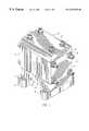
- FIG. 1is a perspective view of an air driven double diaphragm pump.
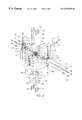
- FIG. 2is an exploded assembly view of the pump of FIG.
- FIG. 3is a cross-sectional view of the pump of FIG. 1 .
- FIG. 4is a front view of a ball valve.
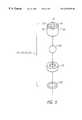
- FIG. 5is an exploded assembly of the ball valve of FIG. 4 .
- FIG. 6is a cross-sectional view of the ball valve of FIG. 4 taken along line 6 — 6 .
- FIG. 7is a plan view of a diaphragm.
- FIG. 8is a cross-sectional view of the diaphragm of FIG. 7 .
- FIG. 9is a Belleville washer and fastener assembly in cross-section.
- FIG. 10is an exploded assembly view of a diaphragm and pump chamber in perspective.
- FIGS. 1, 2 and 3an driven diaphragm pump is illustrated in FIGS. 1, 2 and 3 .
- the pumpis contemplated to be PTFE or other appropriate polymer.
- the pumpincludes an air motor center section 10 which provides the actuator system for the pump.
- One such system applicable to the present inventionis disclosed in U.S. Pat. No. 5,607,290, issued Mar. 4, 1997, the disclosure of which is incorporated herein by reference.
- Two opposed air chambers 12 and 14are included as part of the air motor 10 .
- the air chambers 12 and 14face in opposite directions with an air valve 16 therebetween. Components of the air valve illustrated in FIG.
- valve cylinder 22with an unbalanced valve piston 24 held in place by an end cap 26 sealed with an O-ring 28 .
- the valve cylinder 22is held to the side of the body of the air valve 16 by fasteners 30 .
- An exhaust defuser 32is found to one side of the air valve assembly while an inlet coupling 34 extends to the air valve 16 from the other side.
- Pump chambers 36 and 38are positioned to either side of the air motor 10 and are arranged to mate with the air chambers 12 and 14 , respectively, to define pumping cavities 40 and 42 divided by diaphragms 44 and 46 .
- the pump chambers 36 and 38each include inlet ball valves 48 and 50 and outlet ball valves 52 and 54 .
- An inlet manifold 56extends across the bottom of the pump chambers 36 and 38 .
- Feet 58 and 60support the inlet manifold 56 and in turn the entire pump.
- An outlet manifold 62extends across the top of the pump chambers 36 and 38 .
- a general sealing between the inlet manifold 56 , the outlet manifold 62 and the two pump chambers 36 and 38is provided by O-rings 64 set within circular grooves in the pump chambers 36 and 38 .
- the ball valves 48 , 50 , 52 and 54each include a ball 66 , a ball cage 68 and a seat 70 .
- the ball cage 68is cylindrical in shape with four holes 72 , 74 , 76 and 78 , which are equiangularly spaced about and parallel to a central axis of the ball cage 68 .
- a cavity 80extends part way through the cage 68 and has a domed inner end.
- the cavity 80intersects the holes 72 - 78 to provide passageways fully through the cage 68 .
- the cavity 80is configured such that there is a 0.016′′ diametrical clearance between the ball 66 and the cage 68 measured at room temperature.
- clearancemay be at a minimum.
- some clearanceadvantageously prevents sticking of the components because of thermal expansion. By maintaining the clearance at a minimum, ball chatter as it is seating is kept to a minimum. This impacts both noise and efficiency of the pump.
- the lift of the ball 66 within the cage 68is kept at 0.100′′ from the seated position. Even greater lift can positively impact on flow rates. However, with increased lift, self-priming performance decreases.
- the ratio of the diametrical clearanceestablishes a relevance of the two measurements without reference to scale. Depending on the demands for self-priming, the lift can increase in proportion to the diametrical clearance.
- valve seats 70are shown to each include a cylindrical groove in which an O-ring 82 seats.
- the seats 70are positioned on the inlet manifold 56 .
- the outlets ball valves 52 and 54the seats 70 seal with the pump chambers 36 and 38 .
- the surfaces directly contacted by the O-rings 82are polished to at least 10R A such that the elastomeric O-rings 82 seal completely with the PTFE surfaces.
- the seals thus formedmay be reversed in the sense that the O-rings are positioned in grooves on the body parts of the pump and the polished surfaces are provided by the seats 70 .
- a hub 84is located centrally in each of the circular diaphragms 44 and 46 .
- the diaphragmsare integrally molded with a central insert which is a metal stud 86 .
- the stud 86includes a head 88 with circumferential ribs 90 which are shown to be in the nature of cut threads.
- the stud 86also includes a threaded shank 92 which extends through piston elements 94 and fastens into the center shaft 20 extending through the air motor center section
- An annular sheet 96extends outwardly from the hub 84 to form the body of the diaphragm.
- a semi-circular corrugation 98extends about the periphery of the annular sheet 96 to receive an O-ring 100 .
- the air chambers 12 and 14 and the pump chambers 36 and 38include annular grooves to receive the corrugations 98 and the O-rings 100 on the diaphragms 44 and 46 as best seen in FIG. 3 .
- cylindrical flanges 102are provided on the diaphragms 44 and 46 .
- Cylindrical bosses 104are found on the inner faces of the pump chambers 36 and 38 facing toward the air motor center section 10 to receive the cylindrical flanges 102 .
- the bosses 104facilitate placement of the diaphragms 44 and 46 through cooperation with the cylindrical flanges 102 .
- the diaphragms 44 and 46are typically the most wear prone components within an air driven double diaphragm pump. Ultimately, such diaphragms will fail due to repeated flexure. Another point of possible failure of diaphragms according to the current design is the extraction of the stud 86 from the hub 84 . Force is experienced in this assembly when the diaphragm is operating in the suction stroke. As the air chamber on the other side of the pump is being pressurized, the center shaft 20 is pulling on the stud 86 and in turn the hub 84 . Over time, the head 88 can be pulled from the hub 84 during such a stroke.
- the head 88 and the hub 84can be configured along with the circumferential ribs 90 such that failure of the diaphragm due to extraction of the stud 86 can provide planned obsolescence at a point prior to rupture of the annular sheet 96 .
- the hub 84 and annular sheet 96are all integral, the extraction of the stud 86 does not break the barrier between the air side and the fluid side of the pumping cavities. Once extracted, the center shaft 20 will not be forced to follow the diaphragm when pressurized air is introduced. Consequently, the pump will cease to shift and will stall without leakage into the air side of the pump.
- the inlet manifold 56 and the outlet manifold 62are similarly constructed.
- the inlet manifold 56is relatively flat, top and bottom, and includes a cylindrical inlet 106 with holes 108 and 110 to provide access to the inlet ball valves 48 and 50 .
- the flat bottomreceives the feet 58 and 60 while the flat top receives the pump chambers 36 and 38 .
- a polished surface areais provided for sealing with the seats 70 of the inlet ball valves 48 and 50 .
- bolt holes 112extend vertically through the inlet manifold 56 .
- the outlet manifoldincludes a cylindrical outlet 114 communicating with the outlet ball valves 52 and 54 through holes 116 and 118 .
- the upper surfaceis rounded and has bolt holes 120 which are aligned with the bolt holes 112 in the inlet manifold 56 .
- Holes 122extend through the pump chambers 36 and 38 to align with the bolt holes 112 and 120 .
- Bolt holes 124are also in the feet 58 and 60 and are countersunk. Other anchoring holes 126 are positioned outwardly of the bolt holes 124 in the feet 58 and 60 to allow fastening of the pump to a supporting surface.
- the pump chambers 36 and 38include bolt holes 128 extending through the four corners. They are arranged outwardly of the air motor 10 so that the air motor 10 will not interfere with fasteners extending through these holes 128 .
- the pumpis held together by a cross bolt assembly. Fasteners extend in one direction through the bolt holes 128 in the pump chambers 36 and 38 to compress the pump chambers together with the air motor 10 therebetween.
- the fasteners extending through the bolt holes 128include tie-rods 130 which are made from a 70% glass filled epoxy vinyl ester. Shoulders are defined on the tie-rods 130 to place them in tension by nuts 132 .
- the nuts 132are made from 40% glass filled polyphenylene sulfide.
- tie-rods 130are threaded on either end to receive the nuts 132 .
- tie-rods 134extend vertically through the outlet manifold 62 , the inlet manifold 56 and the pump chambers 36 and 38 .
- Nuts 136are similarly associated with the tie-rods 134 .
- Countersunk bolt holes in the feetaccommodate the nuts 132 so that the feet can provide a flat mounting surface.
- FIG. 9illustrates the detail of these conical washers 138 in association with flat washers 140 and the nuts 132 ( 136 ).
- the washersare made of polyetheretherketone reinforced with glass or carbon fiber.
- Plates 142 and 144are arranged to either side of the air motor center section 10 .
- Grooves 146are placed on the inner sides of the pump chambers 36 and 38 and the inlet manifold 56 and outlet manifold 62 to receive the periphery of each of the plates 142 and 144 .
- An outlet 148provides a coupling which can accommodate a conduit for directing exhausted air to a remote location for clean room applications.
- the inlet coupling 34also extends through the plate 144 .
Landscapes
- Engineering & Computer Science (AREA)
- Mechanical Engineering (AREA)
- General Engineering & Computer Science (AREA)
- Reciprocating Pumps (AREA)
Abstract
Description
Claims (4)
Priority Applications (3)
| Application Number | Priority Date | Filing Date | Title |
|---|---|---|---|
| US09/115,287US6257845B1 (en) | 1998-07-14 | 1998-07-14 | Air driven pumps and components therefor |
| CA002277585ACA2277585A1 (en) | 1998-07-14 | 1999-07-13 | Air drive pumps and components therefor |
| US09/478,733US6142749A (en) | 1998-07-14 | 2000-01-06 | Air driven pumps and components therefor |
Applications Claiming Priority (1)
| Application Number | Priority Date | Filing Date | Title |
|---|---|---|---|
| US09/115,287US6257845B1 (en) | 1998-07-14 | 1998-07-14 | Air driven pumps and components therefor |
Related Child Applications (1)
| Application Number | Title | Priority Date | Filing Date |
|---|---|---|---|
| US09/478,733DivisionUS6142749A (en) | 1998-07-14 | 2000-01-06 | Air driven pumps and components therefor |
Publications (1)
| Publication Number | Publication Date |
|---|---|
| US6257845B1true US6257845B1 (en) | 2001-07-10 |
Family
ID=22360388
Family Applications (2)
| Application Number | Title | Priority Date | Filing Date |
|---|---|---|---|
| US09/115,287Expired - LifetimeUS6257845B1 (en) | 1998-07-14 | 1998-07-14 | Air driven pumps and components therefor |
| US09/478,733Expired - LifetimeUS6142749A (en) | 1998-07-14 | 2000-01-06 | Air driven pumps and components therefor |
Family Applications After (1)
| Application Number | Title | Priority Date | Filing Date |
|---|---|---|---|
| US09/478,733Expired - LifetimeUS6142749A (en) | 1998-07-14 | 2000-01-06 | Air driven pumps and components therefor |
Country Status (2)
| Country | Link |
|---|---|
| US (2) | US6257845B1 (en) |
| CA (1) | CA2277585A1 (en) |
Cited By (25)
| Publication number | Priority date | Publication date | Assignee | Title |
|---|---|---|---|---|
| US6619932B2 (en)* | 2001-01-23 | 2003-09-16 | Yamada T.S. Co. Ltd. | Restarting device of a pump change-over valve which induces a pressure difference within the pump change-over valve to remove the latter from an intermediate stalled position |
| US6644940B2 (en)* | 2000-12-18 | 2003-11-11 | Yamada Corporation | Restarting device for a fluid operated double diaphragm piston pump |
| US20040047748A1 (en)* | 2002-09-06 | 2004-03-11 | Ingersoll-Rand Company | Double diaphragm pump including spool valve air motor |
| US20040177750A1 (en)* | 2003-03-11 | 2004-09-16 | Ingersoll-Rand Company | Method of producing a pump |
| US20040182237A1 (en)* | 2003-03-19 | 2004-09-23 | Ingersoll-Ranch Company | Connecting configuration for a diaphragm in a diaphragm pump |
| WO2005027190A2 (en) | 2003-09-08 | 2005-03-24 | New Scale Technologies, Inc. | Ultrasonic lead screw motor |
| US6938905B1 (en) | 2004-11-05 | 2005-09-06 | Haiming Tsai | Hand truck |
| US20050258714A1 (en)* | 2003-09-08 | 2005-11-24 | David Henderson | Mechanism comprised of ultrasonic lead screw motor |
| US20060049720A1 (en)* | 2003-09-08 | 2006-03-09 | David Henderson | Mechanism comprised of ultrasonic lead screw motor |
| US20060082950A1 (en)* | 2004-10-18 | 2006-04-20 | Wilden Pump And Engineering Llc | Air valve for an air driven reciprocating device |
| US20060104829A1 (en)* | 2004-11-17 | 2006-05-18 | Reed David A | Control system for an air operated diaphragm pump |
| US20060181168A1 (en)* | 2003-04-14 | 2006-08-17 | Hargraves Donald E | Pump motor with bearing preload |
| US20070092386A1 (en)* | 2005-10-24 | 2007-04-26 | Reed David A | Method and control system for a pump |
| US7299776B1 (en) | 2005-10-11 | 2007-11-27 | Baker W Howard | Valve assembly for an internal combustion engine |
| US20080253902A1 (en)* | 2005-04-04 | 2008-10-16 | Fernando Erriu | Fluidic Kinetic Energy Recovery Device |
| US20090202361A1 (en)* | 2004-11-17 | 2009-08-13 | Proportion, Inc. | Control system for an air operated diaphragm pump |
| US20130115117A1 (en)* | 2010-05-18 | 2013-05-09 | Alberto Gonzalez-Moratiel Alvarez | Double-Membrane Central-Flow Pump |
| US8469681B2 (en)* | 2009-04-29 | 2013-06-25 | Flotronic Pumps Limited | Double-diaphragm pumps |
| US8496451B2 (en) | 2010-06-21 | 2013-07-30 | Wilden Pump And Engineering Llc | Pump diaphragm |
| US9976545B2 (en) | 2014-01-31 | 2018-05-22 | Wilden Pump And Engineering Llc | Air operated pump |
| US10077763B2 (en) | 2015-03-25 | 2018-09-18 | Wilden Pump And Engineering Llc | Air operated pump |
| US10422331B2 (en) | 2016-08-12 | 2019-09-24 | Ingersoll-Rand Company | One piece diaphragm |
| US12116994B2 (en) | 2018-10-11 | 2024-10-15 | Psg Germany Gmbh | Diaphragm pump |
| US20240401581A1 (en)* | 2017-07-12 | 2024-12-05 | Blue-White Industries, Ltd. | Multiple diaphragm pump |
| US12345248B2 (en) | 2019-03-13 | 2025-07-01 | Psg Germany Gmbh | Valve assemblies for a diaphragm pump |
Families Citing this family (20)
| Publication number | Priority date | Publication date | Assignee | Title |
|---|---|---|---|---|
| US6957952B1 (en) | 1998-10-05 | 2005-10-25 | Trebor International, Inc. | Fiber optic system for detecting pump cycles |
| US6106246A (en) | 1998-10-05 | 2000-08-22 | Trebor International, Inc. | Free-diaphragm pump |
| US6695593B1 (en) | 1998-10-05 | 2004-02-24 | Trebor International, Inc. | Fiber optics systems for high purity pump diagnostics |
| US7134849B1 (en) | 2003-04-22 | 2006-11-14 | Trebor International, Inc. | Molded disposable pneumatic pump |
| US7600532B2 (en)* | 2006-11-01 | 2009-10-13 | Ingersoll Rand Company | Check valve having integrally formed seat and seal body |
| KR101667067B1 (en) | 2008-10-22 | 2016-10-17 | 그라코 미네소타 인크. | Portable airless sprayer |
| US8887620B2 (en)* | 2010-06-22 | 2014-11-18 | Graco Minnesota Inc. | Diaphragm installation tool |
| CN103047128B (en)* | 2013-01-08 | 2015-07-01 | 曹雷钢 | Reversing valve for pneumatic diaphragm pump |
| US10036382B2 (en)* | 2013-05-10 | 2018-07-31 | White Knight Fluid Handling Inc. | Pneumatic reciprocating fluid pump with improved check valve assembly, and related methods |
| US9638185B2 (en)* | 2014-02-07 | 2017-05-02 | Graco Minnesota Inc. | Pulseless positive displacement pump and method of pulselessly displacing fluid |
| USD782541S1 (en)* | 2015-10-06 | 2017-03-28 | Graco Minnesota Inc. | Diaphragm pump |
| US11007545B2 (en) | 2017-01-15 | 2021-05-18 | Graco Minnesota Inc. | Handheld airless paint sprayer repair |
| US11022106B2 (en) | 2018-01-09 | 2021-06-01 | Graco Minnesota Inc. | High-pressure positive displacement plunger pump |
| CN112368082B (en) | 2018-04-10 | 2022-11-08 | 固瑞克明尼苏达有限公司 | Handheld airless sprayer for paints and other coatings |
| US11471660B2 (en)* | 2018-10-25 | 2022-10-18 | Covidien Lp | Vacuum driven suction and irrigation system |
| EP3976270A1 (en) | 2019-05-31 | 2022-04-06 | Graco Minnesota Inc. | Handheld fluid sprayer |
| AU2021246059A1 (en) | 2020-03-31 | 2022-10-06 | Graco Minnesota Inc. | Electrically operated displacement pump |
| EP4127475B1 (en) | 2020-03-31 | 2024-10-23 | Graco Minnesota Inc. | Electrically operated pump for a plural component spray system |
| US10968903B1 (en) | 2020-06-04 | 2021-04-06 | Graco Minnesota Inc. | Handheld sanitary fluid sprayer having resilient polymer pump cylinder |
| US10926275B1 (en) | 2020-06-25 | 2021-02-23 | Graco Minnesota Inc. | Electrostatic handheld sprayer |
Citations (14)
| Publication number | Priority date | Publication date | Assignee | Title |
|---|---|---|---|---|
| US4242941A (en) | 1979-05-14 | 1981-01-06 | Wilden Pump & Engineering Co. | Actuator valve |
| US4247264A (en) | 1979-04-13 | 1981-01-27 | Wilden Pump & Engineering Co. | Air driven diaphragm pump |
| USD275858S (en) | 1982-06-01 | 1984-10-09 | Wilden Pump & Engineering Co. | Double diaphragm pump |
| US4549467A (en) | 1983-08-03 | 1985-10-29 | Wilden Pump & Engineering Co. | Actuator valve |
| USD294946S (en) | 1984-08-06 | 1988-03-29 | Wilden Pump & Engineering Co. | Air driven diaphragm pump |
| USD294947S (en) | 1984-08-06 | 1988-03-29 | Wilden Pump & Engineering Co. | Air driven diaphragm pump |
| US5145336A (en) | 1990-03-13 | 1992-09-08 | Knf Neuberger Gmbh | Diaphragm pump with reinforced diaphragm |
| US5169296A (en) | 1989-03-10 | 1992-12-08 | Wilden James K | Air driven double diaphragm pump |
| US5213485A (en) | 1989-03-10 | 1993-05-25 | Wilden James K | Air driven double diaphragm pump |
| US5240390A (en) | 1992-03-27 | 1993-08-31 | Graco Inc. | Air valve actuator for reciprocable machine |
| US5567118A (en) | 1995-02-14 | 1996-10-22 | Itt Fluid Technology Corporation | Non-lubricated, air-actuated, pump-operating, shuttle valve arrangement, in a reciprocating pump |
| US5649809A (en) | 1994-12-08 | 1997-07-22 | Abel Gmbh & Co. Handels-Und Verwaltungsgesllschaft | Crankshaft and piston rod connection for a double diaphragm pump |
| US5927954A (en) | 1996-05-17 | 1999-07-27 | Wilden Pump & Engineering Co. | Amplified pressure air driven diaphragm pump and pressure relief value therefor |
| US5957670A (en) | 1997-08-26 | 1999-09-28 | Wilden Pump & Engineering Co. | Air driven diaphragm pump |
- 1998
- 1998-07-14USUS09/115,287patent/US6257845B1/ennot_activeExpired - Lifetime
- 1999
- 1999-07-13CACA002277585Apatent/CA2277585A1/ennot_activeAbandoned
- 2000
- 2000-01-06USUS09/478,733patent/US6142749A/ennot_activeExpired - Lifetime
Patent Citations (14)
| Publication number | Priority date | Publication date | Assignee | Title |
|---|---|---|---|---|
| US4247264A (en) | 1979-04-13 | 1981-01-27 | Wilden Pump & Engineering Co. | Air driven diaphragm pump |
| US4242941A (en) | 1979-05-14 | 1981-01-06 | Wilden Pump & Engineering Co. | Actuator valve |
| USD275858S (en) | 1982-06-01 | 1984-10-09 | Wilden Pump & Engineering Co. | Double diaphragm pump |
| US4549467A (en) | 1983-08-03 | 1985-10-29 | Wilden Pump & Engineering Co. | Actuator valve |
| USD294946S (en) | 1984-08-06 | 1988-03-29 | Wilden Pump & Engineering Co. | Air driven diaphragm pump |
| USD294947S (en) | 1984-08-06 | 1988-03-29 | Wilden Pump & Engineering Co. | Air driven diaphragm pump |
| US5213485A (en) | 1989-03-10 | 1993-05-25 | Wilden James K | Air driven double diaphragm pump |
| US5169296A (en) | 1989-03-10 | 1992-12-08 | Wilden James K | Air driven double diaphragm pump |
| US5145336A (en) | 1990-03-13 | 1992-09-08 | Knf Neuberger Gmbh | Diaphragm pump with reinforced diaphragm |
| US5240390A (en) | 1992-03-27 | 1993-08-31 | Graco Inc. | Air valve actuator for reciprocable machine |
| US5649809A (en) | 1994-12-08 | 1997-07-22 | Abel Gmbh & Co. Handels-Und Verwaltungsgesllschaft | Crankshaft and piston rod connection for a double diaphragm pump |
| US5567118A (en) | 1995-02-14 | 1996-10-22 | Itt Fluid Technology Corporation | Non-lubricated, air-actuated, pump-operating, shuttle valve arrangement, in a reciprocating pump |
| US5927954A (en) | 1996-05-17 | 1999-07-27 | Wilden Pump & Engineering Co. | Amplified pressure air driven diaphragm pump and pressure relief value therefor |
| US5957670A (en) | 1997-08-26 | 1999-09-28 | Wilden Pump & Engineering Co. | Air driven diaphragm pump |
Cited By (37)
| Publication number | Priority date | Publication date | Assignee | Title |
|---|---|---|---|---|
| US6644940B2 (en)* | 2000-12-18 | 2003-11-11 | Yamada Corporation | Restarting device for a fluid operated double diaphragm piston pump |
| US6619932B2 (en)* | 2001-01-23 | 2003-09-16 | Yamada T.S. Co. Ltd. | Restarting device of a pump change-over valve which induces a pressure difference within the pump change-over valve to remove the latter from an intermediate stalled position |
| US20040047748A1 (en)* | 2002-09-06 | 2004-03-11 | Ingersoll-Rand Company | Double diaphragm pump including spool valve air motor |
| US6901960B2 (en) | 2002-09-06 | 2005-06-07 | Ingersoll-Rand Company | Double diaphragm pump including spool valve air motor |
| US20040177750A1 (en)* | 2003-03-11 | 2004-09-16 | Ingersoll-Rand Company | Method of producing a pump |
| US6865981B2 (en) | 2003-03-11 | 2005-03-15 | Ingersoll-Rand Company | Method of producing a pump |
| US20040182237A1 (en)* | 2003-03-19 | 2004-09-23 | Ingersoll-Ranch Company | Connecting configuration for a diaphragm in a diaphragm pump |
| US6883417B2 (en) | 2003-03-19 | 2005-04-26 | Ingersoll-Rand Company | Connecting configuration for a diaphragm in a diaphragm pump |
| US20060181168A1 (en)* | 2003-04-14 | 2006-08-17 | Hargraves Donald E | Pump motor with bearing preload |
| WO2005027190A2 (en) | 2003-09-08 | 2005-03-24 | New Scale Technologies, Inc. | Ultrasonic lead screw motor |
| US7309943B2 (en) | 2003-09-08 | 2007-12-18 | New Scale Technologies, Inc. | Mechanism comprised of ultrasonic lead screw motor |
| US20060049720A1 (en)* | 2003-09-08 | 2006-03-09 | David Henderson | Mechanism comprised of ultrasonic lead screw motor |
| US7339306B2 (en) | 2003-09-08 | 2008-03-04 | New Scale Technologies Inc. | Mechanism comprised of ultrasonic lead screw motor |
| US20050258714A1 (en)* | 2003-09-08 | 2005-11-24 | David Henderson | Mechanism comprised of ultrasonic lead screw motor |
| US7170214B2 (en) | 2003-09-08 | 2007-01-30 | New Scale Technologies, Inc. | Mechanism comprised of ultrasonic lead screw motor |
| US8047222B2 (en) | 2004-10-18 | 2011-11-01 | Wilden Pump And Engineering Llc | Air valve for an air driven reciprocating device |
| WO2006044915A2 (en) | 2004-10-18 | 2006-04-27 | Wilden Pump And Engineering Llc | Air valve for an air driven reciprocating device |
| US20060082950A1 (en)* | 2004-10-18 | 2006-04-20 | Wilden Pump And Engineering Llc | Air valve for an air driven reciprocating device |
| US6938905B1 (en) | 2004-11-05 | 2005-09-06 | Haiming Tsai | Hand truck |
| US20060104829A1 (en)* | 2004-11-17 | 2006-05-18 | Reed David A | Control system for an air operated diaphragm pump |
| US8292600B2 (en) | 2004-11-17 | 2012-10-23 | Proportion-Air, Incorporated | Control system for an air operated diaphragm pump |
| US7517199B2 (en) | 2004-11-17 | 2009-04-14 | Proportion Air Incorporated | Control system for an air operated diaphragm pump |
| US20090202361A1 (en)* | 2004-11-17 | 2009-08-13 | Proportion, Inc. | Control system for an air operated diaphragm pump |
| US20080253902A1 (en)* | 2005-04-04 | 2008-10-16 | Fernando Erriu | Fluidic Kinetic Energy Recovery Device |
| US7299776B1 (en) | 2005-10-11 | 2007-11-27 | Baker W Howard | Valve assembly for an internal combustion engine |
| US7658598B2 (en) | 2005-10-24 | 2010-02-09 | Proportionair, Incorporated | Method and control system for a pump |
| US20070092386A1 (en)* | 2005-10-24 | 2007-04-26 | Reed David A | Method and control system for a pump |
| US8469681B2 (en)* | 2009-04-29 | 2013-06-25 | Flotronic Pumps Limited | Double-diaphragm pumps |
| US20130115117A1 (en)* | 2010-05-18 | 2013-05-09 | Alberto Gonzalez-Moratiel Alvarez | Double-Membrane Central-Flow Pump |
| US8858195B2 (en)* | 2010-05-18 | 2014-10-14 | Samoa Industrial S.A. | Double-membrane central-flow pump |
| US8496451B2 (en) | 2010-06-21 | 2013-07-30 | Wilden Pump And Engineering Llc | Pump diaphragm |
| US9976545B2 (en) | 2014-01-31 | 2018-05-22 | Wilden Pump And Engineering Llc | Air operated pump |
| US10077763B2 (en) | 2015-03-25 | 2018-09-18 | Wilden Pump And Engineering Llc | Air operated pump |
| US10422331B2 (en) | 2016-08-12 | 2019-09-24 | Ingersoll-Rand Company | One piece diaphragm |
| US20240401581A1 (en)* | 2017-07-12 | 2024-12-05 | Blue-White Industries, Ltd. | Multiple diaphragm pump |
| US12116994B2 (en) | 2018-10-11 | 2024-10-15 | Psg Germany Gmbh | Diaphragm pump |
| US12345248B2 (en) | 2019-03-13 | 2025-07-01 | Psg Germany Gmbh | Valve assemblies for a diaphragm pump |
Also Published As
| Publication number | Publication date |
|---|---|
| CA2277585A1 (en) | 2000-01-14 |
| US6142749A (en) | 2000-11-07 |
Similar Documents
| Publication | Publication Date | Title |
|---|---|---|
| US6257845B1 (en) | Air driven pumps and components therefor | |
| US5171136A (en) | Fluid flow control device | |
| EP1956242B1 (en) | Diaphragm pump | |
| EP1490598B1 (en) | Head pressure relief assembly | |
| US4978285A (en) | Reed valve for hermetic compressor | |
| US3354831A (en) | Piston diaphragm pump | |
| WO1994025756A1 (en) | High pressure pump with loaded compression rods and method | |
| US4278406A (en) | Electromagnetic pump | |
| US4239463A (en) | Reciprocating plunger pump with improved liquid end valve assembly | |
| US5803122A (en) | Reciprocating pump valve | |
| JPH1162840A (en) | Air pump | |
| US3431865A (en) | Pump with concentric valve means | |
| US3276389A (en) | Balanced pressure pump | |
| US5498138A (en) | Sampling pump having a fluid motor pressure regulator | |
| US8226381B2 (en) | Check valve having integrally formed seat and seal body | |
| US20120128509A1 (en) | Reciprocating Compressor | |
| KR100291161B1 (en) | Diaphragm pump | |
| US5897305A (en) | Valve assembly for compressors | |
| EP1322863B1 (en) | Piston stroke limiting device for a reciprocating compressor | |
| KR100491065B1 (en) | Reciprocating Air Operated Pump | |
| CN207935056U (en) | Fluid chamber component, diaphragm pump and the purifying drinking appliance of diaphragm pump | |
| CN111878367A (en) | Diaphragm wear-resistant and leakage-proof structure in diaphragm pump head and diaphragm pump | |
| CN1014740B (en) | Pressure reducing device for compressor | |
| US20150219084A1 (en) | Compressor | |
| CN223035237U (en) | Plunger pump head and plunger pump |
Legal Events
| Date | Code | Title | Description |
|---|---|---|---|
| AS | Assignment | Owner name:WILDEN PUMP & ENGINEERING CO., CALIFORNIA Free format text:ASSIGNMENT OF ASSIGNORS INTEREST;ASSIGNORS:JACK, ROBERT F.;FORMAN, ERIC L.;HUMPHRIES, JAMES E.;AND OTHERS;REEL/FRAME:009597/0511 Effective date:19981008 | |
| STCF | Information on status: patent grant | Free format text:PATENTED CASE | |
| FEPP | Fee payment procedure | Free format text:PAYOR NUMBER ASSIGNED (ORIGINAL EVENT CODE: ASPN); ENTITY STATUS OF PATENT OWNER: LARGE ENTITY | |
| AS | Assignment | Owner name:DOVER RESOURCES PUMP ENGINEERING COMPANY, CALIFORN Free format text:ARTICLES OF INCORPORATION;ASSIGNOR:WILDEN PUMP AND ENGINEERING COMPANY;REEL/FRAME:014373/0038 Effective date:19980806 Owner name:WILDEN PUMP AND ENGINEERING COMPANY, DELAWARE Free format text:MERGER;ASSIGNOR:DOVER RESOURCES PUMP ENGINEERING COMPANY;REEL/FRAME:014373/0001 Effective date:19980806 Owner name:WILDEN PUMP AND ENGINEERING LLC, DELAWARE Free format text:ASSIGNMENT OF ASSIGNORS INTEREST;ASSIGNOR:WILDEN PUMP AND ENGINEERING COMPANY;REEL/FRAME:014373/0102 Effective date:20021223 | |
| FPAY | Fee payment | Year of fee payment:4 | |
| REMI | Maintenance fee reminder mailed | ||
| FPAY | Fee payment | Year of fee payment:8 | |
| SULP | Surcharge for late payment | Year of fee payment:7 | |
| FPAY | Fee payment | Year of fee payment:12 |