US6257492B1 - Combination hand-held and counter-top omni-directional scanner - Google Patents
Combination hand-held and counter-top omni-directional scannerDownload PDFInfo
- Publication number
- US6257492B1 US6257492B1US09/323,292US32329299AUS6257492B1US 6257492 B1US6257492 B1US 6257492B1US 32329299 AUS32329299 AUS 32329299AUS 6257492 B1US6257492 B1US 6257492B1
- Authority
- US
- United States
- Prior art keywords
- scanning
- base unit
- head
- bar code
- compact
- Prior art date
- Legal status (The legal status is an assumption and is not a legal conclusion. Google has not performed a legal analysis and makes no representation as to the accuracy of the status listed.)
- Expired - Fee Related
Links
Images


Classifications
- G—PHYSICS
- G07—CHECKING-DEVICES
- G07G—REGISTERING THE RECEIPT OF CASH, VALUABLES, OR TOKENS
- G07G1/00—Cash registers
- G07G1/0036—Checkout procedures
- G07G1/0045—Checkout procedures with a code reader for reading of an identifying code of the article to be registered, e.g. barcode reader or radio-frequency identity [RFID] reader
- A—HUMAN NECESSITIES
- A47—FURNITURE; DOMESTIC ARTICLES OR APPLIANCES; COFFEE MILLS; SPICE MILLS; SUCTION CLEANERS IN GENERAL
- A47F—SPECIAL FURNITURE, FITTINGS, OR ACCESSORIES FOR SHOPS, STOREHOUSES, BARS, RESTAURANTS OR THE LIKE; PAYING COUNTERS
- A47F9/00—Shop, bar, bank or like counters
- A47F9/02—Paying counters
- A47F9/04—Check-out counters, e.g. for self-service stores
- A47F9/046—Arrangement of recording means in or on check-out counters
- A47F9/047—Arrangement of recording means in or on check-out counters for recording self-service articles without cashier or assistant
- B—PERFORMING OPERATIONS; TRANSPORTING
- B25—HAND TOOLS; PORTABLE POWER-DRIVEN TOOLS; MANIPULATORS
- B25H—WORKSHOP EQUIPMENT, e.g. FOR MARKING-OUT WORK; STORAGE MEANS FOR WORKSHOPS
- B25H5/00—Tool, instrument or work supports or storage means used in association with vehicles; Workers' supports, e.g. mechanics' creepers
- B—PERFORMING OPERATIONS; TRANSPORTING
- B66—HOISTING; LIFTING; HAULING
- B66F—HOISTING, LIFTING, HAULING OR PUSHING, NOT OTHERWISE PROVIDED FOR, e.g. DEVICES WHICH APPLY A LIFTING OR PUSHING FORCE DIRECTLY TO THE SURFACE OF A LOAD
- B66F7/00—Lifting frames, e.g. for lifting vehicles; Platform lifts
- B66F7/28—Constructional details, e.g. end stops, pivoting supporting members, sliding runners adjustable to load dimensions
- G—PHYSICS
- G02—OPTICS
- G02B—OPTICAL ELEMENTS, SYSTEMS OR APPARATUS
- G02B26/00—Optical devices or arrangements for the control of light using movable or deformable optical elements
- G02B26/08—Optical devices or arrangements for the control of light using movable or deformable optical elements for controlling the direction of light
- G02B26/10—Scanning systems
- G02B26/106—Scanning systems having diffraction gratings as scanning elements, e.g. holographic scanners
- G—PHYSICS
- G06—COMPUTING OR CALCULATING; COUNTING
- G06K—GRAPHICAL DATA READING; PRESENTATION OF DATA; RECORD CARRIERS; HANDLING RECORD CARRIERS
- G06K17/00—Methods or arrangements for effecting co-operative working between equipments covered by two or more of main groups G06K1/00 - G06K15/00, e.g. automatic card files incorporating conveying and reading operations
- G06K17/0022—Methods or arrangements for effecting co-operative working between equipments covered by two or more of main groups G06K1/00 - G06K15/00, e.g. automatic card files incorporating conveying and reading operations arrangements or provisions for transferring data to distant stations, e.g. from a sensing device
- G—PHYSICS
- G06—COMPUTING OR CALCULATING; COUNTING
- G06K—GRAPHICAL DATA READING; PRESENTATION OF DATA; RECORD CARRIERS; HANDLING RECORD CARRIERS
- G06K7/00—Methods or arrangements for sensing record carriers, e.g. for reading patterns
- G06K7/10—Methods or arrangements for sensing record carriers, e.g. for reading patterns by electromagnetic radiation, e.g. optical sensing; by corpuscular radiation
- G06K7/10544—Methods or arrangements for sensing record carriers, e.g. for reading patterns by electromagnetic radiation, e.g. optical sensing; by corpuscular radiation by scanning of the records by radiation in the optical part of the electromagnetic spectrum
- G06K7/10554—Moving beam scanning
- G06K7/10564—Light sources
- G06K7/10584—Source control
- G—PHYSICS
- G06—COMPUTING OR CALCULATING; COUNTING
- G06K—GRAPHICAL DATA READING; PRESENTATION OF DATA; RECORD CARRIERS; HANDLING RECORD CARRIERS
- G06K7/00—Methods or arrangements for sensing record carriers, e.g. for reading patterns
- G06K7/10—Methods or arrangements for sensing record carriers, e.g. for reading patterns by electromagnetic radiation, e.g. optical sensing; by corpuscular radiation
- G06K7/10544—Methods or arrangements for sensing record carriers, e.g. for reading patterns by electromagnetic radiation, e.g. optical sensing; by corpuscular radiation by scanning of the records by radiation in the optical part of the electromagnetic spectrum
- G06K7/10554—Moving beam scanning
- G06K7/10594—Beam path
- G06K7/10603—Basic scanning using moving elements
- G06K7/10663—Basic scanning using moving elements using hologram
- G—PHYSICS
- G06—COMPUTING OR CALCULATING; COUNTING
- G06K—GRAPHICAL DATA READING; PRESENTATION OF DATA; RECORD CARRIERS; HANDLING RECORD CARRIERS
- G06K7/00—Methods or arrangements for sensing record carriers, e.g. for reading patterns
- G06K7/10—Methods or arrangements for sensing record carriers, e.g. for reading patterns by electromagnetic radiation, e.g. optical sensing; by corpuscular radiation
- G06K7/10544—Methods or arrangements for sensing record carriers, e.g. for reading patterns by electromagnetic radiation, e.g. optical sensing; by corpuscular radiation by scanning of the records by radiation in the optical part of the electromagnetic spectrum
- G06K7/10554—Moving beam scanning
- G06K7/10594—Beam path
- G06K7/10603—Basic scanning using moving elements
- G06K7/10673—Parallel lines
- G—PHYSICS
- G06—COMPUTING OR CALCULATING; COUNTING
- G06K—GRAPHICAL DATA READING; PRESENTATION OF DATA; RECORD CARRIERS; HANDLING RECORD CARRIERS
- G06K7/00—Methods or arrangements for sensing record carriers, e.g. for reading patterns
- G06K7/10—Methods or arrangements for sensing record carriers, e.g. for reading patterns by electromagnetic radiation, e.g. optical sensing; by corpuscular radiation
- G06K7/10544—Methods or arrangements for sensing record carriers, e.g. for reading patterns by electromagnetic radiation, e.g. optical sensing; by corpuscular radiation by scanning of the records by radiation in the optical part of the electromagnetic spectrum
- G06K7/10554—Moving beam scanning
- G06K7/10594—Beam path
- G06K7/10683—Arrangement of fixed elements
- G06K7/10693—Arrangement of fixed elements for omnidirectional scanning
- G—PHYSICS
- G06—COMPUTING OR CALCULATING; COUNTING
- G06K—GRAPHICAL DATA READING; PRESENTATION OF DATA; RECORD CARRIERS; HANDLING RECORD CARRIERS
- G06K7/00—Methods or arrangements for sensing record carriers, e.g. for reading patterns
- G06K7/10—Methods or arrangements for sensing record carriers, e.g. for reading patterns by electromagnetic radiation, e.g. optical sensing; by corpuscular radiation
- G06K7/10544—Methods or arrangements for sensing record carriers, e.g. for reading patterns by electromagnetic radiation, e.g. optical sensing; by corpuscular radiation by scanning of the records by radiation in the optical part of the electromagnetic spectrum
- G06K7/10554—Moving beam scanning
- G06K7/10594—Beam path
- G06K7/10683—Arrangement of fixed elements
- G06K7/10702—Particularities of propagating elements, e.g. lenses, mirrors
- G—PHYSICS
- G06—COMPUTING OR CALCULATING; COUNTING
- G06K—GRAPHICAL DATA READING; PRESENTATION OF DATA; RECORD CARRIERS; HANDLING RECORD CARRIERS
- G06K7/00—Methods or arrangements for sensing record carriers, e.g. for reading patterns
- G06K7/10—Methods or arrangements for sensing record carriers, e.g. for reading patterns by electromagnetic radiation, e.g. optical sensing; by corpuscular radiation
- G06K7/10544—Methods or arrangements for sensing record carriers, e.g. for reading patterns by electromagnetic radiation, e.g. optical sensing; by corpuscular radiation by scanning of the records by radiation in the optical part of the electromagnetic spectrum
- G06K7/10792—Special measures in relation to the object to be scanned
- G06K7/10801—Multidistance reading
- G06K7/10811—Focalisation
- G—PHYSICS
- G06—COMPUTING OR CALCULATING; COUNTING
- G06K—GRAPHICAL DATA READING; PRESENTATION OF DATA; RECORD CARRIERS; HANDLING RECORD CARRIERS
- G06K7/00—Methods or arrangements for sensing record carriers, e.g. for reading patterns
- G06K7/10—Methods or arrangements for sensing record carriers, e.g. for reading patterns by electromagnetic radiation, e.g. optical sensing; by corpuscular radiation
- G06K7/10544—Methods or arrangements for sensing record carriers, e.g. for reading patterns by electromagnetic radiation, e.g. optical sensing; by corpuscular radiation by scanning of the records by radiation in the optical part of the electromagnetic spectrum
- G06K7/10821—Methods or arrangements for sensing record carriers, e.g. for reading patterns by electromagnetic radiation, e.g. optical sensing; by corpuscular radiation by scanning of the records by radiation in the optical part of the electromagnetic spectrum further details of bar or optical code scanning devices
- G06K7/10851—Circuits for pulse shaping, amplifying, eliminating noise signals, checking the function of the sensing device
- G—PHYSICS
- G06—COMPUTING OR CALCULATING; COUNTING
- G06K—GRAPHICAL DATA READING; PRESENTATION OF DATA; RECORD CARRIERS; HANDLING RECORD CARRIERS
- G06K7/00—Methods or arrangements for sensing record carriers, e.g. for reading patterns
- G06K7/10—Methods or arrangements for sensing record carriers, e.g. for reading patterns by electromagnetic radiation, e.g. optical sensing; by corpuscular radiation
- G06K7/10544—Methods or arrangements for sensing record carriers, e.g. for reading patterns by electromagnetic radiation, e.g. optical sensing; by corpuscular radiation by scanning of the records by radiation in the optical part of the electromagnetic spectrum
- G06K7/10821—Methods or arrangements for sensing record carriers, e.g. for reading patterns by electromagnetic radiation, e.g. optical sensing; by corpuscular radiation by scanning of the records by radiation in the optical part of the electromagnetic spectrum further details of bar or optical code scanning devices
- G06K7/10861—Methods or arrangements for sensing record carriers, e.g. for reading patterns by electromagnetic radiation, e.g. optical sensing; by corpuscular radiation by scanning of the records by radiation in the optical part of the electromagnetic spectrum further details of bar or optical code scanning devices sensing of data fields affixed to objects or articles, e.g. coded labels
- G06K7/10871—Methods or arrangements for sensing record carriers, e.g. for reading patterns by electromagnetic radiation, e.g. optical sensing; by corpuscular radiation by scanning of the records by radiation in the optical part of the electromagnetic spectrum further details of bar or optical code scanning devices sensing of data fields affixed to objects or articles, e.g. coded labels randomly oriented data-fields, code-marks therefore, e.g. concentric circles-code
- G—PHYSICS
- G06—COMPUTING OR CALCULATING; COUNTING
- G06K—GRAPHICAL DATA READING; PRESENTATION OF DATA; RECORD CARRIERS; HANDLING RECORD CARRIERS
- G06K7/00—Methods or arrangements for sensing record carriers, e.g. for reading patterns
- G06K7/10—Methods or arrangements for sensing record carriers, e.g. for reading patterns by electromagnetic radiation, e.g. optical sensing; by corpuscular radiation
- G06K7/10544—Methods or arrangements for sensing record carriers, e.g. for reading patterns by electromagnetic radiation, e.g. optical sensing; by corpuscular radiation by scanning of the records by radiation in the optical part of the electromagnetic spectrum
- G06K7/10821—Methods or arrangements for sensing record carriers, e.g. for reading patterns by electromagnetic radiation, e.g. optical sensing; by corpuscular radiation by scanning of the records by radiation in the optical part of the electromagnetic spectrum further details of bar or optical code scanning devices
- G06K7/10881—Methods or arrangements for sensing record carriers, e.g. for reading patterns by electromagnetic radiation, e.g. optical sensing; by corpuscular radiation by scanning of the records by radiation in the optical part of the electromagnetic spectrum further details of bar or optical code scanning devices constructional details of hand-held scanners
- G06K7/10891—Methods or arrangements for sensing record carriers, e.g. for reading patterns by electromagnetic radiation, e.g. optical sensing; by corpuscular radiation by scanning of the records by radiation in the optical part of the electromagnetic spectrum further details of bar or optical code scanning devices constructional details of hand-held scanners the scanner to be worn on a finger or on a wrist
- G—PHYSICS
- G06—COMPUTING OR CALCULATING; COUNTING
- G06K—GRAPHICAL DATA READING; PRESENTATION OF DATA; RECORD CARRIERS; HANDLING RECORD CARRIERS
- G06K7/00—Methods or arrangements for sensing record carriers, e.g. for reading patterns
- G06K7/10—Methods or arrangements for sensing record carriers, e.g. for reading patterns by electromagnetic radiation, e.g. optical sensing; by corpuscular radiation
- G06K7/10544—Methods or arrangements for sensing record carriers, e.g. for reading patterns by electromagnetic radiation, e.g. optical sensing; by corpuscular radiation by scanning of the records by radiation in the optical part of the electromagnetic spectrum
- G06K7/10821—Methods or arrangements for sensing record carriers, e.g. for reading patterns by electromagnetic radiation, e.g. optical sensing; by corpuscular radiation by scanning of the records by radiation in the optical part of the electromagnetic spectrum further details of bar or optical code scanning devices
- G06K7/10881—Methods or arrangements for sensing record carriers, e.g. for reading patterns by electromagnetic radiation, e.g. optical sensing; by corpuscular radiation by scanning of the records by radiation in the optical part of the electromagnetic spectrum further details of bar or optical code scanning devices constructional details of hand-held scanners
- G06K7/109—Methods or arrangements for sensing record carriers, e.g. for reading patterns by electromagnetic radiation, e.g. optical sensing; by corpuscular radiation by scanning of the records by radiation in the optical part of the electromagnetic spectrum further details of bar or optical code scanning devices constructional details of hand-held scanners adaptations to make the hand-held scanner useable as a fixed scanner
- G—PHYSICS
- G06—COMPUTING OR CALCULATING; COUNTING
- G06K—GRAPHICAL DATA READING; PRESENTATION OF DATA; RECORD CARRIERS; HANDLING RECORD CARRIERS
- G06K7/00—Methods or arrangements for sensing record carriers, e.g. for reading patterns
- G06K7/10—Methods or arrangements for sensing record carriers, e.g. for reading patterns by electromagnetic radiation, e.g. optical sensing; by corpuscular radiation
- G06K7/14—Methods or arrangements for sensing record carriers, e.g. for reading patterns by electromagnetic radiation, e.g. optical sensing; by corpuscular radiation using light without selection of wavelength, e.g. sensing reflected white light
- G06K7/1404—Methods for optical code recognition
- G06K7/1439—Methods for optical code recognition including a method step for retrieval of the optical code
- G06K7/1443—Methods for optical code recognition including a method step for retrieval of the optical code locating of the code in an image
- G—PHYSICS
- G07—CHECKING-DEVICES
- G07F—COIN-FREED OR LIKE APPARATUS
- G07F9/00—Details other than those peculiar to special kinds or types of apparatus
- G07F9/002—Vending machines being part of a centrally controlled network of vending machines
- G—PHYSICS
- G06—COMPUTING OR CALCULATING; COUNTING
- G06K—GRAPHICAL DATA READING; PRESENTATION OF DATA; RECORD CARRIERS; HANDLING RECORD CARRIERS
- G06K2207/00—Other aspects
- G06K2207/1012—Special detection of object
- G—PHYSICS
- G06—COMPUTING OR CALCULATING; COUNTING
- G06K—GRAPHICAL DATA READING; PRESENTATION OF DATA; RECORD CARRIERS; HANDLING RECORD CARRIERS
- G06K2207/00—Other aspects
- G06K2207/1013—Multi-focal
- G—PHYSICS
- G06—COMPUTING OR CALCULATING; COUNTING
- G06K—GRAPHICAL DATA READING; PRESENTATION OF DATA; RECORD CARRIERS; HANDLING RECORD CARRIERS
- G06K2207/00—Other aspects
- G06K2207/1016—Motor control or optical moving unit control
- G—PHYSICS
- G06—COMPUTING OR CALCULATING; COUNTING
- G06K—GRAPHICAL DATA READING; PRESENTATION OF DATA; RECORD CARRIERS; HANDLING RECORD CARRIERS
- G06K2207/00—Other aspects
- G06K2207/1017—Programmable
- G—PHYSICS
- G06—COMPUTING OR CALCULATING; COUNTING
- G06K—GRAPHICAL DATA READING; PRESENTATION OF DATA; RECORD CARRIERS; HANDLING RECORD CARRIERS
- G06K2207/00—Other aspects
- G06K2207/1018—Source control
Definitions
- the present inventionrelates to bar code scanners and, more particularly, to an improved ergonomic bar code scanning system having a compact housing for either fixed or hand-held disposition at a counter.
- One type of scanning systemis generally referred to an omnidirectional scanner. Often these devices can be found mounted in a checkout counter of a supermarket or other retail point-of-sale environment. These scanning systems include a scanning window or aperture at the front of the scanner housing through which a scanning pattern is projected.
- the scanning patternis created by a light source, typically a laser, and associated optical components that may produce a pattern of multi-directional scan lines.
- a light sourcetypically a laser
- associated optical componentsthat may produce a pattern of multi-directional scan lines.
- In-counter and presentation type scannersuse a variety of optical configurations including mirrors, prisms and the like to fold the laser beam and create complex omnidirectional scanning patterns in order to insure that the bar code is scanned completely by at least one scan line so that it can be read accurately irrespective of its orientation within the scan pattern.
- omnidirectional scanning patternsinclude: comb patterns, orthogonal patterns, interlaced patterns, star-like patterns, lissajous patterns and the like. While such prior art scanners may be suitable for their purpose, their physical configuration of the optical components necessary to produce such complex omnidirectional scanning patterns has resulted in scanner housings which are quite large in size and necessarily fixed.
- the scanning window or aperturegenerally faces in a single direction. To change the direction of the scanning window and thus the direction of the scanning pattern, it was necessary to move the entire housing. In many applications, this is inconvenient, especially where there is limited counter space.
- U.S. Pat. No. 4,713,532discloses a counter or slot scanner producing an aggressive scanning pattern having three rastered groups of intersecting scans that form a large “sweetspot” to enable the bar code to be read omnidirectionally.
- the '532 scannerhas a compact housing with a relatively small “footpront” which can be mounted on or in a counter. Depending upon the orientation of the scan, its window may be horizontal, vertical, or at some other orientation.
- Devices embodying the teachings of that patenthave been sold by the assignee of that patent (and of this application), Metrologic Instruments, Inc., under the designation MS260.
- MS260Metrologic Instruments, Inc.
- an omnidirectional presentation scanneris disclosed.
- This scannerwas designed to be mounted above the counter on an adjustable base.
- the baseis constructed to allow the scanner housing to be adjusted in multiple directions so that the scanning pattern is projected in and desired orientation with respect to the counter.
- the basemust be permanently secured to the countertop, which prevents the scanner from being lifted by hand to scan large or bulky items which do not fit on the countertop.
- U.S. Pat. No. 5,767,501 to Schmidt et al.discloses a hand-held automatic portable bar code symbol scanner with an omnidirectional laser scanning platform mounted in the head of a hand-supportable housing.
- the hand-supportable housingcan also be supported in separate base unit for hands-free omnidirectional presentation type scanning.
- the base unitis designed to be attached to a counter and is equipped with a pivoting receptacle, which allows the scanning window and therefore the projected scanning pattern to be adjustable about a horizontal axis. While this unit adds great flexibility and makes efficient use of counter space, it requires the user to return the hand-supportable housing to the base unit after each scan requiring alignment of the handle and handle receiving portions. Additionally, while the hand-supportable housing itself is compact, the combination of the hand-supportable housing with the base unit can be bulky and cumbersome in the valuable counterspace of the typical point-of-sale environment.
- U.S. Pat. No. 5,479,002 to Heiman et al.discloses another partial solution in the form of a scan head that is adjustably mounted in a ball-and-socket joint on a scan module or housing.
- the scan headis movable about three mutually orthogonal axes, thereby allowing the operator to steer the light beam emitted from the head.
- the '002 patentdoes not disclose or suggest how the scan head and lower housing can be combined in a package that is conveniently hand-held as well as free-standing.
- the design of the '002 housing as disclosedprovides only for a single-line scan pattern and would not easily lend itself to the production of an omnidirectional scanning pattern.
- the scannerbeing capable of aggressive omnidirectional scanning from both a hands-free standing position on a countertop or hand-supported by a user for scanning lager, bulky items with out requiring the user to remove and/or replace the scanner in its stand.
- an object of the present inventionto provide an omnidirectional scanner of compact size, configured with an integrated base and scanning head, wherein the scanning head is easily adjustable with respect to the base, the entire unit being capable of economical manufacture.
- a compact scannerincluding an improved ergonomic scanner housing.
- the scanner housingis formed of two parts, a base unit and a scanning head.
- the base unithas an upwardly directed curved opening and a pair of opposing arcuate guide rails attached to the inner wall of the base unit below the opening.
- Mounted to the base unitis the scanning head housing an omnidirectional scanning platform.
- the scanning headhas an exterior curvature conforming to the curved opening of the base unit for rotational seating thereon.
- a neck portionprotrudes from the bottom of the scanning head. The neck portion extends into the opening in the base unit for sliding engagement with the opposing guide rails. In this manner, the scanning head is supported within the opening of said base unit by the guide rails.
- the guide railsalso permit the scanning head to pivot about a horizontal axis while supporting the head to minimize friction.
- the scanning platformincludes a light source for generating a light beam, a scanning mechanism and associated optics for producing an omnidirectional scanning for projection through a scanning window for scanning a bar code on abject presented to the scanning pattern, a light collector for a collecting light returned from the bar code, a photodiode for receiving light reflected from said bar code, an A/D conversion circuit for processing the signal produced by the photodiode, a microprocessor for decoding bar-coded information from the reflected light, and a control system for controlling the function of the above components.
- the resulting scanning systempermits an aggressive omnidirectional scan from a free-standing fixed position atop a counter or while handheld by a user.
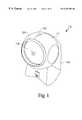
- FIG. 1is a perspective view of a presentation bar code symbol scanner 10 having an omnidirectional laser scanning platform mounted in the head portion of a multi-purpose hand-supportable/free-standing housing according to one embodiment of the present invention.
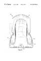
- FIG. 2is a rear view of the presentation bar code symbol scanner 10 of FIG. 1 .
- FIG. 3is a side view of a circular housing bumper 20 .
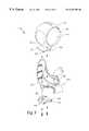
- FIG. 4is an exploded perspective view of the scanner 10 of in FIGS. 1-3.
- FIG. 5is an exploded perspective view of the scanner 10 showing a cross-sectional view of the base unit 60 .
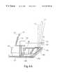
- FIG. 6is a side cross-sectional view of the scanning head 12 showing the internal component layout.
- FIG. 6Ais side view of the optical bench 34 of FIG. 6 showing the optical bench layout.
- FIG. 7is a front view of one embodiment of the scanner 10 showing the internal optical layout.
- FIG. 8is a front view of a second embodiment of the scanner 10 showing the internal optical layout.
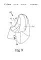
- FIG. 9is a perspective view of base unit 60 .
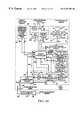
- FIG. 10is a schematic block diagram of first exemplary embodiment of the automatically-activated scanning system of the present invention.
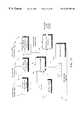
- FIG. 10Ais a schematic representation of second embodiment of an automatically-activated scanning system of the present invention.
- FIG. 11is a schematic representation of third embodiment of the automatically-activated scanning system of the present invention.
- FIG. 11Ais a schematic representation of a fourth embodiment of the automatically-activated scanning system of the present invention.
- FIG. 12is a top view of guide plate 40 of FIGS. 4 and 5.
- FIG. 13is a side view of the guide plate 40 of FIG. 12 .
- FIG. 14is a side view of a slide rail 70 of FIG. 5 .
- FIG. 15is a top view of the slide rail 70 of FIG. 14 .
- FIG. 16is a front view of the slide rail 70 of FIGS. 14 and 15.
- FIG. 17is a perspective view of the optical bench 34 of FIGS. 6 and 6A stripped of optical components.
- FIG. 17Ais a top view of the light collecting mirror 33 .
- FIG. 18is a side view of the optical bench 34 of FIG. 17 .
- FIG. 19is a front view of the scanner 10 showing the omnidirectional scanning pattern at the face of the unit.
- FIG. 20is a front view of the scanner 10 showing the omnidirectional scanning pattern at 2.5 inches away from the face of the unit.
- FIG. 1is a perspective view of a portable bar code scanner 10 incorporating an omnidirectional laser scanning platform according to one embodiment of the present invention.
- the scanner 10generally includes a scanning head 12 that is rotationally connected to a base unit 60 .
- the scanning head 12houses all associated optical components of the omnidirectional laser scanning platform as will be described in detail hereinafter.
- FIGS. 1 through 4show the general construction of the scanner housing.
- the scanning head 12has an aperture 11 through which an omnidirectional scanning pattern is projected.
- the scanning head 12is formed in a generally spherical configuration with a flat front window 14 and top-mounted LED power and good read indicator 50 .
- the head unit 12is preferably molded of hard plastic or the like, and can be formed in two half-sections with tongue-and-groove edges for an interlocking fit.
- the scanning window 14is generally round in configuration and mounted in a circular housing bumper 20 , which is in turn mounted in the aperture 11 in the scanning head 12 . As shown in FIG. 3, the window 14 is seated at an angle within a groove (not shown) formed in the housing bumper 20 .
- the housing bumper 20has a beveled outer lip 26 and an inner lip 24 with a channel 25 formed therebetween.
- the channel 25engages the inner edge of the aperture 11 of the scanning head 12 .
- the housing bumperhas a pair of locking rib members 23 which further engage a corresponding protrusion 21 on the interior of the scanning head 12 . (See FIG. 6)
- the combination of the channel 25 and the locking rib members 23acts to secure the window 14 and the housing bumper 20 to scanner housing 10 .
- the housing bumper 20acts to protect the front of the scanner head 12 and to cushion the scanning window 14 against damage if the unit dropped or banged.
- the window 14is a round section of transparent acrylic-type plastic with optical filtering properties such as described in detail in U.S. Pat. No. 5,627,359 (the '359 patent being commonly owned by Metrologic Instruments, Inc. and incorporated herein by reference).
- the size and shape of the scanning window and housing bumpercan be varied from the size and shape shown without changing the performance of the scanner.
- FIG. 2is a rear view and FIG. 4 is an exploded view of the scanner 10 of FIG. 1 in which the improved ergonomics of the design are apparent.
- the base unit 60has a contoured top opening 61 for receiving a neck portion 16 of the substantially spherical scanning head 12 .
- the contour of the opening 61is curved upward to provide ergonomic support for the spherical scanning head 12 and an aesthetically pleasing scanner 10 (as was shown and claimed in Applicant's corresponding U.S. Design Pat. No. D 408,806).
- the bottom portion of the base unit 60has contoured lateral recesses 15 and 17 on opposing sides to provide thumb and finger grips as shown in FIG. 2 .
- the usercan easily grip the scanner 10 in one hand by the contoured lateral recesses 15 and 17 and lift it off of a countertop surface to scan a large or bulky item.
- FIG. 4details the component parts of the scanner housing and their assembly into the scanner 10 .
- the neck portion 16 of the scanning head 12is inserted into the contoured opening 61 in the base unit 60 .
- Base unit 60rotationally supports the head unit 12 and houses a printed circuit board (“PC board”) which includes circuitry and electronics related to the functions digitizing, decoding, formatting and transmitting bar code symbol character data produced in the scanning head 12 .
- PC boardprinted circuit board
- Other related circuitry which cannot be supported in the scanning head 12can also be located on the PC mounted in the base unit 60 .
- the scanning head 12can easily be pivoted about a horizontal axis with respect to the base 60 allowing a user to position the scanning window 14 and therefore the projected scan pattern in a plurality of directions.
- the neck portion 16once inserted into base unit 60 , rests atop two opposing guide-rails 70 mounted on the interior side walls of base unit 60 .
- the guide rails 70snap fit onto correspondingly-shaped protrusions 71 formed in the interior side walls of base unit 60 .
- the guide rails 70are formed of smooth plastic and provide direct support and cushioning for the scanning head 12 .
- the underside of neck 16has a pair of arcuate indentations 22 on opposite sides of the neck.
- the guide rails 70are curved to conform to the indentations 22 on the underside of neck 16 and in general to the spherical outer surface of the scanning head 12 .
- FIGS. 14, 15 and 16are a side view, top view and front view, respectively, of the right-side guide rail 70 which is exemplary of both guide rails.
- Guide rail 70is an arcuate bracket that snap fits onto a correspondingly-curved protrusion 71 formed on the interior side walls of the scanning head 12 via a groove 77 formed along the bottom edge of the guide rail.
- Each guide rail 70has a planar side-wall portion 72 , a front spacer bracket 78 , a reinforcing rib 76 , and an arcuate slide rail 74 protruding laterally from the bottom edge of each side-wall portion 72 .
- Slide rail 74is the exterior of groove 77 . Once the groove 77 has been fitted to protrusion 71 , slide rail 74 extends into the center of the base unit 60 .
- the guide rails 70When the guide rails 70 are attached to the interior of the base unit 60 , opposite each other, they provide slidable support for the neck portion 16 and the scanning head.
- the indentations 22 formed in the side of neck portion 16rest on slide rails 74 .
- the exterior spherical surface 27 of the scanning head 12rests on the upper edge of the side-wall portion 72 of guide rails 70 .
- scanning head 12is rotated about a horizontal axis, the indentations 22 in neck 16 slide against the slide rails 74 of the guide rails 70 .
- the front spacer bracket 78 and reinforcing rib 76further act to support, position and cushion the scanning head 12 on the base unit 60 .
- a guide plate 40attaches to the underside of neck portion 16 , and guide plate 40 traverses the opposing guide rails 70 to moveably connect the scanning head 12 to the base unit 60 , thereby pivotally securing the scanning head 12 to the base unit 60 .
- FIGS. 12 and 13are a top view and a side view, respectively, of guide plate 40 .
- Guide plate 40is a substantially rectangular panel that has a pair of parallel tabs 42 and 48 , front and back, that fit within corresponding notches 43 on the underside of neck 16 to position the guide plate 40 , and two screw holes 45 to facilitate screw attachment to neck 16 . Openings 46 and 47 allow for the pass through of electrical connections.
- the guide plate 40similarly slides against underside of slide rails 74 identical to the movement of the underside of the neck 16 against the top side of slide rails 74 .
- the guide rails 70provide both lateral and elevational support for the scanning head 12 . This support by the guide rails 70 prevents the outside of the scanning head 12 from constantly brushing against the curved opening 61 of the base unit 60 , which in turn keeps the outside surface of the scanning head 12 from being scratched by the repetitive motion of rotating the head 12 with respect to the base 60 .
- FIG. 9is a perspective view of base unit 60 with guide rails 70 installed therein.
- the curved configuration of the guide rails 70 and the opening 61provides a first pivot point of radius r 1 extending from the contoured opening 61 of base unit 60 about the horizontal axis of head unit 12 , and a second pivot point of radius r 2 extending from the guide rails 70 to the same horizontal axis of head unit 12 .
- This dual-radius orbiting support configurationresults in an extremely rugged and durable scanning unit in which the scanning head 12 pivots easily about a horizontal axis with little or no friction against the base unit 12 .
- the base unit 60When used as a fixed scanner, the base unit 60 provides a well-balanced, stable and protected foundation for head unit 12 , and yet very little counter space is needed.
- a bottom plate 80is a substantially planar member that attaches to the underside of base unit 60 by four screws through screw holes 82 , thereby sealing it off. Rubber feet can be secured to the underside of bottom plate 80 to cover the screw heads and to improve the footing of the scanner. Additional screw holes 84 may be provided as desired to allow for mounting the scanner in a fixed manner to a countertop, wall or other fixed position.
- a collar 86protrudes upwardly from bottom plate 80 and fits into an opening provided in the base unit 60 .
- the collar 86has an opening 62 for the insertion of a power or communication cable.
- the bottom plate 80 and collar 86are configured to fit flush with the bottom of base unit 60 with the collar 86 fitting snugly into opening 62 . This configuration aids assembly and reinforces collar 86 to provide a rugged passage for electrical cabling.
- the bottom plate 80additionally provides support for a second PC board (not shown) which holds circuitry for digitizing, decoding, formatting and transmitting bar code symbol character data. Cabling also connects an analog signal processing board 52 (to be described) that is mounted in the scanner head 12 to a signal decoding board in the base unit 60 .
- the cablesare passed through openings formed in the neck portion 16 of the scanning head 12 and the guide plate 40 .
- the compact housing configuration described aboveyields a convenient, durable and ergonomic scanner package having a scanning head 12 that can be tilted vertically about a 30° angle with respect to the base unit 60 .
- the scanneris structurally capable of an aggressive omnidirectional scan from a free-standing fixed position atop a counter or while handheld by a user.
- the flexibility of the housing as described aboveis matched by an aggressive and reliable omnidirectional laser scanning platform.
- the scanning platform inclusive of all associated optical and electrical componentsis mounted in the head unit 12 and projects a pattern of scan lines through front window 14 onto a bar code to be read.
- FIGS. 19 and 20show the omnidirectional scanning pattern 13 as it is projected at the light transmission window 14 and 2.5 inches from the window 14 of the scanner 10 .
- the omnidirectional laser scanning platform of the present inventiongenerally employs an optical layout that is substantially similar to the optical layout taught in U.S. Pat. Nos. 5,637,852 and 5,844,227, that are incorporated by reference herein. As shown in FIGS. 6, 6 A and 7 an exemplary laser scanning platform according to the present invention is mounted within the head portion 12 of the scanner housing 10 .
- the laser scanning platformincludes an assembly of subcomponents assembled upon an optical bench 34 with respect to a central longitudinal reference plane.
- the subcomponents assemblyincludes: a scanning polygon 36 having four light reflective surfaces 36 A, 36 B, 36 C and 36 D, each disposed at a tilt angle with respect to the rotational axis of the polygon; an electrical motor 37 mounted on the optical bench and having a rotatable shaft on which polygon 36 is mounted for rotational movement therewith; an array of stationary mirrors 38 A, 38 B, 38 C, 38 D and 38 E fixedly mounted with respect to the optical bench; a laser beam production module 39 , fixedly mounted above the rotating polygon 36 for producing a laser beam having a circularized beam cross-section, and essentially free of astigmatism along its length of propagation; an analog signal processing board 52 fixedly over the rotatable polygon 36 and carrying a photodetector 51 for detecting reflected laser light and producing an analog signal, and signal processing control circuits 53 for performing various functions, including analog scan data signal processing; a light collecting mirror 33 , disposed above the array of stationary mirrors 38 for collecting light rays reflected off the rotating poly
- the laser beam production module of the present inventioncould be accomplished by employing a system of a lens and aperture as is well known in the art, a system which employs a plurality of diffractive optical elements (DOEs) for modifying the size and shape of the laser beam.
- DOEsdiffractive optical elements
- Various embodiments of DOE-based laser beam production modulesare shown and described in co-pending application Ser. No. 09/071,512 filed on May 1, 1998, commonly owned by the applicant hereof and incorporated by reference herein.
- the optical bench 34is shown in greater detail, with the polygon 36 , scanning motor 37 , laser beam production module 39 , collector mirror 33 , and stationary mirror elements 38 A through 38 E removed for illustration purposes.
- stationary mirror brackets 44 A through 44 Eare formed integral to the optical bench 34 for Mounting the stationary mirrors thereon.
- FIG. 17Ais a top view of the light collecting mirror 33 .
- the collector mirror 33attaches to a collector bracket 35 by means of a pair of integrally-formed pivot arms 31 with distal hubs 29 .
- the pivot arms 31 of collector mirror 33snap fit into notches 30 formed in collector mirror bracket 35 , and hubs 29 maintain the pivotal seating.
- the beam directing surface 32 which is mounted to the collector mirror 33must be aligned with the laser beam that is produced by the laser beam production module 39 during the manufacturing calibration process.
- the collector mirror 33must also be aligned for the efficient collection of returned light.
- the pivoting collector mirror 33allows for easy and infinite adjustment of the collector mirror 33 , and thus the beam directing surface 32 , along the vertical direction during manufacturing.
- the snug fit between the bracket notches 30 and the pivot arms 31 of the mirrorallows for an assembler to adjust the position of the mirror while preventing further unintentional movement of the mirror after the alignment is complete.
- the collector mirror 33is mounted for dual-axis adjustment. This is accomplished by mounting the collector mirror 33 in a rectangular mirror frame (not shown) with pivot points at top and bottom.
- the collector mirror frameitself has additional pivot arms on the sides for fitting into the notches 30 of mirror bracket 35 (similar to the pivot arms shown integral to mirror 33 in FIG. 17 A).
- This combination of pivot points both at the top and bottom of the mirror and on the sides of the mirror frameprovides for adjustment of the mirror in both a right-to-left direction as well as the up-and-down direction provided for in the scanner embodiment detailed above.
- the pivoting collector mirror 33can be adjusted and calibrated at the factory. If desired, the pivot points of the collector mirror 33 can be fixed by gluing after calibration.
- the laser beam module support bench 41is formed at a height above the mirror bracket array 44 . This allows for mounting of the polygon 36 and rotating motor 37 below the laser beam production module 39 .
- the laser beam production module 39is mounted in the laser module mount bracket 28 .
- the analog signal processing board 52attaches to PC board bracket 54 , above and behind the laser module mount bracket 28 .
- the entire optical bench 34is a single piece molded plastic unit, which holds all of the components that make up the omnidirectional laser scanning platform.
- the collector mirror 33 , beam directing surface 32 , laser beam production module 39 and photodetector 51are mounted above the polygon 36 and mirror array 38 .
- a laser beamis produced from the laser beam production module 39 and is directed towards the beam directing surface 32 mounted on the light collector mirror 33 .
- the laser beamreflects from the beam directing surface 32 towards the mirrored facets on the rotating scanning polygon 36 .
- the incident laser beamreflects off the rotating mirrors 36 A through 36 D and sweeps the laser beam about its rotational axis along a plurality of different paths which intersect the stationary array of mirrors 38 A through 38 E on the optical bench 34 .
- the laser beamreflects off the rotating mirrors and is repeatedly swept across the array of stationary mirrors thereby producing first, second, third, fourth and fifth groups of plural scan lines, respectively.
- Each scan line in each group of scan linesis substantially parallel to each other scan line in that group of scan lines.
- the intersection of the groups of parallel scan linesproduces a highly collimated canning pattern.
- the scan lines that make up this highly collimated scanning pattern 13are projected out through the light transmission window and intersect about a projection axis that extends outward from the light transmission window 14 to produce a highly confined narrow scanning volume.
- a bar code symbolcan be scanned omnidirectionally, while preventing unintentional scanning of code symbols on objects located outside of the scanning volume.
- the bar code symbolWhen a bar code symbol on an object is presented to the highly collimated scanning pattern 13 projected through a narrowly confined scanning volume the bar code symbol is scanned independent of its orientation in the scanning volume. At least a portion of the laser light reflected from the scanned code symbol is directed through the light transmission window 14 , reflected off the stationary array of mirrors 38 , reflected off the rotating polygon 36 , focused by the light collection mirror 33 onto the photodetector 51 , whereupon an electrical signal is produced for use in decode signal processing.
- the omnidirectional laser scanning platform of the present inventioncan be automatically activated or can include manual activation means.
- Manual activation meanscan include a trigger or other switch located on the exterior of the scanner housing which when depressed activates the laser, the laser scanning mechanism, the photoreceiving circuitry and decoding circuitry.
- Laser bar code scanning systems employing manual activation meansare well known in the art.
- Various embodiments of automatically-activated bar code symbol scanning systemsare detailed in FIGS. 10, 10 A, 11 and 11 A. A number of the subsystems are common to all embodiments and are thus described in detail with respect to FIG. 10 only. However, the description of these subsystems applies similarly when they are included in the other listed embodiments.
- an automatically activated bar code symbol scanning system of the first designis composed of a number of subsystems, an infrared (IR) based object detection subsystem 112 as taught in prior U.S. Pat. Nos. 5,260,553, 5,340,971 and 5,808,285, incorporated herein by reference; a scanning means 111 , a photoreceiving circuit 112 , analog-to-digital conversion circuit 113 , a bar code presence detection subsystem 114 as taught in prior U.S. Pat. Nos.
- IRinfrared
- bar code scan range detection module 115symbol decoding module 116 , data format conversion module 117 , symbol character data storage unit 118 , and a data transmission circuit 119 .
- these componentsare operably associated with a programmable system controller 122 which provides a great degree of versatility in system control, capability and operation.
- the purpose of the object detection subsystemis to perform the following primary functions during object detection: (i) automatically and synchronously transmitting and receiving pulse infrared (IR) signals within an IR-based object detection field; (ii) automatically detecting an object in at least a portion of the IR-based object field by analysis of the received IR pulse signals; and (iii) in response thereto, automatically generating a first control activation signal A 1 indicative of such automatic detection of the object within the object detection field.
- the first control activation signal A 1is provided to the system control subsystem 122 for detection, analysis and programmed response.
- the scanning circuit 111includes, a light source 147 which is shown as a solid state visible laser diode (VLD), but can be any source of intense light suitably selected for maximizing the reflectivity from the object's surface bearing a bar code symbol, a scanning mechanism 150 such as a rotating polygon which is mounted on a rotating motor driven by motor drive 151 .
- VLDsolid state visible laser diode
- the system controllerTo selectively activate the laser light source 147 and scanning mechanism 150 , upon receiving control activation signal A 1 , the system controller provides laser diode enable signal E L scanning mechanism enable signal E M as input to driver circuits 148 and 151 respectively.
- signals E L and E Mare at a logical high level the VLD is activated and the beam is scanned through the light transmission aperture and across the scan field.
- Photoreceiving circuit 112is provided for the purpose of detecting at least a portion of laser light of variable intensity, which is reflected off the object and bar code symbol within the scan field. Upon detection of this scan data signal, photoreceiving circuit 112 produces an analog scan data signal D 1 indicative of the detected light intensity. Analog scan data signal D 1 is provided as input to A/D conversion circuit 113 .
- A/D conversion circuit 113processes analog scan data signal D 1 to provide a digital scan data signal D 2 which resembles, in form, a pulse width modulated signal, where logical “1” signal levels represent spaces of the scanned bar code symbol and logical “0” signal levels represent bars of the scanned bar code symbol.
- A/D conversion circuit 113can be realized by any conventional A/D chip. Digitized scan data signal D 2 is provided as input to bar code presence detection module 114 and symbol decoding module 116 .
- the purpose and function of the bar code presence detection moduleis to determine whether a bar code is present or absent from the scan field over a time interval specified by the system controller, by detecting a bar code symbol “envelop” from digital scan data signal D 2 by analyzing the digital count and sign data in the signal.
- the bar code presence detection moduleprovides signal A 2 to the system controller 122 which then causes the system to undergo a transition for the bar code presence detection state to the bar code reading state.
- the system controller 122Upon receiving control activation signal A 3 , the system controller 122 generates and provides enable signals E FC , E DS , and E DT to the data format conversion module 117 , data storage unit 118 , and data transmission circuit 119 , respectively at particular stages of its control program.
- Symbol decoding module 116provides decoded symbol character data D 3 to data format module 117 to convert data D 3 into two differently formatted types of symbol character data, namely D 4 and D 5 .
- Format-converted symbol character data D 4is of the “packed data” format, particularly adapted for efficient storage in the data storage unit 118 .
- Format-converted symbol character data D 5is particularly adapted for data transmission to data collection and storage device, or a host device such as a computer or electronic cash register.
- format converted data D 5When format converted data D 5 is to be transmitted to a host device, the system controller 122 will generate and provide enable signal E DT to data transmission circuit 119 . Thereupon, data transmission circuit 119 transmits format-converted data D 5 to the data collection or host device via the data transmission lines of flexible connector cable 125 .
- a second embodiment of an automatically activated bar code symbol scanning system of a second designis composed of a number of subsystems as well, namely an IR-based object detection subsystem 82 ; a laser-based bar code symbol detection subsystem 83 ; a laser-based bar code symbol reading subsystem 84 ; a data transmission subsystem 85 ; a state indication subsystem 86 ; a data transmission activation switch or control device 87 A integrated with the scanner housing in part or whole; a mode-selection sensor 87 B integrated with the scanner housing in part or whole; and a system control subsystem 88 operably connected to the other subsystems described above.
- system 79has a number of preprogrammed operational states, namely: an object detection state; a bar code symbol detection state; a bar code symbol reading state; and a data transmission state.
- the IR-based object detection subsystem 82performs the following primary functions during the object detection state: (i) automatically and synchronously transmitting and receiving pulse infrared (IR) signals within an IR-based object detection field 89 defined relative to the scanner housing 10 ; (ii) automatically detecting an object in a least a portion of the IR-based object detection field 89 by analysis of the received IR pulse signals; and (iii) in response thereto, automatically generating a first control activation signal A 1 indicative of such automatic detection of the object within the object detection field.
- object detection, bar code detection and bar code reading fields 89 , 90 and 91have been schematically represented only general terms. For purposes of clarity, the specific characteristics of these fields have not been shown. Notably, however, such characteristics can be ascertained from the various references relating thereto which are identified and incorporated herein by reference.
- FIG. 10Athe laser-based bar code symbol detection subsystem 83 performs the following primary functions during the bar code symbol detection state: (i) automatically generating a visible laser scanning pattern of predetermined characteristics within the laser-based bar code (symbol) detection field 90 , defined relative to the scanner housing (not shown), to enable scanning of a bar code symbol on the detected object; (ii) automatically processing scan data collected from the bar code symbol detection field
- the second control activation signal A 2is provided to the system control subsystem 88 for detection, analysis and programmed response.
- second control activation signal A 2is provided to the system control subsystem 88 , this causes the bar code symbol reading device to undergo a state transition from bar code symbol detection state to bar code symbol reading state. This transition has also been described in detail in connection with FIG. 10 above.
- FIG. 10Athe laser-based bar code symbol reading subsystem 84 performs the following functions during the bar code symbol reading state: (i) automatically generating an omnidirectional visible laser scanning pattern within the laser-based bar code symbol reading field 91 defined relative to the scanner housing, to enable scanning of the detected bar code symbol therein; (ii) automatically decode-processing scan data collected from the bar code symbol reading field 91 so as to detect the
- the third control activation signal A 3is provided to the system control subsystem 88 for detection, analysis and programmed response.
- the system control subsystem 88responds as described above in relation to FIG. 10, whereby the data is decoded and formatted and sent to the data transmission subsystem 85 .
- the state-selection sensor 87 Beffectively overrides the data transmission switch 87 A.
- the data transmission switch 87 Aeffectively overrides the state-selection sensor 87 B.
- the system control subsystem 88performs the following primary functions: (i) automatically receiving control activation signals A 1 , A 2 , A 3 and A 4 ; (ii) automatically generating enable signals E 1 , E 2 , E 3 , and E 4 ; and (iii) automatically controlling the operation of the other subsystems in accordance with a system control program carried out by the system control subsystem 88 during the various modes of system operation.
- FIGS. 11 and 11Aillustrate an automatically-activated laser bar code scanning system wherein there is no object detection subsystem and the system is activated from the bar code presence detection state.
- the automatically-activated laser bar code scanning system conceptis shown in related application Ser. No. 09 / 204 , 176 (the '176 application being commonly owned by Metrologic Instruments, Inc. and incorporated herein by reference). As indicated in FIG.
- the automatically-activated bar code symbol scanning platform of this third general system design 100comprises a number of subsystems, namely: a laser-based bar code symbol detection subsystem 101 ; a laser-based bar code symbol reading subsystem 102 ; a data transmission subsystem 103 ; a state indication subsystem 104 ; a data transmission activation switch or control device 105 A integrated with the scanner housing (not shown) in part or whole; a mode-selection sensor 105 B integrated with the scanner housing in part or whole; and a system control subsystem 106 operably connected to the other subsystems described above.
- the system 100has a number of preprogrammed states of operation, namely: an object detection state; a bar code symbol detection state; a bar code symbol reading state; and a data transmission state.
- the second control activation signal A 2is provided to the system control subsystem 106 for detection, analysis and programmed response.
- second control activation signal A 2is provided to the system control subsystem 88 , this causes the bar code symbol reading device to undergo a state transition from bar code symbol detection state to bar code symbol reading state. This transition has been previously described in detail in connection with FIG. 10 above.
- the third control activation signal A 3is provided to the system control subsystem 106 for detection, analysis and programmed response.
- the system control subsystem 106responds as described above in relation to FIG. 10, whereby the data is decoded and formatted and sent to the data transmission subsystem 103 .
- the mode-select sensor 105 Beffectively overrides the data transmission switch 105 A.
- the data transmission switch 105 Aeffectively overrides the mode-select sensor 105 B.
- system control subsystem 106performs the following primary functions: (i) automatically receiving control activation signals A 2 , A 3 and A 4 ; (ii) automatically generating enable signals E 2 , E 3 , and E 4 ; and (iii) automatically controlling the operation of the other subsystems in accordance with a system control program carried out by the system control subsystem 106 during the various modes of system operation.
- the fourth general system design of the automatically-activated bar code symbol scanning as shown in FIG. 11Acomprises a number of subsystems, namely: a laser-based bar code symbol detection subsystem 131 ; a laser-based bar code symbol reading subsystem 132 ; a data transmission subsystem 133 ; a state indication subsystem 134 ; and a system control subsystem 136 operably connected to the other subsystems described above.
- the system 130has a number of preprogrammed states of operation, namely: a bar code symbol detection state; a bar code symbol reading state; and a data transmission state.
- the second control activation signal A 2is provided to the system control subsystem 136 for detection, analysis and programmed response.
- second control activation signal A 2is provided to the system control subsystem 136 , this causes the bar code symbol reading device to undergo a state transition from bar code symbol detection state to bar code symbol reading state. This transition has been described in detail in connection with FIG. 10 above.
- the third control activation signal A 3is provided to the system control subsystem 136 for detection, analysis and programmed response.
- the system control subsystem 136responds as described above in relation to FIG. 10, whereby the data is decoded and formatted and sent to the data transmission subsystem 133 .
- the system control subsystem 136performs the following primary functions: (i) automatically receiving control activation signals A 2 , A 3 and A 4 ; (ii) automatically generating enable signals E 2 , E 3 , and E 4 ; and (iii) automatically controlling the operation of the other subsystems in accordance with a system control program carried out by the system control subsystem 106 during the various modes of system operation.
Landscapes
- Physics & Mathematics (AREA)
- Engineering & Computer Science (AREA)
- Electromagnetism (AREA)
- General Physics & Mathematics (AREA)
- Theoretical Computer Science (AREA)
- Toxicology (AREA)
- Artificial Intelligence (AREA)
- Computer Vision & Pattern Recognition (AREA)
- General Health & Medical Sciences (AREA)
- Health & Medical Sciences (AREA)
- Optics & Photonics (AREA)
- Mechanical Engineering (AREA)
- General Engineering & Computer Science (AREA)
- Life Sciences & Earth Sciences (AREA)
- Geology (AREA)
- Structural Engineering (AREA)
- Mechanical Optical Scanning Systems (AREA)
Abstract
Description
Claims (26)
Priority Applications (3)
| Application Number | Priority Date | Filing Date | Title |
|---|---|---|---|
| US09/323,292US6257492B1 (en) | 1990-09-10 | 1999-06-01 | Combination hand-held and counter-top omni-directional scanner |
| US09/900,005US6651890B2 (en) | 1990-09-10 | 2001-07-06 | Combination hand-held and counter-top omnidirectional scanner |
| US10/928,907US7624924B2 (en) | 1990-09-10 | 2004-08-27 | Hand-held compact ergonomic laser scanner with integrated scanner activation or data transmission switch in scanner housing |
Applications Claiming Priority (22)
| Application Number | Priority Date | Filing Date | Title |
|---|---|---|---|
| US07/580,738US5216232A (en) | 1990-09-10 | 1990-09-10 | Projection laser scanner producing a narrow scan volume |
| US3631493A | 1993-03-24 | 1993-03-24 | |
| US08/278,109US5484992A (en) | 1990-09-17 | 1993-11-24 | Automatic hand-supportable laser scanner with flickering laser scanning beam to improve visibility thereof and beam-symbol alignment during bar code symbol presence detection |
| US08/292,237US5808285A (en) | 1990-09-17 | 1994-08-17 | Portable code symbol reading device with one-way wireless data packet transmission link to base unit employing condition-dependent acoustical signalling for data packet reception acknowledgement |
| US08/293,493US5525789A (en) | 1990-09-17 | 1994-08-19 | Automatic laser bar code symbol reading system and method of reading bar code symbols using same |
| US08/365,193US5557093A (en) | 1990-09-10 | 1994-12-28 | Compact projection laser scanner for producing a narrowly confined scanning volume for omni-directional scanning of code symbols therein, while preventing unintentional scanning of code symbols on nearby objects |
| US08/439,224US5627359A (en) | 1991-09-17 | 1995-05-11 | Laser code symbol scanner employing optical filtering system having narrow band-pass characteristics and spatially separated optical filter elements with laser light collection optics arranged along laser light return path disposed therebetween |
| US08/475,376US5637852A (en) | 1990-09-10 | 1995-06-07 | Counter-top projection laser scanner for omni-directional scanning of code symbols within a narrowly confined scanning volume, while preventing unintentional scanning of code symbols of nearby objects |
| US08/476,069US5591953A (en) | 1990-09-17 | 1995-06-07 | Countertop bar code symbol reading system having automatic hand-supportable bar code symbol reading device and stand for supporting projected scan field thereof |
| US48930595A | 1995-06-09 | 1995-06-09 | |
| US08/561,479US5661292A (en) | 1990-09-17 | 1995-11-20 | Automatic laser projection scanner with improved laser beam scanning efficiency |
| US57394995A | 1995-12-18 | 1995-12-18 | |
| US08/584,135US5616908A (en) | 1991-09-17 | 1996-01-11 | Automatic countertop laser scanner with flickering laser scanner beam for improved visibility thereof during bar code symbol reading |
| US08/615,054US6286760B1 (en) | 1994-08-17 | 1996-03-12 | Automatic hand-supportable laser projection scanner for omni-directional reading of bar code symbols within a narrowly confined scanning volume |
| US08/645,335US5942743A (en) | 1994-08-17 | 1996-05-13 | Portable automatic hand-supportable omnidirectional laser projection scanner with power conserving control system |
| US08/645,331US5844227A (en) | 1993-11-24 | 1996-05-13 | Automatic hand-supportable omnidirectional laser projection scanner with scan-head directed projection axis for intuitive hand-supported omnidirectional scanning of bar code symbols within a narrowly confined scanning volume extending thereabout |
| US08/645,486US5796091A (en) | 1993-11-24 | 1996-05-13 | Automatic hand-supportable omnidirectional laser projection scanner with handle-controllable projection axis |
| US08/827,118US5925870A (en) | 1990-09-17 | 1997-03-27 | Automatic hand-supportable laser bar code symbol scanning device and method of scanning bar codes using same |
| US85029597A | 1997-05-05 | 1997-05-05 | |
| US08/865,257US6460767B1 (en) | 1990-09-10 | 1997-05-29 | Optical scanner for omni-directional scanning of code symbols within a scanning volume |
| US09/204,176US6283375B1 (en) | 1990-09-10 | 1998-12-03 | Automatically-activated hand-supportable laser scanning bar code symbol reading system with data transmission activation switch |
| US09/323,292US6257492B1 (en) | 1990-09-10 | 1999-06-01 | Combination hand-held and counter-top omni-directional scanner |
Related Parent Applications (9)
| Application Number | Title | Priority Date | Filing Date |
|---|---|---|---|
| US08/645,331Continuation-In-PartUS5844227A (en) | 1990-09-10 | 1996-05-13 | Automatic hand-supportable omnidirectional laser projection scanner with scan-head directed projection axis for intuitive hand-supported omnidirectional scanning of bar code symbols within a narrowly confined scanning volume extending thereabout |
| US08/645,335Continuation-In-PartUS5942743A (en) | 1990-09-10 | 1996-05-13 | Portable automatic hand-supportable omnidirectional laser projection scanner with power conserving control system |
| US08/827,118Continuation-In-PartUS5925870A (en) | 1990-09-10 | 1997-03-27 | Automatic hand-supportable laser bar code symbol scanning device and method of scanning bar codes using same |
| US08/847,580Continuation-In-PartUS5789731A (en) | 1990-09-10 | 1997-04-24 | Laser code symbol scanner employing optical filtering system having narrow pass-band characteristics and spatially-separated optical filter elements with laser light collection optics arranged along laser light return path disposed therebetween |
| US85029597AContinuation-In-Part | 1990-09-10 | 1997-05-05 | |
| US08/865,257Continuation-In-PartUS6460767B1 (en) | 1990-09-10 | 1997-05-29 | Optical scanner for omni-directional scanning of code symbols within a scanning volume |
| US08/943,267Continuation-In-PartUS6098885A (en) | 1990-09-10 | 1997-10-03 | Countertop projection laser scanning system for omnidirectional scanning volume projected above a countertop surface of code symbols within a narrowly-confined scanning |
| US08/943,627Continuation-In-PartUS5979605A (en) | 1996-10-23 | 1997-10-03 | Adjustable vehicle service area and service walkway |
| US09/204,176Continuation-In-PartUS6283375B1 (en) | 1990-09-10 | 1998-12-03 | Automatically-activated hand-supportable laser scanning bar code symbol reading system with data transmission activation switch |
Related Child Applications (6)
| Application Number | Title | Priority Date | Filing Date |
|---|---|---|---|
| US3631493AContinuation | 1990-09-10 | 1993-03-24 | |
| US08/293,493Continuation-In-PartUS5525789A (en) | 1990-09-10 | 1994-08-19 | Automatic laser bar code symbol reading system and method of reading bar code symbols using same |
| US08/827,118ContinuationUS5925870A (en) | 1990-09-10 | 1997-03-27 | Automatic hand-supportable laser bar code symbol scanning device and method of scanning bar codes using same |
| US85029597AContinuation | 1990-09-10 | 1997-05-05 | |
| US09/900,005ContinuationUS6651890B2 (en) | 1990-09-10 | 2001-07-06 | Combination hand-held and counter-top omnidirectional scanner |
| US10/104,641ContinuationUS20020100804A1 (en) | 1990-09-10 | 2002-03-22 | Hand-held compact ergonomic laser scanner with integrated scanner activation or data transmission switch in scanner housing |
Publications (1)
| Publication Number | Publication Date |
|---|---|
| US6257492B1true US6257492B1 (en) | 2001-07-10 |
Family
ID=27586619
Family Applications (1)
| Application Number | Title | Priority Date | Filing Date |
|---|---|---|---|
| US09/323,292Expired - Fee RelatedUS6257492B1 (en) | 1990-09-10 | 1999-06-01 | Combination hand-held and counter-top omni-directional scanner |
Country Status (1)
| Country | Link |
|---|---|
| US (1) | US6257492B1 (en) |
Cited By (22)
| Publication number | Priority date | Publication date | Assignee | Title |
|---|---|---|---|---|
| US20020104886A1 (en)* | 1998-12-03 | 2002-08-08 | Metrologic Instruments, Inc. | Automatically-activated hand-supportable laser scanning bar code symbol reading system with omnidirectional and unidirectional scanning modes in addition to a data transmission activation switch |
| WO2003023691A1 (en)* | 2001-09-12 | 2003-03-20 | Psc Scanning, Inc. | Optical scanning system and integrated optics module therefor |
| US20030222146A1 (en)* | 1998-12-03 | 2003-12-04 | Metrologic Instruments, Inc. | Automatically-activated hand-supportable multi-mode laser scanning bar code symbol reading system |
| USD486827S1 (en) | 2002-10-25 | 2004-02-17 | Gempsy France | Price verifier employing scanner |
| US6719201B2 (en) | 1996-01-31 | 2004-04-13 | Psc Scanning, Inc. | Multiple aperture data reader for multi-mode operation |
| US20040173684A1 (en)* | 1998-12-03 | 2004-09-09 | Metrologic Instruments, Inc. | Automatically-activated hand-supportable omni-directional laser scanning bar code symbol reader having a user-selectable linear scanning menu-reading mode supported by a stroboscopically-pulsed omni-directional laser scanning pattern for improved bar code symbol navigation and alignment during menu-reading operations |
| US20050150959A1 (en)* | 2004-01-09 | 2005-07-14 | John Izzo | Optical reader |
| US7073718B2 (en)* | 1999-06-07 | 2006-07-11 | Metrologic Instruments, Inc. | Planar laser illumination and imaging (PLIIM) systems employing laser-diode based planar laser illumination arrays and linear electronic image detection arrays |
| US20070284441A1 (en)* | 2006-06-13 | 2007-12-13 | Joseph Walczyk | Method and apparatus for uniquely associating a bar code reading terminal to a cash register in a retail store network |
| US20080078839A1 (en)* | 2006-09-28 | 2008-04-03 | Edward Barkan | Electro-optical reader with object sensor |
| US20080318191A1 (en)* | 2004-03-25 | 2008-12-25 | Mcadams John B | Braille type device, system, and method |
| US7556203B2 (en) | 2005-06-27 | 2009-07-07 | Hand Held Products, Inc. | Method and system for linking a wireless hand held optical reader with a base unit or other wireless device |
| CN102486824A (en)* | 2010-12-02 | 2012-06-06 | 深圳迈瑞生物医疗电子股份有限公司 | Bar code scanning device and blood cell analyzer thereof |
| WO2014110285A1 (en)* | 2013-01-11 | 2014-07-17 | Datalogic ADC, Inc. | Adjustable data reader with pivot mount |
| USD734337S1 (en)* | 2014-04-01 | 2015-07-14 | Datalogic Ip Tech S.R.L. | Coded information reader |
| US20160229501A1 (en)* | 2015-02-10 | 2016-08-11 | Cheng-Rung Tsai | Lifesaving bag |
| CN104718552B (en)* | 2012-09-13 | 2017-11-28 | 多伦多大学理事会 | Systems and methods for counting fetal and maternal red blood cells |
| CN109325376A (en)* | 2018-06-08 | 2019-02-12 | 深圳盈达信息科技有限公司 | PDA with rotatable scanning head |
| US10380392B2 (en) | 2016-06-14 | 2019-08-13 | Datalogic IP Tech, S.r.l. | Variable orientation scan engine |
| USD859411S1 (en)* | 2016-08-01 | 2019-09-10 | Hand Held Products, Inc. | Optical scanner |
| US20200380218A1 (en)* | 2019-06-03 | 2020-12-03 | Zebra Technologies Corporation | Digital Barcode Reader |
| CN113536819A (en)* | 2021-07-09 | 2021-10-22 | 杭州巨象智能物联科技有限公司 | Bar code scanner |
Citations (79)
| Publication number | Priority date | Publication date | Assignee | Title |
|---|---|---|---|---|
| US3902048A (en) | 1974-07-11 | 1975-08-26 | Ibm | Omnidirectional optomechanical scanning apparatus |
| US3911270A (en) | 1974-08-28 | 1975-10-07 | Identicon Corp | Light pen reading |
| US3919527A (en) | 1973-07-26 | 1975-11-11 | Ibm | Omnidirectional optical scanner |
| US3947816A (en) | 1974-07-01 | 1976-03-30 | International Business Machines Corporation | Omnidirectional optical scanning apparatus |
| US3978317A (en) | 1974-02-26 | 1976-08-31 | Matsushita Electric Industrial Co., Ltd. | Optical bar code reader |
| US4006343A (en) | 1973-10-23 | 1977-02-01 | Matsushita Electric Industrial Co., Ltd. | Code read-out means |
| US4026630A (en) | 1975-12-23 | 1977-05-31 | International Business Machines Corporation | Scanning apparatus using holographic beam deflector |
| US4072859A (en) | 1976-10-04 | 1978-02-07 | Recognition Equipment Incorporated | Wand turn-on control |
| US4086476A (en) | 1976-07-29 | 1978-04-25 | Ncr Corporation | Control circuit for a code reading device |
| US4093865A (en) | 1977-04-29 | 1978-06-06 | National Semiconductor Corporation | Code symbol scanner using a double X bar pattern |
| US4097729A (en) | 1975-05-27 | 1978-06-27 | Data General Corporation | Scanning system and method |
| US4136821A (en) | 1976-09-01 | 1979-01-30 | Nippondenso Co., Ltd. | Method and apparatus for recognizing code information |
| US4240064A (en) | 1978-09-11 | 1980-12-16 | Ncr Corporation | Power limiting circuit for bar code reader |
| US4387297A (en) | 1980-02-29 | 1983-06-07 | Symbol Technologies, Inc. | Portable laser scanning system and scanning methods |
| US4409470A (en) | 1982-01-25 | 1983-10-11 | Symbol Technologies, Inc. | Narrow-bodied, single-and twin-windowed portable laser scanning head for reading bar code symbols |
| US4431912A (en) | 1981-11-13 | 1984-02-14 | International Business Machines Corp. | Method for controlling the operation of an optical scanner |
| US4460120A (en) | 1982-01-25 | 1984-07-17 | Symbol Technologies, Inc. | Narrow bodied, single- and twin-windowed portable laser scanning head for reading bar code symbols |
| US4496831A (en) | 1980-02-29 | 1985-01-29 | Symbol Technologies, Inc. | Portable laser scanning system and scanning methods |
| US4521678A (en) | 1984-01-13 | 1985-06-04 | Databar Corporation | Battery-powered optical bar code reader and voltage regulator therefor |
| US4553081A (en) | 1982-06-07 | 1985-11-12 | Norand Corporation | Portable battery powered system |
| US4570057A (en) | 1981-12-28 | 1986-02-11 | Norand Corporation | Instant portable bar code reader |
| US4575625A (en) | 1983-09-27 | 1986-03-11 | Knowles Carl H | Integral hand-held laser scanner |
| US4603262A (en) | 1983-08-22 | 1986-07-29 | Optel Systems Inc. | Optical device for detecting coded symbols |
| US4639070A (en) | 1980-01-11 | 1987-01-27 | Fujitsu Limited | Beam scanning type information readout device |
| US4639606A (en) | 1984-10-26 | 1987-01-27 | Optel System Limited | Bar code scanner laser radiation exposure limit control system |
| US4647143A (en) | 1983-04-08 | 1987-03-03 | Fujitsu Limited | Light-beam scanning apparatus |
| US4652732A (en) | 1985-09-17 | 1987-03-24 | National Semiconductor Corporation | Low-profile bar code scanner |
| US4673805A (en) | 1982-01-25 | 1987-06-16 | Symbol Technologies, Inc. | Narrow-bodied, single- and twin-windowed portable scanning head for reading bar code symbols |
| US4713532A (en) | 1985-11-21 | 1987-12-15 | Metrologic Instruments, Inc. | Compact omnidirectional laser scanner |
| US4736095A (en) | 1982-01-25 | 1988-04-05 | Symbol Technologies, Inc. | Narrow-bodied, single- and twin-windowed portable laser scanning head for reading bar code symbols |
| US4737702A (en) | 1982-06-07 | 1988-04-12 | Norand Corporation | Battery charging control system particularly for hand held device |
| US4766299A (en) | 1986-03-28 | 1988-08-23 | Spectra-Physics, Inc. | Hand-mounted bar code reader |
| US4766297A (en)* | 1987-01-08 | 1988-08-23 | Recognition Equipment Incorporated | Dual mode stationary and portable scanning system |
| US4766298A (en) | 1986-11-10 | 1988-08-23 | Ncr Corporation | Low-profile portable UPC optical scanner |
| US4795224A (en) | 1986-10-06 | 1989-01-03 | Katsuchika Goto | Optical scanning pattern generator |
| US4816660A (en) | 1985-02-28 | 1989-03-28 | Symbol Technologies, Inc. | Portable laser diode scanning head |
| US4845349A (en) | 1986-09-30 | 1989-07-04 | Spectra-Physics, Inc. | Bar code scanner laser emission reduction |
| US4861973A (en) | 1987-06-18 | 1989-08-29 | Spectra-Physics, Inc. | Optical scan pattern generating arrangement for a laser scanner |
| US4877949A (en) | 1986-08-08 | 1989-10-31 | Norand Corporation | Hand-held instant bar code reader system with automated focus based on distance measurements |
| US4897532A (en) | 1985-02-28 | 1990-01-30 | Symbol Technologies, Inc. | Portable laser diode scanning head |
| US4920255A (en) | 1988-10-31 | 1990-04-24 | Stephen C. Gabeler | Automatic incremental focusing scanner system |
| US4930848A (en) | 1989-01-26 | 1990-06-05 | Metrologic Instruments, Inc. | Portable laser scanner with integral scanner engine |
| US4933538A (en) | 1988-10-21 | 1990-06-12 | Symbol Technologies, Inc. | Scanning system with adjustable light output and/or scanning angle |
| US4939356A (en) | 1989-05-02 | 1990-07-03 | Spectra-Physics, Inc. | Bar code scanner with asterisk scan pattern |
| US4960985A (en) | 1985-11-21 | 1990-10-02 | Metrologic Instruments, Inc. | Compact omnidirectional laser scanner |
| US4962980A (en) | 1989-01-23 | 1990-10-16 | Metrologic Instruments, Inc. | Laser scanner engine with folded beam path |
| US4970379A (en) | 1987-04-30 | 1990-11-13 | Norand Corporation | Bar code scanner system and scanner circuitry therefor |
| US5000529A (en) | 1989-04-20 | 1991-03-19 | Fujitsu Limited | Optical scanner |
| US5015833A (en) | 1988-10-31 | 1991-05-14 | Symbol Technologies, Inc. | Scan board module for laser scanners |
| US5017765A (en) | 1982-01-25 | 1991-05-21 | Symbol Technologies, Inc. | Hand held bar code scanner with automatic scanner deenergization |
| US5026975A (en) | 1988-03-12 | 1991-06-25 | International Business Machines Corporation | Bar code laser scanner arrangement for a cashier stand |
| US5039184A (en) | 1988-06-24 | 1991-08-13 | Fujitsu Limited | Optical beam scanner for bar-code |
| EP0448537A2 (en)* | 1990-03-20 | 1991-09-25 | Esselte Meto International GmbH | A hand scanner for reading bar codes |
| US5059777A (en) | 1989-09-21 | 1991-10-22 | Ncr Corporation | Scanning system presence sensing apparatus and method |
| US5086215A (en) | 1988-10-26 | 1992-02-04 | National Computer Systems, Inc. | Method and apparatus for discriminating or locating bar codes for an optical mark reader |
| US5092793A (en)* | 1990-04-23 | 1992-03-03 | John Stephan | Swivel apparatus providing strain relief for an electrical conductor |
| US5107100A (en) | 1988-11-17 | 1992-04-21 | Symbol Technologies, Inc. | Portable scanner with on-board keyboard, display, transceiver and printer |
| US5115333A (en) | 1990-04-16 | 1992-05-19 | Ncr Corporation | Variable laser beam attenuator |
| US5124539A (en) | 1989-06-16 | 1992-06-23 | Symbol Technologies, Inc. | Scan pattern generators for bar code symbol readers |
| US5124537A (en) | 1990-10-29 | 1992-06-23 | Omniplanar, Inc. | Omnidirectional bar code reader using virtual scan of video raster scan memory |
| US5132523A (en) | 1990-12-10 | 1992-07-21 | Ncr Corporation | Dual mode optical scanning system |
| US5153417A (en) | 1989-08-04 | 1992-10-06 | Nippondenso Co., Ltd. | Bar code reader using holograms |
| EP0520632A2 (en)* | 1991-06-24 | 1992-12-30 | Ncr International Inc. | Bar code scanner apparatus |
| US5180904A (en) | 1982-01-25 | 1993-01-19 | Symbol Technologies, Inc. | Bar code scanner with automatic de-activation of scan upon bar code recognition |
| US5196696A (en) | 1992-02-10 | 1993-03-23 | Ncr Corporation | Counter rotating optical scanning unit with Fresnel reflection filtering |
| US5212370A (en) | 1990-11-20 | 1993-05-18 | Ncr Corporation | Apparatus and method for extending laser life by discontinuous operation |
| US5216231A (en) | 1988-05-13 | 1993-06-01 | Alps Electric Co., Ltd. | Self-scanning code reading device |
| US5221832A (en) | 1991-09-13 | 1993-06-22 | Ncr Corporation | Raster variation method for omnidirectional optical scanners |
| US5250790A (en) | 1988-05-11 | 1993-10-05 | Symbol Technologies, Inc. | Hand-mounted scanner with automatic manual initiation of reading indicia |
| US5262627A (en) | 1989-10-30 | 1993-11-16 | Symbol Technologies, Inc. | Scanning arrangement and method |
| US5280162A (en) | 1991-12-23 | 1994-01-18 | Symbol Technologies, Inc. | Object sensing system for bar code laser scanners |
| US5324924A (en) | 1992-05-11 | 1994-06-28 | Symbol Technologies, Inc. | Bar code decoder with changeable working ranges |
| US5420411A (en) | 1991-06-14 | 1995-05-30 | Symbol Technologies, Inc. | Combined range laser scanner |
| US5479002A (en)* | 1988-05-11 | 1995-12-26 | Symbol Technologies, Inc. | Bar code scanner with scanning beam and/or field of view adjustable about three mutually orthogonal axes |
| US5767501A (en)* | 1993-11-24 | 1998-06-16 | Metrologic Instruments, Inc. | Mass-balanced automatic hand-supportable laser projection scanner for fatigue-free omnidirectional scanning of bar code symbols |
| US5861615A (en)* | 1990-05-08 | 1999-01-19 | Symbol Technologies, Inc. | Palm scanner |
| US6027021A (en)* | 1993-07-23 | 2000-02-22 | Khyber Technologies Corporation | Grip held and grip operable data entry device |
| US6053413A (en)* | 1989-06-16 | 2000-04-25 | Symbol Technologies, Inc. | Optical scanner with hand-held and hands-free modes of use |
| US6085974A (en)* | 1997-06-16 | 2000-07-11 | Fujitsu Limited | Card terminal apparatus including card insertion assembly and user interface assembly wherein the user interface assembly is loaded on the card insertion assembly in a plurality of positions |
- 1999
- 1999-06-01USUS09/323,292patent/US6257492B1/ennot_activeExpired - Fee Related
Patent Citations (83)
| Publication number | Priority date | Publication date | Assignee | Title |
|---|---|---|---|---|
| US3919527A (en) | 1973-07-26 | 1975-11-11 | Ibm | Omnidirectional optical scanner |
| US4006343A (en) | 1973-10-23 | 1977-02-01 | Matsushita Electric Industrial Co., Ltd. | Code read-out means |
| US3978317A (en) | 1974-02-26 | 1976-08-31 | Matsushita Electric Industrial Co., Ltd. | Optical bar code reader |
| US3947816A (en) | 1974-07-01 | 1976-03-30 | International Business Machines Corporation | Omnidirectional optical scanning apparatus |
| US3902048A (en) | 1974-07-11 | 1975-08-26 | Ibm | Omnidirectional optomechanical scanning apparatus |
| US3911270A (en) | 1974-08-28 | 1975-10-07 | Identicon Corp | Light pen reading |
| US4097729A (en) | 1975-05-27 | 1978-06-27 | Data General Corporation | Scanning system and method |
| US4026630A (en) | 1975-12-23 | 1977-05-31 | International Business Machines Corporation | Scanning apparatus using holographic beam deflector |
| US4086476A (en) | 1976-07-29 | 1978-04-25 | Ncr Corporation | Control circuit for a code reading device |
| US4136821A (en) | 1976-09-01 | 1979-01-30 | Nippondenso Co., Ltd. | Method and apparatus for recognizing code information |
| US4072859A (en) | 1976-10-04 | 1978-02-07 | Recognition Equipment Incorporated | Wand turn-on control |
| US4093865A (en) | 1977-04-29 | 1978-06-06 | National Semiconductor Corporation | Code symbol scanner using a double X bar pattern |
| US4240064A (en) | 1978-09-11 | 1980-12-16 | Ncr Corporation | Power limiting circuit for bar code reader |
| US4639070A (en) | 1980-01-11 | 1987-01-27 | Fujitsu Limited | Beam scanning type information readout device |
| US4387297A (en) | 1980-02-29 | 1983-06-07 | Symbol Technologies, Inc. | Portable laser scanning system and scanning methods |
| US4387297B1 (en) | 1980-02-29 | 1995-09-12 | Symbol Technologies Inc | Portable laser scanning system and scanning methods |
| US4496831A (en) | 1980-02-29 | 1985-01-29 | Symbol Technologies, Inc. | Portable laser scanning system and scanning methods |
| US4431912A (en) | 1981-11-13 | 1984-02-14 | International Business Machines Corp. | Method for controlling the operation of an optical scanner |
| US4570057A (en) | 1981-12-28 | 1986-02-11 | Norand Corporation | Instant portable bar code reader |
| US5180904A (en) | 1982-01-25 | 1993-01-19 | Symbol Technologies, Inc. | Bar code scanner with automatic de-activation of scan upon bar code recognition |
| US4673805A (en) | 1982-01-25 | 1987-06-16 | Symbol Technologies, Inc. | Narrow-bodied, single- and twin-windowed portable scanning head for reading bar code symbols |
| US4409470A (en) | 1982-01-25 | 1983-10-11 | Symbol Technologies, Inc. | Narrow-bodied, single-and twin-windowed portable laser scanning head for reading bar code symbols |
| US5017765A (en) | 1982-01-25 | 1991-05-21 | Symbol Technologies, Inc. | Hand held bar code scanner with automatic scanner deenergization |
| US4460120A (en) | 1982-01-25 | 1984-07-17 | Symbol Technologies, Inc. | Narrow bodied, single- and twin-windowed portable laser scanning head for reading bar code symbols |
| US4736095A (en) | 1982-01-25 | 1988-04-05 | Symbol Technologies, Inc. | Narrow-bodied, single- and twin-windowed portable laser scanning head for reading bar code symbols |
| US4553081A (en) | 1982-06-07 | 1985-11-12 | Norand Corporation | Portable battery powered system |
| US4737702A (en) | 1982-06-07 | 1988-04-12 | Norand Corporation | Battery charging control system particularly for hand held device |
| US4647143A (en) | 1983-04-08 | 1987-03-03 | Fujitsu Limited | Light-beam scanning apparatus |
| US4603262A (en) | 1983-08-22 | 1986-07-29 | Optel Systems Inc. | Optical device for detecting coded symbols |
| US4575625A (en) | 1983-09-27 | 1986-03-11 | Knowles Carl H | Integral hand-held laser scanner |
| US4521678A (en) | 1984-01-13 | 1985-06-04 | Databar Corporation | Battery-powered optical bar code reader and voltage regulator therefor |
| US4639606A (en) | 1984-10-26 | 1987-01-27 | Optel System Limited | Bar code scanner laser radiation exposure limit control system |
| US4897532A (en) | 1985-02-28 | 1990-01-30 | Symbol Technologies, Inc. | Portable laser diode scanning head |
| US4816660B1 (en) | 1985-02-28 | 1994-02-15 | Symbol Technologies, Inc. | Portable laser diode scanning head |
| US4816660A (en) | 1985-02-28 | 1989-03-28 | Symbol Technologies, Inc. | Portable laser diode scanning head |
| US4825057A (en) | 1985-02-28 | 1989-04-25 | Symbol Technologies, Inc. | Portable laser diode scanning head |
| US4652732A (en) | 1985-09-17 | 1987-03-24 | National Semiconductor Corporation | Low-profile bar code scanner |
| US4713532A (en) | 1985-11-21 | 1987-12-15 | Metrologic Instruments, Inc. | Compact omnidirectional laser scanner |
| US4960985A (en) | 1985-11-21 | 1990-10-02 | Metrologic Instruments, Inc. | Compact omnidirectional laser scanner |
| US4766299A (en) | 1986-03-28 | 1988-08-23 | Spectra-Physics, Inc. | Hand-mounted bar code reader |
| US4877949A (en) | 1986-08-08 | 1989-10-31 | Norand Corporation | Hand-held instant bar code reader system with automated focus based on distance measurements |
| US4845349A (en) | 1986-09-30 | 1989-07-04 | Spectra-Physics, Inc. | Bar code scanner laser emission reduction |
| US4795224A (en) | 1986-10-06 | 1989-01-03 | Katsuchika Goto | Optical scanning pattern generator |
| US4766298A (en) | 1986-11-10 | 1988-08-23 | Ncr Corporation | Low-profile portable UPC optical scanner |
| US4766297A (en)* | 1987-01-08 | 1988-08-23 | Recognition Equipment Incorporated | Dual mode stationary and portable scanning system |
| US4970379A (en) | 1987-04-30 | 1990-11-13 | Norand Corporation | Bar code scanner system and scanner circuitry therefor |
| US4861973A (en) | 1987-06-18 | 1989-08-29 | Spectra-Physics, Inc. | Optical scan pattern generating arrangement for a laser scanner |
| US5026975A (en) | 1988-03-12 | 1991-06-25 | International Business Machines Corporation | Bar code laser scanner arrangement for a cashier stand |
| US5479002A (en)* | 1988-05-11 | 1995-12-26 | Symbol Technologies, Inc. | Bar code scanner with scanning beam and/or field of view adjustable about three mutually orthogonal axes |
| US5250790A (en) | 1988-05-11 | 1993-10-05 | Symbol Technologies, Inc. | Hand-mounted scanner with automatic manual initiation of reading indicia |
| US5216231A (en) | 1988-05-13 | 1993-06-01 | Alps Electric Co., Ltd. | Self-scanning code reading device |
| US5039184A (en) | 1988-06-24 | 1991-08-13 | Fujitsu Limited | Optical beam scanner for bar-code |
| US4933538A (en) | 1988-10-21 | 1990-06-12 | Symbol Technologies, Inc. | Scanning system with adjustable light output and/or scanning angle |
| US5086215A (en) | 1988-10-26 | 1992-02-04 | National Computer Systems, Inc. | Method and apparatus for discriminating or locating bar codes for an optical mark reader |
| US5015833A (en) | 1988-10-31 | 1991-05-14 | Symbol Technologies, Inc. | Scan board module for laser scanners |
| US4920255A (en) | 1988-10-31 | 1990-04-24 | Stephen C. Gabeler | Automatic incremental focusing scanner system |
| US5107100A (en) | 1988-11-17 | 1992-04-21 | Symbol Technologies, Inc. | Portable scanner with on-board keyboard, display, transceiver and printer |
| US4962980A (en) | 1989-01-23 | 1990-10-16 | Metrologic Instruments, Inc. | Laser scanner engine with folded beam path |
| US4930848A (en) | 1989-01-26 | 1990-06-05 | Metrologic Instruments, Inc. | Portable laser scanner with integral scanner engine |
| US5000529A (en) | 1989-04-20 | 1991-03-19 | Fujitsu Limited | Optical scanner |
| US4939356A (en) | 1989-05-02 | 1990-07-03 | Spectra-Physics, Inc. | Bar code scanner with asterisk scan pattern |
| US6053413A (en)* | 1989-06-16 | 2000-04-25 | Symbol Technologies, Inc. | Optical scanner with hand-held and hands-free modes of use |
| US5124539A (en) | 1989-06-16 | 1992-06-23 | Symbol Technologies, Inc. | Scan pattern generators for bar code symbol readers |
| US5153417A (en) | 1989-08-04 | 1992-10-06 | Nippondenso Co., Ltd. | Bar code reader using holograms |
| US5059777A (en) | 1989-09-21 | 1991-10-22 | Ncr Corporation | Scanning system presence sensing apparatus and method |
| US5262627A (en) | 1989-10-30 | 1993-11-16 | Symbol Technologies, Inc. | Scanning arrangement and method |
| EP0448537A2 (en)* | 1990-03-20 | 1991-09-25 | Esselte Meto International GmbH | A hand scanner for reading bar codes |
| US5115333A (en) | 1990-04-16 | 1992-05-19 | Ncr Corporation | Variable laser beam attenuator |
| US5092793A (en)* | 1990-04-23 | 1992-03-03 | John Stephan | Swivel apparatus providing strain relief for an electrical conductor |
| US5861615A (en)* | 1990-05-08 | 1999-01-19 | Symbol Technologies, Inc. | Palm scanner |
| US5124537A (en) | 1990-10-29 | 1992-06-23 | Omniplanar, Inc. | Omnidirectional bar code reader using virtual scan of video raster scan memory |
| US5212370A (en) | 1990-11-20 | 1993-05-18 | Ncr Corporation | Apparatus and method for extending laser life by discontinuous operation |
| US5132523A (en) | 1990-12-10 | 1992-07-21 | Ncr Corporation | Dual mode optical scanning system |
| US5420411A (en) | 1991-06-14 | 1995-05-30 | Symbol Technologies, Inc. | Combined range laser scanner |
| EP0520632A2 (en)* | 1991-06-24 | 1992-12-30 | Ncr International Inc. | Bar code scanner apparatus |
| US5198650A (en) | 1991-06-24 | 1993-03-30 | Ncr Corporation | Hands free/hand held bar code scanner |
| US5221832A (en) | 1991-09-13 | 1993-06-22 | Ncr Corporation | Raster variation method for omnidirectional optical scanners |
| US5280162A (en) | 1991-12-23 | 1994-01-18 | Symbol Technologies, Inc. | Object sensing system for bar code laser scanners |
| US5196696A (en) | 1992-02-10 | 1993-03-23 | Ncr Corporation | Counter rotating optical scanning unit with Fresnel reflection filtering |
| US5324924A (en) | 1992-05-11 | 1994-06-28 | Symbol Technologies, Inc. | Bar code decoder with changeable working ranges |
| US6027021A (en)* | 1993-07-23 | 2000-02-22 | Khyber Technologies Corporation | Grip held and grip operable data entry device |
| US5767501A (en)* | 1993-11-24 | 1998-06-16 | Metrologic Instruments, Inc. | Mass-balanced automatic hand-supportable laser projection scanner for fatigue-free omnidirectional scanning of bar code symbols |
| US6085974A (en)* | 1997-06-16 | 2000-07-11 | Fujitsu Limited | Card terminal apparatus including card insertion assembly and user interface assembly wherein the user interface assembly is loaded on the card insertion assembly in a plurality of positions |
Non-Patent Citations (7)
| Title |
|---|
| "Hand-held Holographic Scanner 1984 Having Highly Visible Locator Beam" by R.T. Cato, published in IBM Technical Disclosure Bulletin vol. 27, No. 4A. |
| "Hologram Scanner for Pos Bar Code Symbol Reader" by Hiroyuki et. al. |
| NCR Technology Marketing Circa 1988 Division Product Release for NCR 7852 Scanner, pulished by NCR Corporation. |
| Product Brochure entitled 1985 "Metrologic Bar Code Scanning Systems", by Metrologic Instruments Inc. |
| Product Brochure for Omniscan 1990 OS-510 by Micro Video, Inc. (4. |
| Product Brochure for Spectra- Physics Freedom(TM) Scanner, by Spectra Physics, Inc. (2. |
| Product Brochure for Spectra- Physics Freedom™ Scanner, by Spectra Physics, Inc. (2. |
Cited By (42)
| Publication number | Priority date | Publication date | Assignee | Title |
|---|---|---|---|---|
| US6719201B2 (en) | 1996-01-31 | 2004-04-13 | Psc Scanning, Inc. | Multiple aperture data reader for multi-mode operation |
| US7243850B2 (en) | 1996-01-31 | 2007-07-17 | Psc Scanning, Inc. | Data reader for multi-mode operation |
| US7051940B2 (en) | 1996-01-31 | 2006-05-30 | Psc Scanning, Inc. | Data reader for multi-mode operation |
| US20050224583A1 (en)* | 1996-01-31 | 2005-10-13 | Psc Scanning, Inc. | Multiple aperture data reader for multi-mode operation |
| US20040169084A1 (en)* | 1996-01-31 | 2004-09-02 | Psc Scanning, Inc. | Multiple aperture data reader for multi-mode operation |
| US6857572B2 (en) | 1998-12-03 | 2005-02-22 | Metrologic Instruments, Inc. | Automatically-activated hand-supportable laser scanning bar code symbol reading system with omnidirectional and unidirectional scanning modes in addition to a data transmission activation switch |
| US20040173684A1 (en)* | 1998-12-03 | 2004-09-09 | Metrologic Instruments, Inc. | Automatically-activated hand-supportable omni-directional laser scanning bar code symbol reader having a user-selectable linear scanning menu-reading mode supported by a stroboscopically-pulsed omni-directional laser scanning pattern for improved bar code symbol navigation and alignment during menu-reading operations |
| US7523867B2 (en) | 1998-12-03 | 2009-04-28 | Metrologic Instruments, Inc. | Automatically-activated hand-supportable laser scanning bar code symbol reading system with omnidirectional and unidirectional scanning modes in addition to a data transmission activation switch |
| US6905071B2 (en) | 1998-12-03 | 2005-06-14 | Metrologic Instruments, Inc. | Automatically-activated hand-supportable multi-mode laser scanning bar code symbol reading system |
| US20020104886A1 (en)* | 1998-12-03 | 2002-08-08 | Metrologic Instruments, Inc. | Automatically-activated hand-supportable laser scanning bar code symbol reading system with omnidirectional and unidirectional scanning modes in addition to a data transmission activation switch |
| US20050211782A1 (en)* | 1998-12-03 | 2005-09-29 | William Martin | Automatically-activated hand-supportable laser scanning bar code symbol reading system with omnidirectional and unidirectional scanning modes in addition to a data transmission activation switch |
| US20030222146A1 (en)* | 1998-12-03 | 2003-12-04 | Metrologic Instruments, Inc. | Automatically-activated hand-supportable multi-mode laser scanning bar code symbol reading system |
| US7097105B2 (en) | 1998-12-03 | 2006-08-29 | Metrologic Instruments, Inc. | Automatically-activated hand-supportable omni-directional laser scanning bar code symbol reader having a user-selectable linear scanning menu-reading mode supported by a stroboscopically-pulsed omni-directional laser scanning pattern for improved bar code symbol navigation and alignment during menu-reading operations |
| US7073718B2 (en)* | 1999-06-07 | 2006-07-11 | Metrologic Instruments, Inc. | Planar laser illumination and imaging (PLIIM) systems employing laser-diode based planar laser illumination arrays and linear electronic image detection arrays |
| US6578765B2 (en)* | 2001-09-12 | 2003-06-17 | Psc Scanning, Inc. | Optical scanning system and integrated optics module therefor |
| WO2003023691A1 (en)* | 2001-09-12 | 2003-03-20 | Psc Scanning, Inc. | Optical scanning system and integrated optics module therefor |
| USD486827S1 (en) | 2002-10-25 | 2004-02-17 | Gempsy France | Price verifier employing scanner |
| US20050150959A1 (en)* | 2004-01-09 | 2005-07-14 | John Izzo | Optical reader |
| US20080318191A1 (en)* | 2004-03-25 | 2008-12-25 | Mcadams John B | Braille type device, system, and method |
| US7556203B2 (en) | 2005-06-27 | 2009-07-07 | Hand Held Products, Inc. | Method and system for linking a wireless hand held optical reader with a base unit or other wireless device |
| US20070284441A1 (en)* | 2006-06-13 | 2007-12-13 | Joseph Walczyk | Method and apparatus for uniquely associating a bar code reading terminal to a cash register in a retail store network |
| US7686216B2 (en) | 2006-06-13 | 2010-03-30 | Hand Held Products, Inc. | Method and apparatus for uniquely associating a bar code reading terminal to a cash register in a retail store network |
| US20080078839A1 (en)* | 2006-09-28 | 2008-04-03 | Edward Barkan | Electro-optical reader with object sensor |
| CN102486824B (en)* | 2010-12-02 | 2016-05-04 | 深圳迈瑞生物医疗电子股份有限公司 | A kind of bar code scanner and blood cell analyzer thereof |
| CN102486824A (en)* | 2010-12-02 | 2012-06-06 | 深圳迈瑞生物医疗电子股份有限公司 | Bar code scanning device and blood cell analyzer thereof |
| CN104718552B (en)* | 2012-09-13 | 2017-11-28 | 多伦多大学理事会 | Systems and methods for counting fetal and maternal red blood cells |
| WO2014110285A1 (en)* | 2013-01-11 | 2014-07-17 | Datalogic ADC, Inc. | Adjustable data reader with pivot mount |
| US9070007B2 (en)* | 2013-01-11 | 2015-06-30 | Datalogic ADC, Inc. | Adjustable data reader with pivot mount |
| US20140197240A1 (en)* | 2013-01-11 | 2014-07-17 | Datalogic ADC, Inc. | Adjustable data reader with pivot mount |
| USD734337S1 (en)* | 2014-04-01 | 2015-07-14 | Datalogic Ip Tech S.R.L. | Coded information reader |
| USD754662S1 (en) | 2014-04-01 | 2016-04-26 | Datalogic Ip Tech S.R.L. | Coded information reader |
| USD769875S1 (en) | 2014-04-01 | 2016-10-25 | Datalogic Ip Tech S.R.L. | Coded information reader |
| US20160229501A1 (en)* | 2015-02-10 | 2016-08-11 | Cheng-Rung Tsai | Lifesaving bag |
| US10380392B2 (en) | 2016-06-14 | 2019-08-13 | Datalogic IP Tech, S.r.l. | Variable orientation scan engine |
| USD859411S1 (en)* | 2016-08-01 | 2019-09-10 | Hand Held Products, Inc. | Optical scanner |
| USD881886S1 (en) | 2016-08-01 | 2020-04-21 | Hand Held Products, Inc. | Optical scanner |
| USD1061527S1 (en) | 2016-08-01 | 2025-02-11 | Hand Held Products, Inc. | Base configured to support an optical scanner |
| CN109325376A (en)* | 2018-06-08 | 2019-02-12 | 深圳盈达信息科技有限公司 | PDA with rotatable scanning head |
| CN109325376B (en)* | 2018-06-08 | 2023-09-15 | 深圳盈达信息科技有限公司 | PDA with rotatable scanning head |
| US20200380218A1 (en)* | 2019-06-03 | 2020-12-03 | Zebra Technologies Corporation | Digital Barcode Reader |
| US12141651B2 (en)* | 2019-06-03 | 2024-11-12 | Zebra Technologies Corporation | Digital barcode reader |
| CN113536819A (en)* | 2021-07-09 | 2021-10-22 | 杭州巨象智能物联科技有限公司 | Bar code scanner |
Similar Documents
| Publication | Publication Date | Title |
|---|---|---|
| US6257492B1 (en) | Combination hand-held and counter-top omni-directional scanner | |
| US6651890B2 (en) | Combination hand-held and counter-top omnidirectional scanner | |
| US7523867B2 (en) | Automatically-activated hand-supportable laser scanning bar code symbol reading system with omnidirectional and unidirectional scanning modes in addition to a data transmission activation switch | |
| US7077327B1 (en) | System for reading bar code symbols using bar code readers having RF signal transmission links with base stations | |
| AU768014B2 (en) | Improved integrated code reading systems including tunnel scanners | |
| US6575369B1 (en) | Automatic optical projection scanner with improved activation controlling mechanism | |
| US5796091A (en) | Automatic hand-supportable omnidirectional laser projection scanner with handle-controllable projection axis | |
| US7431215B2 (en) | Automatically-activated hand-supportable omni-directional laser scanning bar code symbol reader having a user-selectable linear scanning menu-reading mode supported by a omni-directional laser scanning pattern having temporally varying intensity characteristics for improved bar code symbol navigation and alignment during menu-reading operations | |
| US6182898B1 (en) | Bar code scanner with intuitive head aiming and collimated scan volume | |
| US5767501A (en) | Mass-balanced automatic hand-supportable laser projection scanner for fatigue-free omnidirectional scanning of bar code symbols | |
| US5925871A (en) | Automatic laser projection scanner with improved laser beam scanning efficiency | |
| JP2752735B2 (en) | Device for reading signs and scanning module | |
| US7624924B2 (en) | Hand-held compact ergonomic laser scanner with integrated scanner activation or data transmission switch in scanner housing | |
| US6860427B1 (en) | Automatic optical projection scanner for omni-directional reading of bar code symbols within a confined scanning volume | |
| US5942743A (en) | Portable automatic hand-supportable omnidirectional laser projection scanner with power conserving control system | |
| US7021547B2 (en) | Counter-top scanner with bump protection mechanism and scan angle adjustment mechanism | |
| US5883375A (en) | Bar code symbol scanner having fixed and hand-held modes | |
| US5861615A (en) | Palm scanner | |
| US6286760B1 (en) | Automatic hand-supportable laser projection scanner for omni-directional reading of bar code symbols within a narrowly confined scanning volume | |
| US5844227A (en) | Automatic hand-supportable omnidirectional laser projection scanner with scan-head directed projection axis for intuitive hand-supported omnidirectional scanning of bar code symbols within a narrowly confined scanning volume extending thereabout | |
| US6604684B1 (en) | Automatic optical projection scanner for omni-directional reading of bar code symbols within a confined scanning volume | |
| US6905071B2 (en) | Automatically-activated hand-supportable multi-mode laser scanning bar code symbol reading system | |
| US20030019938A1 (en) | Counter-top scanner with bump protection mechanism and scan angle adjustment mechanism | |
| US20020100804A1 (en) | Hand-held compact ergonomic laser scanner with integrated scanner activation or data transmission switch in scanner housing | |
| JPH08241364A (en) | Scanner and its scanning unit and scanning system |
Legal Events
| Date | Code | Title | Description |
|---|---|---|---|
| AS | Assignment | Owner name:PNC BANK, NATIONAL ASSOCIATION, PENNSYLVANIA Free format text:SECURITY AGREEMENT;ASSIGNORS:METROLOGIC INSTRUMENTS, INC.;ADAPTIVE OPTICS ASSOCIATES, INC.;REEL/FRAME:011511/0142 Effective date:20010108 | |
| AS | Assignment | Owner name:METROLOGIC INSTRUMENTS, INC., NEW JERSEY Free format text:RELEASE OF SECURITY INTEREST;ASSIGNOR:PNC BANK, NATIONAL ASSOCIATION;REEL/FRAME:016026/0789 Effective date:20041026 | |
| FPAY | Fee payment | Year of fee payment:4 | |
| AS | Assignment | Owner name:MORGAN STANLEY & CO. INCORPORATED, NEW YORK Free format text:FIRST LIEN IP SECURITY AGREEMENT;ASSIGNORS:METROLOGIC INSTRUMENTS, INC.;METEOR HOLDING CORP.;OMNIPLANAR, INC.;REEL/FRAME:018942/0315 Effective date:20061221 Owner name:MORGAN STANLEY & CO. INCORPORATED, NEW YORK Free format text:SECOND LIEN IP SECURITY AGREEMENT;ASSIGNORS:METROLOGIC INSTRUMENTS, INC.;METEOR HOLDING CORP.;OMNIPLANAR, INC.;REEL/FRAME:018942/0671 Effective date:20061221 Owner name:MORGAN STANLEY & CO. INCORPORATED,NEW YORK Free format text:FIRST LIEN IP SECURITY AGREEMENT;ASSIGNORS:METROLOGIC INSTRUMENTS, INC.;METEOR HOLDING CORP.;OMNIPLANAR, INC.;REEL/FRAME:018942/0315 Effective date:20061221 Owner name:MORGAN STANLEY & CO. INCORPORATED,NEW YORK Free format text:SECOND LIEN IP SECURITY AGREEMENT;ASSIGNORS:METROLOGIC INSTRUMENTS, INC.;METEOR HOLDING CORP.;OMNIPLANAR, INC.;REEL/FRAME:018942/0671 Effective date:20061221 | |
| FPAY | Fee payment | Year of fee payment:8 | |
| AS | Assignment | Owner name:METROLOGIC INSTRUMENTS, INC., NEW JERSEY Free format text:FIRST LIEN INTELLECTUAL PROPERTY SECURITY AGREEMENT RELEASE;ASSIGNOR:MORGAN STANLEY & CO. INCORPORATED;REEL/FRAME:023085/0754 Effective date:20080701 Owner name:METEOR HOLDING CORPORATION, NEW JERSEY Free format text:FIRST LIEN INTELLECTUAL PROPERTY SECURITY AGREEMENT RELEASE;ASSIGNOR:MORGAN STANLEY & CO. INCORPORATED;REEL/FRAME:023085/0754 Effective date:20080701 Owner name:OMNIPLANAR, INC., NEW JERSEY Free format text:FIRST LIEN INTELLECTUAL PROPERTY SECURITY AGREEMENT RELEASE;ASSIGNOR:MORGAN STANLEY & CO. INCORPORATED;REEL/FRAME:023085/0754 Effective date:20080701 Owner name:METROLOGIC INSTRUMENTS, INC., NEW JERSEY Free format text:SECOND LIEN INTELLECTUAL PROPERTY SECURITY AGREEMENT RELEASE;ASSIGNOR:MORGAN STANLEY & CO. INCORPORATED;REEL/FRAME:023085/0809 Effective date:20080701 Owner name:METEOR HOLDING CORPORATION, NEW JERSEY Free format text:SECOND LIEN INTELLECTUAL PROPERTY SECURITY AGREEMENT RELEASE;ASSIGNOR:MORGAN STANLEY & CO. INCORPORATED;REEL/FRAME:023085/0809 Effective date:20080701 Owner name:OMNIPLANAR, INC., NEW JERSEY Free format text:SECOND LIEN INTELLECTUAL PROPERTY SECURITY AGREEMENT RELEASE;ASSIGNOR:MORGAN STANLEY & CO. INCORPORATED;REEL/FRAME:023085/0809 Effective date:20080701 Owner name:METROLOGIC INSTRUMENTS, INC.,NEW JERSEY Free format text:FIRST LIEN INTELLECTUAL PROPERTY SECURITY AGREEMENT RELEASE;ASSIGNOR:MORGAN STANLEY & CO. INCORPORATED;REEL/FRAME:023085/0754 Effective date:20080701 Owner name:METEOR HOLDING CORPORATION,NEW JERSEY Free format text:FIRST LIEN INTELLECTUAL PROPERTY SECURITY AGREEMENT RELEASE;ASSIGNOR:MORGAN STANLEY & CO. INCORPORATED;REEL/FRAME:023085/0754 Effective date:20080701 Owner name:OMNIPLANAR, INC.,NEW JERSEY Free format text:FIRST LIEN INTELLECTUAL PROPERTY SECURITY AGREEMENT RELEASE;ASSIGNOR:MORGAN STANLEY & CO. INCORPORATED;REEL/FRAME:023085/0754 Effective date:20080701 Owner name:METROLOGIC INSTRUMENTS, INC.,NEW JERSEY Free format text:SECOND LIEN INTELLECTUAL PROPERTY SECURITY AGREEMENT RELEASE;ASSIGNOR:MORGAN STANLEY & CO. INCORPORATED;REEL/FRAME:023085/0809 Effective date:20080701 Owner name:METEOR HOLDING CORPORATION,NEW JERSEY Free format text:SECOND LIEN INTELLECTUAL PROPERTY SECURITY AGREEMENT RELEASE;ASSIGNOR:MORGAN STANLEY & CO. INCORPORATED;REEL/FRAME:023085/0809 Effective date:20080701 Owner name:OMNIPLANAR, INC.,NEW JERSEY Free format text:SECOND LIEN INTELLECTUAL PROPERTY SECURITY AGREEMENT RELEASE;ASSIGNOR:MORGAN STANLEY & CO. INCORPORATED;REEL/FRAME:023085/0809 Effective date:20080701 | |
| REMI | Maintenance fee reminder mailed | ||
| LAPS | Lapse for failure to pay maintenance fees | ||
| STCH | Information on status: patent discontinuation | Free format text:PATENT EXPIRED DUE TO NONPAYMENT OF MAINTENANCE FEES UNDER 37 CFR 1.362 | |
| FP | Expired due to failure to pay maintenance fee | Effective date:20130710 |