US6257303B1 - Rack and pinion door drive system - Google Patents
Rack and pinion door drive systemDownload PDFInfo
- Publication number
- US6257303B1 US6257303B1US09/280,516US28051699AUS6257303B1US 6257303 B1US6257303 B1US 6257303B1US 28051699 AUS28051699 AUS 28051699AUS 6257303 B1US6257303 B1US 6257303B1
- Authority
- US
- United States
- Prior art keywords
- door
- rack
- pinion
- assembly
- door assembly
- Prior art date
- Legal status (The legal status is an assumption and is not a legal conclusion. Google has not performed a legal analysis and makes no representation as to the accuracy of the status listed.)
- Expired - Fee Related
Links
Images


Classifications
- F—MECHANICAL ENGINEERING; LIGHTING; HEATING; WEAPONS; BLASTING
- F16—ENGINEERING ELEMENTS AND UNITS; GENERAL MEASURES FOR PRODUCING AND MAINTAINING EFFECTIVE FUNCTIONING OF MACHINES OR INSTALLATIONS; THERMAL INSULATION IN GENERAL
- F16H—GEARING
- F16H19/00—Gearings comprising essentially only toothed gears or friction members and not capable of conveying indefinitely-continuing rotary motion
- F16H19/02—Gearings comprising essentially only toothed gears or friction members and not capable of conveying indefinitely-continuing rotary motion for interconverting rotary or oscillating motion and reciprocating motion
- F16H19/04—Gearings comprising essentially only toothed gears or friction members and not capable of conveying indefinitely-continuing rotary motion for interconverting rotary or oscillating motion and reciprocating motion comprising a rack
- E—FIXED CONSTRUCTIONS
- E05—LOCKS; KEYS; WINDOW OR DOOR FITTINGS; SAFES
- E05F—DEVICES FOR MOVING WINGS INTO OPEN OR CLOSED POSITION; CHECKS FOR WINGS; WING FITTINGS NOT OTHERWISE PROVIDED FOR, CONCERNED WITH THE FUNCTIONING OF THE WING
- E05F15/00—Power-operated mechanisms for wings
- E05F15/60—Power-operated mechanisms for wings using electrical actuators
- E05F15/603—Power-operated mechanisms for wings using electrical actuators using rotary electromotors
- E05F15/665—Power-operated mechanisms for wings using electrical actuators using rotary electromotors for vertically-sliding wings
- E05F15/668—Power-operated mechanisms for wings using electrical actuators using rotary electromotors for vertically-sliding wings for overhead wings
- E05F15/67—Power-operated mechanisms for wings using electrical actuators using rotary electromotors for vertically-sliding wings for overhead wings operated by flexible or rigid rack-and-pinion arrangements
- F—MECHANICAL ENGINEERING; LIGHTING; HEATING; WEAPONS; BLASTING
- F16—ENGINEERING ELEMENTS AND UNITS; GENERAL MEASURES FOR PRODUCING AND MAINTAINING EFFECTIVE FUNCTIONING OF MACHINES OR INSTALLATIONS; THERMAL INSULATION IN GENERAL
- F16H—GEARING
- F16H55/00—Elements with teeth or friction surfaces for conveying motion; Worms, pulleys or sheaves for gearing mechanisms
- F16H55/02—Toothed members; Worms
- F16H55/26—Racks
- E—FIXED CONSTRUCTIONS
- E05—LOCKS; KEYS; WINDOW OR DOOR FITTINGS; SAFES
- E05Y—INDEXING SCHEME ASSOCIATED WITH SUBCLASSES E05D AND E05F, RELATING TO CONSTRUCTION ELEMENTS, ELECTRIC CONTROL, POWER SUPPLY, POWER SIGNAL OR TRANSMISSION, USER INTERFACES, MOUNTING OR COUPLING, DETAILS, ACCESSORIES, AUXILIARY OPERATIONS NOT OTHERWISE PROVIDED FOR, APPLICATION THEREOF
- E05Y2201/00—Constructional elements; Accessories therefor
- E05Y2201/60—Suspension or transmission members; Accessories therefor
- E05Y2201/622—Suspension or transmission members elements
- E05Y2201/71—Toothed gearing
- E05Y2201/72—Planetary gearing
- E—FIXED CONSTRUCTIONS
- E05—LOCKS; KEYS; WINDOW OR DOOR FITTINGS; SAFES
- E05Y—INDEXING SCHEME ASSOCIATED WITH SUBCLASSES E05D AND E05F, RELATING TO CONSTRUCTION ELEMENTS, ELECTRIC CONTROL, POWER SUPPLY, POWER SIGNAL OR TRANSMISSION, USER INTERFACES, MOUNTING OR COUPLING, DETAILS, ACCESSORIES, AUXILIARY OPERATIONS NOT OTHERWISE PROVIDED FOR, APPLICATION THEREOF
- E05Y2201/00—Constructional elements; Accessories therefor
- E05Y2201/60—Suspension or transmission members; Accessories therefor
- E05Y2201/622—Suspension or transmission members elements
- E05Y2201/71—Toothed gearing
- E05Y2201/722—Racks
- E05Y2201/724—Flexible
- E—FIXED CONSTRUCTIONS
- E05—LOCKS; KEYS; WINDOW OR DOOR FITTINGS; SAFES
- E05Y—INDEXING SCHEME ASSOCIATED WITH SUBCLASSES E05D AND E05F, RELATING TO CONSTRUCTION ELEMENTS, ELECTRIC CONTROL, POWER SUPPLY, POWER SIGNAL OR TRANSMISSION, USER INTERFACES, MOUNTING OR COUPLING, DETAILS, ACCESSORIES, AUXILIARY OPERATIONS NOT OTHERWISE PROVIDED FOR, APPLICATION THEREOF
- E05Y2900/00—Application of doors, windows, wings or fittings thereof
- E05Y2900/10—Application of doors, windows, wings or fittings thereof for buildings or parts thereof
- E05Y2900/106—Application of doors, windows, wings or fittings thereof for buildings or parts thereof for garages
- Y—GENERAL TAGGING OF NEW TECHNOLOGICAL DEVELOPMENTS; GENERAL TAGGING OF CROSS-SECTIONAL TECHNOLOGIES SPANNING OVER SEVERAL SECTIONS OF THE IPC; TECHNICAL SUBJECTS COVERED BY FORMER USPC CROSS-REFERENCE ART COLLECTIONS [XRACs] AND DIGESTS
- Y10—TECHNICAL SUBJECTS COVERED BY FORMER USPC
- Y10T—TECHNICAL SUBJECTS COVERED BY FORMER US CLASSIFICATION
- Y10T74/00—Machine element or mechanism
- Y10T74/18—Mechanical movements
- Y10T74/18568—Reciprocating or oscillating to or from alternating rotary
- Y10T74/188—Reciprocating or oscillating to or from alternating rotary including spur gear
- Y10T74/18808—Reciprocating or oscillating to or from alternating rotary including spur gear with rack
- Y10T74/18816—Curvilinear rack
- Y—GENERAL TAGGING OF NEW TECHNOLOGICAL DEVELOPMENTS; GENERAL TAGGING OF CROSS-SECTIONAL TECHNOLOGIES SPANNING OVER SEVERAL SECTIONS OF THE IPC; TECHNICAL SUBJECTS COVERED BY FORMER USPC CROSS-REFERENCE ART COLLECTIONS [XRACs] AND DIGESTS
- Y10—TECHNICAL SUBJECTS COVERED BY FORMER USPC
- Y10T—TECHNICAL SUBJECTS COVERED BY FORMER US CLASSIFICATION
- Y10T74/00—Machine element or mechanism
- Y10T74/19—Gearing
- Y10T74/19642—Directly cooperating gears
- Y10T74/1967—Rack and pinion
Definitions
- the present inventionrelates to improvements in and/or relating to a rack and pinion drive assembly.
- the inventionalso consists in related means and methods.
- doorsIn the automatic door business, doors are normally of three types—curtain, panel or sectioned.
- a curtain dooris normally pulled from a roll and normally consists of a pliable structure or an articulated structure usually provided with some measure of guidance on the edges thereof.
- a panel doorby contrast, is normally supported so as to be capable of being swung up and over an entrance way or otherwise hinged relative to an entrance way.
- a sectioned doornormally comprises a plurality of parallel hinged panels, each of which is substantially centrally pivoted along a pivot axis parallel to the hinge axes and the pivoting axle structures are preferably guided so that the section door can follow roughly to the locus of the guides.
- the present inventionprovides an alternative mechanism useful in the provision of curtain or section doors such as for example panneled or sectional doors irrespective of whether or not they are to be vertically moveable, horizontally moveable or otherwise.
- the present inventionconsists in a door assembly of a kind having a door (preferably a sectioned type door but not necessarily so) tracking on either side of the door in a fixed track to allow reproducible opening and closing thereof, the assembly being characterised in that a rack is tracked to move on a fixed locus and is connected (directly or indirectly) to the door such that movement of such rack on its tracked locus will cause the opening or closing of the door, the rack being engaged by or being engageable by a meshing door opening and/or closing gear, pinion or sprocket (hereafter “pinion”) of or from a door opener whereby the door is thus capable of being opened upon the door opener controlled rotation of said pinion in one direction and of being closed upon the door opener controlled rotation of such pinion in the other direction.
- pinionmeshing door opening and/or closing gear, pinion or sprocket
- rackmay include a chain and the term “pinion” a sprocket.
- said rackis sufficiently flexible or deformable so as axially to follow a curved track whilst being driven/pulled/pushed by said pinion.
- said deformable rackfollows a locus appropriate for a sectioned door (preferably a similar locus to that of the tracks of the door).
- said dooris a sectioned type door.
- said locusincludes a curve and preferably said pinion providing the drive is at said curve.
- said pinionis on the convex side of a curve.
- said rackcan be driven in compression to take the door with it or can be moved in tension to take the door with it.
- a lower region only of the dooris fixed to said rack.
- said rackis of a form hereinafter defined and/or described.
- said dooris counterbalanced by a pulley and weight system or use of a torsion or spring arrangement linked to the door.
- any such counterbalancing arrangementis preferably attached to the bottom section where the door is a sectioned door and preferably also there is provided one rack only on one edge and that rack is attached to said door at said lower section.
- the dooris a sectioned door and there is a channel track for wheels, rollers or the like of the sectioned door disposed on each side of the door (the rollers, wheels or the like extending outwardly from the edge of the door defined by the plurality of the panels) and preferably at least one of said tracks has [substantially corresponding to the locus of the tracking wheels, rollers or the like] a track (preferably a channel) for a flexible or deformable rack in accordance with the present invention.
- a non-flexible or deformable rackcan be utilised if there is sufficient head room for the rack to continue upwardly over the door portal, such a form of the invention is much less preferred than one that does not require such head room, ie. utilises a flexible and/or deformable rack which can always be accommodated since it can be associated with the locus of the track required for the door in any event.
- the present inventionconsists in a method of opening/closing a curtain, panel or sectioned door (preferably sectioned) which comprises engaging the door at an edge with a rack capable of being driven by a pinion in at least one of two directions (preferably both directions), and subsequently using the pinion to open or close the door.
- Preferably said methodis performed using apparatus previously defined and/or using a rack providing element as hereinafter defined.
- the present inventionconsists in a rack, said rack comprising
- moulded teethforms on said elongate member which define the teeth of the rack, said rack being deformable in at least one plane.
- said at least one planeis one that allows the teeth to be configured on the outside of a convex curve.
- said elongate memberis in the form of a strap.
- said strapincludes profile or edging modifications or both (eg. perforations, kinks, ridges or the like) which assists in the association of the teeth forms thereto.
- teeth formsare formed from a plastics material.
- teeth formsare moulded singly or as groups on said elongate member.
- said elongate memberis of a steel and there are preferably ridges or the like formed transversely thereof.
- moulding procedureis substantially as hereinafter described whether with or without reference to any of the particular drawings.
- the inventionconsists in, in combination, as a kit for driving a tracked door
- a door openerhaving a pinion adapted to mesh with said rack
- tracking for the rackto provide a locus of movement longitudinally of the rack whilst driven either way by the pinion, the rack throughout any such tracked movement being adapted for direct or indirect engagement to a said tracked door.
- the present inventionconsists, in combination, a deformable rack in accordance with the present invention and a door opener having a pinion adapted to engage said rack.
- said combinationin addition includes a track for said rack.
- said track for the rackis associated with a track to receive the wheels, rollers or the like of a sectioned door.
- the present inventionconsists in a door assembly of a kind having a door (preferably a sectioned type door but not necessarily so) tracking on either side of the door in a fixed track to allow reproducible opening and closing thereof,
- a rackis tracked to move on a fixed locus and is connected (directly or indirectly) to the door such that movement of such rack on its tracked locus will cause the opening or closing of the door, the rack being engaged by or being engageable by a meshing door opening and/or closing gear, pinion or sprocket (hereafter “pinion”) of or from a door opener whereby the door is thus capable of being opened upon the door opener controlled rotation of said pinion in one direction,
- said rackin transverse section (at least when projected longitudinally) said rack is bifurcated and the tracked locus is defined by a flange, rail, wall or the like (hereafter “wall”) of the fixed track (preferably within which the tracking elements of the door move (eg; wheels, glides or the like, preferably wheels)), the rack being partly outside the wall and partly inside the wall,
- wallflange, rail, wall or the like
- said tracking elementsare wheels that capture part of the rack inside of the wall.
- said pinionnot only meshes with the rack outside of the wall but also keys or indexes into the rack (eg; by a wheel into a longitudinal accommodation of said rack).
- the present inventionconsists in a method of opening/closing a curtain, panel or sectioned door (preferably sectioned) which comprises engaging the door at an edge with a rack capable of being driven by a pinion in at least one of two directions (preferably both directions), and subsequently using the pinion to open or close the door and wherein said method involves the operative use of a door assembly, combination, or rack of the present invention.
- Preferably said methodis performed using apparatus previously defined and/or using a rack providing element as hereinafter defined.
- the present inventionconsists in a rack, said rack comprising
- an elongate memberpossibly of variable cross-section transversely, but having in transverse section (at least when projected longitudinally) a bifurcated characteristic that will enable a guided tracking thereof on a flange, rail, wall or the like (hereafter “wall”) a channel type track of a panel, curtain, sectioned or the like door) with part of the member on one side (eg; outside) of the wall and with part on the other side (eg; within) the wall, the part to be on one side (eg; outside) of the wall being configured to mesh with a driving pinion.
- wallflange, rail, wall or the like
- FIGS. 1 to 9are as filed in our application filed simultaneously herewith;
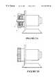
- FIG. 1being an exploded view of an electric motor.
- FIG. 2Ais a side assembly of the arrangement shown in FIG. 1 showing in cross-section the important aspects of the gear assembly but not showing the electric motor nor any mount or input shaft therefrom in section.
- FIG. 2Bis a side elevation of the arrangement of FIG. 2 A.
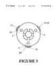
- FIG. 3is a plan view of one embodiment which provides a cage or housing which provides three (by way of example—there could, for example, be six) axles within the housing.
- FIG. 4is a diagrammatic view of the relationship of a plurality of three input 25 planetary gears with their input side internal gear and a corresponding arrangement of a plurality of three output planetary gears with their output internal gear.
- FIG. 5is a more preferred arrangement to that of FIG. 4 where the pitch circle diameter A′ corresponds exactly to that of B′ and preferably there are corresponding pitch circle diameters for the two sets of planetary gears.
- FIG. 6is a diagrammatic view looking along the plane of a sectional door showing how the edgewise rollers thereof (preferably located at or parallel to the pivot axis between sections) can be guided reproducibly in a known manner in a known side track for such doors.
- FIG. 7is a close up of the engagement of the output gear of or driven by a gear assembly meshing in the flexible rack.
- FIG. 8is a similar view to that of FIG. 2B but showing the deformable rack within its channel which runs preferably adjacent the channel in which the wheels, rollers or the like of the preferred sectional door also runs.
- FIG. 9shows the form(s) of a preferred flexible rack of the present invention and in such a way as to demonstrate how it may be made by progressive moulding steps.
- FIGS. 10A and 10Bshow the two means by which the lower section of a sectional door is engaged to the rack.
- FIG. 11is a view of an alternative preferred rack in accordance with the present invention having its bifurcated legs in longitudinally projected transverse section located over a wall of a channel type track within which a tracking element (for example, a wheel) of a panel.
- a tracking elementfor example, a wheel
- FIG. 12is a view along the rotational axis of the tracking wheels of a sectioned door showing the convex curvature of part of the tracking locus and the intermeshing and indexing of the driving pinion therewith,
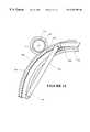
- FIG. 13is a perspective of a rack in accordance with the alternative preferred form of the present invention showing the lower most region thereof.
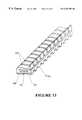
- FIG. 14is a top view of a rack as shown in FIG. 13 (ie; that side having the meshing teeth elements and the transverse interruptions thereof which are the preferred indexing feature of the present invention).
- FIG. 15is an end view of the rack.
- FIG. 16is a side view of a rack of FIG. 14 showing the bifurcation.
- FIG. 17is a bottom view of the arrangement shown in FIG. 14 showing the preferably segmented portions of the rack which are to provide that part of the rack inside of the wall in use.
- FIG. 18is an end view of the rack of FIG. 17 .
- FIG. 19is the opposite side view to that depicted in FIG. 16, ie; that which connects the two portions of the bifurcated transverse section.
- the invention of our New Zealand Patent Specification No. 299720(equivalent to PCT/NZ97/00144) relates to the gearing assembly as well as the related methods and use and includes combinations thereof in respect of door and/or other structures as described and indeed any use thereof for winching or any other such purpose.
- the full content thereofis here introduced by way of reference.
- That inventionrecognises a self braking affect which occurs in the arrangement as depicted when the arrangement as shown in FIGS. 1-3 includes the arrangement as shown in FIG. 5 where, for example, the number of teeth respectively on the input and output internal gears is 36 and 37 respectively and the pitch circle diameters are identical.
- a housing-like structure 1which includes an internal gear 2 (which is the input gear).
- the input shaft 3rotatable relative to the preferably fixed internal gear 2
- the input shaft 3preferably of an electric motor but of any appropriate input means including a hand cranked input.
- a mount, spider or housing 4Splined, keyed or otherwise affixed to that input shaft 3 is a mount, spider or housing 4 which defines a plurality of axes 5 which lie on the circle 6 shown in FIG. 5 .
- Each of these axes 5is defined preferably by axles common for both the planetary gears 7 of the input side and the planetary gears 8 of the output side.
- the output side planetary gears 8mesh with an internal gear 9 which preferably is formed in a member or structure that preferably includes (as part of the output means) a gear 10 .
- the relationship between the pitch circle diameter A′ of the input internal gear 2 and the pitch circle diameter B′ of the output internal gear 9is such that they are identical as shown in FIG. 5 .
- the sets of planetary gears 7 and 8(preferably of identical form) rotate on a common set of axles within the same mount or on the same mount 4 . Therefore the pitch circle diameters C′ and D′ are identical notwithstanding the disparity of (preferably one) teeth between the 36 and 37 teeth of the internal gears 2 and 9 respectively.
- the arrangement as depicted in FIG. 4is somewhat different and whilst still confined, by way of example, to an input side internal gear of 36 teeth and an output side internal gear of 37 teeth there is a disparity in the pitch circle diameters.
- the pitch circle diameter Acould be for example 50.80 mm while the pitch circle diameter B could be 52.20 mm.
- the pitch circle diameters C and Dare respectively 16.23 mm and 17.63 mm in order to provide some semblance of self braking.
- the self brakinghowever, notwithstanding the disparate tooth numbers on pitch circles A and B (preferably a disparity of one), is not as good as where the pitch circle diameters are identical (eg. as in the case of FIG. 5 ).
- the term “self braking”means no more than the ability to resist the transmission of movement back through the gear assembly from the output side.
- the preferred form of that inventionhowever has a direct input shaft without an sun gear and simply drives a plurality of spaced planetary axle members which on the input side have idle gears driven by the fixed “input” side internal gear so that the thus driven idle input gears directly drive the planetary gears of the output side thereby imparting a rotational drive (and a drive of significantly increased torque) onto the internal gear of the output side.
- the arrangement as shown irrespective of the number of planetary gear sets (which are preferably identical on both the input and output sides)is such that as shown in FIG. 5 the planetary gear pairs 7 A and 8 A can be moulded with the teeth in phase. Because of the disparity of one between the input and output internal gears preferably however there is a corresponding out of phase relationship between 7 B and 8 B and between 7 C and 8 C.
- the rackcan configure to a locus parallel to that of the rollers of the door or the equivalent.
- a sectional door as might be used for a garageis tracked upwardly and back from the top of a door portal, the sections 11 of the door being supported by rollers at each edge. These rollers 12 are guided within a channel 13 which preferably forms part of a structure 14 .
- Structure 14(best seen by reference to FIG. 8, not only defines the channel 13 but also another channel 15 (preferably at least in part constricted at its opening—such a constriction not being shown in FIG. 8) which receives there within a flexible or deformable rack 16 preferably to be driven by the output gear 10 of the gear assembly previously described.
- the flexible rackis a member having teeth 17 (see FIG. 9) incrementally moulded thereon singly or preferably in groups (preferably simultaneously as a core or other framing member is preferably configured by the moulding elements to ensure a good grip of the moulded elements thereon).
- the flexible rackis provided with teeth 17 on at least that side to be driven as shown in FIG. 7 preferably on a convex curve side of the exposed part of the flexible rack.
- the rackis formed on high tensile strip steel 18 having periodic ridges, kinks or the like 19 (dimples and/or possible even perforations may suffice) onto which the moulded components are formed.
- teeth structures on both sidesWhile shown in FIG. 9 there are teeth structures on both sides, this is not a necessity. Indeed it is not a necessity also for any such teeth on both sides or any other structure on the non-driven side of the rack to be coincident with projections on the driven side. It is desirable however to maximise flexibility by maintaining a thinness of section through the moulded part of the composite rack between the teeth-like structures.
- an upstand or key form 20 formed by the same moulding operation that forms the teeth to the right as shown in FIG. 9can be used in a subsequent presentation within the mould means to key or index upstand 20 internally of a tooth of the next mould sequence.
- the kinks or ridges 19are indexed to be within the mass of the teeth 17 .
- the flexible rackPreferably there is fixing of the flexible rack at one point only of the door.
- a sectional doorbecause of the variations in length of the door (as it concertinas slightly during its opening) it is not appropriate to fix the flexible rack at each end. It is better to attach at one point only (preferably the lower end although in other forms the upper end will suffice).
- any form of mechanical connection of the door to the flexible rackis sufficient since the rack is capable of operating in both compression and in tension since it is confined guidably within its channel and is preferably structurally strong enough to cope with loadings.
- both ends of the rackespecially the end preferably attached to the door section, irrespective of the door condition [fully open, fully closed, and in between] are still within tracking (eg. a channel) for the rack.
- the rackmay be guidable on a rail preferably the track is a channel.
- FIG. 10Ashows the use of a linkage arm 21 pivotally attached at 22 and 23 respectively to the door section 11 and the rack 6 .
- FIG. 10Bshows a different form where a linking plate 24 fixed to the door section (or framing thereof) 11 includes an end to capture a projection 25 of the rack.
- the rackcould be used to initiate directly mechanical switches or to initiate optical switching means depending on its positioning within its locus of movement and this could be moved to set the door operator in any appropriate known way so that it does not drive beyond the fully closed condition nor drive beyond the fully open condition.
- a clutched arrangement(whether a true friction clutch or more preferably a meshed or keyed or dogged inter-engagement type clutch can be utilised.
- Such an arrangementcan be provided as part of the input means or as part of the out from the preferred reduction gearing assembly. Any such system will suffice.
- suitable plasticsinclude acetyl plastics and/or nylons as the disparate plastic types.
- the alternative form of the present inventionrecognises the capability as best seen in FIG. 11 of using an existing track 101 of a door which provides a groove within which a wheel 102 tracks and carries the sections 103 of a sectioned door.
- the rack 104 with its tooth side 105has its bifurcated legs (defined by longitudinal projection of the transverse section) located over and on either side of the wall 106 of the track 101 .
- This bifurcated featureresults from the gap 107 best seen in FIG. 13 with those parts 108 adapted to lie inside of the wall on which the bifurcated rack is located and with that region 109 adapted to lie outside of the wall.
- the segmenting of the side including the parts 108facilitates bending of the rack about a locus which presents the side 109 in a convex meshing condition.
- the region 109preferably is moulded about a longitudinal member 110 adapted to take loads in tension eg; steel, carbon fibre, Kevlar, etc. and of course the portion 109 also has the teeth 105 moulded therein.
- the teeth 105are separated to provide a keying or indexing groove 111 longitudinally of the rack into which a disk or other member 112 of the pinion 113 can index whilst the teeth 114 of the pinion 113 mesh with the teeth 105 .
Landscapes
- Engineering & Computer Science (AREA)
- General Engineering & Computer Science (AREA)
- Mechanical Engineering (AREA)
- Power-Operated Mechanisms For Wings (AREA)
Abstract
Description
Claims (26)
Applications Claiming Priority (5)
| Application Number | Priority Date | Filing Date | Title |
|---|---|---|---|
| NZ299721 | 1996-11-08 | ||
| NZ29972196ANZ299721A (en) | 1996-11-08 | 1996-11-08 | Hinged panel door assembly having rack moving substantially parallel to door tracks |
| PCT/NZ1997/000143WO1998021438A1 (en) | 1996-11-08 | 1997-10-24 | A rack and pinion door drive system |
| NZ33009898ANZ330098A (en) | 1998-03-31 | 1998-03-31 | A rack and pinion door drive device for an automatic door with rack having bifurcate transverse section to locate onto rail of door track |
| NZ330098 | 1998-03-31 |
Related Parent Applications (1)
| Application Number | Title | Priority Date | Filing Date |
|---|---|---|---|
| PCT/NZ1997/000143Continuation-In-PartWO1998021438A1 (en) | 1996-11-08 | 1997-10-24 | A rack and pinion door drive system |
Publications (1)
| Publication Number | Publication Date |
|---|---|
| US6257303B1true US6257303B1 (en) | 2001-07-10 |
Family
ID=26651685
Family Applications (1)
| Application Number | Title | Priority Date | Filing Date |
|---|---|---|---|
| US09/280,516Expired - Fee RelatedUS6257303B1 (en) | 1996-11-08 | 1999-03-31 | Rack and pinion door drive system |
Country Status (1)
| Country | Link |
|---|---|
| US (1) | US6257303B1 (en) |
Cited By (39)
| Publication number | Priority date | Publication date | Assignee | Title |
|---|---|---|---|---|
| US20030084614A1 (en)* | 2001-11-07 | 2003-05-08 | Dean Pettit | Integrated tilt/sash lock assembly |
| US20040060669A1 (en)* | 2002-05-09 | 2004-04-01 | The Chamberlain Group, Inc. | Drive system for garage door |
| US20040168370A1 (en)* | 2002-11-07 | 2004-09-02 | Dean Pettit | Integrated tilt/sash lock assembly |
| US20040177934A1 (en)* | 2003-03-10 | 2004-09-16 | The Chamberlain Group, Inc. | Garage door movement apparatus |
| US20050016067A1 (en)* | 2002-11-07 | 2005-01-27 | Dean Pettit | Integrated tilt/sash lock assembly |
| US20050225071A1 (en)* | 2001-12-21 | 2005-10-13 | Joseph Cicansky | Vehicle mud flap |
| US20060081077A1 (en)* | 2004-10-14 | 2006-04-20 | Spakowski Joseph G | Rack and pinion transmission for a pintle valve |
| US20060192391A1 (en)* | 2005-02-10 | 2006-08-31 | Dean Pettit | Integrated tilt/sash lock assembly |
| US20060283559A1 (en)* | 2005-06-21 | 2006-12-21 | Hunter Douglas Industries Bv | Operating device for a window covering |
| US20070095487A1 (en)* | 2005-09-12 | 2007-05-03 | The Chamberlain Group, Inc. | Moveable barrier systems |
| US20070180770A1 (en)* | 2005-07-28 | 2007-08-09 | Flory Edward C | Integrated tilt/sash lock assembly |
| US20070200519A1 (en)* | 2006-02-27 | 2007-08-30 | Overhead Door Corporation | Barrier operator with flexible drive member |
| US20070209281A1 (en)* | 2001-11-07 | 2007-09-13 | Flory Edward C | Integrated tilt/sash lock assembly |
| USD553950S1 (en) | 2006-07-26 | 2007-10-30 | Newell Operating Company | Sash lock housing |
| USD553947S1 (en) | 2006-07-26 | 2007-10-30 | Newell Operating Company | Integrated tilt/sash lock assembly |
| USD554473S1 (en) | 2006-07-26 | 2007-11-06 | Newell Operating Company | Tilt-latch |
| USD554973S1 (en) | 2006-07-26 | 2007-11-13 | Newell Operating Company | Sash lock housing |
| USD554971S1 (en) | 2006-07-26 | 2007-11-13 | Newell Operating Company | Sash lock handle |
| USD575627S1 (en) | 2007-11-16 | 2008-08-26 | Newell Operating Company | Sash lock housing |
| US20090206777A1 (en)* | 2008-02-19 | 2009-08-20 | Hassan Taheri | High torque movable barrier actuation at low speeds utilizing a hub motor |
| US20100024308A1 (en)* | 2008-07-29 | 2010-02-04 | Bruce Arthur Coubray | Barrier Operator With Rack And Pinion Drive And Coupling Assembly For An Integrated Door And Operator |
| US20110210655A1 (en)* | 2010-02-26 | 2011-09-01 | Electrolux Home Products, Inc. | Drawer assembly |
| US8205920B2 (en) | 2008-04-28 | 2012-06-26 | Newell Operating Company | Sash lock with forced entry resistance |
| WO2013016777A1 (en)* | 2011-08-03 | 2013-02-07 | Daylee Pty Ltd | Garage door drive apparatus |
| US8590209B1 (en)* | 2012-09-27 | 2013-11-26 | The Chamberlain Group, Inc. | Air spring counterbalance |
| US20140162822A1 (en)* | 2011-12-19 | 2014-06-12 | Xerox Corporation | Flexible Gear Rack Carriage Transport In A Printing Apparatus |
| US20150020617A1 (en)* | 2013-07-19 | 2015-01-22 | Rodney H. Neumann | Sprocket-Driven Door |
| US20150047443A1 (en)* | 2013-08-13 | 2015-02-19 | Timotion Technology Co., Ltd. | Actuator with multi-stage gears |
| EP2860080A3 (en)* | 2013-09-23 | 2015-07-08 | Knorr-Bremse Gesellschaft mit beschränkter Haftung | Material pairing for a rack and pinion drive of a sliding door module/swinging door module |
| US9752369B2 (en) | 2011-05-24 | 2017-09-05 | Overhead Door Corporation | Barrier operator mechanical transmission assembly |
| US10000960B2 (en)* | 2015-08-04 | 2018-06-19 | RMB Systems, LLC | Drive device for a movable barrier |
| US10119310B2 (en) | 2014-03-06 | 2018-11-06 | Vision Industries Group, Inc. | Combination sash lock and tilt latch with improved interconnection for blind mating of the latch to the lock |
| US10352412B2 (en)* | 2017-03-20 | 2019-07-16 | King Slide Works Co., Ltd. | Gear arrangement |
| US10563446B2 (en) | 2013-12-09 | 2020-02-18 | Faac International Inc. | Movable barrier operator with removable power supply module |
| US10570652B2 (en) | 2014-03-06 | 2020-02-25 | Vision Industries Group, Inc. | Integrated sash lock and tilt latch combination using one lock for two tilt latches |
| US10704297B2 (en) | 2014-03-06 | 2020-07-07 | Vision Industries, Inc. | Impact resistant lock and tilt latch combination for a sliding sash window |
| US10844642B2 (en) | 2014-03-06 | 2020-11-24 | Vision Industries Group, Inc. | Combination four-position sash lock and tilt latch also functioning as a window opening control device |
| TWI740681B (en)* | 2020-04-30 | 2021-09-21 | 鍾玉波 | Mechanical semi-automatic sliding door driving mechanism |
| CN116201448A (en)* | 2023-02-21 | 2023-06-02 | 江苏鼎龙软件科技有限公司 | A full life non-counterweight construction industry climbing door and its control method |
Citations (29)
| Publication number | Priority date | Publication date | Assignee | Title |
|---|---|---|---|---|
| US2251308A (en)* | 1940-07-15 | 1941-08-05 | Washington Joseph Andrew | Jack |
| US3061006A (en)* | 1960-02-04 | 1962-10-30 | Lester W Hazlett | Shade construction |
| US3591981A (en)* | 1969-03-10 | 1971-07-13 | Tilt A Door Corp | Door operator |
| FR2067726A5 (en) | 1969-12-14 | 1971-08-20 | Cousin Cie Ets A & M Freres | |
| DE2330461A1 (en) | 1972-07-04 | 1974-01-24 | Wilhelm Wuerzinger | ENCLOSURE FOR A VERTICAL SLIDING GATE |
| DE2645803A1 (en) | 1976-10-09 | 1978-04-13 | Werner Haake | Up-and-over garage door - has dropping brake on actuating shaft with centrifugal brake |
| US4188752A (en) | 1977-04-13 | 1980-02-19 | Faiveley S.A. | Oblique-displacement sliding door |
| EP0033639A2 (en) | 1980-02-01 | 1981-08-12 | Chubb Integrated Systems Limited | Equipment including retractable protective-screens |
| FR2541717A1 (en) | 1983-02-25 | 1984-08-31 | Drieux Ets R | Device for the linear drive of at least one element, such as a door of a vehicle, lift or the like |
| US4541293A (en)* | 1981-06-23 | 1985-09-17 | Thomson Csf | Load-bearing telescopic slide assembly and X-ray installation equipped therewith |
| US4570617A (en)* | 1983-02-05 | 1986-02-18 | Baus Heinz Georg | Massaging device |
| AU4417385A (en) | 1984-09-27 | 1986-04-10 | International Business Machines Corp. | Endless forms feed tractor belt and method of making |
| EP0313119A1 (en) | 1987-10-21 | 1989-04-26 | FAAC S.p.A. | Sectional element motor-driven for controlling overhead doors |
| WO1990012185A1 (en) | 1989-04-07 | 1990-10-18 | Remote-A-Matic Usa, Inc. | Low profile sliding door opener |
| US4984387A (en) | 1989-06-08 | 1991-01-15 | 501 Manaras Auto Doors, Inc. | Door drive mechanism adapter unit |
| DE4016707A1 (en) | 1990-05-24 | 1991-11-28 | Baumeister & Ostler Gmbh Co | Electrically driven roller shutter for vehicle - has flexible drive coupling to support bars for shutter |
| GB2266921A (en) | 1992-05-15 | 1993-11-17 | Ona Electro Erosion | An automatic door opening system. |
| WO1994013917A1 (en) | 1992-12-10 | 1994-06-23 | Girotto, Pietro | Electromagnetic actuator for door units and the like |
| US5351441A (en) | 1992-03-02 | 1994-10-04 | Marantec Antriebs-Und Steuerungstechnik Gmbh & Co. Produktions Kg | Sliding door |
| WO1995030064A1 (en) | 1994-04-29 | 1995-11-09 | Dynaco International | Closure device with a flexible screen |
| US5515650A (en) | 1993-04-08 | 1996-05-14 | Machill; Rolf | Force transmission element on a sliding gate |
| DE29609982U1 (en) | 1996-06-05 | 1996-08-22 | Dowaldwerke Adolph Dowald GmbH, 28199 Bremen | Drive system for a curved sliding door |
| US5572829A (en)* | 1995-06-29 | 1996-11-12 | Stoltenberg; Donald A. | Power operated garage door |
| DE19628289A1 (en) | 1995-07-13 | 1997-02-27 | Rudolf Liberda | Servo drive for door |
| DE19538798A1 (en) | 1995-10-18 | 1997-04-24 | Schwab Christian Dipl Designer | Rack gearing to convert reciprocating motion into rotary motion |
| US5680729A (en)* | 1995-02-09 | 1997-10-28 | The Pickwick Corporation | System for opening and closing a gate |
| US5842598A (en)* | 1995-09-04 | 1998-12-01 | Asahi Seiko Co., Ltd. | Combination storage system and compact ejection mechanisms |
| US5918418A (en)* | 1997-05-02 | 1999-07-06 | Doorking, Inc. | Overhead door operator |
| US5921611A (en)* | 1992-07-13 | 1999-07-13 | Joalto Design Inc. | Upwardly retracting vehicle door |
- 1999
- 1999-03-31USUS09/280,516patent/US6257303B1/ennot_activeExpired - Fee Related
Patent Citations (29)
| Publication number | Priority date | Publication date | Assignee | Title |
|---|---|---|---|---|
| US2251308A (en)* | 1940-07-15 | 1941-08-05 | Washington Joseph Andrew | Jack |
| US3061006A (en)* | 1960-02-04 | 1962-10-30 | Lester W Hazlett | Shade construction |
| US3591981A (en)* | 1969-03-10 | 1971-07-13 | Tilt A Door Corp | Door operator |
| FR2067726A5 (en) | 1969-12-14 | 1971-08-20 | Cousin Cie Ets A & M Freres | |
| DE2330461A1 (en) | 1972-07-04 | 1974-01-24 | Wilhelm Wuerzinger | ENCLOSURE FOR A VERTICAL SLIDING GATE |
| DE2645803A1 (en) | 1976-10-09 | 1978-04-13 | Werner Haake | Up-and-over garage door - has dropping brake on actuating shaft with centrifugal brake |
| US4188752A (en) | 1977-04-13 | 1980-02-19 | Faiveley S.A. | Oblique-displacement sliding door |
| EP0033639A2 (en) | 1980-02-01 | 1981-08-12 | Chubb Integrated Systems Limited | Equipment including retractable protective-screens |
| US4541293A (en)* | 1981-06-23 | 1985-09-17 | Thomson Csf | Load-bearing telescopic slide assembly and X-ray installation equipped therewith |
| US4570617A (en)* | 1983-02-05 | 1986-02-18 | Baus Heinz Georg | Massaging device |
| FR2541717A1 (en) | 1983-02-25 | 1984-08-31 | Drieux Ets R | Device for the linear drive of at least one element, such as a door of a vehicle, lift or the like |
| AU4417385A (en) | 1984-09-27 | 1986-04-10 | International Business Machines Corp. | Endless forms feed tractor belt and method of making |
| EP0313119A1 (en) | 1987-10-21 | 1989-04-26 | FAAC S.p.A. | Sectional element motor-driven for controlling overhead doors |
| WO1990012185A1 (en) | 1989-04-07 | 1990-10-18 | Remote-A-Matic Usa, Inc. | Low profile sliding door opener |
| US4984387A (en) | 1989-06-08 | 1991-01-15 | 501 Manaras Auto Doors, Inc. | Door drive mechanism adapter unit |
| DE4016707A1 (en) | 1990-05-24 | 1991-11-28 | Baumeister & Ostler Gmbh Co | Electrically driven roller shutter for vehicle - has flexible drive coupling to support bars for shutter |
| US5351441A (en) | 1992-03-02 | 1994-10-04 | Marantec Antriebs-Und Steuerungstechnik Gmbh & Co. Produktions Kg | Sliding door |
| GB2266921A (en) | 1992-05-15 | 1993-11-17 | Ona Electro Erosion | An automatic door opening system. |
| US5921611A (en)* | 1992-07-13 | 1999-07-13 | Joalto Design Inc. | Upwardly retracting vehicle door |
| WO1994013917A1 (en) | 1992-12-10 | 1994-06-23 | Girotto, Pietro | Electromagnetic actuator for door units and the like |
| US5515650A (en) | 1993-04-08 | 1996-05-14 | Machill; Rolf | Force transmission element on a sliding gate |
| WO1995030064A1 (en) | 1994-04-29 | 1995-11-09 | Dynaco International | Closure device with a flexible screen |
| US5680729A (en)* | 1995-02-09 | 1997-10-28 | The Pickwick Corporation | System for opening and closing a gate |
| US5572829A (en)* | 1995-06-29 | 1996-11-12 | Stoltenberg; Donald A. | Power operated garage door |
| DE19628289A1 (en) | 1995-07-13 | 1997-02-27 | Rudolf Liberda | Servo drive for door |
| US5842598A (en)* | 1995-09-04 | 1998-12-01 | Asahi Seiko Co., Ltd. | Combination storage system and compact ejection mechanisms |
| DE19538798A1 (en) | 1995-10-18 | 1997-04-24 | Schwab Christian Dipl Designer | Rack gearing to convert reciprocating motion into rotary motion |
| DE29609982U1 (en) | 1996-06-05 | 1996-08-22 | Dowaldwerke Adolph Dowald GmbH, 28199 Bremen | Drive system for a curved sliding door |
| US5918418A (en)* | 1997-05-02 | 1999-07-06 | Doorking, Inc. | Overhead door operator |
Non-Patent Citations (3)
| Title |
|---|
| Derwent Abstract Accession No: 86-059936/09, JP 61-013061 A, (Asahi Chemical Ind KK) , Jan. 21, 1986. |
| Derwent Abstract Accession No: B2894C/06, NL 7807427 A, (SCHIJF) , Jan 14, 1980. |
| Patent Abstracts of Japan, M-1132, p. 25, JP 3-87487 A, (Toyo Exterior Co Ltd) , Apr. 12, 1991. |
Cited By (71)
| Publication number | Priority date | Publication date | Assignee | Title |
|---|---|---|---|---|
| US6957513B2 (en) | 2001-11-07 | 2005-10-25 | Newell Operating Company | Integrated tilt/sash lock assembly |
| US7070211B2 (en) | 2001-11-07 | 2006-07-04 | Newell Operating Company | Integrated tilt/sash lock assembly |
| US20030110699A1 (en)* | 2001-11-07 | 2003-06-19 | Eenigenburg Mark B. | Integrated tilt/sash lock assembly |
| US20030084614A1 (en)* | 2001-11-07 | 2003-05-08 | Dean Pettit | Integrated tilt/sash lock assembly |
| US20090241429A1 (en)* | 2001-11-07 | 2009-10-01 | Newell Operating Company | Integrated tilt/sash lock assembly |
| US20070209281A1 (en)* | 2001-11-07 | 2007-09-13 | Flory Edward C | Integrated tilt/sash lock assembly |
| US8020904B2 (en) | 2001-11-07 | 2011-09-20 | Newell Operating Company | Integrated tilt/sash lock assembly |
| US7481470B2 (en) | 2001-11-07 | 2009-01-27 | Newell Operating Company | Integrated tilt/sash lock assembly |
| US20030110698A1 (en)* | 2001-11-07 | 2003-06-19 | Polowinczak Allen D. | Integrated tilt/sash lock assembly |
| US20060207181A1 (en)* | 2001-11-07 | 2006-09-21 | Polowinczak Allen D | Integrated tilt/sash lock assembly |
| US7013603B2 (en) | 2001-11-07 | 2006-03-21 | Newell Operating Company | Integrated tilt/sash lock assembly |
| US20050225071A1 (en)* | 2001-12-21 | 2005-10-13 | Joseph Cicansky | Vehicle mud flap |
| US6883579B2 (en) | 2002-05-09 | 2005-04-26 | The Chamberlain Group, Inc. | Drive system for garage door |
| US20040060669A1 (en)* | 2002-05-09 | 2004-04-01 | The Chamberlain Group, Inc. | Drive system for garage door |
| US20050016067A1 (en)* | 2002-11-07 | 2005-01-27 | Dean Pettit | Integrated tilt/sash lock assembly |
| US20100050528A1 (en)* | 2002-11-07 | 2010-03-04 | Newell Operating Company | Integrated tilt/sash lock assembly |
| US7607262B2 (en) | 2002-11-07 | 2009-10-27 | Newell Operating Company | Integrated tilt/sash lock assembly |
| US20040168370A1 (en)* | 2002-11-07 | 2004-09-02 | Dean Pettit | Integrated tilt/sash lock assembly |
| US8132369B2 (en) | 2002-11-07 | 2012-03-13 | Newell Operating Company | Integrated tilt/sash lock assembly |
| US20040177934A1 (en)* | 2003-03-10 | 2004-09-16 | The Chamberlain Group, Inc. | Garage door movement apparatus |
| US7252618B2 (en)* | 2004-10-14 | 2007-08-07 | Delphi Technologies, Inc. | Rack and pinion transmission for a pintle valve |
| US20060081077A1 (en)* | 2004-10-14 | 2006-04-20 | Spakowski Joseph G | Rack and pinion transmission for a pintle valve |
| US20060192391A1 (en)* | 2005-02-10 | 2006-08-31 | Dean Pettit | Integrated tilt/sash lock assembly |
| US20060283559A1 (en)* | 2005-06-21 | 2006-12-21 | Hunter Douglas Industries Bv | Operating device for a window covering |
| US7581579B2 (en)* | 2005-06-21 | 2009-09-01 | Hunter Douglas Industries B.V. | Operating device for a window covering |
| US20070180770A1 (en)* | 2005-07-28 | 2007-08-09 | Flory Edward C | Integrated tilt/sash lock assembly |
| US7976077B2 (en) | 2005-07-28 | 2011-07-12 | Newell Operating Company | Integrated tilt/sash lock assembly |
| US20070095487A1 (en)* | 2005-09-12 | 2007-05-03 | The Chamberlain Group, Inc. | Moveable barrier systems |
| US7997324B2 (en) | 2005-09-12 | 2011-08-16 | The Chamberlain Group, Inc. | Moveable barrier systems |
| US7372225B2 (en) | 2006-02-27 | 2008-05-13 | Overhead Door Corporation | Barrier operator with flexible drive member |
| US20070200519A1 (en)* | 2006-02-27 | 2007-08-30 | Overhead Door Corporation | Barrier operator with flexible drive member |
| USD554971S1 (en) | 2006-07-26 | 2007-11-13 | Newell Operating Company | Sash lock handle |
| USD554973S1 (en) | 2006-07-26 | 2007-11-13 | Newell Operating Company | Sash lock housing |
| USD554473S1 (en) | 2006-07-26 | 2007-11-06 | Newell Operating Company | Tilt-latch |
| USD553947S1 (en) | 2006-07-26 | 2007-10-30 | Newell Operating Company | Integrated tilt/sash lock assembly |
| USD553950S1 (en) | 2006-07-26 | 2007-10-30 | Newell Operating Company | Sash lock housing |
| USD575627S1 (en) | 2007-11-16 | 2008-08-26 | Newell Operating Company | Sash lock housing |
| US7816879B2 (en)* | 2008-02-19 | 2010-10-19 | Viking Access Systems, Llc | High torque movable barrier actuation at low speeds utilizing a hub motor |
| US20100319257A1 (en)* | 2008-02-19 | 2010-12-23 | Hassan Taheri | High torque movable barrier actuation at low speeds utilizing a hub motor |
| US20090206777A1 (en)* | 2008-02-19 | 2009-08-20 | Hassan Taheri | High torque movable barrier actuation at low speeds utilizing a hub motor |
| US8205920B2 (en) | 2008-04-28 | 2012-06-26 | Newell Operating Company | Sash lock with forced entry resistance |
| US8935883B2 (en)* | 2008-07-29 | 2015-01-20 | The Chamberlain Group, Inc. | Barrier operator with rack and pinion drive and coupling assembly for an integrated door and operator |
| US20100024308A1 (en)* | 2008-07-29 | 2010-02-04 | Bruce Arthur Coubray | Barrier Operator With Rack And Pinion Drive And Coupling Assembly For An Integrated Door And Operator |
| US8360539B2 (en) | 2010-02-26 | 2013-01-29 | Electrolux Home Products, Inc. | Drawer assembly |
| WO2011106594A3 (en)* | 2010-02-26 | 2011-11-17 | Electrolux Home Products, Inc. | Drawer assemble |
| US20110210655A1 (en)* | 2010-02-26 | 2011-09-01 | Electrolux Home Products, Inc. | Drawer assembly |
| US10584527B2 (en) | 2011-05-24 | 2020-03-10 | Overhead Door Corporation | Barrier operator mechanical transmission assembly |
| US9752369B2 (en) | 2011-05-24 | 2017-09-05 | Overhead Door Corporation | Barrier operator mechanical transmission assembly |
| US9359802B2 (en) | 2011-08-03 | 2016-06-07 | Daylee Pty Ltd. | Garage door drive apparatus |
| WO2013016777A1 (en)* | 2011-08-03 | 2013-02-07 | Daylee Pty Ltd | Garage door drive apparatus |
| AU2012289837B2 (en)* | 2011-08-03 | 2017-08-24 | Daylee Pty Ltd | Garage door drive apparatus |
| US20140162822A1 (en)* | 2011-12-19 | 2014-06-12 | Xerox Corporation | Flexible Gear Rack Carriage Transport In A Printing Apparatus |
| US9500261B2 (en)* | 2011-12-19 | 2016-11-22 | Xerox Corporation | Flexible gear rack carriage transport in a printing apparatus |
| US8590209B1 (en)* | 2012-09-27 | 2013-11-26 | The Chamberlain Group, Inc. | Air spring counterbalance |
| US9103149B2 (en) | 2012-09-27 | 2015-08-11 | The Chamberlain Group, Inc. | Air spring counterbalance |
| US8813429B2 (en)* | 2012-09-27 | 2014-08-26 | The Chamberlain Group, Inc. | Method of using an air spring counterbalance |
| US9428948B2 (en) | 2012-09-27 | 2016-08-30 | The Chamberlain Group, Inc. | Air spring counterbalance |
| US20150020617A1 (en)* | 2013-07-19 | 2015-01-22 | Rodney H. Neumann | Sprocket-Driven Door |
| US20150047443A1 (en)* | 2013-08-13 | 2015-02-19 | Timotion Technology Co., Ltd. | Actuator with multi-stage gears |
| US9400040B2 (en)* | 2013-08-13 | 2016-07-26 | Timotion Technology Co., Ltd. | Actuator with multi-stage gears |
| EP2860080A3 (en)* | 2013-09-23 | 2015-07-08 | Knorr-Bremse Gesellschaft mit beschränkter Haftung | Material pairing for a rack and pinion drive of a sliding door module/swinging door module |
| US10563446B2 (en) | 2013-12-09 | 2020-02-18 | Faac International Inc. | Movable barrier operator with removable power supply module |
| US10119310B2 (en) | 2014-03-06 | 2018-11-06 | Vision Industries Group, Inc. | Combination sash lock and tilt latch with improved interconnection for blind mating of the latch to the lock |
| US10323446B2 (en) | 2014-03-06 | 2019-06-18 | Vision Industries Group, Inc. | Integrated sash lock and tilt latch combination with improved interconnection capability therebetween |
| US10570652B2 (en) | 2014-03-06 | 2020-02-25 | Vision Industries Group, Inc. | Integrated sash lock and tilt latch combination using one lock for two tilt latches |
| US10704297B2 (en) | 2014-03-06 | 2020-07-07 | Vision Industries, Inc. | Impact resistant lock and tilt latch combination for a sliding sash window |
| US10844642B2 (en) | 2014-03-06 | 2020-11-24 | Vision Industries Group, Inc. | Combination four-position sash lock and tilt latch also functioning as a window opening control device |
| US10000960B2 (en)* | 2015-08-04 | 2018-06-19 | RMB Systems, LLC | Drive device for a movable barrier |
| US10352412B2 (en)* | 2017-03-20 | 2019-07-16 | King Slide Works Co., Ltd. | Gear arrangement |
| TWI740681B (en)* | 2020-04-30 | 2021-09-21 | 鍾玉波 | Mechanical semi-automatic sliding door driving mechanism |
| CN116201448A (en)* | 2023-02-21 | 2023-06-02 | 江苏鼎龙软件科技有限公司 | A full life non-counterweight construction industry climbing door and its control method |
Similar Documents
| Publication | Publication Date | Title |
|---|---|---|
| US6257303B1 (en) | Rack and pinion door drive system | |
| US8800206B2 (en) | Motorized closure assembly | |
| US7717155B2 (en) | Pivoting barrier operator system with integral cable storage drum and transfer assembly | |
| EP0820889B1 (en) | Swivel-sliding door system for a vehicle | |
| US4128120A (en) | Tambour door and housing assembly | |
| EP2034218B1 (en) | Push-pull chain and actuator | |
| JPH04231584A (en) | Connected panel type overhead door device for garage | |
| DE102004011492A1 (en) | Garage door moving means | |
| WO1998021438A1 (en) | A rack and pinion door drive system | |
| US20040172883A1 (en) | Drive unit for power operated vehicle closure | |
| AU761744B2 (en) | A rack and pinion door drive system | |
| US6854212B2 (en) | Belt drive system for sliding vehicle door | |
| CA2483356C (en) | Direct transmission garage door opener | |
| JP2001003638A (en) | Motor-driven slide door device for vehicle | |
| US3499478A (en) | Door assembly | |
| AU2002318883B2 (en) | A Rack and Pinion Door Drive System | |
| JP4551466B2 (en) | Double sliding platform gate | |
| AU2007202497A1 (en) | A rack and pinion door drive system | |
| JP2008280034A5 (en) | ||
| EP0934477A1 (en) | A gear assembly | |
| CN2486063Y (en) | Hand and electric driven two purpose curtain rail | |
| CN100384653C (en) | Drive unit for powered hood | |
| SU895878A1 (en) | Lift cabin movable-apart door drive | |
| JPH10129959A (en) | Elevator door opening and closing device | |
| JP2504477Y2 (en) | Electric multiple sliding door device |
Legal Events
| Date | Code | Title | Description |
|---|---|---|---|
| AS | Assignment | Owner name:HOWICK ENGINEERING LIMITED, NEW ZEALAND Free format text:ASSIGNMENT OF ASSIGNORS INTEREST;ASSIGNORS:COUBRAY, BRUCE ARTHUR;COUBRAY, ALLAN KEITH;REEL/FRAME:010058/0864 Effective date:19990511 | |
| FPAY | Fee payment | Year of fee payment:4 | |
| AS | Assignment | Owner name:HOWICK LIMITED, NEW ZEALAND Free format text:ASSIGNMENT OF ASSIGNORS INTEREST;ASSIGNOR:HOWICK ENGINEERING LIMITED;REEL/FRAME:017555/0473 Effective date:20060405 | |
| AS | Assignment | Owner name:POSITION INDICATING CORPORATION, ILLINOIS Free format text:ASSIGNMENT OF ASSIGNORS INTEREST;ASSIGNORS:HOWICK LIMITED;COUBRAY, BRUCE ARTHUR;COUBRAY, ALAN KEITH;REEL/FRAME:018026/0260 Effective date:20060428 | |
| AS | Assignment | Owner name:THE CHAMBERLAIN GROUP, INC., ILLINOIS Free format text:ASSIGNMENT OF ASSIGNORS INTEREST;ASSIGNOR:POSITION INDICATING CORPORATION;REEL/FRAME:018420/0249 Effective date:20061023 | |
| FPAY | Fee payment | Year of fee payment:8 | |
| FEPP | Fee payment procedure | Free format text:PAT HOLDER NO LONGER CLAIMS SMALL ENTITY STATUS, ENTITY STATUS SET TO UNDISCOUNTED (ORIGINAL EVENT CODE: STOL); ENTITY STATUS OF PATENT OWNER: LARGE ENTITY | |
| SULP | Surcharge for late payment | ||
| REMI | Maintenance fee reminder mailed | ||
| LAPS | Lapse for failure to pay maintenance fees | ||
| STCH | Information on status: patent discontinuation | Free format text:PATENT EXPIRED DUE TO NONPAYMENT OF MAINTENANCE FEES UNDER 37 CFR 1.362 | |
| FP | Lapsed due to failure to pay maintenance fee | Effective date:20130710 |