US6257162B1 - Underwater latch and power supply - Google Patents
Underwater latch and power supplyDownload PDFInfo
- Publication number
- US6257162B1 US6257162B1US09/399,314US39931499AUS6257162B1US 6257162 B1US6257162 B1US 6257162B1US 39931499 AUS39931499 AUS 39931499AUS 6257162 B1US6257162 B1US 6257162B1
- Authority
- US
- United States
- Prior art keywords
- tether
- vehicle
- port
- power
- recited
- Prior art date
- Legal status (The legal status is an assumption and is not a legal conclusion. Google has not performed a legal analysis and makes no representation as to the accuracy of the status listed.)
- Expired - Lifetime
Links
- 238000000034methodMethods0.000claimsabstractdescription23
- XLYOFNOQVPJJNP-UHFFFAOYSA-NwaterSubstancesOXLYOFNOQVPJJNP-UHFFFAOYSA-N0.000claimsabstractdescription23
- 239000000463materialSubstances0.000claimsdescription12
- 238000004891communicationMethods0.000description22
- 230000033001locomotionEffects0.000description17
- 238000012546transferMethods0.000description12
- 239000000835fiberSubstances0.000description7
- 238000011084recoveryMethods0.000description7
- 230000013011matingEffects0.000description6
- 239000002184metalSubstances0.000description4
- 229910052751metalInorganic materials0.000description4
- 230000005540biological transmissionEffects0.000description2
- 230000008878couplingEffects0.000description2
- 238000010168coupling processMethods0.000description2
- 238000005859coupling reactionMethods0.000description2
- 238000005553drillingMethods0.000description2
- 238000007667floatingMethods0.000description2
- 230000003993interactionEffects0.000description2
- 230000001788irregularEffects0.000description2
- 238000004519manufacturing processMethods0.000description2
- 238000003032molecular dockingMethods0.000description2
- 238000003909pattern recognitionMethods0.000description2
- 235000020030perryNutrition0.000description2
- 230000008569processEffects0.000description2
- RYGMFSIKBFXOCR-UHFFFAOYSA-NCopperChemical compound[Cu]RYGMFSIKBFXOCR-UHFFFAOYSA-N0.000description1
- 229910000831SteelInorganic materials0.000description1
- 230000009471actionEffects0.000description1
- 230000006978adaptationEffects0.000description1
- 238000009933burialMethods0.000description1
- 238000004140cleaningMethods0.000description1
- 238000010276constructionMethods0.000description1
- 229910052802copperInorganic materials0.000description1
- 239000010949copperSubstances0.000description1
- 238000005520cutting processMethods0.000description1
- 238000005516engineering processMethods0.000description1
- 239000000446fuelSubstances0.000description1
- 238000007689inspectionMethods0.000description1
- 238000012423maintenanceMethods0.000description1
- 230000001404mediated effectEffects0.000description1
- 238000005065miningMethods0.000description1
- 238000012986modificationMethods0.000description1
- 230000004048modificationEffects0.000description1
- 230000003287optical effectEffects0.000description1
- 239000003208petroleumSubstances0.000description1
- 238000009877renderingMethods0.000description1
- 238000011160researchMethods0.000description1
- 230000000087stabilizing effectEffects0.000description1
- 239000010959steelSubstances0.000description1
- 238000012360testing methodMethods0.000description1
Images


Classifications
- B—PERFORMING OPERATIONS; TRANSPORTING
- B63—SHIPS OR OTHER WATERBORNE VESSELS; RELATED EQUIPMENT
- B63C—LAUNCHING, HAULING-OUT, OR DRY-DOCKING OF VESSELS; LIFE-SAVING IN WATER; EQUIPMENT FOR DWELLING OR WORKING UNDER WATER; MEANS FOR SALVAGING OR SEARCHING FOR UNDERWATER OBJECTS
- B63C11/00—Equipment for dwelling or working underwater; Means for searching for underwater objects
- B63C11/34—Diving chambers with mechanical link, e.g. cable, to a base
- B63C11/36—Diving chambers with mechanical link, e.g. cable, to a base of closed type
- B63C11/42—Diving chambers with mechanical link, e.g. cable, to a base of closed type with independent propulsion or direction control
- B—PERFORMING OPERATIONS; TRANSPORTING
- B63—SHIPS OR OTHER WATERBORNE VESSELS; RELATED EQUIPMENT
- B63G—OFFENSIVE OR DEFENSIVE ARRANGEMENTS ON VESSELS; MINE-LAYING; MINE-SWEEPING; SUBMARINES; AIRCRAFT CARRIERS
- B63G8/00—Underwater vessels, e.g. submarines; Equipment specially adapted therefor
- B63G8/001—Underwater vessels adapted for special purposes, e.g. unmanned underwater vessels; Equipment specially adapted therefor, e.g. docking stations
Definitions
- the inventionrelates to the field of systems for deployment, recovery, servicing, and operation of equipment in deep water and methods for utilizing such systems. More particularly, the invention relates to devices having a tether management system and a detachable flying latch vehicle for use in deep water.
- Autonomous underwater vehiclesare subsurface vehicles that are not physically connected to a support platform such as a land-based platform, an offshore platform, or a sea-going vessel.
- ROVsremotely operated vehicle
- the typical physical connection between an ROV and a support platformis referred to as an “umbilical.”
- the umbilicalis usually an armored or unarmored cable containing an electrical and/or hydraulic conduit for providing power to an ROV and a data communications conduit for transmitting signals between an ROV and a support platform.
- An umbilicalthus provides a means for remotely controlling an ROV during underwater operation.
- ROVsare commonly equipped with on-board propulsion systems, navigation systems, communication systems, video systems, lights, and mechanical manipulators so that they can move to an underwater work site and perform a particular task. For example, after being lowered to a subsurface position, a remotely-located technician or pilot can utilize an ROV's on-board navigation and communications systems to “fly” the craft to a worksite. The technician or pilot can then operate the mechanical manipulators or other tools on the ROV to perform a particular job. In this manner, ROVs can be used to perform relatively complex tasks including those involved in drill support, construction support, platform cleaning and inspection, subsurface cable burial and maintenance, deep water salvage, remote tool deployment, subsurface pipeline completion, subsurface pile suction, etc. Although they are quite flexible in that they can be adapted to perform a wide variety of tasks, ROVs are also fairly expensive to operate as they require a significant amount of support, including, for example, a pilot, technicians, and a surface support platform.
- ROVs and other subsurface vehicles that are connected to a surface vessel by a physical linkageare subject to heave-induced damage.
- Heaveis the up and down motion of an object produced by waves on the surface of a body of water.
- Underwater vehicles physically attached to a floating surface platformtherefore move in accord with the surface platform. Therefore, when an underwater vehicle is located near a fixed object such as the sea bed, a pipeline, or a wellhead, heave-induced movement can damage both the vehicle and the fixed object.
- devicessuch as heave-induced motion compensators and tether management systems have been employed to reduce the transfer of heave to underwater vehicles.
- AUVsIn contrast to ROVs, while underwater, AUVs are not subject to heave-mediated damage because they are not usually physically connected to a support platform. Like ROVs, AUVs are useful for performing a variety of underwater operations. Common AUVs are essentially unmanned submarines that contain an on-board power supply, propulsion system, and a pre-programmed control system. In a typical operation, after being placed in the water from a surface platform, an AUV will carry out a pre-programmed mission, then automatically surface for recovery. In this fashion, AUVs can perform subsurface tasks without requiring constant attention from a technician. AUVs are also substantially less expensive to operate than ROVs because they do not require an umbilical connection to an attached surface support platform.
- AUVshave practical limitations rendering them unsuitable for certain underwater operations.
- power in an AUVtypically comes from an on-board power supply such as a battery. Because this on-board power supply has a limited capacity, tasks requiring a substantial amount of power such as cutting and drilling are not practically performed by AUVs.
- the amount of time that an AUV can operate underwateris limited by its on-board power supply.
- AUVsmust surface, be recovered, and be recharged between missions—a procedure which risks damage to the AUV and mandates the expense of a recovery vessel (e.g., a boat).
- AUVsare systems that, without a physical link to a surface vessel, communication between an AUV and a remote operator (e.g., a technician) is limited.
- a remote operatore.g., a technician
- AUVsconventionally employ an acoustic modem for communicating with a remote operator. Because such underwater acoustic communications do not convey data as rapidly or accurately as electrical wires or fiber optics, transfer of data encoding real time video signals or real time instructions from a remote operator is not efficient given current technology. As such, AUVs are often not able to perform unanticipated tasks or jobs requiring a great deal of operator input.
- the present applicationis directed to a remotely operable underwater apparatus for interfacing with, transferring power to, and sharing data with other underwater devices.
- the apparatusincludes a linelatch system for deploying, recovering, servicing, and operating various subsurface devices such as toolskids, ROVs, AUVs, pipeline sections (spool pieces), seabed anchors, suction anchors, oil field production packages, and other equipment such as lifting frames, etc.
- the linelatch systemincludes a flying latch vehicle connected to a tether management system by a tether.
- the flying latch vehicleis a highly maneuverable, remotely-operable underwater vehicle that has a connector adapted to “latch” on to or physically engage a receptor on a subsurface device.
- the connector-receptor engagementcan also be utilized to transfer power and data.
- the flying latch vehicleis therefore essentially a flying power outlet and/or a flying data modem.
- the flying latch vehicleis unlike conventional ROVs or other underwater vehicles in that its primary purpose is to bridge power and data between two devices, rather to perform a manual task such as switching a valve or drilling a hole.
- the tether management system of the linelatch systemregulates the quantity of free tether between itself and the flying latch vehicle. It thereby permits the linelatch system to switch between two different configurations: a “closed configuration” in which the tether management system physically abuts the flying latch vehicle; and an “open configuration” in which the tether management system and flying latch vehicle are separated by a length of tether. In the open configuration, slack in the tether allows the flying latch vehicle to move independently of the tether management system. Transmission of heave-induced movement between the two components is thereby removed or reduced.
- the linelatch systemcan be used for deploying and recovering loads to and from a subsurface location (e.g., the seabed).
- a subsurface locatione.g., the seabed
- the linelatch system's ability to uncouple a load from vertical heaveprevents heave-related damage from occurring to the load.
- the maneuverability and remote operability of the flying latch vehiclefacilitate accurate deployment, and faster and less risky recovery of subsurface loads.
- the linelatch systemallows it be used for various other undersea operations.
- the linelatch systemcan be used to power and control underwater tools such as cleaners, cutters, and jetters.
- the linelatch systemcan be utilized for subsurface battery charging of underwater devices such as AUVs and battery-powered underwater tools.
- the linelatch systemcan be used to convey power and data between a subsurface power and control module and a subsurface tool or vehicle.
- the inventionfeatures a submersible vehicle for underwater operations (i.e., a flying latch vehicle) including engaging a subsurface device.
- This submersible vehicleis attached to a tether and includes: a chassis; a propulsion system attached to the chassis; a tether fastener for attachment to the tether, the tether fastener including at least one tether port for communicating power between the tether and the vehicle; a connector for engaging the subsurface device, the connector attached to the chassis and including at least one connector port for communicating power the vehicle and the subsurface device; and a power transmitter that transmits between about 50% to 100% of the power received from the tether port to the connector port.
- the tether port in the above vehiclecan be a one-way or two-way port for communicating data and/or materials between the tether and the vehicle.
- the tether port of the vehiclecan also be a one-way or two-way port for communicating data and/or materials between the vehicle and the subsurface device.
- the tether portcan include: a first tether port for communicating power between the tether and the vehicle, and a second tether port for communicating data between the tether and the vehicle.
- the connector port of the vehiclecan include a first connector port for communicating power between the vehicle and the subsurface device, and a second connector port for communicating data between the vehicle and the subsurface device. Additionally, the propulsion system of the vehicle can be connected to the tether port so that it can receive telemetry data and power from the tether port.
- a submersible system for underwater operationsi.e., a linelatch system
- This submersible systemis attached to a vessel via an umbilical, and includes: a tether; a tether management system for retrieving and deploying the tether, the tether management system including at least one umbilical port for communicating power between the umbilical and the tether management system; a submersible vehicle, the tether communicating power received from the tether management system to the submersible vehicle; and a power transmitter.
- the vehicle of the systemincludes a chassis, a propulsion system attached to the chassis, a connector for engaging the subsurface device, and the connector attached to the chassis and having a connector port for communicating power between the vehicle and the subsurface device.
- the power transmitter of the systemtransmits at between about 50% to 100% of the power it receives from the umbilical to the connector port.
- the umbilical port of this systemcan include a one-way or two-way port that communicates data and/or materials between the umbilical and the tether management system.
- the connector port of this systemcan include a one-way or two-way port that communicates data and/or materials between the vehicle and the subsurface device.
- the umbilical portcan include a first umbilical port for communicating power between the umbilical and the tether management system, and a second umbilical port for communicating data between the umbilical and the tether management system.
- the connector portincludes a first connector port for communicating power between the vehicle and the subsurface device, and a second connector port for communicating data between the vehicle and the subsurface device.
- the propulsion system of the vehiclecan be electrically connected to the tether so that it receives telemetry data and power from the tether.
- the vehicle of the systemcan be detachably connected to the tether management system.
- the inventionfeatures a method of relaying power from a vessel to an underwater device in a body of water.
- This methodincludes the steps of: deploying an output source into the body of water, the output source connected to the vessel; remotely maneuvering the output source to the underwater device; connecting the output source to the underwater device; receiving power from the vessel; and, transmitting at least 50% to 100% of the power received by the output source to the underwater device.
- This methodcan also include the steps of detaching the output source from the underwater device and/or retrieving the output source.
- materials and/or datacan also be received from the vessel.
- FIG. 1Ais a schematic view of a linelatch system of the invention shown in the open configuration.
- FIG. 1Bis a schematic view of a linelatch system of the invention shown in the closed configuration.
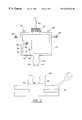
- FIG. 2is a schematic view of a flying latch vehicle of the invention.
- FIG. 3is a schematic view of an underwater operation performed by a linelatch system of the invention.
- the inventionencompasses underwater devices including a linelatch system adapted to be operated from a remote location above the surface of a body of water and utilized for deploying, recovering, servicing, and/or operating various subsurface devices such as toolskids, ROVs, AUVs, pipeline sections (spool pieces), seabed anchors, suction anchors, oil field production packages, and other equipment such as lifting frames, etc.
- various subsurface devicessuch as toolskids, ROVs, AUVs, pipeline sections (spool pieces), seabed anchors, suction anchors, oil field production packages, and other equipment such as lifting frames, etc.
- FIGS. 1A and 1B of the drawingsthe presently preferred embodiment of the invention features a linelatch system 10 including a tether management system 12 connected to a flying latch vehicle 20 by a tether 40 .
- linelatch system 10is shown positioned below the surface of a body of water 8 connected to a surface support vessel 50 floating on the surface of the body of water 8 by an umbilical 45 .
- Tether management system 12can be any device that can reel in or pay out tether 40 .
- Tether management systems suitable for use as tether management system 12are well known in the art and can be purchased from several sources (e.g., from Slingsby Engineering, United Kingdom; All Oceans, United Kingdom; and Perry Tritech, Inc., Jupiter, Fla.). In preferred embodiments, however, tether management system 12 includes an external frame 15 which houses a spool 14 , a spool control switch 16 , and a spool motor 18 .
- Frame 15forms the body of tether management system 12 . It can be any device that can house and/or attach system 12 components such as spool 14 , spool control switch 16 , and spool motor 18 .
- frame 15can take the form of a rigid shell or skeleton-like framework.
- frame 15is a metal cage. A metal cage is preferred because it moves easily through water, and also provides areas for mounting other components of tether management system 12 .
- Spool 14is a component of tether management system 12 that controls the length of tether 40 dispensed from system 12 . It can any device that can reel in, store, and pay out tether 40 .
- pool 14can take the form of a winch about which tether 40 can be wound and unwound.
- spool 14is a rotatable cable drum, where rotation of the drum in one direction causes tether 40 to be payed out of tether management system 12 by unreeling it from around the drum, and rotation of the drum in the other direction causes tether 40 to be taken up by tether management system 12 by reeling it up around the drum.
- Spool motor 18provides power to operate spool 14 .
- Spool motor 18can be any device that is suitable for providing power to spool 14 such that spool 14 can reel in or pay out tether 40 from tether management system 12 .
- spool motor 18can be a motor that causes spool 14 to rotate clockwise or counterclockwise to reel in or pay out tether 40 .
- spool motor 18is an electrically or hydraulically-driven motor.
- Spool control switch 16is a device that controls the action of spool motor 18 . It can be any type of switch which allows an operator of linelatch system 10 to control spool motor 18 . In a preferred form, it is a remotely-operable electrical switch that can be controlled by a technician or pilot on surface support vessel 50 so that motor 18 can power spool 14 operation.
- Tether management system 12can also include a power and data transfer unit 17 between umbilical 45 and tether 40 .
- Unit 17can be any apparatus that can convey power and data between umbilical 45 and tether 40 .
- unit 17takes the form of electrical, hydraulic and/or fiber optic lines connected at one end to umbilical 45 and at the other end to tether 40 .
- umbilical 45Attached to tether management system 12 is umbilical 45 , a long cable-like device used to move linelatch system 10 between a surface platform such as surface support vessel 50 and various subsurface locations via launching and recovery device 48 (e.g., a crane or winch).
- Umbilical 45can be any device that can physically connect linelatch system 10 and a surface platform. Preferably, it is long enough so that linelatch system 10 can be moved between the surface of a body of water and a subsurface location such as the sea bed.
- umbilical 45is negatively buoyant, fairly rigid, and includes an umbilical port capable of transferring power and/or data between tether management system 12 and umbilical 45 (i.e. for conveyance to surface support vessel 50 ).
- the umbilical port of umbilical 45includes two ports.
- the first portis for communicating power for tether management system 12 and umbilical 45 .
- the second portis for communicating data between tether management system 12 and umbilical 45 .
- umbilical 45is a waterproof steel armored cable that houses a conduit for both power (e.g., a copper electrical wire and/or a hydraulic hose) and data communication (e.g., fiber optic cables for receipt and transmission of data).
- Umbilicals suitable for use in the inventionare commercially available from several sources (e.g., NSW, Rochester, and Alcatel).
- tether 40Also attached to tether management system 12 is tether 40 . It has two ends or termini, one end being securely attached to tether management system 12 , the other end being securely attached to tether fastener 21 of flying latch vehicle 20 . While tether 40 can be any device that can physically connect tether management system 12 and flying latch vehicle 20 , it preferably takes the form of a flexible, neutrally buoyant rope-like cable that permits objects attached to it to move relatively freely. In particularly preferred embodiments, tether 40 also includes a power and data communications conduit (e.g., electricity-conducting wire, hydraulic hose, and fiber optic cable) so that power and data can be transferred through it. Tethers suitable for use in the invention are known in the art and are commercially available (e.g., Perry Tritech, Inc.; Southbay; Alcatel; NSW; and JAQUES).
- Tethers suitable for use in the inventionare known in the art and are commercially available (e.g., Perry Tritech, Inc.; Southbay
- flying latch vehicle 20Attached to the terminus of tether 40 opposite tether management system 12 is flying latch vehicle 20 .
- Flying latch vehicle 20is a remotely-operated underwater craft designed to mate with an undersea device for the purpose of transferring power to and/or exchanging data with the undersea device.
- flying latch vehicle 20includes tether fastener 21 , chassis 25 , connector 22 , and propulsion system 28 .
- Chassis 25is a rigid structure that forms the body and/or frame of vehicle 20 .
- Chassis 25can be any device to which various components of vehicle 20 can be attached.
- chassis 25can take the form of a metal skeleton.
- chassis 25is a hollow metal or plastic shell to which the various components of vehicle 20 are attached.
- the interior of chassis 25can be sealed from the external environment so that components included therein can be isolated from exposure to water and pressure.
- components shown affixed to or integrated with chassis 25include tether fastener 21 , connector 22 , propulsion system 28 , and male alignment guides 19 .
- Tether fastener 21connects tether 40 to flying latch vehicle 20 .
- Tether fastener 21can be any suitable device for attaching tether 40 to flying latch vehicle 20 .
- itcan take the form of a mechanical connector adapted to be fastened to a mechanical receptor on the terminus of tether 40 .
- tether fastener 21is the male or female end of bullet-type mechanical fastener (the terminus of tether 40 having the corresponding type of fastener).
- tether fastener 21can also be part of a magnetic or electromagnetic connection system.
- tether fastener 21preferably includes a tether port for conveying power and/or data between tether 40 and flying latch vehicle 20 (e.g., by means of integrated fiber optic and electrical or hydraulic connectors).
- connector 22a structure adapted for detachably connecting receptor 62 of subsurface device 60 so that flying latch vehicle 20 can be securely but reversibly attached to device 60 .
- receptor 62is a structure on subsurface device 60 that is detachably connectable to connector 22 .
- connector 22 and receptor 62usually form a mechanical coupling, they may also connect one another through any other suitable means known in the art (e.g., magnetic or electromagnetic).
- connector 22is a bullet-shaped male-type connector. This type of connector is designed to mechanically mate with a funnel-shaped receptacle such as receptor 62 shown in FIG. 2 .
- the large diameter opening of the funnel-shaped receptor 62 depicted in FIG. 2facilitates alignment of a bullet-shaped connector 22 during the mating process. That is, in this embodiment, if connector 22 was slightly out of alignment with receptor 62 as flying latch vehicle 20 approached subsurface device 60 for mating, the funnel of receptor 62 would automatically align the bullet-shaped portion of connector 22 so that vehicle 20 's motion towards receptor 62 would automatically center connector 22 for proper engagement.
- Connector 22 and receptor 62can also take other forms so long as they are detachably connectable to each other.
- connector 22can take the form of a plurality of prongs arranged in an irregular pattern when receptor 62 takes the form of a plurality of sockets arranged in the same irregular pattern so that connector 22 can connect with receptor 22 in one orientation only.
- connector 22can be a funnel-shaped female type receptacle where receptor 62 is a bullet-shaped male type connector.
- the interaction of connector 22 and receptor 62is utilized to transfer power and data between flying latch vehicle 20 and subsurface device 60 . (See below).
- Propulsion system 28can be any force-producing apparatus that causes undersea movement of flying latch vehicle 20 (i.e., “flying” of vehicle 20 ).
- Preferred devices for use as propulsion system 28are electrically or hydraulically-powered thrusters. Such devices are widely available from commercial suppliers (e.g., Hydrovision Ltd., Aberdeen, Scotland; Innerspace, California; and others).
- flying latch vehicle 20further includes a connector that may include an output port 24 and/or a communications port 26 ; and position control system 30 which may include compass 32 , depth indicator 34 , velocity indicator 36 , and/or video camera 38 .
- Power output port 24can be any device that mediates the underwater transfer of power from flying latch vehicle 20 to another underwater apparatus such as subsurface device 60 .
- port 24physically engages power inlet 64 on subsurface device 60 such that power exits flying latch vehicle 20 from port 24 and enters device 60 through power inlet 64 .
- the power conveyed from power output port 24 to power inlet 64is electrical current or hydraulic power (derived, e.g., from surface support vehicle 50 ) to subsurface device 60 ).
- power output port 24 and power inlet 64form a “wet-mate”-type connector (i.e., an electrical, hydraulic, and/or optical connector designed for mating and demating underwater).
- a “wet-mate”-type connectori.e., an electrical, hydraulic, and/or optical connector designed for mating and demating underwater.
- port 24is integrated into connector 22 and power inlet 64 is integrated with receptor 62 .
- port 24is not integrated with connector 22 but attached at another location on flying latch vehicle 20
- inlet 64is located on device 60 such that it can engage port 26 when vehicle 20 and device 60 connect.
- flying latch vehicle 20can function together as a power transmitter for conveying power from tether 40 (e.g., supplied from surface support vessel 50 , through umbilical 45 and tether management system 12 ) to an underwater apparatus such as subsurface device 60 .
- tether 40e.g., supplied from surface support vessel 50 , through umbilical 45 and tether management system 12
- powercan enter vehicle 20 from tether 40 through tether fastener 21 .
- This powercan then be conveyed from fastener 21 through a power conducting apparatus such as an electricity-conducting wire or a hydraulic hose attached to or housed within chassis 25 into power output port 24 .
- Power output port 24can then transfer the power to the underwater apparatus as described above.
- the power transmitterhas the capacity to transfer more than about 50% (e.g., approximately 50%, 55%, 60%, 65%, 70%, 75%, 80%, 85%, 90%, 95%, 100%) of the power provided to it from an external power source such as surface support vessel 50 (i.e., via umbilical 45 and tether 40 ) to subsurface device 60 .
- Power not conveyed to subsurface device 60 from the external power sourcecan be used to operate various components on flying latch vehicle 20 (e.g., propulsion system 28 and position control system 30 ).
- 20 bhpis used by flying latch vehicle 20 , and 80 bhp used by subsurface device 60 .
- all systems on vehicle 20may be powered down or turned off once the vehicle has mated with subsurface device 60 .
- Communications port 26is a device that physically engages communications acceptor 63 on subsurface device 60 .
- Port 26 and acceptor 63mediate the transfer of data between flying latch vehicle 20 and device 60 .
- communications port 26is a fiber optic cable connector integrated into connector 22
- acceptor 63is another fiber optic connector integrated with receptor 62 in on device 60 .
- the port 26 -acceptor 63 connectioncan also be an electrical connection (e.g., telephone wire) or other type of connection (e.g., magnetic or acoustic).
- the communications port 26 -communications acceptor 63 connection and the power output port 24 -power inlet 64 connectionare integrated into one “wet-mate”-type connector.
- communications port 26is not integrated with connector 22 but attached at another location on flying latch vehicle 20 , and acceptor 63 is located on device 60 such that it can engage port 26 when vehicle 20 and device 60 connect.
- Communications port 26is preferably a two-way communications port that can mediate the transfer of data both from flying latch vehicle 20 to device 60 and from device 60 to vehicle 20 .
- Communications port 26 and acceptor 63can be used to transfer information (e.g., video output, depth, current speed, location information, etc.) from subsurface device 60 to a remotely-located operator (e.g, on surface vessel 50 ) via linelatch 10 and umbilical 45 .
- port 26 and acceptor 63can be used to transfer information (e.g., mission instructions, data for controlling the location and movement of subsurface device 60 , data for controlling mechanical arms and like manipulators on subsurface device 60 , etc.) between a remote location (e.g., on surface support vessel 50 ) and subsurface device 60 .
- Position control system 30is any system or compilation of components that controls underwater movement of flying latch vehicle 20 , and/or provides telemetry data from vehicle 20 to a remotely-located operator.
- telemetry datacan be any data that indicates the location and/or movement of flying latch vehicle 20 (e.g., depth, longitude, latitude, depth, speed, direction), and any related data such as sonar information, pattern recognition information, video output, temperature, current direction and speed, etc.
- position control system 30can include such components as sonar systems, bathymetry devices, thermometers, current sensors, compass 32 , depth indicator 34 , velocity indicator 36 , video camera 38 , etc. These components may be any of those used in conventional underwater vehicles or may be specifically designed for use with linelatch system 10 . Suitable such components are available from several commercial sources.
- position control system 30 for controlling movement of flying latch vehicle 20are preferably those that control propulsion system 28 so that vehicle 20 can be directed to move eastward, westward, northward, southward, up, down, etc. These can, for example, take the form of remotely-operated servos for controlling the direction of thrust produced by propulsion system 28 .
- Other components for controlling movement of flying latch vehicle 20may include buoyancy compensators for controlling the underwater depth of flying latch vehicle 20 and heave compensators (e.g., interposed between tether management system 12 and umbilical 45 ) for reducing wave-induced motion of flying latch vehicle 20 .
- a remotely-positioned operatorcan receive output signals (e.g., telemetry data) and send instruction signals (e.g., data to control propulsion system 28 ) to position control system 30 through the data communication conduit included within umbilical 45 via the data communications conduits within tether management system 12 and tether 40 .
- output signalse.g., telemetry data
- instruction signalse.g., data to control propulsion system 28
- One or more of the components comprising position control system 30can be used as a guidance system for docking flying latch vehicle 20 to subsurface device 60 .
- the guidance systemcould provide a remotely-controlled pilot of vehicle 20 with the aforementioned telemetry data and a video image of receptor 62 on subsurface device 60 such that the pilot could precisely control the movement of vehicle 20 into the docked position with subsurface device 60 using the components of system 30 that control movement of vehicle 20 .
- the guidance systemcould use data such as pattern recognition data to align vehicle 20 with subsurface device 60 and the components of system 30 that control movement of vehicle 20 to automatically maneuver vehicle 20 into the docked position with subsurface device 60 .
- linelatch system 10can be configured in an open position or in a closed configuration.
- linelatch system 10is shown in the open position where tether management system 12 is separated from flying latch vehicle 20 and tether 40 is slack. In this position, to the extent of slack in tether 40 , tether management system 12 and flying latch vehicle 20 are independently moveable from each other.
- FIG. 1Blinelatch system 10 is shown in the closed position. In this configuration, tether management system 12 physically abuts flying latch vehicle 20 and tether 40 is tautly withdrawn into tether management system 12 .
- male alignment guides 19can be affixed to tether management system 12 so that they interlock the female alignment guides 29 affixed to flying latch vehicle 20 .
- Male alignment guides 19can be any type of connector that securely engages female alignment guides 29 such that movement of system 12 is restricted with respect to vehicle 20 , and vice versa.
- linelatch system 10Several other components known in the art of underwater vehicles can be included on linelatch system 10 .
- an on-board auxiliary power supplye.g., batteries, fuel cells, and the like
- an acoustic modemcould be included within linelatch system 10 to provide an additional communications link among, for example, linelatch system 10 , attached subsurface device 60 , and surface support vessel 50 .
- linelatch system 10can be utilized for connecting to, deploying and/or recovering subsurface device 60 to or from a subsurface location (e.g., the seabed).
- linelatch system 10serves as a mechanical link between surface support vessel 50 and subsurface device 60 .
- this methodincludes the steps of deploying linelatch system 10 from surface vessel 50 into body of water 8 ; placing linelatch system 10 in the open position; maneuvering flying latch vehicle 20 to subsurface device 60 ; aligning and mating vehicle 20 with device 60 ; returning linelatch system 10 to the closed position; and hauling system 10 with attached device 60 to the surface of body of water 8 for recovery.
- linelatch system 10can also be used in a method for relaying power and/or data between a device on the surface of body of water 8 (e.g., surface support vessel 50 ) and various undersea objects (e.g., subsurface device 60 ).
- this methodincludes the steps of deploying linelatch system 10 from surface vessel 50 into body of water 8 ; placing linelatch system 10 in the open position; maneuvering flying latch vehicle 20 to subsurface device 60 ; aligning and mating vehicle 20 with device 60 ; transferring power and/or data from vessel 50 to vehicle 20 ; and relaying power and/or data from vehicle 20 to subsurface device 60 .
- linelatch system 10when outfitted with power output port 24 and two way communications port 26 , linelatch system 10 can be lowered to a subsurface location to interface, provide power to, and exchange data with subsurface device 60 (e.g., previously placed on the seabed using cable 64 as shown in FIG. 3 ).
- Linelatch system 10can be deployed from vessel 50 by any method known in the art. For example, linelatch system 10 can be simply thrown over the side of vessel 50 into body of water 8 , or lowered into body of water 8 using a winch. Preferably, however, linelatch system 10 is gently lowered from vessel 50 using launching and recovery device 48 (e.g., a crane) and umbilical 45 .
- launching and recovery device 48e.g., a crane
- linelatch system 10After deployment, linelatch system 10 is placed in the open configuration by playing tether 40 out from tether management system 12 .
- Propulsion system 28 on flying latch vehicle 20can be used to move vehicle 20 away from system 12 to facilitate this process.
- flying latch vehicle 20moves toward subsurface device 60 using propulsion system 28 and position control system 30 until it is aligned for mating with subsurface device 60 . This alignment may be assisted using position control system 30 .
- vehicle 20is moved (e.g., using propulsion system 28 ) a short distance toward device 60 so that connector 22 securely engages receptor 62 .
- the physical connection of connector 22 and receptor 62provides a power and data link between flying latch vehicle 20 and device 60 .
- port 24 and port 26can integrated into connector 22 , and power inlet 64 and acceptor 63 integrated with receptor 62 , such that engagement of connector 22 and receptor 62 also connects port 24 with inlet 64 and port 26 with acceptor 63 .
- port 24 and port 26are not integrated with connector 22 , and inlet 64 and acceptor 63 not integrated with receptor 22 . Rather these components are located at another location on vehicle 20 and device 60 , respectively.
- power transmitted from surface support vessel 50can be transferred via linelatch system 10 to subsurface device 60 .
- datacan be transferred between surface support vessel 50 and subsurface device 60 through linelatch system 10 .
Landscapes
- Engineering & Computer Science (AREA)
- Mechanical Engineering (AREA)
- Ocean & Marine Engineering (AREA)
- Aviation & Aerospace Engineering (AREA)
- Laying Of Electric Cables Or Lines Outside (AREA)
- Electrical Discharge Machining, Electrochemical Machining, And Combined Machining (AREA)
- Testing Or Calibration Of Command Recording Devices (AREA)
- Earth Drilling (AREA)
- Direct Current Feeding And Distribution (AREA)
- Cable Transmission Systems, Equalization Of Radio And Reduction Of Echo (AREA)
- Placing Or Removing Of Piles Or Sheet Piles, Or Accessories Thereof (AREA)
- Glass Compositions (AREA)
- Transition And Organic Metals Composition Catalysts For Addition Polymerization (AREA)
- Unwinding Webs (AREA)
Abstract
Description
Claims (22)
Priority Applications (9)
| Application Number | Priority Date | Filing Date | Title |
|---|---|---|---|
| US09/399,314US6257162B1 (en) | 1999-09-20 | 1999-09-20 | Underwater latch and power supply |
| AT00958932TATE289272T1 (en) | 1999-09-20 | 2000-09-20 | UNDERWATER VEHICLE |
| DE60018196TDE60018196D1 (en) | 1999-09-20 | 2000-09-20 | UNDERWATER VEHICLE |
| EP00958932AEP1218238B1 (en) | 1999-09-20 | 2000-09-20 | submersible vehicle |
| PCT/IB2000/001330WO2001021478A1 (en) | 1999-09-20 | 2000-09-20 | Underwater latch and power supply |
| OA1200200078AOA12025A (en) | 1999-09-20 | 2000-09-20 | Underwater latcha and power supply. |
| AU70338/00AAU777942B2 (en) | 1999-09-20 | 2000-09-20 | Underwater latch and power supply |
| BR0013414-7ABR0013414A (en) | 1999-09-20 | 2000-09-20 | Submersible vehicle and system for underwater operations, and, method of relaying energy from a ship to an underwater device in a body of water. |
| NO20020453ANO318635B1 (en) | 1999-09-20 | 2002-01-29 | Underwater interlocking and power supply. |
Applications Claiming Priority (1)
| Application Number | Priority Date | Filing Date | Title |
|---|---|---|---|
| US09/399,314US6257162B1 (en) | 1999-09-20 | 1999-09-20 | Underwater latch and power supply |
Publications (1)
| Publication Number | Publication Date |
|---|---|
| US6257162B1true US6257162B1 (en) | 2001-07-10 |
Family
ID=23579059
Family Applications (1)
| Application Number | Title | Priority Date | Filing Date |
|---|---|---|---|
| US09/399,314Expired - LifetimeUS6257162B1 (en) | 1999-09-20 | 1999-09-20 | Underwater latch and power supply |
Country Status (9)
| Country | Link |
|---|---|
| US (1) | US6257162B1 (en) |
| EP (1) | EP1218238B1 (en) |
| AT (1) | ATE289272T1 (en) |
| AU (1) | AU777942B2 (en) |
| BR (1) | BR0013414A (en) |
| DE (1) | DE60018196D1 (en) |
| NO (1) | NO318635B1 (en) |
| OA (1) | OA12025A (en) |
| WO (1) | WO2001021478A1 (en) |
Cited By (53)
| Publication number | Priority date | Publication date | Assignee | Title |
|---|---|---|---|---|
| US20030034177A1 (en)* | 2001-08-19 | 2003-02-20 | Chitwood James E. | High power umbilicals for subterranean electric drilling machines and remotely operated vehicles |
| US6588980B2 (en)* | 2001-05-15 | 2003-07-08 | Halliburton Energy Services, Inc. | Underwater cable deployment system and method |
| WO2004070167A1 (en)* | 2003-02-04 | 2004-08-19 | Sensor Highway Limited | Method and system for the use of a distributed temperature system in a subsea well |
| US20040188094A1 (en)* | 2003-03-24 | 2004-09-30 | Michael Piecyk | Wireline subsea metering head and method of use |
| US20040227500A1 (en)* | 2003-05-14 | 2004-11-18 | O'meara Kevan T. | Method and apparatus for branching a single wire power distribution system |
| US20060231264A1 (en)* | 2005-03-11 | 2006-10-19 | Boyce Charles B | Riserless modular subsea well intervention, method and apparatus |
| US20080282776A1 (en)* | 2007-05-17 | 2008-11-20 | Trident Subsea Technologies, Llc | Universal pump platform |
| US20090007835A1 (en)* | 2007-04-17 | 2009-01-08 | Woods Hole Oceanographic Institution | Systems and methods for tethering underwater vehicles |
| US20090281676A1 (en)* | 2008-04-16 | 2009-11-12 | Beavis Russell H | Systems, Apparatus, and Methods for the Management and Control of Remotely Controlled Devices |
| US20100052309A1 (en)* | 2008-08-26 | 2010-03-04 | Oceaneering International, Inc. | Umbilical Bullet Connector |
| US20100085064A1 (en)* | 2008-05-13 | 2010-04-08 | James Bradley Loeb | Universal power and testing platform |
| US20100307760A1 (en)* | 2009-06-04 | 2010-12-09 | Blue Ocean Technologies LLC | Subsea wireline intervention system |
| US20110067619A1 (en)* | 2009-09-22 | 2011-03-24 | Lockheed Martin Corporation | Offboard Connection System |
| US20110093138A1 (en)* | 2008-04-07 | 2011-04-21 | Eni S.P.A. | Combined piloting method of remote operated underwater vehicles, device for its implementation and system using the same |
| US8020505B1 (en) | 2008-03-03 | 2011-09-20 | The United States Of America As Represented By The Secretary Of The Navy | Probe receiver device for recovering surface water vessels |
| US20110240303A1 (en)* | 2008-12-12 | 2011-10-06 | Hallundbaek Joergen | Subsea well intervention module |
| WO2012158958A1 (en)* | 2011-05-18 | 2012-11-22 | Bluefin Robotics Corporation | Fiber optic cable system for underwater remotely operated vehicle |
| US8334744B1 (en)* | 2010-02-05 | 2012-12-18 | Lockheed Martin Company | Tether cable with increased thermal dissipation and method of tethering an underwater vehicle |
| US8515677B1 (en) | 2002-08-15 | 2013-08-20 | Smart Drilling And Completion, Inc. | Methods and apparatus to prevent failures of fiber-reinforced composite materials under compressive stresses caused by fluids and gases invading microfractures in the materials |
| US20130220625A1 (en)* | 2010-04-14 | 2013-08-29 | Anders Billington | Subsea orientation and control system |
| WO2013177164A1 (en)* | 2012-05-24 | 2013-11-28 | Gregg Marine, Inc. | Braided termination for fiber subsea umbilical line |
| CN104114445A (en)* | 2011-11-15 | 2014-10-22 | 萨博赛7有限公司 | Launch and recovery techniques for submersible vehicles and other payloads |
| US20140321236A1 (en)* | 2013-04-25 | 2014-10-30 | Cgg Services Sa | Methods and underwater bases for using autonomous underwater vehicle for marine seismic surveys |
| US20150002092A1 (en)* | 2012-04-11 | 2015-01-01 | Ihi Corporation | Underwater power supply system |
| US20150149114A1 (en)* | 2012-05-30 | 2015-05-28 | Onesubsea Ip Uk Limited | Monitoring Integrity of a Riser Pipe Network |
| US9090315B1 (en) | 2010-11-23 | 2015-07-28 | Piedra—Sombra Corporation, Inc. | Optical energy transfer and conversion system |
| US20150239538A1 (en)* | 2012-11-27 | 2015-08-27 | Fairfield Industries Incorporated D/B/A Fairfieldnodal | Capture and docking apparatus, method, and applications |
| WO2016005955A1 (en)* | 2014-07-10 | 2016-01-14 | Saipem S.P.A. | Underwater vehicle, system and method for performing rescue operations in a body of water |
| US9586699B1 (en) | 1999-08-16 | 2017-03-07 | Smart Drilling And Completion, Inc. | Methods and apparatus for monitoring and fixing holes in composite aircraft |
| US9625361B1 (en) | 2001-08-19 | 2017-04-18 | Smart Drilling And Completion, Inc. | Methods and apparatus to prevent failures of fiber-reinforced composite materials under compressive stresses caused by fluids and gases invading microfractures in the materials |
| US9828822B1 (en)* | 2017-02-27 | 2017-11-28 | Chevron U.S.A. Inc. | BOP and production tree landing assist systems and methods |
| US9850711B2 (en) | 2011-11-23 | 2017-12-26 | Stone Aerospace, Inc. | Autonomous laser-powered vehicle |
| US20180245417A1 (en)* | 2015-09-16 | 2018-08-30 | National Oilwell Varco, L.P. | Subsea Control Pod Deployment and Retrieval Systems and Methods |
| CN108492956A (en)* | 2018-03-27 | 2018-09-04 | 中国船舶科学研究中心(中国船舶重工集团公司第七0二研究所) | A kind of magnetic docking facilities of ROV and power tool library |
| US10081446B2 (en) | 2015-03-11 | 2018-09-25 | William C. Stone | System for emergency crew return and down-mass from orbit |
| US10132155B2 (en)* | 2016-12-02 | 2018-11-20 | Onesubsea Ip Uk Limited | Instrumented subsea flowline jumper connector |
| US20190337601A1 (en)* | 2015-08-25 | 2019-11-07 | Fmc Technologies Do Brasil Ltda | Electric power generating submarine tool |
| US10569849B2 (en) | 2014-12-19 | 2020-02-25 | Stone Aerospace, Inc. | Method of retrieval for autonomous underwater vehicles |
| US20200300055A1 (en)* | 2017-11-17 | 2020-09-24 | Ge Oil & Gas Uk Limited | Auxiliary equipment provision |
| CN111891319A (en)* | 2020-07-15 | 2020-11-06 | 中国科学院沈阳自动化研究所 | Optical fiber management device and method for full-sea autonomous remote control underwater robot |
| CN111924074A (en)* | 2020-08-26 | 2020-11-13 | 兰州乾元生态科技有限公司 | A scalable underwater robot |
| US10987768B2 (en) | 2018-10-26 | 2021-04-27 | Forum Us, Inc. | Torque tool with latch assembly |
| US11040421B2 (en) | 2018-10-26 | 2021-06-22 | Forum Us, Inc. | Torque tool with electric motors |
| RU2759118C1 (en)* | 2020-07-03 | 2021-11-09 | Федеральное государственное бюджетное образовательное учреждение высшего образования "Томский государственный университет систем управления и радиоэлектроники" (ТУСУР) | Power supply device for a remote-controlled uninhabited underwater vehicle with direct current energy transmission via an spc cable |
| US11186962B2 (en)* | 2017-01-30 | 2021-11-30 | Ihc Holland Ie B.V. | System for use with a crane on a surface vessel |
| CN114007936A (en)* | 2019-05-02 | 2022-02-01 | 伊特里克公司 | Ships and cranes for offshore operations involving energy consuming equipment or tools |
| US11346205B2 (en) | 2016-12-02 | 2022-05-31 | Onesubsea Ip Uk Limited | Load and vibration monitoring on a flowline jumper |
| US20220252185A1 (en)* | 2021-02-08 | 2022-08-11 | Deep Down, Inc. | Subsea cable installation and recovery system |
| US11493233B2 (en) | 2016-09-26 | 2022-11-08 | Stone Aerospace, Inc. | Direct high voltage water heater |
| US11505295B2 (en)* | 2017-06-22 | 2022-11-22 | Fulldepth Co., Ltd. | Adapter, electronic device, and method for transporting electronic device |
| US20230191925A1 (en)* | 2020-05-20 | 2023-06-22 | Ipt Technology Gmbh | Device and method for inductively transmitting electrical energy to a watercraft and charging system |
| US12006651B2 (en) | 2018-11-22 | 2024-06-11 | Iqip Holding B.V. | Pile driving system |
| US12206036B2 (en) | 2011-11-23 | 2025-01-21 | Stone Aerospace, Inc. | Power conversion module for use with optical energy transfer and conversion system |
Families Citing this family (13)
| Publication number | Priority date | Publication date | Assignee | Title |
|---|---|---|---|---|
| FR2904288B1 (en)* | 2006-07-26 | 2009-04-24 | Ifremer | INSTALLATION AND METHOD FOR RECOVERING A SUBMARINE OR MARINE |
| FR2963924B1 (en)* | 2010-08-18 | 2012-09-14 | Ifremer | DEVICE FOR RECOVERING A MARINE OR SUBMARINE DEVICE |
| RU2438914C1 (en)* | 2010-09-27 | 2012-01-10 | Общество с ограниченной ответственностью "Океан-Инвест СПб" | Immersible transformable platform and robotic complex for underwater jobs |
| RU2468959C1 (en)* | 2011-05-25 | 2012-12-10 | Общество с ограниченной ответственностью "Океан-Инвест СПб" | Submersible robotised complex for measurements and repair of waterworks |
| RU2544045C1 (en)* | 2013-09-05 | 2015-03-10 | Российская Федерация, От Имени Которой Выступает Министерство Промышленности И Торговли Российской Федерации | System for repair and servicing of underwater production complexes in ice conditions |
| GB2520010B (en) | 2013-11-05 | 2016-06-01 | Subsea 7 Ltd | Tools and Sensors Deployed by Unmanned Underwater Vehicles |
| RU2563074C1 (en)* | 2014-08-13 | 2015-09-20 | Открытое акционерное общество "Государственный научно-исследовательский навигационно-гидрографический институт" (ОАО "ГНИНГИ") | Underwater robotic complex |
| FR3055607B1 (en)* | 2016-09-05 | 2018-08-31 | Forssea Robotics | COMMUNICATION AND TRANSFER SYSTEM BETWEEN AN EMERGING OBJECT AND AN IMMERSE OBJECT, AN ASSEMBLY COMPRISING AN EMERGING OBJECT, AN IMMERSE OBJECT AND METHOD OF COMMUNICATION AND TRANSFER BETWEEN THE OBJECT |
| WO2018091574A1 (en)* | 2016-11-17 | 2018-05-24 | Metas As | Subsea sensor system using maneuverable tool for rov free installation and maintenance of subsea sensor carriers |
| FR3087748B1 (en)* | 2018-10-25 | 2021-05-28 | Forssea Robotics | DEPLOYMENT AND LIFTING OF LOADS USING AN UNDERWATER VEHICLE |
| RU2753984C1 (en)* | 2020-06-04 | 2021-08-25 | Федеральное государственное казенное военное образовательное учреждение высшего образования "Военный учебно-научный центр Военно-Морского Флота "Военно-морская академия им. Адмирала Флота Советского Союза Н.Г. Кузнецова" | Autonomous deep-water lighting apparatus |
| RU206765U1 (en)* | 2021-04-22 | 2021-09-28 | Федеральное государственное бюджетное образовательное учреждение высшего образования "Казанский национальный исследовательский технический университет им. А.Н. Туполева - КАИ" | A controlled device for conducting search, rescue, and monitoring operations under water |
| GB202202205D0 (en)* | 2022-02-18 | 2022-04-06 | Aquaterra Energy Ltd | A tethering system for a blow-out preventer |
Citations (9)
| Publication number | Priority date | Publication date | Assignee | Title |
|---|---|---|---|---|
| US3099316A (en) | 1960-04-25 | 1963-07-30 | Shell Oil Co | Underwater wellhead apparatus and method |
| US3921500A (en) | 1974-06-10 | 1975-11-25 | Chevron Res | System for operating hydraulic apparatus |
| US4010619A (en)* | 1976-05-24 | 1977-03-08 | The United States Of America As Represented By The Secretary Of The Navy | Remote unmanned work system (RUWS) electromechanical cable system |
| US4502407A (en) | 1982-04-12 | 1985-03-05 | Shell Oil Company | Method and apparatus for cleaning, viewing and documenting the condition of weldments on offshore platforms |
| GB2160156A (en) | 1984-06-14 | 1985-12-18 | Seametrix Limited | Launching structures for remotely-operated submersible vehicles |
| US4706119A (en) | 1985-09-11 | 1987-11-10 | Shell Offshore Inc. | Camera vision axis inclination indication apparatus |
| GB2190969A (en) | 1986-04-14 | 1987-12-02 | Oceaneering Int Inc | Hydraulic connector |
| US4732215A (en) | 1985-05-04 | 1988-03-22 | British Petroleum Company Plc | Subsea oil production system |
| GB2210838A (en) | 1987-10-10 | 1989-06-21 | Ferranti Int Signal | Subsea working arrangement including submersible vehicle docking arrangement and garage |
- 1999
- 1999-09-20USUS09/399,314patent/US6257162B1/ennot_activeExpired - Lifetime
- 2000
- 2000-09-20BRBR0013414-7Apatent/BR0013414A/ennot_activeIP Right Cessation
- 2000-09-20ATAT00958932Tpatent/ATE289272T1/ennot_activeIP Right Cessation
- 2000-09-20EPEP00958932Apatent/EP1218238B1/ennot_activeExpired - Lifetime
- 2000-09-20AUAU70338/00Apatent/AU777942B2/ennot_activeCeased
- 2000-09-20OAOA1200200078Apatent/OA12025A/enunknown
- 2000-09-20WOPCT/IB2000/001330patent/WO2001021478A1/enactiveIP Right Grant
- 2000-09-20DEDE60018196Tpatent/DE60018196D1/ennot_activeExpired - Lifetime
- 2002
- 2002-01-29NONO20020453Apatent/NO318635B1/ennot_activeIP Right Cessation
Patent Citations (9)
| Publication number | Priority date | Publication date | Assignee | Title |
|---|---|---|---|---|
| US3099316A (en) | 1960-04-25 | 1963-07-30 | Shell Oil Co | Underwater wellhead apparatus and method |
| US3921500A (en) | 1974-06-10 | 1975-11-25 | Chevron Res | System for operating hydraulic apparatus |
| US4010619A (en)* | 1976-05-24 | 1977-03-08 | The United States Of America As Represented By The Secretary Of The Navy | Remote unmanned work system (RUWS) electromechanical cable system |
| US4502407A (en) | 1982-04-12 | 1985-03-05 | Shell Oil Company | Method and apparatus for cleaning, viewing and documenting the condition of weldments on offshore platforms |
| GB2160156A (en) | 1984-06-14 | 1985-12-18 | Seametrix Limited | Launching structures for remotely-operated submersible vehicles |
| US4732215A (en) | 1985-05-04 | 1988-03-22 | British Petroleum Company Plc | Subsea oil production system |
| US4706119A (en) | 1985-09-11 | 1987-11-10 | Shell Offshore Inc. | Camera vision axis inclination indication apparatus |
| GB2190969A (en) | 1986-04-14 | 1987-12-02 | Oceaneering Int Inc | Hydraulic connector |
| GB2210838A (en) | 1987-10-10 | 1989-06-21 | Ferranti Int Signal | Subsea working arrangement including submersible vehicle docking arrangement and garage |
Non-Patent Citations (7)
| Title |
|---|
| "Autonomous Underwater Vehicles (AUVs)", http://www.ise.bc.ca/auv.html, (downloaded Aug. 31, 1999). |
| "AUVs-this is what the oil industry wants", International Ocean Systems Design, vol. 3, No. 4, pp. 12-15 (Jul./Aug. 1999). |
| "French group developing production umbilical AUV", Offshore, pp. 66 and 158 (Oct. 1998). |
| "Hybrid Wet-Mate Connectors: "Writing the Next Chapter'", Dr. James Cairns, Sea Technology. |
| "Remotely Operated Vehicles (ROVs)", http://www.ise.bc.ca/rov.html, (downloaded Aug. 31, 1999). |
| "AUVs—this is what the oil industry wants", International Ocean Systems Design, vol. 3, No. 4, pp. 12-15 (Jul./Aug. 1999). |
| "Hybrid Wet-Mate Connectors: ‘Writing the Next Chapter’", Dr. James Cairns, Sea Technology. |
Cited By (97)
| Publication number | Priority date | Publication date | Assignee | Title |
|---|---|---|---|---|
| US9586699B1 (en) | 1999-08-16 | 2017-03-07 | Smart Drilling And Completion, Inc. | Methods and apparatus for monitoring and fixing holes in composite aircraft |
| US6588980B2 (en)* | 2001-05-15 | 2003-07-08 | Halliburton Energy Services, Inc. | Underwater cable deployment system and method |
| US20030034177A1 (en)* | 2001-08-19 | 2003-02-20 | Chitwood James E. | High power umbilicals for subterranean electric drilling machines and remotely operated vehicles |
| US6857486B2 (en)* | 2001-08-19 | 2005-02-22 | Smart Drilling And Completion, Inc. | High power umbilicals for subterranean electric drilling machines and remotely operated vehicles |
| EP1436482A4 (en)* | 2001-08-19 | 2005-08-31 | Smart Drilling And Completion | High power umbilicals for subterranean electric drilling machines and remotely operated vehicles |
| US9625361B1 (en) | 2001-08-19 | 2017-04-18 | Smart Drilling And Completion, Inc. | Methods and apparatus to prevent failures of fiber-reinforced composite materials under compressive stresses caused by fluids and gases invading microfractures in the materials |
| US8515677B1 (en) | 2002-08-15 | 2013-08-20 | Smart Drilling And Completion, Inc. | Methods and apparatus to prevent failures of fiber-reinforced composite materials under compressive stresses caused by fluids and gases invading microfractures in the materials |
| WO2004070167A1 (en)* | 2003-02-04 | 2004-08-19 | Sensor Highway Limited | Method and system for the use of a distributed temperature system in a subsea well |
| NO339526B1 (en)* | 2003-02-04 | 2016-12-27 | Schlumberger Technology Corp | Method and system for the use of a distributed temperature system in an underwater well. |
| GB2398444B (en)* | 2003-02-04 | 2005-08-17 | Sensor Highway Ltd | Method and system for the use of a distributed temperature system in a subsea well |
| US20040188094A1 (en)* | 2003-03-24 | 2004-09-30 | Michael Piecyk | Wireline subsea metering head and method of use |
| US7000903B2 (en) | 2003-03-24 | 2006-02-21 | Oceaneering International, Inc. | Wireline subsea metering head and method of use |
| US6838865B2 (en)* | 2003-05-14 | 2005-01-04 | Northrop Grumman Corporation | Method and apparatus for branching a single wire power distribution system |
| US20040227500A1 (en)* | 2003-05-14 | 2004-11-18 | O'meara Kevan T. | Method and apparatus for branching a single wire power distribution system |
| US7891429B2 (en)* | 2005-03-11 | 2011-02-22 | Saipem America Inc. | Riserless modular subsea well intervention, method and apparatus |
| US20060231264A1 (en)* | 2005-03-11 | 2006-10-19 | Boyce Charles B | Riserless modular subsea well intervention, method and apparatus |
| US7621229B2 (en)* | 2007-04-17 | 2009-11-24 | Woods Hole Oceanographic Institution | Systems and methods for tethering underwater vehicles |
| US20090007835A1 (en)* | 2007-04-17 | 2009-01-08 | Woods Hole Oceanographic Institution | Systems and methods for tethering underwater vehicles |
| US8240952B2 (en)* | 2007-05-17 | 2012-08-14 | Trident Subsea Technologies, Llc | Universal pump platform |
| US20080282776A1 (en)* | 2007-05-17 | 2008-11-20 | Trident Subsea Technologies, Llc | Universal pump platform |
| US8020505B1 (en) | 2008-03-03 | 2011-09-20 | The United States Of America As Represented By The Secretary Of The Navy | Probe receiver device for recovering surface water vessels |
| US8418765B2 (en) | 2008-04-07 | 2013-04-16 | Eni S.P.A. | Combined piloting method of remote operated underwater vehicles, device for its implementation and system using the same |
| US20110093138A1 (en)* | 2008-04-07 | 2011-04-21 | Eni S.P.A. | Combined piloting method of remote operated underwater vehicles, device for its implementation and system using the same |
| US20090281676A1 (en)* | 2008-04-16 | 2009-11-12 | Beavis Russell H | Systems, Apparatus, and Methods for the Management and Control of Remotely Controlled Devices |
| US10895898B2 (en)* | 2008-04-16 | 2021-01-19 | Deka Products Limited Partnership | Management of remotely controlled devices |
| US12086003B2 (en) | 2008-04-16 | 2024-09-10 | Deka Products Limited Partnership | Management of remotely controlled devices |
| US20100085064A1 (en)* | 2008-05-13 | 2010-04-08 | James Bradley Loeb | Universal power and testing platform |
| US8240191B2 (en)* | 2008-05-13 | 2012-08-14 | Trident Subsea Technologies, Llc | Universal power and testing platform |
| US20100052309A1 (en)* | 2008-08-26 | 2010-03-04 | Oceaneering International, Inc. | Umbilical Bullet Connector |
| US7906727B2 (en) | 2008-08-26 | 2011-03-15 | Oceaneering International, Inc. | Umbilical bullet connector |
| US20110240303A1 (en)* | 2008-12-12 | 2011-10-06 | Hallundbaek Joergen | Subsea well intervention module |
| US20100307760A1 (en)* | 2009-06-04 | 2010-12-09 | Blue Ocean Technologies LLC | Subsea wireline intervention system |
| US20110067619A1 (en)* | 2009-09-22 | 2011-03-24 | Lockheed Martin Corporation | Offboard Connection System |
| US8146527B2 (en) | 2009-09-22 | 2012-04-03 | Lockheed Martin Corporation | Offboard connection system |
| US8334744B1 (en)* | 2010-02-05 | 2012-12-18 | Lockheed Martin Company | Tether cable with increased thermal dissipation and method of tethering an underwater vehicle |
| US20130220625A1 (en)* | 2010-04-14 | 2013-08-29 | Anders Billington | Subsea orientation and control system |
| US9010431B2 (en)* | 2010-04-14 | 2015-04-21 | Aker Subsea As | Subsea orientation and control system |
| US8616805B2 (en) | 2010-05-18 | 2013-12-31 | Bluefin Robotics, Corporation | Optical fiber management system and method |
| US10739524B2 (en)* | 2010-11-23 | 2020-08-11 | Stone Aerospace, Inc. | Optical energy transfer and conversion system for planetary rover having axially configured fiber spooler mounted thereon |
| US10261263B2 (en) | 2010-11-23 | 2019-04-16 | Stone Aerospace, Inc. | Non-line-of-sight optical power transfer system for launching a spacecraft into low earth orbit |
| US10739522B2 (en)* | 2010-11-23 | 2020-08-11 | Stone Aerospace, Inc. | Optical energy transfer and conversion system for remotely operated vehicle having axially configured fiber spooler mounted thereon |
| US10705296B2 (en)* | 2010-11-23 | 2020-07-07 | Stone Aerospace, Inc. | Optical energy transfer and conversion system for remotely operated vehicle having drum configured fiber spooler mounted thereon |
| US10578808B2 (en) | 2010-11-23 | 2020-03-03 | Stone Aerospace, Inc. | Fiber optic rotary joint for use in an optical energy transfer and conversion system |
| US9090315B1 (en) | 2010-11-23 | 2015-07-28 | Piedra—Sombra Corporation, Inc. | Optical energy transfer and conversion system |
| US10739525B2 (en)* | 2010-11-23 | 2020-08-11 | Stone Aerospace, Inc. | Optical energy transfer and conversion system for autonomous underwater vehicle having drum configured fiber spooler mounted thereon |
| US10739523B2 (en)* | 2010-11-23 | 2020-08-11 | Stone Aerospace, Inc. | Optical energy transfer and conversion system for unmanned aerial vehicle having axially configured fiber spooler mounted thereon |
| US10782482B2 (en)* | 2010-11-23 | 2020-09-22 | Stone Aerospace, Inc. | Optical energy transfer and conversion system for unmanned aerial vehicle having drum configured fiber spooler mounted thereon |
| US10852485B2 (en)* | 2010-11-23 | 2020-12-01 | Stone Aerospace, Inc. | Optical energy transfer and conversion system for planetary rover having drum configured fiber spooler mounted thereon |
| US20180136405A1 (en)* | 2010-11-23 | 2018-05-17 | Stone Aerospace, Inc. | Optical Energy Transfer and Conversion System for Autonomous Underwater Vehicle having Drum Configured Fiber Spooler Mounted Thereon |
| US20180136403A1 (en)* | 2010-11-23 | 2018-05-17 | Stone Aerospace, Inc. | Optical Energy Transfer and Conversion System for Unmanned Aerial Vehicle having Axially Configured Fiber Spooler Mounted Thereon |
| US20180136402A1 (en)* | 2010-11-23 | 2018-05-17 | Stone Aerospace, Inc. | Optical Energy Transfer and Conversion System for Remotely Operated Vehicle having Axially Configured Fiber Spooler Mounted Thereon |
| US20180136407A1 (en)* | 2010-11-23 | 2018-05-17 | Stone Aerospace, Inc. | Optical Energy Transfer and Conversion System for Unmanned Aerial Vehicle having Drum Configured Fiber Spooler Mounted Thereon |
| WO2012158958A1 (en)* | 2011-05-18 | 2012-11-22 | Bluefin Robotics Corporation | Fiber optic cable system for underwater remotely operated vehicle |
| CN104114445A (en)* | 2011-11-15 | 2014-10-22 | 萨博赛7有限公司 | Launch and recovery techniques for submersible vehicles and other payloads |
| US9387911B2 (en)* | 2011-11-15 | 2016-07-12 | Subsea 7 Limited | Launch and recovery techniques for submersible vehicles and other payloads |
| US9850711B2 (en) | 2011-11-23 | 2017-12-26 | Stone Aerospace, Inc. | Autonomous laser-powered vehicle |
| US12206036B2 (en) | 2011-11-23 | 2025-01-21 | Stone Aerospace, Inc. | Power conversion module for use with optical energy transfer and conversion system |
| US9467005B2 (en)* | 2012-04-11 | 2016-10-11 | Ihi Corporation | Underwater power supply system |
| US20150002092A1 (en)* | 2012-04-11 | 2015-01-01 | Ihi Corporation | Underwater power supply system |
| AU2013266434B2 (en)* | 2012-05-24 | 2015-12-17 | Gregg Drilling, LLC | Braided termination for fiber subsea umbilical line |
| WO2013177164A1 (en)* | 2012-05-24 | 2013-11-28 | Gregg Marine, Inc. | Braided termination for fiber subsea umbilical line |
| US20150149114A1 (en)* | 2012-05-30 | 2015-05-28 | Onesubsea Ip Uk Limited | Monitoring Integrity of a Riser Pipe Network |
| US10378331B2 (en)* | 2012-05-30 | 2019-08-13 | Onesubsea Ip Uk Limited | Monitoring integrity of a riser pipe network |
| US9415848B2 (en)* | 2012-11-27 | 2016-08-16 | Fairfield Industries Incorporated | Capture and docking apparatus, method, and applications |
| US9487280B2 (en)* | 2012-11-27 | 2016-11-08 | Fairfield Industries Incorporated | Capture and docking apparatus, method, and applications |
| US20150284060A1 (en)* | 2012-11-27 | 2015-10-08 | Farifield Industries Incorporated | Capture and docking apparatus, method, and applications |
| US20150239538A1 (en)* | 2012-11-27 | 2015-08-27 | Fairfield Industries Incorporated D/B/A Fairfieldnodal | Capture and docking apparatus, method, and applications |
| US10017232B2 (en) | 2013-04-25 | 2018-07-10 | Cgg Services Sas | Methods and underwater bases for using autonomous underwater vehicle for marine seismic surveys |
| US9321514B2 (en)* | 2013-04-25 | 2016-04-26 | Cgg Services Sa | Methods and underwater bases for using autonomous underwater vehicle for marine seismic surveys |
| US20140321236A1 (en)* | 2013-04-25 | 2014-10-30 | Cgg Services Sa | Methods and underwater bases for using autonomous underwater vehicle for marine seismic surveys |
| WO2016005955A1 (en)* | 2014-07-10 | 2016-01-14 | Saipem S.P.A. | Underwater vehicle, system and method for performing rescue operations in a body of water |
| US10569849B2 (en) | 2014-12-19 | 2020-02-25 | Stone Aerospace, Inc. | Method of retrieval for autonomous underwater vehicles |
| US10081446B2 (en) | 2015-03-11 | 2018-09-25 | William C. Stone | System for emergency crew return and down-mass from orbit |
| US20190337601A1 (en)* | 2015-08-25 | 2019-11-07 | Fmc Technologies Do Brasil Ltda | Electric power generating submarine tool |
| US10814948B2 (en)* | 2015-08-25 | 2020-10-27 | Fmc Technologies Do Brasil Ltda | Electric power generating submarine tool |
| US20180245417A1 (en)* | 2015-09-16 | 2018-08-30 | National Oilwell Varco, L.P. | Subsea Control Pod Deployment and Retrieval Systems and Methods |
| US10648294B2 (en)* | 2015-09-16 | 2020-05-12 | National Oilwell Varco, L.P. | Subsea control pod deployment and retrieval systems and methods |
| US11493233B2 (en) | 2016-09-26 | 2022-11-08 | Stone Aerospace, Inc. | Direct high voltage water heater |
| US10132155B2 (en)* | 2016-12-02 | 2018-11-20 | Onesubsea Ip Uk Limited | Instrumented subsea flowline jumper connector |
| US11346205B2 (en) | 2016-12-02 | 2022-05-31 | Onesubsea Ip Uk Limited | Load and vibration monitoring on a flowline jumper |
| US11186962B2 (en)* | 2017-01-30 | 2021-11-30 | Ihc Holland Ie B.V. | System for use with a crane on a surface vessel |
| US9828822B1 (en)* | 2017-02-27 | 2017-11-28 | Chevron U.S.A. Inc. | BOP and production tree landing assist systems and methods |
| US20230024776A1 (en)* | 2017-06-22 | 2023-01-26 | Fulldepth Co., Ltd. | Adapter, electronic device, and method for transporting electronic device |
| US12116095B2 (en)* | 2017-06-22 | 2024-10-15 | Fulldepth Co., Ltd. | Adapter, electronic device, and method for transporting electronic device |
| US11505295B2 (en)* | 2017-06-22 | 2022-11-22 | Fulldepth Co., Ltd. | Adapter, electronic device, and method for transporting electronic device |
| US20200300055A1 (en)* | 2017-11-17 | 2020-09-24 | Ge Oil & Gas Uk Limited | Auxiliary equipment provision |
| CN108492956A (en)* | 2018-03-27 | 2018-09-04 | 中国船舶科学研究中心(中国船舶重工集团公司第七0二研究所) | A kind of magnetic docking facilities of ROV and power tool library |
| US10987768B2 (en) | 2018-10-26 | 2021-04-27 | Forum Us, Inc. | Torque tool with latch assembly |
| US11040421B2 (en) | 2018-10-26 | 2021-06-22 | Forum Us, Inc. | Torque tool with electric motors |
| US12006651B2 (en) | 2018-11-22 | 2024-06-11 | Iqip Holding B.V. | Pile driving system |
| CN114007936B (en)* | 2019-05-02 | 2023-12-12 | 伊特里克公司 | Ship and crane for offshore operations involving energy consuming equipment or tools |
| CN114007936A (en)* | 2019-05-02 | 2022-02-01 | 伊特里克公司 | Ships and cranes for offshore operations involving energy consuming equipment or tools |
| US20230191925A1 (en)* | 2020-05-20 | 2023-06-22 | Ipt Technology Gmbh | Device and method for inductively transmitting electrical energy to a watercraft and charging system |
| RU2759118C1 (en)* | 2020-07-03 | 2021-11-09 | Федеральное государственное бюджетное образовательное учреждение высшего образования "Томский государственный университет систем управления и радиоэлектроники" (ТУСУР) | Power supply device for a remote-controlled uninhabited underwater vehicle with direct current energy transmission via an spc cable |
| CN111891319A (en)* | 2020-07-15 | 2020-11-06 | 中国科学院沈阳自动化研究所 | Optical fiber management device and method for full-sea autonomous remote control underwater robot |
| CN111924074A (en)* | 2020-08-26 | 2020-11-13 | 兰州乾元生态科技有限公司 | A scalable underwater robot |
| US20220252185A1 (en)* | 2021-02-08 | 2022-08-11 | Deep Down, Inc. | Subsea cable installation and recovery system |
Also Published As
| Publication number | Publication date |
|---|---|
| NO318635B1 (en) | 2005-04-18 |
| BR0013414A (en) | 2004-03-30 |
| AU7033800A (en) | 2001-04-24 |
| AU777942B2 (en) | 2004-11-04 |
| DE60018196D1 (en) | 2005-03-24 |
| WO2001021478A1 (en) | 2001-03-29 |
| NO20020453D0 (en) | 2002-01-29 |
| EP1218238B1 (en) | 2005-02-16 |
| EP1218238A1 (en) | 2002-07-03 |
| ATE289272T1 (en) | 2005-03-15 |
| NO20020453L (en) | 2002-05-15 |
| OA12025A (en) | 2006-04-24 |
Similar Documents
| Publication | Publication Date | Title |
|---|---|---|
| US6257162B1 (en) | Underwater latch and power supply | |
| US6223675B1 (en) | Underwater power and data relay | |
| US6167831B1 (en) | Underwater vehicle | |
| US6390012B1 (en) | Apparatus and method for deploying, recovering, servicing, and operating an autonomous underwater vehicle | |
| AU2009324302B2 (en) | Subsea well intervention module | |
| US9145761B2 (en) | Subsea well intervention module | |
| US11845521B2 (en) | Marine structure comprising a launch and recovery system | |
| Kyo et al. | The sea trial of" KAIKO", the full ocean depth research ROV | |
| Yoshida et al. | A deepest depth ROV for sediment sampling and its sea trial result | |
| KR101422699B1 (en) | Underwater station and underwater vehicle underwater vehicle management system | |
| Rigaud et al. | " New methods for deep sea intervention on benthic laboratories". DESIBEL project. Final results, comparisons of concepts and at sea validation | |
| JPS6037393A (en) | Undersea/undersea work robot system | |
| Nakajoh et al. | 7000m Operable Deep-Sea ROV System,“KAIKO7000” | |
| Manecius Selvakumar et al. | Technology tool for deep ocean exploration–Remotely Operated Vehicle | |
| Shepherd et al. | Observatory cable laying system | |
| Okamura | Development of unmanned submersibles for underwater operations in japan | |
| Yoshida et al. | The Two-stage ROV to the Oceans’ Deepest Depth | |
| Conway | ROV Mantis: A dual-purpose underwater vehicle | |
| Subramanian et al. | Technology Tool For Deep Ocean Exploration¿ Remotely Operated Vehicle | |
| Bell | Deep sea salvage of flight recorders |
Legal Events
| Date | Code | Title | Description |
|---|---|---|---|
| AS | Assignment | Owner name:COFLEXIP STENA OFFSHORE, S.A., FRANCE Free format text:ASSIGNMENT OF ASSIGNORS INTEREST;ASSIGNORS:WATT, ANDREW M.;LEATT, ALLEN F.;MACKINNON, CALUM;REEL/FRAME:010511/0656;SIGNING DATES FROM 19991212 TO 19991213 | |
| STCF | Information on status: patent grant | Free format text:PATENTED CASE | |
| AS | Assignment | Owner name:COFLEXIP, S.A., FRANCE Free format text:CORRECTIVE ASSIGNMENT TO CORRECT THE NAME OF THE ASSIGNEE FILED ON 12-27-99 RECORDED AT REEL 010511, FRAME 0656;ASSIGNORS:WATT, ANDREW M.;LEATT, ALLEN F.;MACKINNON, CALUM;REEL/FRAME:012525/0530;SIGNING DATES FROM 19991212 TO 19991213 | |
| FPAY | Fee payment | Year of fee payment:4 | |
| AS | Assignment | Owner name:TECHNIP FRANCE, FRANCE Free format text:NUNC PRO TUNC ASSIGNMENT;ASSIGNOR:TECHNIP OFFSHORE INTERNATIONAL, S.A.;REEL/FRAME:018861/0087 Effective date:20070202 Owner name:PERRY SLINGSBY SYSTEMS INC., TEXAS Free format text:ASSIGNMENT OF ASSIGNORS INTEREST;ASSIGNOR:TECHNIP FRANCE;REEL/FRAME:018861/0095 Effective date:20070201 Owner name:TECHNIP OFFSHORE INTERNATIONAL, S.A., FRANCE Free format text:NUNC PRO TUNC ASSIGNMENT;ASSIGNOR:COFLEXIP, S.A.;REEL/FRAME:018861/0064 Effective date:20070202 | |
| FEPP | Fee payment procedure | Free format text:PAT HOLDER CLAIMS SMALL ENTITY STATUS, ENTITY STATUS SET TO SMALL (ORIGINAL EVENT CODE: LTOS); ENTITY STATUS OF PATENT OWNER: LARGE ENTITY | |
| FPAY | Fee payment | Year of fee payment:8 | |
| AS | Assignment | Owner name:WELLS FARGO BANK, NATIONAL ASSOCIATION, AS ADMINIS Free format text:SECURITY AGREEMENT;ASSIGNORS:PERRY SLINGSBY SYSTEMS, INC.;FORUM ENERGY TECHNOLOGIES, INC.;REEL/FRAME:024804/0573 Effective date:20100802 | |
| AS | Assignment | Owner name:TGH (US) INC., TEXAS Free format text:MERGER;ASSIGNOR:PERRY SLINGSBY SYSTEMS, INC.;REEL/FRAME:026397/0400 Effective date:20101221 | |
| FEPP | Fee payment procedure | Free format text:PAT HOLDER NO LONGER CLAIMS SMALL ENTITY STATUS, ENTITY STATUS SET TO UNDISCOUNTED (ORIGINAL EVENT CODE: STOL); ENTITY STATUS OF PATENT OWNER: LARGE ENTITY | |
| FPAY | Fee payment | Year of fee payment:12 | |
| AS | Assignment | Owner name:WELLS FARGO BANK, NATIONAL ASSOCIATION, NORTH CAROLINA Free format text:SECURITY INTEREST;ASSIGNORS:FORUM ENERGY TECHNOLOGIES, INC.;FORUM CANADA ULC;REEL/FRAME:044635/0355 Effective date:20171030 Owner name:WELLS FARGO BANK, NATIONAL ASSOCIATION, NORTH CARO Free format text:SECURITY INTEREST;ASSIGNORS:FORUM ENERGY TECHNOLOGIES, INC.;FORUM CANADA ULC;REEL/FRAME:044635/0355 Effective date:20171030 | |
| AS | Assignment | Owner name:WELLS FARGO BANK, NATIONAL ASSOCIATION, NORTH CAROLINA Free format text:SECURITY INTEREST;ASSIGNORS:FORUM ENERGY TECHNOLOGIES, INC.;FORUM CANADA ULC;REEL/FRAME:044812/0161 Effective date:20171030 Owner name:WELLS FARGO BANK, NATIONAL ASSOCIATION, NORTH CARO Free format text:SECURITY INTEREST;ASSIGNORS:FORUM ENERGY TECHNOLOGIES, INC.;FORUM CANADA ULC;REEL/FRAME:044812/0161 Effective date:20171030 | |
| AS | Assignment | Owner name:FORUM US, INC., TEXAS Free format text:MERGER;ASSIGNOR:TGH (US) INC.;REEL/FRAME:047308/0734 Effective date:20171231 |