US6256853B1 - Crimping die employing powered chuck - Google Patents
Crimping die employing powered chuckDownload PDFInfo
- Publication number
- US6256853B1 US6256853B1US09/495,528US49552800AUS6256853B1US 6256853 B1US6256853 B1US 6256853B1US 49552800 AUS49552800 AUS 49552800AUS 6256853 B1US6256853 B1US 6256853B1
- Authority
- US
- United States
- Prior art keywords
- die
- jaws
- powered
- forming
- cavity
- Prior art date
- Legal status (The legal status is an assumption and is not a legal conclusion. Google has not performed a legal analysis and makes no representation as to the accuracy of the status listed.)
- Expired - Lifetime
Links
- 238000002788crimpingMethods0.000titleclaimsabstractdescription32
- 239000012530fluidSubstances0.000claimsdescription10
- 238000000034methodMethods0.000claimsdescription9
- 239000002184metalSubstances0.000claimsdescription5
- 238000005452bendingMethods0.000claims2
- 238000004080punchingMethods0.000claims2
- 239000000314lubricantSubstances0.000description3
- 230000003466anti-cipated effectEffects0.000description2
- 238000011109contaminationMethods0.000description2
- 239000012528membraneSubstances0.000description2
- 238000012986modificationMethods0.000description2
- 230000004048modificationEffects0.000description2
- 230000002093peripheral effectEffects0.000description2
- 229910000831SteelInorganic materials0.000description1
- 229910001315Tool steelInorganic materials0.000description1
- 238000004026adhesive bondingMethods0.000description1
- 238000005253claddingMethods0.000description1
- 238000005461lubricationMethods0.000description1
- 238000004519manufacturing processMethods0.000description1
- 230000000284resting effectEffects0.000description1
- 230000000630rising effectEffects0.000description1
- 239000010959steelSubstances0.000description1
- 238000003466weldingMethods0.000description1
Images


Classifications
- H—ELECTRICITY
- H01—ELECTRIC ELEMENTS
- H01M—PROCESSES OR MEANS, e.g. BATTERIES, FOR THE DIRECT CONVERSION OF CHEMICAL ENERGY INTO ELECTRICAL ENERGY
- H01M6/00—Primary cells; Manufacture thereof
- H01M6/005—Devices for making primary cells
- B—PERFORMING OPERATIONS; TRANSPORTING
- B21—MECHANICAL METAL-WORKING WITHOUT ESSENTIALLY REMOVING MATERIAL; PUNCHING METAL
- B21D—WORKING OR PROCESSING OF SHEET METAL OR METAL TUBES, RODS OR PROFILES WITHOUT ESSENTIALLY REMOVING MATERIAL; PUNCHING METAL
- B21D39/00—Application of procedures in order to connect objects or parts, e.g. coating with sheet metal otherwise than by plating; Tube expanders
- B21D39/04—Application of procedures in order to connect objects or parts, e.g. coating with sheet metal otherwise than by plating; Tube expanders of tubes with tubes; of tubes with rods
- B21D39/048—Application of procedures in order to connect objects or parts, e.g. coating with sheet metal otherwise than by plating; Tube expanders of tubes with tubes; of tubes with rods using presses for radially crimping tubular elements
- H—ELECTRICITY
- H01—ELECTRIC ELEMENTS
- H01M—PROCESSES OR MEANS, e.g. BATTERIES, FOR THE DIRECT CONVERSION OF CHEMICAL ENERGY INTO ELECTRICAL ENERGY
- H01M50/00—Constructional details or processes of manufacture of the non-active parts of electrochemical cells other than fuel cells, e.g. hybrid cells
- H01M50/10—Primary casings; Jackets or wrappings
- H01M50/147—Lids or covers
- H01M50/166—Lids or covers characterised by the methods of assembling casings with lids
- H01M50/167—Lids or covers characterised by the methods of assembling casings with lids by crimping
- Y—GENERAL TAGGING OF NEW TECHNOLOGICAL DEVELOPMENTS; GENERAL TAGGING OF CROSS-SECTIONAL TECHNOLOGIES SPANNING OVER SEVERAL SECTIONS OF THE IPC; TECHNICAL SUBJECTS COVERED BY FORMER USPC CROSS-REFERENCE ART COLLECTIONS [XRACs] AND DIGESTS
- Y10—TECHNICAL SUBJECTS COVERED BY FORMER USPC
- Y10T—TECHNICAL SUBJECTS COVERED BY FORMER US CLASSIFICATION
- Y10T29/00—Metal working
- Y10T29/49—Method of mechanical manufacture
- Y10T29/49002—Electrical device making
- Y10T29/49108—Electric battery cell making
- Y—GENERAL TAGGING OF NEW TECHNOLOGICAL DEVELOPMENTS; GENERAL TAGGING OF CROSS-SECTIONAL TECHNOLOGIES SPANNING OVER SEVERAL SECTIONS OF THE IPC; TECHNICAL SUBJECTS COVERED BY FORMER USPC CROSS-REFERENCE ART COLLECTIONS [XRACs] AND DIGESTS
- Y10—TECHNICAL SUBJECTS COVERED BY FORMER USPC
- Y10T—TECHNICAL SUBJECTS COVERED BY FORMER US CLASSIFICATION
- Y10T29/00—Metal working
- Y10T29/53—Means to assemble or disassemble
- Y10T29/53709—Overedge assembling means
- Y—GENERAL TAGGING OF NEW TECHNOLOGICAL DEVELOPMENTS; GENERAL TAGGING OF CROSS-SECTIONAL TECHNOLOGIES SPANNING OVER SEVERAL SECTIONS OF THE IPC; TECHNICAL SUBJECTS COVERED BY FORMER USPC CROSS-REFERENCE ART COLLECTIONS [XRACs] AND DIGESTS
- Y10—TECHNICAL SUBJECTS COVERED BY FORMER USPC
- Y10T—TECHNICAL SUBJECTS COVERED BY FORMER US CLASSIFICATION
- Y10T29/00—Metal working
- Y10T29/53—Means to assemble or disassemble
- Y10T29/53996—Means to assemble or disassemble by deforming
Definitions
- the present inventionrelates to crimping dies and the like, and in particular to a crimping die that utilizes a powered chuck and segmented die to release a formed part.
- metal forming dieshave been used in the fabrication of a wide array of parts.
- One exampleis an electrochemical battery cell having a two piece cladding that is crimped together to form the finished battery cell.
- Known crimping methodsutilize a one piece female die. A punch drives the two pieces of the cell into the female die segment, thereby deforming the outer edge of one of the cell pieces, and crimping the two sections together to form the electrochemical cell.
- the formed steel partwill have some residual stress, causing the part to “spring” outwardly against the inner sidewalls of the female die segment.
- the friction generated between the part and the sidewalls of the female die segmentcan make removal of the formed cell difficult, leading to damage of the cell.
- lubricantsmay aid removal of the cell to some degree, such lubricants may lead to contamination of the cell. Even with lubrication it may not be possible to crimp the cell as tightly as desired and still permit removal of the cell without damage thereto, particularly for cells with thin sidewalls, such as miniature air cells.
- FIGS. 8 and 9 A- 9 CA prior art segmented crimping die is shown in FIGS. 8 and 9 A- 9 C.
- the prior art dieincludes a one-piece base support 101 having a bore 102 through which a lower punch 103 may be moved.
- Base plate 101is generally fixed relative to the other parts.
- Base plate 101further includes a recess 104 in which a one-piece crimp die 105 is disposed.
- Crimp die 105also includes a central aperture through which lower punch 103 extends.
- the diefurther includes a tapered guide housing 106 disposed in fixed relation on base plate 101 and a top plate 107 mounted atop tapered guide housing 106 .
- Tapered guide housing 106includes a centrally disposed tapered opening 109 for receiving four segmented dies 108 a - 108 d .
- FIG. 8which is a top view of the four segmented dies, the four segmented dies together form annular side walls of the die and define a central opening through which an upper punch 111 and a battery 110 to be crimped may be moved.
- Top plate 107also includes a centrally disposed hole of the same diameter for similarly allowing upper punch 111 and cell 110 to be moved therethrough.
- the four segmented diesare tapered and allowed to slide vertically along the tapered surface 109 of guide 106 .
- the four segmented dies 108 a - 108 dmove vertically between the upper surface of the one-piece crimp die 105 and the lower surface of top plate 107 , the four segmented dies move radially inward and outward to thereby increase/decrease the diameter of the centrally disposed aperture defined by the four segmented dies 108 a - 108 d.
- the die pressis positioned with the four segmented dies 108 a - 108 d in their lowermost position resting upon the upper surface of one-piece crimp die 105 .
- a battery 110is placed within aperture 112 , and upper punch 111 is moved vertically downward to push the cell down against the curved portion of crimp die 105 .
- upper punch 111is raised and lower punch 103 is moved vertically upward as shown in FIG. 9B to push the crimped battery upward through aperture 112 . Because of the close tolerances with aperture 112 relative to the outer dimensions of the battery, the four segmented dies 108 a - 108 d tend to move upward as the battery is lifted by lower punch 103 .
- the diameter of aperture 112is sufficient to freely remove battery 110 from the die apparatus.
- a similar problemcan occur during crimping, with one segment rising up independent of the other segments, due to the axial component of the radial stress on the angled surface, and thereby limiting the amount of radial stress that can be applied during crimping.
- One aspect of the present inventionis to provide a forming die including a base and at least two die segments. At least a first one of the die segments is moveably mounted to the base for shifting between closed and opened positions. The die segments together define a cavity having an opening when the first die segment is in the closed position. A punch is moveably mounted to the base for shifting between a retracted position and an extended position wherein the punch crimps a part positioned within the cavity. A powered actuator is connected to at least the first one of the die segments, and shifts the first die segment between the closed and opened positions such that a part positioned within the cavity can be removed after crimping by shifting of the first die segment to the open position.
- a forming dieincluding a base and a pneumatic chuck.
- the pneumatic chuckhas at least two powered jaws mounted to the base.
- the powered jawsare shiftable between extended and retracted positions.
- a die pieceis mounted to each of the powered jaws, and the die pieces together define a die forming surface when the powered jaws are in the extended (closed) position.
- a punchis movably mounted to the base, and shifts to an extended position to form a part positioned against the die forming surface.
- the powered jawsshift to the retracted position to permit removal of a part from the forming die.
- a forming dieincluding a base and a fluid actuated clamp.
- the clampincludes a chamber connectable to a source of pressurized fluid.
- the clampalso includes a flexible diaphragm in fluid communication with the chamber.
- a die assemblyincludes at least two die pieces, each of which is operably connected to the flexible diaphragm and shifts from an engaged position to a disengaged position upon pressurization of fluid within the chamber. Together, the die pieces define a die forming surface when in the engaged position.
- a punchis movably mounted to the base and shifts between a disengaged position away from the die forming surfaces, and an engaged position wherein the punch forms a part positioned in the die assembly. The die pieces shift to the disengaged position upon pressurization of fluid within the chamber to release a formed part for removal from the forming die.
- Yet another aspect of the present inventionis a method of crimping a deformable part.
- the methodincludes mounting die pieces on the jaws of a pneumatic chuck.
- the chuckis actuated to move the jaws into a clamped position such that the die pieces form a die cavity having sidewalls.
- a part positioned in the die cavityis punched to crimp the outer edge of the part along the sidewalls of the die cavity, and the chuck is actuated to move the jaws into a released position.
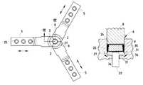
- FIG. 1is a partially fragmentary, front elevational view of a crimping die embodying the present invention, comprising an upper punch, and a lower segmented die utilizing an air chuck to release a crimped part;
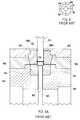
- FIG. 2is a cross-sectional view of the crimping die of FIG. 1, taken along the line II—II;
- FIG. 3is a cross-sectional view of the crimping die of FIG. 1, taken along the line III—III;
- FIG. 4is a top elevational view of the die segments
- FIG. 5is a partially fragmentary, front elevational view of the die segment of FIG. 4, taken along the line IV—IV;
- FIG. 6is a partially fragmentary, cross-sectional view illustrating the crimping of a part
- FIG. 7is a partially fragmentary, cross-sectional view illustrating the crimping of a part
- FIG. 8is a partially schematic top plan view of a prior art segmented crimping die
- FIG. 9Ais a partially fragmentary, cross-sectional view of the prior art crimping die of FIG. 8 taken along the line IXA—IXA;
- FIG. 9Bis a partially fragmentary, cross-sectional view of the prior art segment die of FIG. 9A showing the segmented die in the open position;
- FIG. 9Cis a partially fragmentary, cross-sectional view of the prior art crimping die of FIGS. 8 and 9 showing the upper punch in the raised position;
- FIG. 10is a schematic drawing of a membrane type air chuck.
- the terms “upper,” “lower,” “right,” “left,” “rear,” “front,” “vertical,” “horizontal,” and derivatives thereofshall relate to the invention as oriented in FIG. 1 .
- the inventionmay assume various alternative orientations and step sequences, except where expressly specified to the contrary.
- the specific devices and processes illustrated in the attached drawings and described in the following specificationare simply exemplary embodiments of the inventive concepts defined in the appended claims. Hence, specific dimensions and other physical characteristics relating to the embodiments disclosed herein are not to be considered as limiting, unless the claims expressly state otherwise.
- the reference numeral 1generally designates a forming die embodying the present invention, which is particularly designed for forming electrochemical cells and the like, as by crimping.
- the forming dieincludes at least two die segments 2 , at least a first one of which is movably mounted to a base or support structure 3 for shifting between closed and open positions.
- the die segments 2are mounted to the jaws 5 of a pneumatic, or “air” chuck 4 .
- the die segments 2together define a die cavity 6 (see also FIGS. 4-7) having an opening 7 when the die segments 2 are in the closed position.
- a punch 8is moveably mounted to the base 3 for shifting between a retracted position and an extended position.
- a powered actuatoris connected to at least one of the die segments 2 , and shifts the die segment 2 between the closed and opened positions, such that the electrochemical cell 9 positioned within the cavity 6 can be removed after crimping by shifting of the die segments 2 to the opened position.
- the base 3generally includes a vertical plate 10 , and upper and lower horizontal plates 11 and 12 , respectively.
- a bearing plate 13is slidably mounted to the vertical plate 10 by a pair of vertical rods 14 and pillow blocks 15 .
- a punch holder assembly 16is secured to the bearing plate 13 by conventional fasteners or the like (not shown). The punch holder assembly 16 securely holds the punch 8 in alignment with the lower cavity 6 formed by the die segments 2 .
- a rod 17is secured to the punch holder assembly 16 .
- Rod 17is attached to an electric servo, hydraulic driver, or other powered actuator (not shown) having sufficient force to form the part 9 in the die cavity 6 .
- the electrochemical cells 9are transferred to the die and crimped cells 9 are removed from the die after the forming operation. Any suitable mechanism, such as an index wheel, can be used for this purpose.
- the pneumatic chuck 4is securely supported on a horizontal plate 19 of the base 3 by a support assembly 18 .
- a lower punch 20is positioned below the pneumatic chuck 4 .
- Punch 20is slidably supported in alignment with the cavity 6 by a punch holder assembly 21 .
- a spring 22is supported by a stop block 23 , and biases the lower punch 20 upwardly into the die cavity 6 .
- An adjustable stop 24is threadably received within the stop block 23 , and limits the downward travel of the lower punch 20 .
- spring 22is relatively light weight, and lifts the formed electrochemical cell upwardly upon shifting of the die segments 2 to the opened, released position.
- each die segment 2is made of a suitable hardened tool steel, and includes a plurality of openings 25 to secure the die segment 2 to the jaws 5 of the pneumatic chuck 4 .
- Each die segment 2includes a sidewall 26 that is radiused, such that the die segments 2 together form a cylindrical die cavity 6 .
- the upper portion 28 of the sidewall 26is generally parallel to a vertical axis, and the lower portion 29 of the sidewall curves inwardly at radius 27 .
- a standard electrochemical cell 9includes a first metal casing portion 30 (also known as the “can”) having a shape similar to an inverted cup.
- the electrochemical cell 9also includes a second metal casing part 31 (also known as the “anode cup”) that is also generally cup shaped.
- the part 31has a slightly smaller diameter than part 30 , such that part 31 fits inside part 30 .
- a seal 34fits between parts 30 and 31 and prevents electrical conduction between parts 30 and 31 .
- the internal components 32 of the cell 9are sandwiched between the first and second parts 30 and 31 . During operation, an uncrimped electrochemical cell 9 is shifted into position at the upper portion of the die cavity 6 .
- the electrochemical cell 9is placed on the lower punch 20 , which is in its uppermost position due to the upward bias of spring 22 .
- the die segmentsare shifted into the extended, or closed, position by actuation of the pneumatic chuck 4 .
- the upper punch 8is then shifted downwardly by actuation of the electrochemical servo (not shown).
- the uncrimped electrochemical cell 9is pushed downwardly within the die cavity 6 until the electrochemical cell 9 is crimped on the radiused portion 27 of the die cavity 6 .
- the die segments 2are then shifted outwardly by actuation of the pneumatic chuck 4 into the unclamped, or open position.
- the powered ram and upper punch 8are then shifted upwardly, with the lower punch 20 holding the crimped cell 9 against the upper punch 8 .
- the die segments 2are then shifted into the extended, or closed, position; the finished, crimped cell 9 is removed; and a new, uncrimped cell 9 is brought into the die.
- the die segments 2could be in the open position when cell 9 is pushed into the die cavity and then closed to crimp the cell. However, this may leave undesirable marks, corresponding to the parting lines of die segments 2 , on the crimped surface of cell 9 .
- the die segments 2are mounted to a pneumatic chuck 4 .
- a preferred pneumatic chuckis a five-inch diaphragm chuck available from Northfield Precision Instrument Corporation of Island Park, N.Y.
- a membrane air chuck 40is shown schematically in FIG. 10 .
- Peripheral portions 41 of the jaws 5are mounted to a peripheral base 42 via a flexible diaphragm 43 .
- compressed airis introduced into air passageway 45 , a resulting force is applied to the lower side 44 of the jaws 5 by the chuck.
- Thiscauses jaws 5 and attached die segments 2 to pivot upward and outward to the open position.
- compressed airis introduced into air passageway 46 , the jaws 5 are moved to the closed position.
- pneumatic chucksmay also be used.
- a six-inch air chuckmodel no. 6-120NR-3, available from MicroCentric Corporation of Plainview, N.Y.
- jaws 5 of this type of chuckare mechanically driven radially inward and outward, to the closed and opened positions respectively.
- powered actuatorscould be connected to one or more of the die segments 2 to permit shifting of the die segments for release of the crimped cell.
- the die segments 2could be movably mounted to the base by a conventional slide arrangement, with an electrochemical, pneumatic, or other powered actuator connected to the movable die segment(s) for shifting between closed and open positions.
- Die segments 2may be mounted to jaws 5 by any suitable means, such as bolting, screwing, welding, clamping, pinning, gluing and so on; or die segments 2 may be an integral part of jaws 5 . It is also anticipated that other types of flexible members could be used instead of a flexible diaphragm. For example, each die segment could be biased by one or more separate flexible members. Because die segments 2 are fastened to jaws 5 , undesirable vertical movement of die segments 2 is prevented.
- the forming die of the present inventionfacilitates removal of the finished electrochemical cell, without damage of the cell, or contamination by lubricants or the like. Furthermore, the diameter of the cylindrical die cavity 6 can be made smaller relative to the part being formed, thereby permitting a tighter crimp of the electrochemical cell 9 , yet still permitting removal of the crimped cell without damage.
Landscapes
- Chemical & Material Sciences (AREA)
- Chemical Kinetics & Catalysis (AREA)
- Electrochemistry (AREA)
- General Chemical & Material Sciences (AREA)
- Engineering & Computer Science (AREA)
- Manufacturing & Machinery (AREA)
- Mechanical Engineering (AREA)
- Sealing Battery Cases Or Jackets (AREA)
- Mounting, Exchange, And Manufacturing Of Dies (AREA)
- Press-Shaping Or Shaping Using Conveyers (AREA)
- Yarns And Mechanical Finishing Of Yarns Or Ropes (AREA)
- Portable Nailing Machines And Staplers (AREA)
- Massaging Devices (AREA)
- Percussion Or Vibration Massage (AREA)
Abstract
Description
Claims (23)
Priority Applications (7)
| Application Number | Priority Date | Filing Date | Title |
|---|---|---|---|
| US09/495,528US6256853B1 (en) | 2000-01-31 | 2000-01-31 | Crimping die employing powered chuck |
| AT01906766TATE282504T1 (en) | 2000-01-31 | 2001-01-30 | CRIMPING DIE WITH A POWER OPERATED CHUCK |
| AU2001234636AAU2001234636A1 (en) | 2000-01-31 | 2001-01-30 | Crimping die employing powered chuck |
| PCT/US2001/002915WO2001054858A1 (en) | 2000-01-31 | 2001-01-30 | Crimping die employing powered chuck |
| DE60107205TDE60107205T2 (en) | 2000-01-31 | 2001-01-30 | CRIMP MATRIZE WITH A POWERED CHUCK |
| EP01906766AEP1255626B1 (en) | 2000-01-31 | 2001-01-30 | Crimping die employing powered chuck |
| US09/880,334US6427302B2 (en) | 2000-01-31 | 2001-06-13 | Crimping die employing powered chuck |
Applications Claiming Priority (1)
| Application Number | Priority Date | Filing Date | Title |
|---|---|---|---|
| US09/495,528US6256853B1 (en) | 2000-01-31 | 2000-01-31 | Crimping die employing powered chuck |
Related Child Applications (1)
| Application Number | Title | Priority Date | Filing Date |
|---|---|---|---|
| US09/880,334ContinuationUS6427302B2 (en) | 2000-01-31 | 2001-06-13 | Crimping die employing powered chuck |
Publications (1)
| Publication Number | Publication Date |
|---|---|
| US6256853B1true US6256853B1 (en) | 2001-07-10 |
Family
ID=23968976
Family Applications (2)
| Application Number | Title | Priority Date | Filing Date |
|---|---|---|---|
| US09/495,528Expired - LifetimeUS6256853B1 (en) | 2000-01-31 | 2000-01-31 | Crimping die employing powered chuck |
| US09/880,334Expired - LifetimeUS6427302B2 (en) | 2000-01-31 | 2001-06-13 | Crimping die employing powered chuck |
Family Applications After (1)
| Application Number | Title | Priority Date | Filing Date |
|---|---|---|---|
| US09/880,334Expired - LifetimeUS6427302B2 (en) | 2000-01-31 | 2001-06-13 | Crimping die employing powered chuck |
Country Status (6)
| Country | Link |
|---|---|
| US (2) | US6256853B1 (en) |
| EP (1) | EP1255626B1 (en) |
| AT (1) | ATE282504T1 (en) |
| AU (1) | AU2001234636A1 (en) |
| DE (1) | DE60107205T2 (en) |
| WO (1) | WO2001054858A1 (en) |
Cited By (5)
| Publication number | Priority date | Publication date | Assignee | Title |
|---|---|---|---|---|
| US7007537B1 (en)* | 2003-10-22 | 2006-03-07 | Omni-Lite Industries International, Inc. | Clam shell system |
| US20080096074A1 (en)* | 2006-10-23 | 2008-04-24 | Eveready Battery Company, Inc. | Electrochemical air cell batteries with air flow channels |
| US20100047666A1 (en)* | 2008-08-25 | 2010-02-25 | Eveready Battery Company, Inc. | Electrochemical Cell with Shaped Catalytic Electrode Casing |
| CN102338127A (en)* | 2011-10-10 | 2012-02-01 | 浙江双阳风机有限公司 | Impeller assembly machine for multi-blade centrifugal fan |
| US10461291B2 (en)* | 2017-12-12 | 2019-10-29 | Ford Global Technologies, Llc | Current-interrupt device for battery cell |
Families Citing this family (4)
| Publication number | Priority date | Publication date | Assignee | Title |
|---|---|---|---|---|
| US6730433B2 (en) | 2002-01-16 | 2004-05-04 | The Gillette Company | Thin-wall anode can |
| US6662436B1 (en)* | 2002-02-12 | 2003-12-16 | Beckett Air Incorporated | System for assembling a blower wheel |
| US9718157B2 (en)* | 2014-02-21 | 2017-08-01 | Ford Global Technologies, Llc | Expanding die for clinching and riveting operations |
| CN104550505B (en)* | 2015-01-13 | 2016-06-08 | 杭州沃镭智能科技股份有限公司 | The front and rear housings closing device of vacuum booster assembly line |
Citations (28)
| Publication number | Priority date | Publication date | Assignee | Title |
|---|---|---|---|---|
| US1844616A (en) | 1926-07-03 | 1932-02-09 | Lucius E Whiton | Jaw for lathe chucks, etc. |
| US1895401A (en) | 1930-08-04 | 1933-01-24 | Huston | Magnetic die |
| US2473673A (en)* | 1945-12-04 | 1949-06-21 | Clarence W Bell | Machine for straightening and sizing castings, forgings, stampings, or the like |
| FR1033186A (en)* | 1951-02-27 | 1953-07-08 | Forging machine | |
| US2663205A (en)* | 1949-05-06 | 1953-12-22 | Cameron Iron Works Inc | Forging process and apparatus |
| US2755839A (en)* | 1952-07-05 | 1956-07-24 | Ainsworth Mfg Corp | Apparatus for re-forming tubular members |
| US3604240A (en) | 1968-07-12 | 1971-09-14 | Oerlikon Buehrle Ag | Neck-forming apparatus for cartridge shells |
| US3837206A (en) | 1973-06-07 | 1974-09-24 | Power Conversion Inc | Method and apparatus for crimping battery casings |
| US3911719A (en) | 1974-12-02 | 1975-10-14 | Ragsdale Brothers Inc | High speed ejector mechanism |
| US4096728A (en) | 1977-07-27 | 1978-06-27 | Gulf & Western Manufacturing Company | Adjusting device for slide driven lift out actuators |
| US4197757A (en) | 1977-04-13 | 1980-04-15 | Hackett Kenneth P | Method and apparatus for the cold forming of metal |
| US4207812A (en) | 1978-03-01 | 1980-06-17 | General Electric Company | Apparatus for die stamping battery container can ends |
| US4418458A (en)* | 1978-08-09 | 1983-12-06 | Hunter John J | Apparatus for making pipe coupling joint |
| US4442184A (en) | 1983-03-31 | 1984-04-10 | Union Carbide Corporation | Dry path gas venting seal |
| US4457156A (en)* | 1981-01-29 | 1984-07-03 | Kabushiki Kaisha Kobe Seiko Sho | Horizontal tube upsetter |
| US4466266A (en)* | 1981-10-08 | 1984-08-21 | Gkn Forgings Limited | Forging apparatus |
| US4513600A (en) | 1983-01-03 | 1985-04-30 | The Minster Machine Company | Cam actuated ejector for a shell press |
| US4546988A (en) | 1983-08-05 | 1985-10-15 | The S-P Manufacturing Corporation | Chuck top jaw with removable insert |
| US4610155A (en) | 1982-10-14 | 1986-09-09 | Pfd Limited | Manufacture of article having undercut internal surface |
| US4655071A (en) | 1985-11-26 | 1987-04-07 | The U.S. Baird Corporation | Transfer press with quick change die set arrangement |
| US4693109A (en) | 1986-03-04 | 1987-09-15 | Wickes Manufacturing Company | Self-aligning tool assembly for die shaping workpieces |
| US4776197A (en) | 1986-09-23 | 1988-10-11 | Aquila Piombo Per Caccia E Tiro S.R.L. | Process and apparatus for producing an electrical battery pole or terminal |
| US4945749A (en) | 1989-10-30 | 1990-08-07 | General Motors Corporation | Cold forming dies and cold forming process |
| US5279905A (en) | 1992-03-09 | 1994-01-18 | Eveready Battery Company, Inc. | Miniature zinc-air cell having an indium plated anode cupe |
| US5296317A (en) | 1992-09-03 | 1994-03-22 | Water Gremlin Co. | High torque battery terminal and method of making same |
| US5425170A (en) | 1993-06-17 | 1995-06-20 | Tulip Corporation | Side wall electrical battery terminal |
| US5528815A (en) | 1990-04-03 | 1996-06-25 | Webb; Edward L. T. | Clinching tool for sheet metal joining |
| US5662717A (en)* | 1995-05-05 | 1997-09-02 | Rayovac Corporation | Metal-air cathode can having reduced corner radius and electrochemical cells made therewith |
Family Cites Families (10)
| Publication number | Priority date | Publication date | Assignee | Title |
|---|---|---|---|---|
| US2940497A (en)* | 1956-01-18 | 1960-06-14 | Greenlee Bros & Co | Portable hydraulic press |
| US3706123A (en)* | 1970-12-31 | 1972-12-19 | Moore & Co Samuel | Hydraulically actuated apparatus |
| US4034593A (en)* | 1976-04-09 | 1977-07-12 | The Weatherhead Company | Crimping machine with automatic swing open pushers |
| US4139207A (en)* | 1978-01-30 | 1979-02-13 | Grimes Larry E | Double grip air chuck |
| JPS5556362A (en)* | 1978-10-20 | 1980-04-25 | Matsushita Electric Ind Co Ltd | Sealing method for button-type battery |
| JPH03163750A (en)* | 1989-11-20 | 1991-07-15 | Toshiba Battery Co Ltd | Manufacture of flat battery |
| JPH03182046A (en)* | 1989-12-08 | 1991-08-08 | Seiko Electronic Components Ltd | Manufacture of battery |
| JPH0556362A (en) | 1991-08-21 | 1993-03-05 | Matsushita Electric Ind Co Ltd | Video recording reservation device |
| JP3163750B2 (en) | 1992-05-19 | 2001-05-08 | 株式会社モリタ東京製作所 | Automatic cup filling device |
| JP3182046B2 (en) | 1994-07-27 | 2001-07-03 | 中外炉工業株式会社 | Method and apparatus for operating regenerative heat storage combustion system |
- 2000
- 2000-01-31USUS09/495,528patent/US6256853B1/ennot_activeExpired - Lifetime
- 2001
- 2001-01-30EPEP01906766Apatent/EP1255626B1/ennot_activeExpired - Lifetime
- 2001-01-30WOPCT/US2001/002915patent/WO2001054858A1/enactiveIP Right Grant
- 2001-01-30AUAU2001234636Apatent/AU2001234636A1/ennot_activeAbandoned
- 2001-01-30ATAT01906766Tpatent/ATE282504T1/ennot_activeIP Right Cessation
- 2001-01-30DEDE60107205Tpatent/DE60107205T2/ennot_activeExpired - Lifetime
- 2001-06-13USUS09/880,334patent/US6427302B2/ennot_activeExpired - Lifetime
Patent Citations (28)
| Publication number | Priority date | Publication date | Assignee | Title |
|---|---|---|---|---|
| US1844616A (en) | 1926-07-03 | 1932-02-09 | Lucius E Whiton | Jaw for lathe chucks, etc. |
| US1895401A (en) | 1930-08-04 | 1933-01-24 | Huston | Magnetic die |
| US2473673A (en)* | 1945-12-04 | 1949-06-21 | Clarence W Bell | Machine for straightening and sizing castings, forgings, stampings, or the like |
| US2663205A (en)* | 1949-05-06 | 1953-12-22 | Cameron Iron Works Inc | Forging process and apparatus |
| FR1033186A (en)* | 1951-02-27 | 1953-07-08 | Forging machine | |
| US2755839A (en)* | 1952-07-05 | 1956-07-24 | Ainsworth Mfg Corp | Apparatus for re-forming tubular members |
| US3604240A (en) | 1968-07-12 | 1971-09-14 | Oerlikon Buehrle Ag | Neck-forming apparatus for cartridge shells |
| US3837206A (en) | 1973-06-07 | 1974-09-24 | Power Conversion Inc | Method and apparatus for crimping battery casings |
| US3911719A (en) | 1974-12-02 | 1975-10-14 | Ragsdale Brothers Inc | High speed ejector mechanism |
| US4197757A (en) | 1977-04-13 | 1980-04-15 | Hackett Kenneth P | Method and apparatus for the cold forming of metal |
| US4096728A (en) | 1977-07-27 | 1978-06-27 | Gulf & Western Manufacturing Company | Adjusting device for slide driven lift out actuators |
| US4207812A (en) | 1978-03-01 | 1980-06-17 | General Electric Company | Apparatus for die stamping battery container can ends |
| US4418458A (en)* | 1978-08-09 | 1983-12-06 | Hunter John J | Apparatus for making pipe coupling joint |
| US4457156A (en)* | 1981-01-29 | 1984-07-03 | Kabushiki Kaisha Kobe Seiko Sho | Horizontal tube upsetter |
| US4466266A (en)* | 1981-10-08 | 1984-08-21 | Gkn Forgings Limited | Forging apparatus |
| US4610155A (en) | 1982-10-14 | 1986-09-09 | Pfd Limited | Manufacture of article having undercut internal surface |
| US4513600A (en) | 1983-01-03 | 1985-04-30 | The Minster Machine Company | Cam actuated ejector for a shell press |
| US4442184A (en) | 1983-03-31 | 1984-04-10 | Union Carbide Corporation | Dry path gas venting seal |
| US4546988A (en) | 1983-08-05 | 1985-10-15 | The S-P Manufacturing Corporation | Chuck top jaw with removable insert |
| US4655071A (en) | 1985-11-26 | 1987-04-07 | The U.S. Baird Corporation | Transfer press with quick change die set arrangement |
| US4693109A (en) | 1986-03-04 | 1987-09-15 | Wickes Manufacturing Company | Self-aligning tool assembly for die shaping workpieces |
| US4776197A (en) | 1986-09-23 | 1988-10-11 | Aquila Piombo Per Caccia E Tiro S.R.L. | Process and apparatus for producing an electrical battery pole or terminal |
| US4945749A (en) | 1989-10-30 | 1990-08-07 | General Motors Corporation | Cold forming dies and cold forming process |
| US5528815A (en) | 1990-04-03 | 1996-06-25 | Webb; Edward L. T. | Clinching tool for sheet metal joining |
| US5279905A (en) | 1992-03-09 | 1994-01-18 | Eveready Battery Company, Inc. | Miniature zinc-air cell having an indium plated anode cupe |
| US5296317A (en) | 1992-09-03 | 1994-03-22 | Water Gremlin Co. | High torque battery terminal and method of making same |
| US5425170A (en) | 1993-06-17 | 1995-06-20 | Tulip Corporation | Side wall electrical battery terminal |
| US5662717A (en)* | 1995-05-05 | 1997-09-02 | Rayovac Corporation | Metal-air cathode can having reduced corner radius and electrochemical cells made therewith |
Cited By (5)
| Publication number | Priority date | Publication date | Assignee | Title |
|---|---|---|---|---|
| US7007537B1 (en)* | 2003-10-22 | 2006-03-07 | Omni-Lite Industries International, Inc. | Clam shell system |
| US20080096074A1 (en)* | 2006-10-23 | 2008-04-24 | Eveready Battery Company, Inc. | Electrochemical air cell batteries with air flow channels |
| US20100047666A1 (en)* | 2008-08-25 | 2010-02-25 | Eveready Battery Company, Inc. | Electrochemical Cell with Shaped Catalytic Electrode Casing |
| CN102338127A (en)* | 2011-10-10 | 2012-02-01 | 浙江双阳风机有限公司 | Impeller assembly machine for multi-blade centrifugal fan |
| US10461291B2 (en)* | 2017-12-12 | 2019-10-29 | Ford Global Technologies, Llc | Current-interrupt device for battery cell |
Also Published As
| Publication number | Publication date |
|---|---|
| ATE282504T1 (en) | 2004-12-15 |
| AU2001234636A1 (en) | 2001-08-07 |
| WO2001054858A1 (en) | 2001-08-02 |
| US6427302B2 (en) | 2002-08-06 |
| EP1255626A1 (en) | 2002-11-13 |
| EP1255626B1 (en) | 2004-11-17 |
| DE60107205T2 (en) | 2005-11-03 |
| US20010029769A1 (en) | 2001-10-18 |
| WO2001054858A9 (en) | 2002-10-24 |
| DE60107205D1 (en) | 2004-12-23 |
Similar Documents
| Publication | Publication Date | Title |
|---|---|---|
| JP4522378B2 (en) | Press molding method and apparatus | |
| US4989443A (en) | Crimping apparatus | |
| US6256853B1 (en) | Crimping die employing powered chuck | |
| US20090116932A1 (en) | Process for Producing Molded Article with Undercut, Forging Apparatus Therefor, and Intermediate Molded Object | |
| WO2010035511A1 (en) | Device and method for assembling retainer and cotter | |
| JP2008142772A (en) | Total shearing die | |
| JP4814118B2 (en) | Gear forming method and apparatus | |
| JPH02155524A (en) | Set of tool for combining sheet-shaped metal piece | |
| JP3694597B2 (en) | Cold forging die | |
| JPH09141380A (en) | Method and apparatus for forging bevel gears | |
| JP3704261B2 (en) | Double acting die holder mechanism | |
| EP0623408B1 (en) | Method and apparatus for manufacturing a metal element | |
| JPS63165025A (en) | Punching die | |
| JP4941419B2 (en) | Forging equipment | |
| CN113020406B (en) | Blanking die | |
| CN115722589B (en) | Side slider assembly and side forming device | |
| JPH0614897Y2 (en) | Mold work positioning device | |
| CN218136569U (en) | Drilling machine for mold production | |
| SU1586843A1 (en) | Die for group stamping of forgings | |
| RU2064852C1 (en) | Matrix for turret-type automatic die | |
| JPH08257668A (en) | Forging method and apparatus | |
| SU1349859A1 (en) | Die for rolling a loop | |
| JPH01166836A (en) | Mold work holding structure | |
| SU1319994A1 (en) | Upsetting die | |
| JP4804293B2 (en) | Manufacturing method of molded product having undercut portion |
Legal Events
| Date | Code | Title | Description |
|---|---|---|---|
| AS | Assignment | Owner name:EVEREADY BATTERY COMPANY, INC., OHIO Free format text:ASSIGNMENT OF ASSIGNORS INTEREST;ASSIGNORS:PIANTONI, RAYMOND W.;RAY, ROBERT E., JR.;REEL/FRAME:010578/0974;SIGNING DATES FROM 20000118 TO 20000125 | |
| STCF | Information on status: patent grant | Free format text:PATENTED CASE | |
| FPAY | Fee payment | Year of fee payment:4 | |
| FPAY | Fee payment | Year of fee payment:8 | |
| FPAY | Fee payment | Year of fee payment:12 | |
| AS | Assignment | Owner name:ENERGIZER BRANDS, LLC, MISSOURI Free format text:ASSIGNMENT OF ASSIGNORS INTEREST;ASSIGNOR:EVEREADY BATTERY COMPANY, INC.;REEL/FRAME:036019/0814 Effective date:20150601 | |
| AS | Assignment | Owner name:JPMORGAN CHASE BANK, N.A., AS AGENT, ILLINOIS Free format text:SECURITY AGREEMENT;ASSIGNOR:ENERGIZER BRANDS, LLC;REEL/FRAME:036106/0392 Effective date:20150630 | |
| AS | Assignment | Owner name:ENERGIZER BRANDS, LLC, MISSOURI Free format text:CORRECTIVE ASSIGNMENT TO CORRECT THE APPLICATION NUMBER 29/499,135 PREVIOUSLY RECORDED AT REEL: 036019 FRAME: 814. ASSIGNOR(S) HEREBY CONFIRMS THE ASSIGNMENT;ASSIGNOR:EVEREADY BATTERY COMPANY;REEL/FRAME:040054/0660 Effective date:20160601 | |
| AS | Assignment | Owner name:ENERGIZER BRANDS, LLC, MISSOURI Free format text:TERMINATION AND RELEASE OF SECURITY INTEREST IN PATENT RIGHTS;ASSIGNOR:JPMORGAN CHASE BANK, N.A., AS ADMINISTRATIVE AGENT;REEL/FRAME:048888/0300 Effective date:20190102 Owner name:JPMORGAN CHASE BANK, N.A., AS ADMINISTRATIVE AGENT, ILLINOIS Free format text:PATENT SECURITY AGREEMENT;ASSIGNORS:ENERGIZER HOLDINGS, INC.;AMERICAN COVERS, LLC;ASSOCIATED PRODUCTS, LLC;AND OTHERS;REEL/FRAME:048029/0246 Effective date:20190102 Owner name:JPMORGAN CHASE BANK, N.A., AS ADMINISTRATIVE AGENT Free format text:PATENT SECURITY AGREEMENT;ASSIGNORS:ENERGIZER HOLDINGS, INC.;AMERICAN COVERS, LLC;ASSOCIATED PRODUCTS, LLC;AND OTHERS;REEL/FRAME:048029/0246 Effective date:20190102 |