US6256643B1 - Systems and methods for storing, retrieving, and manipulating data in medical processing devices - Google Patents
Systems and methods for storing, retrieving, and manipulating data in medical processing devicesDownload PDFInfo
- Publication number
- US6256643B1 US6256643B1US09/037,356US3735698AUS6256643B1US 6256643 B1US6256643 B1US 6256643B1US 3735698 AUS3735698 AUS 3735698AUS 6256643 B1US6256643 B1US 6256643B1
- Authority
- US
- United States
- Prior art keywords
- data
- file
- task
- block
- storage medium
- Prior art date
- Legal status (The legal status is an assumption and is not a legal conclusion. Google has not performed a legal analysis and makes no representation as to the accuracy of the status listed.)
- Expired - Lifetime
Links
Images


Classifications
- A—HUMAN NECESSITIES
- A61—MEDICAL OR VETERINARY SCIENCE; HYGIENE
- A61M—DEVICES FOR INTRODUCING MEDIA INTO, OR ONTO, THE BODY; DEVICES FOR TRANSDUCING BODY MEDIA OR FOR TAKING MEDIA FROM THE BODY; DEVICES FOR PRODUCING OR ENDING SLEEP OR STUPOR
- A61M1/00—Suction or pumping devices for medical purposes; Devices for carrying-off, for treatment of, or for carrying-over, body-liquids; Drainage systems
- A61M1/36—Other treatment of blood in a by-pass of the natural circulatory system, e.g. temperature adaptation, irradiation ; Extra-corporeal blood circuits
- A61M1/3693—Other treatment of blood in a by-pass of the natural circulatory system, e.g. temperature adaptation, irradiation ; Extra-corporeal blood circuits using separation based on different densities of components, e.g. centrifuging
- A61M1/3696—Other treatment of blood in a by-pass of the natural circulatory system, e.g. temperature adaptation, irradiation ; Extra-corporeal blood circuits using separation based on different densities of components, e.g. centrifuging with means for adding or withdrawing liquid substances during the centrifugation, e.g. continuous centrifugation
- A—HUMAN NECESSITIES
- A61—MEDICAL OR VETERINARY SCIENCE; HYGIENE
- A61M—DEVICES FOR INTRODUCING MEDIA INTO, OR ONTO, THE BODY; DEVICES FOR TRANSDUCING BODY MEDIA OR FOR TAKING MEDIA FROM THE BODY; DEVICES FOR PRODUCING OR ENDING SLEEP OR STUPOR
- A61M2205/00—General characteristics of the apparatus
- A61M2205/50—General characteristics of the apparatus with microprocessors or computers
- A61M2205/502—User interfaces, e.g. screens or keyboards
- G—PHYSICS
- G05—CONTROLLING; REGULATING
- G05B—CONTROL OR REGULATING SYSTEMS IN GENERAL; FUNCTIONAL ELEMENTS OF SUCH SYSTEMS; MONITORING OR TESTING ARRANGEMENTS FOR SUCH SYSTEMS OR ELEMENTS
- G05B2219/00—Program-control systems
- G05B2219/20—Pc systems
- G05B2219/24—Pc safety
- G05B2219/24137—Non volatile memory to store program on power loss
- G—PHYSICS
- G05—CONTROLLING; REGULATING
- G05B—CONTROL OR REGULATING SYSTEMS IN GENERAL; FUNCTIONAL ELEMENTS OF SUCH SYSTEMS; MONITORING OR TESTING ARRANGEMENTS FOR SUCH SYSTEMS OR ELEMENTS
- G05B2219/00—Program-control systems
- G05B2219/20—Pc systems
- G05B2219/25—Pc structure of the system
- G05B2219/25265—Flash memory
- G—PHYSICS
- G05—CONTROLLING; REGULATING
- G05B—CONTROL OR REGULATING SYSTEMS IN GENERAL; FUNCTIONAL ELEMENTS OF SUCH SYSTEMS; MONITORING OR TESTING ARRANGEMENTS FOR SUCH SYSTEMS OR ELEMENTS
- G05B2219/00—Program-control systems
- G05B2219/20—Pc systems
- G05B2219/26—Pc applications
- G05B2219/2657—Blood, urine analyzer
- G—PHYSICS
- G06—COMPUTING OR CALCULATING; COUNTING
- G06F—ELECTRIC DIGITAL DATA PROCESSING
- G06F3/00—Input arrangements for transferring data to be processed into a form capable of being handled by the computer; Output arrangements for transferring data from processing unit to output unit, e.g. interface arrangements
- G06F3/06—Digital input from, or digital output to, record carriers, e.g. RAID, emulated record carriers or networked record carriers
- G06F3/0601—Interfaces specially adapted for storage systems
- G06F3/0628—Interfaces specially adapted for storage systems making use of a particular technique
- G06F3/0662—Virtualisation aspects
- G06F3/0664—Virtualisation aspects at device level, e.g. emulation of a storage device or system
- G—PHYSICS
- G06—COMPUTING OR CALCULATING; COUNTING
- G06F—ELECTRIC DIGITAL DATA PROCESSING
- G06F3/00—Input arrangements for transferring data to be processed into a form capable of being handled by the computer; Output arrangements for transferring data from processing unit to output unit, e.g. interface arrangements
- G06F3/06—Digital input from, or digital output to, record carriers, e.g. RAID, emulated record carriers or networked record carriers
- G06F3/08—Digital input from, or digital output to, record carriers, e.g. RAID, emulated record carriers or networked record carriers from or to individual record carriers, e.g. punched card, memory card, integrated circuit [IC] card or smart card
- G—PHYSICS
- G16—INFORMATION AND COMMUNICATION TECHNOLOGY [ICT] SPECIALLY ADAPTED FOR SPECIFIC APPLICATION FIELDS
- G16H—HEALTHCARE INFORMATICS, i.e. INFORMATION AND COMMUNICATION TECHNOLOGY [ICT] SPECIALLY ADAPTED FOR THE HANDLING OR PROCESSING OF MEDICAL OR HEALTHCARE DATA
- G16H40/00—ICT specially adapted for the management or administration of healthcare resources or facilities; ICT specially adapted for the management or operation of medical equipment or devices
- G16H40/60—ICT specially adapted for the management or administration of healthcare resources or facilities; ICT specially adapted for the management or operation of medical equipment or devices for the operation of medical equipment or devices
- G16H40/63—ICT specially adapted for the management or administration of healthcare resources or facilities; ICT specially adapted for the management or operation of medical equipment or devices for the operation of medical equipment or devices for local operation
- Y—GENERAL TAGGING OF NEW TECHNOLOGICAL DEVELOPMENTS; GENERAL TAGGING OF CROSS-SECTIONAL TECHNOLOGIES SPANNING OVER SEVERAL SECTIONS OF THE IPC; TECHNICAL SUBJECTS COVERED BY FORMER USPC CROSS-REFERENCE ART COLLECTIONS [XRACs] AND DIGESTS
- Y10—TECHNICAL SUBJECTS COVERED BY FORMER USPC
- Y10S—TECHNICAL SUBJECTS COVERED BY FORMER USPC CROSS-REFERENCE ART COLLECTIONS [XRACs] AND DIGESTS
- Y10S707/00—Data processing: database and file management or data structures
- Y10S707/99951—File or database maintenance
- Y10S707/99956—File allocation
Definitions
- the inventionrelates to systems and methods for recording data during the course of fluid processing procedures, such as those carried out by blood processing systems and the like.
- microprocessorswith resident program software.
- the microprocessorsalso usually include some type of interface through which the operator views and comprehends information regarding the operation of the fluid processing systems.
- the inventionprovides systems and methods, which fully integrate data recording functions with processing functions.
- the same instrument that carries out the processing tasksalso performs the data recording functions, without the need for add-on, external data recording systems.
- the inventionalso provides systems and methods, which fully automate necessary data recording functions, so that they can be accomplished “in the background,” without significant operator intervention or control.
- the inventionalso provides robust systems and methods, which carry out data recording functions that withstand real world abuse, such as power failure or corruption of stored data.
- This “crash-proof” aspectis particularly significant in an embedded software systems environment, where an instrument may be powered off at any time.
- One aspect of the inventionprovides systems and methods for processing data during a blood processing procedure.
- the systems and methodsmonitor status conditions over time during the blood processing procedure and generate data based upon monitored status conditions.
- the systems and methodswrite the data to a flash memory storage medium.
- the systems and methodsretrieve and manipulate the data written to the flash memory storage medium.
- flash memoryprovides reliability and compact size, so that robust data storage, retrieval, and processing functions can be carried out on-board a blood processing device, without need for external computing devices and without concern about the durability and reliability of the data storage functions.
- blood processing systems and methodsemploy a device that has processing hardware to carry out a blood processing procedure.
- a processing control managerresides on the device to monitor status conditions over time during the blood processing procedure.
- a data interfacealso resides on the device. The data interface includes a data storage medium formatted to allocate discrete block file spaces to receive data.
- chronologic data or time-specific datacan be created, based upon sensed conditions by a file generator task, which resides on the device.
- a file manager taskoperates to append chronologic data in an allocated file space to create a chronologic block file.
- the chronologic block fileprovides a time-ordered account of processing activities or hardware conditions.
- the file management elementalso operates to block-write time-specific data to another allocated file space.
- each time-specific data fileprovides a snap-shot of processing conditions at a given point in time.
- the data file structure createdwithstands corruption of data due to power failure.
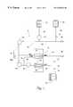
- FIG. 1is a diagrammatic view of a dual needle platelet collection system that includes a controller that embodies the features of the invention
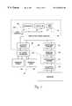
- FIG. 2is a diagrammatic flow chart view of the controller and the associated instrument manager and graphical user interface
- FIG. 3is another diagrammatic view of the controller and the associated instrument manager and graphical user interface shown in FIG. 2, and further showing the command and status flow hierarchy;
- FIG. 4is a view of the dual region graphical user interface screen, showing the block and touch activated fields that the interface screen contains, and also showing the Main Menu in the working region of the interface screen;
- FIG. 5a view of the dual region interface screen, showing the Select Procedures Submenu in the working region of the interface screen;
- FIG. 6Aa view of the dual region interface screen, showing the Special Features Submenu in the working region of the interface screen;
- FIG. 6Ba view of the dual region interface screen, showing the File Manger Submenu in the working region of the interface screen;
- FIG. 7is a diagrammatic flow chart view of the controller and the associated data interface
- FIG. 8is a diagrammatic view of the block file structure of the storage device of the data interface shown in FIG. 7;
- FIG. 9is a diagrammatic view of the directory table of the block file structure shown in FIG. 8;
- FIG. 10is a diagrammatic view of one block file space allocated in the block file structure shown in FIG. 8;
- FIG. 11is a diagrammatic view of the ringfile function, which controls the writing of data into the block file space shown in FIG. 10;
- FIG. 12a view of the dual region interface screen, showing the File System Information Submenu in the working region of the interface screen;
- FIG. 13a view of the dual region interface screen, showing the File Directory Submenu in the working region of the interface screen;
- FIG. 14is a representative Procedure Report that the data interface shown in FIG. 7 can generate;
- FIG. 15is a representative Event Report that the data interface shown in FIG. 7 can generate;
- FIG. 16a view of the dual region interface screen, showing the Print Procedure Reports Submenu in the working region of the interface screen;
- FIG. 17a view of the dual region interface screen, showing the Log Viewer Submenu in the working region of the interface screen;
- FIG. 18a view of the dual region interface screen, showing the System Configuration Submenu in the working region of the interface screen;
- FIG. 19a view of the dual region interface screen, showing the Set Configuration Submenu in the working region of the interface screen;
- FIG. 20is a schematic view of the predictor function of the data interface.
- FIG. 21is a schematic view of the import configuration function of the data interface.
- FIG. 1shows in diagrammatic form a fluid processing system 10 .
- the system 10can be used for processing various fluids.
- the system 10is particularly well suited for processing fluids for medical purposes, like whole blood and other suspensions of biological cellular materials. Accordingly, the illustrated embodiment shows the system 10 used for this purpose.
- the system 10includes an arrangement of durable hardware elements.
- the hardware elementswill vary according to the nature and type of processing system.
- the hardware elementswill include a centrifuge 12 , in which whole blood (WB) is separated into its various therapeutic components, like platelets, plasma, and red blood cells (RBC).
- WBwhole blood
- RBCred blood cells
- the hardware elementswill also include various pumps, which are typically peristaltic (designated P1 to P4); and various in line clamps and valves (designated V1 to V3).
- P1 to P4peristaltic
- V1 to V3various in line clamps and valves
- FIG. 1does not show, like solenoids, pressure monitors, and the like.
- the system 10typically also includes some form of a disposable fluid processing assembly 14 used in association with the hardware elements.
- the assembly 14includes a two stage processing chamber 16 .
- the centrifuge 12rotates the processing chamber 16 to centrifugally separate blood components.
- the construction of the two stage processing chamber 16can vary. For example, it can take the form of double bags, like the processing chambers shown in Cullis et al. U.S. Pat. No. 4,146,172. Alternatively, the processing chamber 16 can take the form of an elongated two stage integral bag, like that shown in Brown U.S. Pat. No. 5,370,802.
- the processing assembly 14also includes an array of flexible tubing that forms a fluid circuit.
- the fluid circuitconveys liquids to and from the processing chamber 16 .
- the pumps P1-P4 and the valves V1-V3engage the tubing to govern the fluid flow in prescribed ways.
- the fluid circuitfurther includes a number of containers (designated C1 to C3) to dispense and receive liquids during processing.
- a controller 18governs the operation of the various hardware elements to carry out one or more processing tasks using the assembly 14 .
- the inventionspecifically concerns important attributes of the controller 18 .
- FIG. 1shows the system 10 configured to carry out an automated two needle platelet collection procedure.
- a first tubing branch 20 and the whole blood inlet pump P2direct WB from a draw needle 22 into the first stage 24 of the processing chamber 16 .
- an auxiliary tubing branch 26meters anticoagulant from the container C1to the WB flow through the anticoagulant pump P1.
- the container C2holds saline solution.
- Another auxiliary tubing branch 28conveys the saline into the first tubing branch 20 , via the in line valve V1, for use in priming and purging air from the system 10 before processing begins. Saline solution is also introduced again after processing ends to flush residual components from the assembly 14 for return to the donor.
- Anticoagulated WBenters and fills the first stage 24 of the processing chamber 24 . There, centrifugal forces generated during rotation of the centrifuge 12 separate WB into red blood cells (RBC) and platelet-rich plasma (PRP).
- RBCred blood cells
- PRPplatelet-rich plasma
- the PRP pump P 4operates to draw PRP from the first stage 24 of the processing chamber 16 into a second tubing branch 30 for transport to the second stage 32 of the processing chamber 16 . There, the PRP is separated into platelet concentrate (PC) and platelet-poor plasma (PPP).
- PCplatelet concentrate
- PPPplatelet-poor plasma
- the system 10includes a recirculation tubing branch 34 and an associated recirculation pump P3.
- the processing controller 18operates the pump P3 to divert a portion of the PRP exiting the first stage 24 of the processing chamber 16 for remixing with the WB entering the first stage 24 of the processing chamber 16 .
- the illustrated two needle systemsimultaneously returns RBC from the first chamber stage 24 , along with a portion of the PPP from the second chamber stage 32 , to the donor through a return needle 36 through tubing branches 38 and 40 and in line valve V2.
- the system 10also collects PC in some of the containers C3 through tubing branches 38 and 42 and in line valve V3 for storage and therapeutic use.
- the system 10can also collect PPP in some of the containers C3 through the same fluid path.
- the controller 18carries out the overall process control and monitoring functions for the system 10 as just described.
- the controllercomprises a main processing unit (MPU) 44 .
- the MPU 44comprises a type 68030 microprocessor made by Motorola Corporation, although other types of conventional microprocessors can be used.
- the MPU 44employs conventional real time multi-tasking to allocate MPU cycles to processing tasks.
- a periodic timer interrupt(for example, every 5 milliseconds) preempts the executing task and schedules another that is in a ready state for execution. If a reschedule is requested, the highest priority task in the ready state is scheduled. Otherwise, the next task on the list in the ready state is schedule.
- the MPU 44includes an application control manager 46 .
- the application control manager 46administers the activation of a library 48 of control applications (designated A1 to A3).
- Each control application A1-A3prescribes procedures for carrying out given functional tasks using the system hardware (e.g., the centrifuge 12 , the pumps P1-P4, and the valves V1-V3) in a predetermined way.
- the applications A1-A3reside as process software in EPROM's in the MPU 44 .
- the number of applications A1-A3can vary.
- the library 48includes at least one clinical procedure application A1.
- the procedure application A1contains the steps to carry out one prescribed clinical processing procedure.
- the library 48includes a procedure application A1 for carrying out the dual needle platelet collection process, as already generally described in connection with FIG. 1 .
- additional procedure applicationscan be, and typically will be, included.
- the library 48can include a procedure application for carrying out a conventional single needle platelet collection process (A1′).
- the library 48also includes at least one additional, non-procedure application.
- the non-clinical procedural applicationcontains the procedures to carry out a system configuration or support utility.
- the library 48includes a configuration application A2, which contains the procedures for allowing the operator to configure the default operating parameters of the system 10 .
- the library 48also includes a main menu application A3, which coordinates the selection of the various applications A1-A3 by the operator, as will also be described in greater detail later.
- the library 48can include a diagnosis application, which contains the procedures aiding service personnel in diagnosing and troubleshooting the functional integrity of the system, and a system restart application, which performs a full restart of the system, should the system become unable to manage or recover from an error condition.
- a diagnosis applicationwhich contains the procedures aiding service personnel in diagnosing and troubleshooting the functional integrity of the system
- a system restart applicationwhich performs a full restart of the system, should the system become unable to manage or recover from an error condition.
- An instrument manager 50also resides as process software in EPROM's in the MPU 44 .
- the instrument manager 50communicates with the application control manager 46 .
- the instrument manager 50also communicates with low level peripheral controllers 52 for the pumps, solenoids, valves, and other functional hardware of the system.
- the application control manager 46sends specified Perform_Function# commands in abstract form to the instrument manager 50 , as called up by the activated application A1-A3.
- the instrument manager 50identifies the peripheral controller or controllers 52 for performing the function and compiles hardware-specific Operate_Hardware# commands into the command tables for the particular peripheral controllers 52 .
- the peripheral controllers 52communicate directly with the hardware to implement the hardware-specific commands generated by the instrument manager 50 , causing the hardware to operate in a specified way to carry out the abstract Perform_Function# commands.
- a communication manager 54manages low-level protocol and communications between the instrument manager 50 and the peripheral controllers 52 .
- the instrument manager 50also conveys back to the application control manager 46 status data about the operational and functional conditions of the processing procedure.
- the status datais expressed in terms of, for example, fluid flow rates, sensed pressures, and fluid volumes measured.
- the application control manager 46processes and uses the status data in various ways. In one way, the application control manager 46 transmits selected status data for display to the operator, as will be described later. In another way, the application control manager 46 monitors operational and functional conditions using the status data to detect abnormal system conditions requiring operator intervention or system shutdown.
- the MPU 44also includes a condition manager 56 that resides in the data flow path between the instrument manager 50 and the communications manager 54 .
- the condition manager 56also monitors status data and other operational states of the hardware to detect abnormal conditions that are either not detected or are left uncorrected by the application control manager 46 . Upon detecting such abnormal conditions, the condition manager 56 provides fail-safe support by suspending system operation.
- the described control hierarchycreates an abstract, “virtual” interface between the applications resident in the application control manager 46 and the hardware elements of the system 10 .
- the high level process software resident in the application control manager 46communicates with lower level implementing process software in the instrument manager 50 , instead of communicating directly with hardware elements.
- the intermediate instrument manager 50isolates or “hides” all hardware-specific commands from the application control manager 46 .
- the applicationspass abstract Perform_Function# commands to the instrument manager 50 , and the instrument manager 50 converts these abstract commands into the specific Operate_Hardware# commands unique to the particular hardware elements, all without further participation by the procedure applications A1-A3 themselves.
- the data flow between the instrument manager 50 and the hardware elements of the system 10is invisible to the activated application A1-A3.
- the instrument manager 50forms a part of the same MPU in which the application control manager 46 resides.
- the instrument manager 50can reside on a separate processing unit.
- the MPU 44also includes an interactive user interface 58 .
- the interface 58allows the operator to view and comprehend information regarding the operation of the system 10 .
- the interface 58also allows the operator to select applications residing in the application control manager 46 , as well as to change certain functions and performance criteria of the system 10 .
- the interface 58includes an interface screen 60 and, preferably, an audio device 62 .
- the interface screen 60displays information for viewing by the operator in alpha-numeric format and as graphical images.
- the audio device 62provides audible prompts either to gain the operator's attention or to acknowledge operator actions.
- the interface screen 60also serves as an input device. It receives input from the operator by conventional touch activation, as will be described later. Alternatively or in combination with touch activation, a mouse or keyboard could be used as input devices.
- An interface controller 64communicates with the interface screen 60 and audio device 62 .
- the interface controller 64in turn, communicates with an interface manager 66 , which in turn communicates with the application control manager 46 .
- the interface controller 64 and the interface manager 66reside as process software in EPROM's in the MPU 44 .
- the application control manager 46sends to the interface manager 66 specified field values reflecting selected status data received from the instrument manager 50 .
- the application control manager 46also sends to the interface manager 66 prescribed abstract Create_Display# and Create_Audio# commands called for by the activated application.
- the interface manager 66processes these field values and the abstract Create_Display# commands to generate specific Format_Display# commands.
- the Format_Display# commandscontrol the particular format, attributes, and protocols necessary to create, refresh, and close the visual display on the interface screen 60 .
- the interface manager 66processes the abstract Create_Audio# commands to generate specific Format_Audio# commands.
- the Format_Audio# commandsdictate the format and attributes of the audio output called for by the activated application.
- the interface manager 66conveys the processed Format_Display# and _Audio# commands to the interface controller 64 .
- the interface controller 64provides low level control functions that draw boxes and lines, forms text or graphical characters, and provides the formatting ant attributes of the display on the interface screen 60 .
- the interface controller 64also provides low level control functions that drive the audio device 62 based upon Format_Audio# commands received from the interface manager 66 .
- the interface controller 64also accepts Field#_Select commands generated by touch activation of the interface screen 60 , as will be described in greater detail later.
- the interface controller 64passes this touch activated input to the interface manager 66 in the form of Touch#_Codes.
- the interface manager 66processes the Touch#_Codes to the application control manager 46 , either as function codes or as changed field values.
- the application control manager 46implements the function codes or changed field values and passes them to the instrument manager 50 .
- This control hierarchyalso creates an abstract, “virtual” interface between the functional processors of the controller 18 and the interface 58 .
- the high process software of the interface manager 66isolates and “hides” all formatting and protocol issues used in creating the interface 58 from the applications used to control hardware functions of the system 10 .
- the process software of the applications A1-A3, through the application control manager 46pass abstract field values and Create_Display# and Create_Audio# commands to the interface manager 66 .
- the process software of the interface manager 66converts these abstract commands into the specific commands that control the textual and graphic formats and audio formats of the operator interface 58 , without further participation by the procedure applications A1-A3 themselves.
- the data flow between the interface manager 66 and the interface controller 64is invisible to the data flow between the application control manager 46 and the instrument manager 50 .
- This control hierarchylends further flexibility in adding or modifying applications for controlling hardware functions. New or modified applications need only to include textual field value outputs and the prescribed Create_Display# or Create_Audio# commands to gain immediate linkage to the operator interface.
- the Format_Display# commands of the interface manager 66formats information for display on the interface screen 60 in two distinct viewing regions, called the status region 68 and the working region 70 .
- the two viewing regions 68 and 70are fixed in relative position and unchanging in size on the interface screen 60 . This provides continuity and consistency to the appearance of the interface 58 , even as the functional hardware of the system cycle through different processing modes. The uniformity and consistency of the dual viewing regions 68 and 70 of the interface 58 reduce operator confusion and the likelihood of error.
- the status region 68 and the working region 70are each dedicated to different types and levels of information. Nevertheless, the two regions 68 and 70 are always displayed simultaneously to provide the operator views of both high level “big picture” information and low level “detailed” information.
- the working region 70provides the means for the operator to select and activate any one of the system-resident applications A1-A3.
- the working region 70displays all specific procedure-dependent information then called for by the Create_Display# commands generated by the activated application A1-A3.
- the considerable detail of information displayed in the working region 70allows the operator to monitor and change the ongoing process in real time.
- the status region 68continuously shows prescribed procedure-dependent information of a more general and “overview” nature, about which a operator routinely needs continuous knowledge and immediate access.
- the status region 68continuously displays this general information to keep the operator appraised of the overall status of the ongoing process, even when the operator is using the working region 70 to monitor and change more detailed aspects of the processes.
- the status region 68also provides means for the operator to respond to alarms or malfunctions.
- the two viewing regions 68 and 70allow the operator to use the interface 58 quickly to find and select among detailed procedures, functions, and options during system operation, or to perform offline functions, without losing touch with the overall status of the ongoing procedure.
- the two viewing regions 68 and 70permit the operator to navigate what is in reality a multiple-level menu structure to attend to details on one menu level, without necessarily moving in steps up and down the menu structure and without losing the ability to, on command, immediately jump between higher and lower menu levels.
- the viewing regions 68 and 70are vertically separated by a graphical line or line of characters 72 , with the status region 68 occupying the upper one-third of the screen 60 and the working region 70 occupying the lower two-thirds of the screen 60 . It should be appreciated, however, that the viewing regions 68 and 70 could be separated horizontally in a side by side relationship, and occupy differing proportions of the screen 60 .
- the status region 68 and the working region 70display information in fields.
- the Format_Display# for the particular display that the interface manager 66 generatesis composed of a list of such fields specifying, for each field, its location, size, and type in the region and the format of information it contains.
- the fieldscan formatted as individual touch selectable buttons.
- the fieldscan also be formatted as an array of touch selectable button fields, which present a field of choices to the operator.
- the fieldscan also be formatted as blocks comprising alpha or numeric data strings, or textual data comprising multiple lines of line-wrapped, scrollable text, or graphic images.
- the fieldscan also be formatted to be bar graph fields, which display numeric format in graphical form.
- the interface manager 66includes constant (ROM-based) structures in look-up table form that store data describing the layout and formatting of all display attributes, including regions, field type, and field location within the regions.
- the interface manager 66stores dynamic (RAM-based) structures that describe the present state of the interface display.
- the interface manager 66Upon receiving a given Create_Display# command from the activated application, the interface manager 66 examines the ROM-based table structures and the RAM-based status structures to create or update the RAM-based status structures, as called for by the activated application.
- the interface manager 66includes a time-triggered task routine that performs all operations required to periodically update screen 60 and audio outputs. The interface manager 66 sends this processed information to the interface controller 64 for implementation.
- the interface manager 66also holds a Function#_Code associated with each touch selectable button field identified by the Touch#_Code received from the interface controller 64 .
- the Function#_Codesare arranged in constant (ROM-based) look-up table form according to region and field location within the region, as identified by the Touch#_Code.
- the interface controller 64registers the region and field location when a given button is touched, passing this information in the form of a Touch#_Code to the interface manager 66 .
- the interface manager 66includes a process button utility that awaits and asynchronously processes this information by examining the ROM-based table structure and sending the appropriate Function#_Code to the application control manager 46 for implementation.
- the information and format selected for display in the status region 68 and the working region 70can vary.
- the status region 68includes a MAJOR MODE field 74 , which contains the description of the clinical procedure activated; a MINOR MODE field 76 , which contains a one or two word description of the procedure status; and a WB PROCESSED field 78 , which contains the amount of blood drawn from the donor through the draw pump P2 during processing, expressed numerically in units of ml.
- the status region 68also includes an array of touch selectable button fields, labeled, e.g., HELP 80 , MAIN MENU 82 , PROCEDURE DISPLAY 84 , and PAUSE/END 86 .
- touch selectable button fieldslabeled, e.g., HELP 80 , MAIN MENU 82 , PROCEDURE DISPLAY 84 , and PAUSE/END 86 .
- the status region 68also includes context-dependent NOTE/WARNING PROMPT button field 88 that occupies a fixed location on the right side, top position, of the status region 68 when an alarm or warning is active.
- the NOTE/WARNING PROMPT button field 88is not displayed when an alarm or warning is not active.
- a MUTE button field 90also occupies a fixed location on the left side, top position, of the status region 68 when an alarm is active.
- a WARNING/ALARM block fieldalso occupies a fixed location on the center, bottom position, of the status region when an alarm is active.
- the working RegionIn the illustrated and preferred embodiment, the working region 70 shows by default the Main Menu display called for by the main menu application A 3 .
- the Main Menu displayincludes an array of touch selectable button fields 94 and 96 .
- the CHOOSE PROCEDURE button field 94calls up a function that displays a Procedure Submenu in the working region 70 (see FIG. 5 ).
- the Procedure Submenulists in an array of touch selectable button fields 104 and 106 all clinical procedure applications administered by the application control manager 46 , which in the illustrated implementation is the Dual Needle Procedure Application A1 and the Single Needle Procedure Application A1′.
- a procedure application button fieldcalls up a function that directs the application control manager 46 to activate the associated application.
- the activated applicationgenerates its own designated Create_Display# commands, which the interface manager 66 implements to change the display in the working region 70 .
- the SPECIAL FEATURES button field 96calls up a function that displays a Special Features Submenu in the working region 70 (see FIG. 6 ).
- the Features Submenulists in an array of touch selectable button fields 200 designated non-clinical procedure specific applications administered by the application control manager 46 .
- a given special procedures application buttonis touched, that application is activated and the display in the working region 70 changes in response to the Create_Display# commands of the activated application. Further details of certain buttons in the fields 200 will be provided later.
- controller 18and the graphical user interface manager 66 as described can be found in U.S. Pat. No. 5,581,687, which is incorporated herein by reference.
- the controller 18also includes a data interface 202 .
- the data interface 202forms self-contained, integrated part of the software and hardware architecture of the controller 18 .
- the data interface 202automates the collection, retention, and manipulation of key control and processing parameters and operator steps during a given processing application.
- the data interface 202retains the information in a data structure in a mass data storage device 204 , which also forms an integral part of the controller 18 .
- the data structure of the storage device 204permits information to be stored, retrieved, and manipulated in a secure fashion, which is resistant to corruption due to unexpected loss of power.
- the data structure of the storage device 204also permits stored information to be retrieved and formatted into printed reports.
- the data interface 202can also, if desired, be linked to one or more external computers 206 and 206 ′.
- the data interface 202can download stored information to the computers 206 206 ′ in either a structured or an arbitrary order, as will be described in greater detail later.
- the data interface 202can be implemented in various ways.
- the mass storage device 204comprises a flash memory card, e.g., one conforming to the PCMCIA Type II, PC Card ATA standard hardware interface.
- the flash memory storage device 204can support storage ranges from 2 to 85 megabytes. In a typical implementation, the flash memory storage device 204 can hold about 8 megabytes of data.
- the flash memory storage device 204lends itself to use with the integrated data interface 202 , compared to conventional hard drive storage mediums.
- the flash memory device 204provides ease of formatting and fast data access time.
- the flash memory device 204presents a small compact size, which does not compete for space with blood processing hardware.
- the flash memory device 204has no mechanical components, and is therefore extremely reliable and is not prone to failure caused by repeated use.
- the flash memory device 204also is durable, being resistant to vibration and other forces that a centrifugal blood processing device routinely generates during a blood processing procedure.
- the flash memory device 204also is easy to service and replace on site.
- the data interface 202also includes additional hardware input/output devices 208 , 210 , 212 , and 348 , which can take the form of, e.g., conventional serial RS-232C port links.
- Other input/output devicessuch as conventional parallel port links and one or more or EthernetTM communication links, can be used.
- one port link 208communicates with an external a bar code scanner 214 .
- a second port 210communicates with one external computer 206 , previously described.
- a third port link 212communicates with an external printer 216 .
- a fourth port link 348communicates with the other external computer 206 ′.
- the data interface 202also includes various process software modules 218 to 230 residing in EPROM's in the MPU 44 .
- the process software modules 218 to 230carry out prescribed data processing tasks.
- the number and type of software modules 218 to 230can vary.
- one module 218implements a COMMUNICATIONS MANAGER task.
- the COMMUNICATIONS MANAGER task module 218handles lower level data transfers to and from the RS-232C port links 208 , 210 , 212 , and 348 .
- the COMMUNICATIONS MANAGER task module 218prevents the MPU 44 from transferring data faster than it can be transmitted by the respective RS-232C port links 208 , 210 , 212 , and 348 .
- Another module 220implements a BAR CODE task.
- the BAR CODE task module 220receives raw ASCII data input from the bar code scanner 214 , received through the bar code scanner port link 208 .
- the BAR CODE task module 220parses the scanned data and assembles it into an input compatible with another module, called the PROCEDURE DRIVER TASK module 222 , which will be described in greater detail later.
- the PROCEDURE DRIVER TASK module 222also confirms that the scanned data has registered the scanned input, and, once confirmed, the BAR CODE task module 220 formats a feedback message output 232 , as will be described later.
- the data interface 202also includes other core processing modules, which implement, respectively, a PROCEDURE DRIVER task, a FILE SYSTEM task, a REPORT task, a DATA EXCHANGE task, a DATA DUMP task, and a USER INTERFACE task. The details of these tasks will now be described.
- the PROCEDURE DRIVER task module 222receives information from the application control manager 46 and the BAR CODE task module 220 .
- the PROCEDURE DRIVER task module 222registers through the application control manager 46 designated key control and status information relating to the procedure then underway, as well as designated key control and status information relating to the pumps, solenoids, valves, optical detectors, and other functional hardware of the system.
- the PROCEDURE DRIVER task module 222generates data containing this registered information, along with a date stamp to provide a time-based context.
- the dataare structured byte streams, which are further processed by the FILE SYSTEM task module 224 for storage, retrieval, or manipulation.
- PROCEDURE DRIVER task module 222can vary.
- the PROCEDURE DRIVER task module 222registers all scanned bar code input, which can comprise, e.g., information identifying the donor, the processing instrument, and disposable components used for processing.
- the PROCEDURE DRIVER task module 222also registers from the application control manager all key processing parameter and blood component yield values, as they are initialized and as they are updated during the course of the procedure.
- the PROCEDURE DRIVER task module 222also registers all processing mode changes as well as all warning alarms generated. In the illustrated embodiment, the PROCEDURE DRIVER task module 222 also registers designed special processing events, e.g., the start and stop of needle priming, as well as the pausing and resumption of a procedure.
- the PROCEDURE DRIVER task module 222establishes and maintains a random access data file, called Act_Proc_Data (designated 234 in FIG. 7 ).
- the contents of Act_Proc_Data file 234comprise selected control and processing parameters.
- the Act_Proc_Data file 234is a fixed length file, which is formatted as a template to hold data in a prescribed order. Active procedure data is periodically written (e.g., every 15 seconds) to designated locations in the template of the Act_Proc Data file 234 .
- the current Act_Proc_Data file 234therefore reflects the real time status of significant control and processing parameters and data for the procedure then underway.
- the parameters and data retained by the Act_Proc Data file 234can include, e.g.,(I) donor identification information (e.g., an assigned donor I.D. number, donor sex and weight, an assigned blood donation I.D.
- identification of the instrument and the disposable components used for processinge.g., by assigned instrument number and disposable kit code, lot number, and expiration date
- initial processing parameter values derivede.g., anticoagulant ratio, platelet precounts, whole blood hematocrit, whole blood volume to be processed, volume of plasma to collect, platelet yield, mean platelet volume, storage volume of plasma for the platelets collected, volume of citrate returned to the donor, etc.
- active procedure datae.g., anticoagulant and saline used, anticoagulant and saline present in product and storage plasma, the collection time of the procedure, amount of WB processed, total WB drawn, total plasma storage and product plasma collected).
- the PROCEDURE DRIVER task module 222At the end of the procedure (and, if desired, periodically during the procedure (e.g., every 15 seconds)), the PROCEDURE DRIVER task module 222 generates time stamped procedure data 236 , which, in shorthand, are called “P Data” in FIG. 7 ).
- the procedure data 236is a snap-shot of the information held in the thencurrent Act_Proc_Data file 234 .
- the procedure data 236is formatted according to the template of the Act_Proc_Data file 234 .
- the current procedure data 236contains a synopsis of key donor data, instrument and disposable data, targeted procedure processing values, and actual procedure processing values.
- FIG. 14exemplifies the nature and type of information contained in a representative procedure data file 236 , in a written report format, as will be described later.
- the PROCEDURE DRIVERsends generated procedure data 236 to the FILE SYSTEM task module 224 , which processes the data on the storage device 204 in a designated secure file structure for storage, retrieval, and manipulation. Further details of the FILE SYSTEM task module 224 will be described later.
- Event Data(the E Data)
- the PROCEDURE DRIVER task module 222can also generate other discrete types of data. For example, in the illustrated embodiment (see FIG. 7 ), the PROCEDURE DRIVER task module 222 periodically generates time stamped event data 238 , which together build a chronological record of key processing events.
- Event data 238which, in shorthand, are called “E Data” in FIG. 7, can be generated in response to the occurrence of key events, e.g., marking the start of the procedure, the installation of disposable components, the entry of processing parameters, priming, the entry of data scanned by the bar code scanner 214 , alarm conditions and their resolution, and the end of the procedure.
- Other event data 238can also be generated periodically (e.g., every 15 minutes) to provide then-current processing parameters, e.g., the volume of whole blood processed, the whole blood flow rate, whole blood inlet pump pressure, red blood cell return pump pressure.
- the PROCEDURE DRIVER task module 222communicates event data 238 to the FILE SYSTEM task module 224 .
- the FILE SYSTEM task module 224incorporates the event data 238 into the designated file structure on the storage device 204 .
- the stored system event data 238when arranged in chronologic order by file time stamp, comprise a time-order record of significant procedure events and conditions.
- FIG. 15exemplifies the nature and type of information contained in a compilation of representative event data files 238 , in a written report format, as will be described later.
- system tasksalso generate time stamped system condition data 336 , which, in shorthand, are $$ called “S Data” in FIG. 7 .
- the system condition datarepresent preselected states, status, or error conditions relating to the pumps, solenoids, valves, optical detectors, and other functional hardware of the system under the control of the instrument manager 50 .
- the PROCEDURE DRIVER task module 222communicates system condition data 336 to the FILE SYSTEM task module 224 .
- the FILE SYSTEM task module 224incorporates the system condition data 336 into the designated file structure on the storage device 204 .
- the stored system condition data 336comprise time-order records of significant system hardware-related conditions during the course of the procedure.
- FIG. 17exemplifies the nature and type of information contained in a compilation of representative system condition data 336 , when formatted for viewing by an operator, as will be described later.
- the PROCEDURE DRIVER task module 222periodically during the course of the procedure (e.g., every 5 seconds), the PROCEDURE DRIVER task module 222 generates discrete time stamped dump sensor data 350 , which, in shorthand, are called “D Data” in FIG. 7 .
- the dump sensor data 350are snapshots of current sensed values recorded by condition sensing hardware coupled to the controller 18 .
- the condition sensing hardwarecan monitor, e.g., inlet and outlet pump pressures, weights of blood collection containers, and optical transmission values sensed by optical detectors.
- the PROCEDURE DRIVER task module 222communicates dump sensor data 350 to the FILE SYSTEM task module 224 .
- the FILE SYSTEM task module 224incorporates the dump sensor data 350 into the designated file structure on the storage device 204 .
- the dump sensor data 350comprise a time-order record of sensed conditions monitored during the course of a given procedure.
- the FILE SYSTEM task module 224provides file services for the PROCEDURE DRIVER task module 222 , the DATA EXCHANGE task module 228 , and the REPORT task module 226 . It provides the interface for storage, retrieval, and manipulation of the procedure data 236 , the event data 236 , the system condition data 336 , and the dump sensor data 350 .
- the FILE SYSTEM task module 224includes a block device function 240 .
- the format structureincludes a root node 244 , which occupies block 0, with a redundant copy 244 C in block 1.
- the format structurefurther includes a directory node 246 , which occupies one or more blocks beginning with block 2.
- the format structureallocates the remaining blocks, up to but not including block N, as space for the various data 236 , 238 , 336 , and 350 generated by the PROCEDURE DRIVER task module 222 .
- the block device function 240statically divides the remaining blocks into discrete file spaces, which are each allocated to accept one type of data 236 , 238 , 336 , or 350 .
- FIG. 8shows, for the purpose of illustration, four file spaces 248 , 250 , 252 , and 254 , for the four types of data 236 , 238 , 336 , and 350 , respectively.
- Each file space 248 , 250 , 252 , and 254comprises a contiguous range of blocks.
- each file space 248 , 250 , 252 , and 254has, for the purpose of illustration, the same maximum size of 10 blocks.
- the data 236 , 238 , 336 , and 350will impose different size requirements, and the file spaces 248 , 250 , 252 , and 254 will typically have different maximum sizes.
- the root node 244identifies the name of file system and describes the overall layout geometry imposed by the runtime code.
- the root node 244specifies the total capacity of the file system in blocks and the maximum number of fixed size files that may be used, i.e., how many statically allocated file spaces exist (which, in the illustrated embodiment, is four).
- the root node 244also includes a copy of the template that was used by the PROCEDURE DRIVER task module 222 to create the procedure data 236 .
- the templateis stored in the root node 244 principally for informational purposes. Still, the stored template could be used as a reference to reconstruct the file system, should radical damage occur.
- the root node 244contains no modifiable information. It is never modified once the file system is created. An identical copy 244 C of the root node 244 is kept in block 1, in case block 0 becomes unreadable.
- the directory node 246comprises a directory table 256 for the formatted file spaces 248 , 250 , 252 , and 254 .
- the directory table 256lists the starting block address and fixed size of each file space.
- the table 256includes a directory element 258 , or “slot,” for every preallocated file space in the file system (of which there are four in the illustrated embodiment).
- Each directory element 258contains the block number (i.e., address) of a preallocated file space and the preallocated size of the file space in units of blocks.
- the block numbers or addresses retained in the directory table 256refer to the logical file system block addresses, which may or may not correspond to physical media block addresses.
- the directory table 256contains only one directory level, i.e., the directory table 256 is not hierarchical.
- the directory table 256also is not dynamic. It is never modified once a file system has been created.
- the table 256serves simply to provide static pointers to the location of the allocated file spaces.
- the directory table 256also does not indicate whether or not a preallocated file space contains data or is available. Dynamic allocation information is kept on the byte-stream data written to the file spaces, i.e., the presence or absence of data itself provides the allocation information for the file space.
- the FILE SYSTEM task module 224retains the integrity of the block file system structure, despite power failure or arbitrary corruption of data on the storage device 204 . In the face of such abuse, the FILE SYSTEM task module 224 will not lose the basic block structure of the file system, nor will it require a distinct file system repair operation to be performed.
- Each file space 248 , 250 , 252 , and 254has a fixed maximum size, and the file space cannot grow to accommodate more data. Any allocation of file spaces inconsistent with the directory table 256 can be fixed on the fly.
- the block device function 240also includes a hard safety check that does not allow writes to block numbers less than the first preallocated file space, once the file system has been created.
- the low-numbered blocksare only activated for writing during file system creation. Therefore it is unlikely that a software bug could destroy the directory blocks. Since the directory blocks are static, it is also unlikely they could be destroyed by a write error during power failure.
- each file space 248 , 250 , 252 , and 254includes a primary node 260 .
- the primary node 260contains metadata associated with the file space (i.e. allocated or free, file name, creation time, current size, etc.).
- Each file spacealso includes a secondary node 262 .
- the secondary node 262has the same contents as the primary node 260 . This is used for “flip-flopping” while updating a file's metadata, as will be described later.
- Each file space 248 , 250 , 252 , and 254also includes the files's preallocated physical space 264 .
- the space 264accepts the data contents of allocated procedure data 236 , event data 238 , system condition data 336 , or dump sensor data 350 .
- the block device function 240performs no random access writes.
- the block device function 240allows either the reading and writing of whole blocks addressed by beginning block number, or the successive appending of data forward in the file space until the file space is filled.
- one file space 248is reserved for the procedure data 236 generated during the procedure, and one file space 250 is reserved for all event data 236 generated during the procedure.
- one file space 252is designated for system condition data 336 for all subsequent procedures, and one file space 254 is designated for dump sensor data 350 for all subsequent procedures.
- the file spaces 252 and 254hold ringfiles, to which the newest designated data 336 and 350 are appended, overwriting the oldest data.
- the maximum size of the reserved procedure data file space 248is selected to comfortably accommodate the entire template of the procedure data 236 , plus a backup copy (as described later). In a representative embodiment, a maximum file size of about 5.6 kilobytes is reserved.
- the reserved procedure data file space 248receives the first procedure data 236 generated by the PROCEDURE DRIVER task module 222 at the outset of a procedure. Subsequent procedure data 236 generated by the PROCEDURE DRIVER task module 222 during the course of the procedure are written as a block to the same procedure file space 248 , beginning at logical offset zero of the file space 248 , thereby overwriting the preceding procedure data in its entirety.
- the procedure data 236 in the file space 248is periodically “refreshed” as the procedure progresses, until the procedure ends, which leaves the last-written procedure data 236 in the space 248 .
- the maximum size of the reserved event data file space 250is selected to comfortably accommodate all event data 238 generated during a typical procedure, plus backup copies (as described later). In a representative embodiment, a maximum file size of about 66.5 kilobytes is reserved.
- the reserved event data file space 250receives at logical offset zero, the first event data 238 generated by the PROCEDURE DRIVER task module 222 at the outset of a procedure.
- the next event data 238is appended at the end of file (EOF) point of the first event data 238 .
- Successive event data 238are appended in this fashion, until physical data space 250 is filled, after which no more event data can be recorded for the procedure.
- the FILE SYSTEM task module 224generates a message output to the USER INTERFACE task module 230 (to be described later).
- the assessment of the maximum size of the event data file space 250should be carefully made, to assure that event data are not lost near the end of a given procedure.
- the block device function 240can, as a back up, also include a function that designates a second event file space, should an atypical procedure occur that generates an atypical number of event data to fill the first event file space 250 .
- the block device function 240writes and successively appends system condition data 336 and dump sensor data 350 in the designated reserved file spaces, respectively, 252 and 254 .
- the block device function 240includes a function 266 that accommodates continuous appending of system condition data 336 and dump sensor data 350 in their respective fixed file spaces 252 and 254 .
- the function 266treats the fixed physical allocated space 264 for these spaces 252 and 254 as a circular ring, or ringfile 268 (see FIG. 11 ). In a ringfile 268 , the oldest data 270 is overwritten with new data 272 after the file space 264 is filled.
- the ringfile function 266initially appends all data (which, for the purpose of illustration in FIG. 11, are system condition data 336 ) generated by the PROCEDURE DRIVER task module 222 during a given procedure in the designated file space 264 .
- data 336are successively written to the designated file space 264
- the size of the ringfile 268starts at zero for the first data 336 and grows as additional data 336 are appended, until the file space 264 becomes full.
- the ringfile function 266“wraps” the data by overwriting old data 270 with new data 272 beginning at the first node allocated to data in the file space 264 (that is, after the primary and secondary nodes 260 and 262 , which carry the metadata).
- a ringseam 274separates the oldest data 270 in the file space 264 and the newest data 272 in the file space 264 .
- the ringseam 274continuously moves toward the end of the preallocated space (as indicated by arrow 276 in FIG. 11 ). Once the end of the file space 264 is reached, the ringseam 274 wraps around to first data node and again moves forward toward the end of the file space 264 .
- the ringfile function 266maintains a logical ringseam pointer 278 .
- the ringseam pointer 278marks the block address of the ringseam 274 .
- the ringfile function 266also locates the file's logical end-of-file pointer 280 at the block address that marks the logical junction between the newest data 272 and the ringseam pointer 278 .
- the ringseam function 266also places the logical offset zero pointer 282 at the block address that marks the logical junction between the oldest data 270 and the ringseam pointer 278 .
- the ringseam function 266appends data beginning at the logical end of file pointer 280 . As the appended data is written to the file space 264 , the ringseam function 266 advances the logical offset zero pointer 282 in tandem with the ringseam pointer 278 .
- the fixed maximum size of the system condition data file space 252 and dump sensor data file space 254are selected to comfortably accommodate an expected compilation of data, plus backup copies (as described later).
- a maximum file size of about 100 kilobytesis reserved for the system condition data file space 252
- a maximum file size of about 1 megabytesis reserved for the dump sensor data file space 254 .
- the block device function 240automatically creates backup copies of the data 236 , 238 , 336 , and 350 written to the respective file spaces 248 , 250 , 252 , and 254 . Furthermore, data structures in all allocated file spaces are protected per-block by a 16-bit CRC. This allows the block device function 240 to detect if a block was successfully written and whether it is valid when read back. If a block is found to be invalid for any reason, including a CRC mismatch, the block device function 240 verifies the backup copy of the block. If valid, the block device function 240 proceeds using the data in the backup copy, or the backup data can be used to repair the damaged block.
- the most dynamic aspect of the file systemis the file node 260 of a given file space. Whenever data is appended to a file space, or written to a file space, the metadata of the file space must be updated. The last modified time must be updated to the current time. If appended, the logical size of the file must be increased by the amount of data appended. The current read or write position must also be updated to indicate where the next read or write operation should occur.
- each file space 248 , 250 , 252 , and 254includes the secondary file node 262 .
- Each file node 260 and 262has an “age” marker, which is initialized at zero when a new file is created in the file space. Each time the file node 260 and 262 of the file space is modified, the file node's age marker is incremented.
- the block driver function 240registers the file node's age marker. If the age marker is an even number, the primary file node 260 is modified. Conversely, if the age marker is an odd number, the secondary file node 262 is modified. Writes to the file nodes 260 and 262 are thereby “flip-flopped” between the primary and secondary file nodes 260 and 262 .
- the device block functionWhen the device block function needs to read a file node, it reads both primary and secondary file nodes 260 and 262 and considers the one with the highest “age” marker to be valid. This allows a file node update operation (i.e. a write to a file node) to experience a hardware failure, in which the entire file node is destroyed.
- the alternate file nodewill always contain a consistent, albeit older, state of the file.
- the FILE SYSTEM task module 224maintains file integrity without resort to conventional complex data base management functions, such as journalling-file systems, or a commit-rollback transaction facility. By not allowing formatted file spaces to grow, the FILE SYSTEM task module 224 requires only small modifications to the file system metadata as data is written. The FILE SYSTEM task module 224 does not rely upon a file directory that dynamically points to where each file is located. The FILE SYSTEM task module 224 does not move blocks that contain file system data and then update pointers to refer to their new location.
- the FILE SYSTEM task module 224does not dynamically extend the size of the file by removing blocks from a free pool and attaching them to the file, or dynamically return a file's blocks to the free pool and unlinking the file from the file directory.
- the FILE SYSTEM task module 224minimizes the windows of time during which the file system is being dynamically altered, and during which time a file system is vulnerable to catastrophic data corruption due to power failure. By minimizing the time of vulnerability, the FILE SYSTEM task module 224 minimizes the chance of catastrophic corruption of data, should power failure occur.
- the USER INTERFACE task module 230links the FILE SYSTEM task module 224 and the REPORT task module 226 to the interface manager 66 , which has been previously described.
- the USER INTERFACE task module 230sends to the interface manager 66 abstract Create_Display# commands prescribed to support the data interface 202 .
- the interface manager 66processes the data interface 202 Create_Display# commands to generate specific Format_Display# commands.
- the Format_Display# commandscontrol the particular format, attributes, and protocols necessary to create, refresh, and close the visual display on the interface screen 60 .
- the USER INTERFACE task module 230thereby provides the data interface 202 with a graphical user interface.
- the Main Menu display shown by default in the working region 70 of the screen 60includes a SPECIAL FEATURES button field 96 .
- the SPECIAL FEATURES button field 96calls up a function that displays a Special Features Submenu in the working region 70 , as FIG. 6A shows.
- the Features Submenulists in an array of touch selectable button fields 200 .
- One of the button fields 284 on the Special Features Submenuis labeled DIAGNOSTIC.
- the USER INTERFACE task module 230When DIAGNOSTIC button field 284 is pushed, the USER INTERFACE task module 230 generates a prescribed Create_Display# command to the interface manager 66 , which, in turn, generates a Format_Display# command to display a File Manger Submenu in the working region 70 , as FIG. 6B shows.
- One of the button fields 354is labeled FILESYSTEM UTILITIES.
- the USER INTERFACE task module 230When the FILESYSTEM UTILITIES button field 354 is pushed, the USER INTERFACE task module 230 generates a prescribed Create_Display# command to the interface manager 66 , which, in turn, generates a Format_Display# command to display a File System Information Submenu, as shown in FIG. 12 .
- the File System Information Submenuincludes a first box 286 , which identifies the attributes of the storage device 204 of the data interface 202 , e.g., by vendor, model, capacity, and by confirming its installation. This information is provided to the USER INTERFACE task module 230 by the FILE SYSTEM task module 224 .
- the File System Information Submenualso includes a second box 288 , which identifies the attributes of the FILE SYSTEM task module 224 itself, e.g., by identifying the software version of the FILE SYSTEM task module 224 which is installed, by confirming its operational readiness, and by listing its present capacity.
- the File System Information Submenualso includes a push button field 290 labeled FILE MANAGER.
- FILE MANAGER button field 290When the FILE MANAGER button field 290 is pushed, the USER INTERFACE task module 230 generates a prescribed Create_Display# command to the interface manager 66 , which, in turn, generates a Format_Display# command to display a File Directory Submenu, as FIG. 13 shows.
- the File Directory Submenuincludes a box field 292 .
- the USER INTERFACE task module 230commands the FILE SYSTEM task module 224 to read the current metadata file node 260 or 262 of each allocated procedure file space 248 and event file space 250 .
- the USER INTERFACE task module 230formats the metadata into file system data 294 , which is listed in rows in the box field 292 by E (Event Data) or P (Procedure Data) suffix, time stamp, and file size residing in the storage device 204 .
- EEvent Data
- PProvide Data
- the File Directory Submenualso includes sort-option push button fields 298 , 300 , and 302 , labeled, respectively, SORT BY NAME, SORT BY DATE, and SORT BY SIZE.
- sort-option push button fields 298 , 300 , and 302labeled, respectively, SORT BY NAME, SORT BY DATE, and SORT BY SIZE.
- the USER INTERFACE task module 230commands the display of a highlight 304 in the File Directory Submenu to allow a user to select a file row.
- the File Directory Submenuincludes a DELETE push button field 306 .
- the USER INTERFACE task module 230commands the FILE SYSTEM task module 224 to delete the data contents of the highlighted file space from the storage device 204 . This frees the file space for receiving data for another procedure.
- the File Directory Submenualso includes an EXIT push button field 308 .
- EXIT button field 308When the EXIT button field 308 is pushed (or whenever the MAIN MENU button field 82 visible in the status region 68 is pushed), the USER INTERFACE task module 230 returns the display in the working region 70 back to the default Main Menu, as shown in FIG. 4 .
- SYSTEM LOG VIEWERAnother button field 360 on the File Manager Submenu is labeled SYSTEM LOG VIEWER.
- the USER INTERFACE task module 230When the SYSTEM LOG VIEWER button field 360 is pushed, the USER INTERFACE task module 230 generates a prescribed Create_Display# command to the interface manager 66 , which, in turn, generates a Format_Display# command to display a Log Viewer Submenu, as shown in FIG. 17 .
- the Log Viewer Submenuincludes a box field 362 .
- the USER INTERFACE task module 230commands the FILE SYSTEM task module 224 to read the system condition data 336 contained in the allocated ringfile space 252 .
- the USER INTERFACE task module 230formats the system condition data 336 to display their contents in chronological order by row in the box field 362 . Each row lists, e.g., a description of the state, condition, or error recorded, with a time stamp, and an identifying system reference code. Other information contained in the data 336 can also be listed.
- the operatorcan scroll using control buttons 364 , up and down the rows in known fashion.
- the USER INTERFACE task module 230returns the display in the working region 70 back to the default Main Menu, as shown in FIG. 4 .
- the MINOR MODE field 76continues to show that the procedure is in the collection mode, and the status region continuously shows in the WB PROCESSED FIELD 78 the volume of WB drawn from the donor.
- the location and attributes of the other button fields 80 / 82 / 84 / 86remain unchanged, unless the procedure changes operational mode, at which time the MINOR MODE field 76 will change to reflect this mode change.
- the USER INTERFACE task module 230also communicates with the BAR CODE task module 220 .
- the USER INTERFACE task module 230receives the feedback message 232 generated by the BAR CODE task module 220 upon confirming acceptance of bar code-scanned input (see FIG. 7 ).
- the USER INTERFACE task module 230commands the display of the feedback message in the a BAR CODE field 358 provided in the status region 68 of the screen 60 .
- the REPORT task module 226communicates with the printer port link 212 .
- the REPORT task module 226is serviced by the FILE SYSTEM task module 224 and the USER INTERFACE task module 230 .
- the REPORT task module 226directs the FILE SYSTEM task module 224 to locate and read designated procedure and event data 236 and 238 then-residing in the storage device 204 .
- the REPORT task module 226builds reports presenting the data in prescribed alpha-numeric format, which FIGS. 14 and 15 exemplify.
- the REPORT task module 226downloads the report to the printer 216 .
- the format and contents of printed reportscan, of course, vary.
- the REPORT task module 226can generate a Procedure Report 310 (see FIG. 14 ), which is built upon a procedure data 236 contained in a given procedure data file space 248 on the storage device 204 .
- the REPORT task module 226can generate an Event Report 312 (see FIG. 15 ), which lists in time order the contents of the event data stored in a given event data file space 250 on the storage device 204 .
- the USER INTERFACE task module 230also links the REPORT task module 226 to the interface manager 66 .
- one of the button fields 314 on the Special Features Submenu(see FIG. 6A) (which is accessed through SPECIAL FEATURES button field 96 on the Main Menu display, shown in FIG. 4) is labeled PRINT PROCEDURE REPORTS.
- PRINT PROCEDURE REPORTS button field 314When the PRINT PROCEDURE REPORTS button field 314 is pushed, the USER INTERFACE task module 230 generates a prescribed Create_Display# command to the interface manager 66 , which, in turn, generates a Format_Display# command to display a Print Procedure Reports Submenu, shown in FIG. 16 .
- the Print Procedure Reportsincludes a box field 316 , which lists by row the procedures for which current procedure and event data 236 and 238 reside on the storage device 204 .
- the operatorcan scroll using control buttons 318 , up and down the rows in known fashion.
- the USER INTERFACE task module 230displays a highlight 320 to make a selection.
- the Print Procedure Reports Submenuincludes a PRINT SELECTED REPORT push button field 322 .
- the USER INTERFACE task module 230commands the REPORT task module 226 to format and print the formatted reports for the selected procedure (which, in the illustrated embodiment, are the Procedure Report 310 shown in FIG. 14 and the Event Report 312 shown in FIG. 15 .
- the usercan terminate printing of the selected reports.
- the Print Procedure Reports Submenualso includes a Printer Status box field 326 .
- the Printer Status box field 326displays information from the COMMUNICATION MANAGER task module 218 that reports status of the printer 216 , e.g., Idle, Busy, Error.
- the USER INTERFACE task module 230returns the display in the working region 70 back to the default Main Menu, as shown in FIG. 4 .
- the USER INTERFACE task module 230also allows the operator to condition the REPORT task module 226 to automatically compile and print the Procedure Report 310 and Event Report 312 at the conclusion of a procedure.
- one of the button fields 330 on the Features Submenuis labeled SYSTEM CONFIGURATION.
- the USER INTERFACE task module 230When the SYSTEM CONFIGURATION button field 330 is pushed, the USER INTERFACE task module 230 generates a prescribed Create_Display# command to the interface manager 66 , which, in turn, generates a Format_Display# command to display a System Configuration Submenu, as shown in FIG. 18 .
- the System Configuration Submenuincludes a SET CONFIGURATION button 332 , which, when pushed, causes the display of a Set Configuration Submenu, as shown in FIG. 19 .
- the Set Configuration Submenuincludes an “AutoPrint” push button field 334 . Pushing the button 334 toggles the button label between Turn On and Turn Off.
- the data interface 202When toggled to the Turn Off state (in which the autoprint feature is actuated), the data interface 202 is conditioned to automatically compile and print the Procedure Report 310 and Event Report 312 at the end of the procedure.
- the data interface 202is fully integrated to store, retrieve, and manipulate data without the use of or connection to an external computer 206 .
- the second port 210makes it possible, if desired, to link the data interface 202 to an external computer 206 .
- the DATA EXCHANGE task module 228includes a data share function 384 , which establishes a communication exchange interface between the on-board data interface 202 and the external computer 206 .
- the external computer 206 coupled to the second port link 210can include its own resident control software 338 (see FIG. 7 ).
- the software 338is programmed to prompt the data interface 202 for key control and processing parameters of a given procedure.
- the data share function 384 of the DATA EXCHANGE task module 228responds by assembling and downloading this data to the computer 206 for storage, retrieval, or manipulation.
- the data share function 384 of the DATA EXCHANGE task module 228generates a random access data file 340 , designated Act 2_Proc_Data in FIG. 7.
- Act 2_Proc_Data file 340is formatted the same as the Act_Proc_Data file 234 maintained in random access memory by the PROCEDURE DRIVER task module 222.
- the data share function 384While a given procedure is underway, the data share function 384 periodically copies data from the Act_Proc_Data file 234 into the Act 2_Proc_Data file 340.
- the data share function 384can also periodically read event data residing in the current event data file space 250 on the storage device 204. However, while a given procedure is underway, the data share function 384 can not read the current procedure data file space 248 on the storage device 204.
- the control software 338 residing in the external computer 206sends programmed ASCII input to the data share function 384 as the procedure progresses.
- the data share function 384builds desired responses based upon data read from the Act 2_Proc_Data file 340 or from the current event data file space 250 on the storage device 204.
- the data share function 384transmits the responses to the external computer 206 for storage, retrieval, or manipulation.
- the data share function 384can read data from both the procedure data file space 248 and the event data file space 250 on the storage device 204, to build responses to preprogrammed input from the external computer 206.
- the data share function 384is automatically activated whenever the COMMUNICATION MANAGER task module 218 senses communication through the port 210 with a computer 206 having the enabling control software 338 .
- the DATA EXCHANGE task module 228also includes a data control function 386 , by which process control input 388 can be received from the external computer 206 .
- the control software 338 of the computer 206establishes on the computer 206 a graphical user interface compatible with the interface manager 66 .
- the data control function 386transmits the process control input 388 from computer 206 to the interface manager 66 , via the USER INTERFACE task module 230 .
- the process control input 388serves the same command and control functions as corresponding input from the screen 60 , as previously described.
- the data control function 386makes it possible to establish or alter processing parameters for the controller 18 from a remote location.
- the DATA EXCHANGE task module 228includes a PURGE function 344 .
- the PURGE function 344performs house-keeping on the number of files managed by the FILE SYSTEM task module 224 .
- the PURGE function 344reads the metadata file nodes 260 / 262 maintained by the FILE SYSTEM task module 224 .
- the PURGE functiondirects the FILE SYSTEM task module 224 to delete data from the procedure and event data file spaces in excess of a prescribed number according to where the oldest data exists.
- the PURGE function 314deletes the data in allocated procedure and event file spaces in excess of thirty (30) each, according to where the oldest data are stored. In this way, the data interface 202 maintains current procedure and event data 236 and 238 for the thirty (30) most recent procedures.
- the ringfile nature of the system condition data 336 and dump sensor data 350automatically assures that only recent data is maintained.
- the storage device 204has eight megabytes of storage space.
- the block device function 240allocates two files spaces of 100 kilobytes each, one for the system condition data file space 252 and the other being an open extra file space.
- the block device function 240also allocates two files spaces of 1 megabyte each, one for the dump sensor data file space 254 and the other being an open extra file space.
- the block device function 240further allocates 70 file spaces of 5 . 6 kilobytes each as procedure data file spaces 248 , and 70 file spaces of 66 . 5 kilobytes each as event data file spaces 250 . Controlled by the PURGE function 314 , thirty each of these file spaces 248 and 250 hold the current procedure data. The remaining thirty are free file spaces.
- procedure or event data files residing on the storage device 204can be transferred, or downloaded, in any arbitrary order to any compatible external computer 206 linked to the second port, as controlled by the USER INTERFACE task module 230 of the data interface 202 , and without otherwise requiring control software on the external computer 206 .
- the File Directory Submenuincludes a TRANSFER push button field 346 .
- the TRANSFER button field 346When the TRANSFER button field 346 is pushed, the USER INTERFACE task module 230 commands the FILE SYSTEM task module 224 to copy data in the highlighted file from the storage device 204 to the DATA EXCHANGE task module 228 .
- the DATA EXCHANGE task module 228transfers the data to the external computer 206 via the second port.
- the external computer 206can store, retrieve, and manipulate the data using onboard data processing software.
- the integrated data recording function of the data interface 202does not require an external computer 206 connected during the data storage process. Furthermore, any external computer 206 may be connected after the data has been stored by the data interface 202 .
- the data interface 202also makes possible to download data to an external computer 206 at an arbitrary time and in an arbitrary fashion after the processing function has been completed. Data collected by the data interface 202 is also available to field service personnel, which allows accurate program diagnosis and instrument performance evaluation.
- the DATA EXCHANGE task module 228includes an import function 380 .
- the import function 380permits the import, or uploading, of additional operating algorithms 382 from the external computer 206 into the controller 18 for implementation.
- the System Configuration Submenuincludes a IMPORT CONFIGURATION button 378 , which, when pushed, activates an import function 380 .
- the import function 380boots the MPU 44 of the controller 18 into an import mode, which is governed by the control software 338 of the computer 206 coupled to the port link 210 .
- the control software 338installs one or more additional operating algorithms 382 as process software in EPROM's in the MPU 44 , and, in particular, the instrument control manager 46 , the instrument manager 50 , and the interface manager 66 .
- the imported algorithms 382establish one or more new applications that can be called up by the application control manager 46 .
- the imported algorithmsalso install implementing process software in the instrument manager 50 and interface manager 66 .
- the user interface 202also includes a DATA DUMP task module 366 .
- the DATA DUMP task module 366communicates with the port link 348 and the FILE SYSTEM task module 224 .
- the DATA DUMP task function 366periodically reads the data contents of the file space (i.e., space 254 in FIG. 8 ), where the FILE SYSTEM task module 244 writes the dump sensor data 350 .
- the DATA DUMP task module 366formats the current dump sensor data 350 as a message buffer output 370 , which is transmitted through the port link 348 to a connected external computer 206 ′.
- the external computer 206 ′includes enabling control software 368 .
- the software 368conditions the computer 206 ′ to receive the formatted message buffer output 370 for storage, retrieval, or manipulation.
- the DATA DUMP task module 366can automatically assemble and transmit a message buffer output 370 every five seconds to the port link 348 , for download to the external computer 206 ′.
- This time-sequential record, maintained by the external computer 206 ′provides an accurate, comprehensive account of sensed conditions throughout the procedure.
- This recordcan be used by service or diagnostic technicians to troubleshoot system errors.
- This recordcan also aid research and development technicians in designing, developing, and implementing new operating algorithms for the application control manager 46 .
- the DATA DUMP task module 366includes a predictor function 372 .
- the predictor function 372includes algorithms which analyze the contents of successive message buffer outputs 370 according to predetermined criteria.
- the criteriacan gauge sensed conditions with respect to compliance with established operating ranges.
- the criteriacan assess changes in sensed conditions over time, using proportional, integral, or derivative analyses, or combinations thereof.
- the criteriacan compare the sensed conditions with respect to other empirically developed standards or test algorithms, using, for example, correlation or fuzzy logic techniques.
- the predictor function 372On the basis of its analyses, the predictor function 372 generates diagnostic output files 374 .
- the diagnostic output files 374indicate system performance trends and predict potential system errors or failures before they occur.
- the output files 374are managed by the FILE SYSTEM task module 224 in the same manner as, for example, the system condition data files 336 , for viewing through the USER INTERFACE task module 230 with the system condition data files 336 .
- FIG. 17shows the inclusion of a diagnostic notice 376 based upon a diagnostic output file 374 , which identifies an adverse performance trend and recommends a service check before failure occurs.
- the contents of a diagnostic output file 374could be included as an item in the Event Report 312 , handled through the REPORT task module 226 .
- the enabling control software 368 of the external computer 206 ′can incorporate the predictor function 372 .
- the external computer 206 ′can provide its own diagnostic notice 376 in visual or hard copy form.
- the data interface 202 and graphical interface as describedcan be realized, e.g., as a “C” language program implemented using the MS WINDOWSTM application and the standard WINDOWS 32 API controls, e.g., as provided by the WINDOWSTM Development Kit, along with conventional graphics software disclosed in public literature.
Landscapes
- Health & Medical Sciences (AREA)
- Heart & Thoracic Surgery (AREA)
- Vascular Medicine (AREA)
- General Health & Medical Sciences (AREA)
- Veterinary Medicine (AREA)
- Anesthesiology (AREA)
- Biomedical Technology (AREA)
- Hematology (AREA)
- Life Sciences & Earth Sciences (AREA)
- Animal Behavior & Ethology (AREA)
- Cardiology (AREA)
- Public Health (AREA)
- Engineering & Computer Science (AREA)
- External Artificial Organs (AREA)
- Retry When Errors Occur (AREA)
- Information Retrieval, Db Structures And Fs Structures Therefor (AREA)
- Medicines Containing Material From Animals Or Micro-Organisms (AREA)
- Centrifugal Separators (AREA)
- Investigating Or Analysing Biological Materials (AREA)
- Automatic Analysis And Handling Materials Therefor (AREA)
Abstract
Description
Claims (44)
Priority Applications (7)
| Application Number | Priority Date | Filing Date | Title |
|---|---|---|---|
| US09/037,356US6256643B1 (en) | 1998-03-10 | 1998-03-10 | Systems and methods for storing, retrieving, and manipulating data in medical processing devices |
| PCT/US1999/003889WO1999046657A2 (en) | 1998-03-10 | 1999-02-24 | Systems and methods for storing, retrieving, and manipulating data in medical processing devices |
| JP54582999AJP2002503258A (en) | 1998-03-10 | 1999-02-24 | System and method for storing, retrieving and manipulating data in a medical processing device |
| EP99908372AEP1008024A4 (en) | 1998-03-10 | 1999-02-24 | Systems and methods for storing, retrieving, and manipulating data in medical processing devices |
| BR9904907-4ABR9904907A (en) | 1998-03-10 | 1999-02-24 | System and methods for storing, retrieving and manipulating data in medical processing devices |
| US09/855,901US6542910B2 (en) | 1994-11-10 | 2001-05-15 | Systems and methods for storing, retrieving, and manipulating data in medical processing devices |
| US10/375,288US20030131026A1 (en) | 1994-11-10 | 2003-02-27 | Systems and methods for storing, retrieving, and manipulating data in medical processing devices |
Applications Claiming Priority (1)
| Application Number | Priority Date | Filing Date | Title |
|---|---|---|---|
| US09/037,356US6256643B1 (en) | 1998-03-10 | 1998-03-10 | Systems and methods for storing, retrieving, and manipulating data in medical processing devices |
Related Parent Applications (1)
| Application Number | Title | Priority Date | Filing Date |
|---|---|---|---|
| US09/595,536Continuation-In-PartUS6363290B1 (en) | 1994-11-10 | 2000-06-16 | Interactive control systems for medical processing devices |
Related Child Applications (1)
| Application Number | Title | Priority Date | Filing Date |
|---|---|---|---|
| US09/855,901ContinuationUS6542910B2 (en) | 1994-11-10 | 2001-05-15 | Systems and methods for storing, retrieving, and manipulating data in medical processing devices |
Publications (1)
| Publication Number | Publication Date |
|---|---|
| US6256643B1true US6256643B1 (en) | 2001-07-03 |
Family
ID=21893907
Family Applications (3)
| Application Number | Title | Priority Date | Filing Date |
|---|---|---|---|
| US09/037,356Expired - LifetimeUS6256643B1 (en) | 1994-11-10 | 1998-03-10 | Systems and methods for storing, retrieving, and manipulating data in medical processing devices |
| US09/855,901Expired - Fee RelatedUS6542910B2 (en) | 1994-11-10 | 2001-05-15 | Systems and methods for storing, retrieving, and manipulating data in medical processing devices |
| US10/375,288AbandonedUS20030131026A1 (en) | 1994-11-10 | 2003-02-27 | Systems and methods for storing, retrieving, and manipulating data in medical processing devices |
Family Applications After (2)
| Application Number | Title | Priority Date | Filing Date |
|---|---|---|---|
| US09/855,901Expired - Fee RelatedUS6542910B2 (en) | 1994-11-10 | 2001-05-15 | Systems and methods for storing, retrieving, and manipulating data in medical processing devices |
| US10/375,288AbandonedUS20030131026A1 (en) | 1994-11-10 | 2003-02-27 | Systems and methods for storing, retrieving, and manipulating data in medical processing devices |
Country Status (5)
| Country | Link |
|---|---|
| US (3) | US6256643B1 (en) |
| EP (1) | EP1008024A4 (en) |
| JP (1) | JP2002503258A (en) |
| BR (1) | BR9904907A (en) |
| WO (1) | WO1999046657A2 (en) |
Cited By (81)
| Publication number | Priority date | Publication date | Assignee | Title |
|---|---|---|---|---|
| US20010034614A1 (en)* | 2000-03-01 | 2001-10-25 | Peter Fletcher-Haynes | Extracorporeal blood processing information management system |
| US6392666B1 (en)* | 1999-07-21 | 2002-05-21 | Avaya Technology Corp. | Telephone call center monitoring system allowing real-time display of summary views and interactively defined detailed views |
| US20020095240A1 (en)* | 2000-11-17 | 2002-07-18 | Anselm Sickinger | Method and device for separating samples from a liquid |
| WO2002088930A1 (en)* | 2001-04-28 | 2002-11-07 | Baxter International Inc. | A system and method for managing inventory of blood component collection |
| US6524245B1 (en)* | 2000-08-04 | 2003-02-25 | Acuson, Corp. | Medical diagnostic ultrasound imaging system and method for network management |
| US6542910B2 (en)* | 1994-11-10 | 2003-04-01 | Baxter International Inc. | Systems and methods for storing, retrieving, and manipulating data in medical processing devices |
| US20030069886A1 (en)* | 2001-10-10 | 2003-04-10 | Sun Microsystems, Inc. | System and method for host based storage virtualization |
| WO2002099562A3 (en)* | 2001-06-01 | 2003-07-31 | Oracle Int Corp | Block corruption analysis and fixing tool |
| US6658528B2 (en)* | 2001-07-30 | 2003-12-02 | International Business Machines Corporation | System and method for improving file system transfer through the use of an intelligent geometry engine |
| US20040010647A1 (en)* | 2002-07-11 | 2004-01-15 | Sachin Chheda | System and method for system management events |
| US20040034653A1 (en)* | 2002-08-14 | 2004-02-19 | Maynor Fredrick L. | System and method for capturing simultaneous audiovisual and electronic inputs to create a synchronized single recording for chronicling human interaction within a meeting event |
| US6725392B1 (en) | 1999-03-03 | 2004-04-20 | Adaptec, Inc. | Controller fault recovery system for a distributed file system |
| US6730054B2 (en) | 1999-10-16 | 2004-05-04 | Baxter International Inc. | Blood collection systems and methods that derive estimated effects upon the donor's blood volume and hematocrit |
| US20050060351A1 (en)* | 2000-08-03 | 2005-03-17 | Microsoft Corporation | Graphical user interface for automatically accessing files |
| US20050119600A1 (en)* | 2003-10-02 | 2005-06-02 | Lucke Lori E. | Continuous volume detection for a flexible venous reservoir in a cardiopulmonary bypass circuit |
| US7041468B2 (en) | 2001-04-02 | 2006-05-09 | Therasense, Inc. | Blood glucose tracking apparatus and methods |
| US20080209357A1 (en)* | 2005-06-09 | 2008-08-28 | Gambro Lundia Ab | Medical Apparatus and Method for Setting Up a Medical Apparatus |
| US7430478B2 (en) | 2000-03-01 | 2008-09-30 | Caridian Bct, Inc. | Blood processing information system with blood loss equivalency tracking |
| US20080249377A1 (en)* | 2005-08-25 | 2008-10-09 | Gambro Lundia Ab | Medical Apparatus |
| US20080307353A1 (en)* | 2005-08-25 | 2008-12-11 | Gambro Lundia Ab | Medical Apparatus and User Interface for a Medical Apparatus |
| US20090216817A1 (en)* | 2008-02-26 | 2009-08-27 | International Business Machines Corporation | System and method for utilizing generational file names for diagnostic data files |
| US7587287B2 (en) | 2003-04-04 | 2009-09-08 | Abbott Diabetes Care Inc. | Method and system for transferring analyte test data |
| US7620438B2 (en) | 2006-03-31 | 2009-11-17 | Abbott Diabetes Care Inc. | Method and system for powering an electronic device |
| US7766829B2 (en) | 2005-11-04 | 2010-08-03 | Abbott Diabetes Care Inc. | Method and system for providing basal profile modification in analyte monitoring and management systems |
| US7811231B2 (en) | 2002-12-31 | 2010-10-12 | Abbott Diabetes Care Inc. | Continuous glucose monitoring system and methods of use |
| US7860544B2 (en) | 1998-04-30 | 2010-12-28 | Abbott Diabetes Care Inc. | Analyte monitoring device and methods of use |
| US7920907B2 (en) | 2006-06-07 | 2011-04-05 | Abbott Diabetes Care Inc. | Analyte monitoring system and method |
| US7928850B2 (en) | 2007-05-08 | 2011-04-19 | Abbott Diabetes Care Inc. | Analyte monitoring system and methods |
| US8066639B2 (en) | 2003-06-10 | 2011-11-29 | Abbott Diabetes Care Inc. | Glucose measuring device for use in personal area network |
| US8103456B2 (en) | 2009-01-29 | 2012-01-24 | Abbott Diabetes Care Inc. | Method and device for early signal attenuation detection using blood glucose measurements |
| US8112240B2 (en) | 2005-04-29 | 2012-02-07 | Abbott Diabetes Care Inc. | Method and apparatus for providing leak detection in data monitoring and management systems |
| US20120041777A1 (en)* | 2010-08-12 | 2012-02-16 | Case Brian C | Mobile applications for blood centers |
| US8123686B2 (en) | 2007-03-01 | 2012-02-28 | Abbott Diabetes Care Inc. | Method and apparatus for providing rolling data in communication systems |
| US8149117B2 (en) | 2007-05-08 | 2012-04-03 | Abbott Diabetes Care Inc. | Analyte monitoring system and methods |
| US8226891B2 (en) | 2006-03-31 | 2012-07-24 | Abbott Diabetes Care Inc. | Analyte monitoring devices and methods therefor |
| US8234128B2 (en) | 2002-04-30 | 2012-07-31 | Baxter International, Inc. | System and method for verifying medical device operational parameters |
| US20120233522A1 (en)* | 2011-03-08 | 2012-09-13 | Rackspace Us, Inc. | Method for handling large object files in an object storage system |
| US8287454B2 (en) | 1998-04-30 | 2012-10-16 | Abbott Diabetes Care Inc. | Analyte monitoring device and methods of use |
| US8346337B2 (en) | 1998-04-30 | 2013-01-01 | Abbott Diabetes Care Inc. | Analyte monitoring device and methods of use |
| US8456301B2 (en) | 2007-05-08 | 2013-06-04 | Abbott Diabetes Care Inc. | Analyte monitoring system and methods |
| US8465425B2 (en) | 1998-04-30 | 2013-06-18 | Abbott Diabetes Care Inc. | Analyte monitoring device and methods of use |
| US20130194597A1 (en)* | 2012-01-26 | 2013-08-01 | Fuji Xerox Co., Ltd. | Operation receiving apparatus, image forming apparatus, and computer readable medium |
| US8612159B2 (en) | 1998-04-30 | 2013-12-17 | Abbott Diabetes Care Inc. | Analyte monitoring device and methods of use |
| US8652043B2 (en) | 2001-01-02 | 2014-02-18 | Abbott Diabetes Care Inc. | Analyte monitoring device and methods of use |
| US8665091B2 (en) | 2007-05-08 | 2014-03-04 | Abbott Diabetes Care Inc. | Method and device for determining elapsed sensor life |
| US8688188B2 (en) | 1998-04-30 | 2014-04-01 | Abbott Diabetes Care Inc. | Analyte monitoring device and methods of use |
| US8732188B2 (en) | 2007-02-18 | 2014-05-20 | Abbott Diabetes Care Inc. | Method and system for providing contextual based medication dosage determination |
| US8775196B2 (en) | 2002-01-29 | 2014-07-08 | Baxter International Inc. | System and method for notification and escalation of medical data |
| US8771183B2 (en) | 2004-02-17 | 2014-07-08 | Abbott Diabetes Care Inc. | Method and system for providing data communication in continuous glucose monitoring and management system |
| EP2778994A1 (en) | 2013-03-15 | 2014-09-17 | Fenwal, Inc. | Systems, articles of manufacture, and methods for multi-screen visualization and instrument configuration |
| USRE45315E1 (en) | 1998-10-16 | 2014-12-30 | Haemonetics Corporation | Automatic blood collection system |
| US8930203B2 (en) | 2007-02-18 | 2015-01-06 | Abbott Diabetes Care Inc. | Multi-function analyte test device and methods therefor |
| US8974386B2 (en) | 1998-04-30 | 2015-03-10 | Abbott Diabetes Care Inc. | Analyte monitoring device and methods of use |
| US8993331B2 (en) | 2009-08-31 | 2015-03-31 | Abbott Diabetes Care Inc. | Analyte monitoring system and methods for managing power and noise |
| US9066695B2 (en) | 1998-04-30 | 2015-06-30 | Abbott Diabetes Care Inc. | Analyte monitoring device and methods of use |
| US9226701B2 (en) | 2009-04-28 | 2016-01-05 | Abbott Diabetes Care Inc. | Error detection in critical repeating data in a wireless sensor system |
| US9314195B2 (en) | 2009-08-31 | 2016-04-19 | Abbott Diabetes Care Inc. | Analyte signal processing device and methods |
| US9320461B2 (en) | 2009-09-29 | 2016-04-26 | Abbott Diabetes Care Inc. | Method and apparatus for providing notification function in analyte monitoring systems |
| US9697337B2 (en) | 2011-04-12 | 2017-07-04 | Applied Science, Inc. | Systems and methods for managing blood donations |
| US9733805B2 (en) | 2012-06-26 | 2017-08-15 | Terumo Bct, Inc. | Generating procedures for entering data prior to separating a liquid into components |
| US9968306B2 (en) | 2012-09-17 | 2018-05-15 | Abbott Diabetes Care Inc. | Methods and apparatuses for providing adverse condition notification with enhanced wireless communication range in analyte monitoring systems |
| US9980669B2 (en) | 2011-11-07 | 2018-05-29 | Abbott Diabetes Care Inc. | Analyte monitoring device and methods |
| US10016554B2 (en) | 2008-07-09 | 2018-07-10 | Baxter International Inc. | Dialysis system including wireless patient data |
| US10061899B2 (en) | 2008-07-09 | 2018-08-28 | Baxter International Inc. | Home therapy machine |
| US10173008B2 (en) | 2002-01-29 | 2019-01-08 | Baxter International Inc. | System and method for communicating with a dialysis machine through a network |
| US10347374B2 (en) | 2008-10-13 | 2019-07-09 | Baxter Corporation Englewood | Medication preparation system |
| US10646405B2 (en) | 2012-10-26 | 2020-05-12 | Baxter Corporation Englewood | Work station for medical dose preparation system |
| US10818387B2 (en) | 2014-12-05 | 2020-10-27 | Baxter Corporation Englewood | Dose preparation data analytics |
| US10971257B2 (en) | 2012-10-26 | 2021-04-06 | Baxter Corporation Englewood | Image acquisition for medical dose preparation system |
| US11107574B2 (en) | 2014-09-30 | 2021-08-31 | Baxter Corporation Englewood | Management of medication preparation with formulary management |
| US11367533B2 (en) | 2014-06-30 | 2022-06-21 | Baxter Corporation Englewood | Managed medical information exchange |
| US11385769B2 (en) | 2014-03-31 | 2022-07-12 | Gambro Lundia Ab | Extracorporeal blood treatment flow rate adjustment |
| US11426498B2 (en) | 2014-05-30 | 2022-08-30 | Applied Science, Inc. | Systems and methods for managing blood donations |
| US11495334B2 (en) | 2015-06-25 | 2022-11-08 | Gambro Lundia Ab | Medical device system and method having a distributed database |
| US11516183B2 (en) | 2016-12-21 | 2022-11-29 | Gambro Lundia Ab | Medical device system including information technology infrastructure having secure cluster domain supporting external domain |
| US11562127B2 (en)* | 2013-07-11 | 2023-01-24 | Cerner Innovations, Inc. | Integrated data capture using aliasing schemes |
| US11575673B2 (en) | 2014-09-30 | 2023-02-07 | Baxter Corporation Englewood | Central user management in a distributed healthcare information management system |
| US11676715B2 (en) | 2010-08-12 | 2023-06-13 | Fenwal, Inc. | System and method for collecting whole blood from blood donors |
| US11793936B2 (en) | 2009-05-29 | 2023-10-24 | Abbott Diabetes Care Inc. | Medical device antenna systems having external antenna configurations |
| US11948112B2 (en) | 2015-03-03 | 2024-04-02 | Baxter Corporation Engelwood | Pharmacy workflow management with integrated alerts |
| US12412644B2 (en) | 2014-10-24 | 2025-09-09 | Baxter Corporation Englewood | Automated exchange of healthcare information for fulfillment of medication doses |
Families Citing this family (28)
| Publication number | Priority date | Publication date | Assignee | Title |
|---|---|---|---|---|
| JP3849343B2 (en)* | 1998-04-21 | 2006-11-22 | 株式会社日立製作所 | Automatic analyzer |
| EP1949923B1 (en)* | 2000-03-01 | 2015-06-24 | Terumo BCT, Inc. | Extracorporeal blood processing information management system |
| US7127444B2 (en)* | 2001-04-27 | 2006-10-24 | W. Quinn, Inc. | System for active reports with drill down capability using memory mapping of HTML files with embedded data |
| JP3889577B2 (en)* | 2001-05-18 | 2007-03-07 | 三洋電機株式会社 | Image recording device |
| US7338443B1 (en) | 2002-04-29 | 2008-03-04 | Tucker Peter L | Secure patient data recorder for recording monitored vital sign data |
| AU2003285101A1 (en)* | 2002-11-06 | 2004-06-03 | Fenwal, Inc. | Method and apparatus for a pathogen inactivation management system |
| US7814128B2 (en)* | 2003-05-30 | 2010-10-12 | Symantec Operating Corporation | Multi-volume file support |
| JP4331204B2 (en)* | 2003-07-02 | 2009-09-16 | カリディアンビーシーティー、インコーポレーテッド | Blood processing monitoring and control system |
| EP1686890A4 (en)* | 2003-10-20 | 2012-07-18 | Zoll Medical Corp | Time coordination and synchronization of event times in electronic medical records |
| US8029454B2 (en) | 2003-11-05 | 2011-10-04 | Baxter International Inc. | High convection home hemodialysis/hemofiltration and sorbent system |
| JP2006194744A (en)* | 2005-01-13 | 2006-07-27 | Sysmex Corp | Data processing apparatus for measuring apparatus and application program |
| US8015373B2 (en)* | 2005-05-13 | 2011-09-06 | Hewlett-Packard Development Company, L.P. | Information sharing between a backup storage device and a management appliance |
| US7539908B2 (en)* | 2005-05-17 | 2009-05-26 | Pantech & Curitel Communications, Inc. | Apparatus having function of checking error in copying or moving file and method thereof |
| US20070053794A1 (en)* | 2005-09-08 | 2007-03-08 | Beckman Coulter, Inc. | Sample identification system having plural readers |
| US7861122B2 (en)* | 2006-01-27 | 2010-12-28 | Apple Inc. | Monitoring health of non-volatile memory |
| US7810045B2 (en)* | 2006-09-07 | 2010-10-05 | Siemens Medical Solutions Usa, Inc. | Configurable user interface system for processing patient medical data |
| US10410748B2 (en) | 2006-10-02 | 2019-09-10 | Cerner Innovation, Inc. | System for providing an overview of patient medical condition |
| US7913032B1 (en) | 2007-04-25 | 2011-03-22 | Apple Inc. | Initiating memory wear leveling |
| US20080288712A1 (en) | 2007-04-25 | 2008-11-20 | Cornwell Michael J | Accessing metadata with an external host |
| EP2183671B1 (en)* | 2007-08-29 | 2018-08-29 | Lifescan Scotland Limited | A data management system and method |
| JP2009248051A (en)* | 2008-04-10 | 2009-10-29 | Hitachi Koki Co Ltd | Centrifugal separator |
| US20090290719A1 (en)* | 2008-05-22 | 2009-11-26 | Welch Allyn, Inc. | Stethoscopic assembly with record/playback feature |
| US8062513B2 (en) | 2008-07-09 | 2011-11-22 | Baxter International Inc. | Dialysis system and machine having therapy prescription recall |
| US9514283B2 (en) | 2008-07-09 | 2016-12-06 | Baxter International Inc. | Dialysis system having inventory management including online dextrose mixing |
| US8606751B1 (en)* | 2009-12-21 | 2013-12-10 | Emc Corporation | System and method for backup by inode number |
| US10561320B2 (en) | 2015-12-21 | 2020-02-18 | Zoll Medical Corporation | Time synchronization in a medical device system or network |
| US10964417B2 (en) | 2016-12-21 | 2021-03-30 | Baxter International Inc. | Medical fluid delivery system including a mobile platform for patient engagement and treatment compliance |
| US10589014B2 (en) | 2016-12-21 | 2020-03-17 | Baxter International Inc. | Medical fluid delivery system including remote machine updating and control |
Citations (14)
| Publication number | Priority date | Publication date | Assignee | Title |
|---|---|---|---|---|
| US4827430A (en) | 1987-05-11 | 1989-05-02 | Baxter International Inc. | Flow measurement system |
| US5496265A (en) | 1992-03-04 | 1996-03-05 | Cobe Laboratories, Inc. | Blood component collection system with optimizer |
| US5581687A (en)* | 1994-11-10 | 1996-12-03 | Baxter International Inc. | Interactive control systems for medical processing devices |
| WO1996040322A2 (en) | 1995-06-07 | 1996-12-19 | Cobe Laboratories, Inc. | Extracorporeal blood processing methods and apparatus |
| US5611997A (en) | 1992-07-10 | 1997-03-18 | Cobe Laboratories, Inc. | Apparatus for producing blood component products |
| US5629871A (en) | 1995-06-07 | 1997-05-13 | Cobe Laboratories, Inc. | Wear trend analysis technique for components of a dialysis machine |
| US5653887A (en) | 1995-06-07 | 1997-08-05 | Cobe Laboratories, Inc. | Apheresis blood processing method using pictorial displays |
| US5658240A (en) | 1992-03-04 | 1997-08-19 | Cobe Laboratories, Inc. | Blood component collection system with optimizer |
| US5681273A (en) | 1991-12-23 | 1997-10-28 | Baxter International Inc. | Systems and methods for predicting blood processing parameters |
| US5697376A (en) | 1993-11-29 | 1997-12-16 | Colin Corporation | Physical information collection system |
| US5711302A (en) | 1994-03-03 | 1998-01-27 | Merit Medical Systems, Inc. | Disposable transducer with digital processing and readout |
| US5735286A (en)* | 1993-07-23 | 1998-04-07 | Notton; Philippe | Apparatus and process for measuring and processing physiological signals |
| US5769811A (en)* | 1995-10-31 | 1998-06-23 | Haemonetics Corporation | Blood-processing machine system |
| US5812397A (en) | 1994-08-04 | 1998-09-22 | Sirona Dental Systems Gmbh & Co. Kg | Apparatus for technical diagnosis of errors in a medical/dental apparatus |
Family Cites Families (8)
| Publication number | Priority date | Publication date | Assignee | Title |
|---|---|---|---|---|
| US5181910A (en)* | 1991-02-28 | 1993-01-26 | Pharmacia Deltec, Inc. | Method and apparatus for a fluid infusion system with linearized flow rate change |
| AU7323994A (en)* | 1993-07-13 | 1995-02-13 | Sims Deltec, Inc. | Medical pump and method of programming |
| US5612869A (en)* | 1994-01-21 | 1997-03-18 | Innovative Enterprises International Corporation | Electronic health care compliance assistance |
| JPH0824245A (en)* | 1994-07-21 | 1996-01-30 | Omron Corp | Data collecting apparatus |
| US5549115A (en)* | 1994-09-28 | 1996-08-27 | Heartstream, Inc. | Method and apparatus for gathering event data using a removable data storage medium and clock |
| US6256643B1 (en)* | 1998-03-10 | 2001-07-03 | Baxter International Inc. | Systems and methods for storing, retrieving, and manipulating data in medical processing devices |
| US5961923A (en)* | 1995-04-25 | 1999-10-05 | Irori | Matrices with memories and uses thereof |
| US5787445A (en)* | 1996-03-07 | 1998-07-28 | Norris Communications Corporation | Operating system including improved file management for use in devices utilizing flash memory as main memory |
- 1998
- 1998-03-10USUS09/037,356patent/US6256643B1/ennot_activeExpired - Lifetime
- 1999
- 1999-02-24WOPCT/US1999/003889patent/WO1999046657A2/enactiveApplication Filing
- 1999-02-24EPEP99908372Apatent/EP1008024A4/ennot_activeCeased
- 1999-02-24JPJP54582999Apatent/JP2002503258A/enactivePending
- 1999-02-24BRBR9904907-4Apatent/BR9904907A/ennot_activeApplication Discontinuation
- 2001
- 2001-05-15USUS09/855,901patent/US6542910B2/ennot_activeExpired - Fee Related
- 2003
- 2003-02-27USUS10/375,288patent/US20030131026A1/ennot_activeAbandoned
Patent Citations (15)
| Publication number | Priority date | Publication date | Assignee | Title |
|---|---|---|---|---|
| US4827430A (en) | 1987-05-11 | 1989-05-02 | Baxter International Inc. | Flow measurement system |
| US5681273A (en) | 1991-12-23 | 1997-10-28 | Baxter International Inc. | Systems and methods for predicting blood processing parameters |
| US5712798A (en) | 1992-03-04 | 1998-01-27 | Cobe Laboratories, Inc. | Blood component collection system with optimizer |
| US5496265A (en) | 1992-03-04 | 1996-03-05 | Cobe Laboratories, Inc. | Blood component collection system with optimizer |
| US5658240A (en) | 1992-03-04 | 1997-08-19 | Cobe Laboratories, Inc. | Blood component collection system with optimizer |
| US5611997A (en) | 1992-07-10 | 1997-03-18 | Cobe Laboratories, Inc. | Apparatus for producing blood component products |
| US5735286A (en)* | 1993-07-23 | 1998-04-07 | Notton; Philippe | Apparatus and process for measuring and processing physiological signals |
| US5697376A (en) | 1993-11-29 | 1997-12-16 | Colin Corporation | Physical information collection system |
| US5711302A (en) | 1994-03-03 | 1998-01-27 | Merit Medical Systems, Inc. | Disposable transducer with digital processing and readout |
| US5812397A (en) | 1994-08-04 | 1998-09-22 | Sirona Dental Systems Gmbh & Co. Kg | Apparatus for technical diagnosis of errors in a medical/dental apparatus |
| US5581687A (en)* | 1994-11-10 | 1996-12-03 | Baxter International Inc. | Interactive control systems for medical processing devices |
| WO1996040322A2 (en) | 1995-06-07 | 1996-12-19 | Cobe Laboratories, Inc. | Extracorporeal blood processing methods and apparatus |
| US5653887A (en) | 1995-06-07 | 1997-08-05 | Cobe Laboratories, Inc. | Apheresis blood processing method using pictorial displays |
| US5629871A (en) | 1995-06-07 | 1997-05-13 | Cobe Laboratories, Inc. | Wear trend analysis technique for components of a dialysis machine |
| US5769811A (en)* | 1995-10-31 | 1998-06-23 | Haemonetics Corporation | Blood-processing machine system |
Non-Patent Citations (1)
| Title |
|---|
| Hartman, John H. et al. "Zebra: A Striped Network File System". |
Cited By (255)
| Publication number | Priority date | Publication date | Assignee | Title |
|---|---|---|---|---|
| US6542910B2 (en)* | 1994-11-10 | 2003-04-01 | Baxter International Inc. | Systems and methods for storing, retrieving, and manipulating data in medical processing devices |
| US20030131026A1 (en)* | 1994-11-10 | 2003-07-10 | Baxter International Inc. | Systems and methods for storing, retrieving, and manipulating data in medical processing devices |
| US8275439B2 (en) | 1998-04-30 | 2012-09-25 | Abbott Diabetes Care Inc. | Analyte monitoring device and methods of use |
| US9014773B2 (en) | 1998-04-30 | 2015-04-21 | Abbott Diabetes Care Inc. | Analyte monitoring device and methods of use |
| US8612159B2 (en) | 1998-04-30 | 2013-12-17 | Abbott Diabetes Care Inc. | Analyte monitoring device and methods of use |
| US8617071B2 (en) | 1998-04-30 | 2013-12-31 | Abbott Diabetes Care Inc. | Analyte monitoring device and methods of use |
| US8622906B2 (en) | 1998-04-30 | 2014-01-07 | Abbott Diabetes Care Inc. | Analyte monitoring device and methods of use |
| US8641619B2 (en) | 1998-04-30 | 2014-02-04 | Abbott Diabetes Care Inc. | Analyte monitoring device and methods of use |
| US8649841B2 (en) | 1998-04-30 | 2014-02-11 | Abbott Diabetes Care Inc. | Analyte monitoring device and methods of use |
| US8480580B2 (en) | 1998-04-30 | 2013-07-09 | Abbott Diabetes Care Inc. | Analyte monitoring device and methods of use |
| US8226557B2 (en) | 1998-04-30 | 2012-07-24 | Abbott Diabetes Care Inc. | Analyte monitoring device and methods of use |
| US8660627B2 (en) | 1998-04-30 | 2014-02-25 | Abbott Diabetes Care Inc. | Analyte monitoring device and methods of use |
| US8473021B2 (en) | 1998-04-30 | 2013-06-25 | Abbott Diabetes Care Inc. | Analyte monitoring device and methods of use |
| US8666469B2 (en) | 1998-04-30 | 2014-03-04 | Abbott Diabetes Care Inc. | Analyte monitoring device and methods of use |
| US8465425B2 (en) | 1998-04-30 | 2013-06-18 | Abbott Diabetes Care Inc. | Analyte monitoring device and methods of use |
| US8670815B2 (en) | 1998-04-30 | 2014-03-11 | Abbott Diabetes Care Inc. | Analyte monitoring device and methods of use |
| US8734348B2 (en) | 1998-04-30 | 2014-05-27 | Abbott Diabetes Care Inc. | Analyte monitoring device and methods of use |
| US8224413B2 (en) | 1998-04-30 | 2012-07-17 | Abbott Diabetes Care Inc. | Analyte monitoring device and methods of use |
| US8226555B2 (en) | 1998-04-30 | 2012-07-24 | Abbott Diabetes Care Inc. | Analyte monitoring device and methods of use |
| US8672844B2 (en) | 1998-04-30 | 2014-03-18 | Abbott Diabetes Care Inc. | Analyte monitoring device and methods of use |
| US8409131B2 (en) | 1998-04-30 | 2013-04-02 | Abbott Diabetes Care Inc. | Analyte monitoring device and methods of use |
| US8391945B2 (en) | 1998-04-30 | 2013-03-05 | Abbott Diabetes Care Inc. | Analyte monitoring device and methods of use |
| US8380273B2 (en) | 1998-04-30 | 2013-02-19 | Abbott Diabetes Care Inc. | Analyte monitoring device and methods of use |
| US8880137B2 (en) | 1998-04-30 | 2014-11-04 | Abbott Diabetes Care Inc. | Analyte monitoring device and methods of use |
| US8372005B2 (en) | 1998-04-30 | 2013-02-12 | Abbott Diabetes Care Inc. | Analyte monitoring device and methods of use |
| US8366614B2 (en) | 1998-04-30 | 2013-02-05 | Abbott Diabetes Care Inc. | Analyte monitoring device and methods of use |
| US8688188B2 (en) | 1998-04-30 | 2014-04-01 | Abbott Diabetes Care Inc. | Analyte monitoring device and methods of use |
| US8840553B2 (en) | 1998-04-30 | 2014-09-23 | Abbott Diabetes Care Inc. | Analyte monitoring device and methods of use |
| US8357091B2 (en) | 1998-04-30 | 2013-01-22 | Abbott Diabetes Care Inc. | Analyte monitoring device and methods of use |
| US8353829B2 (en) | 1998-04-30 | 2013-01-15 | Abbott Diabetes Care Inc. | Analyte monitoring device and methods of use |
| US8346336B2 (en) | 1998-04-30 | 2013-01-01 | Abbott Diabetes Care Inc. | Analyte monitoring device and methods of use |
| US10478108B2 (en) | 1998-04-30 | 2019-11-19 | Abbott Diabetes Care Inc. | Analyte monitoring device and methods of use |
| US8346337B2 (en) | 1998-04-30 | 2013-01-01 | Abbott Diabetes Care Inc. | Analyte monitoring device and methods of use |
| US8306598B2 (en) | 1998-04-30 | 2012-11-06 | Abbott Diabetes Care Inc. | Analyte monitoring device and methods of use |
| US8287454B2 (en) | 1998-04-30 | 2012-10-16 | Abbott Diabetes Care Inc. | Analyte monitoring device and methods of use |
| US8597189B2 (en) | 1998-04-30 | 2013-12-03 | Abbott Diabetes Care Inc. | Analyte monitoring device and methods of use |
| US8273022B2 (en) | 1998-04-30 | 2012-09-25 | Abbott Diabetes Care Inc. | Analyte monitoring device and methods of use |
| US8734346B2 (en) | 1998-04-30 | 2014-05-27 | Abbott Diabetes Care Inc. | Analyte monitoring device and methods of use |
| US9326714B2 (en) | 1998-04-30 | 2016-05-03 | Abbott Diabetes Care Inc. | Analyte monitoring device and methods of use |
| US9072477B2 (en) | 1998-04-30 | 2015-07-07 | Abbott Diabetes Care Inc. | Analyte monitoring device and methods of use |
| US9066695B2 (en) | 1998-04-30 | 2015-06-30 | Abbott Diabetes Care Inc. | Analyte monitoring device and methods of use |
| US9066697B2 (en) | 1998-04-30 | 2015-06-30 | Abbott Diabetes Care Inc. | Analyte monitoring device and methods of use |
| US8177716B2 (en) | 1998-04-30 | 2012-05-15 | Abbott Diabetes Care Inc. | Analyte monitoring device and methods of use |
| US9042953B2 (en) | 1998-04-30 | 2015-05-26 | Abbott Diabetes Care Inc. | Analyte monitoring device and methods of use |
| US7860544B2 (en) | 1998-04-30 | 2010-12-28 | Abbott Diabetes Care Inc. | Analyte monitoring device and methods of use |
| US7869853B1 (en) | 1998-04-30 | 2011-01-11 | Abbott Diabetes Care Inc. | Analyte monitoring device and methods of use |
| US7885699B2 (en) | 1998-04-30 | 2011-02-08 | Abbott Diabetes Care Inc. | Analyte monitoring device and methods of use |
| US9011331B2 (en) | 1998-04-30 | 2015-04-21 | Abbott Diabetes Care Inc. | Analyte monitoring device and methods of use |
| US8226558B2 (en) | 1998-04-30 | 2012-07-24 | Abbott Diabetes Care Inc. | Analyte monitoring device and methods of use |
| US8738109B2 (en) | 1998-04-30 | 2014-05-27 | Abbott Diabetes Care Inc. | Analyte monitoring device and methods of use |
| US8265726B2 (en) | 1998-04-30 | 2012-09-11 | Abbott Diabetes Care Inc. | Analyte monitoring device and methods of use |
| US8974386B2 (en) | 1998-04-30 | 2015-03-10 | Abbott Diabetes Care Inc. | Analyte monitoring device and methods of use |
| US9066694B2 (en) | 1998-04-30 | 2015-06-30 | Abbott Diabetes Care Inc. | Analyte monitoring device and methods of use |
| US8260392B2 (en) | 1998-04-30 | 2012-09-04 | Abbott Diabetes Care Inc. | Analyte monitoring device and methods of use |
| US8255031B2 (en) | 1998-04-30 | 2012-08-28 | Abbott Diabetes Care Inc. | Analyte monitoring device and methods of use |
| US8774887B2 (en) | 1998-04-30 | 2014-07-08 | Abbott Diabetes Care Inc. | Analyte monitoring device and methods of use |
| US8235896B2 (en) | 1998-04-30 | 2012-08-07 | Abbott Diabetes Care Inc. | Analyte monitoring device and methods of use |
| US8231532B2 (en) | 1998-04-30 | 2012-07-31 | Abbott Diabetes Care Inc. | Analyte monitoring device and methods of use |
| US8744545B2 (en) | 1998-04-30 | 2014-06-03 | Abbott Diabetes Care Inc. | Analyte monitoring device and methods of use |
| US8162829B2 (en) | 1998-04-30 | 2012-04-24 | Abbott Diabetes Care Inc. | Analyte monitoring device and methods of use |
| US8175673B2 (en) | 1998-04-30 | 2012-05-08 | Abbott Diabetes Care Inc. | Analyte monitoring device and methods of use |
| USRE45315E1 (en) | 1998-10-16 | 2014-12-30 | Haemonetics Corporation | Automatic blood collection system |
| US6725392B1 (en) | 1999-03-03 | 2004-04-20 | Adaptec, Inc. | Controller fault recovery system for a distributed file system |
| US6392666B1 (en)* | 1999-07-21 | 2002-05-21 | Avaya Technology Corp. | Telephone call center monitoring system allowing real-time display of summary views and interactively defined detailed views |
| US20040199098A1 (en)* | 1999-10-16 | 2004-10-07 | Baxter International Inc. | Blood collection systems and methods that derive estimated effects upon the donor's blood volume and hematocrit |
| US6730054B2 (en) | 1999-10-16 | 2004-05-04 | Baxter International Inc. | Blood collection systems and methods that derive estimated effects upon the donor's blood volume and hematocrit |
| US20060052949A1 (en)* | 2000-03-01 | 2006-03-09 | Gambro Inc | Extracorporeal blood processing information management system |
| US7430478B2 (en) | 2000-03-01 | 2008-09-30 | Caridian Bct, Inc. | Blood processing information system with blood loss equivalency tracking |
| US20010034614A1 (en)* | 2000-03-01 | 2001-10-25 | Peter Fletcher-Haynes | Extracorporeal blood processing information management system |
| US7072769B2 (en)* | 2000-03-01 | 2006-07-04 | Gambro, Inc. | Extracorporeal blood processing information management system |
| US20050060352A1 (en)* | 2000-08-03 | 2005-03-17 | Microsoft Corporation | Storing locally a file received from a remote location |
| US20050060351A1 (en)* | 2000-08-03 | 2005-03-17 | Microsoft Corporation | Graphical user interface for automatically accessing files |
| US20050108238A1 (en)* | 2000-08-03 | 2005-05-19 | Microsoft Corporation | Web page identifiers |
| US7493332B2 (en) | 2000-08-03 | 2009-02-17 | Microsoft Corporation | Storing locally a file received from a remote location |
| US20050097102A1 (en)* | 2000-08-03 | 2005-05-05 | Microsoft Corporation | Searching to identify web page(s) |
| US6524245B1 (en)* | 2000-08-04 | 2003-02-25 | Acuson, Corp. | Medical diagnostic ultrasound imaging system and method for network management |
| US6926866B2 (en)* | 2000-11-17 | 2005-08-09 | Tecan Trading Ag | Method and device for separating samples from a liquid |
| US20020095240A1 (en)* | 2000-11-17 | 2002-07-18 | Anselm Sickinger | Method and device for separating samples from a liquid |
| US8668645B2 (en) | 2001-01-02 | 2014-03-11 | Abbott Diabetes Care Inc. | Analyte monitoring device and methods of use |
| US9498159B2 (en) | 2001-01-02 | 2016-11-22 | Abbott Diabetes Care Inc. | Analyte monitoring device and methods of use |
| US9610034B2 (en) | 2001-01-02 | 2017-04-04 | Abbott Diabetes Care Inc. | Analyte monitoring device and methods of use |
| US9011332B2 (en) | 2001-01-02 | 2015-04-21 | Abbott Diabetes Care Inc. | Analyte monitoring device and methods of use |
| US8652043B2 (en) | 2001-01-02 | 2014-02-18 | Abbott Diabetes Care Inc. | Analyte monitoring device and methods of use |
| US9477811B2 (en) | 2001-04-02 | 2016-10-25 | Abbott Diabetes Care Inc. | Blood glucose tracking apparatus and methods |
| US8268243B2 (en) | 2001-04-02 | 2012-09-18 | Abbott Diabetes Care Inc. | Blood glucose tracking apparatus and methods |
| US7041468B2 (en) | 2001-04-02 | 2006-05-09 | Therasense, Inc. | Blood glucose tracking apparatus and methods |
| US7976778B2 (en) | 2001-04-02 | 2011-07-12 | Abbott Diabetes Care Inc. | Blood glucose tracking apparatus |
| US8236242B2 (en) | 2001-04-02 | 2012-08-07 | Abbott Diabetes Care Inc. | Blood glucose tracking apparatus and methods |
| US8765059B2 (en) | 2001-04-02 | 2014-07-01 | Abbott Diabetes Care Inc. | Blood glucose tracking apparatus |
| WO2002088930A1 (en)* | 2001-04-28 | 2002-11-07 | Baxter International Inc. | A system and method for managing inventory of blood component collection |
| US20030069480A1 (en)* | 2001-04-28 | 2003-04-10 | Baxter International Inc. | A system and method for networking blood collection instruments within a blood collection facility |
| US20030040835A1 (en)* | 2001-04-28 | 2003-02-27 | Baxter International Inc. | A system and method for managing inventory of blood component collection soft goods in a blood component collection facility |
| US20030078808A1 (en)* | 2001-04-28 | 2003-04-24 | Baxter International Inc. | A system and method for managing inventory of blood component collection soft goods and for preventing the use of quarantined soft goods |
| WO2002088897A3 (en)* | 2001-04-28 | 2004-03-11 | Baxter Int | A system and method for managing a procedure in a blood component collection facility |
| WO2002099562A3 (en)* | 2001-06-01 | 2003-07-31 | Oracle Int Corp | Block corruption analysis and fixing tool |
| US6954746B1 (en) | 2001-06-01 | 2005-10-11 | Oracle International Corporation | Block corruption analysis and fixing tool |
| US6658528B2 (en)* | 2001-07-30 | 2003-12-02 | International Business Machines Corporation | System and method for improving file system transfer through the use of an intelligent geometry engine |
| US20030069886A1 (en)* | 2001-10-10 | 2003-04-10 | Sun Microsystems, Inc. | System and method for host based storage virtualization |
| US6877011B2 (en)* | 2001-10-10 | 2005-04-05 | Sun Microsystems, Inc. | System and method for host based storage virtualization |
| US10173008B2 (en) | 2002-01-29 | 2019-01-08 | Baxter International Inc. | System and method for communicating with a dialysis machine through a network |
| US8775196B2 (en) | 2002-01-29 | 2014-07-08 | Baxter International Inc. | System and method for notification and escalation of medical data |
| US10556062B2 (en) | 2002-01-29 | 2020-02-11 | Baxter International Inc. | Electronic medication order transfer and processing methods and apparatus |
| US8234128B2 (en) | 2002-04-30 | 2012-07-31 | Baxter International, Inc. | System and method for verifying medical device operational parameters |
| US20040010647A1 (en)* | 2002-07-11 | 2004-01-15 | Sachin Chheda | System and method for system management events |
| US6934784B2 (en)* | 2002-07-11 | 2005-08-23 | Hewlett-Packard Development Company, L.P. | Systems and methods for managing-system-management-event data |
| US20040034653A1 (en)* | 2002-08-14 | 2004-02-19 | Maynor Fredrick L. | System and method for capturing simultaneous audiovisual and electronic inputs to create a synchronized single recording for chronicling human interaction within a meeting event |
| US8187183B2 (en) | 2002-12-31 | 2012-05-29 | Abbott Diabetes Care Inc. | Continuous glucose monitoring system and methods of use |
| US9962091B2 (en) | 2002-12-31 | 2018-05-08 | Abbott Diabetes Care Inc. | Continuous glucose monitoring system and methods of use |
| US7811231B2 (en) | 2002-12-31 | 2010-10-12 | Abbott Diabetes Care Inc. | Continuous glucose monitoring system and methods of use |
| US8622903B2 (en) | 2002-12-31 | 2014-01-07 | Abbott Diabetes Care Inc. | Continuous glucose monitoring system and methods of use |
| US10750952B2 (en) | 2002-12-31 | 2020-08-25 | Abbott Diabetes Care Inc. | Continuous glucose monitoring system and methods of use |
| US10039881B2 (en) | 2002-12-31 | 2018-08-07 | Abbott Diabetes Care Inc. | Method and system for providing data communication in continuous glucose monitoring and management system |
| US7587287B2 (en) | 2003-04-04 | 2009-09-08 | Abbott Diabetes Care Inc. | Method and system for transferring analyte test data |
| US8560250B2 (en) | 2003-04-04 | 2013-10-15 | Abbott Laboratories | Method and system for transferring analyte test data |
| US8682598B2 (en) | 2003-04-04 | 2014-03-25 | Abbott Laboratories | Method and system for transferring analyte test data |
| US8437966B2 (en) | 2003-04-04 | 2013-05-07 | Abbott Diabetes Care Inc. | Method and system for transferring analyte test data |
| US8483974B2 (en) | 2003-04-04 | 2013-07-09 | Abbott Diabetes Care Inc. | Method and system for transferring analyte test data |
| US8512239B2 (en) | 2003-06-10 | 2013-08-20 | Abbott Diabetes Care Inc. | Glucose measuring device for use in personal area network |
| US8647269B2 (en) | 2003-06-10 | 2014-02-11 | Abbott Diabetes Care Inc. | Glucose measuring device for use in personal area network |
| US9730584B2 (en) | 2003-06-10 | 2017-08-15 | Abbott Diabetes Care Inc. | Glucose measuring device for use in personal area network |
| US8066639B2 (en) | 2003-06-10 | 2011-11-29 | Abbott Diabetes Care Inc. | Glucose measuring device for use in personal area network |
| US20050119600A1 (en)* | 2003-10-02 | 2005-06-02 | Lucke Lori E. | Continuous volume detection for a flexible venous reservoir in a cardiopulmonary bypass circuit |
| US20080195022A1 (en)* | 2003-10-02 | 2008-08-14 | Minnetronix Inc. | Continuous volume detection for a reservoir in a fluid circuit of a medical system |
| US7611478B2 (en) | 2003-10-02 | 2009-11-03 | Minnetronix Inc. | Continuous volume detection for a reservoir in a fluid circuit of a medical system |
| US7364563B2 (en)* | 2003-10-02 | 2008-04-29 | Minnetronix, Inc. | Continuous volume detection for a flexible venous reservoir in a cardiopulmonary bypass circuit |
| US8771183B2 (en) | 2004-02-17 | 2014-07-08 | Abbott Diabetes Care Inc. | Method and system for providing data communication in continuous glucose monitoring and management system |
| US8112240B2 (en) | 2005-04-29 | 2012-02-07 | Abbott Diabetes Care Inc. | Method and apparatus for providing leak detection in data monitoring and management systems |
| US7922899B2 (en) | 2005-06-09 | 2011-04-12 | Gambro Lundia Ab | Medical apparatus and method for setting up a medical apparatus |
| US20080209357A1 (en)* | 2005-06-09 | 2008-08-28 | Gambro Lundia Ab | Medical Apparatus and Method for Setting Up a Medical Apparatus |
| US20080249377A1 (en)* | 2005-08-25 | 2008-10-09 | Gambro Lundia Ab | Medical Apparatus |
| US20080307353A1 (en)* | 2005-08-25 | 2008-12-11 | Gambro Lundia Ab | Medical Apparatus and User Interface for a Medical Apparatus |
| US8075509B2 (en) | 2005-08-25 | 2011-12-13 | Gambro Lundia Ab | Medical apparatus |
| US11363975B2 (en) | 2005-11-01 | 2022-06-21 | Abbott Diabetes Care Inc. | Analyte monitoring device and methods of use |
| US11272867B2 (en) | 2005-11-01 | 2022-03-15 | Abbott Diabetes Care Inc. | Analyte monitoring device and methods of use |
| US10231654B2 (en) | 2005-11-01 | 2019-03-19 | Abbott Diabetes Care Inc. | Analyte monitoring device and methods of use |
| US10201301B2 (en) | 2005-11-01 | 2019-02-12 | Abbott Diabetes Care Inc. | Analyte monitoring device and methods of use |
| US9078607B2 (en) | 2005-11-01 | 2015-07-14 | Abbott Diabetes Care Inc. | Analyte monitoring device and methods of use |
| US8915850B2 (en) | 2005-11-01 | 2014-12-23 | Abbott Diabetes Care Inc. | Analyte monitoring device and methods of use |
| US10952652B2 (en) | 2005-11-01 | 2021-03-23 | Abbott Diabetes Care Inc. | Analyte monitoring device and methods of use |
| US8920319B2 (en) | 2005-11-01 | 2014-12-30 | Abbott Diabetes Care Inc. | Analyte monitoring device and methods of use |
| US11103165B2 (en) | 2005-11-01 | 2021-08-31 | Abbott Diabetes Care Inc. | Analyte monitoring device and methods of use |
| US9326716B2 (en) | 2005-11-01 | 2016-05-03 | Abbott Diabetes Care Inc. | Analyte monitoring device and methods of use |
| US11399748B2 (en) | 2005-11-01 | 2022-08-02 | Abbott Diabetes Care Inc. | Analyte monitoring device and methods of use |
| US11911151B1 (en) | 2005-11-01 | 2024-02-27 | Abbott Diabetes Care Inc. | Analyte monitoring device and methods of use |
| US11538580B2 (en) | 2005-11-04 | 2022-12-27 | Abbott Diabetes Care Inc. | Method and system for providing basal profile modification in analyte monitoring and management systems |
| US9669162B2 (en) | 2005-11-04 | 2017-06-06 | Abbott Diabetes Care Inc. | Method and system for providing basal profile modification in analyte monitoring and management systems |
| US7766829B2 (en) | 2005-11-04 | 2010-08-03 | Abbott Diabetes Care Inc. | Method and system for providing basal profile modification in analyte monitoring and management systems |
| US9323898B2 (en) | 2005-11-04 | 2016-04-26 | Abbott Diabetes Care Inc. | Method and system for providing basal profile modification in analyte monitoring and management systems |
| US8585591B2 (en) | 2005-11-04 | 2013-11-19 | Abbott Diabetes Care Inc. | Method and system for providing basal profile modification in analyte monitoring and management systems |
| US9039975B2 (en) | 2006-03-31 | 2015-05-26 | Abbott Diabetes Care Inc. | Analyte monitoring devices and methods therefor |
| US9743863B2 (en) | 2006-03-31 | 2017-08-29 | Abbott Diabetes Care Inc. | Method and system for powering an electronic device |
| US8593109B2 (en) | 2006-03-31 | 2013-11-26 | Abbott Diabetes Care Inc. | Method and system for powering an electronic device |
| US8226891B2 (en) | 2006-03-31 | 2012-07-24 | Abbott Diabetes Care Inc. | Analyte monitoring devices and methods therefor |
| US7620438B2 (en) | 2006-03-31 | 2009-11-17 | Abbott Diabetes Care Inc. | Method and system for powering an electronic device |
| US9625413B2 (en) | 2006-03-31 | 2017-04-18 | Abbott Diabetes Care Inc. | Analyte monitoring devices and methods therefor |
| US8933664B2 (en) | 2006-03-31 | 2015-01-13 | Abbott Diabetes Care Inc. | Method and system for powering an electronic device |
| US9380971B2 (en) | 2006-03-31 | 2016-07-05 | Abbott Diabetes Care Inc. | Method and system for powering an electronic device |
| US8597575B2 (en) | 2006-03-31 | 2013-12-03 | Abbott Diabetes Care Inc. | Analyte monitoring devices and methods therefor |
| US7920907B2 (en) | 2006-06-07 | 2011-04-05 | Abbott Diabetes Care Inc. | Analyte monitoring system and method |
| US8732188B2 (en) | 2007-02-18 | 2014-05-20 | Abbott Diabetes Care Inc. | Method and system for providing contextual based medication dosage determination |
| US12040067B2 (en) | 2007-02-18 | 2024-07-16 | Abbott Diabetes Care Inc. | Method and system for providing contextual based medication dosage determination |
| US8930203B2 (en) | 2007-02-18 | 2015-01-06 | Abbott Diabetes Care Inc. | Multi-function analyte test device and methods therefor |
| US9801545B2 (en) | 2007-03-01 | 2017-10-31 | Abbott Diabetes Care Inc. | Method and apparatus for providing rolling data in communication systems |
| US9095290B2 (en) | 2007-03-01 | 2015-08-04 | Abbott Diabetes Care Inc. | Method and apparatus for providing rolling data in communication systems |
| US8123686B2 (en) | 2007-03-01 | 2012-02-28 | Abbott Diabetes Care Inc. | Method and apparatus for providing rolling data in communication systems |
| US9000929B2 (en) | 2007-05-08 | 2015-04-07 | Abbott Diabetes Care Inc. | Analyte monitoring system and methods |
| US9035767B2 (en) | 2007-05-08 | 2015-05-19 | Abbott Diabetes Care Inc. | Analyte monitoring system and methods |
| US10178954B2 (en) | 2007-05-08 | 2019-01-15 | Abbott Diabetes Care Inc. | Analyte monitoring system and methods |
| US11696684B2 (en) | 2007-05-08 | 2023-07-11 | Abbott Diabetes Care Inc. | Analyte monitoring system and methods |
| US8362904B2 (en) | 2007-05-08 | 2013-01-29 | Abbott Diabetes Care Inc. | Analyte monitoring system and methods |
| US8665091B2 (en) | 2007-05-08 | 2014-03-04 | Abbott Diabetes Care Inc. | Method and device for determining elapsed sensor life |
| US9574914B2 (en) | 2007-05-08 | 2017-02-21 | Abbott Diabetes Care Inc. | Method and device for determining elapsed sensor life |
| US8456301B2 (en) | 2007-05-08 | 2013-06-04 | Abbott Diabetes Care Inc. | Analyte monitoring system and methods |
| US9314198B2 (en) | 2007-05-08 | 2016-04-19 | Abbott Diabetes Care Inc. | Analyte monitoring system and methods |
| US9649057B2 (en) | 2007-05-08 | 2017-05-16 | Abbott Diabetes Care Inc. | Analyte monitoring system and methods |
| US7928850B2 (en) | 2007-05-08 | 2011-04-19 | Abbott Diabetes Care Inc. | Analyte monitoring system and methods |
| US8593287B2 (en) | 2007-05-08 | 2013-11-26 | Abbott Diabetes Care Inc. | Analyte monitoring system and methods |
| US12357180B2 (en) | 2007-05-08 | 2025-07-15 | Abbott Diabetes Care Inc. | Analyte monitoring system and methods |
| US8461985B2 (en) | 2007-05-08 | 2013-06-11 | Abbott Diabetes Care Inc. | Analyte monitoring system and methods |
| US9949678B2 (en) | 2007-05-08 | 2018-04-24 | Abbott Diabetes Care Inc. | Method and device for determining elapsed sensor life |
| US12396645B2 (en) | 2007-05-08 | 2025-08-26 | Abbott Diabetes Care Inc. | Analyte monitoring system and methods |
| US8149117B2 (en) | 2007-05-08 | 2012-04-03 | Abbott Diabetes Care Inc. | Analyte monitoring system and methods |
| US9177456B2 (en) | 2007-05-08 | 2015-11-03 | Abbott Diabetes Care Inc. | Analyte monitoring system and methods |
| US10653317B2 (en) | 2007-05-08 | 2020-05-19 | Abbott Diabetes Care Inc. | Analyte monitoring system and methods |
| US10952611B2 (en) | 2007-05-08 | 2021-03-23 | Abbott Diabetes Care Inc. | Analyte monitoring system and methods |
| US7991793B2 (en)* | 2008-02-26 | 2011-08-02 | International Business Machines Corporation | System and method for utilizing generational file names for diagnostic data files |
| US20090216817A1 (en)* | 2008-02-26 | 2009-08-27 | International Business Machines Corporation | System and method for utilizing generational file names for diagnostic data files |
| US10095840B2 (en) | 2008-07-09 | 2018-10-09 | Baxter International Inc. | System and method for performing renal therapy at a home or dwelling of a patient |
| US10224117B2 (en) | 2008-07-09 | 2019-03-05 | Baxter International Inc. | Home therapy machine allowing patient device program selection |
| US10016554B2 (en) | 2008-07-09 | 2018-07-10 | Baxter International Inc. | Dialysis system including wireless patient data |
| US10061899B2 (en) | 2008-07-09 | 2018-08-28 | Baxter International Inc. | Home therapy machine |
| US10272190B2 (en) | 2008-07-09 | 2019-04-30 | Baxter International Inc. | Renal therapy system including a blood pressure monitor |
| US10068061B2 (en) | 2008-07-09 | 2018-09-04 | Baxter International Inc. | Home therapy entry, modification, and reporting system |
| US11311658B2 (en) | 2008-07-09 | 2022-04-26 | Baxter International Inc. | Dialysis system having adaptive prescription generation |
| US10646634B2 (en) | 2008-07-09 | 2020-05-12 | Baxter International Inc. | Dialysis system and disposable set |
| US11918721B2 (en) | 2008-07-09 | 2024-03-05 | Baxter International Inc. | Dialysis system having adaptive prescription management |
| US10347374B2 (en) | 2008-10-13 | 2019-07-09 | Baxter Corporation Englewood | Medication preparation system |
| US8473220B2 (en) | 2009-01-29 | 2013-06-25 | Abbott Diabetes Care Inc. | Method and device for early signal attenuation detection using blood glucose measurements |
| US8103456B2 (en) | 2009-01-29 | 2012-01-24 | Abbott Diabetes Care Inc. | Method and device for early signal attenuation detection using blood glucose measurements |
| US9066709B2 (en) | 2009-01-29 | 2015-06-30 | Abbott Diabetes Care Inc. | Method and device for early signal attenuation detection using blood glucose measurements |
| US8676513B2 (en) | 2009-01-29 | 2014-03-18 | Abbott Diabetes Care Inc. | Method and device for early signal attenuation detection using blood glucose measurements |
| US9226701B2 (en) | 2009-04-28 | 2016-01-05 | Abbott Diabetes Care Inc. | Error detection in critical repeating data in a wireless sensor system |
| US11793936B2 (en) | 2009-05-29 | 2023-10-24 | Abbott Diabetes Care Inc. | Medical device antenna systems having external antenna configurations |
| US12364815B2 (en) | 2009-05-29 | 2025-07-22 | Abbott Diabetes Care Inc. | Medical device antenna systems having external antenna configurations |
| US11872370B2 (en) | 2009-05-29 | 2024-01-16 | Abbott Diabetes Care Inc. | Medical device antenna systems having external antenna configurations |
| US8993331B2 (en) | 2009-08-31 | 2015-03-31 | Abbott Diabetes Care Inc. | Analyte monitoring system and methods for managing power and noise |
| US11150145B2 (en) | 2009-08-31 | 2021-10-19 | Abbott Diabetes Care Inc. | Analyte monitoring system and methods for managing power and noise |
| US12279894B2 (en) | 2009-08-31 | 2025-04-22 | Abbott Diabetes Care Inc. | Analyte signal processing device and methods |
| US10429250B2 (en) | 2009-08-31 | 2019-10-01 | Abbott Diabetes Care, Inc. | Analyte monitoring system and methods for managing power and noise |
| US11635332B2 (en) | 2009-08-31 | 2023-04-25 | Abbott Diabetes Care Inc. | Analyte monitoring system and methods for managing power and noise |
| US11045147B2 (en) | 2009-08-31 | 2021-06-29 | Abbott Diabetes Care Inc. | Analyte signal processing device and methods |
| US9314195B2 (en) | 2009-08-31 | 2016-04-19 | Abbott Diabetes Care Inc. | Analyte signal processing device and methods |
| US9968302B2 (en) | 2009-08-31 | 2018-05-15 | Abbott Diabetes Care Inc. | Analyte signal processing device and methods |
| US9320461B2 (en) | 2009-09-29 | 2016-04-26 | Abbott Diabetes Care Inc. | Method and apparatus for providing notification function in analyte monitoring systems |
| US10349874B2 (en) | 2009-09-29 | 2019-07-16 | Abbott Diabetes Care Inc. | Method and apparatus for providing notification function in analyte monitoring systems |
| US9750439B2 (en) | 2009-09-29 | 2017-09-05 | Abbott Diabetes Care Inc. | Method and apparatus for providing notification function in analyte monitoring systems |
| US11901069B2 (en) | 2010-08-12 | 2024-02-13 | Fenwal, Inc. | Processing blood donation data for presentation on operator interface |
| US10431335B2 (en) | 2010-08-12 | 2019-10-01 | Fenwal, Inc. | Mobile applications for medical devices |
| US20120041777A1 (en)* | 2010-08-12 | 2012-02-16 | Case Brian C | Mobile applications for blood centers |
| US11676715B2 (en) | 2010-08-12 | 2023-06-13 | Fenwal, Inc. | System and method for collecting whole blood from blood donors |
| US11393583B2 (en) | 2010-08-12 | 2022-07-19 | Fenwal, Inc. | Processing blood donation data for presentation on operator interface |
| US11462321B2 (en)* | 2010-08-12 | 2022-10-04 | Fenwal, Inc. | Mobile applications for blood centers |
| US9727696B2 (en) | 2010-08-12 | 2017-08-08 | Fenwel, Inc | Processing blood donation data for presentation on operator interface |
| US8990257B2 (en)* | 2011-03-08 | 2015-03-24 | Rackspace Us, Inc. | Method for handling large object files in an object storage system |
| US9306988B2 (en)* | 2011-03-08 | 2016-04-05 | Rackspace Us, Inc. | Appending to files via server-side chunking and manifest manipulation |
| US9967298B2 (en) | 2011-03-08 | 2018-05-08 | Rackspace Us, Inc. | Appending to files via server-side chunking and manifest manipulation |
| US20120233228A1 (en)* | 2011-03-08 | 2012-09-13 | Rackspace Us, Inc. | Appending to files via server-side chunking and manifest manipulation |
| US20120233522A1 (en)* | 2011-03-08 | 2012-09-13 | Rackspace Us, Inc. | Method for handling large object files in an object storage system |
| US9697337B2 (en) | 2011-04-12 | 2017-07-04 | Applied Science, Inc. | Systems and methods for managing blood donations |
| US9980669B2 (en) | 2011-11-07 | 2018-05-29 | Abbott Diabetes Care Inc. | Analyte monitoring device and methods |
| US20130194597A1 (en)* | 2012-01-26 | 2013-08-01 | Fuji Xerox Co., Ltd. | Operation receiving apparatus, image forming apparatus, and computer readable medium |
| US10089443B2 (en) | 2012-05-15 | 2018-10-02 | Baxter International Inc. | Home medical device systems and methods for therapy prescription and tracking, servicing and inventory |
| US9733805B2 (en) | 2012-06-26 | 2017-08-15 | Terumo Bct, Inc. | Generating procedures for entering data prior to separating a liquid into components |
| US11612363B2 (en) | 2012-09-17 | 2023-03-28 | Abbott Diabetes Care Inc. | Methods and apparatuses for providing adverse condition notification with enhanced wireless communication range in analyte monitoring systems |
| US11950936B2 (en) | 2012-09-17 | 2024-04-09 | Abbott Diabetes Care Inc. | Methods and apparatuses for providing adverse condition notification with enhanced wireless communication range in analyte monitoring systems |
| US12419589B2 (en) | 2012-09-17 | 2025-09-23 | Abbott Diabetes Care Inc. | Methods and apparatuses for providing adverse condition notification with enhanced wireless communication range in analyte monitoring systems |
| US9968306B2 (en) | 2012-09-17 | 2018-05-15 | Abbott Diabetes Care Inc. | Methods and apparatuses for providing adverse condition notification with enhanced wireless communication range in analyte monitoring systems |
| US10646405B2 (en) | 2012-10-26 | 2020-05-12 | Baxter Corporation Englewood | Work station for medical dose preparation system |
| US10971257B2 (en) | 2012-10-26 | 2021-04-06 | Baxter Corporation Englewood | Image acquisition for medical dose preparation system |
| EP2778994A1 (en) | 2013-03-15 | 2014-09-17 | Fenwal, Inc. | Systems, articles of manufacture, and methods for multi-screen visualization and instrument configuration |
| US11562127B2 (en)* | 2013-07-11 | 2023-01-24 | Cerner Innovations, Inc. | Integrated data capture using aliasing schemes |
| US20230122360A1 (en)* | 2013-07-11 | 2023-04-20 | Cerner Innovation, Inc. | Integrated data capture using aliasing schemes |
| US12210820B2 (en)* | 2013-07-11 | 2025-01-28 | Cerner Innovation, Inc. | Integrated data capture using aliasing schemes |
| US11740767B2 (en) | 2014-03-31 | 2023-08-29 | Gambro Lundia Ab | Extracorporeal blood treatment flow rate adjustment |
| US12161785B2 (en) | 2014-03-31 | 2024-12-10 | Gambro Lundia Ab | Extracorporeal blood treatment flow rate adjustment |
| US11385769B2 (en) | 2014-03-31 | 2022-07-12 | Gambro Lundia Ab | Extracorporeal blood treatment flow rate adjustment |
| US11426498B2 (en) | 2014-05-30 | 2022-08-30 | Applied Science, Inc. | Systems and methods for managing blood donations |
| US11367533B2 (en) | 2014-06-30 | 2022-06-21 | Baxter Corporation Englewood | Managed medical information exchange |
| US11107574B2 (en) | 2014-09-30 | 2021-08-31 | Baxter Corporation Englewood | Management of medication preparation with formulary management |
| US11575673B2 (en) | 2014-09-30 | 2023-02-07 | Baxter Corporation Englewood | Central user management in a distributed healthcare information management system |
| US12412644B2 (en) | 2014-10-24 | 2025-09-09 | Baxter Corporation Englewood | Automated exchange of healthcare information for fulfillment of medication doses |
| US10818387B2 (en) | 2014-12-05 | 2020-10-27 | Baxter Corporation Englewood | Dose preparation data analytics |
| US11948112B2 (en) | 2015-03-03 | 2024-04-02 | Baxter Corporation Engelwood | Pharmacy workflow management with integrated alerts |
| US11495334B2 (en) | 2015-06-25 | 2022-11-08 | Gambro Lundia Ab | Medical device system and method having a distributed database |
| US11516183B2 (en) | 2016-12-21 | 2022-11-29 | Gambro Lundia Ab | Medical device system including information technology infrastructure having secure cluster domain supporting external domain |
Also Published As
| Publication number | Publication date |
|---|---|
| US20020049726A1 (en) | 2002-04-25 |
| EP1008024A2 (en) | 2000-06-14 |
| WO1999046657A3 (en) | 2000-04-06 |
| BR9904907A (en) | 2000-09-05 |
| JP2002503258A (en) | 2002-01-29 |
| US20030131026A1 (en) | 2003-07-10 |
| EP1008024A4 (en) | 2006-11-02 |
| US6542910B2 (en) | 2003-04-01 |
| WO1999046657A2 (en) | 1999-09-16 |
Similar Documents
| Publication | Publication Date | Title |
|---|---|---|
| US6256643B1 (en) | Systems and methods for storing, retrieving, and manipulating data in medical processing devices | |
| US6363290B1 (en) | Interactive control systems for medical processing devices | |
| JP4182406B2 (en) | System and method for managing procedures in a blood component collection facility | |
| US5455926A (en) | Virtual addressing of optical storage media as magnetic tape equivalents | |
| US7080142B2 (en) | Extensible computer management rule engine | |
| US6035264A (en) | Electronic control system and method for externally controlling process in a computer system with a script language | |
| CN102799755A (en) | Systems and methods to configure condition based health maintenance systems | |
| JP4215286B2 (en) | Storage device content organization system and storage device content organization method | |
| US7337404B2 (en) | Graphical representation of system information on a remote computer | |
| CN102725015A (en) | Controlling and communicatng with respiratory care devices | |
| EP0995117A1 (en) | Systems and methods for monitoring and analyzing operation of medical processing devices | |
| Johnson et al. | Achieving reuse of computable guideline systems | |
| US7275107B1 (en) | System and method for determining a world wide name for use with a host for enabling communication with a data storage system without requiring that the host and data storage system be in communication during the determination | |
| AU2001296606B2 (en) | Flexible protocol generator | |
| AU2001296606A1 (en) | Flexible protocol generator | |
| US7440949B1 (en) | System and method for configuring a host for operationally cooperating with data storage system | |
| Dunham | A Distributed Computer Network for Oilfield Computer Production Control | |
| US7426726B1 (en) | System and method for configuring a host for operationally cooperating with data storage system and including selective host adapter settings | |
| GB2353374A (en) | Control of installation of software on and/or the testing of a computer system | |
| KR20010002573A (en) | A method of installing software on and/or testing a computer system | |
| JPH06139165A (en) | Terminal device with fault information transmission function |
Legal Events
| Date | Code | Title | Description |
|---|---|---|---|
| AS | Assignment | Owner name:BAXTER INTERNATIONAL INC., ILLINOIS Free format text:ASSIGNMENT OF ASSIGNORS INTEREST;ASSIGNORS:CORK, WILLIAM H.;WEBER, MARK;CECKOWSKI, DOUGLAS;AND OTHERS;REEL/FRAME:009601/0405;SIGNING DATES FROM 19980708 TO 19981103 | |
| STCF | Information on status: patent grant | Free format text:PATENTED CASE | |
| FPAY | Fee payment | Year of fee payment:4 | |
| AS | Assignment | Owner name:MORGAN STANLEY & CO. INCORPORATED,NEW YORK Free format text:FIRST-LIEN INTELLECTUAL PROPERTY SECURITY AGREEMENT;ASSIGNORS:FENWAL, INC.;FENWAL HOLDINGS, INC.;REEL/FRAME:019280/0211 Effective date:20070228 Owner name:MORGAN STANLEY & CO. INCORPORATED, NEW YORK Free format text:FIRST-LIEN INTELLECTUAL PROPERTY SECURITY AGREEMENT;ASSIGNORS:FENWAL, INC.;FENWAL HOLDINGS, INC.;REEL/FRAME:019280/0211 Effective date:20070228 | |
| AS | Assignment | Owner name:MORGAN STANLEY & CO. INCORPORATED,NEW YORK Free format text:SECOND-LIEN INTELLECTUAL PROPERTY SECURITY AGREEMENT;ASSIGNORS:FENWAL, INC.;FENWAL HOLDINGS, INC.;REEL/FRAME:019297/0168 Effective date:20070228 Owner name:MORGAN STANLEY & CO. INCORPORATED, NEW YORK Free format text:SECOND-LIEN INTELLECTUAL PROPERTY SECURITY AGREEMENT;ASSIGNORS:FENWAL, INC.;FENWAL HOLDINGS, INC.;REEL/FRAME:019297/0168 Effective date:20070228 | |
| FPAY | Fee payment | Year of fee payment:8 | |
| AS | Assignment | Owner name:FENWAL HOLDINGS, INC., ILLINOIS Free format text:RELEASE BY SECURED PARTY;ASSIGNOR:MORGAN STANLEY & CO. LLC;REEL/FRAME:029480/0597 Effective date:20121213 Owner name:FENWAL HOLDINGS, INC., ILLINOIS Free format text:RELEASE BY SECURED PARTY;ASSIGNOR:MORGAN STANLEY & CO. LLC;REEL/FRAME:029480/0549 Effective date:20121213 Owner name:FENWAL, INC., ILLINOIS Free format text:RELEASE BY SECURED PARTY;ASSIGNOR:MORGAN STANLEY & CO. LLC;REEL/FRAME:029480/0597 Effective date:20121213 Owner name:FENWAL, INC., ILLINOIS Free format text:RELEASE BY SECURED PARTY;ASSIGNOR:MORGAN STANLEY & CO. LLC;REEL/FRAME:029480/0549 Effective date:20121213 | |
| FPAY | Fee payment | Year of fee payment:12 |