US6256511B1 - Dual-mode radio architecture - Google Patents
Dual-mode radio architectureDownload PDFInfo
- Publication number
- US6256511B1 US6256511B1US09/117,906US11790699AUS6256511B1US 6256511 B1US6256511 B1US 6256511B1US 11790699 AUS11790699 AUS 11790699AUS 6256511 B1US6256511 B1US 6256511B1
- Authority
- US
- United States
- Prior art keywords
- mhz
- signals
- local oscillator
- frequency
- radio
- Prior art date
- Legal status (The legal status is an assumption and is not a legal conclusion. Google has not performed a legal analysis and makes no representation as to the accuracy of the status listed.)
- Expired - Lifetime
Links
Images


Classifications
- H—ELECTRICITY
- H04—ELECTRIC COMMUNICATION TECHNIQUE
- H04B—TRANSMISSION
- H04B1/00—Details of transmission systems, not covered by a single one of groups H04B3/00 - H04B13/00; Details of transmission systems not characterised by the medium used for transmission
- H04B1/005—Details of transmission systems, not covered by a single one of groups H04B3/00 - H04B13/00; Details of transmission systems not characterised by the medium used for transmission adapting radio receivers, transmitters andtransceivers for operation on two or more bands, i.e. frequency ranges
- H04B1/0053—Details of transmission systems, not covered by a single one of groups H04B3/00 - H04B13/00; Details of transmission systems not characterised by the medium used for transmission adapting radio receivers, transmitters andtransceivers for operation on two or more bands, i.e. frequency ranges with common antenna for more than one band
- H04B1/0057—Details of transmission systems, not covered by a single one of groups H04B3/00 - H04B13/00; Details of transmission systems not characterised by the medium used for transmission adapting radio receivers, transmitters andtransceivers for operation on two or more bands, i.e. frequency ranges with common antenna for more than one band using diplexing or multiplexing filters for selecting the desired band
- H—ELECTRICITY
- H04—ELECTRIC COMMUNICATION TECHNIQUE
- H04B—TRANSMISSION
- H04B1/00—Details of transmission systems, not covered by a single one of groups H04B3/00 - H04B13/00; Details of transmission systems not characterised by the medium used for transmission
- H04B1/005—Details of transmission systems, not covered by a single one of groups H04B3/00 - H04B13/00; Details of transmission systems not characterised by the medium used for transmission adapting radio receivers, transmitters andtransceivers for operation on two or more bands, i.e. frequency ranges
- H04B1/0053—Details of transmission systems, not covered by a single one of groups H04B3/00 - H04B13/00; Details of transmission systems not characterised by the medium used for transmission adapting radio receivers, transmitters andtransceivers for operation on two or more bands, i.e. frequency ranges with common antenna for more than one band
- H04B1/006—Details of transmission systems, not covered by a single one of groups H04B3/00 - H04B13/00; Details of transmission systems not characterised by the medium used for transmission adapting radio receivers, transmitters andtransceivers for operation on two or more bands, i.e. frequency ranges with common antenna for more than one band using switches for selecting the desired band
- H—ELECTRICITY
- H04—ELECTRIC COMMUNICATION TECHNIQUE
- H04B—TRANSMISSION
- H04B1/00—Details of transmission systems, not covered by a single one of groups H04B3/00 - H04B13/00; Details of transmission systems not characterised by the medium used for transmission
- H04B1/38—Transceivers, i.e. devices in which transmitter and receiver form a structural unit and in which at least one part is used for functions of transmitting and receiving
- H04B1/40—Circuits
- H04B1/403—Circuits using the same oscillator for generating both the transmitter frequency and the receiver local oscillator frequency
- H04B1/406—Circuits using the same oscillator for generating both the transmitter frequency and the receiver local oscillator frequency with more than one transmission mode, e.g. analog and digital modes
- H—ELECTRICITY
- H04—ELECTRIC COMMUNICATION TECHNIQUE
- H04B—TRANSMISSION
- H04B1/00—Details of transmission systems, not covered by a single one of groups H04B3/00 - H04B13/00; Details of transmission systems not characterised by the medium used for transmission
- H04B1/38—Transceivers, i.e. devices in which transmitter and receiver form a structural unit and in which at least one part is used for functions of transmitting and receiving
- H04B1/40—Circuits
- H04B1/50—Circuits using different frequencies for the two directions of communication
- H04B1/52—Hybrid arrangements, i.e. arrangements for transition from single-path two-direction transmission to single-direction transmission on each of two paths or vice versa
- H—ELECTRICITY
- H04—ELECTRIC COMMUNICATION TECHNIQUE
- H04B—TRANSMISSION
- H04B1/00—Details of transmission systems, not covered by a single one of groups H04B3/00 - H04B13/00; Details of transmission systems not characterised by the medium used for transmission
- H04B1/38—Transceivers, i.e. devices in which transmitter and receiver form a structural unit and in which at least one part is used for functions of transmitting and receiving
- H04B1/40—Circuits
- H04B1/54—Circuits using the same frequency for two directions of communication
- H04B1/56—Circuits using the same frequency for two directions of communication with provision for simultaneous communication in two directions
Definitions
- the present inventionrelates to a dual mode radio architecture and, in particular, relates to the same for use in a mobile radio handset.
- each individual personal communications system userwill need a dual network service for complete coverage. Consequently the user requires a handset that will not only function throughout the coverage area of the specific subscribed-to digital network, but also have a switched alternative mode to operate on the universal analogue network.
- the problem of implementing a dual mode handsethas been considered to be surmountable by two different approaches:
- the first solutionuses two separate radio transceivers piggybacked and combined at the antenna and at the man-machine interface (keyboard and audio);
- the second solutionuses two separate radio sections piggybacked and combined at the digital signal processing part of the radio transceiver.
- the present inventionseeks to provide a dual mode radio architecture.
- a radio front end transceiveroperable to receive and transmit radio signals in different frequency bands and modulation formats, the transceiver comprising; receive and transmit paths for each modulation format, wherein common receive and transmit intermediate frequency circuitry is employed and the local oscillator requirements for the intermediate frequency to baseband conversion are derived from a single frequency synthesiser.
- the first local oscillator requirements for the intermediate frequency to radio frequency conversionare derived from a single frequency synthesiser.
- a single first local oscillatoris used and the required dual mode operation is achieved by using a dual band voltage controlled oscillator and a programmable synthesiser.
- the first local oscillatorcan employ overlap tuning in order to constrain the voltage controlled oscillator tuning range appropriate for the dual band.
- the transceivercan comprise a single second local oscillator, wherein the required dual mode operation is achieved by integer division of the second local oscillator to derive the required local oscillator input signals.
- Two first local oscillatorscan be used and the required dual mode operation can be achieved by operating each of the required RF front-ends from a specific first local oscillator.
- the higher frequency radio system local oscillator bandscan be arranged to overlap, by switching intermediate frequencies, whereby the tuning range is constrained to avoid retuning between transmit and receive.
- the transceiveris provided with a means to determine the operational mode.
- switch meansmay be provided to effect a change in operational mode.
- a radio transceivercomprising a combination of functional block circuits and frequency plan
- disparate radio air interface signalsare downconverted, with a first local oscillator, and filtered with switched separate intermediate frequency filters, amplified and converted using a second local oscillator, to in-phase and quadrature baseband signals, in a common sub-system of functional blocks,
- disparate baseband modulation format in-phase and quadrature signalsare upconverted to their respective disparate radio air interface signals in a common subsystem of functional blocks configured as a phase lock loop upconverting modulator, which uses a common first local oscillator to the receive circuit and a reference derived from the prime second local oscillator,
- the frequency synthesisis arranged so that only two phase locked voltage controlled oscillators are required, with the two receive second local oscillator frequencies integer relationship derived from the prime second local oscillator, itself phase locked to the frequency reference, and the first local oscillator frequencies all derived from the same frequency reference, with the higher frequency radio system local oscillator bands arranged to exactly overlap, by switching intermediate frequencies, so as to constrain the tuning range to avoid retuning between transmit and receive.
- the present inventionalso provides a handset incorporating a dual band transceiver.
- a radio front end transceiveroperable to receive and transmit radio signals in different frequency bands and modulation formats, wherein for each modulation format the same receive and transmit intermediate frequency circuitry is employed and the local oscillator requirements for the intermediate frequency to baseband conversion are derived from a single frequency synthesiser.
- a radio front end transceiveroperable to receive and transmit radio signals in different frequency bands and modulation formats,wherein for each modulation format the same receive and transmit circuitry is employed and the local oscillator requirements for the radio frequency to intermediate frequency and intermediate frequency to baseband conversions are derived from a single frequency synthesiser.
- a method of operating a mobile radio handsetoperable to receive and transmit radio signals in different frequency bands and modulation formats,wherein for each modulation format the same receive and transmit intermediate frequency circuitry is employed and the local oscillator requirements for the intermediate frequency to baseband conversion are derived from a single frequency synthesiser.
- a method of operating a mobile radio handsetoperable to receive and transmit radio signals in different frequency bands and modulation formats,wherein for each modulation format the same receive and transmit circuitry is employed and the local oscillator requirements for the radio frequency to intermediate frequency and intermediate frequency to baseband conversions are derived from a single frequency synthesiser.
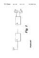
- FIG. 1depicts a typical handset outline schematic
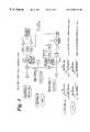
- FIG. 2is a detailed implementation of a PCS1900-AMPS dual mode radio front end
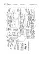
- FIG. 3is a frequency plan of a PCS1900-AMPS dual mode radio front end
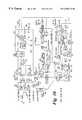
- FIG. 4is a detailed implementation of a PCS1900-UPCS(CT2) dual mode radio front end
- FIG. 5is a frequency plan of a PCS1900-UPCS(CT2) dual mode radio front end
- FIG. 6is a detailed implementation of a PCS1900-Odyssey dual mode radio front end
- FIG. 7is a frequency plan of a PCS1900-Odyssey dual mode radio front end
- FIG. 8is a detailed implementation of a DCS1800-DECT dual mode radio front end
- FIG. 9is a frequency plan of a DCS1800-DECT dual mode radio front end
- FIG. 10is a detailed implementation of a DCS1800-GSM dual mode radio front end
- FIG. 11is a frequency plan of a DCS1800-GSM dual mode radio front end
- FIG. 12is a detailed implementation of a GSM-DECT dual mode radio front end.
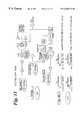
- FIG. 13is a frequency plan of a GSM-DECT dual mode radio front end.
- FIG. 1shows an outline block diagram of a typical cellular radio handset.
- Radio frequency signalsare received and transmitted by the antenna 2 which is connected to a radio front end 4 .
- transmit and receive signalsare converted between radio frequency and base band, whereby digital signal processing means 6 encode the transmit and decode the receive signals and from these can determine the audio signals which are communicated to and from the handset user by loudspeaker 7 and microphone 8 .
- the front endwill typically contain transmit and receive paths which are mixed to an intermediate frequency with a local oscillator. These intermediate frequency signals will be further processed and mixed so that the input and output signals to and from the front end are at baseband and suitable for digital to analogue or analogue to digital conversion, as appropriate, prior to digital signal processing.
- PCS1900operates in the frequency band 1930 to 1990 MHz on the receive downlink to the handset and in the 1850 to 1910 MHz band on the transmit uplink from the handset.
- AMPSoperates in the frequency band 869 to 894 MHz on the receive link from the basestation to the handset and in the 824 to 849 MHz band on the transmit link from the handset to the basestation.
- the PCS1900 handsetoperates either in a transmit mode or in a receive mode: AMPS can operate in both modes simultaneously. For this reason the switch 14 from the antenna 12 has three positions.
- Band pass filter 16 and lowpass filter 18are provided on the input and output lines for the PCS1900 signals whilst a single duplex filter 20 is employed for the input and output lines of the AMPS signals.
- Low noise amplifiers LNA 1 and LNA 2are provided on the input for PCS1900 and AMPS modes. Power amplification is provided by a dual band PA.
- separate band filters 22 and 24are provided from the outputs of the LNAs to the inputs to the mixers 30 and 32 .
- separate IF channel filtersare provided 40 and 42 .
- these filtersare radio frequency surface acoustic wave SAW devices. These SAW devices can be fabricated on quartz, as is known. The advantages provided are such that the separate receive bands can be converted down to an IF and separate channel selection performed, so that over each RF band a large number of channels can be determined.
- the switch 14directs incoming digital PCS1900 signals to the PCS1900 receive path
- the signals from the band select filter 22are passed to a mixer 30 which mixes the received signal with a signal from a synthesised local oscillator 34 to produce an intermediate frequency (IF) signal at 250 MHz which is subsequently amplified by further amplifying means 36 .
- the PCS1900 signalsare then filtered by the 250 MHz IF channel filter, and the filtered IF signal is then passed through a second switching circuit 44 which operates simultaneously with the first switch 14 by a mode control means (not shown).
- the mode control meansidentifies whether the signals are PCS1900 or AMPS modulation and determines in which mode the transceiver is operating.
- the receive signal output from switch 44is fed to an IF amplifier with automatic gain control and a receive signal strength indicator (RSSI) 48 .
- RSSIreceive signal strength indicator
- the signal pathis routed through splitter 50 and the signals are output to a mixer pair 52 and 54 , and after mixing with a quadrature 250 MHz signal derived through switchable division in 56 from a synthesised 500 MHz second local oscillator (2LO), in-phase and quadrature baseband signals are amplified by amplifiers 60 and 62 , to provide output signals at 64 and 66 to be fed to the analogue to digital converters and digital signal processing means (not shown).
- 2LOsynthesised 500 MHz second local oscillator
- the switch 14would feed the signal from the antenna 12 through duplex filter 20 , amplifier LNA 2 , filter 24 to mixer 32 .
- the radio frequency signalis downconverted, using a synthesised local oscillator to a further intermediate frequency (IF) of 125 MHz which is different from that of the digital PCS1900 case.
- This IF signalis subsequently amplified by amplifying means 38 before channel selection by the 125 MHz filter means 42 .
- the 125 MHz IF signalis then passed through the switching circuit 44 .
- the analogue AMPS IF signalis output through the common IF amplifier, which, after amplification and mixing with a quadrature 125 MHz local oscillator signal derived through switchable divider 56 from the second local oscillator (2LO), in-phase and quadrature baseband signals are provided at 64 and 66 to be fed to the analogue to digital converters and digital signal processing means (not shown).
- the custom receive ICuses separate PCS1900 and AMPS LNA/down converters with external SAW image filters. Separate SAW intermediate frequency filters at 250 MHz and 125 MHz are used for PCS1900 and AMPS. For both systems the IF filtering is arranged to be for a single channel.
- the PCS1900 and AMPS baseband signalsare raised to a common 170 MHz intermediate frequency (IF) within a phase lock loop (PLL) which effectively converts the 170 MHz IF to any selected channel in either the PCS1900 or AMPS RF bands.
- the baseband signalsderived from digital signal processing and digital to analogue converters (not shown), are input at ports 70 and 72 , and are amplified by amplifiers 74 and 76 prior to upconversion to the phase lock loop IF of 170 MHz in the quadrature modulator combination of mixers 82 and 84 .
- the upconverted modulation at the 170 MHz IF containing either the PCS1900 or AMPS signalsis filtered 86 and applied to the divider 88 prior to being fed to the PLL phase detector.
- the reference input to the phase detectoris derived by a divider 90 from the prime second local oscillator 58 .
- a charge pump 94feeds from the phase detector to the loop filter 96 , whose output controls the dual-band VCO 98 .
- the phase lock loopis closed and effectively channel tuned by filtering 26 a sample of the preamp 100 output, and downconverting to the 170 MHz IF via the mixer 68 using the same synthesised first local oscillator 34 as for receive.
- This IFis filtered by filter 28 and applied in the loop to the modulator at the 90 degree phase shifter 80 .
- the transmit PLL intermediate frequency filterswill not need to be of high shape factor.
- the first local oscillator signalsare derived from a single dual band voltage controlled oscillator (VCO).
- VCOvoltage controlled oscillator
- Band selection operation of the first local oscillator VCO in the frequency band 1680 to 1740 MHz for the digital PCS1900 case or in the frequency band 994 to 1019 MHz for the analogue AMPS caseis used and four intermediate frequencies (IFs) result.
- the two receive IFshave been arranged to be integer related to the 500 MHz prime second local oscillator (2LO) and to be at frequencies convenient for SAW channel filter implementation.
- the two transmit IFshave been arranged to be the same frequency and reducible by integer division to a 10 MHz reference frequency.
- the quadrature signal local oscillators required to mix the two receive IFs down to basebandare readily derived by division from the 500 MHz 2LO.
- the 1930 to 1990 MHz bandis downconverted to a 250 MHz IF using a channel tuning synthesised 1LO covering the range 1680 to 1740 MHz.
- the channel filtered 250 MHz IFis downconverted to baseband in-phase and quadrature signals using a 250 MHz quadrature local oscillator derived from the 500 MHz 2LO.
- in-phase and quadrature baseband signalsare upconverted to a 170 MHz signal using the 170 MHz IF derived within the phase lock loop by downconversion with the channel tuning receive local oscillator from the RF output.
- the 170 MHz IFis divided and phase locked to a 10 MHz reference and this output controls the transmit RF VCO frequency via a charge pump and loop filter.
- the 869 to 894 MHz bandis downconverted to a 125 MHz IF using a channel tuning synthesised 1LO covering the range 994 to 1019 MHz.
- the channel filtered 125 MHz IFis downconverted to baseband in-phase and quadrature signals using a 125 MHz quadrature local oscillator derived from the 500 MHz 2LO.
- the AMPS transmit stateis similar to the PCS1900 in that in-phase and quadrature baseband signals are upconverted to a 170 MHz signal using a 170 MHz IF derived within the phase lock loop by downconversion with the channel tuning receive local oscillator from the RF output.
- the 170 MHz IFis divided and phase locked to a 10 MHz reference and this output controls the transmit RF VCO frequency via a charge pump and loop filter.
- a feature of the 1LO synthesised frequency generationis that the transmit and receive local oscillator tuning bands are arranged to overlap by using different transmit and receive IFs. In this way the overall tuning range of the 1LO for PCS1900 can be constrained such that transmit to receive switching can be achieved in an allowable time. It is a requirement in the AMPS case for the transmit and receive first local oscillators to tune the same range and channel as the AMPS radio simultaneously transmits and receives. In this dual-mode it has been arranged that for the PCS1900 case the transmit and receive first local oscillators exactly overlap also.
- the two receive quadrature second local oscillator signalsare derived from the prime 500 MHz 2LO as follows.
- the prime second local oscillatorprovides a synthesised 500 MHz signal 58 which is fed to a switchable divide by two or divide by four divider 56 resulting in a 250 MHz or 125 MHz local oscillator.
- the 500 MHzis divided by 50 in divider 78 resulting in the 10 MHz reference.
- the local oscillatorsreceive a 13.0 MHz signal which is processed through dividers set by control signals: this allows the local oscillators to operate in the PCS1900 and the AMPS transmit or receive modes.
- band control meansoperable to adjust the local oscillator frequency in response to channel detection means which detect the channel employed in any communication.
- channel detection meansIn the case of the mobile initiating a call then the channel detection means will be able to detect which channels are available and be able to effect the control switches for the PCS1900-AMPS circuits as appropriate.
- the programmable dividersoperate under the control of data, clock and enable commands.
- the prime second local oscillator 2LOproduces a fixed frequency signal at 500 MHz, and employs a feedback path to ensure that the frequency is maintained.
- the required frequencies 250, 125 and 10 MHzcan be derived from the 13.0 MHz reference, as can the required first local oscillator frequencies.
- the synthesiser first local oscillatoraccomplishes dual mode operation by having a dual band local oscillator which tunes a single band for transmit and receive either 1680 to 1740 MHz for the PCS1900 or 994 to 1019 MHz for AMPS transmit and receive.
- the 1LOtunes in 200 kHz spaced channels and for AMPS in 30 kHz channels, defined by the by R/Q divider on the reference to the phase lock loop, and the programmable divider.
- FIG. 4there is shown a second embodiment of the present invention, comprising a dual mode radio front end for the reception of both digital cellular PCS1900 signals and digital cordless UPCS(CT2) signals.
- UPCS(CT2)operates in the frequency band 1920 to 1930 MHz and in the same frequency channel on the receive and transmit links by way of time division duplexing.
- the PCS1900 handsetoperates either in a transmit mode or in a receive mode and uses frequency division duplex: UPCS(CT2) also operates in transmit or receive mode but uses the same frequecy channel with time division duplex. For this reason the switch 14 from the antenna 12 has three positions.
- Band pass and lowpass filters 16 and 18are provided on the input and output lines for the PCS signals whilst a second switch 106 and single RF band filter 20 are employed for UPCS(CT2) signals.
- Low noise amplifiers LNA 1 and LNA 2are provided on the input lines respectively. Power amplification is provided by a single band power amplifier PA continuously covering the PCS1900 band so that the UPCS(CT2) band which falls between the PCS1900 transmit and receive bands is also covered.
- separate band filters 22 and 24are provided from the outputs of the LNAs to the inputs to the mixers 30 and 32 .
- separate IF channel filtersare provided 40 and 42 .
- these filtersare radio frequency surface acoustic wave SAW devices.
- the receive path for the digital PCS1900 signalsis as described for the first embodiment).
- the mode control meansidentifies whether the signals are PCS1900 or UPCS(CT2) modulation and determines in which mode the transceiver is operating.
- the switch 14would feed the signal from the antenna 12 through band filter 20 , amplifier LNA 2 , filter 24 to mixer 32 .
- the radio frequency signalis downconverted, using a synthesised local oscillator to a further intermediate frequency (IF) of 125 MHz which is different from that of the digital PCS1900 case.
- This IF signalis subsequently amplified by amplifying means 38 before channel selection by the 125 MHz filter means 42 .
- the 125 MHz IF signalis then passed through the switching circuit 44 .
- the UPCS IF signalis output through the common IF amplifier, which, after amplification and mixing with a quadrature 125 MHz local oscillator signal derived through switchable divider 56 from the second local oscillator (2LO) 58 , in-phase and quadrature baseband signals are provided at 64 and 66 to be fed to the analogue to digital converters and digital signal processing means (not shown).
- the custom receive ICuses separate PCS1900 and UPCS LNA/down converters with external SAW image filters. Separate SAW intermediate frequency filters at 250 MHz and 125 MHz are used for PCS1900 and UPCS. For both systems the IF filtering is arranged to be for a single channel.
- the PCS1900 and UPCS baseband signalsare raised to separate 170 and 125 MHz intermediate frequency (IF) within a phase lock loop (PLL) which effectively converts the IF to any selected channel in either the PCS1900 or UPCS(CT2) RF bands.
- the baseband signalsderived from digital signal processing and digital to analogue converters (not shown), are input at ports 70 and 72 , and are amplified by amplifiers 74 and 76 prior to upconversion to the phase lock loop IF 170 or 125 Mhz in the quadrature modulator combination of mixers 82 and 84 .
- the upconverted modulation at the 170 MHz IF containing either the PCS1900 or UPCS signalsis filtered 86 and applied to the divider 88 prior to being fed to the PLL phase detector.
- the reference input to the phase detectoris derived by a divider 90 from the prime second local oscillator 58 .
- a charge pump 94feeds from the phase detector to the loop filter 96 , whose output controls the dual-band VCO 98 .
- the phase lock loopis closed and effectively channel tuned by filtering 26 a sample of the preamplifier 100 output, and downconverting to the 170 or 125 MHz IF via the mixer 68 using the same synthesised first local oscillator 34 as for receive.
- This IFis filtered 28 and applied in the loop to the modulator at the 90 degree phase shifter 80 .
- the transmit PLL intermediate frequency filterswill not need to be of high shape factor.
- the first local oscillator signalsare derived from a single dual band voltage controlled oscillator (VCO).
- VCOvoltage controlled oscillator
- Band selection operation of the first local oscillator VCO in the frequency band 1680 to 1740 MHz for the digital PCS1900 case or in the frequency band 1795 to 1805 MHz for the UPCS(CT2) caseis used and four intermediate frequencies (IFs) result.
- the two receive IFshave been arranged to be integer related to the 500 MHz prime second local oscillator (2LO) and to be at frequencies convenient for SAW channel filter implementation.
- the two transmit IFshave been arranged to be at frequencies reducible by integer division to a 10 or 12.5 MHz reference frequency, both themselves derived by integer division from the 500 Mhz prime second local oscillator (2LO).
- the quadrature signal local oscillators required to mix the two receive IFs down to basebandare readily derived by division from the 500 MHz 2LO.
- the 1930 to 1990 MHz bandis downconverted to a 250 MHz IF using a channel tuning synthesised 1LO covering the range 1680 to 1740 MHz.
- the channel filtered 250 MHz IFis downconverted to baseband in-phase and quadrature signals using a 250 MHz quadrature local oscillator derived from the 500 MHz 2LO.
- in-phase and quadrature baseband signalsare upconverted to a 170 MHz signal using the 170 MHz IF derived within the phase lock loop by downconversion with the channel tuning receive local oscillator from the RF output.
- the 170 MHz IFis divided and phase locked to a 10 MHz reference and this output controls the transmit RF VCO frequency via a charge pump and loop filter.
- the 1920 to 1930 MHz bandis downconverted to a 125 MHz IF using a channel tuning synthesised 1LO covering the range 1795 to 1805 MHz.
- the channel filtered 125 MHz IFis downconverted to baseband in-phase and quadrature signals using a 125 MHz quadrature local oscillator derived from the 500 MHz 2LO.
- the UPCS(CT2) transmit stateis similar to the PCS1900 in that in-phase and quadrature baseband signals are upconverted to a 125 MHz signal using a 125 MHz IF derived within the phase lock loop by downconversion with the channel tuning receive local oscillator from the RF output.
- the 125 MHz signalis divided and phase locked to a 12.5 MHz reference and this output controls the transmit RF VCO frequency via a charge pump and loop filter.
- a feature of the 1LO synthesised frequency generationis that the transmit and receive local oscillator tuning bands are arranged to overlap by using different transmit and receive IFs. In this way the overall tuning range of the 1LO for PCS1900 can be constrained such that transmit to receive switching can be achieved in an allowable time. It is a requirement in the UPCS(CT2) case for the transmit and receive first local oscillators to tune the same range and channel, as the UPCS(CT2) radio uses the same air frequency for uplink and downlink.
- the 1LOis arranged to have a 1680 to 1805 MHz tuning range to cover the requirements of both PCS1900 and UPCS(CT2). In this dual-mode it has been arranged that for the PCS1900 case the transmit and receive first local oscillators exactly overlap also.
- the two receive quadrature second local oscillator signalsare derived from the prime 500 MHz 2LO as follows.
- the prime second local oscillatorprovides a synthesised 500 MHz signal which is fed to a switchable divide by two or divide by four divider 56 resulting in a 250 MHz or 125 MHz local oscillator.
- the 500 MHzis divided by 50 in divider 90 resulting in the 10 MHz reference, or it is divided by 40 in divider 90 to give a 12.5 MHz reference.
- the local oscillatorsreceive a 13 MHz signal which is processed through dividers set by control signals: this allows the local oscillators to operate in the PCS1900 and UPCS(CT2) modes.
- the channel detection meanswill be able to detect which channels are available and be able to effect the control switches for the PCS1900-UPCS(CT2) circuits as appropriate.
- the programmable dividersoperate under the control of data, clock and enable commands.
- the prime second local oscillator 2LOproduces a fixed frequency signal at 500 MHz, and employs a feedback path to ensure that the frequency is maintained. By these means the required frequencies 250, 125, 12.5 and 10 MHz can be derived from the 13 MHz reference, as can the required first local oscillator frequencies.
- the synthesised first local oscillatoraccomplishes dual mode operation by having a local oscillator which tunes a single band from 1680 to 1805 MHz which covers the PCS requirement for transmit and receive of 1680 to 1740 MHz and the UPCS(CT2) requirement of 1795 to 1805 MHz.
- the 1LOtunes in 200 kHz spaced channels and for UPCS(CT2) in 100 kHz channels, defined by the by R/O divider on the reference to the phase lock loop, and the programmable divider.
- FIG. 6there is shown one embodiment of the present invention, comprising a dual mode radio front end for the reception of both digital PCS1900 signals and digital ODYSSEY signals.
- ODYSSEYoperates in the frequency band 2483.5 to 2500.0 MHz on the receive link from the satellite to the handset and in the 1745.5 to 1761.5 MHz band on the transmit link from the handset to the satellite.
- the PCS1900 handsetoperates either in a transmit mode or in a receive mode: ODYSSEY can operate in both modes simultaneously. For this reason the switch 14 from the antenna 12 has three positions.
- Band pass filters 16 and lowpass filter 18are provided on the input and output lines for the PCS1900 signals whilst a single duplex filter 20 is employed for the input and output lines of the ODYSSEY signals.
- Low noise amplifiers LNA 1 and LNA 2are provided at the receive inputs.
- a separate LNA downconverter GaAs MMICis provided for the ODYSSEY mode to meet a noise figure requirement not achievable in silicon.
- separate band filters 22 and 24are provided from the outputs of the LNAs to the inputs to the mixers 30 and 32 .
- separate IF channel filtersare provided 40 and 42 .
- these filtersare radio frequency surface acoustic wave SAW devices. The advantages provided are such that the separate receive bands can be converted down to an IF and separate channel selection performed, so that over each RF band a large number of channels can be determined.
- the mode control meansidentifies whether the signals are PCS1900 or ODYSSEY modulation and determines in which mode the transceiver is operating.
- the switch 14would feed the signal from the antenna 12 through duplex filter 20 , amplifier LNA 2 , filter 24 to mixer 32 .
- the radio frequency signalis downconverted, using an output from the additional synthesised local oscillator to a further intermediate frequency (IF) of 225 MHz, which although having the same centre frequency as PCS1900 case, has a channel bandwidth commensurate with the ODYSSEY mode.
- This IF signalis subsequently amplified by amplifying means 38 before channel selection by the 225 MHz filter means 42 .
- the 225 MHz IF signalis then passed through the switching circuit 44 .
- the ODYSSEY IF signalis output through the common IF amplifier, which, after amplification and mixing with a quadrature 225 MHz local oscillator signal derived through switchable dividers 56 and 68 from the second local oscillator (2LO), in-phase and quadrature baseband signals are provided at 64 and 66 to be fed to the analogue to digital converters and digital signal processing means (not shown).
- PCS1900uses the custom silicon LNA/down-converter on the receive IC with external SAW image filters. While ODYSSEY uses a seperate custom GaAs MMIC for the LNA/down-converter. For both systems the IF filtering is arranged to be for a single channel.
- the PCS1900 and ODYSSEY baseband signalsare raised to 135 MHz intermediate frequencies (IFs) in both cases.
- These baseband signalsderived from digital signal processing and digital to analogue converters (not shown), are input at ports 70 and 72 , and are amplified by amplifiers 74 and 76 prior to upconversion in the quadrature modulator combination of mixers 82 and 84 , using one of two local oscillators, at 135 MHz for PCS1900 and ODYSSEY, derived through switchable division in 78 and 80 from the 1350 MHz synthesised second local oscillator.
- the upconverted IF containing either the PCS1900 or ODYSSEY signals at 135 MHzis combined 100 and applied to the switch 286 and then to the transmit IF filter combination 288 and 290 in order to select the required bandwidth of IF. Either of the two IFs are then upconverted in mixers 292 or 294 to the PCS1900 transmit band at 1850 to 1910 MHz and the ODYSSEY transmit band at 1745.5 to 1761.5 MHz.
- the respective signalsare RF band filtered by 226 and 228 prior to power amplification and then fed to the antenna via separate filters and switch 14 .
- the first local oscillator signalsare derived from two 1LO synthesisers, themselves referenced to a 13.0 MHz crystal reference (not shown).
- the two receive IFshave been arranged to be the same frequency and integer related to the 1350 MHz prime second local oscillator (2LO) and to be at frequencies convenient for separate SAW channel filter implementation.
- the two transmit IFshave been arranged to be the same frequency and an integer function of the prime second local oscillator by division and mixing.
- the prime second local oscillatoris also referenced to the 13.0 Mhz crystal reference.
- the quadrature signal local oscillators required to mix the two receive IFs down to basebandare readily derived by integer division from the 1350 MHz 2LO.
- the 1930 to 1990 MHz bandis downconverted to a 225 MHz IF using a channel tuning synthesised 1LO covering the range 1705 to 1765 MHz.
- the channel filtered 225 MHz IFis downconverted to baseband in-phase and quadrature signals using a 225 MHz quadrature local oscillator derived from the 1350 MHz 2LO.
- in-phase and quadrature baseband signalsare upconverted to a 135 MHz IF using a 135 MHz quadrature local oscillator derived from the 1350 MHz 2LO.
- the filtered 135 MHz IFis upconverted to the 1850 to 1910 MHz band using a channel tuning synthesised 1LO covering the range 1715 to 1775 MHz.
- the 2483.5 to 2500.0 MHz bandis downconverted to a 225 MHz IF using a channel tuning additional synthesised 1LO covering the range 2258.5 to 2275.0 MHz.
- the channel filtered 225 MHz IFis downconverted to baseband in-phase and quadrature signals using a 225 MHz quadrature local oscillator derived from the 1350 MHz 2LO.
- the ODYSSEY transmit stateis similar to the PCS1900 in that in-phase and quadrature baseband signals are upconverted to a 135 MHz signal using 135 MHz quadrature local oscillator derived from the 1350 MHz 2LO.
- the filtered 135 MHz IFis upconverted to the 1610.0 to 1626.5 MHz band using a channel tuning synthesised 1LO covering the range 1745.0 to 1761.5 MHz. It can be seen that the ODYSSEY transmit 1LO has been arranged to be provided by the same 1LO as that of PCS1900.
- a feature of the 1LO synthesised frequency generationis that the PCS1900 transmit and receive local oscillator tuning bands are arranged to overlap by using different transmit and receive IFs. In this way the overall tuning range of the 1LO for PCS1900 can be constrained such that transmit to receive switching of the 1LO can be achieved in an allowable time. In the ODYSSEY case the transmit and receive first local oscillators are separate due to the 873.5 MHz duplex spacing.
- the two receive quadrature second local oscillator signalsare derived from the prime 1350 MHz 2LO as follows.
- the prime second local oscillatorprovides a synthesised 1350 MHz signal which is fed to a divide by three divider 68 resulting in a 450 MHz feed to the divide by two divider 56 , which feeds quadrature 225 MHz oscillator signal to the mixers 52 and 54 .
- the two transmit quadrature second local oscillator signalsare derived from the prime 1350 MHz 2LO by a divide by five divider 78 resulting in a 270 MHz feed to the divide by two divider 80 , which feeds quadrature 135 MHz oscillator signal to the mixers 82 and 84 .
- the local oscillatorsreceive a 13.0 MHz signal which is processed through dividers set by control signals: this allows the local oscillators to operate in the PCS1900 or ODYSSEY transmit or receive modes
- the channel detection meanswill be able to detect which channels are available and be able to effect the control switches for the PCS1900-ODYSSEY circuits as appropriate.
- the programmable dividersoperate under the control of data, clock and enable commands.
- the prime second local oscillator 2LOproduces a fixed frequency signal at 1350 MHz, and employs a feedback path to ensure that the frequency is maintained. By these means the required frequencies 225 and 135 MHz can be derived from the 13.0 MHz reference, as can the required first local oscillator frequencies.
- the synthesised first local oscillatoraccomplishes operation for PCS1900 transmit and receive together with ODYSSEY transmit by having a local oscillator which tunes a single band 1705 to 1775 MHz.
- the 1LOtunes in 200 kHz spaced channels, defined by the by R/Q divider on the reference to the phase lock loop, and the programmable divider.
- a separate 1LO synthesiseris used tuning 2258.5 to 2275.0 MHz.
- DCS1800operates in the frequency band 1805 to 1880 MHz on the receive downlink to the handset and in the 1710 to 1785 MHz band on the transmit uplink from the handset.
- DECToperates in the frequency 1881.792 to 1897.344 Mhz and in the same frequency channel on the handset transmit and receive links by way of time division duplexing.
- the DCS1800 handsetoperates either in a transmit mode or in a receive mode and uses frequency division duplex: DECT also operates in transmit or receive mode but uses the same frequency channel with time division duplex. For this reason the switch 14 from the antenna 12 has three positions.
- Band pass filters 16 and low pass filter 18are provided on the input and output lines for the DCS1800 signals whilst a second switch 306 and single RF band filter 20 are employed for DECT signals.
- Low noise amplifiers LNA 1 and LNA 2are provided on the input respectively. Power amplification is provided by a dual band PA.
- separate band filters 22 and 24are provided from the outputs of the LNAs to the inputs to the mixers 30 and 32 .
- separate IF channel filtersare provided 40 and 42 .
- these filtersare radio frequency surface acoustic wave SAW devices.
- the signals from the band select filter 22are passed to a mixer 30 which mixes the received signal with a signal from a synthesised local oscillator 34 to produce an intermediate frequency (IF) signal at 225 MHz which is subsequently amplified by further amplifying means 36 .
- the DCS1800 signalsare then filtered by the 225 MHz GSM IF channel filter (the DCS1800 modulation protocol is the same as that of GSM so the filter is a GSM channel filter), and the filtered IF signal is then passed through a second switching circuit 44 which operates simultaneously with the first switch 14 by a mode control means (not shown).
- the mode control meansidentifies whether the signals are DCS1800 or DECT modulation and determines in which mode the transceiver is operating.
- the receive signal output from switch 44is fed to an IF amplifier with automatic gain control and a receive signal strength indicator (RSSI) 48 .
- RSSIreceive signal strength indicator
- the signal pathis routed through splitter 50 and the signals are output to a mixer pair 52 and 54 , and after mixing with a quadrature 225 MHz signal derived through switchable division in 56 from a synthesised 450 MHz second local oscillator (2LO), in-phase and quadrature baseband signals are amplified by amplifiers 60 and 62 , to provide output signals at 64 and 66 to be fed to the analogue to digital converters and digital signal processing means (not shown).
- LOreceive signal strength indicator
- the switch 14would feed the signal from the antenna 12 through filter 20 , amplifier LNA 2 , filter 24 to mixer 32 .
- the radio frequency signalis downconverted, using a synthesised local oscillator to the intermediate frequency (IF) of 110.592 MHz which is different from that of the DCS1800 case.
- This IF signalis subsequently amplified by amplifying means 38 before channel selection by the 110.592 MHz filter means 42 .
- the DECT IF signalis output through the common IF amplifier , which, after amplification and mixing with a quadrature local oscillator signal of 110.592 MHz derived through divider 56 from the dual frequency second local oscillator (2LO), in-phase and quadrature baseband signals are provided at 64 and 66 to be fed to the analogue to digital converters and digital signal processing means (not shown).
- the custom receive ICuses separate DCS1800 and DECT LNA/down converters with external SAW image filters. Separate SAW intermediate frequency filter at 225 and 110.592 Mhz are used for DCS1800 and DECT. For both systems the IF filtering is arranged to be for a single channel.
- the DCS1800 and DECT baseband signalsare raised to intermediate frequencies (IFs) at 130 and 110.592 MHz within a phase lock loop (PLL) which effectively converts the IF to any selected channel in either the DCS1800 or DECT RF bands.
- the baseband signalsderived from digital signal processing and digital to analogue converters (not shown), are input at ports 70 and 72 , and are amplified by amplifiers 74 and 76 prior to upconversion to the phase lock loop IF of 130 or 110.592 MHz in the quadrature modulator combination of mixers 82 and 84 .
- the upconverted modulation at the IF containing either the DCS1800 or DECT signalsis filtered 86 and applied to the divider 88 prior to being fed to the PLL phase detector.
- the reference input to the phase detectoris derived by a divider 90 from the switched 108 dual reference oscillators (not shown).
- a charge pump 94feeds from the phase detector to the loop filter 96 , whose output controls the dual-band VCO 98 .
- the phase lock loopis closed and effectively channel tuned by filtering 26 a sample of the preamp 100 output, and downconverting to the 130 or 110.592 MHz IF via the mixer 68 using the same synthesised first local oscillator 34 as for receive.
- This IFis filtered 28 and applied in the loop to the modulator at the 90 degree phase shifter 80 .
- the transmit PLL intermediate frequency filterswill not need to be of high shape factor and can be arranged to bracket both IFs.
- the first local oscillator signalsare derived from a single dual band voltage controlled oscillator (VCO).
- VCOvoltage controlled oscillator
- Band selection operation of the dual band first local oscillator VCO in the frequency band 1580 to 1655 MHz for the DCS1800 case or in the frequency band 1771.200 to 1786.752 MHz for the DECT caseis used and four intermediate frequencies (IFs) result.
- the two receive IFshave been arranged to be integer related to the 450/442.368 MHz dual prime second local oscillator (2LO) and to be at frequencies convenient for SAW channel filter implementation.
- the two transmit IFshave been arranged to be at frequencies reducible by integer division to a 13 or 13.824 MHz reference frequency.
- the quadrature signal local oscillators required to mix the two receive IFs down to basebandare readily derived by division from the 450/442.368 MHz 2LO.
- the dual frequency prime 2LOis switched to the required frequency for DCS1800 or DECT and respectively referenced to 13.0 or 13.824 MHz.
- the 1805 to 1880 MHz bandis downconverted to a 225 MHz IF using a channel tuning synthesised 1LO covering the range 1580 to 1655 MHz.
- the channel filtered 225 MHz IFis downconverted to baseband in-phase and quadrature signals using a 225 MHz quadrature local oscillator derived from the dual frequency 2LO when programmed for the 450 MHz DCS1800 mode.
- in-phase and quadrature baseband signalsare upconverted to a 130 MHz signal using the 130 MHz IF derived within the phase lock loop by downconversion with the channel tuning receive local oscillator from the RF output.
- the 130 MHz IFis divided and phase locked to a 13 MHz reference and this output controls the transmit RF VCO frequency via a charge pump and loop filter.
- the 1881.792 to 1897.344 MHz bandis downconverted to a 110.592 MHz IF using a channel tuning synthesised 1LO covering the range 1771.200 to 1786.752 MHz.
- the channel filtered 110.592 MHz IFis downconverted to baseband in-phase and quadrature signals using a 110.592 MHz quadrature local oscillator oscillator derived from the dual frequency 2LO when programmed for the 442.368 MHz DECT mode.
- the DECT transmit stateis similar to the DCS1800 in that in-phase and quadrature baseband signals are upconverted to a 110.592 MHz signal using a 110.592 MHz IF derived within the phase lock loop by downconversion with the channel tuning receive local oscillator from the RF output.
- the 110.592 MHz IFis divided and phase locked to a 13.824 MHz reference and this output controls the transmit RF VCO frequency via a charge pump and loop filter.
- a feature of the 1LO synthesised frequency generationis that in the DCS1800 mode the transmit and receive local oscillator tuning bands are arranged to exactly overlap by using different transmit and receive IFs. In this way the tuning range of the 1LO can be constrained such that retuning the 1LO between transmit and receive is unnecessary. It is a requirement in the DECT mode for the transmit and receive first local oscillators to tune the same frequency range and channel, as the DECT radio uses the same air frequency for uplink and downlink.
- the 1LOis arranged to have two frequency bands at 1771.200 to 1786.752 MHz to cover the requirements of DECT and 1580 to 1655 MHz to cover DCS1800.
- the two receive quadrature second local oscillator signalsare derived from the prime 2LO as follows.
- the prime second local oscillatorprovides a synthesised 450 or 442.368 MHz signal 58 which is fed to a switchable divide by two or four divider 56 resulting in a 225 or 110.592 MHz local oscillator.
- the 13 MHz referenceis divided by 1 in divider 90 resulting in the 13 MHz reference.
- the 13.824 MHzis divided by 1 in divider 90 resulting in the 13.824 MHz reference (the divider will already be a part of the integrated circuit and can be set to divide by 1).
- the local oscillatorsreceive a 13.0 or 13.824 MHz signal which is processed through dividers set by control signals: this allows the local oscillators to operate in the DCS1800 or the DECT modes.
- band control meansoperable to adjust the local oscillator frequency in response to channel detection means which detect the channel employed in any communication.
- channel detection meansIn the case of the mobile initiating a call then the channel detection means will be able to detect which channels are available and be able to effect the control switches for the DCS1800-DECT circuits as appropriate.
- the programmable dividersoperate under the control of data, clock and enable commands.
- the prime second local oscillator 2LOproduces a two frequencies at 450 and 442.368 MHz, and employs a feedback path to ensure that the frequency is maintained.
- the required frequencies 225, 130, and 110.592 MHzcan be derived from the 13.0 and 13.824 MHz references, as can the required first local oscillator frequencies.
- the synthesised first local oscillatoraccomplishes dual mode operation by having a dual band local oscillator which tunes dual bands; 1580 to 1655 MHz for DCS1800 or 1771.200 to 1786.752 MHz for DECT.
- the 1LOtunes in 200 kHz spaced channels and in the DECT mode 1.728 MHz spaced channels, defined by the by R/Q divider on the reference to the phase lock loop, and the programmable divider.
- GSMoperates in the frequency band 925 to 960 MHz on the receive link from the basestation to the handset and in the 880 to 915 MHz band on the transmit link from the handset to the basestation.
- the DCS1800 and GSM handsetsboth operate in either a transmit mode or in a receive mode. For this reason the switch 14 from the antenna 12 has four positions.
- Band pass filters 16 , 18are provided on the input and output lines for the DCS1800 signals along with similar filters 20 and 406 for GSM.
- Low noise amplifiers LNAare provided on the input and output lines respectively. Power amplification is provided by a dual band power amplifier PA.
- separate band filters 22 and 24are provided from the outputs of the LNAs to the inputs to the mixers 30 and 32 .
- the different system signalsare applied to a switch which selects either signal to apply to the common channel IF filter 40 .
- this filteris a radio frequency surface acoustic wave SAW device.
- the switch 414directs incoming digital DCS1800 signals to the DCS1800 receive path through the band filter 16 and to the LNA 1 and band filter 22
- the signals from the band select filter 22are passed to a mixer 30 which mixes the received signal with a signal from a synthesised local oscillator 34 to produce an intermediate frequency (IF) signal at 225 MHz which is subsequently amplified by further amplifying means 36 .
- the DCS1800 signalsare then selected by switch 44 which operates simultaneously with the first switch 14 by a mode control means (not shown).
- the mode control meansidentifies whether the signals are DCS1800 or GSM modulation and determines in which mode the transceiver is operating.
- the signalis then filtered by the 225 MHz IF channel filter.
- the receive signal output from IF filter 40is fed to an IF amplifier with automatic gain control and a receive signal strength indicator (RSSI) 48 .
- RSSIreceive signal strength indicator
- the signal pathis routed through splitter 50 and the signals are output to a mixer pair 52 and 54 , and after mixing with a quadrature 225 MHz signal derived through division in 56 from a synthesised 450 MHz second local oscillator (2LO), in-phase and quadrature baseband signals are amplified by amplifiers 60 and 62 , to provide output signals at 64 and 66 to be fed to the analogue to digital converters and digital signal processing means (not shown).
- 2LOsynthesised 450 MHz second local oscillator
- the switch 14would feed the signal from the antenna 12 through filter 20 , amplifier LNA 2 , filter 24 to mixer 32 .
- the radio frequency signalis downconverted, using a synthesised local oscillator to the same intermediate frequency (IF) of 225 MHz as that of the DCS1800 case.
- This IF signalis subsequently amplified by amplifying means 38 before being selected by switch 44 and applied to the channel selection filter 40 .
- the GSM IF signalis output through the common IF amplifier, which, after amplification and mixing with a quadrature 225 MHz local oscillator signal derived through divider 56 from the second local oscillator (2LO), in-phase and quadrature baseband signals are provided at 64 and 66 to be fed to the analogue to digital converters and digital signal processing means (not shown).
- the custom receive ICuses separate DCS1800 and GSM LNA/down converters with external SAW image filters.
- a common SAW intermediate frequency filter at 225 MHzis used for DCS1800 and GSM.
- the IF filteringis arranged to be for a single channel.
- the DCS1800 and GSM baseband signalsare raised to intermediate frequencies (IFs) at 135 and 270 MHz within a phase lock loop (PLL) which effectively converts the IF to any selected channel in either the DCS1800 or GSM RF bands.
- IFsintermediate frequencies
- PLLphase lock loop
- the baseband signalsderived from digital signal processing and digital to analogue converters (not shown), are input at ports 70 and 72 , and are amplified by amplifiers 74 and 76 prior to upconversion to the phase lock loop IF of 135 or 270 MHz in the quadrature modulator combination of mixers 82 and 84 .
- the upconverted modulation at the IF containing either the DCS1800 or GSM signalsis filtered 86 and applied to the divider 88 prior to being fed to the PLL phase detector.
- the reference input to the phase detectoris derived by a divider 90 from the prime second local oscillator 58 .
- a charge pump 94feeds from the phase detector to the loop filter 96 , whose output controls the dual-band VCO 98 .
- the phase lock loopis closed and effectively channel tuned by filtering 26 a sample of the preamp 100 output, and downconverting to the 135 or 270 MHz IF via the mixer 68 using the same synthesised first local oscillator 34 as for receive.
- This IFis filtered 28 and applied in the loop to the modulator at the 90 degree phase shifter 80 .
- the transmit PLL intermediate frequency filterswill not need to be of high shape factor and can be arranged to bracket both IFs.
- FIGS. 10 and 11it can be seen from FIGS. 10 and 11 that all the required local oscillator frequencies are derived from two voltage controlled oscillators, referenced via two phase lock loops to 13.0 MHz.
- the first local oscillator signalsare derived from a single dual band voltage controlled oscillator (VCO).
- VCOvoltage controlled oscillator
- Band selection operation of the dual band first local oscillator VCO in the frequency band 1575 to 1650 MHz for the DCS1800 case or in the frequency band 1150 to 1185 MHz for the GSM caseis used and three intermediate frequencies (IFs) result.
- the two receive IFshave been arranged to be integer related to the 450 MHz prime second local oscillator (2LO) and to be at frequencies convenient for SAW channel filter implementation.
- the two transmit IFshave been arranged to be at frequencies reducible by integer division to a 45 MHz reference frequency.
- the quadrature signal local oscillators required to mix the two receive IFs down to basebandare readily derived by division from the 450 MHz 2LO.
- the 1805 to 1880 MHz bandis downconverted to a 225 MHz IF using a channel tuning synthesised 1LO covering the range 1575 to 1655 MHz.
- the channel filtered 225 MHz IFis downconverted to baseband in-phase and quadrature signals using a 225 MHz quadrature local oscillator derived from the 450 MHz 2LO.
- in-phase and quadrature baseband signalsare upconverted to a 135 MHz signal using the 135 MHz IF derived within the phase lock loop by downconversion with the channel tuning receive local oscillator from the RF output.
- the 135 MHz IFis divided and phase locked to a 45 MHz reference and this output controls the transmit RF VCO frequency via a charge pump and loop filter.
- the 925 to 960 MHz bandis downconverted to a 225 MHz IF using a channel tuning synthesised 1LO covering the range 1150 to 1185 MHz.
- the channel filtered 225 MHz IFis downconverted to baseband in-phase and quadrature signals using a 225 MHz quadrature local oscillator derived from the 450 MHz 2LO.
- the GSM transmit stateis similar to the DCS1800 in that in-phase and quadrature baseband signals are upconverted to a 270 MHz signal using a 270 MHz IF derived within the phase lock loop by downconversion with the channel tuning receive local oscillator from the RF output.
- the 270 MHz IFis divided and phase locked to a 45 MHz reference and this output controls the transmit RF VCO frequency via a charge pump and loop filter.
- a feature of the 1LO synthesised frequency generationis that the transmit and receive local oscillator tuning bands are arranged to overlap by using different transmit and receive IFs. In this way the overall tuning range of the 1LO for DCS1800 can be constrained such that transmit to receive switching can be achieved in an allowable time. In the GSM case it has been arranged that the transmit and receive first local oscillators exactly overlap.
- the two receive quadrature second local oscillator signalsare derived from the prime 450 MHz 2LO as follows.
- the prime second local oscillatorprovides a synthesised 450 MHz signal which is fed to a switchable divide by two divider 56 resulting in a 225 MHz local oscillator.
- the 450 MHzis divided by 10 in divider 90 resulting in the 45 MHz reference.
- the local oscillatorsreceive a 13 MHz signal which is processed through dividers set by control signals: this allows the local oscillators to operate in the DCS1800 Transmit and receive mode, or the GSM mode.
- band control meansoperable to adjust the local oscillator frequency in response to channel detection means which detect the channel employed in any communication.
- channel detection meansIn the case of the mobile initiating a call then the channel detection means will be able to detect which channels are available and be able to effect the control switches for the DCS1800-GSM circuits as appropriate.
- the programmable dividersoperate under the control of data, clock and enable commands.
- the prime second local oscillator 2LOproduces a fixed frequency signal at 450 MHz, and employs a feedback path to ensure that the frequency is maintained.
- the required frequencies 225, 270, 135 and 45 MHzcan be derived from the 13 MHz reference, as can the required first local oscillator frequencies.
- the synthesiser first local oscillatoraccomplishes dual mode operation by having a dual band local oscillator which tunes a single band for transmit and receive either 1575 to 1655 MHz for the DCS1800 or 1150 to 1185 MHz for GSM transmit and receive.
- the 1LOtunes in 200 kHz spaced channels, defined by the by R/Q divider on the reference to the phase lock loop, and the programmable divider.
- FIG. 12there is shown one embodiment of the present invention, comprising a dual mode radio front end for the reception of both digital cellular GSM signals and digital cordless DECT signals.
- DECToperates in the frequency 1881.792 to 1897.344 MHz and in the same frequency channel on the handset transmit and receive links by way of time division duplexing.
- the GSM handsetoperates either in a transmit mode or in a receive mode and uses frequency division duplex: DECT also operates in transmit or receive mode but uses the same frequency channel with time division duplex. For this reason the switch 14 from the antenna 12 has three positions.
- Band pass filters 16 and low pass filter 18are provided on the input and output lines for the GSM signals whilst a second switch 506 and single RF band filter 20 are employed for DECT signals.
- Low noise amplifiers LNA 1 and LNA 2are provided on the input respectively. Power amplification is provided by a dual band PA.
- separate band filters 22 and 24are provided from the outputs of the LNAs to the inputs to the mixers 30 and 32 .
- separate IF channel filtersare provided 40 and 42 .
- these filtersare radio frequency surface acoustic wave SAW devices.
- the switch 14when the switch 14 directs incoming digital GSM signals to the GSM receive path, the signals from the band select filter 22 are passed to a mixer 30 which mixes the received signal with a signal from a synthesised local oscillator 34 to produce an intermediate frequency (IF) signal at 225 MHz which is subsequently amplified by further amplifying means 36 .
- the GSM signalsare then filtered by the 225 MHz IF channel filter, and the filtered IF signal is then passed through a second switching circuit 44 which operates simultaneously with the first switch 14 by a mode control means (not shown).
- the mode control meansidentifies whether the signals are GSM or DECT modulation and determines in which mode the transceiver is operating.
- the receive signal output from switch 44is fed to an IF amplifier with automatic gain control and a receive signal strength indicator (RSSI) 48 .
- RSSIreceive signal strength indicator
- the signal pathis routed through splitter 50 and the signals are output to a mixer pair 52 and 54 , and after mixing with a quadrature 225 MHz signal derived through switchable division in 56 from a synthesised 450 MHz second local oscillator (2LO), in-phase and quadrature baseband signals are amplified by amplifiers 60 and 62 , to provide output signals at 64 and 66 to be fed to the analogue to digital converters and digital signal processing means (not shown).
- LOreceive signal strength indicator
- the switch 14would feed the signal from the antenna 12 through filter 20 , amplifier LNA 2 , filter 24 to mixer 32 .
- the radio frequency signalis downconverted, using a synthesised local oscillator to the intermediate frequency (IF) of 110.592 MHz which is different from that of the GSM case.
- This IF signalis subsequently amplified by amplifying means 38 before channel selection by the 110.592 MHz filter means 42 .
- the DECT IF signalis output through the common IF amplifier , which, after amplification and mixing with a quadrature local oscillator signal 110.592 MHz derived through divider 56 from the dual frequency second local oscillator (2LO), in-phase and quadrature baseband signals are provided at 64 and 66 to be fed to the analogue to digital converters and digital signal processing means (not shown).
- a quadrature local oscillator signal 110.592 MHz derived through divider 56 from the dual frequency second local oscillator (2LO)in-phase and quadrature baseband signals are provided at 64 and 66 to be fed to the analogue to digital converters and digital signal processing means (not shown).
- the custom receive ICuses separate GSM and DECT LNA/down converters with external SAW image filters. Separate SAW intermediate frequency filter at 225 and 110.592 MHz are used for GSM and DECT. For both systems the IF filtering is arranged to be for a single channel.
- the GSM and DECT baseband signalsare raised to intermediate frequencies (IFs) at 270 and 110.592 MHz within a phase lock loop (PLL) which effectively converts the IF to any selected channel in either the GSM or DECT RF bands.
- the baseband signalsderived from digital signal processing and digital to analogue converters (not shown), are input at ports 70 and 72 , and are amplified by amplifiers 74 and 76 prior to upconversion to the phase lock loop IF of 270 or 110.592 MHz in the quadrature modulator combination of mixers 82 and 84 .
- the upconverted modulation at the IF containing either the GSM or DECT signalsis filtered 86 and applied to the divider 88 prior to being fed to the PLL phase detector.
- the reference input to the phase detectoris derived by a divider 90 from the dual frequency prime second local oscillator 58 .
- a charge pump 94feeds from the phase detector to the loop filter 96 , whose output controls the dual-band VCO 98 .
- the phase lock loopis closed and effectively channel tuned by filtering 26 a sample of the preamp 100 output, and downconverting to the 270 or 110.592 MHz IF via the mixer 68 using the same synthesised first local oscillator 34 as for receive.
- This IFis filtered 28 and applied in the loop to the modulator at the 90 degree phase shifter 80 .
- the transmit PLL intermediate frequency filterswill not need to be of high shape factor and can be arranged to bracket both IFs.
- the first local oscillator signalsare derived from a single dual band voltage controlled oscillator (VCO).
- VCOvoltage controlled oscillator
- Band selection operation of the dual band first local oscillator VCO in the frequency band 1150 to 1185 MHz for the GSM case or in the frequency band 1771.200 to 1786.752 MHz for the DECT caseis used and four intermediate frequencies (IFs) result.
- the two receive IFshave been arranged to be integer related to the 450/442.368 MHz dual prime second local oscillator (2LO) and to be at frequencies convenient for SAW channel filter implementation.
- the two transmit IFshave been arranged to be at frequencies reducible by integer division to a 45 or 13.824 MHz reference frequency.
- the quadrature signal local oscillators required to mix the two receive IFs down to basebandare readily derived by division from the 450/442.368 MHz 2LO.
- the dual frequency prime 2LOis switched to the required frequency for GSM or DECT and respectively referenced to 13.0 or 13.824 MHz.
- the 925 to 960 MHz bandis downconverted to a 225 MHz IF using a channel tuning synthesised 1LO covering the range 1150 to 1185 MHz.
- the channel filtered 225 MHz IFis downconverted to baseband in-phase and quadrature signals using a 225 MHz quadrature local oscillator derived from the dual frequency 2LO when programmed for the 450 MHz GSM mode.
- in-phase and quadrature baseband signalsare upconverted to a 270 MHz signal using the 270 MHz IF derived within the phase lock loop by downconversion with the channel tuning receive local oscillator from the RF output.
- the 270 MHz IFis divided and phase locked to a 45 Mhz reference and this output controls the transmit RF VCO frequency via a charge pump and loop filter.
- the 1881.792 to 1897.344 MHz bandis downconverted to a 110.592 MHz IF using a channel tuning synthesised 1LO covering the range 1771.200 to 1786.752 MHz.
- the channel filtered 110.592 MHz IFis downconverted to baseband in-phase and quadrature signals using a 110.592 MHz quadrature local oscillator oscillator derived from the dual frequency 2LO when programmed for the 442.368 MHz DECT mode.
- the DECT transmit stateis similar to the GSM in that in-phase and quadrature baseband signals are upconverted to a 110.592 MHz signal using a 110.592 MHz IF derived within the phase lock loop by downconversion with the channel tuning receive local oscillator from the RF output.
- the 110.592 MHz IFis divided and phase locked to a 13.824 MHz reference and this output controls the transmit RF VCO frequency via a charge pump and loop filter.
- a feature of the 1LO synthesised frequency generationis that in the GSM mode the transmit and receive local oscillator tuning bands are arranged to exactly overlap by using different transmit and receive IFs. In this way the tuning range of the 1LO can be constrained such that retuning the 1LO between transmit and receive is unnecessary. It is a requirement in the DECT mode for the transmit and receive first local oscillators to tune the same frequency range and channel, as the DECT radio uses the same air frequency for uplink and downlink.
- the 1LOis arranged to have two frequency bands at 1771.200 to 1786.752 MHz to cover the requirements of DECT and 1150 to 1185 MHz to cover GSM.
- the two receive quadrature second local oscillator signalsare derived from the prime 2LO as follows.
- the prime second local oscillatorprovides a synthesised 450 or 442.368 MHz signal which is fed to a switchable divide by two divider 56 resulting in a 225 or 110.592 MHz local oscillator.
- the 450 MHzis divided by 10 in divider 90 resulting in the 45 MHz reference.
- the 442.368 MHzis divided by 32 in divider 90 resulting in the 13.824 MHz reference.
- the local oscillatorsreceive a 13.0 or 13.824 MHz signal which is processed through dividers set by control signals: this allows the local oscillators to operate in the GSM or the DECT modes.
- band control meansoperable to adjust the local oscillator frequency in response to channel detection means which detect the channel employed in any communication.
- channel detection meansIn the case of the mobile initiating a call then the channel detection means will be able to detect which channels are available and be able to effect the control switches for the GSM-DECT circuits as appropriate.
- the programmable dividersoperate under the control of data, clock and enable commands.
- the prime second local oscillator 2LOproduces a two frequencies at 450 and 442.368 MHz, and employs a feedback path to ensure that the frequency is maintained.
- the required frequencies 225, 270, and 110.592 MHzcan be derived from the 13.0 and 13.824 MHz references, as can the required first local oscillator frequencies.
- the synthesised first local oscillatoraccomplishes dual mode operation by having a dual band local oscillator which tunes dual bands; 1150 to 1185 MHz for GSM or 1771.200 to 1786.752 MHz for DECT.
- the 1LOtunes in 200 KHz spaced channels and in the DECT mode 1.728 MHz spaced channels, defined by the by R/Q divider on the reference to the phase lock loop, and the programmable divider.
- Standard ceramic filterscan be used to separate the transmit and receive RF bands of the different operating protocols, with the AMPS and ODYSSEY filters being of the duplexer type.
- An antenna switchis included to select one of the non-duplexed transmit or receive signals, or the duplexed transmit and receive.
Landscapes
- Engineering & Computer Science (AREA)
- Computer Networks & Wireless Communication (AREA)
- Signal Processing (AREA)
- Transceivers (AREA)
Abstract
Description
Claims (11)
Applications Claiming Priority (3)
| Application Number | Priority Date | Filing Date | Title |
|---|---|---|---|
| GB9603316AGB2310342A (en) | 1996-02-16 | 1996-02-16 | Dual mode radio transceiver front end |
| GB9603316 | 1996-02-16 | ||
| PCT/GB1997/000422WO1997030523A1 (en) | 1996-02-16 | 1997-02-14 | A dual-mode radio architecture |
Publications (1)
| Publication Number | Publication Date |
|---|---|
| US6256511B1true US6256511B1 (en) | 2001-07-03 |
Family
ID=10788904
Family Applications (1)
| Application Number | Title | Priority Date | Filing Date |
|---|---|---|---|
| US09/117,906Expired - LifetimeUS6256511B1 (en) | 1996-02-16 | 1997-02-14 | Dual-mode radio architecture |
Country Status (5)
| Country | Link |
|---|---|
| US (1) | US6256511B1 (en) |
| EP (1) | EP0880830A1 (en) |
| JP (1) | JP2000505608A (en) |
| GB (1) | GB2310342A (en) |
| WO (1) | WO1997030523A1 (en) |
Cited By (90)
| Publication number | Priority date | Publication date | Assignee | Title |
|---|---|---|---|---|
| US20010036838A1 (en)* | 1998-03-04 | 2001-11-01 | Kazutoshi Higuchi | Multi-band radio terminal apparatus |
| US20020001293A1 (en)* | 2000-05-17 | 2002-01-03 | Jong-Ho Kim | CDMA 3X base transceiver station in mobile communication system |
| US20020016183A1 (en)* | 2000-07-19 | 2002-02-07 | Otto Lehtinen | Multimode front end and wireless communication apparatus |
| US20020037742A1 (en)* | 2000-05-23 | 2002-03-28 | Janos Enderlein | Multiband radio system and method for operating a multiband radio system |
| US20020065059A1 (en)* | 2000-09-29 | 2002-05-30 | Masashi Yasuda | Tuner |
| US6405022B1 (en)* | 2000-05-17 | 2002-06-11 | Intersil Americas Inc. | Apparatus for radio frequency processing with single oscillator for intermediate frequency processing |
| US6470191B1 (en)* | 1998-11-06 | 2002-10-22 | Robert Bosch Gmbh | Switchable up-conversion loop for a transmitting stage of a mobile phone |
| US20020164039A1 (en)* | 2001-05-04 | 2002-11-07 | Carter Charles H. | Method for controlling multi-mode audio gain balance |
| US6484038B1 (en)* | 1997-11-19 | 2002-11-19 | Ericsson Inc. | Method and apparatus for generating a plurality of reference frequencies in a mobile phone using a common crystal reference oscillator |
| US20020186713A1 (en)* | 2000-03-21 | 2002-12-12 | Dominique Brunel | Communication system with frequency modulation and a single local oscillator |
| US20020197971A1 (en)* | 2001-06-22 | 2002-12-26 | Lg Electronics Inc. | Radio frequency tranceiver |
| US20030003886A1 (en)* | 2001-06-21 | 2003-01-02 | Kabushiki Kaisha Toshiba | Radio transmission apparatus and radio transmission method |
| WO2003015300A1 (en)* | 2001-08-07 | 2003-02-20 | Matsushita Mobile Communications Development Corporation, U.S. | Multi-band tranceivers with reduced frequency sources for digital transmissions |
| US20030171101A1 (en)* | 2002-03-06 | 2003-09-11 | Alps Electric Co., Ltd. | Dual-band frequency converter unit with high operability |
| US20030219067A1 (en)* | 2002-05-22 | 2003-11-27 | J.S Whight, Inc. | Up / down conversion circuitry for radio transceiver |
| GB2389271A (en)* | 2002-03-22 | 2003-12-03 | Intellprop Ltd | Delivering text messages to hosts from other networks using 'any network access' (ana) equipment |
| US20030235167A1 (en)* | 2002-06-25 | 2003-12-25 | Stephen Kuffner | Multiple mode RF communication device |
| US20040028003A1 (en)* | 2002-04-22 | 2004-02-12 | Diener Neil R. | System and method for management of a shared frequency band |
| FR2844934A1 (en)* | 2002-09-20 | 2004-03-26 | Thales Sa | OUT-OF-BAND ATTENUATION FILTERING DEVICE AND METHOD |
| US6731953B1 (en)* | 2000-06-30 | 2004-05-04 | Nortel Networks Limited | Apparatus and method for asymmetrical frequency spectrum utilization in a wireless network |
| US20040131127A1 (en)* | 2002-08-27 | 2004-07-08 | Zivi Nadiri | Rfic transceiver architecture and method for its use |
| US20040192211A1 (en)* | 2001-02-26 | 2004-09-30 | Gallagher Michael D. | Apparatus for supporting the handover of a telecommunication session between a licensed wireless system and an unlicensed wireless system |
| US20040204036A1 (en)* | 2002-11-05 | 2004-10-14 | Fodus Communications, Inc. | Configurable multi-band RF transceiver with a cascaded frequency conversion scheme |
| US20040204037A1 (en)* | 2002-08-21 | 2004-10-14 | Ziming He | RF front-end for dual-band wireless transceiver module |
| US6810266B1 (en)* | 1999-11-16 | 2004-10-26 | Freescale Semiconductor, Inc. | Digitally controlled radio back-end |
| WO2004105302A1 (en)* | 2003-05-16 | 2004-12-02 | Thomson Licensing S.A. | A unified receiver for layered and hierarchical modulation systems |
| US20040259518A1 (en)* | 2001-07-18 | 2004-12-23 | Adem Aktas | Multi standard transceiver architecture for wlan |
| US20050181805A1 (en)* | 2003-10-17 | 2005-08-18 | Gallagher Michael D. | Method and system for determining the location of an unlicensed mobile access subscriber |
| US20050265279A1 (en)* | 2002-10-18 | 2005-12-01 | Milan Markovic | Apparatus and messages for interworking between unlicensed access network and GPRS network for data services |
| US20050271008A1 (en)* | 2003-10-17 | 2005-12-08 | Gallagher Michael D | Channel activation messaging in an unlicensed mobile access telecommunications system |
| US20060003706A1 (en)* | 2004-06-30 | 2006-01-05 | Welland David R | Ratiometric transmit path architecture for communication systems |
| US6985541B1 (en) | 1999-11-23 | 2006-01-10 | Micor Linear Corporation | FM demodulator for a low IF receiver |
| US6987816B1 (en) | 1999-11-23 | 2006-01-17 | Micro Linear Corporation | Iris data recovery algorithms |
| US20060019656A1 (en)* | 2002-10-18 | 2006-01-26 | Gallagher Michael D | Mobile station implementation for switching between licensed and unlicensed wireless systems |
| US20060040631A1 (en)* | 2000-08-31 | 2006-02-23 | Robert Tso | GPS RF front end IC with programmable frequency synthesizer for use in wireless phones |
| US20060073793A1 (en)* | 2004-06-30 | 2006-04-06 | Silicon Laboratories, Inc. | Local oscillator (LO) port linearization for communication system with ratiometric transmit path architecture |
| US7027792B1 (en) | 1999-11-23 | 2006-04-11 | Micro Linear Corporation | Topology for a single ended input dual balanced mixer |
| US7076217B1 (en)* | 1999-11-23 | 2006-07-11 | Micro Linear Corporation | Integrated radio transceiver |
| US20060209799A1 (en)* | 2005-02-09 | 2006-09-21 | Gallagher Michael D | Unlicensed mobile access network (UMAN) system and method |
| US20060223498A1 (en)* | 2003-10-17 | 2006-10-05 | Gallagher Michael D | Service access control interface for an unlicensed wireless communication system |
| US20060291464A1 (en)* | 2001-07-30 | 2006-12-28 | Null Networks Llc | Data link/physical layer packet buffering and flushing |
| US20070066345A1 (en)* | 2005-09-16 | 2007-03-22 | Lg Electronics Inc. | Dual mode front end module and mobile terminal having the same |
| US20070082646A1 (en)* | 2005-10-06 | 2007-04-12 | Arya Behzad | Multimode communication device with shared signal path programmable filter |
| US7272397B2 (en) | 2003-10-17 | 2007-09-18 | Kineto Wireless, Inc. | Service access control interface for an unlicensed wireless communication system |
| US7277679B1 (en) | 2001-09-28 | 2007-10-02 | Arraycomm, Llc | Method and apparatus to provide multiple-mode spatial processing to a terminal unit |
| US20070281626A1 (en)* | 2006-06-05 | 2007-12-06 | Dobosz Paul J | Vehicle telematics satellite data transceiver utilizing fm radio circuitry |
| US7349698B2 (en) | 2002-10-18 | 2008-03-25 | Kineto Wireless, Inc. | Registration messaging in an unlicensed mobile access telecommunications system |
| US20080132239A1 (en)* | 2006-10-31 | 2008-06-05 | Amit Khetawat | Method and apparatus to enable hand-in for femtocells |
| US7415247B1 (en)* | 1998-11-26 | 2008-08-19 | Nokia Corporation | Method and arrangement for transmitting and receiving RF signals through various radio interfaces of communication systems |
| US20080214137A1 (en)* | 2003-12-05 | 2008-09-04 | Xuecheng Qian | Receiver For Wireless Communications |
| US20080305793A1 (en)* | 2006-07-14 | 2008-12-11 | Gallagher Michael D | Method and Apparatus for Exchanging User Equipment and Network Controller Capabilities in a Communication System |
| US7515575B1 (en) | 2005-08-26 | 2009-04-07 | Kineto Wireless, Inc. | Intelligent access point scanning with self-learning capability |
| US20090124221A1 (en)* | 2007-11-12 | 2009-05-14 | Samsung Electro-Mechanics Co., Ltd. | Dual band receiver |
| US7565145B2 (en) | 2002-10-18 | 2009-07-21 | Kineto Wireless, Inc. | Handover messaging in an unlicensed mobile access telecommunications system |
| US7634269B2 (en) | 2002-10-18 | 2009-12-15 | Kineto Wireless, Inc. | Apparatus and method for extending the coverage area of a licensed wireless communication system using an unlicensed wireless communication system |
| US7640008B2 (en) | 2002-10-18 | 2009-12-29 | Kineto Wireless, Inc. | Apparatus and method for extending the coverage area of a licensed wireless communication system using an unlicensed wireless communication system |
| US7756546B1 (en) | 2005-03-30 | 2010-07-13 | Kineto Wireless, Inc. | Methods and apparatuses to indicate fixed terminal capabilities |
| US7843900B2 (en) | 2005-08-10 | 2010-11-30 | Kineto Wireless, Inc. | Mechanisms to extend UMA or GAN to inter-work with UMTS core network |
| US20100311382A1 (en)* | 2008-04-17 | 2010-12-09 | Panasonic Corporation | Reception device and electronic device using the same |
| US7852817B2 (en) | 2006-07-14 | 2010-12-14 | Kineto Wireless, Inc. | Generic access to the Iu interface |
| US7873015B2 (en) | 2002-10-18 | 2011-01-18 | Kineto Wireless, Inc. | Method and system for registering an unlicensed mobile access subscriber with a network controller |
| US7885644B2 (en) | 2002-10-18 | 2011-02-08 | Kineto Wireless, Inc. | Method and system of providing landline equivalent location information over an integrated communication system |
| US7890099B2 (en) | 2001-02-26 | 2011-02-15 | Kineto Wireless, Inc. | Method for automatic and seamless call transfers between a licensed wireless system and an unlicensed wireless system |
| US20110053544A1 (en)* | 2009-08-31 | 2011-03-03 | Harris Corporation | Efficient receiver frequency plan for covering multiple frequency bands |
| US7912004B2 (en) | 2006-07-14 | 2011-03-22 | Kineto Wireless, Inc. | Generic access to the Iu interface |
| US7933598B1 (en) | 2005-03-14 | 2011-04-26 | Kineto Wireless, Inc. | Methods and apparatuses for effecting handover in integrated wireless systems |
| US7953423B2 (en) | 2002-10-18 | 2011-05-31 | Kineto Wireless, Inc. | Messaging in an unlicensed mobile access telecommunications system |
| US7957348B1 (en) | 2004-04-21 | 2011-06-07 | Kineto Wireless, Inc. | Method and system for signaling traffic and media types within a communications network switching system |
| US20110171917A1 (en)* | 2005-11-16 | 2011-07-14 | Broadcom Corporation | System and method providing variable-frequency if conversion in a multimode communication device |
| US7995994B2 (en) | 2006-09-22 | 2011-08-09 | Kineto Wireless, Inc. | Method and apparatus for preventing theft of service in a communication system |
| US20110217975A1 (en)* | 2005-12-21 | 2011-09-08 | Broadcom Corporation | System and Method Providing Concurrent Multimode Communication |
| US8019331B2 (en) | 2007-02-26 | 2011-09-13 | Kineto Wireless, Inc. | Femtocell integration into the macro network |
| US8036664B2 (en) | 2006-09-22 | 2011-10-11 | Kineto Wireless, Inc. | Method and apparatus for determining rove-out |
| US8041335B2 (en) | 2008-04-18 | 2011-10-18 | Kineto Wireless, Inc. | Method and apparatus for routing of emergency services for unauthorized user equipment in a home Node B system |
| US8041385B2 (en) | 2004-05-14 | 2011-10-18 | Kineto Wireless, Inc. | Power management mechanism for unlicensed wireless communication systems |
| US8073428B2 (en) | 2006-09-22 | 2011-12-06 | Kineto Wireless, Inc. | Method and apparatus for securing communication between an access point and a network controller |
| US8150397B2 (en) | 2006-09-22 | 2012-04-03 | Kineto Wireless, Inc. | Method and apparatus for establishing transport channels for a femtocell |
| US8165086B2 (en) | 2006-04-18 | 2012-04-24 | Kineto Wireless, Inc. | Method of providing improved integrated communication system data service |
| US8204502B2 (en) | 2006-09-22 | 2012-06-19 | Kineto Wireless, Inc. | Method and apparatus for user equipment registration |
| US20120286893A1 (en)* | 2011-05-09 | 2012-11-15 | Vogas Michael S | Filter array for narrowband and wideband waveform operation in a communications radio |
| US20130064148A1 (en)* | 2011-09-14 | 2013-03-14 | Electronics And Telecommunications Research Institute | Single frequency synthesizer based fdd transceiver |
| EP1695447A4 (en)* | 2003-10-17 | 2013-03-20 | Nokia Corp | FRONT ARRANGEMENTS FOR MULTIMODE MULTIBAND COMMUNICATION ENGINES |
| TWI407761B (en)* | 2006-12-07 | 2013-09-01 | Wistron Neweb Corp | Communication device that can be standby in multiple mobile communication systems at the same time |
| US9344270B2 (en) | 2013-03-14 | 2016-05-17 | Qualcomm Incorporated | Phase detection and correction for non-continuous local oscillator generator |
| US9490857B2 (en) | 2002-09-20 | 2016-11-08 | Iii Holdings 1, Llc | Systems and methods for parallel signal cancellation |
| US9603190B2 (en) | 2014-01-23 | 2017-03-21 | Massachusetts Institute Of Technology | Integrated circuit adapted for mobile communication and related mobile computing device |
| US9648644B2 (en) | 2004-08-24 | 2017-05-09 | Comcast Cable Communications, Llc | Determining a location of a device for calling via an access point |
| WO2019034755A1 (en) | 2017-08-18 | 2019-02-21 | Ulrich Berger | METHOD FOR CONNECTING A MOBILE OPERATING DEVICE TO A BASE STATION |
| CN111510119A (en)* | 2020-04-30 | 2020-08-07 | 矽力杰半导体技术(杭州)有限公司 | Frequency modulation circuit and transmitter using the same |
| CN115494460A (en)* | 2022-01-27 | 2022-12-20 | 常州第四无线电厂有限公司 | Ping-pong phase-locked loop group design method based on portable radar dual-frequency receiver |
Families Citing this family (38)
| Publication number | Priority date | Publication date | Assignee | Title |
|---|---|---|---|---|
| JP3286889B2 (en) | 1996-02-20 | 2002-05-27 | 三菱電機株式会社 | Wireless telephone |
| JP3690889B2 (en)* | 1996-06-10 | 2005-08-31 | 松下電器産業株式会社 | Receiver circuit |
| KR100201814B1 (en)* | 1996-12-06 | 1999-06-15 | 윤종용 | Wireless signal processing device for triple mobile phone |
| GB2320632B (en)* | 1996-12-23 | 2001-09-05 | Nokia Mobile Phones Ltd | Method and apparatus for transmitting and receiving signals |
| GB2320631B (en)* | 1996-12-23 | 2001-07-18 | Nokia Mobile Phones Ltd | Radio receiver and radio transmitter |
| US6072996A (en)* | 1997-03-28 | 2000-06-06 | Intel Corporation | Dual band radio receiver |
| JP3848445B2 (en)* | 1997-09-26 | 2006-11-22 | 松下電器産業株式会社 | Radio equipment compatible with multiple communication systems |
| US6216012B1 (en)* | 1997-11-07 | 2001-04-10 | Conexant Systems, Inc. | Dualband power amplifier control using a single power amplifier controller |
| US6359940B1 (en)* | 1998-03-02 | 2002-03-19 | Qualcomm Incorporated | Method and apparatus for downconverting signals transmitted using a plurality of modulation formats to a common intermediate frequency range |
| ZA991677B (en)* | 1998-03-02 | 2000-10-05 | Qualcomm Inc | Method and apparatus for downconverting signals transmitted using a plurality of modulation formats to a common intermediate frequency range. |
| US6125271A (en)* | 1998-03-06 | 2000-09-26 | Conexant Systems, Inc. | Front end filter circuitry for a dual band GSM/DCS cellular phone |
| DE69831478T2 (en)* | 1998-03-14 | 2006-01-26 | Siemens Ag | Multi-band receiver for multi-band radio signals and multi-band mobile phone with one receiver |
| US6208875B1 (en)* | 1998-04-08 | 2001-03-27 | Conexant Systems, Inc. | RF architecture for cellular dual-band telephones |
| DE19823103C2 (en)* | 1998-05-22 | 2002-09-26 | Ericsson Telefon Ab L M | Multi-band frequency generation with a PLL circuit |
| US6088348A (en)* | 1998-07-13 | 2000-07-11 | Qualcom Incorporated | Configurable single and dual VCOs for dual- and tri-band wireless communication systems |
| US20020089353A1 (en)* | 1998-07-13 | 2002-07-11 | Abdellatif Bellaouar | Current mode logic gates for low-voltage high-speed applications |
| DE69838212T3 (en)† | 1998-07-28 | 2019-03-14 | Ipcom Gmbh & Co. Kg | mobile phone |
| US7079584B2 (en) | 1998-08-10 | 2006-07-18 | Kamilo Feher | OFDM, CDMA, spread spectrum, TDMA, cross-correlated and filtered modulation |
| US6470055B1 (en) | 1998-08-10 | 2002-10-22 | Kamilo Feher | Spectrally efficient FQPSK, FGMSK, and FQAM for enhanced performance CDMA, TDMA, GSM, OFDN, and other systems |
| FR2786056B1 (en)* | 1998-11-13 | 2000-12-22 | Sagem | METHOD FOR SETTING A MULTIBAND TRANSMITTER FOR MOBILE TELEPHONY AND MOBILE TELEPHONE THUS OBTAINED |
| GB9825412D0 (en)* | 1998-11-19 | 1999-01-13 | Central Research Lab Ltd | A transceiver |
| GB2344948B (en)* | 1998-12-18 | 2002-10-02 | Nokia Mobile Phones Ltd | A transceiver |
| US6522895B1 (en) | 1998-12-31 | 2003-02-18 | Ericsson Inc. | Integrated transmitter and receiver components for a dual-band transceiver |
| CN1339199A (en)* | 1999-02-03 | 2002-03-06 | 西门子公司 | Integrated antenna coupler element |
| DE19916574C1 (en) | 1999-04-13 | 2001-01-18 | Siemens Ag | Frequency processing system for a mobile radio dual band transmitter / receiver (transceiver) |
| US6584090B1 (en) | 1999-04-23 | 2003-06-24 | Skyworks Solutions, Inc. | System and process for shared functional block CDMA and GSM communication transceivers |
| US6785525B2 (en) | 1999-05-21 | 2004-08-31 | Telefonaktiebolaget L M Ericsson (Publ) | Multiband frequency generation using a single PLL-circuit |
| US6292474B1 (en)* | 1999-05-24 | 2001-09-18 | Nokia Mobile Phones Limited | Multi-frequency band nyktu-mode radio receiver and associated method having shared circuit elements |
| DE19939093A1 (en) | 1999-08-18 | 2001-04-12 | Infineon Technologies Ag | Modulator demodulator |
| US6912376B1 (en)* | 1999-12-27 | 2005-06-28 | Texas Instruments Incorporated | Mobile phone transceiver |
| US6567653B1 (en)* | 2000-04-12 | 2003-05-20 | Ericsson Inc. | Dual-mode communications transmitter |
| EP1148654A1 (en) | 2000-04-18 | 2001-10-24 | Infineon Technologies AG | Transmitter receiver |
| US6914950B1 (en) | 2000-07-31 | 2005-07-05 | Lyrtech Inc. | Multi-protocol receiver |
| DE10112575A1 (en) | 2001-03-15 | 2002-10-02 | Siemens Ag | Method and device for generating mobile radio signals |
| US6868261B2 (en) | 2001-09-05 | 2005-03-15 | Broadcom Corporation | Transmitter method, apparatus, and frequency plan for minimizing spurious energy |
| US20040218683A1 (en)* | 2003-05-01 | 2004-11-04 | Texas Instruments Incorporated | Multi-mode wireless devices having reduced-mode receivers |
| DE102005053723A1 (en)* | 2005-11-10 | 2007-05-24 | Rohde & Schwarz Gmbh & Co. Kg | Signal conditioning circuit with common oscillator |
| RU2441320C1 (en)* | 2010-05-13 | 2012-01-27 | Открытое акционерное общество "Концерн "Созвездие" | System of communication by ultrabroadband signals with increased accuracy and stability of synchronisation |
Citations (19)
| Publication number | Priority date | Publication date | Assignee | Title |
|---|---|---|---|---|
| US4955083A (en)* | 1986-10-31 | 1990-09-04 | Motorola, Inc. | Dual mode radio transceiver for an SSB communication system |
| WO1992002991A1 (en) | 1990-07-30 | 1992-02-20 | Motorola, Inc. | Dual mode automatic frequency control |
| EP0541305A1 (en) | 1991-11-05 | 1993-05-12 | Nokia Mobile Phones Ltd. | A method to generate different frequency signals in a digital radio telephone |
| US5228074A (en)* | 1991-04-15 | 1993-07-13 | Sony Corporation | Dual mode cellular telephone apparatus |
| EP0581573A1 (en) | 1992-07-28 | 1994-02-02 | Nokia Mobile Phones Ltd. | Universal radio telephone |
| EP0595781A2 (en) | 1992-10-27 | 1994-05-04 | Ericsson Inc. | Multi-mode signal processing |
| US5392460A (en)* | 1993-04-23 | 1995-02-21 | Nokia Mobile Phones Ltd. | Dual mode radiotelephone terminal selectively operable for frequency modulated or phase modulated operation |
| US5396653A (en)* | 1992-06-05 | 1995-03-07 | Nokia Mobile Phones Ltd. | Cellular telephone signalling circuit operable with different cellular telephone systems |
| US5404579A (en)* | 1992-09-02 | 1995-04-04 | Kabushiki Kaisha Toshiba | Dual mode mobile radio communication apparatus with function for transmitting remote control data |
| US5406615A (en) | 1993-08-04 | 1995-04-11 | At&T Corp. | Multi-band wireless radiotelephone operative in a plurality of air interface of differing wireless communications systems |
| US5423076A (en)* | 1993-09-24 | 1995-06-06 | Rockwell International Corporation | Superheterodyne tranceiver with bilateral first mixer and dual phase locked loop frequency control |
| EP0656735A2 (en)* | 1993-12-02 | 1995-06-07 | AT&T Corp. | Bimodal portable telephone |
| US5428664A (en) | 1992-03-19 | 1995-06-27 | Nec Corporation | Dual mode portable telephone which prevents power being applied to the analog or digital signal processors not selected for communication |
| EP0678974A2 (en) | 1994-04-21 | 1995-10-25 | Nokia Mobile Phones Ltd. | A transmitter and/or receiver |
| US5519887A (en)* | 1994-08-09 | 1996-05-21 | At&T Corp. | Switchable filter phase-locked loop frequency synthesizer device and method for achieving dual-mode cellular communications |
| US5535432A (en)* | 1994-09-14 | 1996-07-09 | Ericsson Ge Mobile Communications Inc. | Dual-mode satellite/cellular phone with a frequency synthesizer |
| US5564076A (en)* | 1993-06-25 | 1996-10-08 | Alcatel Mobile Communication France | Portable digital signal transceiver providing communication via a terrestrial network and via a satellite network |
| US5640686A (en)* | 1994-05-13 | 1997-06-17 | Nec Corporation | Radio communication device capable of communication in a plurality of communication systems |
| EP0823790A2 (en)* | 1996-08-07 | 1998-02-11 | Nokia Mobile Phones Ltd. | Dual band mobile station employing cross-connected transmitter and receiver circuits |
Family Cites Families (1)
| Publication number | Priority date | Publication date | Assignee | Title |
|---|---|---|---|---|
| US4126831A (en)* | 1977-04-27 | 1978-11-21 | Texas Instruments Incorporated | Electronic phase detector circuit |
- 1996
- 1996-02-16GBGB9603316Apatent/GB2310342A/ennot_activeWithdrawn
- 1997
- 1997-02-14USUS09/117,906patent/US6256511B1/ennot_activeExpired - Lifetime
- 1997-02-14WOPCT/GB1997/000422patent/WO1997030523A1/ennot_activeApplication Discontinuation
- 1997-02-14EPEP97903473Apatent/EP0880830A1/ennot_activeWithdrawn
- 1997-02-14JPJP9529112Apatent/JP2000505608A/enactivePending
Patent Citations (21)
| Publication number | Priority date | Publication date | Assignee | Title |
|---|---|---|---|---|
| US4955083A (en)* | 1986-10-31 | 1990-09-04 | Motorola, Inc. | Dual mode radio transceiver for an SSB communication system |
| WO1992002991A1 (en) | 1990-07-30 | 1992-02-20 | Motorola, Inc. | Dual mode automatic frequency control |
| US5228074A (en)* | 1991-04-15 | 1993-07-13 | Sony Corporation | Dual mode cellular telephone apparatus |
| EP0541305A1 (en) | 1991-11-05 | 1993-05-12 | Nokia Mobile Phones Ltd. | A method to generate different frequency signals in a digital radio telephone |
| US5428664A (en) | 1992-03-19 | 1995-06-27 | Nec Corporation | Dual mode portable telephone which prevents power being applied to the analog or digital signal processors not selected for communication |
| US5396653A (en)* | 1992-06-05 | 1995-03-07 | Nokia Mobile Phones Ltd. | Cellular telephone signalling circuit operable with different cellular telephone systems |
| EP0581573A1 (en) | 1992-07-28 | 1994-02-02 | Nokia Mobile Phones Ltd. | Universal radio telephone |
| US5471652A (en)* | 1992-07-28 | 1995-11-28 | Nokia Mobile Phones Ltd. | Frequency synthesizer and multiplier circuit arrangement for a radio telephone |
| US5404579A (en)* | 1992-09-02 | 1995-04-04 | Kabushiki Kaisha Toshiba | Dual mode mobile radio communication apparatus with function for transmitting remote control data |
| EP0595781A2 (en) | 1992-10-27 | 1994-05-04 | Ericsson Inc. | Multi-mode signal processing |
| US5392460A (en)* | 1993-04-23 | 1995-02-21 | Nokia Mobile Phones Ltd. | Dual mode radiotelephone terminal selectively operable for frequency modulated or phase modulated operation |
| US5564076A (en)* | 1993-06-25 | 1996-10-08 | Alcatel Mobile Communication France | Portable digital signal transceiver providing communication via a terrestrial network and via a satellite network |
| US5406615A (en) | 1993-08-04 | 1995-04-11 | At&T Corp. | Multi-band wireless radiotelephone operative in a plurality of air interface of differing wireless communications systems |
| US5423076A (en)* | 1993-09-24 | 1995-06-06 | Rockwell International Corporation | Superheterodyne tranceiver with bilateral first mixer and dual phase locked loop frequency control |
| US5550895A (en)* | 1993-12-02 | 1996-08-27 | Lucent Technologies Inc. | Bimodal portable telephone |
| EP0656735A2 (en)* | 1993-12-02 | 1995-06-07 | AT&T Corp. | Bimodal portable telephone |
| EP0678974A2 (en) | 1994-04-21 | 1995-10-25 | Nokia Mobile Phones Ltd. | A transmitter and/or receiver |
| US5640686A (en)* | 1994-05-13 | 1997-06-17 | Nec Corporation | Radio communication device capable of communication in a plurality of communication systems |
| US5519887A (en)* | 1994-08-09 | 1996-05-21 | At&T Corp. | Switchable filter phase-locked loop frequency synthesizer device and method for achieving dual-mode cellular communications |
| US5535432A (en)* | 1994-09-14 | 1996-07-09 | Ericsson Ge Mobile Communications Inc. | Dual-mode satellite/cellular phone with a frequency synthesizer |
| EP0823790A2 (en)* | 1996-08-07 | 1998-02-11 | Nokia Mobile Phones Ltd. | Dual band mobile station employing cross-connected transmitter and receiver circuits |
Cited By (194)
| Publication number | Priority date | Publication date | Assignee | Title |
|---|---|---|---|---|
| US6484038B1 (en)* | 1997-11-19 | 2002-11-19 | Ericsson Inc. | Method and apparatus for generating a plurality of reference frequencies in a mobile phone using a common crystal reference oscillator |
| US20010036838A1 (en)* | 1998-03-04 | 2001-11-01 | Kazutoshi Higuchi | Multi-band radio terminal apparatus |
| US6850739B2 (en)* | 1998-03-04 | 2005-02-01 | Hitachi, Ltd. | Multi-band radio terminal apparatus |
| US6882830B2 (en)* | 1998-03-04 | 2005-04-19 | Hitachi, Ltd. | Multi-band radio terminal apparatus |
| US20030199261A1 (en)* | 1998-03-04 | 2003-10-23 | Kazutoshi Higuchi | Multi-band radio terminal apparatus |
| US20050148361A1 (en)* | 1998-03-04 | 2005-07-07 | Kazutoshi Higuchi | Multi-band radio terminal apparatus |
| US6470191B1 (en)* | 1998-11-06 | 2002-10-22 | Robert Bosch Gmbh | Switchable up-conversion loop for a transmitting stage of a mobile phone |
| US8755834B2 (en) | 1998-11-26 | 2014-06-17 | Nokia Corporation | Method and arrangement for transmitting and receiving RF signals through various radio interfaces of communication systems |
| US7415247B1 (en)* | 1998-11-26 | 2008-08-19 | Nokia Corporation | Method and arrangement for transmitting and receiving RF signals through various radio interfaces of communication systems |
| US9270301B2 (en) | 1998-11-26 | 2016-02-23 | Nokia Technologies Oy | Method and arrangement for transmitting and receiving RF signals through various radio interfaces of communication systems |
| US8838049B1 (en) | 1998-11-26 | 2014-09-16 | Nokia Corporation | Method and arrangement for transmitting and receiving RF signals through various radio interfaces of communication systems |
| US20090135781A1 (en)* | 1998-11-26 | 2009-05-28 | Nokia Corporation | Method and arrangement for transmitting and receiving rf signals through various radio interfaces of communication systems |
| US8768408B2 (en)* | 1998-11-26 | 2014-07-01 | Nokia Corporation | Method and arrangement for transmitting and receiving RF signals through various radio interfaces of communication systems |
| US6810266B1 (en)* | 1999-11-16 | 2004-10-26 | Freescale Semiconductor, Inc. | Digitally controlled radio back-end |
| US7027792B1 (en) | 1999-11-23 | 2006-04-11 | Micro Linear Corporation | Topology for a single ended input dual balanced mixer |
| US6987816B1 (en) | 1999-11-23 | 2006-01-17 | Micro Linear Corporation | Iris data recovery algorithms |
| US7076217B1 (en)* | 1999-11-23 | 2006-07-11 | Micro Linear Corporation | Integrated radio transceiver |
| US6985541B1 (en) | 1999-11-23 | 2006-01-10 | Micor Linear Corporation | FM demodulator for a low IF receiver |
| US20020186713A1 (en)* | 2000-03-21 | 2002-12-12 | Dominique Brunel | Communication system with frequency modulation and a single local oscillator |
| US7333554B2 (en)* | 2000-03-21 | 2008-02-19 | Nxp B.V. | Communication system with frequency modulation and a single local oscillator |
| US7280509B2 (en)* | 2000-05-17 | 2007-10-09 | Utstarcom, Inc. | CDMA 3X base transceiver station in mobile communication system |
| US20020001293A1 (en)* | 2000-05-17 | 2002-01-03 | Jong-Ho Kim | CDMA 3X base transceiver station in mobile communication system |
| US6405022B1 (en)* | 2000-05-17 | 2002-06-11 | Intersil Americas Inc. | Apparatus for radio frequency processing with single oscillator for intermediate frequency processing |
| US20020037742A1 (en)* | 2000-05-23 | 2002-03-28 | Janos Enderlein | Multiband radio system and method for operating a multiband radio system |
| US6731953B1 (en)* | 2000-06-30 | 2004-05-04 | Nortel Networks Limited | Apparatus and method for asymmetrical frequency spectrum utilization in a wireless network |
| US20020016183A1 (en)* | 2000-07-19 | 2002-02-07 | Otto Lehtinen | Multimode front end and wireless communication apparatus |
| US7512385B2 (en)* | 2000-08-31 | 2009-03-31 | Sirf Technology, Inc. | GPS RF front end IC with programmable frequency synthesizer for use in wireless phones |
| US20060040631A1 (en)* | 2000-08-31 | 2006-02-23 | Robert Tso | GPS RF front end IC with programmable frequency synthesizer for use in wireless phones |
| US20020065059A1 (en)* | 2000-09-29 | 2002-05-30 | Masashi Yasuda | Tuner |
| US6934523B2 (en)* | 2000-09-29 | 2005-08-23 | Matsushita Electric Industrial Co., Ltd. | Tuner |
| US7308263B2 (en)* | 2001-02-26 | 2007-12-11 | Kineto Wireless, Inc. | Apparatus for supporting the handover of a telecommunication session between a licensed wireless system and an unlicensed wireless system |
| US20070232312A1 (en)* | 2001-02-26 | 2007-10-04 | Gallagher Michael D | Apparatus for Supporting the Handover of a Telecommunication Session between a Licensed Wireless System and an Unlicensed Wireless System |
| US7574213B2 (en) | 2001-02-26 | 2009-08-11 | Kineto Wireless, Inc. | Apparatus for supporting the handover of a telecommunication session between a licensed wireless system and an unlicensed wireless system |
| US7720481B2 (en) | 2001-02-26 | 2010-05-18 | Kineto Wireless, Inc. | Apparatus for supporting the handover of a telecommunication session between a licensed wireless system and an unlicensed wireless system |
| US8160588B2 (en) | 2001-02-26 | 2012-04-17 | Kineto Wireless, Inc. | Method and apparatus for supporting the handover of a telecommunication session between a licensed wireless system and an unlicensed wireless system |
| US7890099B2 (en) | 2001-02-26 | 2011-02-15 | Kineto Wireless, Inc. | Method for automatic and seamless call transfers between a licensed wireless system and an unlicensed wireless system |
| US20040192211A1 (en)* | 2001-02-26 | 2004-09-30 | Gallagher Michael D. | Apparatus for supporting the handover of a telecommunication session between a licensed wireless system and an unlicensed wireless system |
| US7996009B2 (en) | 2001-02-26 | 2011-08-09 | Kineto Wireless, Inc. | Method for authenticating access to an unlicensed wireless communications system using a licensed wireless communications system authentication process |
| US20020164039A1 (en)* | 2001-05-04 | 2002-11-07 | Carter Charles H. | Method for controlling multi-mode audio gain balance |
| US7085390B2 (en)* | 2001-05-04 | 2006-08-01 | Motorola, Inc. | Method for controlling multi-mode audio gain balance |
| US7127268B2 (en)* | 2001-06-21 | 2006-10-24 | Kabushiki Kaisha Toshiba | Radio transmission apparatus and radio transmission method |
| US20070087702A1 (en)* | 2001-06-21 | 2007-04-19 | Kabushiki Kaisha Toshiba | Radio transmission apparatus and radio transmission method |
| US20030003886A1 (en)* | 2001-06-21 | 2003-01-02 | Kabushiki Kaisha Toshiba | Radio transmission apparatus and radio transmission method |
| US7050780B2 (en)* | 2001-06-22 | 2006-05-23 | Lg Electronics Inc. | Radio frequency tranceiver |
| US20020197971A1 (en)* | 2001-06-22 | 2002-12-26 | Lg Electronics Inc. | Radio frequency tranceiver |
| US20040259518A1 (en)* | 2001-07-18 | 2004-12-23 | Adem Aktas | Multi standard transceiver architecture for wlan |
| US20060291464A1 (en)* | 2001-07-30 | 2006-12-28 | Null Networks Llc | Data link/physical layer packet buffering and flushing |
| US7688839B2 (en) | 2001-07-30 | 2010-03-30 | Primrose Donald R | Data link/physical layer packet buffering and flushing |
| US20070019660A1 (en)* | 2001-07-30 | 2007-01-25 | Null Networks Llc | Data link/physical layer packet buffering and flushing |
| US20070019659A1 (en)* | 2001-07-30 | 2007-01-25 | Null Networks Llc | Data link/physical layer packet buffering and flushing |
| US8194691B2 (en) | 2001-07-30 | 2012-06-05 | Null Networks Llc | Data link/physical layer packet buffering and flushing |
| WO2003015300A1 (en)* | 2001-08-07 | 2003-02-20 | Matsushita Mobile Communications Development Corporation, U.S. | Multi-band tranceivers with reduced frequency sources for digital transmissions |
| US8326374B2 (en) | 2001-09-28 | 2012-12-04 | Intel Corporation | Remote unit for providing multiple-mode spatial processing |
| US7996049B2 (en) | 2001-09-28 | 2011-08-09 | Intel Corporation | Remote unit for providing spatial processing |
| US20100202313A1 (en)* | 2001-09-28 | 2010-08-12 | Barratt Craig H | Remote unit for providing spatial processing |
| US7277679B1 (en) | 2001-09-28 | 2007-10-02 | Arraycomm, Llc | Method and apparatus to provide multiple-mode spatial processing to a terminal unit |
| US6987957B2 (en)* | 2002-03-06 | 2006-01-17 | Alps Electric Co., Ltd. | Dual-band frequency converter unit with high operability |
| US20030171101A1 (en)* | 2002-03-06 | 2003-09-11 | Alps Electric Co., Ltd. | Dual-band frequency converter unit with high operability |
| GB2389271B (en)* | 2002-03-22 | 2005-09-14 | Intellprop Ltd | Telecommunications apparatus |
| GB2389271A (en)* | 2002-03-22 | 2003-12-03 | Intellprop Ltd | Delivering text messages to hosts from other networks using 'any network access' (ana) equipment |
| US7424268B2 (en)* | 2002-04-22 | 2008-09-09 | Cisco Technology, Inc. | System and method for management of a shared frequency band |
| US20040028003A1 (en)* | 2002-04-22 | 2004-02-12 | Diener Neil R. | System and method for management of a shared frequency band |
| US20090046625A1 (en)* | 2002-04-22 | 2009-02-19 | Diener Neil R | System and Method for Management of a Shared Frequency Band |
| US8175539B2 (en) | 2002-04-22 | 2012-05-08 | Cisco Technology, Inc. | System and method for management of a shared frequency band |
| US20110090939A1 (en)* | 2002-04-22 | 2011-04-21 | Cisco Technology, Inc. | System and Method for Management of a Shared Frequency Band |
| US7394874B2 (en) | 2002-05-22 | 2008-07-01 | Zarbana Digital Fund Llc | Up/down conversion circuitry for radio transceiver |
| US7194044B2 (en)* | 2002-05-22 | 2007-03-20 | Alexander Neil Birkett | Up/down conversion circuitry for radio transceiver |
| US20070202815A1 (en)* | 2002-05-22 | 2007-08-30 | Birkett Alexander N | Up/down conversion circuitry for radio transceiver |
| US20030219067A1 (en)* | 2002-05-22 | 2003-11-27 | J.S Whight, Inc. | Up / down conversion circuitry for radio transceiver |
| US20030235167A1 (en)* | 2002-06-25 | 2003-12-25 | Stephen Kuffner | Multiple mode RF communication device |
| US6954446B2 (en)* | 2002-06-25 | 2005-10-11 | Motorola, Inc. | Multiple mode RF communication device |
| US20040204037A1 (en)* | 2002-08-21 | 2004-10-14 | Ziming He | RF front-end for dual-band wireless transceiver module |
| US20040131127A1 (en)* | 2002-08-27 | 2004-07-08 | Zivi Nadiri | Rfic transceiver architecture and method for its use |
| US9490857B2 (en) | 2002-09-20 | 2016-11-08 | Iii Holdings 1, Llc | Systems and methods for parallel signal cancellation |
| US9544044B2 (en) | 2002-09-20 | 2017-01-10 | Iii Holdings 1, Llc | Systems and methods for parallel signal cancellation |
| US9647708B2 (en) | 2002-09-20 | 2017-05-09 | Iii Holdings 1, Llc | Advanced signal processors for interference cancellation in baseband receivers |
| FR2844934A1 (en)* | 2002-09-20 | 2004-03-26 | Thales Sa | OUT-OF-BAND ATTENUATION FILTERING DEVICE AND METHOD |
| WO2004028006A3 (en)* | 2002-09-20 | 2004-04-22 | Thales Sa | Filtering device and method with out-of-band attenuation |
| US20060079274A1 (en)* | 2002-10-18 | 2006-04-13 | Gallagher Michael D | Radio resources messaging for a mobile station in an unlicensed wireless communication system |
| US7974624B2 (en) | 2002-10-18 | 2011-07-05 | Kineto Wireless, Inc. | Registration messaging in an unlicensed mobile access telecommunications system |
| US7873015B2 (en) | 2002-10-18 | 2011-01-18 | Kineto Wireless, Inc. | Method and system for registering an unlicensed mobile access subscriber with a network controller |
| US7283821B2 (en) | 2002-10-18 | 2007-10-16 | Kineto Wireless, Inc. | Radio resources messaging for a mobile station in an unlicensed wireless communication system |
| US7324818B2 (en) | 2002-10-18 | 2008-01-29 | Kineto Wireless, Inc | Mobile station implementation for switching between licensed and unlicensed wireless systems |
| US7818007B2 (en) | 2002-10-18 | 2010-10-19 | Kineto Wireless, Inc. | Mobile station messaging for ciphering in an unlicensed wireless communication system |
| US7349698B2 (en) | 2002-10-18 | 2008-03-25 | Kineto Wireless, Inc. | Registration messaging in an unlicensed mobile access telecommunications system |
| US20050265279A1 (en)* | 2002-10-18 | 2005-12-01 | Milan Markovic | Apparatus and messages for interworking between unlicensed access network and GPRS network for data services |
| US7369854B2 (en) | 2002-10-18 | 2008-05-06 | Kineto Wireless, Inc. | Release of radio resources in an unlicensed wireless communication system |
| US20060019656A1 (en)* | 2002-10-18 | 2006-01-26 | Gallagher Michael D | Mobile station implementation for switching between licensed and unlicensed wireless systems |
| US20060025145A1 (en)* | 2002-10-18 | 2006-02-02 | Gallagher Michael D | Mobile station GPRS implementation for switching between licensed and unlicensed wireless systems |
| US7245916B2 (en) | 2002-10-18 | 2007-07-17 | Kineto Wireless, Inc. | Radio resources messaging in an unlicensed wireless communication system |
| US7215961B2 (en) | 2002-10-18 | 2007-05-08 | Kineto Wireless, Inc. | Registration messaging for a mobile station in an unlicensed wireless communication system |
| US20060025146A1 (en)* | 2002-10-18 | 2006-02-02 | Gallagher Michael D | Architecture of an unlicensed wireless communication system with a generic access point |
| US7212819B2 (en) | 2002-10-18 | 2007-05-01 | Kineto Wireless, Inc. | GPRS signaling protocol architecture for an unlicensed wireless communication system |
| US8165585B2 (en) | 2002-10-18 | 2012-04-24 | Kineto Wireless, Inc. | Handover messaging in an unlicensed mobile access telecommunications system |
| US20060079258A1 (en)* | 2002-10-18 | 2006-04-13 | Michael Gallagher | Registration messaging for an unlicensed wireless communication system |
| US20080318599A1 (en)* | 2002-10-18 | 2008-12-25 | Gallagher Michael D | Network controller messaging for paging in an unlicensed wireless communication system |
| US8130703B2 (en) | 2002-10-18 | 2012-03-06 | Kineto Wireless, Inc. | Apparatus and messages for interworking between unlicensed access network and GPRS network for data services |
| US7209744B2 (en) | 2002-10-18 | 2007-04-24 | Kineto Wireless, Inc. | Registration messaging for an unlicensed wireless communication system |
| US8090371B2 (en) | 2002-10-18 | 2012-01-03 | Kineto Wireless, Inc. | Network controller messaging for release in an unlicensed wireless communication system |
| US7107055B2 (en) | 2002-10-18 | 2006-09-12 | Kineto, Wireless, Inc. | Mobile station GPRS implementation for switching between licensed and unlicensed wireless systems |
| US7773993B2 (en) | 2002-10-18 | 2010-08-10 | Kineto Wireless, Inc. | Network controller messaging for channel activation in an unlicensed wireless communication system |
| US7769385B2 (en) | 2002-10-18 | 2010-08-03 | Kineto Wireless, Inc. | Mobile station messaging for registration in an unlicensed wireless communication system |
| US7200399B2 (en) | 2002-10-18 | 2007-04-03 | Kineto Wireless, Inc. | Ciphering configuration procedure in an unlicensed wireless communication system |
| US7565145B2 (en) | 2002-10-18 | 2009-07-21 | Kineto Wireless, Inc. | Handover messaging in an unlicensed mobile access telecommunications system |
| US7197309B2 (en) | 2002-10-18 | 2007-03-27 | Kineto Wireless, Inc. | Mobile station ciphering configuration procedure in an unlicensed wireless communication system |
| US7953423B2 (en) | 2002-10-18 | 2011-05-31 | Kineto Wireless, Inc. | Messaging in an unlicensed mobile access telecommunications system |
| US7606568B2 (en) | 2002-10-18 | 2009-10-20 | Kineto Wireless, Inc. | Messaging for registration in an unlicensed wireless communication system |
| US7606190B2 (en) | 2002-10-18 | 2009-10-20 | Kineto Wireless, Inc. | Apparatus and messages for interworking between unlicensed access network and GPRS network for data services |
| US7634270B2 (en) | 2002-10-18 | 2009-12-15 | Kineto Wireless, Inc. | GPRS data protocol architecture for an unlicensed wireless communication system |
| US7634269B2 (en) | 2002-10-18 | 2009-12-15 | Kineto Wireless, Inc. | Apparatus and method for extending the coverage area of a licensed wireless communication system using an unlicensed wireless communication system |
| US7634271B2 (en) | 2002-10-18 | 2009-12-15 | Kineto Wireless, Inc. | GSM signaling protocol architecture for an unlicensed wireless communication system |
| US7640008B2 (en) | 2002-10-18 | 2009-12-29 | Kineto Wireless, Inc. | Apparatus and method for extending the coverage area of a licensed wireless communication system using an unlicensed wireless communication system |
| US7949326B2 (en) | 2002-10-18 | 2011-05-24 | Kineto Wireless, Inc. | Apparatus and method for extending the coverage area of a licensed wireless communication system using an unlicensed wireless communication system |
| US7668558B2 (en) | 2002-10-18 | 2010-02-23 | Kineto Wireless, Inc. | Network controller messaging for paging in an unlicensed wireless communication system |
| US7684803B2 (en) | 2002-10-18 | 2010-03-23 | Kineto Wireless, Inc. | Network controller messaging for ciphering in an unlicensed wireless communication system |
| US7127250B2 (en) | 2002-10-18 | 2006-10-24 | Kineto Wireless, Inc. | Apparatus and method for extending the coverage area of a licensed wireless communication system using an unlicensed wireless communication system |
| US7171205B2 (en) | 2002-10-18 | 2007-01-30 | Kineto Wireless, Inc. | Architecture of an unlicensed wireless communication system with a generic access point |
| US7885644B2 (en) | 2002-10-18 | 2011-02-08 | Kineto Wireless, Inc. | Method and system of providing landline equivalent location information over an integrated communication system |
| US20040204036A1 (en)* | 2002-11-05 | 2004-10-14 | Fodus Communications, Inc. | Configurable multi-band RF transceiver with a cascaded frequency conversion scheme |
| KR101005036B1 (en) | 2003-05-16 | 2010-12-30 | 톰슨 라이센싱 | Integrated Receiver for Layered and Hierarchical Modulation Systems |
| US7532683B2 (en) | 2003-05-16 | 2009-05-12 | Thomson Licensing | Unified receiver for layered and hierarchical modulation systems |
| US20070011716A1 (en)* | 2003-05-16 | 2007-01-11 | Koslov Joshua L | Unified receiver for layered and hierarchical modulation systems |
| WO2004105302A1 (en)* | 2003-05-16 | 2004-12-02 | Thomson Licensing S.A. | A unified receiver for layered and hierarchical modulation systems |
| US20060223498A1 (en)* | 2003-10-17 | 2006-10-05 | Gallagher Michael D | Service access control interface for an unlicensed wireless communication system |
| US7272397B2 (en) | 2003-10-17 | 2007-09-18 | Kineto Wireless, Inc. | Service access control interface for an unlicensed wireless communication system |
| US20050271008A1 (en)* | 2003-10-17 | 2005-12-08 | Gallagher Michael D | Channel activation messaging in an unlicensed mobile access telecommunications system |
| US7369859B2 (en) | 2003-10-17 | 2008-05-06 | Kineto Wireless, Inc. | Method and system for determining the location of an unlicensed mobile access subscriber |
| US20050181805A1 (en)* | 2003-10-17 | 2005-08-18 | Gallagher Michael D. | Method and system for determining the location of an unlicensed mobile access subscriber |
| US7471655B2 (en) | 2003-10-17 | 2008-12-30 | Kineto Wireless, Inc. | Channel activation messaging in an unlicensed mobile access telecommunications system |
| US7454207B2 (en) | 2003-10-17 | 2008-11-18 | Kineto Wireless, Inc. | Service access control interface for an unlicensed wireless communication system |
| EP1695447A4 (en)* | 2003-10-17 | 2013-03-20 | Nokia Corp | FRONT ARRANGEMENTS FOR MULTIMODE MULTIBAND COMMUNICATION ENGINES |
| US7283822B2 (en) | 2003-10-17 | 2007-10-16 | Kineto Wireless, Inc. | Service access control interface for an unlicensed wireless communication system |
| US7929977B2 (en) | 2003-10-17 | 2011-04-19 | Kineto Wireless, Inc. | Method and system for determining the location of an unlicensed mobile access subscriber |
| US20080214137A1 (en)* | 2003-12-05 | 2008-09-04 | Xuecheng Qian | Receiver For Wireless Communications |
| US7957348B1 (en) | 2004-04-21 | 2011-06-07 | Kineto Wireless, Inc. | Method and system for signaling traffic and media types within a communications network switching system |
| US8041385B2 (en) | 2004-05-14 | 2011-10-18 | Kineto Wireless, Inc. | Power management mechanism for unlicensed wireless communication systems |
| US7835706B2 (en) | 2004-06-30 | 2010-11-16 | Silicon Laboratories, Inc. | Local oscillator (LO) port linearization for communication system with ratiometric transmit path architecture |
| US20060003706A1 (en)* | 2004-06-30 | 2006-01-05 | Welland David R | Ratiometric transmit path architecture for communication systems |
| US20060073793A1 (en)* | 2004-06-30 | 2006-04-06 | Silicon Laboratories, Inc. | Local oscillator (LO) port linearization for communication system with ratiometric transmit path architecture |
| US7376396B2 (en)* | 2004-06-30 | 2008-05-20 | Silicon Laboratories Inc. | Ratiometric transmit path architecture for communication systems |
| US10517140B2 (en) | 2004-08-24 | 2019-12-24 | Comcast Cable Communications, Llc | Determining a location of a device for calling via an access point |
| US10070466B2 (en) | 2004-08-24 | 2018-09-04 | Comcast Cable Communications, Llc | Determining a location of a device for calling via an access point |
| US9648644B2 (en) | 2004-08-24 | 2017-05-09 | Comcast Cable Communications, Llc | Determining a location of a device for calling via an access point |
| US11956852B2 (en) | 2004-08-24 | 2024-04-09 | Comcast Cable Communications, Llc | Physical location management for voice over packet communication |
| US11252779B2 (en) | 2004-08-24 | 2022-02-15 | Comcast Cable Communications, Llc | Physical location management for voice over packet communication |
| US20060209799A1 (en)* | 2005-02-09 | 2006-09-21 | Gallagher Michael D | Unlicensed mobile access network (UMAN) system and method |
| US7933598B1 (en) | 2005-03-14 | 2011-04-26 | Kineto Wireless, Inc. | Methods and apparatuses for effecting handover in integrated wireless systems |
| US7756546B1 (en) | 2005-03-30 | 2010-07-13 | Kineto Wireless, Inc. | Methods and apparatuses to indicate fixed terminal capabilities |
| US8045493B2 (en) | 2005-08-10 | 2011-10-25 | Kineto Wireless, Inc. | Mechanisms to extend UMA or GAN to inter-work with UMTS core network |
| US7843900B2 (en) | 2005-08-10 | 2010-11-30 | Kineto Wireless, Inc. | Mechanisms to extend UMA or GAN to inter-work with UMTS core network |
| US7515575B1 (en) | 2005-08-26 | 2009-04-07 | Kineto Wireless, Inc. | Intelligent access point scanning with self-learning capability |
| US7904084B2 (en) | 2005-08-26 | 2011-03-08 | Kineto Wireless, Inc. | Intelligent access point scanning with self-learning capability |
| US20070066345A1 (en)* | 2005-09-16 | 2007-03-22 | Lg Electronics Inc. | Dual mode front end module and mobile terminal having the same |
| US7590396B2 (en)* | 2005-10-06 | 2009-09-15 | Broadcom Corporation | Multimode communication device with shared signal path programmable filter |
| US20070082646A1 (en)* | 2005-10-06 | 2007-04-12 | Arya Behzad | Multimode communication device with shared signal path programmable filter |
| US8103229B2 (en) | 2005-10-06 | 2012-01-24 | Broadcom Corporation | Multimode communication device with shared signal path programmable filter |
| US8670733B2 (en) | 2005-10-06 | 2014-03-11 | Broadcom Corporation | Multimode communication device with shared signal path programmable filter |
| US20100003936A1 (en)* | 2005-10-06 | 2010-01-07 | Broadcom Corporation | Multimode communication device with shared signal path programmable filter |
| US8175544B2 (en) | 2005-11-16 | 2012-05-08 | Broadcom Corporation | System and method providing variable-frequency if conversion in a multimode communication device |
| US20110171917A1 (en)* | 2005-11-16 | 2011-07-14 | Broadcom Corporation | System and method providing variable-frequency if conversion in a multimode communication device |
| US8639284B2 (en) | 2005-12-21 | 2014-01-28 | Broadcom Corporation | System and method providing concurrent multimode communication |
| US20110217975A1 (en)* | 2005-12-21 | 2011-09-08 | Broadcom Corporation | System and Method Providing Concurrent Multimode Communication |
| US8364200B2 (en) | 2005-12-21 | 2013-01-29 | Broadcom Corporation | System and method providing concurrent multimode communication |
| US8195226B2 (en) | 2005-12-21 | 2012-06-05 | Broadcom Corporation | System and method providing concurrent multimode communication |
| US8165086B2 (en) | 2006-04-18 | 2012-04-24 | Kineto Wireless, Inc. | Method of providing improved integrated communication system data service |
| US20070281626A1 (en)* | 2006-06-05 | 2007-12-06 | Dobosz Paul J | Vehicle telematics satellite data transceiver utilizing fm radio circuitry |
| US7852817B2 (en) | 2006-07-14 | 2010-12-14 | Kineto Wireless, Inc. | Generic access to the Iu interface |
| US8005076B2 (en) | 2006-07-14 | 2011-08-23 | Kineto Wireless, Inc. | Method and apparatus for activating transport channels in a packet switched communication system |
| US20080305793A1 (en)* | 2006-07-14 | 2008-12-11 | Gallagher Michael D | Method and Apparatus for Exchanging User Equipment and Network Controller Capabilities in a Communication System |
| US7912004B2 (en) | 2006-07-14 | 2011-03-22 | Kineto Wireless, Inc. | Generic access to the Iu interface |
| US8073428B2 (en) | 2006-09-22 | 2011-12-06 | Kineto Wireless, Inc. | Method and apparatus for securing communication between an access point and a network controller |
| US8204502B2 (en) | 2006-09-22 | 2012-06-19 | Kineto Wireless, Inc. | Method and apparatus for user equipment registration |
| US8150397B2 (en) | 2006-09-22 | 2012-04-03 | Kineto Wireless, Inc. | Method and apparatus for establishing transport channels for a femtocell |
| US7995994B2 (en) | 2006-09-22 | 2011-08-09 | Kineto Wireless, Inc. | Method and apparatus for preventing theft of service in a communication system |
| US8036664B2 (en) | 2006-09-22 | 2011-10-11 | Kineto Wireless, Inc. | Method and apparatus for determining rove-out |
| US20080132239A1 (en)* | 2006-10-31 | 2008-06-05 | Amit Khetawat | Method and apparatus to enable hand-in for femtocells |
| TWI407761B (en)* | 2006-12-07 | 2013-09-01 | Wistron Neweb Corp | Communication device that can be standby in multiple mobile communication systems at the same time |
| US8019331B2 (en) | 2007-02-26 | 2011-09-13 | Kineto Wireless, Inc. | Femtocell integration into the macro network |
| US7953383B2 (en)* | 2007-11-12 | 2011-05-31 | Samsung Electro-Mechanics Co., Ltd. | Dual band receiver |
| US20090124221A1 (en)* | 2007-11-12 | 2009-05-14 | Samsung Electro-Mechanics Co., Ltd. | Dual band receiver |
| US20100311382A1 (en)* | 2008-04-17 | 2010-12-09 | Panasonic Corporation | Reception device and electronic device using the same |
| US8041335B2 (en) | 2008-04-18 | 2011-10-18 | Kineto Wireless, Inc. | Method and apparatus for routing of emergency services for unauthorized user equipment in a home Node B system |
| US8260215B2 (en) | 2009-08-31 | 2012-09-04 | Harris Corporation | Efficient receiver frequency plan for covering multiple frequency bands |
| US20110053544A1 (en)* | 2009-08-31 | 2011-03-03 | Harris Corporation | Efficient receiver frequency plan for covering multiple frequency bands |
| US8954025B2 (en)* | 2011-05-09 | 2015-02-10 | Bae Systems Information And Electronic Systems Integration Inc. | Tactical radio transceiver with intermediate frequency (IF) filter package for narrowband and wideband signal waveforms |
| US20120286893A1 (en)* | 2011-05-09 | 2012-11-15 | Vogas Michael S | Filter array for narrowband and wideband waveform operation in a communications radio |
| US9276800B2 (en)* | 2011-09-14 | 2016-03-01 | Electronics And Telecommunications Research Institute | Single frequency synthesizer based FDD transceiver |
| US20130064148A1 (en)* | 2011-09-14 | 2013-03-14 | Electronics And Telecommunications Research Institute | Single frequency synthesizer based fdd transceiver |
| US9344270B2 (en) | 2013-03-14 | 2016-05-17 | Qualcomm Incorporated | Phase detection and correction for non-continuous local oscillator generator |
| US9603190B2 (en) | 2014-01-23 | 2017-03-21 | Massachusetts Institute Of Technology | Integrated circuit adapted for mobile communication and related mobile computing device |
| WO2019034755A1 (en) | 2017-08-18 | 2019-02-21 | Ulrich Berger | METHOD FOR CONNECTING A MOBILE OPERATING DEVICE TO A BASE STATION |
| CN111510119A (en)* | 2020-04-30 | 2020-08-07 | 矽力杰半导体技术(杭州)有限公司 | Frequency modulation circuit and transmitter using the same |
| CN111510119B (en)* | 2020-04-30 | 2023-10-27 | 矽力杰半导体技术(杭州)有限公司 | Frequency modulation circuit and transmitter using same |
| CN115494460A (en)* | 2022-01-27 | 2022-12-20 | 常州第四无线电厂有限公司 | Ping-pong phase-locked loop group design method based on portable radar dual-frequency receiver |
Also Published As
| Publication number | Publication date |
|---|---|
| WO1997030523A1 (en) | 1997-08-21 |
| GB2310342A (en) | 1997-08-20 |
| EP0880830A1 (en) | 1998-12-02 |
| JP2000505608A (en) | 2000-05-09 |
| GB9603316D0 (en) | 1996-04-17 |
Similar Documents
| Publication | Publication Date | Title |
|---|---|---|
| US6256511B1 (en) | Dual-mode radio architecture | |
| US6215988B1 (en) | Dual band architectures for mobile stations | |
| US9270301B2 (en) | Method and arrangement for transmitting and receiving RF signals through various radio interfaces of communication systems | |
| EP0678974B1 (en) | A transmitter and/or receiver | |
| EP1175733B1 (en) | System and process for shared functional block cdma and gsm communication transceivers | |
| US6766178B1 (en) | RF architecture for cellular multi-band telephones | |
| US6269253B1 (en) | Multi-mode wireless communication system | |
| US20070243832A1 (en) | Multimode/Multiband Mobile Station and Method for Operating the Same | |
| JP2000031861A (en) | Transceiver for radio communication | |
| MXPA03006245A (en) | Local oscillator leakage control in direct conversion processes. | |
| JPH11261437A (en) | Mobile station and method for activating the mobile station | |
| JPH10190507A (en) | Radio receiver and radio transmitter | |
| EP1726098A1 (en) | Multimode/multiband mobile station and method for operating the same | |
| KR100458715B1 (en) | Arrangement in a communication system | |
| EP0963626B1 (en) | Apparatus in a communication system | |
| JP2000101470A (en) | Radio receiver | |
| JPH11112382A (en) | Dual-band radio communication device | |
| KR100438556B1 (en) | Apparatus and method for processing radio frequency signal in tri-mode mobile terminal | |
| KR100421960B1 (en) | Communication terminal having dual function of cellular and radio frequency | |
| JPH10341183A (en) | Radio receiver | |
| KR20020069948A (en) | Tranceiver of mobile communication system | |
| HK1118397A1 (en) | Multiple-input multiple-output radio transceiver | |
| HK1118397B (en) | Multiple-input multiple-output radio transceiver |
Legal Events
| Date | Code | Title | Description |
|---|---|---|---|
| AS | Assignment | Owner name:NORTHERN TELECOM LIMITED, CANADA Free format text:ASSIGNMENT OF ASSIGNORS INTEREST;ASSIGNOR:NISBET, JOHN JACKSON;REEL/FRAME:009906/0715 Effective date:19990305 Owner name:NORTHERN TELECOM LIMITED, QUEBEC Free format text:ASSIGNMENT OF ASSIGNORS INTEREST;ASSIGNORS:BROWN, DAVID ALAN;EDWARDS, FRASER MURRAY;REEL/FRAME:009906/0634 Effective date:19990310 | |
| AS | Assignment | Owner name:NORTEL NETWORKS CORPORATION, CANADA Free format text:CHANGE OF NAME;ASSIGNOR:NORTHERN TELECOM LIMITED;REEL/FRAME:010567/0001 Effective date:19990429 | |
| AS | Assignment | Owner name:NORTEL NETWORKS LIMITED, CANADA Free format text:CHANGE OF NAME;ASSIGNOR:NORTEL NETWORKS CORPORATION;REEL/FRAME:011195/0706 Effective date:20000830 Owner name:NORTEL NETWORKS LIMITED,CANADA Free format text:CHANGE OF NAME;ASSIGNOR:NORTEL NETWORKS CORPORATION;REEL/FRAME:011195/0706 Effective date:20000830 | |
| AS | Assignment | Owner name:NORTEL NETWORKS LIMITED, CANADA Free format text:ASSIGNMENT OF ASSIGNORS INTEREST;ASSIGNOR:NORTEL NETWORKS CORPORATION;REEL/FRAME:011765/0386 Effective date:20000501 Owner name:NORTEL NETWORKS LIMITED, CANADA Free format text:ASSIGNMENT OF ASSIGNORS INTEREST;ASSIGNOR:AEG MOBILE COMMUNICATION GMBH;REEL/FRAME:011765/0486 Effective date:20010419 | |
| AS | Assignment | Owner name:AEG MOBILE COMMUNICATION GMBH, GERMANY Free format text:ASSIGNMENT OF ASSIGNORS INTEREST;ASSIGNOR:ANSORGE, CHRISTIAN;REEL/FRAME:011778/0101 Effective date:20010322 Owner name:NORTEL NETWORKS CORPORATION, CANADA Free format text:CHANGE OF NAME;ASSIGNOR:NORTHERN TELECOM LIMITED;REEL/FRAME:011778/0111 Effective date:19990427 | |
| STCF | Information on status: patent grant | Free format text:PATENTED CASE | |
| FPAY | Fee payment | Year of fee payment:4 | |
| FPAY | Fee payment | Year of fee payment:8 | |
| AS | Assignment | Owner name:ROCKSTAR BIDCO, LP, NEW YORK Free format text:ASSIGNMENT OF ASSIGNORS INTEREST;ASSIGNOR:NORTEL NETWORKS LIMITED;REEL/FRAME:027164/0356 Effective date:20110729 | |
| AS | Assignment | Owner name:APPLE INC., CALIFORNIA Free format text:ASSIGNMENT OF ASSIGNORS INTEREST;ASSIGNOR:ROCKSTAR BIDCO, LP;REEL/FRAME:028631/0133 Effective date:20120511 | |
| FPAY | Fee payment | Year of fee payment:12 |