US6256350B1 - Method and apparatus for low cost line-based video compression of digital video stream data - Google Patents
Method and apparatus for low cost line-based video compression of digital video stream dataDownload PDFInfo
- Publication number
- US6256350B1 US6256350B1US09/042,124US4212498AUS6256350B1US 6256350 B1US6256350 B1US 6256350B1US 4212498 AUS4212498 AUS 4212498AUS 6256350 B1US6256350 B1US 6256350B1
- Authority
- US
- United States
- Prior art keywords
- values
- domain
- value
- video
- video data
- Prior art date
- Legal status (The legal status is an assumption and is not a legal conclusion. Google has not performed a legal analysis and makes no representation as to the accuracy of the status listed.)
- Expired - Fee Related
Links
Images


Classifications
- H—ELECTRICITY
- H04—ELECTRIC COMMUNICATION TECHNIQUE
- H04N—PICTORIAL COMMUNICATION, e.g. TELEVISION
- H04N19/00—Methods or arrangements for coding, decoding, compressing or decompressing digital video signals
- H04N19/10—Methods or arrangements for coding, decoding, compressing or decompressing digital video signals using adaptive coding
- H04N19/169—Methods or arrangements for coding, decoding, compressing or decompressing digital video signals using adaptive coding characterised by the coding unit, i.e. the structural portion or semantic portion of the video signal being the object or the subject of the adaptive coding
- H04N19/186—Methods or arrangements for coding, decoding, compressing or decompressing digital video signals using adaptive coding characterised by the coding unit, i.e. the structural portion or semantic portion of the video signal being the object or the subject of the adaptive coding the unit being a colour or a chrominance component
- H—ELECTRICITY
- H03—ELECTRONIC CIRCUITRY
- H03M—CODING; DECODING; CODE CONVERSION IN GENERAL
- H03M7/00—Conversion of a code where information is represented by a given sequence or number of digits to a code where the same, similar or subset of information is represented by a different sequence or number of digits
- H03M7/30—Compression; Expansion; Suppression of unnecessary data, e.g. redundancy reduction
- H03M7/46—Conversion to or from run-length codes, i.e. by representing the number of consecutive digits, or groups of digits, of the same kind by a code word and a digit indicative of that kind
- H—ELECTRICITY
- H04—ELECTRIC COMMUNICATION TECHNIQUE
- H04N—PICTORIAL COMMUNICATION, e.g. TELEVISION
- H04N19/00—Methods or arrangements for coding, decoding, compressing or decompressing digital video signals
- H04N19/50—Methods or arrangements for coding, decoding, compressing or decompressing digital video signals using predictive coding
- H04N19/59—Methods or arrangements for coding, decoding, compressing or decompressing digital video signals using predictive coding involving spatial sub-sampling or interpolation, e.g. alteration of picture size or resolution
- H—ELECTRICITY
- H04—ELECTRIC COMMUNICATION TECHNIQUE
- H04N—PICTORIAL COMMUNICATION, e.g. TELEVISION
- H04N19/00—Methods or arrangements for coding, decoding, compressing or decompressing digital video signals
- H04N19/50—Methods or arrangements for coding, decoding, compressing or decompressing digital video signals using predictive coding
- H04N19/593—Methods or arrangements for coding, decoding, compressing or decompressing digital video signals using predictive coding involving spatial prediction techniques
Definitions
- the present inventionrelates generally to image processing and more specifically pertains to a video compression algorithm for increasing the data throughput on a limited bandwidth link between a host and a digital video camera.
- a digital imagerepresents a two-dimensional array of samples, where each sample is called a pixel.
- Precisiondetermines how many levels of intensity can be represented and is expressed as the number of bits/sample.
- Resolution of an imagerefers to its capability to reproduce fine details. Higher resolution requires more complex imaging systems to represent these images in real-time.
- resolutionrefers to the number of line pairs resolved on the face of the display screen, expressed in cycles per picture height, or cycles per picture width.
- Full motion videois characterized with at least 24-Hz frames/sec, and 30 or even 60 frames/sec for high definition TV.
- acceptable frame rateis in the range of 15-19 frames/sec while for video telephony it is 5-10 frames/sec.
- Videoconferencing and interactive multimedia applicationsrequire the rate of 15-30 frames/sec.
- Imaging applicationsare surfacing in digital broadcast television, compact disk video, multimedia, video teleconferencing systems, dynamic medical imaging devices, and high definition TV. Imaging applications are time critical and computationally and data intensive, and require both the storage and transmission of enormous data sets which can be accomplished with image compression. Achieving the compression ratios necessary for digital video involves the processing of individual images to remove spatial redundancies and a motion analysis of the sequence to remove temporal redundancies.
- the latest models of still and video camerasare solid-state cameras which use silicon chips for image data arrays. Since the size of the camera and the chip should be kept small, these cameras have to keep low the number of sampled image data transferred from the camera to an accompanying host image processing device. Furthermore, the mass consumers of the digital video cameras are used to viewing video images on TV at the frame rate of 30 frames per second.
- the currently available buses between digital video cameras and the host systemhave a limited bandwidth of less than 8 frames per second, which limits the number of video frames that can be transferred from the camera to the host and provides fuzzy pictures. These buses do not allow real-time video data transmission.
- the real time image processingpresently involves at least three types of tradeoffs: performance versus image resolution, performance versus storage size, and performance versus input and output bandwidth.
- the quality of performanceis influenced by the cost. Expensive compression schemes, such as MPEG, are not cost effective for low cost single chip cameras.
- the basic measure for the performance of a compression algorithmis compression ratio, defined as a ratio of original data size and compressed data size. There is a trade-off between the compression ratio and the picture quality. Higher compression ratios may produce lower picture quality. Quality of compression can also vary according to source image characteristics and scene content.
- Another object of the present inventionis to provide a compression method which performs separate compression in the Y domain and the Cr/Cb domain.
- Yet another object of the present inventionis to provide a compression method with minimum computational complexity which can be implemented in hardware.
- Still another object of the present inventionis to provide small and inexpensive digital solid-state video cameras capable of transferring more than 20 video frames per second, which have a low gate count and low power requirements.
- a video compression methodthat performs separate luminance (Y) domain compression of the video data on a line-by-line basis, without storing video data lines or video data frames, and separate chrominance (Cr/Cb) domain averaging of the video data on a region-by-region basis without storing video data in video frames.
- the Y and Cr/Cb domain compression stepsare implemented in the digital solid-state imaging device hardware for real time link transmission of the compressed video data to the host computer.
- the method of the present inventionis implemented in a pixel processing controller of the digital imaging device, such as a solid-state camera, working in isochronous traffic mode in the YCbCr 4:2:0 or 4:2:2 format, and adapted for a bandwidth-limited bus with isochronous pipes, one transmitting the Y domain values and another transmitting the Cr/Cb domain values.
- the Y domain compression moduleis adapted to determine pixels in the video line which are tagged on a pixel-by-pixel basis, according to differences in the pixel luminance values, and lengths between the tagged pixels.
- the Cr/Cb domain compression moduleis adapted to calculate a single average value for a plurality of Cr locations, and a single average value for a plurality of Cb locations.
- the Cr/Cb domain compression moduleobtains a single Cr value for each four Cr values, and a single Cb value for each sixteen Cb values in the 4:2:0 format, or a single Cr value for each eight Cr values, and a single Cb value for each thirty-two Cb values in the 4:2:2 format.
- the compressed datais encoded and codes concatenated separately in the Y domain and in the Cr/Cb domain, before the transmission to the host computer.
- the concatenation in the Cr/Cb domainproduces alternative Cr-only lines and Cr/Cb lines, where each Cr-only line has only Cr values, and each Cr/Cb line has alternating Cr and Cb values.
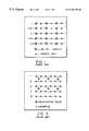
- FIG. 1is a schematic illustration of the positions of the Y,Cb,Cr sample sites on the scan lines of an interlaced picture, as used in the conventional 4:2:2 YCbCr format of the prior art.
- FIG. 2is a schematic illustration of the sample site positions in a frame buffer, as used in the 4:2:2 YCbCr format of FIG. 1 .
- FIG. 3is a schematic illustration of the positions of the Y,Cb,Cr sample sites on the scan lines of a non-interlaced picture, as used in the conventional 4:2:0 YCbCr format of the prior art.
- FIGS. 4A and 4Bare schematic illustrations of the flow chart of a method embodiment of the present invention.
- FIG. 5is a schematic illustration of a digital video camera, a host, and a link between them, according to a preferred embodiment of the present invention.
- FIG. 6is a schematic illustration of the tagging scheme performed in the Y domain on a single active video line of a CIF size video frame, according to a preferred embodiment of the present invention.
- FIG. 7is a schematic illustration showing the Cr averaging scheme performed in the Cr/Cb domain, according to a preferred embodiment of the present invention.
- FIG. 8is a schematic illustration showing the Cb averaging scheme performed in the Cr/Cb domain, according to a preferred embodiment of the present invention.
- YCbCr color systemwas developed as part of Recommendation ITU-R BT.601 during the development of a worldwide digital component video standard.
- Y valuesare defined to have a nominal range of 16 to 235
- Cb and Cr valuesare defined to have a range of 16 to 240, with the 128 level corresponding to zero.
- FIG. 1illustrates the positions of the Y,Cb,Cr sample sites on the scan lines of an interlaced picture, as utilized in the 4:2:2 YCbCr format, often used in consumer video applications.
- each samplehas a Y, a Cb, and a Cr value.
- Each sampletypically has 8 bits per component in consumer applications or 10 bits per component in editing applications. If a frame buffer, which has all three color components for each pixel, is used, each sample in consumer applications therefore requires 16 bits per pixel or 20 bits for editing applications, usually formatted as shown in FIG. 2, where the pixel numbers are given after the dash line.
- the Y samples for which no Cb and Cr data have been savedtypically have to use interpolated Cb and Cr data from the previous and next samples that have the Cb and Cr data.
- FIG. 3represents 4:2:0 coded picture sampling with the positions of the Y,Cb,Cr sample sites on the scan lines of a non-interlaced picture, as used in the 4:2:0 YCbCr format, utilized by the H.261 and H.263 video teleconferencing standards and the MPEG video compression standard.
- the 4:2:0 YCbCr formatimplements a 2:1 reduction of Cb and Cr in both the vertical and horizontal directions.
- the video compression method implemented in the preferred embodiment of the present inventionoperates in the YCbCr 4:2:0 or 4:2:2 format mode and is applied to the 4:2:0 or 4:2:2 data stream, although it may operate in other color systems and format modes, as well. Because much better fidelity in the image can be preserved by not mixing together the color and brightness information, the method preferably operates on digital video cameras which have separate chrominance and luminance signals. Therefore the preferred method of the present invention operates in two separate domains, the Y (luminance) domain and the Cr/Cb (chrominance) domain.
- FIGS. 4A and 4BA flow chart of the preferred method of the present invention is shown in FIGS. 4A and 4B.
- the methodoperates on one video line at the time, and thus does not require lengthy frame buffers for its implementation.
- the methodWhen applied in the Y domain the method operates in real-time and treats each horizontal video line as a separate entity, on a pixel-by-pixel basis. Therefore, in the Y domain there is no inter-frame or interline data correlation, because there is no need to save data before the transfer on a bus, and no line buffer is needed, thus saving space, cost and transfer time.
- the busmay be the Universal Serial Bus (USB) or another serial or parallel bus.
- USBUniversal Serial Bus
- the methodis based on tagging pixels in a video line according to the differences in their luminance (Y) values.
- the value of a threshold for detecting a change in the luminance value between pixelscan be predetermined and is programmable, as shown in step 13 .
- the threshold valuecontrols the image quality; the lower the threshold, the higher the image quality.
- pixels' Y valuesare received one by one and pixels to be tagged are determined in step 17 .
- the Y domain compressionis performed in step 19 .
- an averaging step 21is used to obtain the averaged Cr and Cb values for a transfer video block.
- a line buffer 24shown in FIG. 5, is needed by the averaging step 21 and is used to hold one or, at most, two lines of digitized pixel data.
- the maximum size of a transfer field, containing pixel informationis limited in the step 13 to a finite and programmable value.
- the preferred method of the present inventionis implemented within a digital video camera 10 , attached to a host computer 28 via a bus 30 , as shown in FIG. 5 .
- the host computer 28is preferably a personal computer, capable of handling fast calculations and storing large amounts of data.
- the digital electronic camera 10has an image sensor array 12 , which may be covered with a color filter mosaic called a color filter array (CFA) 14 .
- CFAcolor filter array
- the method of the present inventionmay also be applied to monochrome cameras, in which case there is no Cr and Cb data.
- the digital video camera 10contains its own Pixel Processing Controller (PPC) 26 , which is preferably an Application Specific Integrated Circuit (ASIC) chip, which has a Y domain compression module 20 for tagging the pixel locations, and a Cr/Cb domain compression module 22 for averaging the Cr and Cb values.
- PPCPixel Processing Controller
- the PPC 26may also be used, if needed, to transform the image data from the camera's color system (such as RGB) to another color system, such as YCbCr, in which the luminance and the chrominance values are separated, and to perform compression in the 4:2:2 or 4:2:0 format.
- the PPC chip 26has a limited-size on-board data storage area 29 to store a limited number of data values and parameters needed for the video compression.
- the size of the on-board data storage area 29is directly related to a predetermined value chosen in the step 13 for the maximum number of pixels allowed between the tagged pixels, which has to be kept small to obtain good resolution, and is preferably only 8 to 16 pixels.
- the datais transferred to the host computer 28 which has a bus controller 34 , a microprocessor 38 , and a data storage area 36 .
- the host computer 28has to perform data decompression and data transformation from the YCbCr domain into the RGB domain before displaying the video frames on a display 40 .
- FIG. 6illustrates how the Y domain tagging is performed on a single active video line of a CIF-size video frame, according to the preferred method of the present invention.
- the active pixels on the lineare indicated as incoming pixels 1 through 352 , represented with the symbol Y i .
- Y trepresents the Y value for the previously tagged pixel.
- L trepresents the length associated with the tagged pixel Y t .
- the variable L thas the value obtained with a counter of the step 15 and represents the number of pixels since the last tagged pixel.
- Y threpresents the threshold value used for tagging, preferably saved with the Y t , and L t values in the camera data storage area 29 .
- the Y compression algorithmcalculates the absolute value of the difference between an incoming pixel's Y i value and the Y t value of the previously tagged pixel in step 17 . If the absolute value of the difference exceeds the threshold Y th , preferably set by the host microprocessor 38 , the Y i value for this incoming pixel and the number of pixels since the last tagged pixel (length L t ) are saved in the data storage area 29 of the camera PPC chip 26 . This pixel becomes the new tagged pixel and the process is repeated for new pixels until the end of the current video line is reached.
- the tagged pixel luminance and length valuesare transmitted to the host computer 28 in step 50 where they are used in a decompression and interpolation software program 60 stored in the host data storage area 36 , to reconstruct the video, through replication and/or interpolation of the values between the tagged pixels on the video line. The process is repeated for the next video line.
- the host computer 28receives the compressed video stream from the camera 10 and uses two algorithms in the interpolation software program 60 for decompressing and regenerating the original 4:2:0 or 4:2:2 image. These algorithms are applied to the Y domain and the Cr/Cb domain separately. Decompression in the Cr/Cb domain is a method opposite of the averaging method described below. In the Y domain, the decompression includes interpolation between the tagged pixels, which may be accomplished by copying a single pixel a number of times, based on the length value in the Y domain.
- FIG. 6illustrates a single active video line where blank circles represent incoming pixels Y i 63 , chosen from a group of pixels Y 1 -Y 352 , and shaded circles represent tagged pixels Y t1 , Y t2 , 65 .
- L t1 , and L t2represent values of the length 67 associated with each tagged pixel 65 .
- the tagged pixel Y t1has the length L t1 of four because it has four pixels associated with it, while Y t2 has the length L t2 of three.
- the goal of the video compression method of the present inventionis to minimize the number of tagged pixels transmitted to the host as well as to shorten the transfer field size. Therefore, if the length for each tagged pixel is kept beyond 16 pixels it can be represented with a field of 4 bits.
- the length representing the number of pixels in a run associated with a tagged pixelmay be encoded in the camera 10 , after the step 19 , and decoded in the host computer 28 .
- the actual implementation of the Y domain compression method of the present inventionmay require use of special limitations, such as regarding the beginning and end of the video line.
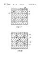
- FIGS. 7 and 8show the averaging scheme for the Cr/Cb domain, used in an averaging step 21 , and performed in the Cr/Cb compression module 22 of the digital camera PPC 26 .
- a single Cr valueis calculated as the average value for preferably four Cr values in the 4:2:0 format, and for eight Cr values in the 4:2:2 format.
- a single Cb valueis calculated to represent all Cb values in a group of pixels.
- the 4:2:2 to 4:2:0 format compressionhas to be performed in a method step 11 of FIG. 4A on the Cr and Cb data. Y values do not change between the 4:2:2 and 4:2:0 formats.
- the algorithm of the step 21performs averaging within each region of the Cr/Cb domain, and obtains a single Cr and a single Cb value for each region.
- this ratiois preferably 4:1, because four Cr values are averaged into a single Cr value, and in the Cb domain the ratio is preferably 16:1, because sixteen Cb values are averaged into a single Cb value.
- this ratiois preferably 8:1, because eight Cr values are averaged into a single Cr value, and in the Cb domain the ratio is preferably 32:1, because thirty-two Cb values are averaged into a single Cb value. Therefore, the Cr/Cb domain averaging algorithm of step 21 needs the short line buffer 24 to save data for this compression scheme.
- FIG. 7illustrates the Cr domain, 4:2:0 format, 4:1 averaging of the present invention, wherein each blank circle represents a Y value 81 , a circle with an “ ⁇ ” symbol represents a Cr value 83 , each dark circle represents a Cb value 85 , and each circle with a symbol “ ⁇ ” represents an average Cr value 87 .
- four adjacent Cr valuesare used to generated a single averaged Cr value 87 , as shown in FIG. 7 .
- This calculated average Cr value 87is sent to the host computer 28 in the step 50 and is used to reconstruct the Cr values for this region of the video line. The rest of the Cr values for the video frame is calculated in the same manner.
- Four adjacent Cb valuesare used to generated a single intermediate averaged Cb value 97 , as shown in FIG. 8 .
- This intermediate value 97is averaged with three other values calculated similarly and the result is sent to the host computer 28 and used to reconstruct the Cb values for this region of the video line.
- the rest of the Cb values for the video frameare calculated in the same manner.
- the data obtained with the preferred method of the present inventionmay be further compressed by concatenating and/or encoding the information.
- the two 4-bit length codes for two pixelsmay be concatenated into a single byte.
- a similar methodmay be used in the Cr/Cb domain, because the number of Cr and Cb values for every frame is constant and known, and there are 88 Cr values in each of 72 Cr lines per frame, and there are 44 Cb values in each of 36 Cb lines per frame.
- the compressed Cr/Cb format for a full video framemay have the alternative Cr-only and Cr/Cb lines, where each Cr-only line has only Cr values, and is followed by the Cr/Cb line of alternating Cr and Cb values.
- the principles of the present inventionhave been proven by experimentation, using the preferred embodiments of the present invention and compared with the conventional video compression methods. The obtained results have proven the feasibility and superiority of the present invention.
- the method of the inventionwas applied to a digital video camera with the USB bus working in an isochronous traffic mode.
- the USB busis an isochronous bus which has two isochronous pipes with guaranteed, regularly scheduled, transfer of digital data.
- the bus pipesmay be used to separately transmit compressed or uncompressed Y and Cr/Cb data, one domain per each pipe.
- the preferred method of the present inventionhas been applied to the USB-based digital video camera.
- the USB-based digital video cameratypically contains an external buffer memory and may support three different modes: with no external buffer memory, with an external buffer memory of 32 Kbytes, and with an external buffer memory of 128 Kbytes. It has been confirmed that the video compression algorithm of the present invention allows the camera to transfer a higher number of frames to the host than do conventional methods, depending on the compression ratio and the USB bandwidth available. Furthermore, the data transfer of CIF-size frames between the camera and the host has been performed with the higher rate even without using an external frame buffer, or when only a smaller, 32K byte frame buffer is used.
- the preferred method of the present inventionis able to perform fast compression and decompression and enable real time transmission with a low average compression ratio of about 3:1 for moderately complex color images, as required for the USB bus, while preserving a high degree of image sharpness.
- CIF-size video frameshaving 352 pixels per line and 288 lines per frame, can be transmitted to the host at the average rate of between 20 and 30 frames per second, with good resolution.
- the actual achieved compression ratiodepends on the amount of detail and motion in the particular video frame sequence.
- An additional benefit of the present inventionincludes the feature that allows the change of the compression ratio with the threshold value Y th .
- much higher compression ratios, such as 10:1may be obtained when needed to squeeze image sequences through relatively low bandwidth transmission channels, such as for consumer delivery of moving images or when applied to applications that do not require very high quality, such as in video conferencing.
- a frame rate control algorithmis implemented, which works in conjunction with the compression algorithm and allows the user to request a specific frame rate.
- the host computer 28with the knowledge of the available bus bandwidth and the size of the host data storage area 36 , calculates the required number of bytes per frame to achieve the selected frame rate.
- the host computer 28then calculates and sets the value of the maximum length size, as well as the Y th value, and sends these parameters to the camera 10 .
- the preferred embodiments of the present inventionare capable of producing digital imaging devices with a low gate count and power requirements, thus small, inexpensive, and yet capable of transferring 30 video frames per second.
- USB-based digital video cameraAlthough illustrated on a USB-based digital video camera, are believed to be applicable to other types of still and video cameras which use silicone chips, such as CIF cameras using a CCD detector. It is understood that the principles of this invention are particularly applicable to low cost digital imaging devices which have to perform on-the-fly video compression and transmit samples on a bus with the limited data bandwidth, which must perform data interpolation before the image is further processed and displayed.
- Such devicesmay be office automation digital linear sensors, digital fingerprint detectors, digital scanners, digital broadcast television, compact disk video, multimedia, video conferencing systems, desktop face-to-face visual communications (videophone), dynamic medical imaging devices, high definition TV, video cassette recorders, copy machines, and fax machines.
Landscapes
- Engineering & Computer Science (AREA)
- Multimedia (AREA)
- Signal Processing (AREA)
- Theoretical Computer Science (AREA)
- Compression Or Coding Systems Of Tv Signals (AREA)
- Studio Devices (AREA)
- Compression Of Band Width Or Redundancy In Fax (AREA)
Abstract
Description
Claims (5)
Priority Applications (4)
| Application Number | Priority Date | Filing Date | Title |
|---|---|---|---|
| US09/042,124US6256350B1 (en) | 1998-03-13 | 1998-03-13 | Method and apparatus for low cost line-based video compression of digital video stream data |
| PCT/US1999/003363WO1999046936A1 (en) | 1998-03-13 | 1999-02-17 | Method and apparatus for low cost line-based video compression of digital video stream data |
| AU27684/99AAU2768499A (en) | 1998-03-13 | 1999-02-17 | Method and apparatus for low cost line-based video compression of digital video stream data |
| TW088103495ATW416249B (en) | 1998-03-13 | 1999-03-08 | Method and apparatus for low cost line-based video compression of digital video stream data |
Applications Claiming Priority (1)
| Application Number | Priority Date | Filing Date | Title |
|---|---|---|---|
| US09/042,124US6256350B1 (en) | 1998-03-13 | 1998-03-13 | Method and apparatus for low cost line-based video compression of digital video stream data |
Publications (1)
| Publication Number | Publication Date |
|---|---|
| US6256350B1true US6256350B1 (en) | 2001-07-03 |
Family
ID=21920179
Family Applications (1)
| Application Number | Title | Priority Date | Filing Date |
|---|---|---|---|
| US09/042,124Expired - Fee RelatedUS6256350B1 (en) | 1998-03-13 | 1998-03-13 | Method and apparatus for low cost line-based video compression of digital video stream data |
Country Status (4)
| Country | Link |
|---|---|
| US (1) | US6256350B1 (en) |
| AU (1) | AU2768499A (en) |
| TW (1) | TW416249B (en) |
| WO (1) | WO1999046936A1 (en) |
Cited By (22)
| Publication number | Priority date | Publication date | Assignee | Title |
|---|---|---|---|---|
| US20020009293A1 (en)* | 2000-02-03 | 2002-01-24 | Aldrich Kipp A. | HDTV video server |
| US20020122194A1 (en)* | 2001-02-09 | 2002-09-05 | Naoki Kuwata | Image processing system via network |
| US6486889B1 (en)* | 1999-12-17 | 2002-11-26 | Xerox Corporation | Methods and apparatus for transforming RGB video |
| US6540733B2 (en)* | 2000-12-29 | 2003-04-01 | Corazon Technologies, Inc. | Proton generating catheters and methods for their use in enhancing fluid flow through a vascular site occupied by a calcified vascular occlusion |
| US6704310B1 (en)* | 1999-06-30 | 2004-03-09 | Logitech Europe, S.A. | Header encoding method and apparatus for packet-based bus |
| US6747661B1 (en)* | 2000-02-18 | 2004-06-08 | Micron Technology, Inc. | Graphics data compression method and system |
| US20040184529A1 (en)* | 2003-02-14 | 2004-09-23 | Canon Europa N.V. | Method and device for analyzing video sequences in a communication network |
| US20050008077A1 (en)* | 2003-03-31 | 2005-01-13 | Sultan Weatherspoon | Video compression method and apparatus |
| US6882361B1 (en)* | 2000-04-19 | 2005-04-19 | Pixelworks, Inc. | Imager linked with image processing station |
| US20050169366A1 (en)* | 2004-02-02 | 2005-08-04 | Clark Adam L. | System and method for compressing and encoding video |
| US20050169365A1 (en)* | 2004-02-02 | 2005-08-04 | Clark Adam L. | Data encoding using multi-dimensional redundancies |
| US7069342B1 (en)* | 2001-03-01 | 2006-06-27 | Cisco Technology, Inc. | Communication system with content-based data compression |
| US20060140270A1 (en)* | 2002-09-05 | 2006-06-29 | Zhengguo Li | Method and an apparatus for controlling the rate of a video sequence; a video encoding device |
| US20060153291A1 (en)* | 2005-01-10 | 2006-07-13 | Christison Gregory L | Digital video line-by-line dynamic rate adaptation |
| US7095435B1 (en)* | 2004-07-21 | 2006-08-22 | Hartman Richard L | Programmable multifunction electronic camera |
| US20060188151A1 (en)* | 2005-02-23 | 2006-08-24 | Lexmark International, Inc. | Method for processing data for use with a video display of an imaging apparatus |
| US20080012953A1 (en)* | 2006-07-13 | 2008-01-17 | Vimicro Corporation | Image Sensors |
| US20080137737A1 (en)* | 2006-12-07 | 2008-06-12 | Wiquest Communications, Inc. | Line-Based Video Rate Control |
| US20080187184A1 (en)* | 2007-02-01 | 2008-08-07 | Kabushiki Kaisha Toshiba | System and method for facial image enhancement |
| WO2007053286A3 (en)* | 2005-10-12 | 2009-05-14 | First Data Corp | Video conferencing systems and methods |
| US20110187897A1 (en)* | 2002-05-07 | 2011-08-04 | Yasumasa Nakajima | Update Control of Image Processing Control Data |
| US20130084003A1 (en)* | 2011-09-30 | 2013-04-04 | Richard E. Crandall | Psychovisual Image Compression |
Citations (7)
| Publication number | Priority date | Publication date | Assignee | Title |
|---|---|---|---|---|
| US4541012A (en)* | 1982-01-04 | 1985-09-10 | Compression Labs, Inc. | Video bandwidth reduction system employing interframe block differencing and transform domain coding |
| US4764805A (en)* | 1987-06-02 | 1988-08-16 | Eastman Kodak Company | Image transmission system with line averaging preview mode using two-pass block-edge interpolation |
| WO1993007719A1 (en) | 1991-10-02 | 1993-04-15 | Tandy Corporation | Method and apparatus for encoding full color video data and protocol for encoding same |
| US5341318A (en)* | 1990-03-14 | 1994-08-23 | C-Cube Microsystems, Inc. | System for compression and decompression of video data using discrete cosine transform and coding techniques |
| US5537231A (en)* | 1991-08-30 | 1996-07-16 | Canon Kabushiki Kaisha | Image transmission apparatus |
| US5543939A (en)* | 1989-12-28 | 1996-08-06 | Massachusetts Institute Of Technology | Video telephone systems |
| WO1998010587A1 (en) | 1996-09-04 | 1998-03-12 | Winbond Systems Laboratory, Inc. | Moving picture camera with universal serial bus interface |
- 1998
- 1998-03-13USUS09/042,124patent/US6256350B1/ennot_activeExpired - Fee Related
- 1999
- 1999-02-17WOPCT/US1999/003363patent/WO1999046936A1/enactiveApplication Filing
- 1999-02-17AUAU27684/99Apatent/AU2768499A/ennot_activeAbandoned
- 1999-03-08TWTW088103495Apatent/TW416249B/enactive
Patent Citations (7)
| Publication number | Priority date | Publication date | Assignee | Title |
|---|---|---|---|---|
| US4541012A (en)* | 1982-01-04 | 1985-09-10 | Compression Labs, Inc. | Video bandwidth reduction system employing interframe block differencing and transform domain coding |
| US4764805A (en)* | 1987-06-02 | 1988-08-16 | Eastman Kodak Company | Image transmission system with line averaging preview mode using two-pass block-edge interpolation |
| US5543939A (en)* | 1989-12-28 | 1996-08-06 | Massachusetts Institute Of Technology | Video telephone systems |
| US5341318A (en)* | 1990-03-14 | 1994-08-23 | C-Cube Microsystems, Inc. | System for compression and decompression of video data using discrete cosine transform and coding techniques |
| US5537231A (en)* | 1991-08-30 | 1996-07-16 | Canon Kabushiki Kaisha | Image transmission apparatus |
| WO1993007719A1 (en) | 1991-10-02 | 1993-04-15 | Tandy Corporation | Method and apparatus for encoding full color video data and protocol for encoding same |
| WO1998010587A1 (en) | 1996-09-04 | 1998-03-12 | Winbond Systems Laboratory, Inc. | Moving picture camera with universal serial bus interface |
Non-Patent Citations (2)
| Title |
|---|
| "Image Processing Circuit, IBM Technical Disclosure Bulletin," vol. 37, No. 2A, Feb. 1, 1994, p. 439/440 XP000433393. |
| "Method of Run Length Coding for Natural Images," IBM Technical Disclosure Bulletin, vol. 31, No. 5, Oct. 1, 1988, pp. 4-6, XP000024776. |
Cited By (37)
| Publication number | Priority date | Publication date | Assignee | Title |
|---|---|---|---|---|
| US6704310B1 (en)* | 1999-06-30 | 2004-03-09 | Logitech Europe, S.A. | Header encoding method and apparatus for packet-based bus |
| US6486889B1 (en)* | 1999-12-17 | 2002-11-26 | Xerox Corporation | Methods and apparatus for transforming RGB video |
| US20020009293A1 (en)* | 2000-02-03 | 2002-01-24 | Aldrich Kipp A. | HDTV video server |
| US6747661B1 (en)* | 2000-02-18 | 2004-06-08 | Micron Technology, Inc. | Graphics data compression method and system |
| US6882361B1 (en)* | 2000-04-19 | 2005-04-19 | Pixelworks, Inc. | Imager linked with image processing station |
| US6540733B2 (en)* | 2000-12-29 | 2003-04-01 | Corazon Technologies, Inc. | Proton generating catheters and methods for their use in enhancing fluid flow through a vascular site occupied by a calcified vascular occlusion |
| US7327490B2 (en)* | 2001-02-09 | 2008-02-05 | Seiko Epson Corporation | Image processing system via network |
| US20020122194A1 (en)* | 2001-02-09 | 2002-09-05 | Naoki Kuwata | Image processing system via network |
| US7069342B1 (en)* | 2001-03-01 | 2006-06-27 | Cisco Technology, Inc. | Communication system with content-based data compression |
| US8559044B2 (en) | 2002-05-07 | 2013-10-15 | Seiko Epson Corporation | Update control of image processing control data |
| US8279481B2 (en) | 2002-05-07 | 2012-10-02 | Seiko Epson Corporation | Update control of image processing control data |
| US20110187897A1 (en)* | 2002-05-07 | 2011-08-04 | Yasumasa Nakajima | Update Control of Image Processing Control Data |
| US7876821B2 (en)* | 2002-09-05 | 2011-01-25 | Agency For Science, Technology And Research | Method and an apparatus for controlling the rate of a video sequence; a video encoding device |
| US20060140270A1 (en)* | 2002-09-05 | 2006-06-29 | Zhengguo Li | Method and an apparatus for controlling the rate of a video sequence; a video encoding device |
| US20040184529A1 (en)* | 2003-02-14 | 2004-09-23 | Canon Europa N.V. | Method and device for analyzing video sequences in a communication network |
| US7466865B2 (en)* | 2003-02-14 | 2008-12-16 | Canon Europa, N.V. | Method and device for analyzing video sequences in a communication network |
| US20090232201A1 (en)* | 2003-03-31 | 2009-09-17 | Duma Video, Inc. | Video compression method and apparatus |
| US7519115B2 (en) | 2003-03-31 | 2009-04-14 | Duma Video, Inc. | Video compression method and apparatus |
| US20050008077A1 (en)* | 2003-03-31 | 2005-01-13 | Sultan Weatherspoon | Video compression method and apparatus |
| US20090196353A1 (en)* | 2003-03-31 | 2009-08-06 | Duma Video, Inc. | Video compression method and apparatus |
| US20050169366A1 (en)* | 2004-02-02 | 2005-08-04 | Clark Adam L. | System and method for compressing and encoding video |
| US20050169365A1 (en)* | 2004-02-02 | 2005-08-04 | Clark Adam L. | Data encoding using multi-dimensional redundancies |
| US7010033B2 (en) | 2004-02-02 | 2006-03-07 | Adams Platform Pty Ltd. | System and method for compressing and encoding video |
| US7095435B1 (en)* | 2004-07-21 | 2006-08-22 | Hartman Richard L | Programmable multifunction electronic camera |
| US20060153291A1 (en)* | 2005-01-10 | 2006-07-13 | Christison Gregory L | Digital video line-by-line dynamic rate adaptation |
| US8355434B2 (en)* | 2005-01-10 | 2013-01-15 | Qualcomm Incorporated | Digital video line-by-line dynamic rate adaptation |
| US20060188151A1 (en)* | 2005-02-23 | 2006-08-24 | Lexmark International, Inc. | Method for processing data for use with a video display of an imaging apparatus |
| WO2007053286A3 (en)* | 2005-10-12 | 2009-05-14 | First Data Corp | Video conferencing systems and methods |
| US20080012953A1 (en)* | 2006-07-13 | 2008-01-17 | Vimicro Corporation | Image Sensors |
| US20080137738A1 (en)* | 2006-12-07 | 2008-06-12 | Wiquest Communications, Inc. | Line-based video compression |
| US8165203B2 (en)* | 2006-12-07 | 2012-04-24 | Qualcomm Incorporated | Line-based video rate control |
| US8208554B2 (en)* | 2006-12-07 | 2012-06-26 | Qualcomm Incorporated | Line-based video compression |
| US20080137737A1 (en)* | 2006-12-07 | 2008-06-12 | Wiquest Communications, Inc. | Line-Based Video Rate Control |
| JP2008192138A (en)* | 2007-02-01 | 2008-08-21 | Toshiba Corp | System and method for modifying the facial region of an image |
| US20080187184A1 (en)* | 2007-02-01 | 2008-08-07 | Kabushiki Kaisha Toshiba | System and method for facial image enhancement |
| US20130084003A1 (en)* | 2011-09-30 | 2013-04-04 | Richard E. Crandall | Psychovisual Image Compression |
| US8891894B2 (en)* | 2011-09-30 | 2014-11-18 | Apple Inc. | Psychovisual image compression |
Also Published As
| Publication number | Publication date |
|---|---|
| TW416249B (en) | 2000-12-21 |
| AU2768499A (en) | 1999-09-27 |
| WO1999046936A1 (en) | 1999-09-16 |
Similar Documents
| Publication | Publication Date | Title |
|---|---|---|
| US6256350B1 (en) | Method and apparatus for low cost line-based video compression of digital video stream data | |
| US6184936B1 (en) | Multi-function USB capture chip using bufferless data compression | |
| US5412427A (en) | Electronic camera utilizing image compression feedback for improved color processing | |
| US8564683B2 (en) | Digital camera device providing improved methodology for rapidly taking successive pictures | |
| US6151075A (en) | Device and method for converting frame rate | |
| US7688384B2 (en) | Personal multimedia device video format conversion across multiple video formats | |
| US6825876B1 (en) | Digital camera device with methodology for efficient color conversion | |
| US5790717A (en) | Apparatus and method for predicting subjective quality of compressed images | |
| US6023295A (en) | ADPCM recompression and decompression of a data stream of a video image and differential variance estimator | |
| US6005638A (en) | Frame averaging for use in processing video data | |
| US6665343B1 (en) | Methods and arrangements for a converting a high definition image to a lower definition image using wavelet transforms | |
| US6266093B1 (en) | Color video camera method and system | |
| US6108027A (en) | Progressive still frame mode | |
| US6847333B2 (en) | Method of and system for low-bandwidth transmission of color video | |
| US5684544A (en) | Apparatus and method for upsampling chroma pixels | |
| JPH07162848A (en) | Processor for digital image signal | |
| JP2000504911A (en) | Facsimile compliant image compression method and system | |
| US5751861A (en) | Reducing residual artifacts in video coding schemes with integer motion compensation | |
| US20020149696A1 (en) | Method for presenting improved motion image sequences | |
| EP1727352A1 (en) | Image compression method, image compression device, image transmission system, data compression pre-processing device, and computer program | |
| US7724305B2 (en) | Video data conversion method and system for multiple receivers | |
| US20060008154A1 (en) | Video compression and decompression to virtually quadruple image resolution | |
| US6628708B1 (en) | Method and system for compressing color video data within a data processing system | |
| JP2919236B2 (en) | Image coding device | |
| US6208754B1 (en) | Image compression and expansion device using pixel offset |
Legal Events
| Date | Code | Title | Description |
|---|---|---|---|
| AS | Assignment | Owner name:ROCKWELL SEMICONDUCTOR SYSTEMS, INC., CALIFORNIA Free format text:ASSIGNMENT OF ASSIGNORS INTEREST;ASSIGNORS:KATIBIAN, BEHNAM S.;BISHAY, MAGUED M.;REEL/FRAME:009073/0538 Effective date:19980312 | |
| AS | Assignment | Owner name:CREDIT SUISSE FIRST BOSTON, NEW YORK Free format text:SECURITY INTEREST;ASSIGNORS:CONEXANT SYSTEMS, INC.;BROOKTREE CORPORATION;BROOKTREE WORLDWIDE SALES CORPORATION;AND OTHERS;REEL/FRAME:009826/0056 Effective date:19981221 | |
| AS | Assignment | Owner name:CONEXANT SYSTEMS, INC., CALIFORNIA Free format text:CHANGE OF NAME;ASSIGNOR:ROCKWELL SEMICONDUCTOR SYSTEMS, INC.;REEL/FRAME:009730/0350 Effective date:19981014 | |
| AS | Assignment | Owner name:CONEXANT SYSTEMS, INC., CALIFORNIA Free format text:RELEASE BY SECURED PARTY;ASSIGNOR:CREDIT SUISSE FIRST BOSTON;REEL/FRAME:012273/0217 Effective date:20011018 Owner name:BROOKTREE WORLDWIDE SALES CORPORATION, CALIFORNIA Free format text:RELEASE BY SECURED PARTY;ASSIGNOR:CREDIT SUISSE FIRST BOSTON;REEL/FRAME:012273/0217 Effective date:20011018 Owner name:BROOKTREE CORPORATION, CALIFORNIA Free format text:RELEASE BY SECURED PARTY;ASSIGNOR:CREDIT SUISSE FIRST BOSTON;REEL/FRAME:012273/0217 Effective date:20011018 Owner name:CONEXANT SYSTEMS WORLDWIDE, INC., CALIFORNIA Free format text:RELEASE BY SECURED PARTY;ASSIGNOR:CREDIT SUISSE FIRST BOSTON;REEL/FRAME:012273/0217 Effective date:20011018 | |
| AS | Assignment | Owner name:PICTOS TECHNOLOGIES, INC., CALIFORNIA Free format text:ASSIGNMENT OF ASSIGNORS INTEREST;ASSIGNOR:CONEXENT SYSTEMS, INC.;REEL/FRAME:013496/0589 Effective date:20020701 | |
| AS | Assignment | Owner name:ESS TECHNOLOGIES INTERNATIONAL, INC., CALIFORNIA Free format text:ASSIGNMENT OF ASSIGNORS INTEREST;ASSIGNOR:PICTOS TECHNOLOGIES, INC.;REEL/FRAME:015494/0513 Effective date:20040625 | |
| REMI | Maintenance fee reminder mailed | ||
| REMI | Maintenance fee reminder mailed | ||
| FPAY | Fee payment | Year of fee payment:4 | |
| SULP | Surcharge for late payment | ||
| FEPP | Fee payment procedure | Free format text:PAYOR NUMBER ASSIGNED (ORIGINAL EVENT CODE: ASPN); ENTITY STATUS OF PATENT OWNER: LARGE ENTITY Free format text:PAYER NUMBER DE-ASSIGNED (ORIGINAL EVENT CODE: RMPN); ENTITY STATUS OF PATENT OWNER: LARGE ENTITY | |
| FEPP | Fee payment procedure | Free format text:PAYOR NUMBER ASSIGNED (ORIGINAL EVENT CODE: ASPN); ENTITY STATUS OF PATENT OWNER: LARGE ENTITY Free format text:PAYER NUMBER DE-ASSIGNED (ORIGINAL EVENT CODE: RMPN); ENTITY STATUS OF PATENT OWNER: LARGE ENTITY | |
| AS | Assignment | Owner name:THE PRIVATE BANK OF THE PENINSULA, CALIFORNIA Free format text:SECURITY AGREEMENT;ASSIGNOR:ESS TECHNOLOGY, INC.;REEL/FRAME:021212/0413 Effective date:20080703 Owner name:THE PRIVATE BANK OF THE PENINSULA,CALIFORNIA Free format text:SECURITY AGREEMENT;ASSIGNOR:ESS TECHNOLOGY, INC.;REEL/FRAME:021212/0413 Effective date:20080703 | |
| REMI | Maintenance fee reminder mailed | ||
| LAPS | Lapse for failure to pay maintenance fees | ||
| STCH | Information on status: patent discontinuation | Free format text:PATENT EXPIRED DUE TO NONPAYMENT OF MAINTENANCE FEES UNDER 37 CFR 1.362 | |
| FP | Lapsed due to failure to pay maintenance fee | Effective date:20090703 | |
| AS | Assignment | Owner name:IMPERIUM (IP) HOLDINGS, INC., NEW YORK Free format text:ASSIGNMENT OF ASSIGNORS INTEREST;ASSIGNOR:ESS TECHNOLOGY, INC.;REEL/FRAME:026738/0136 Effective date:20110629 Owner name:ESS TECHNOLOGY, INC., CALIFORNIA Free format text:ASSIGNMENT OF ASSIGNORS INTEREST;ASSIGNOR:ESS TECHNOLOGY INTERNATIONAL, INC.;REEL/FRAME:026737/0929 Effective date:20110628 | |
| AS | Assignment | Owner name:PICTOS TECHNOLOGIES INC., CALIFORNIA Free format text:CHANGE OF NAME;ASSIGNOR:IMPERIUM IP HOLDINGS (CAYMAN), LTD.;REEL/FRAME:056595/0208 Effective date:20180430 |