US6256303B1 - Wireless broadcast link to remote receiver - Google Patents
Wireless broadcast link to remote receiverDownload PDFInfo
- Publication number
- US6256303B1 US6256303B1US09/419,178US41917899AUS6256303B1US 6256303 B1US6256303 B1US 6256303B1US 41917899 AUS41917899 AUS 41917899AUS 6256303 B1US6256303 B1US 6256303B1
- Authority
- US
- United States
- Prior art keywords
- signal
- transmitter
- frequency
- receiver
- modulated signal
- Prior art date
- Legal status (The legal status is an assumption and is not a legal conclusion. Google has not performed a legal analysis and makes no representation as to the accuracy of the status listed.)
- Expired - Lifetime
Links
- 230000008054signal transmissionEffects0.000claimsabstractdescription45
- 238000006243chemical reactionMethods0.000claimsabstractdescription6
- 230000005236sound signalEffects0.000claimsdescription27
- 230000005540biological transmissionEffects0.000claimsdescription25
- 239000013078crystalSubstances0.000claimsdescription7
- 230000004044responseEffects0.000claimsdescription3
- 238000010586diagramMethods0.000description7
- 239000004020conductorSubstances0.000description4
- 230000002238attenuated effectEffects0.000description3
- 239000000919ceramicSubstances0.000description3
- 239000002131composite materialSubstances0.000description3
- 230000001105regulatory effectEffects0.000description3
- 230000001276controlling effectEffects0.000description2
- 230000005404monopoleEffects0.000description2
- 230000000007visual effectEffects0.000description2
- 230000004913activationEffects0.000description1
- 230000004075alterationEffects0.000description1
- 230000008859changeEffects0.000description1
- 238000010276constructionMethods0.000description1
- 238000012937correctionMethods0.000description1
- 230000003247decreasing effectEffects0.000description1
- 238000001514detection methodMethods0.000description1
- 229910003460diamondInorganic materials0.000description1
- 239000010432diamondSubstances0.000description1
- 230000000694effectsEffects0.000description1
- 230000006870functionEffects0.000description1
- 238000005286illuminationMethods0.000description1
- 230000000670limiting effectEffects0.000description1
- 230000010363phase shiftEffects0.000description1
- 238000000926separation methodMethods0.000description1
- 230000001755vocal effectEffects0.000description1
Images


Classifications
- H—ELECTRICITY
- H04—ELECTRIC COMMUNICATION TECHNIQUE
- H04B—TRANSMISSION
- H04B1/00—Details of transmission systems, not covered by a single one of groups H04B3/00 - H04B13/00; Details of transmission systems not characterised by the medium used for transmission
- H04B1/06—Receivers
- H04B1/16—Circuits
- H—ELECTRICITY
- H04—ELECTRIC COMMUNICATION TECHNIQUE
- H04N—PICTORIAL COMMUNICATION, e.g. TELEVISION
- H04N5/00—Details of television systems
- H04N5/38—Transmitter circuitry for the transmission of television signals according to analogue transmission standards
- H—ELECTRICITY
- H04—ELECTRIC COMMUNICATION TECHNIQUE
- H04B—TRANSMISSION
- H04B1/00—Details of transmission systems, not covered by a single one of groups H04B3/00 - H04B13/00; Details of transmission systems not characterised by the medium used for transmission
- H04B1/38—Transceivers, i.e. devices in which transmitter and receiver form a structural unit and in which at least one part is used for functions of transmitting and receiving
- H04B1/3805—Transceivers, i.e. devices in which transmitter and receiver form a structural unit and in which at least one part is used for functions of transmitting and receiving with built-in auxiliary receivers
Definitions
- the present inventionrelates, in general, to wireless signal transmission systems and apparatus and, specifically, to wireless transmission system capable of transmitting audio or video signals in either analog or digital format via high frequency carrier signals in the 900 MHZ range and, even more specifically, to wireless signal transmission systems wherein a transmitter coupled to a signal source is linked via a wireless connection to a remote receiver and output device.
- Local wireless television transmission systemswhich transmit television or radio signals from a local source, such as a television, VCR, radio set or radio stereo receiver, frequently transmit such signals within a frequency band above 900 MHZ and, preferably, within a frequency band of 902 MHZ to 928 MHZ.
- This frequency bandis desirable because at higher carrier frequencies, the bandwidth of the transmitted signal occupies a smaller region of the transmission bandwidth than at lower carrier frequencies. This leaves more channels available for use and results in decreased RF interference and noise as well as greater flexibility in channel selection.
- stereo audio signalsare transmitted by adding the right and left audio channels to form a first signal and subtracting the right and left channels to form a second signal which is modulated on a subcarrier of 38 KHz.
- the subcarrieris suppressed and the combination of the first signal, the subcarrier modulated second signal, and a 19 KHz pilot signal form a multiplexed stereo signal which modulates a carrier for transmission to a remote receiver.
- Conventional integrated circuits for producing such multiplexed stereo signalsknown as stereo encoder circuits, are available commercially.
- Such high frequency wireless transmission systemsconventionally include a transmitter which is capable of transmitting a television or radio mono or stereo signals and a remote receiver, both having appropriate antennas for transmitting and receiving the source signals as a modulated high frequency carrier.
- the remote receiverhas been mounted in close proximity to or formed as a part of a signal output device, such as an AM/FM stereo receiver, television, for example.
- the distance or separation between the remote receiver antenna and the output deviceis relatively limited due to the low power level signals transmitted at the high carrier frequency. This small transmission range limits the use of additional speakers or an additional receiver and speakers which may not be located in the same general area as the first transmitter and the output device.
- Audio and video signalsare now available through the Internet typically in the form of streaming broadcast of radio or television programs, recorded music, etc.
- the audio and/or video signalsare downloaded from the Internet signal source by a user's Internet service provider and input through a modem to the user's computer.
- the computergenerates signals to an audio and/or video output card which then transmits analog output signals to speakers coupled to the computer or to a monitor for broadcast of the signals.
- the audio system or the monitor employed with a computeris not as sophisticated as the user's home stereo system or television. Further, a user's computer may not be located in the same room or area of a home as the multi-component stereo system or television.
- a wireless signal transmission apparatuswhich is capable of retransmitting high frequency audio and/or video signals modulated on a high frequency carrier by a first transmitter and transmitted wirelessly via the high frequency carrier to a remote receiver for re-broadcast. It would also be desirable to provide a wireless signal transmission apparatus which has an expanded transmission range as compared to previously devised high frequency transmission systems. It would also be desirable to provide a wireless high frequency signal transmission system which is capable of re-broadcasting streaming broadcast signals from the Internet or any other audio and/or video source to a remote receiver which may located at a considerable distance from the originating transmission source.
- the present inventionis a signal transmission apparatus capable of transmitting audio and/or video signals from a suitable signal source via a high frequency (900 MHZ) carrier to a remote receiver which down converts the high frequency carrier signal to a lower frequency carrier signal and combines it with the modulated signal before transmitting the second modulated signal to a further remote receiver capable of demodulating and generating audio and/or video output.
- a high frequency carrier900 MHZ
- the apparatusincludes a first transmitter adapted to be coupled to the signal source for providing audio and/or video frequency signals in either analog or digital format.
- the signal sourcemay be any source capable of generating audio signals, such as a sound generator circuit in a computer, a CD player, an AM/FM tuner or AM/FM stereo receiver, and/or video signals, such as a cable TV signal, VCR, satellite downlink, television broadcast, etc.
- a first oscillatorproduces a high frequency carrier signal.
- Meansare provided for combining the high frequency carrier signal with the audio and/or video frequency signals to form a first modulated signal transmitted by an antenna from the first transmitter.
- a first receiverremote from the first transmitter, is connected to an antenna for receiving the first modulated signal. Means are provided for down converting the first modulated signal from the high frequency carrier signal of the first transmitter to a second modulated signal including a lower frequency carrier signal.
- a second transmitteris coupled to the first receiver and the converting means for retransmitting the second modulated signal to a further remote receiver capable of generating audio sounds and/or displaying video images after demodulating the received modulated signal.
- the first selectable meansare connected to the first oscillator to generating one of a plurality of discrete carrier frequency outputs from the first oscillator.
- the oscillator output frequenciesare in the 900 MHZ range.
- the first selectable meanscomprises means for inputting one of a plurality of discrete voltages to the first oscillator. These voltages may be, in one aspect of the invention, provided by user control of a multiposition switch on the base unit containing the first transmitter.
- the second selectable meansis coupled to the remote receiver for generating one of a plurality of discrete second carrier frequencies from a second oscillator coupled to the second transmitter.
- a second oscillatoris coupled to the first receiver for converting the carrier frequency of the first modulated signal to a lower frequency carrier.
- the second selectable meansfurther includes means for selecting one of a plurality of crystals, each enabling the second oscillator to oscillate at a discrete frequency.
- the converting meansfurther comprises means for converging the high frequency carrier signal of the first modulated signal received by the receiver to a lower carrier signal used in the second modulated signal.
- the lower frequency signalis in the low end of the FM broadcast frequency band in the case of transmitted audio signals.
- the converting meanspreferably converts the high frequency carrier signal of the first modulated signal to the lower frequency carrier signal used in the second modulated signal in two frequency steps.
- meansare also provided for converting the lower frequency carrier signal to a higher transmit frequency carrier signals applied to the second transmitter.
- the sourcecomprises audio signals received through Internet communication from a remote audio source by a central processor.
- a sound generator circuitis coupled to the central processor for generating audio frequency signals from a central processor output.
- the audio frequency signalsare supplied to the first transmitter.
- connectors or jacksmay be provided on a housing containing the first transmitter to also supply the audio signals from the audio source to a pair of speakers.
- the first receiveralso includes automatic frequency control means.
- the automatic frequency control meansincludes means for generating an output upon detecting an audio or video signal from the first modulated signal. Means are responsive to the output of the detecting means for generating a signal proportional to the center of frequency of the converted lower frequency carrier signal. Means are also responsive to the signal proportional to the center of frequency for determining one of a high or low status of the detected center of frequency relative to a nominal center frequency. The means generating an output corresponding to the determined high or low status of the detected center frequency.
- a controlleris responsive to the output for adjusting the frequency of the second oscillator until the output of the detector means is proportional to the nominal center frequency.
- a third oscillatoris coupled to the first transmitter for generating a pilot carrier frequency signal.
- Meansare provided for modulating the pilot carrier frequency signal with the audio signal and the high frequency carrier signal as the first modulated signal for transmission to the first receiver.
- Meansare provided in the first receiver for detecting the pilot carrier frequency signal and generating an output upon detecting the pilot carrier frequency signal. The controller, in response to the absence of the pilot carrier frequency signal step wise advances the output frequency of the first oscillator until the pilot carrier frequency signal is detected.
- a recorderis coupled to the demodulated output of the remote unit for receiving the audio and/or video signals received by the remote unit and storing said signals in a suitable recording media, such as a flash memory, etc.
- the recording mediamay also be an MP3 compatible storage and replay device, etc.
- the recording meansupon activation, outputs the stored signals representing audio or visual media through the transmitter section of the remote unit for transmission in the frequency band associated with said signals to the end output device or receiver.
- the wireless signal transmission apparatus of the present inventionprovides several unique features not found in previously devised high frequency carrier transmission systems, such as systems utilizing 900 MHZ signal transmission.
- the present inventive apparatusfurther retransmits a wireless received signal at a remote receiver to a further remote receiver. This expands the range of the present wireless signal transmission apparatus compared to previously devised high frequency signal transmission systems.
- the present apparatusalso provides selectable channels in both the transmitter and the receiver to provide excellent signal quality without interference.
- the present apparatusuniquely converts the high frequency carrier of the first modulated signal from the first transmitter to a lower frequency carrier used in the second modulated signal transmitted from a remote unit containing the first receiver to the further remote receiver without utilizing conventional demodulating and modulation of circuits. This improves the signal to noise quality of the transmitted signal while significantly reducing the cost of the apparatus since less expensive conversion circuits are employed rather than the higher cost modulation and demodulation circuits.
- FIG. 1is a block diagram of a wireless high frequency signal transmission apparatus according to the present invention
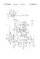
- FIG. 2is a block diagram of the base unit signal transmitter shown in FIG. 1 constructed in accordance with one aspect of the present invention
- FIGS. 3A and 3Bare block diagrams of a remote receiver unit shown in FIG. 1 according to one aspect of the present invention.
- FIGS. 4A and 4Bare detailed circuit diagrams of the transmitter shown in FIG. 2;
- FIGS. 5A, 5 B, and 5 Care detailed circuit diagrams of the receiver shown in FIGS. 3A and 3B;
- FIG. 6is a block diagram of another embodiment of a wireless high frequency signal transmission apparatus according to the present invention having a recording media.
- FIGS. 1-5Cthere is depicted a preferred aspect of the present invention which is described hereafter with reference to the transmission of audio stereo signals from an audio signal source 10 to a remote audio output device 12 .
- an audio signal embodiment of the inventive high frequency signal transmission apparatusis by example only as the present invention also encompasses the high frequency transmission of video signals and both analog and video signals in either analog or digital format.
- the source of video signalscan include an Internet media broadcast, a cable television signal feed, a television broadcast, the output of a video cassette recorder, etc.
- the audio source 10is described hereafter as a computer connected via a modem, not shown, to the Internet for receiving and downloading music or other audio signals from a remote source via conventional Internet communication
- the audio source 10may be any suitable mono or stereo audio source which provides music, data, or verbal sounds.
- the audio source 10may also be provided in different forms, other than the illustrated computer 14 and computer sound generator card 16 .
- Examples of other audio sources 10 suitable for use in the present inventioninclude conventional radio frequency transmitted audio signals from a television or radio broadcast antenna, a CD player, AM/FM tuner, tape deck, turntable, etc.
- a wireless signal transmission apparatus 20 of the present inventionincludes a base unit 22 containing a high frequency transmitter and a remote unit 24 which is capable of receiving the high frequency transmitted signal and then retransmitting or re-broadcasting the modulated signal on a lower carrier frequency to the remote audio receiver or output device 12 .
- the base unit 22is adapted to be coupled via jacks or connectors and electrical conductors to the signal source 10 , which, in this aspect of the invention, is described as being the computer 12 .
- Appropriate output jacks on the computer 14are connected to outputs on the internally mounted computer sound generating card 16 and receive plug-in connectors on electrical cables or conductors 26 .
- the cables 26would normally run as right and left channel cables to a speaker pair 28 .
- the conductors 26are plugged into left and right connectors or jacks denoted symbolically by reference number 30 on a housing containing the circuitry and components of the base unit 22 .
- Left and right audio in-jack 30such as RCA audio in-jacks, are mounted on the base unit housing for receiving the cables 26 .
- the base unit 22is also provided with a pair of left and right audio output jacks 32 only one of which is shown in FIG. 1 .
- Conductors 34 with plugs matable with the jacks or connectors 32are connected between the jacks 32 and the speaker pair 28 for generating audio sounds from the audio source 10 at the location of the audio source 10 .
- a stereo mini-input jack and stereo mini-output jackmay also be mounted on the housing of the base unit 22 for receiving mini plug connectors attached to cables.
- a headphone jackmay also be provided on the housing of the base unit 22 for connection to a portable receiver, such as a portable headphone.
- the base unit 22is provided with DC power from DC storage batteries 36 or by a conventional AC/DC adapter 38 which is plugged into a AC power source, such as a building AC outlet.
- the DC power from either the AC adapter 38 or the batteries 36are input to a regulated power supply 40 .
- a low battery indicator, such as an LED 42is connected to the regulated power supply 40 and is illuminated when battery power falls below a predetermined threshold level sufficient for operation of the base unit 22 .
- An on/off pushbutton 44is mounted on the housing of the base unit 22 for controlling the supply of power to the circuitry in the base unit 22 .
- a five LED level meter 46is also mounted on the housing of the base unit 22 to indicate the modulation of the receiving signal level.
- the modulation meter 46is driven by a sample of the left and right channel signals via the connectors 30 R and 30 L through a summing circuit 48 .
- the useris able to adjust the modulation level by adjusting the volume of the audio sound produced by the computer sound generator card 16 until it is optimal, as indicated by the maximum number of illuminated LEDs on the modulation meter 46 .
- Four green LEDsare provided for sequential illumination on increasing modulation level, with a red LED provided for a no signal indication.
- a channel select switch 50such as a slide switch or multi-position switch is switchable between four positions labeled Ch 1 , Ch 2 , Ch 3 , and Ch 4 . Each position has a red LED indicator 52 , 54 , 56 , and 58 , respectively, to indicate the selected channel.
- the incoming left and right stereo signals on channels 30 L and 30 Rare also passed to a stereo encoder circuit 60 .
- the stereo encoder circuitmay be a conventional stereo modulator IC, such as one sold by New Japan Radio Co, Ltd., model no. NJM2035. Although other types of stereo encoder circuits may also be employed, the circuit 60 generally combines the left and right channel signals into a standard composite stereo format.
- a summing circuit 62adds the left and right channel signals into a first signal.
- Another summing circuit 64forms a second signal by subtracting the right and left channel signals, with the right channel signal phase shifted 180° from the left channel signal by a phase shift circuit 66 .
- the output of the summing circuit 64is input to a balanced mixer 68 which has another input from a 38 KHz crystal oscillator 70 .
- the mixer 68modulates the subtraction product of the summing circuit 64 onto a 38 KHz subcarrier frequency.
- the 38 KHz output of the crystal oscillator 70is halved by a divide by 2 circuit 72 to form a 19 KHz subcarrier frequency. This signal is passed through a 19 KHz bandpass filter 74 to produce a 19 KHz pilot signal.
- the output of the balanced mixer 68is summed with the output of the summing circuit 62 in a summing circuit 76 .
- the output of the summing circuit 76is passed through a low pass filter 78 and input to a summing circuit 80 to produce a multiplexed stereo signal.
- the output of the summing circuit 80is processed by a limiter or automatic gain control circuit 82 and used to frequency modulate a first oscillator 84 which is preferably a 900 MHZ voltage controlled oscillator (VCO).
- VCOvoltage controlled oscillator
- a channel select switch 50 having multiple positionsis used to determine the center transmit frequency of the oscillator 84 .
- Each channel of the channel select switch 50is connected to a discrete voltage thereby controlling the output frequency of the first oscillator 84 .
- Ch 1when Ch 1 is selected by the channel select switch 50 , the first oscillator 84 outputs a center frequency of 910.0 MHZ.
- Channels 2 , 3 , and 4(Ch 2 , Ch 3 , and Ch 4 ), when individually selected by the channel switch 50 , respectively control the first oscillator 84 to output a transmit center frequency of 910.2, 910.4, and 910.6 MHZ, respectively.
- the output of the first oscillator 84is amplified to an appropriate level by an RF power amplifier 86 and filtered in a 900 MHZ bandpass filter 88 to remove harmonics before passing to an antenna 90 for transmission to the remote unit 24 .
- the output signal from the first oscillator 84is impedance matched with the antenna 90 which may be a 1 ⁇ 4 wave resonant monopole antenna tuned to the desired output frequency (900 MHZ or above).
- the antenna 90which is preferably permanently attached to the housing of the base unit 22 , radiates modulated high frequency radio waves at the selected 910.0-910.6 frequency to the remote unit 24 .
- circuitry which performs the function of the base unit 22has been described as being a stand alone device separate from the audio source 10 , it will be understood that the circuitry or components employed in the base unit 22 may also be mounted on the sound generator card 16 in a computer comprising the audio source in the present example of the invention as well as on a separate circuit board mounted within the computer housing or on a computer motherboard itself.
- the 900 MHZ modulated ISM band signal from the base unit 22is picked up at the remote unit 24 by an antenna 100 .
- the antenna 100may also be a 1 ⁇ 4 wave resonant monopole fixed to the housing of the receiver 24 .
- Other antenna typesmay also be employed for the antenna 100 .
- the 900 MHZ modulated signal received by the antenna 100is amplified by a low-noise RF amplifier 102 .
- the output of the amplifier 102is combined with the output of a first local oscillator 104 in a first balanced mixer circuit 106 .
- the first mixer 106provides two outputs, namely, the sum and the difference of the two input frequencies.
- the sum signalis attenuated by a 61 MHZ bandpass filter and amplifier circuit 108 .
- the filter and amplifier circuit 108amplifies and passes the difference frequency of 61 MHZ to a second balanced mixer 110 .
- the first oscillator 104is preferably a digitally tuned voltage control oscillator (VCO).
- VCOvoltage control oscillator
- the first oscillator 104is made to oscillate at a frequency that is 61 MHZ above the received frequency. For example, if the received frequency is 905 MHZ, the first oscillator operates at a frequency of 966 MHZ.
- the amplified and filtered output of the first oscillator 104which is now at 61 MHZ, is mixed with the output of a second local oscillator 112 tuned to a 71.7 MHZ frequency in the second balanced mixer 110 .
- the second balanced mixer 110produces sum and difference outputs.
- the sum frequency of 132.7 MHZ(in the present example) is attenuated by a 10.7 MHZ ceramic filter 114 ; while a difference frequency 10.7 MHZ is passed through the ceramic bandpass filter 114 as a 10.7 MHZ carrier frequency.
- the 10.7 MHZ signalstill maintains the audio frequency modulation that was transmitted by the base unit 22 .
- the signalhas been simply “mixed down” from the 900 MHZ ISM band to 10.7 MHZ.
- This conversion from the 900 MHZ frequency to a 10.7 MHZ frequencyavoids the use of modulation and demodulation circuits which impose imperfections into the transmitted signal. Converting the center transmit frequency rather than modulating and demodulating as in previous high frequency signal transmission systems utilizes less expensive retransmission circuitry thereby reducing the cost of the signal transmission device as well as providing better signal quality.
- the 10.7 MHZ modulated carrier signalis routed through a limiter amplifier 116 which not only provides substantial gain, but also removes variations in the amplitude of the carrier signal. Coupled to the output of the limiter amplifier 116 is a quadrature-type FM frequency detector 118 which produces a voltage that is proportional to the frequency of the 10.7 MHZ carrier signal. Specifically, the output voltage of the FM detector 118 is proportional to the composite stereo FM modulation that was applied to the 900 MHZ signal in the base unit 22 .
- the output of the FM detector 118is processed by a stereo decoder or integrated circuit 120 , such as a PLL FM multiplex demodulator sold by Sanyo as model no. LA3335M.
- the individual left and right audio signals from the stereo decoder 120each pass through a separate 19 KHz low pass notch filter 122 and 124 in order to remove 19 KHz “pilot tone” used in decoding the composite stereo signal.
- the left and right audio signalspass through a stereo headphone amplifier 126 for output to a stereo headphone jack 128 mounted on the housing of the remote unit 24 .
- the amplifier 126in the preferred aspect of the present invention, employs an electronic volume control that enables the gain of both left and right channels to be adjusted with a separate volume control switch or knob 130 mounted on the remote unit 24 .
- the stereo decoder 120also has an output 121 that indicates successful detection of the 19 KHz pilot tone sent by the base unit 22 . This output is used to operate an indicator or LED 132 which works as a “stereo” or “valid signal received” indicator. If the pilot tone is not successfully decoded, an output 123 from the stereo decoder 120 is used to disable the transmitter of the remote unit 24 and mute the headphone audio output via a mute signal 134 coupled to the stereo headphone amplifier 126 . The remote transmitter and the headphones 129 return to normal operation once the pilot signal is successfully decoded or received.
- the output of the FM detector 118is also used for automatic frequency control (AFC).
- AFCautomatic frequency control
- By running the output of the FM detector 118 through a low pass filter 140a signal is obtained that is proportional to the “center frequency” of the 10.7 MHZ carrier signal. If the first and/or second oscillator 104 and 112 drift off frequency, the 10.7 MHZ signal will also be different from the 10.7 MHZ center frequency.
- By determining the filtered or average FM detector output from the low pass filter 140it is possible to determine if the detected 10.7 MHZ signal frequency is too high or too low.
- a window detector circuit 142which compares the filtered FM detector output from the filter 140 with two reference voltages Vref 1 and Vref 2 .
- Vref 1being slightly lower than nominal frequency
- Vref 2being slightly higher than nominal frequency.
- the window detector circuit 142has two outputs that can be decoded to indicate whether the input voltage is below the lower reference frequency (Vref 1 ), above the upper reference frequency (Vref 2 ), or in the window “in between” the lower reference frequency and the upper reference frequency.
- a controller or microcontroller 144executes a stored program to accomplish this decoding.
- the microcontroller 144outputs signals to a eight bit digital to analog converter 146 which is used to tune or adjust the frequency of the first local oscillator 104 .
- the controller 144is programmed to make corrections to the frequency of the first local oscillator 104 as indicated by the decoded window detector 142 output information.
- the objectiveis to maintain the output of the second mixer 110 at exactly 10.7 MHZ.
- the controller 144linearly increments the frequency of the first local oscillator 104 until the output of the second mixer 110 is exactly 10.7 MHZ as indicated by the output of the window detector 142 .
- the software control program executed by the controller 144simply maintains the frequency by incrementing up or decrementing down the magnitude of control signals supplied to the digital to analog converter 146 as indicated by the decoded output of the window detector 142 .
- the window detector 142is only useful within a certain neighborhood of the desired frequency, another detector 148 is also required for operation elsewhere.
- This other detector 148is preferably a 19 KHz peak detector 148 which receives the output of the FM detector from a 19 KHz bandpass filter 149 . If the first and second local oscillators 104 and 112 are off frequency by a large amount, as indicated by a failure to detect the 19 KHz pilot tone sent by the base unit 22 , the controller 144 will simply start tuning the first local oscillator 104 up in frequency until the 19 KHz pilot tone is detected by the detector 148 .
- the controller 144looks at the outputs of the window detector 142 to determine if the frequency is too far off and, if so, which direction the first local oscillator 104 must be tuned in order to correct the frequency. It should be noted that if the first local oscillator 104 is adjusted to the upper limit of a tuning range without locking onto the pilot tone signal, the first local oscillator 104 will simple wrap around and start ramping up from its lowest tunable frequency.
- a pushbutton 150 labeled “AUTOSCAN”is optionally connected as an input to the controller 144 .
- the pushbutton 150allows the operator to force a new “AUTOSCAN” when the microcontroller 144 increments the frequency of the first local oscillator 104 to fine tune the output frequency of the second balanced mixer 110 to the center 10.7 MHZ frequency.
- this push button 150should seldom need to be used since the automatic fine tuning control circuit described above insures that the remote unit 24 will find the transmitted center frequency automatically.
- the 10.7 MHZ signal output from the filter 114still maintains the stereo frequency modulation that was transmitted by the base unit 22 .
- the stereo frequency modulationhas simply been “mixed down” or “converted down” from the 900 MHZ band to 10.7 MHZ.
- Transmitter circuitry, described hereafter, in the remote unit 24amplifies this modulated 10.7 MHZ signal, mixes it back up to the low end of the FM broadcast band, amplifies and filters it before transmitting or re-broadcasting the modulated signal carrying the stereo frequency modulation to a remote audio output device, such as a RF receiver.
- the transmitter portion of the remote unit 24includes a high gain limiter amplifier filter 154 tuned to 10.7 MHZ.
- the limiting action of the limiter amplifier 154has the effect of making the transmitter output level largely independent of the strength of the signal received on the 900 MHZ band.
- the limited 10.7 MHZ signalis next mixed in a balanced transmit mixer 156 with the output of a second oscillator 160 .
- the second oscillator 160is a crystal oscillator designed to operate at one of four difference frequencies as selected by the controller 144 via an input pushbutton 162 operated by the user.
- the controller 144outputs signals on channel output lines selecting one of four difference crystals which are switched into the second oscillator 160 to make it operate 10.7 MHZ below of the available low end FM broadcast band frequencies of 88.1, 88.3, 88.5, and 88.7 MHZ.
- Individual FM band channel indicators 164such as LEDs, are coupled to each channel output line from the controller 144 to indicate the selected channel.
- the output of the transmit mixer 156includes once again of sum and difference outputs. This time, however, the sum term is of interest. For example, if the desired transmit channel is 88.1 MHZ, the operator selects the appropriate crystal, i.e., 77.4 MHZ, by an appropriate number of separate depressions or the channel pushbutton 162 until the desired transmit channel corresponding to 77.4 MHZ as shown by one output LED 164 is reached.
- the difference term output from the transmit mixer 156is attenuated by a tuned 88 MHZ amplifier while the sum term output is amplified. This 88.1 modulated MHZ signal is then passed through a bandpass filter antenna matching network circuit 168 and applied to an FM broadcast band transmit antenna 170 .
- This signal which is broadcast at the low end of the FM broadcast band (88 MHZ)can be received using any standard FM broadcast band receiver (mono or stereo). If the receiver is a stereo receiver, it will reproduce the stereo program material.
- the audio receiver or output device 12shown in FIG. 1, which is capable of receiving the re-broadcasted transmit signal from the antenna 170 may be a conventional AM/FM stereo receiver, AM/FM radio or even a wireless headphone having demodulation circuitry mounted therein, similar to that described above for the stereo decoder 120 and headphone jack 128 mounted on the housing of the remote unit 24 .
- electrical power to the remote unit 24is provided through a conventional AC/DC adapter 172 or conventional storage batteries 174 .
- An on/off switch 176is also mounted on the housing of the remote unit 24 to control the application of power to a regulated power supply 178 mounted within the housing of the remote unit 24 .
- a low battery indicator, such as a LED indicator 180is also mounted on the housing of the remote unit 24 to indicate when the battery level falls below a predetermined threshold sufficient for proper operation of the remote unit 24 .
- the apparatus of the present inventionwith minimal alteration may also be utilized to transmit high frequency digital signals.
- the audio signalsregardless of the signal format from the audio source 10 , the audio signals, whether in analog or digital form, are modulated onto the high frequency carrier signal and transmitted to the remote unit 24 .
- the incoming modulated signalcan be retransmitted to the remote output device in one of two forms, namely, either in analog or digital format depending upon the nature of the output device.
- the output devicesuch as a television or AM/FM stereo receiver
- the modulated digital signals received by the remote unit 24can be merely transmitted at the new carrier frequency in the same manner as the incoming audio signal described above.
- a digital to analog converter or codeccan be employed, for example, between the output of the 61 MHZ bandpass filter/amplifier 108 and the second balanced mixer 110 in the remote unit 24 .
- the digital signalsare converted to analog form, but remain as a modulated signal on the new down converted frequency which is then up converted and retransmitted by the remote unit 24 to the further remote output device as described above.
- a reverse or analog to digital converter or codecmay be employed in the remote unit 24 to convert the incoming digital modulated signals to analog modulated signals.
- Video signalsare typically in MTSC standard format and may have stereo audio accompaniment.
- the video signalsare transmitted on a 2.4 GHz carrier with the audio signals transmitted on a 38 MHZ subcarrier to the remote unit 24 .
- the video signalsare down converted by the remote unit 24 to a frequency band consistent with television or video broadcast format and then retransmitted to an output video device, such as a television, monitor, etc.
- the recorder 190may be any suitable recording device capable of receiving, storing and re-outputting digital and/or analog signals representing either audio or visual source programs or data.
- the recorder 190may constitute a conventional video cassette recorder for storing video and audio signals in analog form.
- the recorder 190may be a digital memory device such as, for example, a Rio-MP3 minidisc player manufactured by Diamond Multimedia.
- the only change necessary to the remote unit 24is the addition of an analog to digital converter or codec coupled to the output of stereo decoder 120 for converting audio signals to digital format.
- the codecis not required.
- the analog to digital conversionmay take place directly in the recorder 190 .
- the recorder 190is also capable of outputting stored signals to the remote unit 24 upon receiving an input from a user, such as via a depression of a pushbutton or switch on the recorder 190 or remote unit 24 or upon receiving a signal from a remote source, such as the user's service provider assuming that a suitable Internet connection is made to either the recorder 190 or remote unit 24 .
- the recorder 190outputs the stored signal information to the remote unit 24 which then reconstitutes the signals as analog or digital signals depending upon the nature of the output device and modulates the signals via the second mixer 110 at a suitable subcarrier frequency such as 10.7 MHz subcarrier frequency for audio signals or at a 2.4 GHz frequency, using a different second oscillator, for video signals.
- the audio signalsare transmitted on a lower frequency subcarrier, such as 38 MHZ frequency, with the higher frequency video modulated signals.
- This signal streamis then transmitted through the transmitter section of the remote unit 24 , in the same manner as described above and shown in FIG. 3B for audio signals, to the remote end device which has the capability to demodulate the received signals and generate appropriate video images and/or audio sounds.
- remote unit 24 and the recorder 190are depicted as separate elements in FIG. 6, the circuitry and elements of both the remote unit 24 and the recorder 190 may be combined into a single device, such as a modified remote unit having an internally mounted recorder.
- a unique wireless high frequency signal transmission apparatuscapable of receiving audio and/or video signals from a suitable source, transmitting the received signals via a high frequency carrier to a remote receiver which in turn converts the modulated signals to a different frequency before retransmitting the modulated signals to a remote receiver capable of receiving and outputting the audio sounds or video images.
- the unique wireless transmission system of the present inventionmakes use of high frequency (900 MHz) carrier for transmissions to the remote unit and lower frequencies for transmissions from the remote unit to the end receiver.
- the present apparatusalso provides multiple channel selection of both the high frequency and low frequency transmission signals thereby ensuring proper transmission of the signals despite any interference.
- the high frequency transmission apparatus of the present inventionmakes unique use of a wireless connection between the remote unit and a further remote receiver thereby enabling the apparatus of the present invention to be employed in a completely different area of a building or home from the remote receiver.
- the apparatus of the present inventionis also ideally suited for receiving streaming Internet broadcast media signals and then re-broadcasting the signals through the remote unit to a remote receiver which typically can be a user's stereo system, a pair of wireless headphones containing appropriate stereo demodulation circuitry a television, etc.
Landscapes
- Engineering & Computer Science (AREA)
- Signal Processing (AREA)
- Computer Networks & Wireless Communication (AREA)
- Multimedia (AREA)
- Transmitters (AREA)
- Channel Selection Circuits, Automatic Tuning Circuits (AREA)
Abstract
Description
Claims (22)
Priority Applications (3)
| Application Number | Priority Date | Filing Date | Title |
|---|---|---|---|
| US09/419,178US6256303B1 (en) | 1999-10-15 | 1999-10-15 | Wireless broadcast link to remote receiver |
| PCT/US2000/026021WO2001030008A2 (en) | 1999-10-15 | 2000-09-21 | Wireless 900 mhz broadcast link to remote receiver |
| AU76043/00AAU7604300A (en) | 1999-10-15 | 2000-09-21 | Wireless 900 mhz broadcast link to remote receiver |
Applications Claiming Priority (1)
| Application Number | Priority Date | Filing Date | Title |
|---|---|---|---|
| US09/419,178US6256303B1 (en) | 1999-10-15 | 1999-10-15 | Wireless broadcast link to remote receiver |
Publications (1)
| Publication Number | Publication Date |
|---|---|
| US6256303B1true US6256303B1 (en) | 2001-07-03 |
Family
ID=23661133
Family Applications (1)
| Application Number | Title | Priority Date | Filing Date |
|---|---|---|---|
| US09/419,178Expired - LifetimeUS6256303B1 (en) | 1999-10-15 | 1999-10-15 | Wireless broadcast link to remote receiver |
Country Status (3)
| Country | Link |
|---|---|
| US (1) | US6256303B1 (en) |
| AU (1) | AU7604300A (en) |
| WO (1) | WO2001030008A2 (en) |
Cited By (76)
| Publication number | Priority date | Publication date | Assignee | Title |
|---|---|---|---|---|
| US20020098813A1 (en)* | 2000-11-01 | 2002-07-25 | George Likourezos | Apparatus and method for generating and transmitting an RF modulated signal having a modulation frequency within the AM and/or FM band |
| US20030031323A1 (en)* | 2001-07-11 | 2003-02-13 | Pace Ronald G. | Multiple signal carrier transmission apparatus and method |
| US20030181182A1 (en)* | 2002-03-22 | 2003-09-25 | Hoi Ho Sing | Receiver for wireless transmission system |
| WO2003098851A1 (en)* | 2002-05-14 | 2003-11-27 | Seekernet Incorporated | Lprf device wake up using wireless tag |
| US20040082296A1 (en)* | 2000-12-22 | 2004-04-29 | Seekernet Incorporated | Network Formation in Asset-Tracking System Based on Asset Class |
| US20040086141A1 (en)* | 2002-08-26 | 2004-05-06 | Robinson Arthur E. | Wearable buddy audio system |
| US20040136699A1 (en)* | 2003-01-13 | 2004-07-15 | Ross Demetrius Ramone | Digital prismatic disc format |
| US20040235566A1 (en)* | 2002-07-31 | 2004-11-25 | Intec, Inc. | Video game controller with integrated video display |
| US20040253925A1 (en)* | 2001-08-13 | 2004-12-16 | Caffrey John Justin | Method and apparatus for transmitting audio and non-audio information with error correction |
| US20050047071A1 (en)* | 2003-08-26 | 2005-03-03 | Bobby Tse Chun Hin | Wireless transmission interface and method |
| US20050093702A1 (en)* | 2000-12-22 | 2005-05-05 | Twitchell Robert W.Jr. | Manufacture of LPRF device wake up using wireless tag |
| US20050093703A1 (en)* | 2000-12-22 | 2005-05-05 | Twitchell Robert W.Jr. | Systems and methods having LPRF device wake up using wireless tag |
| US20050135634A1 (en)* | 2003-12-22 | 2005-06-23 | Eastern Asia Technology Limited | Wireless transmission device of surround sound stereo system |
| US20050186993A1 (en)* | 2004-02-24 | 2005-08-25 | Yueh Wen H. | Communication apparatus for playing sound signals |
| US20050215280A1 (en)* | 2000-12-22 | 2005-09-29 | Twitchell Jr Robert W | Lprf device wake up using wireless tag |
| US20050220310A1 (en)* | 2004-03-30 | 2005-10-06 | Mcgrath William R | Technique and device for through-the-wall audio surveillance |
| US20060018274A1 (en)* | 2000-12-22 | 2006-01-26 | Seekernet Incorporated | Communications within population of wireless transceivers based on common designation |
| US20060023678A1 (en)* | 2000-12-22 | 2006-02-02 | Seekernet Incorporated | Forming communication cluster of wireless ad hoc network based on common designation |
| US20060023679A1 (en)* | 2000-12-22 | 2006-02-02 | Seekernet Incorporated | Propagating ad hoc wireless networks based on common designation and routine |
| US7088740B1 (en) | 2000-12-21 | 2006-08-08 | Bae Systems Information And Electronic Systems Integration Inc | Digital FM radio system |
| US7095866B1 (en)* | 2001-07-11 | 2006-08-22 | Akoo, Inc. | Wireless 900 MHz broadcast link |
| US20060237490A1 (en)* | 2005-01-10 | 2006-10-26 | Seekernet Incorporated | Keyhole communication device for tracking and monitoring shipping container and contents thereof |
| US7143939B2 (en)* | 2000-12-19 | 2006-12-05 | Intel Corporation | Wireless music device and method therefor |
| US20060274698A1 (en)* | 2005-06-03 | 2006-12-07 | Terahop Networks, Inc. | Using wake-up receivers for soft hand-off in wireless communications |
| US20060276963A1 (en)* | 2005-06-03 | 2006-12-07 | Terahop Networks, Inc. | Network aided terrestrial triangulation using stars (natts) |
| US20060282217A1 (en)* | 2005-06-03 | 2006-12-14 | Terahop Networks, Inc. | Network aided terrestrial triangulation using stars (natts) |
| US20060287008A1 (en)* | 2005-06-17 | 2006-12-21 | Terahop Networks, Inc. | Remote sensor interface (rsi) having power conservative transceiver for transmitting and receiving wakeup signals |
| US20070001898A1 (en)* | 2005-06-16 | 2007-01-04 | Terahop Networks, Inc. | operating gps receivers in gps-adverse environment |
| US20070004331A1 (en)* | 2005-06-16 | 2007-01-04 | Terahop Networks, Inc. | tactical gps denial and denial detection system |
| US20070002808A1 (en)* | 2000-12-22 | 2007-01-04 | Seekernet Incorporated | Transmitting sensor-acquired data using step-power filtering |
| US20070004330A1 (en)* | 2005-06-16 | 2007-01-04 | Terahop Networks, Inc. | Selective gps denial system |
| US20070004431A1 (en)* | 2000-12-22 | 2007-01-04 | Seekernet Incorporated | Forming ad hoc rsi networks among transceivers sharing common designation |
| US20070043807A1 (en)* | 2005-08-18 | 2007-02-22 | Terahop Networks, Inc. | All WEATHER HOUSING ASSEMBLY FOR ELECTRONIC COMPONENTS |
| US20070041333A1 (en)* | 2005-08-18 | 2007-02-22 | Terahop Networks, Inc. | Sensor networks for monitoring pipelines and power lines |
| US20070060195A1 (en)* | 2004-02-24 | 2007-03-15 | Hsiang Yueh W | Communication apparatus for playing sound signals |
| US20070069885A1 (en)* | 2005-06-17 | 2007-03-29 | Terahop Networks, Inc. | Event-driven mobile hazmat monitoring |
| US20070099629A1 (en)* | 2005-10-31 | 2007-05-03 | Terahop Networks, Inc. | Using gps and ranging to determine relative elevation of an asset |
| US20070155327A1 (en)* | 2006-01-01 | 2007-07-05 | Terahop Networks, Inc. | Determining presence of radio frequency communication device |
| US20070159999A1 (en)* | 2000-12-22 | 2007-07-12 | Terahop Networks, Inc. | Intelligent node communication using network formation messages in a mobile Ad hoc network |
| WO2007090169A3 (en)* | 2006-01-31 | 2008-04-10 | Aerielle Technologies Inc | Am/fm/sw receiver coupled with fm transmitter for personal multimedia players for listening and recording |
| US20080136624A1 (en)* | 2005-01-10 | 2008-06-12 | Seekernet Incorporated | Keyhole communication device for tracking and monitoring shipping container and contents thereof |
| US20080175403A1 (en)* | 2007-01-22 | 2008-07-24 | Min-Liang Tan | Wireless Audio Sharing |
| US20080176512A1 (en)* | 2007-01-22 | 2008-07-24 | Min-Liang Tan | Wireless sharing of audio files and information for streamlined purchasing |
| US20080176511A1 (en)* | 2007-01-22 | 2008-07-24 | Min-Liang Tan | Wireless sharing of audio files and related information |
| US20080181148A1 (en)* | 2007-01-08 | 2008-07-31 | Freesystems Pte., Ltd. | Multi-node media content relay system |
| US20090003287A1 (en)* | 2007-06-28 | 2009-01-01 | Yoshiyuki Arakawa | Method of translating cellular carriers |
| US20090122737A1 (en)* | 2007-02-21 | 2009-05-14 | Terahop Networks, Inc. | Mesh network control using common designation wake-up |
| US20090121841A1 (en)* | 2000-12-22 | 2009-05-14 | Terahop Networks, Inc. | Screening transmissions for power level and object identifier in asset monitoring and tracking systems |
| US20090129306A1 (en)* | 2007-02-21 | 2009-05-21 | Terahop Networks, Inc. | Wake-up broadcast including network information in common designation ad hoc wireless networking |
| US7563991B2 (en) | 2005-06-08 | 2009-07-21 | Terahop Networks, Inc. | All weather housing assembly for electronic components |
| US7574300B2 (en) | 2005-06-16 | 2009-08-11 | Terahop Networks, Inc. | GPS denial device detection and location system |
| US20090290512A1 (en)* | 2000-12-22 | 2009-11-26 | Terahope Networks, Inc. | Wireless data communications network system for tracking containers |
| US20100067420A1 (en)* | 2000-12-22 | 2010-03-18 | Terahop Networks, Inc. | Lprf device wake up using wireless tag |
| US20100076578A1 (en)* | 2002-08-30 | 2010-03-25 | Sony Corporation | Remote user interface for media player |
| US20100150026A1 (en)* | 2008-05-16 | 2010-06-17 | Robins David S | Updating node presence based on communication pathway |
| US20100214077A1 (en)* | 2005-07-29 | 2010-08-26 | Terry Daniel J | Reusable locking body, of bolt-type seal lock, having open-ended passageway and u-shaped bolt |
| US20100238940A1 (en)* | 2009-01-28 | 2010-09-23 | Koop Lamonte Peter | Ascertaining presence in wireless networks |
| US20100265042A1 (en)* | 2009-02-05 | 2010-10-21 | Koop Lamonte Peter | Conjoined class-based networking |
| US7830850B2 (en) | 2000-12-22 | 2010-11-09 | Terahop Networks, Inc. | Class-switching in class-based data communcations network |
| US20100330930A1 (en)* | 2000-12-22 | 2010-12-30 | Twitchell Robert W | Lprf device wake up using wireless tag |
| US7940716B2 (en) | 2005-07-01 | 2011-05-10 | Terahop Networks, Inc. | Maintaining information facilitating deterministic network routing |
| US20110166961A1 (en)* | 2007-01-22 | 2011-07-07 | Jook, Inc. | Wireless sharing of audio files and information for streamlined purchasing |
| CN101803178B (en)* | 2007-06-28 | 2013-03-13 | 朗讯科技公司 | Method of translating cellular carriers |
| TWI395423B (en)* | 2008-01-04 | 2013-05-01 | Jook Inc | Wireless communication device |
| US20130117693A1 (en)* | 2011-08-25 | 2013-05-09 | Jeff Anderson | Easy sharing of wireless audio signals |
| CN102014086B (en)* | 2009-09-08 | 2013-07-24 | 电信科学技术研究院 | Base station signal transmission processing method and base station transmitter |
| US8755763B2 (en) | 1998-01-22 | 2014-06-17 | Black Hills Media | Method and device for an internet radio capable of obtaining playlist content from a content server |
| US9516370B1 (en) | 2004-05-05 | 2016-12-06 | Black Hills Media, Llc | Method, device, and system for directing a wireless speaker from a mobile phone to receive and render a playlist from a content server on the internet |
| US9532310B2 (en) | 2008-12-25 | 2016-12-27 | Google Inc. | Receiver state estimation in a duty cycled radio |
| US9584591B1 (en) | 2004-05-05 | 2017-02-28 | Black Hills Media, Llc | Method and device for sharing a playlist at a dedicated media player device |
| US9615147B2 (en) | 2010-05-17 | 2017-04-04 | Flir Systems, Inc. | Multisensory meter system |
| US9860839B2 (en) | 2004-05-27 | 2018-01-02 | Google Llc | Wireless transceiver |
| US10637575B2 (en) | 2016-05-25 | 2020-04-28 | Wisconsin Alumni Research Foundation | Spatial location indoors using standard fluorescent fixtures |
| US10664792B2 (en) | 2008-05-16 | 2020-05-26 | Google Llc | Maintaining information facilitating deterministic network routing |
| US10693760B2 (en) | 2013-06-25 | 2020-06-23 | Google Llc | Fabric network |
| US11082265B2 (en)* | 2019-07-31 | 2021-08-03 | At&T Intellectual Property I, L.P. | Time synchronization of mobile channel sounding system |
Citations (12)
| Publication number | Priority date | Publication date | Assignee | Title |
|---|---|---|---|---|
| US5272525A (en) | 1991-03-07 | 1993-12-21 | Recoton Corporation | System for local wireless transmission of signals at frequencies above 900 MHz |
| US5299264A (en) | 1991-08-21 | 1994-03-29 | L. S. Research, Inc. | System for short-range transmission of signals over the air using a high frequency carrier |
| US5319716A (en) | 1991-09-17 | 1994-06-07 | Recoton Corporation | Wireless CD/automobile radio adapter |
| US5349386A (en) | 1991-03-07 | 1994-09-20 | Recoton Corporation | Wireless signal transmission systems, methods and apparatus |
| US5410735A (en) | 1992-01-17 | 1995-04-25 | Borchardt; Robert L. | Wireless signal transmission systems, methods and apparatus |
| US5477539A (en)* | 1993-07-23 | 1995-12-19 | Ericsson Inc. | Narrow band simulcast system having low speed data distribution |
| US5491839A (en) | 1991-08-21 | 1996-02-13 | L. S. Research, Inc. | System for short range transmission of a plurality of signals simultaneously over the air using high frequency carriers |
| US5619582A (en)* | 1996-01-16 | 1997-04-08 | Oltman; Randy | Enhanced concert audio process utilizing a synchronized headgear system |
| US5666658A (en) | 1991-03-07 | 1997-09-09 | Recoton Corporation | Wireless signal transmission system, method and apparatus |
| US5768696A (en) | 1995-12-18 | 1998-06-16 | Golden Eagle Electronics Manufactory Ltd. | Wireless 900 MHz monitor system |
| US6067039A (en)* | 1998-11-30 | 2000-05-23 | Pacific Design Engineering (1996 ( Ltd. | Systems and methods for determining the distance between two locations |
| US6137995A (en)* | 1998-12-08 | 2000-10-24 | Motorola, Inc. | Circuit and method of generating a phase locked loop signal having an offset reference |
- 1999
- 1999-10-15USUS09/419,178patent/US6256303B1/ennot_activeExpired - Lifetime
- 2000
- 2000-09-21AUAU76043/00Apatent/AU7604300A/ennot_activeAbandoned
- 2000-09-21WOPCT/US2000/026021patent/WO2001030008A2/enactiveApplication Filing
Patent Citations (13)
| Publication number | Priority date | Publication date | Assignee | Title |
|---|---|---|---|---|
| US5666658A (en) | 1991-03-07 | 1997-09-09 | Recoton Corporation | Wireless signal transmission system, method and apparatus |
| US5349386A (en) | 1991-03-07 | 1994-09-20 | Recoton Corporation | Wireless signal transmission systems, methods and apparatus |
| US5272525A (en) | 1991-03-07 | 1993-12-21 | Recoton Corporation | System for local wireless transmission of signals at frequencies above 900 MHz |
| US5299264A (en) | 1991-08-21 | 1994-03-29 | L. S. Research, Inc. | System for short-range transmission of signals over the air using a high frequency carrier |
| US5491839A (en) | 1991-08-21 | 1996-02-13 | L. S. Research, Inc. | System for short range transmission of a plurality of signals simultaneously over the air using high frequency carriers |
| US5581617A (en) | 1991-08-21 | 1996-12-03 | L. S. Research, Inc. | System for short-range transmission of signals over the air using a high frequency carrier |
| US5319716A (en) | 1991-09-17 | 1994-06-07 | Recoton Corporation | Wireless CD/automobile radio adapter |
| US5410735A (en) | 1992-01-17 | 1995-04-25 | Borchardt; Robert L. | Wireless signal transmission systems, methods and apparatus |
| US5477539A (en)* | 1993-07-23 | 1995-12-19 | Ericsson Inc. | Narrow band simulcast system having low speed data distribution |
| US5768696A (en) | 1995-12-18 | 1998-06-16 | Golden Eagle Electronics Manufactory Ltd. | Wireless 900 MHz monitor system |
| US5619582A (en)* | 1996-01-16 | 1997-04-08 | Oltman; Randy | Enhanced concert audio process utilizing a synchronized headgear system |
| US6067039A (en)* | 1998-11-30 | 2000-05-23 | Pacific Design Engineering (1996 ( Ltd. | Systems and methods for determining the distance between two locations |
| US6137995A (en)* | 1998-12-08 | 2000-10-24 | Motorola, Inc. | Circuit and method of generating a phase locked loop signal having an offset reference |
Cited By (188)
| Publication number | Priority date | Publication date | Assignee | Title |
|---|---|---|---|---|
| US9397627B2 (en) | 1998-01-22 | 2016-07-19 | Black Hills Media, Llc | Network-enabled audio device |
| US9312827B2 (en) | 1998-01-22 | 2016-04-12 | Black Hills Media, Llc | Network enabled audio device and radio site |
| US8918480B2 (en) | 1998-01-22 | 2014-12-23 | Black Hills Media, Llc | Method, system, and device for the distribution of internet radio content |
| US8792850B2 (en) | 1998-01-22 | 2014-07-29 | Black Hills Media | Method and device for obtaining playlist content over a network |
| US8755763B2 (en) | 1998-01-22 | 2014-06-17 | Black Hills Media | Method and device for an internet radio capable of obtaining playlist content from a content server |
| US20020098813A1 (en)* | 2000-11-01 | 2002-07-25 | George Likourezos | Apparatus and method for generating and transmitting an RF modulated signal having a modulation frequency within the AM and/or FM band |
| US7143939B2 (en)* | 2000-12-19 | 2006-12-05 | Intel Corporation | Wireless music device and method therefor |
| US7088740B1 (en) | 2000-12-21 | 2006-08-08 | Bae Systems Information And Electronic Systems Integration Inc | Digital FM radio system |
| USRE43610E1 (en) | 2000-12-21 | 2012-08-28 | Frantorf Investments Gmbh, Llc | Digital FM radio system |
| US8331862B2 (en) | 2000-12-22 | 2012-12-11 | Google Inc. | Radio frequency identification based networks |
| US8218514B2 (en) | 2000-12-22 | 2012-07-10 | Google, Inc. | Wireless data communications network system for tracking containers |
| US20050093703A1 (en)* | 2000-12-22 | 2005-05-05 | Twitchell Robert W.Jr. | Systems and methods having LPRF device wake up using wireless tag |
| US20100214074A1 (en)* | 2000-12-22 | 2010-08-26 | Terahop Networks, Inc. | Lprf device wake up using wireless tag |
| US6934540B2 (en) | 2000-12-22 | 2005-08-23 | Seekernet, Inc. | Network formation in asset-tracking system based on asset class |
| US20100219939A1 (en)* | 2000-12-22 | 2010-09-02 | Terahop Networks, Inc. | Screening transmissions for power level and object identifier in asset monitoring and tracking systems |
| US20050215280A1 (en)* | 2000-12-22 | 2005-09-29 | Twitchell Jr Robert W | Lprf device wake up using wireless tag |
| US20100219938A1 (en)* | 2000-12-22 | 2010-09-02 | Terahop Networks, Inc. | Screening transmissions for power level and object identifier in asset monitoring and tracking systems |
| US20090267770A1 (en)* | 2000-12-22 | 2009-10-29 | Terahop Networks, Inc. | Lprf device wake up using wireless tag |
| US20060018274A1 (en)* | 2000-12-22 | 2006-01-26 | Seekernet Incorporated | Communications within population of wireless transceivers based on common designation |
| US20060023678A1 (en)* | 2000-12-22 | 2006-02-02 | Seekernet Incorporated | Forming communication cluster of wireless ad hoc network based on common designation |
| US20060023679A1 (en)* | 2000-12-22 | 2006-02-02 | Seekernet Incorporated | Propagating ad hoc wireless networks based on common designation and routine |
| US7746838B2 (en) | 2000-12-22 | 2010-06-29 | Terahop Networks, Inc. | Logically distinct wireless data communication networks sharing gateway for communicating with external networks |
| US20090237216A1 (en)* | 2000-12-22 | 2009-09-24 | Terahop Networks, Inc. | Lprf device wake up using wireless tag |
| US20100232320A1 (en)* | 2000-12-22 | 2010-09-16 | Twitchell Jr Robert W | Wireless data communications network system for tracking container |
| US7133704B2 (en) | 2000-12-22 | 2006-11-07 | Terahop Networks, Inc. | Manufacture of LPRF device wake up using wireless tag |
| US7830852B2 (en) | 2000-12-22 | 2010-11-09 | Terahop Networks, Inc. | Automatic and dynamic changing of class in class-based asset tracking and monitoring systems |
| US20050093702A1 (en)* | 2000-12-22 | 2005-05-05 | Twitchell Robert W.Jr. | Manufacture of LPRF device wake up using wireless tag |
| US7430437B2 (en) | 2000-12-22 | 2008-09-30 | Terahop Networks, Inc. | Transmitting sensor-acquired data using step-power filtering |
| US7742745B2 (en) | 2000-12-22 | 2010-06-22 | Terahop Networks, Inc. | LPRF device wake up using wireless tag |
| US20100231381A1 (en)* | 2000-12-22 | 2010-09-16 | Terahop Networks, Inc. | Lprf device wake up using wireless tag |
| US20100141401A1 (en)* | 2000-12-22 | 2010-06-10 | Terahop Networks, Inc. | Lprf device wake up using wireless tag |
| US7155264B2 (en) | 2000-12-22 | 2006-12-26 | Terahop Networks, Inc. | Systems and methods having LPRF device wake up using wireless tag |
| US7733818B2 (en) | 2000-12-22 | 2010-06-08 | Terahop Networks, Inc. | Intelligent node communication using network formation messages in a mobile Ad hoc network |
| US20100130267A1 (en)* | 2000-12-22 | 2010-05-27 | Terahop Networks, Inc. | Lprf device wake up using wireless tag |
| US20070002808A1 (en)* | 2000-12-22 | 2007-01-04 | Seekernet Incorporated | Transmitting sensor-acquired data using step-power filtering |
| US20100121862A1 (en)* | 2000-12-22 | 2010-05-13 | Terahop Networks, Inc. | Lprf device wake up using wireless tag |
| US20070004431A1 (en)* | 2000-12-22 | 2007-01-04 | Seekernet Incorporated | Forming ad hoc rsi networks among transceivers sharing common designation |
| US20100330930A1 (en)* | 2000-12-22 | 2010-12-30 | Twitchell Robert W | Lprf device wake up using wireless tag |
| US20100250460A1 (en)* | 2000-12-22 | 2010-09-30 | Twitchell Jr Robert W | Lprf device wake up using wireless tag |
| US20100067420A1 (en)* | 2000-12-22 | 2010-03-18 | Terahop Networks, Inc. | Lprf device wake up using wireless tag |
| US20100260087A1 (en)* | 2000-12-22 | 2010-10-14 | Twitchell Jr Robert W | Lprf device wake up using wireless tag |
| US20100007470A1 (en)* | 2000-12-22 | 2010-01-14 | Terahop Networks, Inc. | Lprf device wake up using wireless tag |
| US7200132B2 (en) | 2000-12-22 | 2007-04-03 | Terahop Networks, Inc. | Forming ad hoc RSI networks among transceivers sharing common designation |
| US7209771B2 (en) | 2000-12-22 | 2007-04-24 | Terahop Networks, Inc. | Battery powered wireless transceiver having LPRF component and second wake up receiver |
| US7209468B2 (en) | 2000-12-22 | 2007-04-24 | Terahop Networks, Inc. | Forming communication cluster of wireless AD HOC network based on common designation |
| US7940736B2 (en) | 2000-12-22 | 2011-05-10 | Terahop Networks, Inc. | Selective response to radio frequency (RF) transmissions by wireless two-way RF data communication device |
| US7940719B2 (en) | 2000-12-22 | 2011-05-10 | Terahop Networks, Inc. | Automatic and dynamic changing of class in class-based networks |
| US7221668B2 (en) | 2000-12-22 | 2007-05-22 | Terahop Networks, Inc. | Communications within population of wireless transceivers based on common designation |
| US20090181623A1 (en)* | 2000-12-22 | 2009-07-16 | Terahop Networks, Inc. | Logically distinct wireless data communication networks sharing gateway for communicating with external networks |
| US20070159999A1 (en)* | 2000-12-22 | 2007-07-12 | Terahop Networks, Inc. | Intelligent node communication using network formation messages in a mobile Ad hoc network |
| US7830850B2 (en) | 2000-12-22 | 2010-11-09 | Terahop Networks, Inc. | Class-switching in class-based data communcations network |
| US20040082296A1 (en)* | 2000-12-22 | 2004-04-29 | Seekernet Incorporated | Network Formation in Asset-Tracking System Based on Asset Class |
| US20080111692A1 (en)* | 2000-12-22 | 2008-05-15 | Terahop Networks, Inc. | Radio frequency identification based sensor |
| US7742744B2 (en) | 2000-12-22 | 2010-06-22 | Terahop Networks, Inc. | Screening transmissions for power level and object identifier in asset monitoring and tracking systems |
| US20090181625A1 (en)* | 2000-12-22 | 2009-07-16 | Terahop Networks, Inc. | Lprf device wake up using wireless tag |
| US20100214060A1 (en)* | 2000-12-22 | 2010-08-26 | Twitchell Jr Robert W | Wireless data communications network system for tracking containers |
| US20080165749A1 (en)* | 2000-12-22 | 2008-07-10 | Terahop Networks, Inc. | Communications and systems utilizing common designation networking |
| US20090295564A1 (en)* | 2000-12-22 | 2009-12-03 | Terahop Networks, Inc. | Container Tracking System |
| US8315565B2 (en) | 2000-12-22 | 2012-11-20 | Google Inc. | LPRF device wake up using wireless tag |
| US8301082B2 (en) | 2000-12-22 | 2012-10-30 | Google Inc. | LPRF device wake up using wireless tag |
| US8284045B2 (en) | 2000-12-22 | 2012-10-09 | Google Inc. | Container tracking system |
| US8284741B2 (en) | 2000-12-22 | 2012-10-09 | Google Inc. | Communications and systems utilizing common designation networking |
| US8280345B2 (en) | 2000-12-22 | 2012-10-02 | Google Inc. | LPRF device wake up using wireless tag |
| US7522568B2 (en) | 2000-12-22 | 2009-04-21 | Terahop Networks, Inc. | Propagating ad hoc wireless networks based on common designation and routine |
| US7941095B2 (en) | 2000-12-22 | 2011-05-10 | Terahop Networks, Inc. | LPRF device wake up using wireless tag |
| US20090290512A1 (en)* | 2000-12-22 | 2009-11-26 | Terahope Networks, Inc. | Wireless data communications network system for tracking containers |
| US20090117950A1 (en)* | 2000-12-22 | 2009-05-07 | Terahop Networks, Inc. | WIRELESS READER TAGS (WRTs) WITH SENSOR COMPONENTS IN ASSET MONITORING AND TRACKING SYSTEMS |
| US8095070B2 (en) | 2000-12-22 | 2012-01-10 | Terahop Networks, Inc. | Wireless reader tags (WRTS) with sensor components in asset monitoring and tracking systems |
| US20090121841A1 (en)* | 2000-12-22 | 2009-05-14 | Terahop Networks, Inc. | Screening transmissions for power level and object identifier in asset monitoring and tracking systems |
| US8078139B2 (en) | 2000-12-22 | 2011-12-13 | Terahop Networks, Inc. | Wireless data communications network system for tracking container |
| US8050625B2 (en) | 2000-12-22 | 2011-11-01 | Terahop Networks, Inc. | Wireless reader tags (WRTs) with sensor components in asset monitoring and tracking systems |
| US20090135000A1 (en)* | 2000-12-22 | 2009-05-28 | Terahop Networks, Inc. | Automatic and dynamic changing of class in class-based asset tracking and monitoring systems |
| US7940717B2 (en) | 2000-12-22 | 2011-05-10 | Terahop Networks, Inc. | Selective wake-up of data packet radio component using common designation communication |
| US20090161642A1 (en)* | 2000-12-22 | 2009-06-25 | Terahop Networks, Inc. | Automatic and dynamic changing of class in class-based networks |
| US20030031323A1 (en)* | 2001-07-11 | 2003-02-13 | Pace Ronald G. | Multiple signal carrier transmission apparatus and method |
| US7095866B1 (en)* | 2001-07-11 | 2006-08-22 | Akoo, Inc. | Wireless 900 MHz broadcast link |
| US6954534B2 (en) | 2001-07-11 | 2005-10-11 | Kima Wireless Technologies, Inc. | Multiple signal carrier transmission apparatus and method |
| US7171156B2 (en) | 2001-08-13 | 2007-01-30 | Thomson Licensing | Method and apparatus for transmitting audio and non-audio information with error correction |
| US20040253925A1 (en)* | 2001-08-13 | 2004-12-16 | Caffrey John Justin | Method and apparatus for transmitting audio and non-audio information with error correction |
| US20030181182A1 (en)* | 2002-03-22 | 2003-09-25 | Hoi Ho Sing | Receiver for wireless transmission system |
| WO2003098851A1 (en)* | 2002-05-14 | 2003-11-27 | Seekernet Incorporated | Lprf device wake up using wireless tag |
| US20040235566A1 (en)* | 2002-07-31 | 2004-11-25 | Intec, Inc. | Video game controller with integrated video display |
| US20040086141A1 (en)* | 2002-08-26 | 2004-05-06 | Robinson Arthur E. | Wearable buddy audio system |
| US8538564B2 (en)* | 2002-08-30 | 2013-09-17 | Sony Corporation | Remote user interface for media player |
| US20100076578A1 (en)* | 2002-08-30 | 2010-03-25 | Sony Corporation | Remote user interface for media player |
| US20040136699A1 (en)* | 2003-01-13 | 2004-07-15 | Ross Demetrius Ramone | Digital prismatic disc format |
| US20050047071A1 (en)* | 2003-08-26 | 2005-03-03 | Bobby Tse Chun Hin | Wireless transmission interface and method |
| US20050135634A1 (en)* | 2003-12-22 | 2005-06-23 | Eastern Asia Technology Limited | Wireless transmission device of surround sound stereo system |
| US20070060195A1 (en)* | 2004-02-24 | 2007-03-15 | Hsiang Yueh W | Communication apparatus for playing sound signals |
| US20050186993A1 (en)* | 2004-02-24 | 2005-08-25 | Yueh Wen H. | Communication apparatus for playing sound signals |
| WO2005099307A3 (en)* | 2004-03-30 | 2008-01-17 | William R Mcgrath | Technique and device for through-the-wall audio surveillance |
| US20050220310A1 (en)* | 2004-03-30 | 2005-10-06 | Mcgrath William R | Technique and device for through-the-wall audio surveillance |
| US9516370B1 (en) | 2004-05-05 | 2016-12-06 | Black Hills Media, Llc | Method, device, and system for directing a wireless speaker from a mobile phone to receive and render a playlist from a content server on the internet |
| US9554405B2 (en) | 2004-05-05 | 2017-01-24 | Black Hills Media, Llc | Wireless speaker for receiving from a mobile phone directions to receive and render a playlist from a content server on the internet |
| US9584591B1 (en) | 2004-05-05 | 2017-02-28 | Black Hills Media, Llc | Method and device for sharing a playlist at a dedicated media player device |
| US10015743B2 (en) | 2004-05-27 | 2018-07-03 | Google Llc | Relaying communications in a wireless sensor system |
| US10395513B2 (en) | 2004-05-27 | 2019-08-27 | Google Llc | Relaying communications in a wireless sensor system |
| US10565858B2 (en) | 2004-05-27 | 2020-02-18 | Google Llc | Wireless transceiver |
| US10573166B2 (en) | 2004-05-27 | 2020-02-25 | Google Llc | Relaying communications in a wireless sensor system |
| US10861316B2 (en) | 2004-05-27 | 2020-12-08 | Google Llc | Relaying communications in a wireless sensor system |
| US10229586B2 (en) | 2004-05-27 | 2019-03-12 | Google Llc | Relaying communications in a wireless sensor system |
| US9955423B2 (en) | 2004-05-27 | 2018-04-24 | Google Llc | Measuring environmental conditions over a defined time period within a wireless sensor system |
| US9872249B2 (en) | 2004-05-27 | 2018-01-16 | Google Llc | Relaying communications in a wireless sensor system |
| US9860839B2 (en) | 2004-05-27 | 2018-01-02 | Google Llc | Wireless transceiver |
| US20080136624A1 (en)* | 2005-01-10 | 2008-06-12 | Seekernet Incorporated | Keyhole communication device for tracking and monitoring shipping container and contents thereof |
| US20060237490A1 (en)* | 2005-01-10 | 2006-10-26 | Seekernet Incorporated | Keyhole communication device for tracking and monitoring shipping container and contents thereof |
| US7391321B2 (en) | 2005-01-10 | 2008-06-24 | Terahop Networks, Inc. | Keyhole communication device for tracking and monitoring shipping container and contents thereof |
| US7394361B1 (en) | 2005-01-10 | 2008-07-01 | Terahop Networks, Inc. | Keyhole communication device for tracking and monitoring shipping container and contents thereof |
| US7526381B2 (en) | 2005-06-03 | 2009-04-28 | Terahop Networks, Inc. | Network aided terrestrial triangulation using stars (NATTS) |
| US20060276963A1 (en)* | 2005-06-03 | 2006-12-07 | Terahop Networks, Inc. | Network aided terrestrial triangulation using stars (natts) |
| US20060282217A1 (en)* | 2005-06-03 | 2006-12-14 | Terahop Networks, Inc. | Network aided terrestrial triangulation using stars (natts) |
| US20060276161A1 (en)* | 2005-06-03 | 2006-12-07 | Terahop Networks, Inc. | Remote sensor interface (rsi) stepped wake-up sequence |
| US7650135B2 (en) | 2005-06-03 | 2010-01-19 | Terahop Networks, Inc. | Remote sensor interface (RSI) stepped wake-up sequence |
| US20060274698A1 (en)* | 2005-06-03 | 2006-12-07 | Terahop Networks, Inc. | Using wake-up receivers for soft hand-off in wireless communications |
| US7529547B2 (en) | 2005-06-03 | 2009-05-05 | Terahop Networks, Inc. | Using wake-up receivers for soft hand-off in wireless communications |
| US7542849B2 (en) | 2005-06-03 | 2009-06-02 | Terahop Networks, Inc. | Network aided terrestrial triangulation using stars (NATTS) |
| US20100214061A1 (en)* | 2005-06-08 | 2010-08-26 | Twitchell Jr Robert W | All weather housing assembly for electronic components |
| US7563991B2 (en) | 2005-06-08 | 2009-07-21 | Terahop Networks, Inc. | All weather housing assembly for electronic components |
| US7574300B2 (en) | 2005-06-16 | 2009-08-11 | Terahop Networks, Inc. | GPS denial device detection and location system |
| US7574168B2 (en) | 2005-06-16 | 2009-08-11 | Terahop Networks, Inc. | Selective GPS denial system |
| US7783246B2 (en) | 2005-06-16 | 2010-08-24 | Terahop Networks, Inc. | Tactical GPS denial and denial detection system |
| US20070004330A1 (en)* | 2005-06-16 | 2007-01-04 | Terahop Networks, Inc. | Selective gps denial system |
| US7583769B2 (en) | 2005-06-16 | 2009-09-01 | Terahop Netowrks, Inc. | Operating GPS receivers in GPS-adverse environment |
| US20070001898A1 (en)* | 2005-06-16 | 2007-01-04 | Terahop Networks, Inc. | operating gps receivers in gps-adverse environment |
| US20070004331A1 (en)* | 2005-06-16 | 2007-01-04 | Terahop Networks, Inc. | tactical gps denial and denial detection system |
| US20100214059A1 (en)* | 2005-06-17 | 2010-08-26 | Twitchell Jr Robert W | Event-driven mobile hazmat monitoring |
| US7554442B2 (en) | 2005-06-17 | 2009-06-30 | Terahop Networks, Inc. | Event-driven mobile hazmat monitoring |
| US7539520B2 (en) | 2005-06-17 | 2009-05-26 | Terahop Networks, Inc. | Remote sensor interface (RSI) having power conservative transceiver for transmitting and receiving wakeup signals |
| US20060287008A1 (en)* | 2005-06-17 | 2006-12-21 | Terahop Networks, Inc. | Remote sensor interface (rsi) having power conservative transceiver for transmitting and receiving wakeup signals |
| US20070069885A1 (en)* | 2005-06-17 | 2007-03-29 | Terahop Networks, Inc. | Event-driven mobile hazmat monitoring |
| US7940716B2 (en) | 2005-07-01 | 2011-05-10 | Terahop Networks, Inc. | Maintaining information facilitating deterministic network routing |
| US10425877B2 (en) | 2005-07-01 | 2019-09-24 | Google Llc | Maintaining information facilitating deterministic network routing |
| US10813030B2 (en) | 2005-07-01 | 2020-10-20 | Google Llc | Maintaining information facilitating deterministic network routing |
| US8144671B2 (en) | 2005-07-01 | 2012-03-27 | Twitchell Jr Robert W | Communicating via nondeterministic and deterministic network routing |
| US9986484B2 (en) | 2005-07-01 | 2018-05-29 | Google Llc | Maintaining information facilitating deterministic network routing |
| US20100214077A1 (en)* | 2005-07-29 | 2010-08-26 | Terry Daniel J | Reusable locking body, of bolt-type seal lock, having open-ended passageway and u-shaped bolt |
| US20070041333A1 (en)* | 2005-08-18 | 2007-02-22 | Terahop Networks, Inc. | Sensor networks for monitoring pipelines and power lines |
| US7830273B2 (en) | 2005-08-18 | 2010-11-09 | Terahop Networks, Inc. | Sensor networks for pipeline monitoring |
| US7705747B2 (en) | 2005-08-18 | 2010-04-27 | Terahop Networks, Inc. | Sensor networks for monitoring pipelines and power lines |
| US20070043807A1 (en)* | 2005-08-18 | 2007-02-22 | Terahop Networks, Inc. | All WEATHER HOUSING ASSEMBLY FOR ELECTRONIC COMPONENTS |
| US20070099628A1 (en)* | 2005-10-31 | 2007-05-03 | Terahop Networks, Inc. | Determining relative elevation using gps and ranging |
| US20070099629A1 (en)* | 2005-10-31 | 2007-05-03 | Terahop Networks, Inc. | Using gps and ranging to determine relative elevation of an asset |
| US7742773B2 (en) | 2005-10-31 | 2010-06-22 | Terahop Networks, Inc. | Using GPS and ranging to determine relative elevation of an asset |
| US7742772B2 (en) | 2005-10-31 | 2010-06-22 | Terahop Networks, Inc. | Determining relative elevation using GPS and ranging |
| US20070155327A1 (en)* | 2006-01-01 | 2007-07-05 | Terahop Networks, Inc. | Determining presence of radio frequency communication device |
| US7907941B2 (en) | 2006-01-01 | 2011-03-15 | Terahop Networks, Inc. | Determining presence of radio frequency communication device |
| WO2007090169A3 (en)* | 2006-01-31 | 2008-04-10 | Aerielle Technologies Inc | Am/fm/sw receiver coupled with fm transmitter for personal multimedia players for listening and recording |
| US20090305646A1 (en)* | 2006-01-31 | 2009-12-10 | Aerielle Technologies, Inc. | Am/fm/sw receiver coupled with fm transmitter for personal multimedia players for listening and recording |
| US20080181148A1 (en)* | 2007-01-08 | 2008-07-31 | Freesystems Pte., Ltd. | Multi-node media content relay system |
| US8923747B2 (en)* | 2007-01-22 | 2014-12-30 | Jook, Inc. | Wireless sharing of audio files and information for streamlined purchasing |
| DE112008000233B4 (en)* | 2007-01-22 | 2016-06-02 | Jook, Inc. | Wireless audio distribution |
| US7949300B2 (en)* | 2007-01-22 | 2011-05-24 | Jook, Inc. | Wireless sharing of audio files and related information |
| US20110166961A1 (en)* | 2007-01-22 | 2011-07-07 | Jook, Inc. | Wireless sharing of audio files and information for streamlined purchasing |
| US20080175403A1 (en)* | 2007-01-22 | 2008-07-24 | Min-Liang Tan | Wireless Audio Sharing |
| CN101652943B (en)* | 2007-01-22 | 2012-12-05 | 朱克股份有限公司 | Wireless audio sharing |
| US20080176512A1 (en)* | 2007-01-22 | 2008-07-24 | Min-Liang Tan | Wireless sharing of audio files and information for streamlined purchasing |
| US8442428B2 (en) | 2007-01-22 | 2013-05-14 | Min-Liang Tan | Wireless sharing of audio files and information for streamlined purchasing |
| US20080176511A1 (en)* | 2007-01-22 | 2008-07-24 | Min-Liang Tan | Wireless sharing of audio files and related information |
| US7817960B2 (en)* | 2007-01-22 | 2010-10-19 | Jook, Inc. | Wireless audio sharing |
| US8223680B2 (en) | 2007-02-21 | 2012-07-17 | Google Inc. | Mesh network control using common designation wake-up |
| US9295099B2 (en) | 2007-02-21 | 2016-03-22 | Google Inc. | Wake-up broadcast including network information in common designation ad hoc wireless networking |
| US20090122737A1 (en)* | 2007-02-21 | 2009-05-14 | Terahop Networks, Inc. | Mesh network control using common designation wake-up |
| US20090129306A1 (en)* | 2007-02-21 | 2009-05-21 | Terahop Networks, Inc. | Wake-up broadcast including network information in common designation ad hoc wireless networking |
| DE112008001040B4 (en)* | 2007-04-18 | 2016-05-25 | Jook, Inc. | Wireless distribution of audio files and related information |
| US20090003287A1 (en)* | 2007-06-28 | 2009-01-01 | Yoshiyuki Arakawa | Method of translating cellular carriers |
| CN101803178B (en)* | 2007-06-28 | 2013-03-13 | 朗讯科技公司 | Method of translating cellular carriers |
| US8428591B2 (en)* | 2007-06-28 | 2013-04-23 | Alcatel Lucent | Method of translating cellular carriers |
| TWI395423B (en)* | 2008-01-04 | 2013-05-01 | Jook Inc | Wireless communication device |
| US8462662B2 (en) | 2008-05-16 | 2013-06-11 | Google Inc. | Updating node presence based on communication pathway |
| US11308440B2 (en) | 2008-05-16 | 2022-04-19 | Google Llc | Maintaining information facilitating deterministic network routing |
| US20100150026A1 (en)* | 2008-05-16 | 2010-06-17 | Robins David S | Updating node presence based on communication pathway |
| US10664792B2 (en) | 2008-05-16 | 2020-05-26 | Google Llc | Maintaining information facilitating deterministic network routing |
| US9699736B2 (en) | 2008-12-25 | 2017-07-04 | Google Inc. | Reducing a number of wake-up frames in a sequence of wake-up frames |
| US9532310B2 (en) | 2008-12-25 | 2016-12-27 | Google Inc. | Receiver state estimation in a duty cycled radio |
| US20100238940A1 (en)* | 2009-01-28 | 2010-09-23 | Koop Lamonte Peter | Ascertaining presence in wireless networks |
| US8300551B2 (en) | 2009-01-28 | 2012-10-30 | Google Inc. | Ascertaining presence in wireless networks |
| US8705523B2 (en) | 2009-02-05 | 2014-04-22 | Google Inc. | Conjoined class-based networking |
| US20100265042A1 (en)* | 2009-02-05 | 2010-10-21 | Koop Lamonte Peter | Conjoined class-based networking |
| US10652953B2 (en) | 2009-02-05 | 2020-05-12 | Google Llc | Conjoined class-based networking |
| US10194486B2 (en) | 2009-02-05 | 2019-01-29 | Google Llc | Conjoined class-based networking |
| US9907115B2 (en) | 2009-02-05 | 2018-02-27 | Google Llc | Conjoined class-based networking |
| CN102014086B (en)* | 2009-09-08 | 2013-07-24 | 电信科学技术研究院 | Base station signal transmission processing method and base station transmitter |
| US9615147B2 (en) | 2010-05-17 | 2017-04-04 | Flir Systems, Inc. | Multisensory meter system |
| US20130117693A1 (en)* | 2011-08-25 | 2013-05-09 | Jeff Anderson | Easy sharing of wireless audio signals |
| US9819710B2 (en)* | 2011-08-25 | 2017-11-14 | Logitech Europe S.A. | Easy sharing of wireless audio signals |
| US10693760B2 (en) | 2013-06-25 | 2020-06-23 | Google Llc | Fabric network |
| US10637575B2 (en) | 2016-05-25 | 2020-04-28 | Wisconsin Alumni Research Foundation | Spatial location indoors using standard fluorescent fixtures |
| US11082265B2 (en)* | 2019-07-31 | 2021-08-03 | At&T Intellectual Property I, L.P. | Time synchronization of mobile channel sounding system |
Also Published As
| Publication number | Publication date |
|---|---|
| WO2001030008A2 (en) | 2001-04-26 |
| AU7604300A (en) | 2001-04-30 |
| WO2001030008A3 (en) | 2008-03-20 |
Similar Documents
| Publication | Publication Date | Title |
|---|---|---|
| US6256303B1 (en) | Wireless broadcast link to remote receiver | |
| US5243415A (en) | Limited range stereo-audio video RF transmitter to multiple receiver system | |
| US6782239B2 (en) | Wireless output input device player | |
| US6493546B2 (en) | System for providing signals from an auxiliary audio source to a radio receiver using a wireless link | |
| EP0548844B1 (en) | Satellite broadcasting reception system | |
| US5101499A (en) | Television local wireless transmission and control | |
| US6272328B1 (en) | System for providing audio signals from an auxiliary audio source to a radio receiver via a DC power line | |
| US5023931A (en) | Television local wireless transmission and control | |
| US4916532A (en) | Television local wireless transmission and control | |
| US5045948A (en) | Television local wireless transmission and control | |
| JP2004532541A (en) | Wireless music and data transceiver system | |
| US8687130B2 (en) | Remote controller, and system and method for remotely controlling digital television | |
| HK73694A (en) | Apparatus for receiving super high frequency signals | |
| US5689822A (en) | Wireless coupled adapter for decoding information from a broadcast signal to which a radio is tuned | |
| KR20010015909A (en) | Tap antenna unit | |
| GB2232031A (en) | CATV display with superimposed character information | |
| US7315729B2 (en) | Wireless transmitter for use in a vehicle | |
| US4555730A (en) | Single channel split-sound receiver for use with television set | |
| US7095866B1 (en) | Wireless 900 MHz broadcast link | |
| CA2220312C (en) | Radio receiver and rebroadcaster | |
| US6067447A (en) | Wireless coupled adapter for decoding information from a radio signal to which a receiver is tuned | |
| KR100576527B1 (en) | Information transmission system and information transmission method | |
| US6658115B1 (en) | Method and apparatus for high fidelity wireless stereophonic transmission | |
| US20030079232A1 (en) | Transmission device, reception device, repeating device, frequency list transmitting device, transmission system, and transmission/reception system | |
| KR20030064595A (en) | Broadcasting Receiver Including Picture In Picture Function |
Legal Events
| Date | Code | Title | Description |
|---|---|---|---|
| AS | Assignment | Owner name:AKOO.COM, ILLINOIS Free format text:ASSIGNMENT OF ASSIGNORS INTEREST;ASSIGNORS:DRAKOULIS, NIKO;PACE, RONALD G.;PEDIGO, MICHAEL K.;AND OTHERS;REEL/FRAME:010887/0609 Effective date:19991027 | |
| AS | Assignment | Owner name:AKOO, INC., ILLINOIS Free format text:CHANGE OF NAME;ASSIGNOR:AKOO.COM;REEL/FRAME:011792/0280 Effective date:20010212 | |
| STCF | Information on status: patent grant | Free format text:PATENTED CASE | |
| AS | Assignment | Owner name:KIMA FUNDING, LLC, ILLINOIS Free format text:SECURITY AGREEMENT;ASSIGNOR:AKOO, INC.;REEL/FRAME:012506/0622 Effective date:20011025 | |
| FPAY | Fee payment | Year of fee payment:4 | |
| FEPP | Fee payment procedure | Free format text:PAYOR NUMBER ASSIGNED (ORIGINAL EVENT CODE: ASPN); ENTITY STATUS OF PATENT OWNER: LARGE ENTITY | |
| AS | Assignment | Owner name:KIMA WIRELESS TECHNOLOGIES, INC., ILLINOIS Free format text:CHANGE OF NAME;ASSIGNOR:AKOO, INC.;REEL/FRAME:020462/0295 Effective date:20020626 | |
| AS | Assignment | Owner name:KIMA FUNDING, L.L.C., ILLINOIS Free format text:ASSIGNMENT OF ASSIGNORS INTEREST;ASSIGNOR:KIMA WIRELESS TECHNOLOGIES, INC.;REEL/FRAME:020487/0796 Effective date:20080208 | |
| AS | Assignment | Owner name:SALINAS DIGITAL, LLC, DELAWARE Free format text:ASSIGNMENT OF ASSIGNORS INTEREST;ASSIGNOR:KIMA FUNDING, LLC;REEL/FRAME:020941/0825 Effective date:20080513 | |
| FPAY | Fee payment | Year of fee payment:8 | |
| FEPP | Fee payment procedure | Free format text:PAT HOLDER NO LONGER CLAIMS SMALL ENTITY STATUS, ENTITY STATUS SET TO UNDISCOUNTED (ORIGINAL EVENT CODE: STOL); ENTITY STATUS OF PATENT OWNER: LARGE ENTITY | |
| REMI | Maintenance fee reminder mailed | ||
| FPAY | Fee payment | Year of fee payment:12 | |
| AS | Assignment | Owner name:CONCERT DEBT, LLC, NEW HAMPSHIRE Free format text:SECURITY INTEREST;ASSIGNOR:SALINAS DIGITAL, LLC;REEL/FRAME:036501/0474 Effective date:20150801 Owner name:CONCERT DEBT, LLC, NEW HAMPSHIRE Free format text:SECURITY INTEREST;ASSIGNOR:SALINAS DIGITAL, LLC;REEL/FRAME:036501/0535 Effective date:20150501 | |
| AS | Assignment | Owner name:CONCERT DEBT, LLC, NEW HAMPSHIRE Free format text:SECURITY INTEREST;ASSIGNOR:CONCERT TECHNOLOGY CORPORATION;REEL/FRAME:036515/0471 Effective date:20150501 Owner name:CONCERT DEBT, LLC, NEW HAMPSHIRE Free format text:SECURITY INTEREST;ASSIGNOR:CONCERT TECHNOLOGY CORPORATION;REEL/FRAME:036515/0495 Effective date:20150801 | |
| AS | Assignment | Owner name:VIGO MEDIA, LLC, NEW HAMPSHIRE Free format text:ASSIGNMENT OF ASSIGNORS INTEREST;ASSIGNOR:SALINAS DIGITAL, LLC;REEL/FRAME:042728/0231 Effective date:20170404 | |
| AS | Assignment | Owner name:CONCERT TECHNOLOGY CORPORATION, NEW HAMPSHIRE Free format text:ASSIGNMENT OF ASSIGNORS INTEREST;ASSIGNOR:VIGO MEDIA, LLC;REEL/FRAME:051395/0406 Effective date:20191203 |