US6255743B1 - Method and apparatus for providing an uninterruptible supply of electric power to a critical load - Google Patents
Method and apparatus for providing an uninterruptible supply of electric power to a critical loadDownload PDFInfo
- Publication number
- US6255743B1 US6255743B1US09/318,728US31872899AUS6255743B1US 6255743 B1US6255743 B1US 6255743B1US 31872899 AUS31872899 AUS 31872899AUS 6255743 B1US6255743 B1US 6255743B1
- Authority
- US
- United States
- Prior art keywords
- rotor
- critical load
- electric power
- turbine
- electrical machine
- Prior art date
- Legal status (The legal status is an assumption and is not a legal conclusion. Google has not performed a legal analysis and makes no representation as to the accuracy of the status listed.)
- Expired - Lifetime
Links
Images


Classifications
- H—ELECTRICITY
- H02—GENERATION; CONVERSION OR DISTRIBUTION OF ELECTRIC POWER
- H02J—CIRCUIT ARRANGEMENTS OR SYSTEMS FOR SUPPLYING OR DISTRIBUTING ELECTRIC POWER; SYSTEMS FOR STORING ELECTRIC ENERGY
- H02J9/00—Circuit arrangements for emergency or stand-by power supply, e.g. for emergency lighting
- H02J9/04—Circuit arrangements for emergency or stand-by power supply, e.g. for emergency lighting in which the distribution system is disconnected from the normal source and connected to a standby source
- H02J9/06—Circuit arrangements for emergency or stand-by power supply, e.g. for emergency lighting in which the distribution system is disconnected from the normal source and connected to a standby source with automatic change-over, e.g. UPS systems
- H02J9/066—Circuit arrangements for emergency or stand-by power supply, e.g. for emergency lighting in which the distribution system is disconnected from the normal source and connected to a standby source with automatic change-over, e.g. UPS systems characterised by the use of dynamo-electric machines
- H—ELECTRICITY
- H02—GENERATION; CONVERSION OR DISTRIBUTION OF ELECTRIC POWER
- H02K—DYNAMO-ELECTRIC MACHINES
- H02K7/00—Arrangements for handling mechanical energy structurally associated with dynamo-electric machines, e.g. structural association with mechanical driving motors or auxiliary dynamo-electric machines
- H02K7/02—Additional mass for increasing inertia, e.g. flywheels
- H02K7/025—Additional mass for increasing inertia, e.g. flywheels for power storage
- Y—GENERAL TAGGING OF NEW TECHNOLOGICAL DEVELOPMENTS; GENERAL TAGGING OF CROSS-SECTIONAL TECHNOLOGIES SPANNING OVER SEVERAL SECTIONS OF THE IPC; TECHNICAL SUBJECTS COVERED BY FORMER USPC CROSS-REFERENCE ART COLLECTIONS [XRACs] AND DIGESTS
- Y02—TECHNOLOGIES OR APPLICATIONS FOR MITIGATION OR ADAPTATION AGAINST CLIMATE CHANGE
- Y02E—REDUCTION OF GREENHOUSE GAS [GHG] EMISSIONS, RELATED TO ENERGY GENERATION, TRANSMISSION OR DISTRIBUTION
- Y02E60/00—Enabling technologies; Technologies with a potential or indirect contribution to GHG emissions mitigation
- Y02E60/16—Mechanical energy storage, e.g. flywheels or pressurised fluids
Definitions
- This inventionrelates to uninterruptible power supply (UPS) systems which provide electric power to critical loads when primary power supplies fail due to total power losses or deterioration which is that the power does not satisfy the end users' requirements.
- UPSuninterruptible power supply
- UPS systemsare widely used to assure that, when a primary power supply fails due to equipment malfunction, downed lines or other reasons, electric power will continue to be supplied to critical loads such as hospital operating room equipment, computer systems and computerized manufacturing equipment. UPS systems avoid equipment failures, costly downtime and equipment damage.
- UPS systemstraditionally take two basic forms, inverter-based and rotary.
- a typical inverter-based UPS systemhas a utility-powered rectifier connected to a DC buss which charges a string of chemical storage batteries.
- electronic circuitryconverts direct current from the batteries into alternating current which operates the critical load.
- this AC outputis used to power the critical load only when power is unavailable from the primary power supply.
- the AC outputprovides power to the critical load at all times.
- a typical rotary UPSuses a motor which drives a generator.
- the generatorsupplies alternating current to the critical load at all times.
- the motoris typically a DC motor that is driven during normal operations by rectified DC from the primary power supply, and driven during primary power supply interruptions by a battery string. During very brief power interruptions, the rotational momentum of the motor and generator can supply power to the critical load.
- flywheel systemsare available as a clean and reliable alternative or complement to chemical batteries.
- Such flywheel systemsinclude a flywheel connected to an electrical machine which can operate as a motor and as a generator.
- the electrical machineis powered by the DC buss to operate as a motor when acceptable power is being received from the primary power supply.
- the electrical machineis rotated by the kinetic energy of the flywheel, and it acts as a generator to supply power to the DC buss.
- power from the primary power supplyis rectified and transmitted to a DC buss, converted to low frequency AC by a converter, and used to power a critical load.
- the associated UPS systemhas a high speed gas turbine, and a backup generator driven by the turbine.
- the backup generatoris a brushless permanent magnet alternator which generates high frequency AC which is rectified and transmitted to the DC buss.
- the DC output bussprovides power to an inverter, and the inverter converts the DC to a low frequency AC which powers the critical load.
- the turbine rotorWhen the power from the primary power supply is present, the turbine rotor is stationary. When a brief outage occurs, a battery string supports the DC buss.
- a primary object of the present inventionis to provide a UPS which is less complicated and less expensive than existing battery/generator/turbine UPS systems of the type described above.
- the method of the inventionis performed by supplying electric power from said primary power source to said motor means to rotate said turbine rotor which stores kinetic energy as rotational momentum; and, operating said apparatus in an emergency mode in which said machine rotor is rotated by rotational momentum of said turbine rotor to supply electric power to a critical load.
- the turbine rotorincludes a plurality of parallel discs which are separated by spaces
- the methodincludes the step of introducing motive fluid from the fluid supply into peripheral regions of said spaces to rotate said turbine rotor.
- the motive fluidmay be provided by (1) burning a fuel to produce an exhaust gas, and using said exhaust gas as said motive fluid (2) providing a source of compressed gas, and using said compressed gas as said motive fluid, or (3) boiling water to produce steam, and using said steam as said motive fluid.
- the primary power sourceis disconnected from the critical load when the primary power source fails.
- the electric power supplied to the critical loadmay be direct current or alternating current.
- the method of the inventionis performed by supplying electric power to a rotary electrical machine which is operating in a motor mode, while transmitting rotational motion from said electrical machine to a rotor of a turbine whereby said rotor stores kinetic energy in the form of rotational momentum; transmitting said rotational momentum of said rotor to said electrical machine when the primary power source fails; and, operating said electrical machine in a generator mode to supply electric power to said critical load.
- a flow of motive fluid to said rotoris directed to the rotor to prevent its rotational deceleration.
- the method of the inventionincludes the steps of (1) operating an apparatus in a non-emergency mode in which power is supplied from the primary power supply to said electrical machine, said fluid supply is inactive, and said electrical machine rotates said turbine rotor which stores kinetic energy as rotational momentum; and, (2) activating said fluid supply to direct motive fluid to the turbine rotor to sustain rotation of the turbine rotor and the electrical machine rotor to generate electric power which is supplied to the critical load.
- the apparatusis operated in a transitional mode in which rotational momentum of said turbine rotor rotates said electrical machine rotor to generate electric power which is supplied to the critical load.
- said motor unitdrives said generator unit, and said generator unit generates electric power for the critical load.
- said electrical machineincludes a dual purpose unit which operates as a motor at some times and as a generator at other times, said unit is operated as a motor when the apparatus is in its non-emergency mode and it is operated as a generator when the apparatus is in its emergency mode.
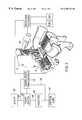
- FIG. 1is a schematic view of a first embodiment of the invention, including a fragmentary view of a preferred turbine design;
- FIG. 2is a schematic view of a second embodiment of the invention which is similar to the embodiment of FIG. 1 but includes circuitry for correcting small disturbances in the power from the primary power supply by making waveform injections into the power transmitted to the critical load.
- FIG. 3is a block diagram of a third embodiment of the invention in which the UPS is on-line in the respect that it supplies power to the critical load when suitable power is available and when the primary power supply has failed.
- a turbine 2has its rotor 4 drivingly connected to the rotor 6 of a rotary electrical machine 8 which is operable, at different times, as a motor and as a generator.
- the shafts of the turbine rotor 4 and the electrical machine rotor 6are coupled together, either directly or indirectly by gearing or other means, so that the electrical machine rotor 6 can drive the turbine rotor 4 , and the turbine rotor can drive the electrical machine rotor.
- Many kinds of motor/generator machines 8can be used but, due to their simplicity and low cost, switched reluctance machines and homopolar inductor alternator machines are preferred.
- the primary power supply represented schematically by box 10 in FIG. 1can be an electric utility, a cogenerator, a small power producer, or a user-operated system; and it can include generation facilities, transmission lines, distribution networks and other components known in the industry.
- a controller 14At the end user's site, there is a controller 14 and a critical load 16 (a computer system, automated manufacturing equipment, etc.) which normally receives electric power from the primary power supply via the distribution line 12 , a local conductor 18 , and a normally closed static switch 20 .
- the controller 14includes power electronics of a type known in the art which can drive the electrical machine at a variable frequency.
- the power electronicscan also receive power from the electrical machine at a variable frequency and convert it to a constant frequency to power the critical load.
- the controller 14has an input line 24 connected to the transmission line, a power line 26 connected to the motor/generator 8 , a control line 27 connected to the static switch 20 , and a control line 28 connected to a combustion system 30 .
- the combustion system 30 and the nozzle 44constitute a fluid supply which is normally inactive but is capable, when activated, to direct a flow of, motive fluid (exhaust gases) against the turbine rotor 4 to rotate the turbine.
- the turbine 2is a Testa turbine of the type disclosed in U.S. Pat. No. 1,061,206, the contents of which are incorporated herein by reference.
- the Tesla turbine 2 shown in FIG. 1has a rotor shaft 34 and a plurality of parallel discs 38 which are rotationally fixed to the shaft and are separated by annular spaces 40 .
- a stationary housing 42encloses the discs.
- a fluid supplyincludes a tangential nozzle 44 for introducing steam, combustion products, or other motive fluids tangentially into the housing 42 , and into the peripheral regions of the spaces 40 between the discs 38 .
- the boundary layer effect of the motive fluid on the surfaces of discs 38rotates the turbine rotor, and the fluid moves in an inward spiral toward the turbine shaft.
- a flywheelmay be mounted on the turbine shaft to provide a greater moment of inertia and angular momentum.
- Combustion productsare the preferred motive fluid for the turbine.
- Such combustion productsare generated by the combustion system 30 which receives and mixes fuel and air from a fuel supply 52 and an air supply 54 .
- the combustion systemignites and burns the fuel, and the resulting exhaust gases are directed by the turbine nozzle 44 against the turbine rotor to drive the turbine.
- the turbine systemmay have conventional components known in the art, including compressors for fuel and air, igniters, separate combustion chambers, cooling systems and various devices such as recuperators that are used to improve turbine efficiency.
- the Tesla turbinehas a number of advantages over traditional bladed turbines, including: simplicity of construction, low cost, high tolerance for particulate contaminants in the air and fuel, reduced maintenance requirements, low audible noise, adaptability for use with multiple fuels, low rotor stress concentrations, high moment of inertia per unit of mass, high moment of inertia per unit of volume, ability to operate at higher tip speeds, ability to store more energy as angular momentum, and reduced thrust bearing requirements when opposed dual exhausts are used.
- the static switch 20When the primary power supply is functioning normally, the static switch 20 is on, and the critical load 16 is powered by the primary power supply through the static switch 20 . Power from the primary power supply also powers the controller 14 and the motor/generator machine 8 which acts as a motor to keep the turbine 2 rotating against windage and bearing losses. The turbine rotor stores kinetic energy as rotational momentum.
- the controller 14When the controller 14 detects a failure in the primary power supply, as when there is a total power loss or when the waveform does not satisfy specifications determined by firmware, software or both, the controller 14 changes the signal in line 27 to turn off the static switch 20 , and the UPS system then operates in a transitional mode in which the momentum of the turbine rotor 4 rotates the rotor of the electrical machine 8 .
- the output of generator 8will have a high frequency which will decrease as the rotor slows down due to dissipation of angular momentum.
- the controller 14includes known power electronic circuitry which converts the generator output to standardized alternating current which has a voltage and a frequency corresponding to those normally provided by the primary power supply to the critical load, typically 60 Hz. When the system is operating in the transitional mode, no energy is supplied to the turbine, and the combustion system 30 is inactive.
- the controller 14initiates the emergency mode of the system by sending a signal via line 28 to activate the combustion system 30 .
- the combustion systemignites a fuel-air mixture to produce exhaust gases in a manner well known in gas turbine technology. These exhaust gases are directed against the rotor by the nozzle 44 , and they act as a motive fluid to rotate the turbine rotor 4 and the coupled electrical machine rotor 6 which continue to generate electric power for the critical load 16 until the fuel supply is exhausted.
- FIG. 2The embodiment of FIG. 2 is similar in most respects to the apparatus shown in FIG. 1, but it has a reactor 60 , usually an inductor, in the local conductor 18 ′ which connects the static switch 20 ′ to the critical load 16 ′.
- the controller 14 ′ in FIG. 2performs the same functions as the controller 14 in FIG. 1 . It makes line interactive corrections when there are small disturbances to the power received from the distribution line 12 ′.
- the controller 14 ′these disturbances, and its power electronics generate a corrective waveform which, as is known in the art, is injected by line 62 into the local conductor 18 ′ on the load side of the reactor 60 .
- Energy for these injectionscan come from the distribution line 12 ′ to the controller 14 ′, from small energy storage elements such as capacitors in the controller 14 ′ and from the angular momentum of the turbine when the electrical machine 8 operates briefly as a generator.
- FIGS. 1 and 2will achieve efficiencies of about 98% while powered by the primary power supply.
- the only lossesare attributable to electrical spinning of the turbine and to dissipation in the static switch and reactor. Air pollution caused by the turbine exhaust is substantially lower than that from a typical diesel engine, so longer legally permissible running times are possible.
- Turbines fired by natural gas or propaneare typically allowed to operate indefinitely.
- FIG. 3is a block diagram of a third embodiment of the invention.
- Thisis an on-line UPS system in which the load 16 ′′ is completely isolated from the waveform properties of the primary power supply 10 ′′ at all times.
- the electrical machineincludes the motor unit 8 m and a generator unit 8 g which are located on opposite sides of a conventional gas turbine 2 ′′.
- the shafts of the motor unit 8 m , gas turbine 2 ′′ and generator unit 8 gare drivingly connected together.
- the motor unithas rotor and stator windings which are independent from the rotor and stator windings of the generator unit.
- the motor and generator unitsare shown in separate housing but, if desired, they can be in a single housing.
- the motor and generator units 8 m , 8 gsimultaneously perform their respective functions as a drive motor and as an electrical generator.
- the motor 8 mis driven by power from the primary power supply 10 ′′ and it keeps the turbine 2 ′′ spinning while the primary power supply is “up”. If switched reluctance or high frequency (greater than 60 Hz) homopolar inductor alternator machines are used, a power electronics drive is used because such machines cannot be directly connected to the primary power supply.
- the output of generator 8 gpowers the critical load 16 ′′ at all times.
- the power electronicscan be omitted from the controller 14 ′′ in situations which do not require precise frequencies and voltages.
- a turbine with a high angular momentummay be driven at a speed which causes the generator output to be at a desired frequency such as 60 Hz. If the primary power supply fails, the rotational momentum of the turbine rotor and any flywheel which may be attached to it will be great enough to maintain a near-60Hz frequency and an acceptable voltage until the turbine combustion system is activated.
- the controller 14 ′′has power conversion electronics which convert the generator's output to clean sinusoidal AC at the normal frequency and voltage of the primary power supply.
- the power converter electronicsare always “warmed up” and driving the full power of the load.
- FIG. 3shows the motor 8 m and generator 8 g as separate entities on opposite sides of the turbine, they can be incorporated into a single machine with separate windings or other arrangement which enable it to operate simultaneously as a motor and generator.
- power from the primary power supply 10can optionally bypass the motor/turbine/generator set and be fed directly to the critical load 16 .
- Such bypass poweris fed from the primary power supply via lines 64 and a bypass switch 66 .
- the motor 8 m in the embodiment of FIG. 3may be a standard inexpensive induction motor driven directly by the primary power supply. If the turbine rotor has a sufficiently high moment of inertia relative to the output torque of motor unit 8 m , the motor unit 8 m may be electrically connected to the primary power source by a variable speed drive (VSD), not shown, which is used when the turbine rotor is accelerated from a dead stop to its normal operational velocity. Once the VSD brings the rotor to speed, a relay connects the motor 8 m directly to the primary power supply for efficient full-power operation. This relay is open during primary power supply outages.
- VSDvariable speed drive
- the on-line configuration shown in FIG. 3is believed by some users to achieve the ultimate in power quality and reliability. However, it is more expensive than the embodiments shown in FIGS. 1 and 2 because it requires two rotating electrical machines or one larger machine capable of continuous simultaneous operation as a motor and as a generator at the rated power. The efficiency of this configuration is typically 90 to 94%. This is lower than the efficiency of the embodiments of FIGS. 1 and 2 because, in the FIG. 3 embodiments, the two rotating electrical machines operate continuously at their rated power.
Landscapes
- Engineering & Computer Science (AREA)
- Power Engineering (AREA)
- Business, Economics & Management (AREA)
- Emergency Management (AREA)
- Stand-By Power Supply Arrangements (AREA)
- Control Of Eletrric Generators (AREA)
Abstract
Description
Claims (50)
Priority Applications (5)
| Application Number | Priority Date | Filing Date | Title |
|---|---|---|---|
| US09/318,728US6255743B1 (en) | 1999-05-26 | 1999-05-26 | Method and apparatus for providing an uninterruptible supply of electric power to a critical load |
| EP00936110AEP1190477A1 (en) | 1999-05-26 | 2000-05-19 | Method and apparatus for providing an uninterruptible supply of electric power to a critical load |
| AU51471/00AAU5147100A (en) | 1999-05-26 | 2000-05-19 | Method and apparatus for providing an uninterruptible supply of electric power to a critical load |
| PCT/US2000/013867WO2000074203A1 (en) | 1999-05-26 | 2000-05-19 | Method and apparatus for providing an uninterruptible supply of electric power to a critical load |
| US09/595,101US6512305B1 (en) | 1999-05-26 | 2000-06-16 | Method and apparatus having a turbine working in different modes for providing an uninterruptible supply of electric power to a critical load |
Applications Claiming Priority (1)
| Application Number | Priority Date | Filing Date | Title |
|---|---|---|---|
| US09/318,728US6255743B1 (en) | 1999-05-26 | 1999-05-26 | Method and apparatus for providing an uninterruptible supply of electric power to a critical load |
Related Child Applications (1)
| Application Number | Title | Priority Date | Filing Date |
|---|---|---|---|
| US09/595,101Continuation-In-PartUS6512305B1 (en) | 1999-05-26 | 2000-06-16 | Method and apparatus having a turbine working in different modes for providing an uninterruptible supply of electric power to a critical load |
Publications (1)
| Publication Number | Publication Date |
|---|---|
| US6255743B1true US6255743B1 (en) | 2001-07-03 |
Family
ID=23239368
Family Applications (1)
| Application Number | Title | Priority Date | Filing Date |
|---|---|---|---|
| US09/318,728Expired - LifetimeUS6255743B1 (en) | 1999-05-26 | 1999-05-26 | Method and apparatus for providing an uninterruptible supply of electric power to a critical load |
Country Status (4)
| Country | Link |
|---|---|
| US (1) | US6255743B1 (en) |
| EP (1) | EP1190477A1 (en) |
| AU (1) | AU5147100A (en) |
| WO (1) | WO2000074203A1 (en) |
Cited By (35)
| Publication number | Priority date | Publication date | Assignee | Title |
|---|---|---|---|---|
| WO2002044555A1 (en)* | 2000-11-28 | 2002-06-06 | Ormat Technologies Inc. | Flywheel based ups apparatus and method for using same |
| US6408627B1 (en)* | 2001-05-21 | 2002-06-25 | Active Power, Inc. | Integrated continuous power system assemblies |
| US6463738B1 (en)* | 2001-05-21 | 2002-10-15 | Active Power, Inc. | Method and apparatus for providing a continuous supply of electric power |
| US6507128B2 (en)* | 2001-05-23 | 2003-01-14 | General Electric Company | Low-energy storage fast-start uninterruptible power supply system and method |
| WO2003085254A1 (en)* | 2002-04-04 | 2003-10-16 | Illusion Technologies, Llc | Miniature/micro scale power generation system |
| US20040070518A1 (en)* | 2002-10-04 | 2004-04-15 | Carroll Whittle | Emergency vehicular traffic signal control |
| US20040148934A1 (en)* | 2003-02-05 | 2004-08-05 | Pinkerton Joseph F. | Systems and methods for providing backup energy to a load |
| US20060059936A1 (en)* | 2004-09-17 | 2006-03-23 | Radke Robert E | Systems and methods for providing cooling in compressed air storage power supply systems |
| US20060059937A1 (en)* | 2004-09-17 | 2006-03-23 | Perkins David E | Systems and methods for providing cooling in compressed air storage power supply systems |
| US20060060246A1 (en)* | 2004-09-17 | 2006-03-23 | Schuetze Karl T | Systems and methods for controlling pressure of fluids |
| US20060076426A1 (en)* | 2004-09-17 | 2006-04-13 | Schuetze Karl T | Systems and methods for controlling temperature and pressure of fluids |
| US20060097578A1 (en)* | 2004-11-10 | 2006-05-11 | Baldwin Technologies, Inc. | High reliability DC power distribution system |
| US20070005195A1 (en)* | 2005-01-10 | 2007-01-04 | Nicholas Pasquale | Distributed energy storage for reducing power demand |
| US20080048456A1 (en)* | 2006-08-23 | 2008-02-28 | Northern Power Systems, Inc. | Modular microturbine system |
| US7400052B1 (en) | 2006-11-29 | 2008-07-15 | Active Power, Inc. | Transient energy systems and methods for use of the same |
| US20080178586A1 (en)* | 2007-01-29 | 2008-07-31 | Wabtec Holding Corp. | Air turbine generator |
| US7425807B1 (en) | 2006-11-29 | 2008-09-16 | Active Power, Inc. | Transient energy systems and methods for use of the same |
| US20090058098A1 (en)* | 2007-08-13 | 2009-03-05 | Michael Patrick Flynn | Backup generators |
| US20090230774A1 (en)* | 2008-03-17 | 2009-09-17 | Robert Bosch Gmbh | Extended controller keep alive system and method |
| US7642664B1 (en) | 2006-11-29 | 2010-01-05 | Active Power, Inc. | Transient energy systems and methods for use of the same |
| US7710081B2 (en) | 2006-10-27 | 2010-05-04 | Direct Drive Systems, Inc. | Electromechanical energy conversion systems |
| US7750518B1 (en) | 2006-11-29 | 2010-07-06 | Active Power, Inc. | Transient energy systems and methods for use of the same |
| US7918091B1 (en) | 2006-09-20 | 2011-04-05 | Active Power, Inc. | Systems and methods for controlling humidity |
| US8040007B2 (en) | 2008-07-28 | 2011-10-18 | Direct Drive Systems, Inc. | Rotor for electric machine having a sleeve with segmented layers |
| US8106563B2 (en) | 2006-06-08 | 2012-01-31 | Exro Technologies Inc. | Polyphasic multi-coil electric device |
| US8212445B2 (en) | 2004-08-12 | 2012-07-03 | Exro Technologies Inc. | Polyphasic multi-coil electric device |
| US20130049473A1 (en)* | 2011-08-23 | 2013-02-28 | International Business Machines Corporation | Fluid-driven flywheel uninterruptible power supply |
| US20140311158A1 (en)* | 2013-04-18 | 2014-10-23 | Arkadiusz Brzeski | Heat and power plant with a waste gasification system |
| US9504188B1 (en) | 2015-11-30 | 2016-11-22 | International Business Machines Corporation | Air-moving assembly with auxiliary turbine drive |
| US11081996B2 (en) | 2017-05-23 | 2021-08-03 | Dpm Technologies Inc. | Variable coil configuration system control, apparatus and method |
| US20220117120A1 (en)* | 2020-10-08 | 2022-04-14 | Caeli, LLC | Uninterruptible power and cooling for critical power applications |
| US11708005B2 (en) | 2021-05-04 | 2023-07-25 | Exro Technologies Inc. | Systems and methods for individual control of a plurality of battery cells |
| US11722026B2 (en) | 2019-04-23 | 2023-08-08 | Dpm Technologies Inc. | Fault tolerant rotating electric machine |
| US11967913B2 (en) | 2021-05-13 | 2024-04-23 | Exro Technologies Inc. | Method and apparatus to drive coils of a multiphase electric machine |
| US12176836B2 (en) | 2018-09-05 | 2024-12-24 | Dpm Technologies Inc. | Systems and methods for intelligent energy storage and provisioning using an energy storage control system |
Families Citing this family (9)
| Publication number | Priority date | Publication date | Assignee | Title |
|---|---|---|---|---|
| US20090152951A1 (en)* | 2007-12-18 | 2009-06-18 | Caterpillar Inc. | Electric system for providing uninterruptible power |
| GB0905343D0 (en) | 2009-03-27 | 2009-05-13 | Ricardo Uk Ltd | A flywheel |
| GB0905345D0 (en) | 2009-03-27 | 2009-05-13 | Ricardo Uk Ltd | A flywheel |
| GB0905344D0 (en) | 2009-03-27 | 2009-05-13 | Ricardo Uk Ltd | A flywheel |
| KR20120107468A (en)* | 2009-10-20 | 2012-10-02 | 리카도 유케이 리미티드 | Energy control |
| GB201019473D0 (en) | 2010-11-17 | 2010-12-29 | Ricardo Uk Ltd | An improved coupler |
| GB201106768D0 (en) | 2011-04-20 | 2011-06-01 | Ricardo Uk Ltd | An energy storage system |
| GB2494122A (en)* | 2011-08-29 | 2013-03-06 | Matthew George Salisbury | Boundary layer turbine with heat recovery |
| JP5614440B2 (en) | 2011-10-26 | 2014-10-29 | 日立化成株式会社 | Circuit component and manufacturing method thereof |
Citations (18)
| Publication number | Priority date | Publication date | Assignee | Title |
|---|---|---|---|---|
| US4059770A (en) | 1974-10-15 | 1977-11-22 | The Garrett Corporation | Uninterruptible electric power supply |
| US4224797A (en)* | 1977-05-09 | 1980-09-30 | Kelly Donald A | Variable speed, condensing steam turbine and power system |
| US4295334A (en)* | 1979-12-03 | 1981-10-20 | Johnson Richard N | Parametric energy converter |
| US4402647A (en)* | 1979-12-06 | 1983-09-06 | Effenberger Udo E | Viscosity impeller |
| US4652207A (en)* | 1985-07-22 | 1987-03-24 | Brown Charles W | Vaneless centrifugal pump |
| US4655679A (en)* | 1983-05-25 | 1987-04-07 | Ltv Aerospace And Defense Company | Power translation device |
| US4686375A (en)* | 1986-03-05 | 1987-08-11 | Power Group International Corp. | Uninterruptible power supply cogeneration system |
| US4754607A (en)* | 1986-12-12 | 1988-07-05 | Allied-Signal Inc. | Power generating system |
| US4935650A (en) | 1989-09-25 | 1990-06-19 | Westinghouse Electric Corp. | Magnetohydrodynamic turbomachine construction for electric motors and generators |
| US5434454A (en)* | 1991-04-04 | 1995-07-18 | Farkas; Otto | Transient-free synchronous electrical power machine |
| US5536976A (en)* | 1994-03-03 | 1996-07-16 | Gas Research Institute | Multiple service load solid state switching for controlled cogeneration system |
| US5553454A (en) | 1995-03-20 | 1996-09-10 | Mortner; Sol E. | Compressed air engine system and method for generating electrical energy from the controlled release of compressed air |
| EP0734113A2 (en) | 1995-03-23 | 1996-09-25 | Hitachi, Ltd. | Power generation plant and control apparatus therefor |
| JPH10257696A (en) | 1997-03-14 | 1998-09-25 | Shinko Electric Co Ltd | Emergency power supply equipment |
| US6031294A (en) | 1998-01-05 | 2000-02-29 | Capstone Turbine Corporation | Turbogenerator/motor controller with ancillary energy storage/discharge |
| US6032459A (en)* | 1998-06-15 | 2000-03-07 | Alliedsignal, Inc. | Turbine exhaust cooling in a microturbine power generating system |
| US6064122A (en) | 1998-11-05 | 2000-05-16 | Alliedsignal Power Systems Inc. | Microturbine power of generating system including a battery source for supplying startup power |
| US6093975A (en) | 1998-10-27 | 2000-07-25 | Capstone Turbine Corporation | Turbogenerator/motor control with synchronous condenser |
Family Cites Families (1)
| Publication number | Priority date | Publication date | Assignee | Title |
|---|---|---|---|---|
| DE19833420C1 (en)* | 1998-07-24 | 1999-10-28 | Piller Gmbh | Emergency current supply method using electromechanical energy converter e.g. for submarine |
- 1999
- 1999-05-26USUS09/318,728patent/US6255743B1/ennot_activeExpired - Lifetime
- 2000
- 2000-05-19WOPCT/US2000/013867patent/WO2000074203A1/enactiveApplication Filing
- 2000-05-19EPEP00936110Apatent/EP1190477A1/ennot_activeWithdrawn
- 2000-05-19AUAU51471/00Apatent/AU5147100A/ennot_activeAbandoned
Patent Citations (18)
| Publication number | Priority date | Publication date | Assignee | Title |
|---|---|---|---|---|
| US4059770A (en) | 1974-10-15 | 1977-11-22 | The Garrett Corporation | Uninterruptible electric power supply |
| US4224797A (en)* | 1977-05-09 | 1980-09-30 | Kelly Donald A | Variable speed, condensing steam turbine and power system |
| US4295334A (en)* | 1979-12-03 | 1981-10-20 | Johnson Richard N | Parametric energy converter |
| US4402647A (en)* | 1979-12-06 | 1983-09-06 | Effenberger Udo E | Viscosity impeller |
| US4655679A (en)* | 1983-05-25 | 1987-04-07 | Ltv Aerospace And Defense Company | Power translation device |
| US4652207A (en)* | 1985-07-22 | 1987-03-24 | Brown Charles W | Vaneless centrifugal pump |
| US4686375A (en)* | 1986-03-05 | 1987-08-11 | Power Group International Corp. | Uninterruptible power supply cogeneration system |
| US4754607A (en)* | 1986-12-12 | 1988-07-05 | Allied-Signal Inc. | Power generating system |
| US4935650A (en) | 1989-09-25 | 1990-06-19 | Westinghouse Electric Corp. | Magnetohydrodynamic turbomachine construction for electric motors and generators |
| US5434454A (en)* | 1991-04-04 | 1995-07-18 | Farkas; Otto | Transient-free synchronous electrical power machine |
| US5536976A (en)* | 1994-03-03 | 1996-07-16 | Gas Research Institute | Multiple service load solid state switching for controlled cogeneration system |
| US5553454A (en) | 1995-03-20 | 1996-09-10 | Mortner; Sol E. | Compressed air engine system and method for generating electrical energy from the controlled release of compressed air |
| EP0734113A2 (en) | 1995-03-23 | 1996-09-25 | Hitachi, Ltd. | Power generation plant and control apparatus therefor |
| JPH10257696A (en) | 1997-03-14 | 1998-09-25 | Shinko Electric Co Ltd | Emergency power supply equipment |
| US6031294A (en) | 1998-01-05 | 2000-02-29 | Capstone Turbine Corporation | Turbogenerator/motor controller with ancillary energy storage/discharge |
| US6032459A (en)* | 1998-06-15 | 2000-03-07 | Alliedsignal, Inc. | Turbine exhaust cooling in a microturbine power generating system |
| US6093975A (en) | 1998-10-27 | 2000-07-25 | Capstone Turbine Corporation | Turbogenerator/motor control with synchronous condenser |
| US6064122A (en) | 1998-11-05 | 2000-05-16 | Alliedsignal Power Systems Inc. | Microturbine power of generating system including a battery source for supplying startup power |
Cited By (60)
| Publication number | Priority date | Publication date | Assignee | Title |
|---|---|---|---|---|
| WO2002044555A1 (en)* | 2000-11-28 | 2002-06-06 | Ormat Technologies Inc. | Flywheel based ups apparatus and method for using same |
| US6408627B1 (en)* | 2001-05-21 | 2002-06-25 | Active Power, Inc. | Integrated continuous power system assemblies |
| US6463738B1 (en)* | 2001-05-21 | 2002-10-15 | Active Power, Inc. | Method and apparatus for providing a continuous supply of electric power |
| US7129593B2 (en) | 2001-05-23 | 2006-10-31 | General Electric Company | Low-energy storage fast-start uninterruptible power supply method |
| US6507128B2 (en)* | 2001-05-23 | 2003-01-14 | General Electric Company | Low-energy storage fast-start uninterruptible power supply system and method |
| WO2003085254A1 (en)* | 2002-04-04 | 2003-10-16 | Illusion Technologies, Llc | Miniature/micro scale power generation system |
| US20050180845A1 (en)* | 2002-04-04 | 2005-08-18 | Vreeke Mark S. | Miniature/micro-scale power generation system |
| US20040070518A1 (en)* | 2002-10-04 | 2004-04-15 | Carroll Whittle | Emergency vehicular traffic signal control |
| US7127895B2 (en)* | 2003-02-05 | 2006-10-31 | Active Power, Inc. | Systems and methods for providing backup energy to a load |
| US20070022755A1 (en)* | 2003-02-05 | 2007-02-01 | Active Power, Inc. | Systems and methods for providing backup energy to a load |
| US20040148934A1 (en)* | 2003-02-05 | 2004-08-05 | Pinkerton Joseph F. | Systems and methods for providing backup energy to a load |
| US7681395B2 (en) | 2003-02-05 | 2010-03-23 | Joseph F Pinkerton | Systems and methods for providing backup energy to a load |
| US8212445B2 (en) | 2004-08-12 | 2012-07-03 | Exro Technologies Inc. | Polyphasic multi-coil electric device |
| US9685827B2 (en) | 2004-08-12 | 2017-06-20 | Exro Technologies Inc. | Polyphasic multi-coil electric device |
| US8614529B2 (en) | 2004-08-12 | 2013-12-24 | Exro Technologies, Inc. | Polyphasic multi-coil electric device |
| US7314059B2 (en) | 2004-09-17 | 2008-01-01 | Active Power, Inc. | Systems and methods for controlling pressure of fluids |
| US20060059936A1 (en)* | 2004-09-17 | 2006-03-23 | Radke Robert E | Systems and methods for providing cooling in compressed air storage power supply systems |
| US20060060246A1 (en)* | 2004-09-17 | 2006-03-23 | Schuetze Karl T | Systems and methods for controlling pressure of fluids |
| US20060076426A1 (en)* | 2004-09-17 | 2006-04-13 | Schuetze Karl T | Systems and methods for controlling temperature and pressure of fluids |
| US20060059937A1 (en)* | 2004-09-17 | 2006-03-23 | Perkins David E | Systems and methods for providing cooling in compressed air storage power supply systems |
| US8333330B2 (en) | 2004-09-17 | 2012-12-18 | Active Power, Inc. | Systems and methods for controlling temperature and pressure of fluids |
| US7492057B2 (en) | 2004-11-10 | 2009-02-17 | Baldwin Mark H | High reliability DC power distribution system |
| US20060097578A1 (en)* | 2004-11-10 | 2006-05-11 | Baldwin Technologies, Inc. | High reliability DC power distribution system |
| US20070005195A1 (en)* | 2005-01-10 | 2007-01-04 | Nicholas Pasquale | Distributed energy storage for reducing power demand |
| US8106563B2 (en) | 2006-06-08 | 2012-01-31 | Exro Technologies Inc. | Polyphasic multi-coil electric device |
| US9584056B2 (en) | 2006-06-08 | 2017-02-28 | Exro Technologies Inc. | Polyphasic multi-coil generator |
| US20080048456A1 (en)* | 2006-08-23 | 2008-02-28 | Northern Power Systems, Inc. | Modular microturbine system |
| US7918091B1 (en) | 2006-09-20 | 2011-04-05 | Active Power, Inc. | Systems and methods for controlling humidity |
| US7960948B2 (en) | 2006-10-27 | 2011-06-14 | Direct Drive Systems, Inc. | Electromechanical energy conversion systems |
| US7710081B2 (en) | 2006-10-27 | 2010-05-04 | Direct Drive Systems, Inc. | Electromechanical energy conversion systems |
| US7750518B1 (en) | 2006-11-29 | 2010-07-06 | Active Power, Inc. | Transient energy systems and methods for use of the same |
| US20100171366A1 (en)* | 2006-11-29 | 2010-07-08 | Active Power, Inc. | Transient energy systems and methods for use of the same |
| US7400052B1 (en) | 2006-11-29 | 2008-07-15 | Active Power, Inc. | Transient energy systems and methods for use of the same |
| US7642664B1 (en) | 2006-11-29 | 2010-01-05 | Active Power, Inc. | Transient energy systems and methods for use of the same |
| US7425807B1 (en) | 2006-11-29 | 2008-09-16 | Active Power, Inc. | Transient energy systems and methods for use of the same |
| US20080178586A1 (en)* | 2007-01-29 | 2008-07-31 | Wabtec Holding Corp. | Air turbine generator |
| US7468564B2 (en)* | 2007-01-29 | 2008-12-23 | Wabtec Holding Corp. | Air turbine generator |
| US20090058098A1 (en)* | 2007-08-13 | 2009-03-05 | Michael Patrick Flynn | Backup generators |
| US20090230774A1 (en)* | 2008-03-17 | 2009-09-17 | Robert Bosch Gmbh | Extended controller keep alive system and method |
| US7961449B2 (en)* | 2008-03-17 | 2011-06-14 | Robert Bosch Gmbh | Extended controller keep alive system and method |
| US8179009B2 (en) | 2008-07-28 | 2012-05-15 | Direct Drive Systems, Inc. | Rotor for an electric machine |
| US8040007B2 (en) | 2008-07-28 | 2011-10-18 | Direct Drive Systems, Inc. | Rotor for electric machine having a sleeve with segmented layers |
| US8310123B2 (en) | 2008-07-28 | 2012-11-13 | Direct Drive Systems, Inc. | Wrapped rotor sleeve for an electric machine |
| US8183734B2 (en) | 2008-07-28 | 2012-05-22 | Direct Drive Systems, Inc. | Hybrid winding configuration of an electric machine |
| US8350432B2 (en) | 2008-07-28 | 2013-01-08 | Direct Drive Systems, Inc. | Electric machine |
| US8415854B2 (en) | 2008-07-28 | 2013-04-09 | Direct Drive Systems, Inc. | Stator for an electric machine |
| US8421297B2 (en) | 2008-07-28 | 2013-04-16 | Direct Drive Systems, Inc. | Stator wedge for an electric machine |
| US8247938B2 (en) | 2008-07-28 | 2012-08-21 | Direct Drive Systems, Inc. | Rotor for electric machine having a sleeve with segmented layers |
| US8253298B2 (en) | 2008-07-28 | 2012-08-28 | Direct Drive Systems, Inc. | Slot configuration of an electric machine |
| US8237320B2 (en) | 2008-07-28 | 2012-08-07 | Direct Drive Systems, Inc. | Thermally matched composite sleeve |
| US20130049473A1 (en)* | 2011-08-23 | 2013-02-28 | International Business Machines Corporation | Fluid-driven flywheel uninterruptible power supply |
| US20140311158A1 (en)* | 2013-04-18 | 2014-10-23 | Arkadiusz Brzeski | Heat and power plant with a waste gasification system |
| US9504188B1 (en) | 2015-11-30 | 2016-11-22 | International Business Machines Corporation | Air-moving assembly with auxiliary turbine drive |
| US11081996B2 (en) | 2017-05-23 | 2021-08-03 | Dpm Technologies Inc. | Variable coil configuration system control, apparatus and method |
| US12176836B2 (en) | 2018-09-05 | 2024-12-24 | Dpm Technologies Inc. | Systems and methods for intelligent energy storage and provisioning using an energy storage control system |
| US11722026B2 (en) | 2019-04-23 | 2023-08-08 | Dpm Technologies Inc. | Fault tolerant rotating electric machine |
| US20220117120A1 (en)* | 2020-10-08 | 2022-04-14 | Caeli, LLC | Uninterruptible power and cooling for critical power applications |
| US12193195B2 (en)* | 2020-10-08 | 2025-01-07 | Caeli, LLC | Uninterruptible power and cooling for critical power applications |
| US11708005B2 (en) | 2021-05-04 | 2023-07-25 | Exro Technologies Inc. | Systems and methods for individual control of a plurality of battery cells |
| US11967913B2 (en) | 2021-05-13 | 2024-04-23 | Exro Technologies Inc. | Method and apparatus to drive coils of a multiphase electric machine |
Also Published As
| Publication number | Publication date |
|---|---|
| AU5147100A (en) | 2000-12-18 |
| WO2000074203A1 (en) | 2000-12-07 |
| EP1190477A1 (en) | 2002-03-27 |
Similar Documents
| Publication | Publication Date | Title |
|---|---|---|
| US6255743B1 (en) | Method and apparatus for providing an uninterruptible supply of electric power to a critical load | |
| US6512305B1 (en) | Method and apparatus having a turbine working in different modes for providing an uninterruptible supply of electric power to a critical load | |
| US6194794B1 (en) | Integrated reciprocating engine generator set and turbogenerator system and method | |
| JP6625161B2 (en) | DC coupled power electronics system for fuel cell power system | |
| JP3738037B2 (en) | Independent electrical system including asynchronous machine and inverter / rectifier with motive force | |
| US6175210B1 (en) | Prime mover for operating an electric motor | |
| KR100788322B1 (en) | A microturbine power generating system and a method thereof | |
| US7239034B2 (en) | Engine driven power inverter system with cogeneration | |
| US6713892B2 (en) | Automatic turbogenerator restarting system | |
| JP2018198525A (en) | Ac coupling type power electronics system for fuel cell power system | |
| CN102754298B (en) | Power supply device and method | |
| US20020167234A1 (en) | Standby power system | |
| WO1999032762A1 (en) | An uninterruptible microturbine power generating system | |
| WO2014193238A1 (en) | Fault tolerant power supply for active magnetic bearing | |
| US8436488B2 (en) | Semi-direct variable speed drive with N+1 power availability | |
| US20060022524A1 (en) | Distributed power generation, conversion, and storage system | |
| WO2002044555A1 (en) | Flywheel based ups apparatus and method for using same | |
| US8198743B2 (en) | Multi-stage controlled frequency generator for direct-drive wind power | |
| JPH04241704A (en) | Rotary fluid machine | |
| US6777823B1 (en) | Integrated continuous power system assemblies having multiple nozzle block segments | |
| KR100314948B1 (en) | Microturbine power generating system | |
| CN220585994U (en) | Grid-connected power generation system | |
| CN211008857U (en) | Starting and running stable aero-engine | |
| JP2004019476A (en) | Gas turbine system | |
| CN1051466A (en) | Uninterrupted power supply(ups) with gas turbine as power |
Legal Events
| Date | Code | Title | Description |
|---|---|---|---|
| AS | Assignment | Owner name:ACTIVE POWER, INC., (A CORPORATION OF TEXAS), TEXA Free format text:ASSIGNMENT OF ASSIGNORS INTEREST;ASSIGNORS:PINKERTON, JOSEPH F.;CLIFTON, DAVID B.;REEL/FRAME:010002/0547 Effective date:19990526 | |
| STCF | Information on status: patent grant | Free format text:PATENTED CASE | |
| CC | Certificate of correction | ||
| FPAY | Fee payment | Year of fee payment:4 | |
| AS | Assignment | Owner name:SILICON VALLEY BANK, CALIFORNIA Free format text:SECURITY AGREEMENT;ASSIGNOR:ACTIVE POWER, INC.;REEL/FRAME:019920/0738 Effective date:20071005 | |
| AS | Assignment | Owner name:SILICON VALLEY BANK, CALIFORNIA Free format text:SECURITY AGREEMENT;ASSIGNOR:ACTIVE POWER, INC.;REEL/FRAME:020018/0413 Effective date:20071005 | |
| REMI | Maintenance fee reminder mailed | ||
| FPAY | Fee payment | Year of fee payment:8 | |
| SULP | Surcharge for late payment | Year of fee payment:7 | |
| FPAY | Fee payment | Year of fee payment:12 | |
| SULP | Surcharge for late payment | Year of fee payment:11 | |
| AS | Assignment | Owner name:PILLER USA, INC., NEW YORK Free format text:ASSIGNMENT OF ASSIGNORS INTEREST;ASSIGNOR:ACTIVE POWER, INC.;REEL/FRAME:041278/0281 Effective date:20161119 | |
| AS | Assignment | Owner name:P10 INDUSTRIES, LNC., TEXAS Free format text:ASSIGNMENT OF ASSIGNORS INTEREST;ASSIGNOR:PILLER USA, INC.;REEL/FRAME:042875/0079 Effective date:20161119 | |
| AS | Assignment | Owner name:P10 INDUSTRIES, INC., TEXAS Free format text:CORRECTIVE ASSIGNMENT TO CORRECT THE ASSIGNEE NAME ON THE COVER SHEET TO P10 INDUSTRIES, INC. PREVIOUSLY RECORDED ON REEL 042875 FRAME 0079. ASSIGNOR(S) HEREBY CONFIRMS THE ASSIGNMENT;ASSIGNOR:PILLER USA, INC.;REEL/FRAME:054427/0880 Effective date:20161119 |