US6254535B1 - Ball and socket coronary stabilizer - Google Patents
Ball and socket coronary stabilizerDownload PDFInfo
- Publication number
- US6254535B1 US6254535B1US08/792,151US79215197AUS6254535B1US 6254535 B1US6254535 B1US 6254535B1US 79215197 AUS79215197 AUS 79215197AUS 6254535 B1US6254535 B1US 6254535B1
- Authority
- US
- United States
- Prior art keywords
- ball
- socket
- handle
- shaft
- bore
- Prior art date
- Legal status (The legal status is an assumption and is not a legal conclusion. Google has not performed a legal analysis and makes no representation as to the accuracy of the status listed.)
- Expired - Lifetime
Links
Images


Classifications
- A—HUMAN NECESSITIES
- A61—MEDICAL OR VETERINARY SCIENCE; HYGIENE
- A61B—DIAGNOSIS; SURGERY; IDENTIFICATION
- A61B17/00—Surgical instruments, devices or methods
- A61B17/02—Surgical instruments, devices or methods for holding wounds open, e.g. retractors; Tractors
- A61B17/0206—Surgical instruments, devices or methods for holding wounds open, e.g. retractors; Tractors with antagonistic arms as supports for retractor elements
- A—HUMAN NECESSITIES
- A61—MEDICAL OR VETERINARY SCIENCE; HYGIENE
- A61B—DIAGNOSIS; SURGERY; IDENTIFICATION
- A61B17/00—Surgical instruments, devices or methods
- A61B17/00234—Surgical instruments, devices or methods for minimally invasive surgery
- A61B2017/00238—Type of minimally invasive operation
- A61B2017/00243—Type of minimally invasive operation cardiac
- A—HUMAN NECESSITIES
- A61—MEDICAL OR VETERINARY SCIENCE; HYGIENE
- A61B—DIAGNOSIS; SURGERY; IDENTIFICATION
- A61B17/00—Surgical instruments, devices or methods
- A61B17/02—Surgical instruments, devices or methods for holding wounds open, e.g. retractors; Tractors
- A61B2017/0237—Surgical instruments, devices or methods for holding wounds open, e.g. retractors; Tractors for heart surgery
- A61B2017/0243—Surgical instruments, devices or methods for holding wounds open, e.g. retractors; Tractors for heart surgery for immobilizing local areas of the heart, e.g. while it beats
Definitions
- This inventionrelates to an apparatus for stabilizing a predetermined area of the body during surgical intervention, which better enables a surgeon to perform a surgical procedure at the surgical site.
- the inventionrelates to an apparatus for stabilizing a predetermined area of the heart for performing minimally invasive coronary artery bypass grafting at the surgical site, in which the apparatus is adapted to be connected to a rib retractor, has a rotatable and pivotal joint between the handle and stabilizing device, and has a means for easily switching among different sized stabilizing devices.
- Atherosclerosis or coronary artery diseaseis among the most common and serious health problems confronting the medical profession.
- many different approaches at therapyhave been utilized. Surgical correction of occluded or stenosed coronary arteries via bypass grafting through conventional approaches, such as the sternotomy, are probably still the most common procedure performed today, especially where multiple bypass grafts are needed.
- PTCApercutaneous transluminal angioplasty
- the transluminal approachis a minimally invasive technique which subjects the patient to less trauma and less recovery time, especially when compared to bypass grafts which utilize homologous tissue, such as saphenous vein grafts. Often the patient suffers complications at the graft donor site which are worse than the sternotomy and anastomosis.
- PTCA proceduresare often successful, complications such as restenosis or thrombosis and embolism can occur.
- Intravascular stentsare sometimes deployed at the PTCA site to lessen the occurrence of restenosis.
- restenosed vesselsoften require surgical intervention for correction.
- physicianshave recently turned to minimally invasive surgical approaches to the heart, such as intercostal and endoscopic access to the surgical site.
- utilization of alternative graft vessels, such as the internal mammary artery (IMA)have also greatly reduced the trauma to the patient and increased the efficacy of surgical therapy.
- IMAinternal mammary artery
- the above problems of the prior artare overcome by the present invention, which provides an apparatus for stabilizing a predetermined area on a heart or other organ of a patient to enable a surgical procedure to be performed.
- the apparatus of the present inventioncomprises a bifurcated member having two prongs, an elongated handle segment, and a means for pivotally connecting the handle segment to the bifurcated member.
- Each prong of the bifurcated memberalso known as a tine assembly, has a first section and a second section. The first section is adjacent the handle segment and terminates in the second section. The second section engages the heart or other organ on which the surgical procedure occurs.
- the present inventionalso encompasses a means for movably mounting the handle segment to a rib retractor or other surgical device.
- the mounting meanswhich is preferably a swivel head, holds the bifurcated member at the predetermined site, thus alleviating the requirement that a person hold the handle segment.
- a further aspect of the present inventionis that it includes a means for rotatably and pivotally connecting the bifurcated member to the handle segment.
- a ball and socket designis used.
- the present inventioncomprises a means for locking the bifurcated member in a desired position relative to the handle segment when the bifurcated member is disposed on the heart of a patient. The surgeon can tighten the ball and socket to frictionally hold the assembly using a tightener located at the upper end of the handle segment, which is advantageous during a surgical procedure where space within the surgical site is limited.
- the second section of the bifurcated memberengages the heart, it is desired that the second section further comprises a means for stabilizing it from sliding on the heart. Stabilizing the apparatus on the heart is an important consideration during the surgical procedure.
- the present inventioncan encompass many different stabilizing means, including, for example, a DeBakey serrated pattern, a textured portion on at least a portion of one second section, an insert disposed on the second section having a plurality of teeth, an insert having a plurality of flexible hooks, an insert having a plurality of bristles, or even a flexible covering disposed over at least a portion of the second section.
- the flexible coveringcan be a cloth, such as cotton, or a tubular member formed from a material such as silicon.
- the apparatus of the present inventioncan be used in surgical procedures other than heart surgery, including, for example, soft tissue procedures such as vascular thrombosis repair, intestinal resection and anastomosis and other intra-abdominal procedures, and the like.
- Another object of the inventionis to provide an apparatus for stabilization of an area of the beating heart adjacent to a coronary artery for performing coronary artery bypass grafting.
- Yet another objective of the present inventionis to provide an apparatus in which the bifurcated member can both rotate and pivot relative to the handle segment to ensure the maximum adaptability for work within the surgical site.
- An associated objectiveis to use an apparatus in which the bifurcated member can be easily exchanged with another bifurcated member of a different size when necessary.
- a further object of the inventionis to provide an apparatus as above that is adapted for pivotal attachment to a device that provides access to the surgical site, such as a rib spreader or other retractor.
- FIG. 1is a side view of one embodiment of the present invention showing the stabilizer mounted to a rib retractor in which the bifurcated member is pivotally connected to the handle segment.
- FIG. 2is a top plan view of FIG. 1 .
- FIG. 3is a side view of the stabilizer shown in FIG. 1 .
- FIG. 4is a bottom plan view of FIG. 3 .
- FIG. 5is a side view, partially in cross section, of a first, preferred embodiment of the stabilizer having a ball and socket pivotal and rotatable connecting means in which the bifurcated member is removable.
- FIGS. 5A-5Dare views of FIG. 5 showing the bifurcated member being attached to the handle segment and then being locked in the desired position.
- FIG. 5Ais a front view showing the withdrawn position, in which the bifurcated member is spaced apart from the handle segment.
- FIG. 5Bis a side view showing the ball being inserted into a section of the bore within the handle segment.
- FIG. 5Cis a front view showing the occupied position, in which the ball is placed within the bore.
- FIG. 5Dis a front view showing the engaged position, in which the socket engages the ball.
- FIG. 6is a side cross-sectional view of a second alternative embodiment of the stabilizer having a ball and socket pivotal and rotatable connecting means in which the bifurcated member is removable.
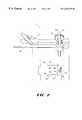
- FIG. 7is a perspective view of a third alternative embodiment of the stabilizer of the present invention having a ball and socket pivotal and rotatable connecting means.
- FIG. 8is a bottom perspective view of a portion of the bifurcated member of the present invention showing the textured surface on the second section of the prongs.
- the present inventionencompasses an apparatus 10 for stabilizing a predetermined area on a heart of a patient to enable a surgical procedure to be performed.
- the apparatus 10or stabilizer, comprises a bifurcated member 30 that is pivotally connected to an elongated handle segment 50 .
- the handle segment 50is preferably movably mounted to a rib spreader 20 or other similar equipment that remains stationary positioned on or adjacent to the patient during a surgical procedure.
- the present inventionis ideal for use in heart surgery, in either conventional open heart surgery or by minimally invasive surgery, e.g., minimally invasive coronary artery bypass grafting.
- minimally invasive surgeryaccess to the heart may be achieved through the ribs of the patient using a rib spreader 20 , as shown in FIGS. 1 and 2.
- the surgeonswill access the heart via the fourth intercostal space located between the third and fourth ribs, but this may be changed based on the individual patient's anatomy. Since, for the above reasons, this procedure is sometimes performed on a beating heart, it is advantageous to stabilize the heart in the area that the surgical procedure will occur.
- the surgeonapplies a slight compressive force on the heart with the apparatus 10 in the area that the surgical procedure will occur so that the heart's movement at that specific area is diminished and stabilized.
- Stabilizing the heartis particularly useful for a heart suturing technique in the area of the coronary arteries such as the anastomosis of a bypass graft.
- itis advantageous to place a traction suture around an artery using a needle and suture thread while the present invention is stabilizing the surface of the heart adjacent to the artery.
- tissue stabilization or isolation of a predetermined areacan be used at any location on or within the body where tissue stabilization or isolation of a predetermined area is desired, including but not limited to the liver, kidneys, bladder, stomach, intestines, and vascular and other soft tissue surgery.
- the bifurcated member 30 of the present inventionhas two elongated prongs 32 in which each prong 32 has a proximal end 34 and an opposite distal end 36 and each prong 32 forms a first section 38 and a second section 40 .
- the prongs 32are attached to each other adjacent their proximal ends 34 .
- the first section 38 of each prong 32is adjacent the proximal end 34 and terminates in the second section 40
- the second section 40is adjacent the distal end 36 .
- the second section 40is adapted to engage a predetermined area on the heart or other organ of the patient.
- a third section 42can be added to at least one of the prongs 32 at the end of the second section 40 that is opposite the first section 38 .
- the third section 42can be used as a tissue retractor or a retractor to pull a selected item, such as surgical thread, away from the area that the surgical procedure is being performed.
- the third section 42can be advantageously positioned to secure surgical thread to a cleat (not shown) disposed on the handle segment 50 .
- a connecting member 44is disposed intermediate the proximal end 34 of each prong 32 , instead of directly connecting the prongs 32 to each other.
- the connecting member 44has opposed ends in which each end is attached to the proximal end 34 of a respective prong 32 .
- the length of the first section 38can be very short so that the connecting member 44 would be either attached directly to or slightly separated from the second section 40 .
- this alternate embodimentis not desirable because a separation height of at least a quarter (1 ⁇ 4) of an inch is desired between the surface of the heart and the connecting member 44 , to which the attached handle segment 50 is attached.
- the handle segment 50is used to extend the bifurcated member 30 into the chest of the patient to reach the surface of the heart.
- the handle segment 50has a first end 52 and an opposite second end 54 .
- the handle segment 50also has an outer surface or member and a longitudinal axis L and defining a bore 56 therethrough.
- the bore 56is disposed adjacent the first end 52 of the handle segment 50 and extends substantially perpendicular to its longitudinal axis L.
- the stabilizer 10 of the present inventioncomprises a means for pivotally connecting the first end 52 of the handle segment 50 to the two prongs 32 of the bifurcated member 30 adjacent their proximal ends 34 .
- the pivotal connecting meanscomprises a positioning member 60 and a rod 62 rotatably disposed through the bore 56 in the handle segment 50 .
- the rod 62has opposed ends and a length extending therebetween.
- One end of the rod 62is fixedly attached to the positioning member 60 and the opposed end of the rod 62 is fixedly attached to the connecting member 44 so that the bifurcated member 30 is at least partially rotatable about an axis of rotation R, which is parallel to and disposed through the bore 56 of the handle segment 50 .
- the length of the rod 62is of a size to allow rotation of the bifurcated member 30 but to prevent transverse, or lateral, movement of the bifurcated member 30 relative to the longitudinal axis L of the handle segment 50 . That is, the bifurcated member 30 is rotatable but does not have undesirable lateral play.
- the stabilizer 10can use a pin 64 fixedly attached to a portion of the handle segment 50 intermediate its first and the second ends 52 , 54 .
- the pin 64is disposed to block complete rotation of the bifurcated member 30 so that bifurcated member 30 is rotatable less than 360° about the bore 56 of the handle segment 50 . This prevents the bifurcated member 30 flipping to an inverted position when the surgeon is placing the second section 40 of the prongs 32 on the heart of the patient.
- the advantage of the pivotal connecting meansis that the second sections 40 can be disposed at the predetermined location on the heart and the bifurcated member 30 disposed in the desired position relative to the handle segment 50 , such as the handle segment 50 being oriented to a position that does not interfere with the surgeon performing the surgical procedure. That is, once the bifurcated member 30 is properly positioned, then the handle segment 50 is moveable to the desired position relative to the bifurcated member 30 and, optionally, locked at that position by a mechanical device, such as a swivel head, so that the handle segment 50 does not interfere with the surgery.
- a mechanical devicesuch as a swivel head
- the connecting meanscan alternatively connect the handle segment 50 to the bifurcated member 30 so that the bifurcated member 30 is both rotatable and pivotal relative to the handle segment 50 .
- the increased movement of a rotatable and pivotal connecting meansis preferred compared with the pivotal connecting means shown in FIGS. 1-4.
- FIG. 5a first, preferred embodiment of the connecting means is shown in which the bifurcated member 30 is rotatably and pivotally movable relative to the handle segment 50 .
- the connecting meansuses a ball and socket for connecting the first end 52 of the handle segment 50 to the bifurcated member 30 so that the bifurcated member 30 is movable to the desired position.
- the connecting meanscomprises a longitudinally-extending bore 58 formed within at least a portion of the handle segment 50 and a ball 66 disposed within a portion of the bore 58 .
- the ball 66is placed adjacent the first end 52 of the handle segment 50 and a portion of the ball 66 is fixedly attached to the bifurcated member 30 , preferably the connecting member 44 .
- the ball 66is movably secured within the bore 58 , wherein the ball 66 and attached bifurcated member 30 are rotatably and pivotally movable relative to the handle segment 50 without separating therefrom.
- the connecting meansfurther comprises a means for locking the connecting means so that the bifurcated member 30 is held in the desired position.
- the locking meanspreferably comprises a shaft 80 disposed, at least partially, within the bore 58 , a socket 68 attached to the shaft 80 , and a means for adjustably positioning the shaft 80 and attached socket 68 within the bore 58 .
- the shaft 80has an upper end 82 and an opposite lower end 83 , to which the socket 68 is attached.
- the socket 68can be integrally formed into the lower end 83 of the shaft 80 or, alternatively, a separate component attached to the shaft 80 .
- the socket 68has an interior surface of a size to complimentarily and detachably engage the ball 66 .
- the socket 68forms a 180° arc in cross section to provide the maximum surface area to contact the ball 66 .
- the adjustable positioning meansmoves the shaft 80 and attached socket 68 within the bore 58 between an engaged position and a disengaged position.
- the interior surface of the socket 68detachably engages the ball 66 to frictionally hold the ball 66 in the desired position, which is preferably set after the bifurcated member 30 is disposed on the heart and the attached handle segment 50 oriented to the desired position.
- the interior surface of the socket 68 and the ball 66are spaced apart so that the ball 66 and attached bifurcated member 30 are movable.
- the interior surface of the socket 68 and ball 66do not need to be completely spaced apart to be in the disengaged position, but, instead, sufficiently separated to allow movement therebetween. That is, in the disengaged position, the socket 68 and ball 66 are adequately physically separated, or disengaged, so that the socket 68 does not frictionally hold or lock the ball 66 in a non-movable position.
- the positioning meansalso comprises a portion of the bore 58 complementarily engaging a portion of the shaft 80 .
- the interface between the bore 58 and shaft 80controls the relative movement therebetween as the shaft 80 is moved within the bore 58 .
- the portions of the bore 58 and the shaft 80 that engage each otherare complementarily threaded surfaces, although other embodiments may be used, such as a protrusion (not shown) on the shaft 80 that traverses along a channel (not shown) in the bore 58 to maintain the desired relative longitudinal position therebetween.
- the bore 58has a length extending between the first and second ends 52 , 54 of the handle segment 50 and the length of the shaft 80 is about the same as the length of the bore 58 .
- a tightener 69is fixedly attached to the upper end 82 of the shaft 80 and disposed outside the bore 58 . Rotation of the tightener 69 causes the attached shaft 80 and socket 68 to move longitudinally between the engaged and disengaged positions because of the complementarily threaded surfaces of the shaft 80 and bore 58 engaging each other.
- FIG. 6shows a second embodiment of the rotatable and pivotal connecting means, which also uses a ball and socket.
- This embodimentcomprises the bore 58 longitudinally extending through the handle segment 50 and the shaft 80 being disposed within the bore 58 .
- the ball 66is fixedly attached to the lower end 83 of the shaft 80 .
- the socket 68has an interior surface, a top end, and an opposed bottom end, which is adapted to mount the bifurcated member 30 thereto.
- the interior surface of the socket 68complementarily and detachably engages the ball 66 .
- the socket 68also defines an opening therein adjacent its top end through which a portion of the shaft 80 extends.
- a bowl-shaped member 84is fixedly attached to the first end 52 of the handle segment 50 for receiving a portion of the socket 68 therein.
- this embodiment of the connecting meansalso comprises a means for locking the connecting means so that the bifurcated member 30 is held in the desired position.
- the interior surface of the socket 68engages the ball 66 and the bowl-shaped member 84 engages the opposite surface of the socket 68 so that the bowl-shaped member 84 and the ball 66 frictionally hold the socket 68 disposed therebetween in the desired position.
- the socket 68 and the bowl-shaped member 84are spaced apart so that the socket 68 and attached bifurcated member 30 are movable.
- the componentsdo not need to be completely spaced apart in the disengaged position, but sufficiently separated so that the ball 66 and bowl-shaped member 84 do not prevent the socket 68 and attached bifurcated member 30 from moving.
- the positioning meanspreferably comprises a threaded portion of the bore 58 complementarily engaging a threaded portion of the shaft 80 .
- the tightener 69is rotatably attached to the second end 54 of the handle segment 50 instead of being fixedly attached to the shaft 80 .
- the tightener 69defines a threaded bore therethrough which complementarily engages a section of the threaded portion of the shaft 80 so that rotations of the tightener 69 longitudinally moves the shaft 80 between the engaged and disengaged positions.
- the ball 66When the surgeon tightens the tightener 69 , the ball 66 is moved toward the handle segment 50 , which correspondingly moves the socket 68 into the bowl-shaped member 84 . The surgeon continues to turn the tightener 69 until the socket 68 is securably seated in the bowl-shaped member 84 with the bifurcated member 30 at a desired orientation. As shown in FIG. 6, the socket 68 allows the shaft 80 to be pivoted thirty degrees (30°) in all directions relative to its centerline, but can be designed pivot up to ninety degrees (90°).
- FIG. 7shows a third ball and socket embodiment of the connecting means which comprises a socket 68 disposed at the first end 52 of the handle segment 50 and a ball 66 joined to the bifurcated member 30 .
- the ball 66is complementarily received within the socket 68 .
- the connecting meansalso comprises a means for locking the ball 66 in the desired position.
- the socket 68is formed of a plurality of individual segments 68 a that can be pulled toward each other to lock, or frictionally hold, the ball 66 in the desired position.
- the tightener 69is rotated, which moves the shaft 80 disposed through the bore 58 .
- the shaft 80interconnects the socket 68 with the tightener 69 and when the shaft 80 pulls the socket 68 toward the tightener 69 and a portion of the socket 68 into the first end 52 of the handle segment 50 , the handle segment 50 constricts the size of the socket 68 . Constriction of the socket 68 causes the segments 68 a to be pulled together and securely hold the ball 66 .
- connecting meansincluding, for example, a hinged connection (not shown) in which the handle segment 50 only pivots in a plane other than the plane shown in FIGS. 1-4.
- a hinged connection(not shown) in which the handle segment 50 only pivots in a plane other than the plane shown in FIGS. 1-4.
- Another possible embodimentis a swivel mechanism (not shown), similar to a swivel used in fishing.
- the connecting meanscan further comprise a means for removably, or interchangeably, mounting the bifurcated member 30 to the handle segment 50 .
- the bifurcated member 30thus can be detachably secured to the handle segment 50 and is interchangeable with another bifurcated member 30 , e.g., a bifurcated member in which the prongs are a different size or have a different separation distance therebetween.
- the removable mounting meanscomprises a portion of the handle segment 50 defining an opening 59 therethrough.
- the opening 59is of a size through which the ball 66 can traverse so that the ball 66 is movable between a occupied position and a withdrawn position.
- the ball 66is removed from the bore 58 , as shown in FIG. 5 A.
- FIG. 5Bshows the ball 66 being placed into the bore 58 through the opening 59 .
- the ball 66is disposed within the bore 58 , which is shown in FIG. 5 C.
- FIG. 5Dshow the shaft 80 moved toward the first end 52 of the handle segment 50 so that the socket 68 engages the ball 66 .
- the opening 59 in the handle segment 50is disposed intermediate the first and second ends 52 , 54 of the handle segment 50 .
- the ball 66traverses through the opening 59 and enters into the bore 58 , as shown in FIG. 5B, the ball 66 is moved toward the first end 52 of the handle segment 50 , as shown in FIGS. 5C and 5D, where it cannot be laterally moved and withdrawn through the opening 59 . That is, the ball 66 must be moved upward toward the second end of the handle segment 50 to be realigned with the opening 59 to be removed from the bore 58 .
- the shaft 80 and attached socket 68are in the engaged position, as shown in FIG. 5D, the ball 66 and attached bifurcated member 30 are prevented from moving to the withdrawn position.
- the removable mounting means of the second embodimentcomprises a detent 90 formed in the interior side of the socket 68 adjacent its bottom end.
- the connecting member 44is attached to a plunger device 92 that has a shell 94 containing at least one circular member 96 and a means for biasing the circular member 96 away from the center of the shell 94 .
- An example of the biasing meansis a spring (not shown).
- the shell 94has an outer periphery that is complementarily received within a portion of the interior surface of the socket 68 adjacent its bottom end when no portion of the circular member 96 extends outwardly from the shell 94 .
- the biasing meansbiases a portion of the circular member 96 to extend past the outer periphery of the shell 94 .
- the normally outwardly-projecting circular member 96is forced toward the center of the shell 94 against the opposing force of the biasing means.
- the biasing meansforces the circular member 96 into the detent 90 , as shown in FIG.
- the shell 94remains detachably secured in this position until a force is applied to the shell 94 , such as downwardly pulling on the bifurcated member 30 , to overcome the force of the biasing means.
- the plunger device 92is movable between an occupied position, in which a portion of the plunger device 92 is disposed within the socket 68 , and a withdrawn position, in which the plunger device 92 is spaced apart from the socket 68 .
- bifurcated membersare interchangeable in the present invention, which is advantageous for different patients or changes in circumstances that arise during the surgical procedure.
- the removable mounting meanscomprises the interior surface of the socket having a threaded surface (not shown) and a portion of the shell having a complementarily threaded surface (not shown) that detachably connects to the socket.
- this alternate embodimentis less desirable because it could allow rotation of the bifurcated member to occur.
- the present inventionpreferably further comprises a means for movably mounting the handle segment 50 to a rib retractor 20 .
- the mounting meanscomprises a swivel head 70 having a first portion 72 , a second portion 74 , and a tightening portion 76 .
- the first portion 72defines a slot 73 therethrough which is of a size to slidably and adjustably receive a portion of the handle segment 50 therein.
- the handle segment 50accordingly, is movable in the slot 73 longitudinally and rotationally relative to the first portion 72 of the swivel head 70 .
- the second portion 74defines an opening 75 therethrough which is adapted to detachably and slidably engage a portion of the rib retractor 20 , preferably, an elongated slide segment 22 . That is, the second section 40 allows movement of the handle segment 50 and attached bifurcated member 30 in all directions relative to the slide segment 22 .
- the second section 40is slidable along the slide segment 22 and is pivotal transversely relative to the slide segment 22 .
- the handle segment 50is rotatable so that its longitudinal axis L can form different angles relative to the length, or longitudinal axis, of the slide segment 22 .
- the handle segment 50thus is movable to any position except where the swivel head 70 , handle segment 50 , or bifurcated member 30 are blocked by an obstruction, such as a portion of the rib retractor 20 .
- An advantage of the present inventionis that the handle segment 50 and bifurcated member 30 can be pre-aligned so that the bifurcated member 30 is self-positioning on the patient's heart by lowering the handle segment 50 . Once the surgeon lowers the bifurcated member 30 to the desired position, the surgeon can then maintain the second sections 40 engaging the heart while re-orienting the handle segment 50 , if required, to a position that allows the greatest access to the surgery site. When the handle segment 50 is at the desired orientation, the tightening portion 76 of the swivel head 70 is tightened, preferably by a single turn of the tightening portion 76 , to secure the handle segment 50 at a desired position.
- the tightening portion 76operates by a screw member 78 disposed through a section of the swivel head 70 tightening the first and second portions 72 , 74 in place.
- the tightening portion 76detachably secures the handle segment 50 at a desired orientation in the slot 73 of the first portion 72 and the swivel head 70 at a desired position on the rib retractor 20 so that the surgeon is free to perform the surgical procedure.
- the tightened portioncan be easily loosened, when desired, to allow the handle segment 50 and the bifurcated member 30 to be moved.
- the handle segment 50thus is held in the desired position by a connection with the rib retractor 20 that is necessary to preform the surgical procedure.
- the stabilizer 10can be disposed to the side of the rib retractor 20 so that it allows a wide angle of access to the surgical site.
- An undesirable alternativeis to have another surgeon or nurse hold the handle segment 50 during the surgical procedure, which creates problems with space constraints, fluctuations in the pressure of the second sections 40 on the heart, and increased costs for the extra person to hold the handle segment 50 .
- the handle segment 50there are numerous other options available to mount the handle segment 50 to the rib retractor 20 or other surgical equipment so that the second section 40 is maintained at a desired position without a person physically holding the apparatus 10 .
- One example of such a mounting meansis a ball and socket connection (not shown).
- the swivel headis a more desirable mounting means because of the control and ease of locking the bifurcated member 30 and handle segment 50 at the desired position.
- the second section 40 each of the two prongs 32is preferably disposed substantially perpendicular to the longitudinal axis L of the handle segment 50 , regardless of the direction that the bifurcated member 30 pivots. It is also preferred that the second sections 40 of each of the two prongs 32 are co-planar and that the juncture between the first section 38 and the second section 40 of the prongs 32 of the bifurcated member 30 form an approximately 90°, or right, angle ⁇ therebetween, as shown in FIG. 8. A right, or even obtuse, angle ⁇ is preferred so that the surgeon has better access to the area that the surgical procedure is performed. An acute angle could be used, but it is less desirable because it would likely interfere with the surgical procedure.
- the apparatus 10For use in heart surgery, the apparatus 10 has certain size limitations.
- the available area to a surgeon to perform a minimally invasive surgical procedure on the heart via an intercostal approachis approximately three (3) inches by one and a half (11 ⁇ 2) inches, which, of course, may vary between patients.
- the width between the second sections 40be in the range of one half (1 ⁇ 2) to one and a quarter (11 ⁇ 4) inches, more preferably in the range of three quarters (3 ⁇ 4) of an inch to one (1) inch.
- These widthsare narrow enough to fit into the confined space, yet wide enough to bridge the area of interest, e.g., bridge an artery that is to be bypassed.
- the length of the second section 40is in the range of one half (1 ⁇ 2) inch to one and a half (11 ⁇ 2) inches, more preferably in the range of two-thirds (2 ⁇ 3) of an inch to three quarters (3 ⁇ 4) of an inch.
- each second section 40is one (1) inch long and separated by three quarters (3 ⁇ 4) of an inch to one (1) inch from the other second section 40 .
- this sectionfurther comprise a means for stabilizing the second section 40 from sliding on the heart when in contact therewith. That is, the stabilizing means resists sliding or slipping motion between the surface of the heart and the second section 40 .
- the stabilizing meansincreases the coefficient of friction but should not have a texture that may potentially damage tissue of the heart or other vital organs.
- the stabilizing meanscomprises a textured surface 46 which is a knurled texture.
- Other embodimentsare contemplated, such as a DeBakey serrated pattern (not shown) or a plurality of intersecting slits (not shown) that prevent the second section 40 from sliding when it engages the heart.
- other stabilizing meanscan be used so long as the stabilizing means atraumatically grips the tissue.
- the stabilizing meansincludes a removable insert (not shown) having an attaching surface secured to the second section 40 of each prong 32 and an opposite stabilizing surface (not shown) which carries the stabilizing means.
- the stabilizing surface of the insertcan comprise a plurality of tungsten carbide or stainless steel teeth forming the DeBakey or other pattern.
- the stabilizing surfacecomprises a plurality of flexible hooks (not shown).
- the preferred hooksare those of a hook and loop fastener, commonly referred to as VELCRO® fasteners.
- Still another embodimentcomprises a plurality of bristles (not shown) in which the bristles are disposed at a plurality of different orientations, similar to that of a tube or glass cleaner. Because of the multiple orientations of the bristles, any direction that the second section 40 tends to slide is resisted by bristles oriented that direction that contact the surface of the heart to resist the motion.
- the stabilizing meanscomprises a flexible covering disposed over at least a portion of the second section 40 .
- the coveringcan be a cloth, such as cotton, braided cotton, linen or other coverings that resist motion when disposed on the surface of a heart.
- the coveringcan be a tubular member selected from the group of silicon, rubber, or plastic as well as other materials that resist motion when disposed on the surface of a heart.
Landscapes
- Health & Medical Sciences (AREA)
- Life Sciences & Earth Sciences (AREA)
- Surgery (AREA)
- Heart & Thoracic Surgery (AREA)
- Engineering & Computer Science (AREA)
- Biomedical Technology (AREA)
- Nuclear Medicine, Radiotherapy & Molecular Imaging (AREA)
- Medical Informatics (AREA)
- Molecular Biology (AREA)
- Animal Behavior & Ethology (AREA)
- General Health & Medical Sciences (AREA)
- Public Health (AREA)
- Veterinary Medicine (AREA)
- Surgical Instruments (AREA)
Abstract
Description
Claims (30)
Priority Applications (7)
| Application Number | Priority Date | Filing Date | Title |
|---|---|---|---|
| US08/792,151US6254535B1 (en) | 1996-04-26 | 1997-01-31 | Ball and socket coronary stabilizer |
| CA002252647ACA2252647C (en) | 1996-04-26 | 1997-04-25 | Ball and socket coronary stabilizer |
| EP97924647AEP0912134A1 (en) | 1996-04-26 | 1997-04-25 | Ball and socket coronary stabilizer |
| AU30019/97AAU3001997A (en) | 1996-04-26 | 1997-04-25 | Ball and socket coronary stabilizer |
| PCT/US1997/007891WO1997040752A1 (en) | 1996-04-26 | 1997-04-25 | Ball and socket coronary stabilizer |
| US09/489,725US6379297B1 (en) | 1996-04-26 | 2000-01-24 | Ball and socket coronary stabilizer |
| US10/071,310US6689054B2 (en) | 1996-04-26 | 2002-02-07 | Ball and socket coronary stabilizer |
Applications Claiming Priority (3)
| Application Number | Priority Date | Filing Date | Title |
|---|---|---|---|
| US63921496A | 1996-04-26 | 1996-04-26 | |
| US08/719,354US6132370A (en) | 1996-04-26 | 1996-09-25 | Retractor-mounted coronary stabilizer |
| US08/792,151US6254535B1 (en) | 1996-04-26 | 1997-01-31 | Ball and socket coronary stabilizer |
Related Parent Applications (1)
| Application Number | Title | Priority Date | Filing Date |
|---|---|---|---|
| US08/719,354Continuation-In-PartUS6132370A (en) | 1996-04-26 | 1996-09-25 | Retractor-mounted coronary stabilizer |
Related Child Applications (1)
| Application Number | Title | Priority Date | Filing Date |
|---|---|---|---|
| US09/489,725ContinuationUS6379297B1 (en) | 1996-04-26 | 2000-01-24 | Ball and socket coronary stabilizer |
Publications (1)
| Publication Number | Publication Date |
|---|---|
| US6254535B1true US6254535B1 (en) | 2001-07-03 |
Family
ID=27417633
Family Applications (3)
| Application Number | Title | Priority Date | Filing Date |
|---|---|---|---|
| US08/792,151Expired - LifetimeUS6254535B1 (en) | 1996-04-26 | 1997-01-31 | Ball and socket coronary stabilizer |
| US09/489,725Expired - LifetimeUS6379297B1 (en) | 1996-04-26 | 2000-01-24 | Ball and socket coronary stabilizer |
| US10/071,310Expired - Fee RelatedUS6689054B2 (en) | 1996-04-26 | 2002-02-07 | Ball and socket coronary stabilizer |
Family Applications After (2)
| Application Number | Title | Priority Date | Filing Date |
|---|---|---|---|
| US09/489,725Expired - LifetimeUS6379297B1 (en) | 1996-04-26 | 2000-01-24 | Ball and socket coronary stabilizer |
| US10/071,310Expired - Fee RelatedUS6689054B2 (en) | 1996-04-26 | 2002-02-07 | Ball and socket coronary stabilizer |
Country Status (5)
| Country | Link |
|---|---|
| US (3) | US6254535B1 (en) |
| EP (1) | EP0912134A1 (en) |
| AU (1) | AU3001997A (en) |
| CA (1) | CA2252647C (en) |
| WO (1) | WO1997040752A1 (en) |
Cited By (19)
| Publication number | Priority date | Publication date | Assignee | Title |
|---|---|---|---|---|
| US6379297B1 (en)* | 1996-04-26 | 2002-04-30 | Genzyme Corporation | Ball and socket coronary stabilizer |
| US6458079B1 (en) | 1997-04-25 | 2002-10-01 | Beth Israel Deaconess Medical Center | Surgical retractor and method of use |
| US6464690B1 (en)* | 2000-10-11 | 2002-10-15 | Popcab, Llc | Port off-pump beating heart coronary artery bypass heart stabilization system |
| US6755780B2 (en) | 1995-09-20 | 2004-06-29 | Medtronic, Inc. | Method and apparatus for temporarily immobilizing a local area of tissue |
| US20040147812A1 (en)* | 2002-10-02 | 2004-07-29 | Hamel Ross J. | Retractor with interchangeable retractor blades |
| US20040267097A1 (en)* | 2003-06-30 | 2004-12-30 | Ethicon, Inc. | Variable-pitch cam mechanism for tension devices |
| US6869437B1 (en) | 2000-11-13 | 2005-03-22 | Cardica, Inc. | Method and system for performing closed-chest bypass |
| US6939297B2 (en) | 1999-04-15 | 2005-09-06 | Heartport, Inc. | Apparatus and methods for cardiac surgery |
| US7189201B2 (en) | 1995-09-20 | 2007-03-13 | Medtronic, Inc. | Method and apparatus for temporarily immobilizing a local area of tissue |
| US7219671B2 (en) | 1995-04-10 | 2007-05-22 | Cardiothoracic Systems, Inc. | Method for coronary artery bypass |
| US7235049B1 (en) | 1997-04-25 | 2007-06-26 | Beth Israel Deaconess Medical Center | Surgical retractor and method of positioning an artery during surgery |
| US7270670B1 (en) | 2003-04-21 | 2007-09-18 | Cardica, Inc. | Minimally-invasive surgical system utilizing a stabilizer |
| US7399272B2 (en) | 2004-03-24 | 2008-07-15 | Medtronic, Inc. | Methods and apparatus providing suction-assisted tissue engagement |
| US7794387B2 (en) | 2006-04-26 | 2010-09-14 | Medtronic, Inc. | Methods and devices for stabilizing tissue |
| US8083664B2 (en) | 2005-05-25 | 2011-12-27 | Maquet Cardiovascular Llc | Surgical stabilizers and methods for use in reduced-access surgical sites |
| US8182494B1 (en) | 2002-07-31 | 2012-05-22 | Cardica, Inc. | Minimally-invasive surgical system |
| DE102012219727A1 (en)* | 2012-10-29 | 2014-04-30 | Aesculap Ag | Atrium retractor |
| US20180110505A1 (en)* | 2016-10-26 | 2018-04-26 | Thompson Surgical Instruments, Inc. | Adaptor handle for surgical retractor |
| US10500363B2 (en) | 2001-09-07 | 2019-12-10 | ResMed Pty Ltd | Mask assembly |
Families Citing this family (41)
| Publication number | Priority date | Publication date | Assignee | Title |
|---|---|---|---|---|
| CA2197614C (en) | 1996-02-20 | 2002-07-02 | Charles S. Taylor | Surgical instruments and procedures for stabilizing the beating heart during coronary artery bypass graft surgery |
| US6852075B1 (en) | 1996-02-20 | 2005-02-08 | Cardiothoracic Systems, Inc. | Surgical devices for imposing a negative pressure to stabilize cardiac tissue during surgery |
| US6969349B1 (en) | 1997-09-17 | 2005-11-29 | Origin Medsystem, Inc. | Device to permit offpump beating heart coronary bypass surgery |
| US6390976B1 (en) | 1997-09-17 | 2002-05-21 | Origin Medsystems, Inc. | System to permit offpump beating heart coronary bypass surgery |
| US6338712B2 (en) | 1997-09-17 | 2002-01-15 | Origin Medsystems, Inc. | Device to permit offpump beating heart coronary bypass surgery |
| AUPP294698A0 (en) | 1998-04-15 | 1998-05-07 | Gray, Bruce | Removable ball joint |
| DE19844251A1 (en)* | 1998-09-26 | 2000-04-13 | Elmar Willems | Rib expanding and lifting device for use during heart surgery using the MIDCAB method, has toothed rack and gripping unit |
| US6475142B1 (en) | 1999-11-12 | 2002-11-05 | Genzyme Corporation | Curved stabilization arm for use with surgical retractor and tissue stabilization device and methods related thereto |
| US6348036B1 (en)* | 1999-01-24 | 2002-02-19 | Genzyme Corporation | Surgical retractor and tissue stabilization device |
| US6364833B1 (en) | 1999-01-24 | 2002-04-02 | Genzyme Corpforation | Irrigator for use with surgical retractor and tissue stabilization device and methods related thereto |
| AU3604500A (en)* | 1999-03-18 | 2000-10-04 | Automated Medical Products Corporation | Surgical retractor blade and handle for movement with two degrees of freedom |
| AU3244200A (en) | 1999-03-18 | 2000-10-04 | Automated Medical Products Corporation | Central platform for supporting retractor blades and the like during surgery |
| DE60012155T2 (en) | 1999-03-18 | 2005-08-11 | Automated Medical Products Corp. | RETAINING DEVICE |
| US6685632B1 (en) | 1999-05-04 | 2004-02-03 | Cardiothoracic Systems, Inc. | Surgical instruments for accessing and stabilizing a localized portion of a beating heart |
| US6283912B1 (en) | 1999-05-04 | 2001-09-04 | Cardiothoracic Systems, Inc. | Surgical retractor platform blade apparatus |
| US6331158B1 (en) | 1999-05-04 | 2001-12-18 | Cardiothoracic Systems, Inc. | Surgical retractor apparatus for operating on the heart through an incision |
| US6511416B1 (en) | 1999-08-03 | 2003-01-28 | Cardiothoracic Systems, Inc. | Tissue stabilizer and methods of use |
| US6406424B1 (en) | 1999-09-16 | 2002-06-18 | Williamson, Iv Warren P. | Tissue stabilizer having an articulating lift element |
| US6599240B2 (en)* | 2000-12-20 | 2003-07-29 | Genzyme Corporation | Segmented arm assembly for use with a surgical retractor and instruments and methods related thereto |
| US7137949B2 (en)* | 2001-07-13 | 2006-11-21 | United States Surgical Corporation | Surgical instrument |
| US7156805B2 (en) | 2003-03-31 | 2007-01-02 | Depuy Spine, Inc. | Surgical retractor |
| US7479104B2 (en) | 2003-07-08 | 2009-01-20 | Maquet Cardiovascular, Llc | Organ manipulator apparatus |
| US8038611B2 (en)* | 2003-12-18 | 2011-10-18 | Depuy Spine, Inc. | Surgical methods and surgical kits |
| US7179224B2 (en) | 2003-12-30 | 2007-02-20 | Cardiothoracic Systems, Inc. | Organ manipulator and positioner and methods of using the same |
| US20060270909A1 (en)* | 2005-05-25 | 2006-11-30 | Davis John W | Surgical instruments and methods for use in reduced-access surgical sites |
| US20070088203A1 (en)* | 2005-05-25 | 2007-04-19 | Liming Lau | Surgical assemblies and methods for visualizing and performing surgical procedures in reduced-access surgical sites |
| US8267993B2 (en)* | 2005-06-09 | 2012-09-18 | Coroneo, Inc. | Expandable annuloplasty ring and associated ring holder |
| US7758501B2 (en) | 2006-01-04 | 2010-07-20 | Depuy Spine, Inc. | Surgical reactors and methods of minimally invasive surgery |
| US7981031B2 (en)* | 2006-01-04 | 2011-07-19 | Depuy Spine, Inc. | Surgical access devices and methods of minimally invasive surgery |
| US7918792B2 (en) | 2006-01-04 | 2011-04-05 | Depuy Spine, Inc. | Surgical retractor for use with minimally invasive spinal stabilization systems and methods of minimally invasive surgery |
| US7955257B2 (en) | 2006-01-05 | 2011-06-07 | Depuy Spine, Inc. | Non-rigid surgical retractor |
| US20100280325A1 (en)* | 2009-04-30 | 2010-11-04 | Tamer Ibrahim | Retractors and surgical systems including the same |
| US20100317925A1 (en)* | 2009-06-12 | 2010-12-16 | Banchieri Michael J | Suction-assisted tissue stabilizers |
| US8696556B2 (en)* | 2009-07-28 | 2014-04-15 | Endoscopic Technologies, Inc. | Tissue retractors with fluid evacuation/infusion and/or light emission capability |
| DE112010004338B4 (en)* | 2009-11-10 | 2019-06-27 | Nuvasive, Inc. | DEVICE FOR IMPLEMENTING SPINE SURGERY |
| US8636655B1 (en) | 2010-01-19 | 2014-01-28 | Ronald Childs | Tissue retraction system and related methods |
| US9022998B2 (en) | 2010-02-26 | 2015-05-05 | Maquet Cardiovascular Llc | Blower instrument, apparatus and methods of using |
| EP2394583B1 (en)* | 2010-06-09 | 2013-04-10 | Karl Storz GmbH & Co. KG | Surgical instrument |
| US9307972B2 (en) | 2011-05-10 | 2016-04-12 | Nuvasive, Inc. | Method and apparatus for performing spinal fusion surgery |
| US9795370B2 (en) | 2014-08-13 | 2017-10-24 | Nuvasive, Inc. | Minimally disruptive retractor and associated methods for spinal surgery |
| US10299838B2 (en)* | 2016-02-05 | 2019-05-28 | Medos International Sarl | Method and instruments for interbody fusion and posterior fixation through a single incision |
Citations (54)
| Publication number | Priority date | Publication date | Assignee | Title |
|---|---|---|---|---|
| US569839A (en)* | 1896-10-20 | John t | ||
| FR1019217A (en) | 1950-03-10 | 1953-01-19 | Improvements made to surgical retractors, especially those for endothoracic operations | |
| US2693795A (en) | 1950-09-09 | 1954-11-09 | Herman R Grieshaber | Surgical retractor |
| US2863444A (en) | 1956-08-21 | 1958-12-09 | Winsten Joseph | Liver retractor for cholecystectomies |
| US3409013A (en) | 1965-08-23 | 1968-11-05 | Berry Henry | Instrument for inserting artificial heart valves |
| US3882855A (en) | 1973-11-12 | 1975-05-13 | Heyer Schulte Corp | Retractor for soft tissue for example brain tissue |
| US3943592A (en) | 1974-11-22 | 1976-03-16 | The United States Of America As Represented By The Secretary Of The Army | Tongue cleaning device |
| US4052980A (en)* | 1976-06-10 | 1977-10-11 | Guenter A. Grams | Triaxial fiberoptic soft tissue retractor |
| US4114401A (en)* | 1977-01-24 | 1978-09-19 | Hoose William E Van | Universal joint embodying oscillating drive pin |
| US4457300A (en)* | 1982-06-07 | 1984-07-03 | Ohio Medical Instrument Co., Inc. | Surgical retractor |
| US4461284A (en) | 1982-09-30 | 1984-07-24 | Fackler Martin L | Surgical retaining device |
| US4616635A (en) | 1984-04-04 | 1986-10-14 | Aesculap-Werke Aktiengesellschaft | Surgical instrument for the splaying of wound edges |
| US4616634A (en) | 1985-03-07 | 1986-10-14 | Commonwealth Of Puerto Rico | Soft tissue protector for use in oral and maxillofacial surgery |
| US4637377A (en) | 1985-09-20 | 1987-01-20 | Loop Floyd D | Pillow or support member for surgical use |
| WO1987004081A1 (en) | 1986-01-08 | 1987-07-16 | Licencia Találmányokat Értékesito^" És Innovációs | Electrode catheter for the ablation of the his bundle |
| US4726356A (en) | 1985-11-12 | 1988-02-23 | Kapp Surgical Instrument, Inc. | Cardiovascular and thoracic retractor |
| DE9004513U1 (en) | 1990-04-20 | 1990-06-28 | Herzberg, Wolfgang, Dr.med., 2000 Wedel | Device for achieving a liquid-tight closure of a section of the intestinal wall against its surroundings, such as the abdominal cavity |
| US4949707A (en) | 1984-11-08 | 1990-08-21 | Minnesota Scientific, Inc. | Retractor apparatus |
| US4973300A (en) | 1989-09-22 | 1990-11-27 | Pioneering Technologies, Inc. | Cardiac sling for circumflex coronary artery surgery |
| GB2233561A (en)* | 1989-07-07 | 1991-01-16 | Engineering In Medicine Limite | Workpiece holding or positioning means |
| US5133724A (en)* | 1991-04-04 | 1992-07-28 | Pilling Co. | Abdominal aortic clamp |
| US5167223A (en)* | 1989-09-08 | 1992-12-01 | Tibor Koros | Heart valve retractor and sternum spreader surgical instrument |
| US5201325A (en)* | 1989-09-01 | 1993-04-13 | Andronic Devices Ltd. | Advanced surgical retractor |
| US5222976A (en) | 1989-05-16 | 1993-06-29 | Inbae Yoon | Suture devices particularly useful in endoscopic surgery |
| US5318013A (en) | 1992-11-06 | 1994-06-07 | Wilk Peter J | Surgical clamping assembly and associated method |
| WO1994014383A1 (en) | 1992-12-22 | 1994-07-07 | Laser Engineering, Inc. | Handpiece for transmyocardial vascularization heart-synchronized pulsed laser system |
| US5337736A (en) | 1992-09-30 | 1994-08-16 | Reddy Pratap K | Method of using a laparoscopic retractor |
| EP0630629A1 (en) | 1993-05-27 | 1994-12-28 | Paul Hartmann Aktiengesellschaft | Hydrogel wound dressing product |
| WO1995017127A1 (en) | 1993-12-23 | 1995-06-29 | Oticon A/S | Method and instrument for establishing the receiving site of a coronary artery bypass graft |
| US5429118A (en) | 1994-04-07 | 1995-07-04 | Cook (Canada) Incorporated | Disposable medical scope sheath |
| EP0668058A1 (en) | 1994-02-16 | 1995-08-23 | Novoste Corporation | Electrophysiology positioning catheter |
| US5449374A (en) | 1993-04-01 | 1995-09-12 | University Of Massachusetts Medical Center | Tissue spreading forceps |
| US5498256A (en) | 1993-05-28 | 1996-03-12 | Snowden-Pencer, Inc. | Surgical instrument handle |
| US5509890A (en) | 1993-12-16 | 1996-04-23 | Kazama; Shigeru | Heart retractor |
| US5518503A (en) | 1994-02-09 | 1996-05-21 | Rooney; Christopher F. | Oral examination tongue depressor |
| US5529571A (en) | 1995-01-17 | 1996-06-25 | Daniel; Elie C. | Surgical retractor/compressor |
| US5558621A (en) | 1995-04-24 | 1996-09-24 | Heil Associates Inc. | Surgical retractor with cross bar grips |
| US5609565A (en)* | 1994-08-09 | 1997-03-11 | Mitaka Kohki Co., Ltd. | Articulated tool-holding arm |
| WO1997010753A1 (en) | 1995-09-20 | 1997-03-27 | Medtronic, Inc. | Method and apparatus for temporarily immobilizing a local area of tissue |
| EP0791620A2 (en)* | 1996-02-20 | 1997-08-27 | Elf Atochem S.A. | Plastic film |
| EP0791329A1 (en)* | 1996-02-20 | 1997-08-27 | Cardiothoracic Systems, Inc. | Surgical devices for imposing a negative pressure to stabilize cardiac tissue during surgery |
| EP0791332A1 (en)* | 1996-02-20 | 1997-08-27 | Cardiothoracic Systems, Inc. | A perfusion device for maintaining blood flow in a vessel while isolating an anastomosis |
| EP0791330A2 (en)* | 1996-02-20 | 1997-08-27 | Cardiothoracic Systems, Inc. | Surgical instruments and procedures for stabilizing the beating heart during coronary artery bypass graft surgery |
| US5727569A (en)* | 1996-02-20 | 1998-03-17 | Cardiothoracic Systems, Inc. | Surgical devices for imposing a negative pressure to fix the position of cardiac tissue during surgery |
| US5749892A (en)* | 1994-08-31 | 1998-05-12 | Heartport, Inc. | Device for isolating a surgical site |
| WO1998027869A1 (en) | 1996-12-23 | 1998-07-02 | University Of Massachusetts | Minimally invasive surgical apparatus and method |
| US5782746A (en) | 1996-02-15 | 1998-07-21 | Wright; John T. M. | Local cardiac immobilization surgical device |
| US5795291A (en)* | 1994-11-10 | 1998-08-18 | Koros; Tibor | Cervical retractor system |
| CA2216893A1 (en) | 1997-08-27 | 1999-02-27 | Raymond Cartier | Sternum retractor for performing bypass surgery on a beating heart |
| US5875782A (en) | 1996-11-14 | 1999-03-02 | Cardiothoracic Systems, Inc. | Methods and devices for minimally invasive coronary artery revascularization on a beating heart without cardiopulmonary bypass |
| US5876332A (en)* | 1997-07-24 | 1999-03-02 | Genzyme Corporation | Surgical support member |
| US5888247A (en) | 1995-04-10 | 1999-03-30 | Cardiothoracic Systems, Inc | Method for coronary artery bypass |
| US5891018A (en)* | 1997-09-19 | 1999-04-06 | Genzyme Corporation | Ball joint retractor |
| US5894843A (en) | 1996-02-20 | 1999-04-20 | Cardiothoracic Systems, Inc. | Surgical method for stabilizing the beating heart during coronary artery bypass graft surgery |
Family Cites Families (7)
| Publication number | Priority date | Publication date | Assignee | Title |
|---|---|---|---|---|
| US1798124A (en)* | 1929-08-15 | 1931-03-24 | Josiah Brinkerhoff | Urethral sound and axis-traction prostatic retractor |
| US2608192A (en)* | 1948-06-21 | 1952-08-26 | Powis L Heitmeyer | Retractor |
| CH608367A5 (en)* | 1976-01-29 | 1979-01-15 | Hans Meier | |
| US4573452A (en)* | 1984-07-12 | 1986-03-04 | Greenberg I Melvin | Surgical holder for a laparoscope or the like |
| USRE34150E (en)* | 1985-11-12 | 1992-12-29 | Kapp Surgical Instrument, Inc. | Cardiovascular and thoracic retractor |
| US5613937A (en)* | 1993-02-22 | 1997-03-25 | Heartport, Inc. | Method of retracting heart tissue in closed-chest heart surgery using endo-scopic retraction |
| US6254535B1 (en)* | 1996-04-26 | 2001-07-03 | Genzyme Corporation | Ball and socket coronary stabilizer |
- 1997
- 1997-01-31USUS08/792,151patent/US6254535B1/ennot_activeExpired - Lifetime
- 1997-04-25EPEP97924647Apatent/EP0912134A1/ennot_activeCeased
- 1997-04-25CACA002252647Apatent/CA2252647C/ennot_activeExpired - Fee Related
- 1997-04-25WOPCT/US1997/007891patent/WO1997040752A1/ennot_activeApplication Discontinuation
- 1997-04-25AUAU30019/97Apatent/AU3001997A/ennot_activeAbandoned
- 2000
- 2000-01-24USUS09/489,725patent/US6379297B1/ennot_activeExpired - Lifetime
- 2002
- 2002-02-07USUS10/071,310patent/US6689054B2/ennot_activeExpired - Fee Related
Patent Citations (56)
| Publication number | Priority date | Publication date | Assignee | Title |
|---|---|---|---|---|
| US569839A (en)* | 1896-10-20 | John t | ||
| FR1019217A (en) | 1950-03-10 | 1953-01-19 | Improvements made to surgical retractors, especially those for endothoracic operations | |
| US2693795A (en) | 1950-09-09 | 1954-11-09 | Herman R Grieshaber | Surgical retractor |
| US2863444A (en) | 1956-08-21 | 1958-12-09 | Winsten Joseph | Liver retractor for cholecystectomies |
| US3409013A (en) | 1965-08-23 | 1968-11-05 | Berry Henry | Instrument for inserting artificial heart valves |
| US3882855A (en) | 1973-11-12 | 1975-05-13 | Heyer Schulte Corp | Retractor for soft tissue for example brain tissue |
| US3943592A (en) | 1974-11-22 | 1976-03-16 | The United States Of America As Represented By The Secretary Of The Army | Tongue cleaning device |
| US4052980A (en)* | 1976-06-10 | 1977-10-11 | Guenter A. Grams | Triaxial fiberoptic soft tissue retractor |
| US4114401A (en)* | 1977-01-24 | 1978-09-19 | Hoose William E Van | Universal joint embodying oscillating drive pin |
| US4457300A (en)* | 1982-06-07 | 1984-07-03 | Ohio Medical Instrument Co., Inc. | Surgical retractor |
| US4461284A (en) | 1982-09-30 | 1984-07-24 | Fackler Martin L | Surgical retaining device |
| US4616635A (en) | 1984-04-04 | 1986-10-14 | Aesculap-Werke Aktiengesellschaft | Surgical instrument for the splaying of wound edges |
| US4949707A (en) | 1984-11-08 | 1990-08-21 | Minnesota Scientific, Inc. | Retractor apparatus |
| US4616634A (en) | 1985-03-07 | 1986-10-14 | Commonwealth Of Puerto Rico | Soft tissue protector for use in oral and maxillofacial surgery |
| US4637377A (en) | 1985-09-20 | 1987-01-20 | Loop Floyd D | Pillow or support member for surgical use |
| US4726356A (en) | 1985-11-12 | 1988-02-23 | Kapp Surgical Instrument, Inc. | Cardiovascular and thoracic retractor |
| WO1987004081A1 (en) | 1986-01-08 | 1987-07-16 | Licencia Találmányokat Értékesito^" És Innovációs | Electrode catheter for the ablation of the his bundle |
| US5222976A (en) | 1989-05-16 | 1993-06-29 | Inbae Yoon | Suture devices particularly useful in endoscopic surgery |
| GB2233561A (en)* | 1989-07-07 | 1991-01-16 | Engineering In Medicine Limite | Workpiece holding or positioning means |
| US5201325A (en)* | 1989-09-01 | 1993-04-13 | Andronic Devices Ltd. | Advanced surgical retractor |
| US5167223A (en)* | 1989-09-08 | 1992-12-01 | Tibor Koros | Heart valve retractor and sternum spreader surgical instrument |
| US4973300A (en) | 1989-09-22 | 1990-11-27 | Pioneering Technologies, Inc. | Cardiac sling for circumflex coronary artery surgery |
| DE9004513U1 (en) | 1990-04-20 | 1990-06-28 | Herzberg, Wolfgang, Dr.med., 2000 Wedel | Device for achieving a liquid-tight closure of a section of the intestinal wall against its surroundings, such as the abdominal cavity |
| US5133724A (en)* | 1991-04-04 | 1992-07-28 | Pilling Co. | Abdominal aortic clamp |
| US5337736A (en) | 1992-09-30 | 1994-08-16 | Reddy Pratap K | Method of using a laparoscopic retractor |
| US5318013A (en) | 1992-11-06 | 1994-06-07 | Wilk Peter J | Surgical clamping assembly and associated method |
| WO1994014383A1 (en) | 1992-12-22 | 1994-07-07 | Laser Engineering, Inc. | Handpiece for transmyocardial vascularization heart-synchronized pulsed laser system |
| US5449374A (en) | 1993-04-01 | 1995-09-12 | University Of Massachusetts Medical Center | Tissue spreading forceps |
| EP0630629A1 (en) | 1993-05-27 | 1994-12-28 | Paul Hartmann Aktiengesellschaft | Hydrogel wound dressing product |
| US5498256A (en) | 1993-05-28 | 1996-03-12 | Snowden-Pencer, Inc. | Surgical instrument handle |
| US5509890A (en) | 1993-12-16 | 1996-04-23 | Kazama; Shigeru | Heart retractor |
| WO1995017127A1 (en) | 1993-12-23 | 1995-06-29 | Oticon A/S | Method and instrument for establishing the receiving site of a coronary artery bypass graft |
| US5518503A (en) | 1994-02-09 | 1996-05-21 | Rooney; Christopher F. | Oral examination tongue depressor |
| EP0668058A1 (en) | 1994-02-16 | 1995-08-23 | Novoste Corporation | Electrophysiology positioning catheter |
| US5429118A (en) | 1994-04-07 | 1995-07-04 | Cook (Canada) Incorporated | Disposable medical scope sheath |
| US5609565A (en)* | 1994-08-09 | 1997-03-11 | Mitaka Kohki Co., Ltd. | Articulated tool-holding arm |
| US5749892A (en)* | 1994-08-31 | 1998-05-12 | Heartport, Inc. | Device for isolating a surgical site |
| US5795291A (en)* | 1994-11-10 | 1998-08-18 | Koros; Tibor | Cervical retractor system |
| US5529571A (en) | 1995-01-17 | 1996-06-25 | Daniel; Elie C. | Surgical retractor/compressor |
| US5888247A (en) | 1995-04-10 | 1999-03-30 | Cardiothoracic Systems, Inc | Method for coronary artery bypass |
| US5558621A (en) | 1995-04-24 | 1996-09-24 | Heil Associates Inc. | Surgical retractor with cross bar grips |
| WO1997010753A1 (en) | 1995-09-20 | 1997-03-27 | Medtronic, Inc. | Method and apparatus for temporarily immobilizing a local area of tissue |
| US5782746A (en) | 1996-02-15 | 1998-07-21 | Wright; John T. M. | Local cardiac immobilization surgical device |
| EP0791620A2 (en)* | 1996-02-20 | 1997-08-27 | Elf Atochem S.A. | Plastic film |
| US5727569A (en)* | 1996-02-20 | 1998-03-17 | Cardiothoracic Systems, Inc. | Surgical devices for imposing a negative pressure to fix the position of cardiac tissue during surgery |
| EP0791332A1 (en)* | 1996-02-20 | 1997-08-27 | Cardiothoracic Systems, Inc. | A perfusion device for maintaining blood flow in a vessel while isolating an anastomosis |
| EP0791330A2 (en)* | 1996-02-20 | 1997-08-27 | Cardiothoracic Systems, Inc. | Surgical instruments and procedures for stabilizing the beating heart during coronary artery bypass graft surgery |
| EP0791329A1 (en)* | 1996-02-20 | 1997-08-27 | Cardiothoracic Systems, Inc. | Surgical devices for imposing a negative pressure to stabilize cardiac tissue during surgery |
| US6036641A (en)* | 1996-02-20 | 2000-03-14 | Cardiothoracic System, Inc. | Surgical instruments for stabilizing the beating heart during coronary artery bypass graft surgery |
| US5894843A (en) | 1996-02-20 | 1999-04-20 | Cardiothoracic Systems, Inc. | Surgical method for stabilizing the beating heart during coronary artery bypass graft surgery |
| US5875782A (en) | 1996-11-14 | 1999-03-02 | Cardiothoracic Systems, Inc. | Methods and devices for minimally invasive coronary artery revascularization on a beating heart without cardiopulmonary bypass |
| WO1998027869A1 (en) | 1996-12-23 | 1998-07-02 | University Of Massachusetts | Minimally invasive surgical apparatus and method |
| US5876332A (en)* | 1997-07-24 | 1999-03-02 | Genzyme Corporation | Surgical support member |
| CA2216893A1 (en) | 1997-08-27 | 1999-02-27 | Raymond Cartier | Sternum retractor for performing bypass surgery on a beating heart |
| US5891018A (en)* | 1997-09-19 | 1999-04-06 | Genzyme Corporation | Ball joint retractor |
| US5904650A (en)* | 1997-09-19 | 1999-05-18 | Genzyme Corporation | Ball joint retractor |
Non-Patent Citations (36)
| Title |
|---|
| "A Modified Sternal Retractor for Exposure of the Internal Mammary Artery," Peter P. McKeown, MB,BS, et al. The Society of Thoracic Surgeons, 1980. |
| "A Modified Sternal Retractor," Nelson Ancalmo, MD, and John L. Ochsner, MD, Aug. 8, 1975. |
| "A New Concept in Sternal Retraction: Applications for Internal Mammary Artery Dissection and Valve Replacement Surgery," Aurelio Chaux, MD, and Carlos Blanche, MD, The Annals of Thoracic Surgery, 473-74, Oct. 1986. |
| "A New Internal Mammary Artery Retractor," M. Bugge, Thoracic Cardiovascular Surgeon 38, 316-17 (1990). |
| "A New Retractor to Aid in Coronary Artery Surgery," A.J. DelRossi, MD, G.M. Lemole, MD, The Annals of Thoracic Surgery, vol. 36, No. 1, 101-02, Jul. 1983. |
| "A Simple, Inexpensive Method of Heart Retraction During Coronary Artery Bypass Surgery," G.D. Angelini, MD, M.H., F.R.C.S., The Annals Thoracic Surgery 46:246-47, Aug. 1988. |
| "A Versatile Retractor for Use in Harvesting the Internal Mammary Artery and Performing Standard Cardiac Operations," Steven J. Phillips, MD, and Marge Core, RN, The Journal of Thoracic Surgery, 1989; 97: 633-35. |
| "Aortic Spoon-Jaw Clamp for Aorta-Saphenous Vein Anastomosis," Francis Robicsek, M.D., Journal of Cardiac Surgery, 1995; 10:583-585. |
| "Cardiac Retractor for Coronary Bypass Operations," John A. Rousou, MD, et al., The Annals of Thoracic Surgery, 1991, 52: 877-78. |
| "Correspondance and Brief Communications," Archives of Surgery, vol. 115, 1136-37, Sep. 1980. |
| "Correspondence and Brief Communications," Archives of Surgery, vol. 115, 1136-37, Sep. 1980. |
| "Fabric Heart Retractor for Coronary Artery Bypass Operations," Shigeru Kazama, MD, et al., The Annals of Thoracic Surgery 1993; 55:1582-3. |
| "Graduated Probes for Coronary Bypass Surgery," George E. Green, MD, The Journal of Thoracic and Cardiovascular Surgery, vol. 68, No. 3, 424-27 (Sep. 1974). |
| "Heart Retractor for Use in Anastomosis in Coronary Artery By-Pass Surgery," Japanese Journal of Thoracic Surgery, vol. 40, No. 1, 1987 (translation of summary included). |
| "Improved Visualization of the Internal Mammary Artery With a New Retractor System," John Pittman, MD, et al., The Annals of Thorac Surg, 1989; 48:869-70. |
| "Internal Mammary Artery Dissection: A Three Dimensional Sternal Retractor", D. Roux, MD, et al., Journal Cardiovasic Surgery, 30, 996-97, 1989. |
| "Less Invasive Coronary Surgery: Consensus From the Oxford Meeting," Stephen Westaby, FRCS, and Federico J. Benetti, MD, The Annals of Thoracic Surgery 1996; 62:924-31. |
| "Limited Access Myocardial Revascularization," Denton A. Cooley, MD, Texas Heart Institute Journal, vol. 23, No. 2, 1996. |
| "Microsurgery: The New Frontier," V. Mueller, 1968. |
| "Minimally Invasive Coronary Artery Bypass Grafting," Antonio M. Calafiore, MD, et al., The Annals of Thoracic Surgery, 1996; 62:1545-8. |
| "Mini-Sternotomy for Coronary Artery Bypass Grafting," Kit V. Arom, MD, PhD, et al., The Annals of Thoracic Surgery 1996; 61:1271-2. |
| "Mini-Sternotomy for Coronary Artery Bypass Grafting," The Annals of Thoracic Surgery, 1996; 62:1884-85. |
| "Neurosurgical Instruments," V. Mueller, Untitled Medical Device Catalog, 117-118, 1988. |
| "New Helper Instrument in Cardiac Surgery," D. Roux, MD, et al., The Annals of Thoracic Surgery, 1989, 48: 595-6. |
| "Off-Bypass Coronary Bypass Grafting Via Mimithoracotomy Using Mechanical Epicardial Stabilization," Jochen Cremer, MD, et al., The Annals of Thoracic Surgery 1997; 63:s79-83. |
| "Self-Retaining Epicardial Retractor for Aortocoronary Bypass Surgery," Victor Parsonnet, MD, et al., The Journal of Thoracic and Cardiovascular Surgery, 629-30, 1979. |
| "Single Coronary Artery Bypass Grafting-A Comparison Between Minimally Invasive "Off Pump' Techniques and Conventional Procedures," Johannes Bonatti, et al., European Journal of Cardio-Thoracic Surgery, 14 (Suppl. I) (1998) s7-s12. |
| "Surgical Management of Disease Intracavitary Coronary Arteries," John L. Ochsner, MD and Noel L. Mills, MD, The Annals of Thoracic Surgery, vol. 38, No. 4, 356-62 (Oct. 1984). |
| "Technique of Dissecting the Internal Mammary After Using the Moussalli Bar," R.I. Hasan, et al. European Journal of Cardiothoracic Surgery, 4:571-572, 1990. |
| "Technique of Internal Mammary-Coronary Artery Anastomosis," The Journal of Cardiovascular Surgery, 78: 455-79, 1979. |
| "Tecnica Operatoria," Minerva Cardioangiologica, vol. 23-N. 6-7 (1975) (translation of summary included). |
| "The Cardiac Rag-Simple Exposure of the Heart," Michael M. Bedellino, MD, et al., Texas Heart Institute Journal, vol. 15, No. 2, 1988, 134-35. |
| A New Device for Exposing the Circumflex Coronary Artery, Akio Matsuura, MD, et al., The Annals of Thoracic Surgery 1995; 59:1249-50. |
| Aesculap(R) General Surgical Catalogue (C-214730), Feb. 1983 (4 pages). |
| Aesculap® General Surgical Catalogue (C-214730), Feb. 1983 (4 pages). |
| The Japanese Journal of Thoracic Surgery, 1989, vol. 42, No. 2 (translation of summary included). |
Cited By (32)
| Publication number | Priority date | Publication date | Assignee | Title |
|---|---|---|---|---|
| US7219671B2 (en) | 1995-04-10 | 2007-05-22 | Cardiothoracic Systems, Inc. | Method for coronary artery bypass |
| US7189201B2 (en) | 1995-09-20 | 2007-03-13 | Medtronic, Inc. | Method and apparatus for temporarily immobilizing a local area of tissue |
| US6755780B2 (en) | 1995-09-20 | 2004-06-29 | Medtronic, Inc. | Method and apparatus for temporarily immobilizing a local area of tissue |
| US7611455B2 (en) | 1995-09-20 | 2009-11-03 | Medtronic, Inc. | Method and apparatus for temporarily immobilizing a local area of tissue |
| US7048683B2 (en) | 1995-09-20 | 2006-05-23 | Medtronic, Inc. | Method and apparatus for temporarily immobilizing a local area of tissue |
| US6379297B1 (en)* | 1996-04-26 | 2002-04-30 | Genzyme Corporation | Ball and socket coronary stabilizer |
| US7468030B1 (en) | 1997-04-25 | 2008-12-23 | Beth Israel Deaconess Medical Center | Surgical retractor |
| US20030013941A1 (en)* | 1997-04-25 | 2003-01-16 | Beth Israel Deaconess Medical Center | Surgical Retractor |
| US7736308B2 (en) | 1997-04-25 | 2010-06-15 | Teleflex-Ct Devices Incorporated | Surgical retractor |
| US7235049B1 (en) | 1997-04-25 | 2007-06-26 | Beth Israel Deaconess Medical Center | Surgical retractor and method of positioning an artery during surgery |
| US6458079B1 (en) | 1997-04-25 | 2002-10-01 | Beth Israel Deaconess Medical Center | Surgical retractor and method of use |
| US6994669B1 (en) | 1999-04-15 | 2006-02-07 | Heartport, Inc. | Apparatus and method for cardiac surgery |
| US6939297B2 (en) | 1999-04-15 | 2005-09-06 | Heartport, Inc. | Apparatus and methods for cardiac surgery |
| US6464690B1 (en)* | 2000-10-11 | 2002-10-15 | Popcab, Llc | Port off-pump beating heart coronary artery bypass heart stabilization system |
| US20050182431A1 (en)* | 2000-11-13 | 2005-08-18 | Cardica, Inc. | Tool and method for minimally invasive bypass surgery |
| US6869437B1 (en) | 2000-11-13 | 2005-03-22 | Cardica, Inc. | Method and system for performing closed-chest bypass |
| US7662162B2 (en) | 2000-11-13 | 2010-02-16 | Cardica, Inc. | Tool and method for minimally invasive bypass surgery |
| US10500363B2 (en) | 2001-09-07 | 2019-12-10 | ResMed Pty Ltd | Mask assembly |
| US8182494B1 (en) | 2002-07-31 | 2012-05-22 | Cardica, Inc. | Minimally-invasive surgical system |
| US7766825B2 (en)* | 2002-10-02 | 2010-08-03 | Synthes Usa, Llc | Retractor with interchangeable retractor blades |
| US20040147812A1 (en)* | 2002-10-02 | 2004-07-29 | Hamel Ross J. | Retractor with interchangeable retractor blades |
| US7270670B1 (en) | 2003-04-21 | 2007-09-18 | Cardica, Inc. | Minimally-invasive surgical system utilizing a stabilizer |
| US7241264B2 (en) | 2003-06-30 | 2007-07-10 | Ethicon, Inc. | Variable-pitch cam mechanism for tension devices |
| US20040267097A1 (en)* | 2003-06-30 | 2004-12-30 | Ethicon, Inc. | Variable-pitch cam mechanism for tension devices |
| US7399272B2 (en) | 2004-03-24 | 2008-07-15 | Medtronic, Inc. | Methods and apparatus providing suction-assisted tissue engagement |
| US8083664B2 (en) | 2005-05-25 | 2011-12-27 | Maquet Cardiovascular Llc | Surgical stabilizers and methods for use in reduced-access surgical sites |
| US7794387B2 (en) | 2006-04-26 | 2010-09-14 | Medtronic, Inc. | Methods and devices for stabilizing tissue |
| US8025620B2 (en) | 2006-04-26 | 2011-09-27 | Medtronic, Inc. | Methods and devices for stabilizing tissue |
| DE102012219727A1 (en)* | 2012-10-29 | 2014-04-30 | Aesculap Ag | Atrium retractor |
| JP2015533312A (en)* | 2012-10-29 | 2015-11-24 | アエスキュラップ アーゲー | Atrial retractor |
| US20180110505A1 (en)* | 2016-10-26 | 2018-04-26 | Thompson Surgical Instruments, Inc. | Adaptor handle for surgical retractor |
| US10786328B2 (en)* | 2016-10-26 | 2020-09-29 | Thompson Surgical Instruments, Inc. | Adaptor handle for surgical retractor |
Also Published As
| Publication number | Publication date |
|---|---|
| WO1997040752A1 (en) | 1997-11-06 |
| US6689054B2 (en) | 2004-02-10 |
| EP0912134A4 (en) | 1999-05-06 |
| AU3001997A (en) | 1997-11-19 |
| US20020095070A1 (en) | 2002-07-18 |
| CA2252647A1 (en) | 1997-11-06 |
| US6379297B1 (en) | 2002-04-30 |
| CA2252647C (en) | 2005-06-14 |
| EP0912134A1 (en) | 1999-05-06 |
Similar Documents
| Publication | Publication Date | Title |
|---|---|---|
| US6254535B1 (en) | Ball and socket coronary stabilizer | |
| US6551242B1 (en) | Retractor-mounted coronary stabilizer | |
| US6152874A (en) | Adjustable multi-purpose coronary stabilizing retractor | |
| US6071235A (en) | Coronary stabilizing retractor with occluding means | |
| AU733169B2 (en) | Adjustable multi-purpose coronary stabilizing retractor | |
| US6348036B1 (en) | Surgical retractor and tissue stabilization device | |
| US6599240B2 (en) | Segmented arm assembly for use with a surgical retractor and instruments and methods related thereto | |
| US6500116B1 (en) | Surgical retractor having improved blades | |
| US6695868B2 (en) | Sled assembly for use with a surgical retractor and medical instrument and methods related thereto | |
| US6730022B2 (en) | Surgical retractor and tissue stabilization device having an adjustable sled member | |
| US6364833B1 (en) | Irrigator for use with surgical retractor and tissue stabilization device and methods related thereto | |
| JPH11192225A (en) | Body tissue stabilizer in operation | |
| JP2001510695A (en) | Support members for surgery | |
| US6475142B1 (en) | Curved stabilization arm for use with surgical retractor and tissue stabilization device and methods related thereto | |
| WO2000042937A1 (en) | Curved stabilization arm for use with surgical retractor and tissue stabilization device |
Legal Events
| Date | Code | Title | Description |
|---|---|---|---|
| AS | Assignment | Owner name:GENZYME CORPORATION, MASSACHUSETTS Free format text:ASSIGNMENT OF ASSIGNORS INTEREST;ASSIGNORS:LOONEY, CHRISTOPHER S.;FURNISH, GREGORY R.;REEL/FRAME:008776/0155 Effective date:19970422 | |
| STCF | Information on status: patent grant | Free format text:PATENTED CASE | |
| CC | Certificate of correction | ||
| AS | Assignment | Owner name:TELEFLEX-CT DEVICES INCORPORATED, PENNSYLVANIA Free format text:ASSIGNMENT OF ASSIGNORS INTEREST;ASSIGNOR:GENZYME CORPORATION;REEL/FRAME:014363/0776 Effective date:20030630 Owner name:TELEFLEX-CT DEVICES INCORPORATED,PENNSYLVANIA Free format text:ASSIGNMENT OF ASSIGNORS INTEREST;ASSIGNOR:GENZYME CORPORATION;REEL/FRAME:014363/0776 Effective date:20030630 | |
| FEPP | Fee payment procedure | Free format text:PAT HOLDER NO LONGER CLAIMS SMALL ENTITY STATUS, ENTITY STATUS SET TO UNDISCOUNTED (ORIGINAL EVENT CODE: STOL); ENTITY STATUS OF PATENT OWNER: LARGE ENTITY | |
| AS | Assignment | Owner name:TECHNOLOGY HOLDING COMPANY II, DELAWARE Free format text:ASSIGNMENT OF ASSIGNORS INTEREST;ASSIGNOR:TELEFLEX-CT DEVICES INCORPORATED;REEL/FRAME:016059/0332 Effective date:20031217 | |
| FPAY | Fee payment | Year of fee payment:4 | |
| REMI | Maintenance fee reminder mailed | ||
| FPAY | Fee payment | Year of fee payment:8 | |
| SULP | Surcharge for late payment | Year of fee payment:7 | |
| FPAY | Fee payment | Year of fee payment:12 | |
| SULP | Surcharge for late payment | Year of fee payment:11 |