US6254515B1 - Apparatus for stabilizing a treadmill - Google Patents
Apparatus for stabilizing a treadmillDownload PDFInfo
- Publication number
- US6254515B1 US6254515B1US09/421,582US42158299AUS6254515B1US 6254515 B1US6254515 B1US 6254515B1US 42158299 AUS42158299 AUS 42158299AUS 6254515 B1US6254515 B1US 6254515B1
- Authority
- US
- United States
- Prior art keywords
- support member
- frame
- treadmill
- stationary surface
- tilt
- Prior art date
- Legal status (The legal status is an assumption and is not a legal conclusion. Google has not performed a legal analysis and makes no representation as to the accuracy of the status listed.)
- Expired - Fee Related
Links
- 230000000087stabilizing effectEffects0.000titleclaimsabstractdescription5
- 230000007246mechanismEffects0.000claimsdescription33
- 239000000463materialSubstances0.000description6
- 230000000295complement effectEffects0.000description3
- 238000005096rolling processMethods0.000description3
- 230000000694effectsEffects0.000description2
- 239000002023woodSubstances0.000description2
- 239000002184metalSubstances0.000description1
- 238000000034methodMethods0.000description1
- 239000011343solid materialSubstances0.000description1
- 239000004575stoneSubstances0.000description1
Images


Classifications
- A—HUMAN NECESSITIES
- A63—SPORTS; GAMES; AMUSEMENTS
- A63B—APPARATUS FOR PHYSICAL TRAINING, GYMNASTICS, SWIMMING, CLIMBING, OR FENCING; BALL GAMES; TRAINING EQUIPMENT
- A63B22/00—Exercising apparatus specially adapted for conditioning the cardio-vascular system, for training agility or co-ordination of movements
- A63B22/0015—Exercising apparatus specially adapted for conditioning the cardio-vascular system, for training agility or co-ordination of movements with an adjustable movement path of the support elements
- A63B22/0023—Exercising apparatus specially adapted for conditioning the cardio-vascular system, for training agility or co-ordination of movements with an adjustable movement path of the support elements the inclination of the main axis of the movement path being adjustable, e.g. the inclination of an endless band
Definitions
- the present inventionrelates to exercise treadmills and more particularly to mechanisms for tilting the running or walking platforms of treadmills.
- Treadmillsare typically provided with an endless belt which is driven around a pair of rollers as a platform on which a user runs or walks for exercise.
- mechanismshave been developed for causing the treadmill to tilt upwardly to simulate the effect of running or walking uphill.
- Those apparatuses developed to date for tilting treadmillsdo not stabilize the treadmill against movement in the forward to back or side-to-side directions but rather utilize lifting mechanisms which cause the treadmill to move laterally or forwardly or backwardly and thus render the treadmill less stable.
- a treadmillhaving a controllably pivotable frame supporting a platform on which a user stands, walks or runs, wherein the frame is seated on a stationary surface and has a selected longitudinal front to rear pivot length and a selected pivot axis disposed at a first position along the longitudinal pivot length of the treadmill
- an apparatus for stabilizing the seating of the treadmill on the stationary surfacecomprising: a rigid support member having a tilt guide section interconnected to the frame at a second position along the longitudinal length of the treadmill, the second position being spaced a predetermined distance from the first position along the longitudinal length of the treadmill, the support member being mounted in a generally upright disposition and having a bottom end for engaging the stationary surface; the bottom end of the rigid support member comprising a motion resistant surface for immovably seating the support member on the stationary surface; the rigid support member supporting the platform above the stationary surface through the interconnection of the guide section to the frame, the bottom end of the support member being seated on the stationary surface.
- the longitudinal front to rear pivot length of the frameis the straight line distance between the point on the stationary surface around which the frame pivots and the point of interconnection of the frame to the tilt guide section of the rigid support member.
- the tilt guide section of the rigid support memberpreferably has an arcuate profile having a radius of curvature equal to the predetermined distance between the first and second positions along the longitudinal pivot length of the frame.
- the support memberis typically interconnected to the frame by a tilt mechanism which is rigidly connected to the frame, the tilt mechanism driving the frame along the guide section of the support member, the frame being tilted as the tilt mechanism drives along the guide section of the support member.
- the support memberis typically interconnected to the frame by a tilt mechanism which is rigidly connected to the frame, the tilt mechanism driving the frame along the arcuate profile of the tilt guide section of the support member.
- a pivot drive mechanismis preferably drivably interconnected to the tilt mechanism, the drive mechanism being controllably drivable to move the tilt mechanism along the arcuate profile of the tilt guide section of the support member.
- a treadmillhaving a controllably pivotable frame supporting a platform on which a user stands, walks or runs, wherein the frame is seated on a stationary surface and has a selected longitudinal front to rear pivot length and a selected pivot axis disposed at a first position along the longitudinal pivot length of the frame
- an apparatus for stabilizing the seating of the treadmill on the stationary surfacecomprising: a rigid support member having a tilt guide section interconnected to the frame at a second position along the longitudinal length of the frame, the second position being spaced a predetermined distance from the first position along the longitudinal length of the frame, the support member being mounted in a generally upright disposition and having a bottom end for engaging the stationary surface; wherein the tilt guide section of the rigid support member has an arcuate profile having a radius of curvature equal to the predetermined distance between the second and first positions; the rigid support member supporting the frame above the stationary surface through the interconnection to the frame, when the bottom end of the support member is seated on the stationary surface.
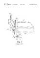
- FIG. 1shows a tilting mechanism used in prior treadmills
- FIG. 2is a front perspective view of a treadmill containing a platform tilting mechanism according to the invention
- FIG. 3is a view of FIG. 1 showing the treadmill in dashed line view in a tilted position;
- FIG. 4is a front perspective view of the FIG. 1 treadmill showing a detail of upright support guide members engaged with positioning sleeve members;
- FIG. 5is a side view of a FIG. 4 upright support and sleeve member showing an arrangement of a driven gear in relation to a rack of teeth on an upright support;
- FIG. 6is a view of FIG. 5 showing in dashed line the treadmill and sleeve component in raised and lowered positions;
- FIGS. 7 and 8are front sectional views of the upright supports, sleeve and driven gear components shown in FIG. 4;
- FIG. 9is a side view of the sleeve component shown in FIGS. 4-5;
- FIG. 10is a side perspective view of the sleeve component shown in FIG. 9;
- FIG. 11is a side exploded view of the upright support, sleeve and gear components shown in FIGS. 5-8 showing the curvature of the upright support in greater detail;
- FIG. 12is a side view of another embodiment of the invention wherein the driven lifting mechanism includes a cable interconnected between an upright support and a platform;
- FIG. 13is a side perspective view of another embodiment of the invention showing a cable interconnected between an upright guide support and a platform via a pulley connected to the platform;
- FIG. 14is a side view of another embodiment of the invention showing a sleeve and a driven worm gear connected to a platform with the worm gear meshed with a complementary rack of teeth on an upright support member;
- FIG. 15is a side view of another embodiment of the invention showing a driven nut engaged with an upright support member having screw teeth.
- FIG. 2shows a treadmill 10 according to the invention comprising a platform on which a user stands, walks or runs.
- the treadmill 10is mounted on a preferably flat, stationary surface 30 via a pair of left and right side rearward wheels 40 which are rotatably connected to the frame 50 and support the platform 20 in a conventional manner.
- the bottom surface of the wheels 40contact the surface 30 at a point 60 and thus act to support the rear end of the frame 50 and all other associated components above the surface 30 .
- the front end of the platform 20 and its associated frame 50are supported above the surface 30 by a pair of left and right side upright supports 70 having bottom ends 85 , FIG. 3 which contact the surface 30 at points 80 .
- the left and right rearward points 60are separated from their respective left and right front points 80 by a straight line distance X, FIG. 1 .
- the bottom ends 85 of supports 70 which make contact with the surface 30comprise a solid material which is resistant to slipping, sliding or rolling on surface 30 , i.e., a material which resists rolling or sliding movement along surface 30 under the weight of the frame 50 and other treadmill components which bear down on the supports 70 (having a weight of at least about 5 lbs).
- Surface 30comprises a conventional floor material such as wood, stone, tile or other material having a relatively high resistance to slipping and relatively high coefficient of friction.
- the bottom ends 85 of supports 70thus most preferably comprise a hard material which makes a hard contact, i.e., non-rolling, non-slipping contact with surface 30 .
- the rearward supports 40may comprise a structure other than a wheel, such as rods, blocks, feet or the like having a bottom end which makes a hard contact with the surface 30 and comprises a non-rollable, non-slidable material in the same manner as described above with reference to bottom ends 85 of supports 70 .
- the hard contact which the bottom ends 85 of supports 70 make with the stationary surface 30provides stability against movement of the treadmill during operation when a user is standing, walking or running on the treadmill platform 20 , particularly when the platform is in the process of tilting upwardly 10 a , FIG. 3, or downwardly from its initial starting position (or otherwise) and the user is simultaneously walking, running or standing on the platform 20 while it is tilting.
- the hard contact which the bottom ends 85 make with surface 30serves to prevent front 26 , back 25 or sideways 27 , 28 movement of the treadmill which is highly preferable when a user is walking or running on the platform 20 in order to provide the highest level of safety for the user and to enable the user to feel stability against motion of the treadmill 10 which might otherwise occur in the front 26 , back 25 or sideways 27 , 28 directions when the user is moving on the platform 20 .
- platform 20typically comprises an endless belt tautly strung around front and rear rollers (not shown) at least one of which rollers is controllably driven by a motor, the drive speed of which is controllable by interconnection to a conventional speed control and/or program mechanism.
- the upper portion 21 of the endless belt on which the user standsis supported on its undersurface by a flat deck, typically comprised of wood or plastic, which is interconnected to the frame 50 and supports the weight of the user who is standing, running or walking on the belt 21 .
- the front end of the frame 50is rigidly connected to a guide sleeve 100 having a slot 105 within which a support 70 is mounted.
- Support 70has a rack of teeth 120 which mesh with gears 110 as shown in FIG. 5 .
- Gears 110are driven by motor 75 , the operation and speed of which is controlled by control mechanism 130 .
- the control mechanism 130may comprise a conventional motor controller and electronic, microprocessor or computer controller which is programmable by the user.
- the sleeves 100serve to hold and maintain the supports 70 in an upright and side-to-side position shown in FIGS. 2-6, 11 .
- the gear 110is rotatably driven and the sleeve 100 travels upwardly 100 a or downwardly 100 b along the length/contour of the supports 70 .
- axles 76are mounted in apertures 77 of guide sleeves 100 which mount and maintain gears 110 in the position shown in FIGS. 2-6.
- guide sleeves 100are rigidly connected or interconnected to the frame 50 , as the guide sleeve 100 moves up 100 a or down 100 b , FIG. 6, the entire frame 50 tilts upwardly 50 a , FIG. 2, or downwardly around the rearward pivot point of contact 60 of supports 40 with the surface 30 .
- the rearward point 60is the pivot point for tilting of the entire frame 50 including the platform 20 .
- the platform 20is tilted upwardly such as 50 a , FIG. 3, the user experiences the effect of walking or running uphill.
- the upright supports 70have a curvature.
- the curvature in the supports 70extends the entirety of the longitudinal length of the supports from top 121 to bottom 122 , FIG. 11 .
- the curvatureneed not necessarily extend the entire length of the support 70 but only along so much of the length of the support 70 , e.g., along length Y, FIG. 11, as is necessary to allow for the maximum degree of tilt as may be intended for users of the treadmill 10 .
- the curvature of the support 70 , FIGS. 2-6, 11is determined by the distance X between the point 90 of engagement of the gear 110 with the rack of teeth 120 , FIGS. 2, 5 , 11 and the pivot point 60 . More generally apart from the specific embodiment shown in FIGS. 2-11, the curvature of the supports is determined by the distance between the point 90 (or 91 or 92 or 93 or 94 , FIGS. 12-15) where the front end of the frame 50 is effectively engaged with and supported by contact with the support 70 (or 71 , 73 , 77 , 78 , Fits. 12 - 15 ) and the pivot point 60 . This distance is the longitudinal pivot length of the treadmill.
- the support 70is provided with a circular curvature having a radius equal to X.
- the driven componentsuch as gear 110
- the front end of the framemoves upwardly and the distance X between the point of engagement 90 and point 60 does not change.
- the frame 50will thus not be subject to any force which will tend to move the frame 50 in any forward 26 or backward direction and the frame is thus stabilized against movement.
- FIG. 1In prior treadmills, FIG. 1, upright supports 500 which were sometimes utilized for effecting a front end lifting of a platform 410 , were straight leaving no longitudinal curvature. Straight uprights 500 cause the front end of the frame 420 to be pulled forwardly or backwardly 430 as the front end is driven upwardly or downwardly 440 thus necessitating the use of a front wheel 400 as the support for the frame 420 to avoid dragging of the feet of the treadmill along the floor.
- the front to back 430 movement, FIG. 1,also renders the prior machines unstable to the user standing, walking or running on the treadmill.
- the curved upright support 71is effectively engaged with the front end of the frame 51 by sleeve 200 which is rigidly connected to the frame 50 .
- the support 71is inserted within a complementary guide slot 201 within the sleeve 200 .
- the effective engagement pointis 91 within sleeve 200 which follows along the curvature of support 71 .
- the front end of the framehas a pulley wheel 210 around which a cable 220 extends.
- the cable 220is connected at one end to an upper point 72 of the support 71 and windably connected at another end to a controllably driven windup pulley 230 .
- the windup pulley 230is controllably driven by motor 240 and drive control mechanism 250 in the same conventional drive control manner as described above with reference to FIGS. 2-11.
- the pulley 230winds the cable 220 up
- the front end of the frame 51moves upwardly by virtue of the cable 220 pushing upwardly on the underside of pulley 210 .
- support 71has a radius of curvature X as shown in FIG. 12 .
- a cable 221is shown as connected at opposite ends to the top 75 and bottom 76 ends of support 73 and is wound around drive pulley 231 .
- Pulley 231is controllably driven around its axis by motor 251 and associated drive control mechanisms. As pulley 231 is driven counterclockwise, the front end of the frame 52 moves upwardly 245 and as pulley 231 is driven counterclockwise, the front end of the frame 52 moves downwardly 246 .
- the axle 232 of the pulleyis mounted in an aperture within the frame at point 92 which defines the effective engagement point with the curved uprights 73 .
- upright supports 73have a radius of curvature X as shown in FIG. 13 .
- the embodiment shown in FIG. 14utilizes a driven screw 300 to engage with a rack of teeth 122 provided on curved upright 77 .
- the gear 300is driven by a motor 330 the speed and operation of which is controllable by controller 252 .
- Gear 300is fixedly connected or interconnected to sleeve 310 which is connected to the frame 50 of the treadmill.
- the controller 252typically includes a program for controlling the drive of motor 330 .
- the support 77is held in meshed engagement with gear 300 by a guide bracket 311 which is attached to sleeve 310 .
- a driven nut 600is rotatably mounted in a sleeve 610 which is rigidly connected or interconnected to the front end of the frame 50 of the treadmill.
- the nutis engaged with support 78 which has screw threads 620 , complementary to the nut 600 threads, extending to the longitudinal length of the support.
- the support 78has a radius of curvature X equal to the distance X between the pivot point 60 and the point 94 which the nut 600 effectively engaged the support 78 .
- the nut 600is rotatably driven via a belt 630 which is driven by motor 640 the operation and speed which is controlled by controller 253 .
- the supports 70 , 71 , 73 , 77 , 78comprise an elongated rod, bar and the like comprised of a rigid material such as metal which is capable of supporting a relatively high degree of weight for the purposes described herein, i.e., for supporting the weight of the front end of a treadmill in addition to the weight of one or more persons standing, walking or running on platform 20 .
Landscapes
- Health & Medical Sciences (AREA)
- Cardiology (AREA)
- Vascular Medicine (AREA)
- General Health & Medical Sciences (AREA)
- Physical Education & Sports Medicine (AREA)
- Rehabilitation Tools (AREA)
Abstract
Description
Claims (5)
Priority Applications (1)
| Application Number | Priority Date | Filing Date | Title |
|---|---|---|---|
| US09/421,582US6254515B1 (en) | 1999-10-20 | 1999-10-20 | Apparatus for stabilizing a treadmill |
Applications Claiming Priority (1)
| Application Number | Priority Date | Filing Date | Title |
|---|---|---|---|
| US09/421,582US6254515B1 (en) | 1999-10-20 | 1999-10-20 | Apparatus for stabilizing a treadmill |
Publications (1)
| Publication Number | Publication Date |
|---|---|
| US6254515B1true US6254515B1 (en) | 2001-07-03 |
Family
ID=23671159
Family Applications (1)
| Application Number | Title | Priority Date | Filing Date |
|---|---|---|---|
| US09/421,582Expired - Fee RelatedUS6254515B1 (en) | 1999-10-20 | 1999-10-20 | Apparatus for stabilizing a treadmill |
Country Status (1)
| Country | Link |
|---|---|
| US (1) | US6254515B1 (en) |
Cited By (34)
| Publication number | Priority date | Publication date | Assignee | Title |
|---|---|---|---|---|
| US6432026B1 (en)* | 2000-07-21 | 2002-08-13 | Leao Wang | Height-adjustable mechanism for a running frame of a treadmill |
| US6719669B1 (en)* | 2003-04-11 | 2004-04-13 | Leao Wang | Displacement detector of a shock absorption unit for a treadmill |
| US6776740B1 (en) | 1999-09-07 | 2004-08-17 | Brunswick Corporation | Treadmill mechanism |
| US20040204295A1 (en)* | 2003-04-11 | 2004-10-14 | Leao Wang | Displacement detector of a platform for an exercise apparatus |
| US20050255969A1 (en)* | 2004-05-12 | 2005-11-17 | Smith Jeffrey A | Folding mechanism for a treadmill |
| FR2891536A1 (en)* | 2005-09-28 | 2007-04-06 | Forhouse Corp | Running base lifting mechanism for exercise device running belt has flexible connecting element for driving movable end of drive mechanism to turn plank on lever support up and down |
| US20090286390A1 (en)* | 2006-11-17 | 2009-11-19 | Freescale Semiconductor, Inc. | Method of packaging a semiconductor device and a prefabricated connector |
| US9616278B2 (en) | 2014-08-29 | 2017-04-11 | Icon Health & Fitness, Inc. | Laterally tilting treadmill deck |
| CN106890425A (en)* | 2017-04-14 | 2017-06-27 | 山东体育学院 | A kind of two-sided adjustable slope ankle joint exercise machine |
| US20170326409A1 (en)* | 2016-05-16 | 2017-11-16 | Matthew Boyd Burkhardt | Flexor and extensor exercise device |
| CN109260666A (en)* | 2018-11-23 | 2019-01-25 | 牡丹江师范学院 | A kind of sport lift pressing-leg device |
| US10188890B2 (en) | 2013-12-26 | 2019-01-29 | Icon Health & Fitness, Inc. | Magnetic resistance mechanism in a cable machine |
| US10212994B2 (en) | 2015-11-02 | 2019-02-26 | Icon Health & Fitness, Inc. | Smart watch band |
| US10252109B2 (en) | 2016-05-13 | 2019-04-09 | Icon Health & Fitness, Inc. | Weight platform treadmill |
| US10258828B2 (en) | 2015-01-16 | 2019-04-16 | Icon Health & Fitness, Inc. | Controls for an exercise device |
| US10272317B2 (en) | 2016-03-18 | 2019-04-30 | Icon Health & Fitness, Inc. | Lighted pace feature in a treadmill |
| US10279212B2 (en) | 2013-03-14 | 2019-05-07 | Icon Health & Fitness, Inc. | Strength training apparatus with flywheel and related methods |
| US10293211B2 (en) | 2016-03-18 | 2019-05-21 | Icon Health & Fitness, Inc. | Coordinated weight selection |
| US20190192898A1 (en)* | 2017-12-22 | 2019-06-27 | Icon Health & Fitness, Inc. | Inclinable Exercise Machine |
| US10343017B2 (en) | 2016-11-01 | 2019-07-09 | Icon Health & Fitness, Inc. | Distance sensor for console positioning |
| US10376736B2 (en) | 2016-10-12 | 2019-08-13 | Icon Health & Fitness, Inc. | Cooling an exercise device during a dive motor runway condition |
| US10426989B2 (en) | 2014-06-09 | 2019-10-01 | Icon Health & Fitness, Inc. | Cable system incorporated into a treadmill |
| US10433612B2 (en) | 2014-03-10 | 2019-10-08 | Icon Health & Fitness, Inc. | Pressure sensor to quantify work |
| US10441844B2 (en) | 2016-07-01 | 2019-10-15 | Icon Health & Fitness, Inc. | Cooling systems and methods for exercise equipment |
| US10471299B2 (en) | 2016-07-01 | 2019-11-12 | Icon Health & Fitness, Inc. | Systems and methods for cooling internal exercise equipment components |
| US10493349B2 (en) | 2016-03-18 | 2019-12-03 | Icon Health & Fitness, Inc. | Display on exercise device |
| US10500473B2 (en) | 2016-10-10 | 2019-12-10 | Icon Health & Fitness, Inc. | Console positioning |
| US10543395B2 (en) | 2016-12-05 | 2020-01-28 | Icon Health & Fitness, Inc. | Offsetting treadmill deck weight during operation |
| US10561894B2 (en) | 2016-03-18 | 2020-02-18 | Icon Health & Fitness, Inc. | Treadmill with removable supports |
| US10625137B2 (en) | 2016-03-18 | 2020-04-21 | Icon Health & Fitness, Inc. | Coordinated displays in an exercise device |
| US10661114B2 (en) | 2016-11-01 | 2020-05-26 | Icon Health & Fitness, Inc. | Body weight lift mechanism on treadmill |
| US10729965B2 (en) | 2017-12-22 | 2020-08-04 | Icon Health & Fitness, Inc. | Audible belt guide in a treadmill |
| US10953305B2 (en) | 2015-08-26 | 2021-03-23 | Icon Health & Fitness, Inc. | Strength exercise mechanisms |
| US11451108B2 (en) | 2017-08-16 | 2022-09-20 | Ifit Inc. | Systems and methods for axial impact resistance in electric motors |
Citations (1)
| Publication number | Priority date | Publication date | Assignee | Title |
|---|---|---|---|---|
| US6013012A (en)* | 1998-05-05 | 2000-01-11 | Cybex International, Inc. | Apparatus for stabilizing a treadmill |
- 1999
- 1999-10-20USUS09/421,582patent/US6254515B1/ennot_activeExpired - Fee Related
Patent Citations (1)
| Publication number | Priority date | Publication date | Assignee | Title |
|---|---|---|---|---|
| US6013012A (en)* | 1998-05-05 | 2000-01-11 | Cybex International, Inc. | Apparatus for stabilizing a treadmill |
Cited By (39)
| Publication number | Priority date | Publication date | Assignee | Title |
|---|---|---|---|---|
| US6776740B1 (en) | 1999-09-07 | 2004-08-17 | Brunswick Corporation | Treadmill mechanism |
| US6432026B1 (en)* | 2000-07-21 | 2002-08-13 | Leao Wang | Height-adjustable mechanism for a running frame of a treadmill |
| US20040204295A1 (en)* | 2003-04-11 | 2004-10-14 | Leao Wang | Displacement detector of a platform for an exercise apparatus |
| US6953419B2 (en)* | 2003-04-11 | 2005-10-11 | Leao Wang | Displacement detector of a platform for an exercise apparatus |
| US6719669B1 (en)* | 2003-04-11 | 2004-04-13 | Leao Wang | Displacement detector of a shock absorption unit for a treadmill |
| US20050255969A1 (en)* | 2004-05-12 | 2005-11-17 | Smith Jeffrey A | Folding mechanism for a treadmill |
| US7041038B2 (en)* | 2004-05-12 | 2006-05-09 | Smith Jeffrey A | Folding mechanism for a treadmill |
| FR2891536A1 (en)* | 2005-09-28 | 2007-04-06 | Forhouse Corp | Running base lifting mechanism for exercise device running belt has flexible connecting element for driving movable end of drive mechanism to turn plank on lever support up and down |
| US20090286390A1 (en)* | 2006-11-17 | 2009-11-19 | Freescale Semiconductor, Inc. | Method of packaging a semiconductor device and a prefabricated connector |
| US10279212B2 (en) | 2013-03-14 | 2019-05-07 | Icon Health & Fitness, Inc. | Strength training apparatus with flywheel and related methods |
| US10188890B2 (en) | 2013-12-26 | 2019-01-29 | Icon Health & Fitness, Inc. | Magnetic resistance mechanism in a cable machine |
| US10433612B2 (en) | 2014-03-10 | 2019-10-08 | Icon Health & Fitness, Inc. | Pressure sensor to quantify work |
| US10426989B2 (en) | 2014-06-09 | 2019-10-01 | Icon Health & Fitness, Inc. | Cable system incorporated into a treadmill |
| US9616278B2 (en) | 2014-08-29 | 2017-04-11 | Icon Health & Fitness, Inc. | Laterally tilting treadmill deck |
| US10258828B2 (en) | 2015-01-16 | 2019-04-16 | Icon Health & Fitness, Inc. | Controls for an exercise device |
| US10953305B2 (en) | 2015-08-26 | 2021-03-23 | Icon Health & Fitness, Inc. | Strength exercise mechanisms |
| US10212994B2 (en) | 2015-11-02 | 2019-02-26 | Icon Health & Fitness, Inc. | Smart watch band |
| US10272317B2 (en) | 2016-03-18 | 2019-04-30 | Icon Health & Fitness, Inc. | Lighted pace feature in a treadmill |
| US10293211B2 (en) | 2016-03-18 | 2019-05-21 | Icon Health & Fitness, Inc. | Coordinated weight selection |
| US10625137B2 (en) | 2016-03-18 | 2020-04-21 | Icon Health & Fitness, Inc. | Coordinated displays in an exercise device |
| US10561894B2 (en) | 2016-03-18 | 2020-02-18 | Icon Health & Fitness, Inc. | Treadmill with removable supports |
| US10493349B2 (en) | 2016-03-18 | 2019-12-03 | Icon Health & Fitness, Inc. | Display on exercise device |
| US10252109B2 (en) | 2016-05-13 | 2019-04-09 | Icon Health & Fitness, Inc. | Weight platform treadmill |
| US10625112B2 (en)* | 2016-05-16 | 2020-04-21 | Matthew Boyd Burkhardt | Flexor and extensor exercise device |
| US20170326409A1 (en)* | 2016-05-16 | 2017-11-16 | Matthew Boyd Burkhardt | Flexor and extensor exercise device |
| US10471299B2 (en) | 2016-07-01 | 2019-11-12 | Icon Health & Fitness, Inc. | Systems and methods for cooling internal exercise equipment components |
| US10441844B2 (en) | 2016-07-01 | 2019-10-15 | Icon Health & Fitness, Inc. | Cooling systems and methods for exercise equipment |
| US10500473B2 (en) | 2016-10-10 | 2019-12-10 | Icon Health & Fitness, Inc. | Console positioning |
| US10376736B2 (en) | 2016-10-12 | 2019-08-13 | Icon Health & Fitness, Inc. | Cooling an exercise device during a dive motor runway condition |
| US10343017B2 (en) | 2016-11-01 | 2019-07-09 | Icon Health & Fitness, Inc. | Distance sensor for console positioning |
| US10661114B2 (en) | 2016-11-01 | 2020-05-26 | Icon Health & Fitness, Inc. | Body weight lift mechanism on treadmill |
| US10543395B2 (en) | 2016-12-05 | 2020-01-28 | Icon Health & Fitness, Inc. | Offsetting treadmill deck weight during operation |
| CN106890425A (en)* | 2017-04-14 | 2017-06-27 | 山东体育学院 | A kind of two-sided adjustable slope ankle joint exercise machine |
| US11451108B2 (en) | 2017-08-16 | 2022-09-20 | Ifit Inc. | Systems and methods for axial impact resistance in electric motors |
| US20190192898A1 (en)* | 2017-12-22 | 2019-06-27 | Icon Health & Fitness, Inc. | Inclinable Exercise Machine |
| US10729965B2 (en) | 2017-12-22 | 2020-08-04 | Icon Health & Fitness, Inc. | Audible belt guide in a treadmill |
| US11058913B2 (en)* | 2017-12-22 | 2021-07-13 | Icon Health & Fitness, Inc. | Inclinable exercise machine |
| CN109260666B (en)* | 2018-11-23 | 2020-03-06 | 牡丹江师范学院 | A lifting leg press device for sports |
| CN109260666A (en)* | 2018-11-23 | 2019-01-25 | 牡丹江师范学院 | A kind of sport lift pressing-leg device |
Similar Documents
| Publication | Publication Date | Title |
|---|---|---|
| US6254515B1 (en) | Apparatus for stabilizing a treadmill | |
| US6135925A (en) | Running exerciser | |
| EP2838623B1 (en) | Exercise device with rack and pinion incline adjusting mechanism | |
| US5769759A (en) | Stair climbing apparatus | |
| US6241638B1 (en) | Fold-up exercise treadmill and method | |
| CN1160139C (en) | folding treadmill | |
| US5195935A (en) | Exercise apparatus with automatic variation of provided passive and active exercise without interruption of the exercise | |
| TWI576137B (en) | Ladder machine | |
| US4844449A (en) | Infinitely adjustable elevating system for treadmill | |
| US6923747B1 (en) | Foldable treadmill | |
| US6878101B2 (en) | Treadmill with adjustable platforms | |
| US6945912B2 (en) | Exercise treadmill with slope adjustment | |
| US8170780B2 (en) | Apparatus and method for control of a vehicle | |
| US20120149533A1 (en) | Treadmill deck support | |
| CN1372481A (en) | Function strengthening training machine | |
| US5044473A (en) | Elevator work station apparatus | |
| WO1994019068A1 (en) | Aerobic exercise device | |
| WO2009126904A2 (en) | Wheelchair accessible treadmill | |
| CA2249722A1 (en) | Treadmill for wheelchair | |
| US6013012A (en) | Apparatus for stabilizing a treadmill | |
| US20090312157A1 (en) | Stationary exercise apparatus | |
| KR100668623B1 (en) | Walking exercise equipment | |
| KR102578355B1 (en) | Skateboard having structure for converting linear reciprocating motion to rotational motion | |
| JPH0717322Y2 (en) | Tilt device for treadmill | |
| CN212047729U (en) | Self-operated pulley |
Legal Events
| Date | Code | Title | Description |
|---|---|---|---|
| AS | Assignment | Owner name:CYBEX INTERNATIONAL, INC., MASSACHUSETTS Free format text:ASSIGNMENT OF ASSIGNORS INTEREST;ASSIGNORS:CARMAN, MICHAEL;THEROUX, GERARD J.;GIANNELLI, RAYMOND;REEL/FRAME:010339/0287 Effective date:19980504 | |
| AS | Assignment | Owner name:HILCO CAPITAL LLP, ILLINOIS Free format text:SECURITY INTEREST;ASSIGNOR:CYBEX INTERNATIONAL, INC.;REEL/FRAME:013879/0826 Effective date:20030716 | |
| AS | Assignment | Owner name:CIT GROUP/BUSINESS CREDIT, INC., THE, NORTH CAROLI Free format text:NOTICE OF GRANT OF SECURITY INTEREST;ASSIGNOR:CYBEX INTERNATIONAL, INC.;REEL/FRAME:013913/0712 Effective date:20030716 | |
| FPAY | Fee payment | Year of fee payment:4 | |
| AS | Assignment | Owner name:CYBEX INTERNATIONAL, INC., MASSACHUSETTS Free format text:RELEASE OF SECURITY INTEREST;ASSIGNOR:HILCO CAPITAL, LP;REEL/FRAME:016309/0328 Effective date:20040713 | |
| REMI | Maintenance fee reminder mailed | ||
| LAPS | Lapse for failure to pay maintenance fees | ||
| STCH | Information on status: patent discontinuation | Free format text:PATENT EXPIRED DUE TO NONPAYMENT OF MAINTENANCE FEES UNDER 37 CFR 1.362 | |
| FP | Lapsed due to failure to pay maintenance fee | Effective date:20090703 | |
| AS | Assignment | Owner name:CYBEX INTERNATIONAL, INC., MASSACHUSETTS Free format text:RELEASE BY SECURED PARTY;ASSIGNOR:CIT GROUP/BUSINESS CREDIT, INC.;REEL/FRAME:026046/0651 Effective date:20110328 |