US6253835B1 - Isothermal heat sink with converging, diverging channels - Google Patents
Isothermal heat sink with converging, diverging channelsDownload PDFInfo
- Publication number
- US6253835B1 US6253835B1US09/502,321US50232100AUS6253835B1US 6253835 B1US6253835 B1US 6253835B1US 50232100 AUS50232100 AUS 50232100AUS 6253835 B1US6253835 B1US 6253835B1
- Authority
- US
- United States
- Prior art keywords
- channels
- channel
- group
- heat sink
- fluid
- Prior art date
- Legal status (The legal status is an assumption and is not a legal conclusion. Google has not performed a legal analysis and makes no representation as to the accuracy of the status listed.)
- Expired - Lifetime
Links
Images


Classifications
- F—MECHANICAL ENGINEERING; LIGHTING; HEATING; WEAPONS; BLASTING
- F28—HEAT EXCHANGE IN GENERAL
- F28F—DETAILS OF HEAT-EXCHANGE AND HEAT-TRANSFER APPARATUS, OF GENERAL APPLICATION
- F28F3/00—Plate-like or laminated elements; Assemblies of plate-like or laminated elements
- F28F3/12—Elements constructed in the shape of a hollow panel, e.g. with channels
- F—MECHANICAL ENGINEERING; LIGHTING; HEATING; WEAPONS; BLASTING
- F28—HEAT EXCHANGE IN GENERAL
- F28F—DETAILS OF HEAT-EXCHANGE AND HEAT-TRANSFER APPARATUS, OF GENERAL APPLICATION
- F28F13/00—Arrangements for modifying heat-transfer, e.g. increasing, decreasing
- F28F13/06—Arrangements for modifying heat-transfer, e.g. increasing, decreasing by affecting the pattern of flow of the heat-exchange media
- F28F13/08—Arrangements for modifying heat-transfer, e.g. increasing, decreasing by affecting the pattern of flow of the heat-exchange media by varying the cross-section of the flow channels
- H—ELECTRICITY
- H01—ELECTRIC ELEMENTS
- H01L—SEMICONDUCTOR DEVICES NOT COVERED BY CLASS H10
- H01L23/00—Details of semiconductor or other solid state devices
- H01L23/34—Arrangements for cooling, heating, ventilating or temperature compensation ; Temperature sensing arrangements
- H01L23/46—Arrangements for cooling, heating, ventilating or temperature compensation ; Temperature sensing arrangements involving the transfer of heat by flowing fluids
- H01L23/473—Arrangements for cooling, heating, ventilating or temperature compensation ; Temperature sensing arrangements involving the transfer of heat by flowing fluids by flowing liquids
- F—MECHANICAL ENGINEERING; LIGHTING; HEATING; WEAPONS; BLASTING
- F28—HEAT EXCHANGE IN GENERAL
- F28F—DETAILS OF HEAT-EXCHANGE AND HEAT-TRANSFER APPARATUS, OF GENERAL APPLICATION
- F28F2210/00—Heat exchange conduits
- F28F2210/02—Heat exchange conduits with particular branching, e.g. fractal conduit arrangements
- H—ELECTRICITY
- H01—ELECTRIC ELEMENTS
- H01L—SEMICONDUCTOR DEVICES NOT COVERED BY CLASS H10
- H01L2924/00—Indexing scheme for arrangements or methods for connecting or disconnecting semiconductor or solid-state bodies as covered by H01L24/00
- H01L2924/0001—Technical content checked by a classifier
- H01L2924/0002—Not covered by any one of groups H01L24/00, H01L24/00 and H01L2224/00
Definitions
- the present inventionis generally related to providing cooling systems for electronic devices requiring cooling. More particularly, the present invention is directed to an isothermal heat sink for uniformly cooling an electronics module.
- CMOS circuitsdissipate less power than bipolar circuits. This has permitted more dense packaging and correspondingly, faster CMOS circuits.
- MCMsmultichip modules
- thermal energyis the single biggest impediment to semiconductor operation integrity.
- Multichannel heat sinkshave been developed for extraction of heat generated by, for example, integrated electronic circuits, multi-chip modules, diode laser arrays, or other electro-optic devices under conditions of high heat flux density. Coolant flow in the channels is conventionally unidirectional, i.e., the coolant enters the heat sink through an inlet at one end and flows through parallel channels to an outlet at the other end.
- the present inventioncomprises in one aspect an apparatus for cooling an electronic device which includes a heat sink member with a surface for making thermal contact with the electronic device.
- the heat sink memberincludes a plurality of channels formed therein for carrying coolant fluid.
- the plurality of channelscomprise a first group of channels and a second group of channels, wherein the first group of channels and the second group of channels are positioned generally alternately across the heat sink member so that coolant flow alternates direction across the member.
- At least one channel of the first group of channels and the second group of channelshas a channel cross-section that varies over a length thereof to enhance a heat transfer coefficient of the coolant fluid within the at least one channel at a selected section of the at least one channel and thereby produce a more uniform temperature at the surface of the heat sink member when making thermal contact with the electronic device. More particularly, at least some channels of the first group of channels and the second group of channels preferably have a fluid flow cross-section which tends to converge near a center portion of the heat sink member and diverge thereafter.
- an isothermal heat sinkfor use in a cooling system of an electronic device.
- Enhanced performance of the cooling systemis attained by more uniformly dissipating heat across the thermal interface surface of the heat sink, thereby more uniformly cooling the electronic device to which the heat sink is coupled.
- thermal resistance between the heat sink and electronic deviceis lowered.
- timing (synchronization) and noise tolerancesare a function of electronic device temperature, maintaining circuits as isothermal as possible minimizes the temperature effect resulting in improved noise margin and clock skew. This effect is more pronounced in multichip modules.
- FIG. 1depicts one embodiment of a heat sink 10 having multiple channels 12 therethrough within which coolant fluid is to flow in accordance with the principles of the present invention
- FIG. 1Adepicts a side elevational view of the heat sink of FIG. 1, with uniform heat flux illustrated from an electronic device (shown in phantom);
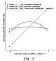
- FIG. 2is a graph showing variation in bottom surface temperature for the heat sink of FIG. 1 using different coolant fluid flow and channel configurations in accordance with the present invention
- FIG. 3is a plan view of one embodiment of a heat sink wherein the direction of coolant fluid flow alternates across the heat sink;
- FIG. 3Ais a cross-sectional view of the heat sink embodiment of FIG. 3 taken along lines A—A;
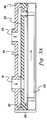
- FIG. 4is a plan view of another embodiment of a heat sink having a plurality of channels for carrying coolant flow in alternating directions, and wherein a cross-section of each channel tends to converge near a middle portion of the heat sink and diverge thereafter in accordance with the principles of the present invention
- FIG. 4Ais cross-sectional view of the heat sink embodiment of FIG. 4 taken along lines A—A;
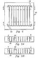
- FIG. 5is a plan view of another embodiment of a heat sink in accordance with the principles of the present invention wherein a first serpentine channel and a second serpentine channel are disposed one on top of the other such that the heat sink comprises a tiered structure;
- FIGS. 5A and 5Bare cross-section views of the heat sink embodiment of FIG. 5 taken along lines A—A and B—B, respectively;
- FIG. 6Ais a graph of the heat transfer coefficient of fluid flow within a channel such as depicted in FIG. 6B;
- FIG. 6Bis a plan view of a heat sink channel with fluid flow from left to right;
- FIG. 7Ais a graph of variation of a heat transfer coefficient versus channel position for fluid flow within the heat sink channel of FIG. 7B;
- FIG. 7Billustrates the affects of cross-flow slots on fluid boundary layer development within a heat sink channel in accordance with the principles of the present invention
- FIG. 8is a plan view of a further embodiment of a heat sink in accordance with the principles of the present invention, wherein cross-flow openings are provided between adjacent primary flow channels to disrupt boundary layers formed within the primary flow channels;
- FIG. 8Ais cross-sectional view of the heat sink of FIG. 8 taken along lines A—A;
- FIG. 9Ais a graph of fluid pressure versus channel position as coolant fluid moves left to right and right to left within the channels of the heat sink of FIG. 8;
- FIG. 9Bis a partially enlarged portion of the heat sink of FIG. 8 correlated to the fluid pressure graph of FIG. 9 A.
- FIG. 1depicts one embodiment of a heat sink, generally denoted 10 , to employ counter coolant fluid flow in alternating channels in accordance with the principles of the present invention.
- Heat sink 10has a plurality of channels 12 , each with length L, through which cooling fluid is to be passed.
- heat sink 10is shown to have a bottom surface 13 designed to thermally interface with an electronic device 14 (shown in phantom). Ideally, a uniform heat flux is to be established for dissipation by the heat sink.
- FIG. 2is a graph of thermal effectiveness of various cooling approaches, two of which might employ the heat sink of FIG. 1 .
- Curve A of FIG. 2represents a conventional, parallel flow of cooling fluid through multiple uniform channels wherein bottom surface temperature of the heat sink increases with distance along the channel length. This curve assumes fluid flow in a direction left to right through the heat sink.
- a better approach, referred to herein as a counter flow arrangement,is to provide cooling fluid flows in alternate directions in adjacent channels in the heat sink.
- the thermal characteristics of this approachare represented by curve B in FIG. 2 .
- the goal of the present inventionis to provide various cooling apparatus which further enhance, i.e., flatten, thermal variation across the interface of the heat sink compared with the response characteristic of curve B.
- FIG. 3depicts a plan view of a counter flow arrangement to a heat sink 20 .
- heat sink 20includes multiple channels 22 which are constructed so that coolant flows right to left in a first group of channels 22 a and left to right in a second group of channels 22 b .
- Fluidenters through inlets 24 a in channels 22 a and exits through outlets 26 a , and enters through inlets 24 b in channels 22 b and exits through outlets 26 b .
- FIG. 3Adepicts one embodiment for implementing this concept.
- an inlet plenum 30is provided within the heat sink for supplying the plurality of inlets 24 a & 24 b and an outlet plenum 34 is provided for receiving expelled cooling fluid from the channels though outlets 26 a & 26 b .
- cooling fluidenters inlet plenum 30 through at least one principal inlet 31 and flows down through inlets 24 a & 24 b to counter propagate through the channels of the heat sink and be expelled through outlets 26 a & 26 b into outlet plenum 34 , where the heated coolant is removed through at least one principal outlet 35 .
- Inlet plenum 30is shown disposed within a first layer 32 , while outlet plenum 34 resides within a second layer 36 .
- layers 32 and 36could comprise thermal insulation layers.
- Inlet plenum 30could thus be thermally isolated from outlet plenum 34 .
- the outlet plenumis disposed away from the plurality of channels, with the inlet plenum disposed directly atop the plurality of channels.
- curve B in FIG. 2depicts the improved thermal characteristics of the heat sink of FIG. 3, i.e., compared with the conventional unidirectional flow of coolant represented by curve A.
- curve B in FIG. 2depicts the improved thermal characteristics of the heat sink of FIG. 3, i.e., compared with the conventional unidirectional flow of coolant represented by curve A.
- further enhancements to this basic counter flow (and uniform channel cross-section) embodimentare desired since the goal is to achieve an isothermal distribution across the heat sink.
- FIGS. 4 & 4Awherein heat sink 40 is shown to have a cooling region 42 where multiple channels 44 are disposed substantially in parallel, with the coolant flow direction again being opposite in neighboring channels 46 a & 46 b , but with the fluid flow cross-section of each channel varying.
- the variationsare such that the channels tend to converge to a minimum cross-section near a center portion X of the heat sink and diverge thereafter to a common cross-section at either side.
- the channelsare equally wide at both ends but narrow to a predetermined minimum width in the center region.
- This structureis referred to herein as a converging, diverging channel.
- thermal distribution curve C(FIG. 2) can be obtained, which shows the goal of an isothermal heat sink being more closely attained.
- FIG. 4Adepicts a cross-sectional view of heat sink 40 taken along lines A—A of FIG. 4 .
- the plurality of channels 44are shown to include tapered restrictions 48 which achieve the desired convergence (to some minimal size opening) of the coolant flow cross-section through each channel near center portion X of the cooling region 42 , followed by divergence thereof, for example, back to the original cross-sectional dimension.
- the common channel width at either end of a channelmight be approximately lmm or greater, while the channel width might taper to 0.3 to 0.7 mm near the center portion of the cooling region.
- FIGS. 5, 5 A & 5 Bdepict an alternate heat sink 50 having an enhanced isothermal characteristic.
- a tiered, serpentine counter flow arrangementis provided. Specifically, two independent flow channels 52 & 54 are stacked one atop the other as shown in FIGS. 5A & 5B. Coolant flow enters the lower tier channel 54 at inlet 2 and exits at outlet 1 , while coolant flow enters the upper tier channel 52 at inlet 3 and exits at outlet 4 .
- FIGS. 5, 5 A & 5 BWhen considering that heat that is transferred to heat sink 50 is conducted from the bottom surface up into the coolant flow within the channels, the arrangement of FIGS. 5, 5 A & 5 B results in the coldest fluid in the upper tier 52 being coupled with the warmest fluid in the lower tier 54 , and vice versa. It is this coupling that results in this embodiment in a more uniform surface temperature at the bottom surface of the heat sink. Notice also that, for purposes of illustration, the geometry of the upper channel 52 is different from that of the lower channel 54 . This can be done to optimize both heat transfer and temperature distribution.
- This tiered arrangementcan be manufactured by a variety of techniques, including brazing or soldering subsections in a manner comparable to the method used to manufacture other cold plates in the art.
- FIG. 6Bprovides a plan view looking down upon a cold-plate passage (defined by walls 56 ) with fluid flowing from left to right. Fluid enters the passage at position A with a uniform velocity profile 55 with respect to the y coordinate. Due to viscous effects a fluid boundary layer 57 begins to form, and as may be seen at position B downstream from the entrance, the fluid velocity varies from zero at the wall to 99% of the free-stream velocity at the edge of the boundary layer. As flow moves along the passage, the boundary layer continues to grow in thickness. As is shown, a boundary layer also forms along the opposing wall of the passage. Eventually, the two boundary layers will grow to the point at which they merge and totally occupy the passage as shown at point C.
- the heat transfer coefficient or rate at which heat is transferred from the surface to the fluid per unit temperature differenceis ultimately associated with the development of the hydrodynamic and thermal boundary layers in convective processes.
- the heat transfer coefficientdecreases in magnitude. This is shown by the graph of FIG. 6A depicting the variation in the magnitude of the heat transfer coefficient, h, with distance, x, along the flow passage.
- the magnitude of his very high near the flow entrance and decreases as flow moves down the passage and the boundary layers thicken.
- the heat transfer coefficientreaches a constant value which remains the same throughout the fully developed region.
- FIGS. 7A & 7Billustrate the effects of cross-flow slots (as disclosed by FIGS. 8-9B) on fluid boundary layer development and the corresponding heat transfer coefficients.
- FIG. 7Bmay be seen a fluid passage with the primary cooling flow moving from left-to-right beginning from an entrance velocity profile 61 .
- this passageBelow and above this passage are shown one-half of the two adjacent flow passages with fluid flow moving right-to-left.
- the associated boundary layersare shown in each of the passages.
- the initial development of the fluid boundary layeris depicted much the same as described above.
- slotsare provided at point B connecting the center passage with the two adjacent passages which have fluid moving in the opposite direction.
- the higher pressure in the two adjacent channelswill cause fluid to enter the slots from the higher pressure sides and exit into the lower pressure side (i.e., the center channel) as a slot jet 63 disrupting and breaking up the boundary layer at the wall.
- the flowis shown reattaching to the wall and beginning the development of a new boundary layer.
- FIG. 7Aillustrating the variation of h with the distance along the center flow passage, the heat transfer coefficient will be significantly higher at and immediately following the point where the flow reattaches to the channel surface and the new boundary layer begins.
- the average heat transfer coefficient acting over the total length of the flow passageis increased above the average value pertaining to the case without slot jets, thereby increasing the total heat transfer rate.
- FIGS. 8 & 8Adepict one embodiment of an isothermal evaporator/cold head which employs slot jets in accordance with this aspect of the present invention.
- an arrangement of parallel flow channels 62also referred to herein as primary flow channels, is provided which is similar to those discussed above. Fluid flow within adjacent primary flow channels 62 is preferably counter propagating.
- the principle difference in this embodimentis the provision of cross-flow slots or openings 64 perpendicular to and connecting adjacent primary flow channels. Again, the purpose of slots 64 is to introduce flow jets normal to the fluid boundary layer formed along the walls of the primary flow channels.
- FIGS. 9A & 9Bfor a channel with fluid flowing in a left-to-right (L-R) direction, some fluid will flow out of the channel along the left half of the channel into the adjacent channels with flow in a right-to-left (R-L) direction. Conversely, in the right half of the channel fluid will flow into the channel from the two adjacent channels.
- the amount of fluid flowing through a slotmay be controlled by the width of the slot, and in all cases the amount of cross-flow is maintained small (e.g., a few percent of the primary flow). It may be noted, that for purposes of illustration, the widths of the slots shown in FIGS. 8, 8 A & 9 B are disproportionately large compared with the width of the primary flow channels.
- the relative widths of the slotsmay increase towards the middle of the channels to compensate for the reduced pressure differentials available to drive the slot jets in this region.
- the width of the cross-flow slotsmight vary from 0.1 mm near either end of the primary flow channel to 0.2 mm near the center.
- an isothermal heat sinkfor use in cooling in an electronic device.
- Enhanced performance of the electronic deviceis thus attained by more uniformly dissipating heat across the thermal interface surface of the heat sink, thereby more uniformly cooling the electronic device and enhancing performance thereof.
Landscapes
- Engineering & Computer Science (AREA)
- Physics & Mathematics (AREA)
- Thermal Sciences (AREA)
- Mechanical Engineering (AREA)
- General Engineering & Computer Science (AREA)
- Condensed Matter Physics & Semiconductors (AREA)
- General Physics & Mathematics (AREA)
- Computer Hardware Design (AREA)
- Microelectronics & Electronic Packaging (AREA)
- Power Engineering (AREA)
- Cooling Or The Like Of Semiconductors Or Solid State Devices (AREA)
Abstract
Description
This application contains subject matter which is related to the subject matter of the following applications, each of which is assigned to the same assignee as this application and each of which is hereby incorporated herein by reference in its entirety:
“Isothermal Heat Sink With Tiered Cooling Channels,” Agonafer et al., Ser No. 09/502,536, co-filed herewith;
“Isothermal Heat Sink With Cross-Flow Openings Between Channels,” Chu et al., Ser. No. 09/501,640, co-filed herewith;
“Hybrid Cooling System For Electronics Module,” Chrysler et al., Ser. No. 09/338,254, filed Jun. 22, 1999; and
“Evaporator For use In An Extended Air Cooling System For Electronic Components,” Chu et al., Ser. No. 09/052,416, filed Mar. 31, 1998.
The present invention is generally related to providing cooling systems for electronic devices requiring cooling. More particularly, the present invention is directed to an isothermal heat sink for uniformly cooling an electronics module.
In recent years, the semiconductor industry has taken advantage of the fact that CMOS circuits dissipate less power than bipolar circuits. This has permitted more dense packaging and correspondingly, faster CMOS circuits. However, almost no matter how fast one wishes to run a given electronic circuit chip, there is always the possibility of running it faster if the chip is cooled to lower temperatures during operation. This is particularly true of computer processor chips and even more true of these chips when they are disposed within multichip modules (MCMs), which generate significant amounts of heat. Because there is great demand to run processor modules at higher speeds, the corresponding clock frequencies at which these devices must operate become higher. In this regard, it should be noted that it is known that power generation rises in direct proportion to the clock frequency. Accordingly, the desire for faster computers generates not only demand for computer systems but generates thermal demand in terms of energy which must be removed for faster, safer and more reliable circuit operation. In this regard, it is to be particularly noted that, in the long run, thermal energy is the single biggest impediment to semiconductor operation integrity.
Multichannel heat sinks have been developed for extraction of heat generated by, for example, integrated electronic circuits, multi-chip modules, diode laser arrays, or other electro-optic devices under conditions of high heat flux density. Coolant flow in the channels is conventionally unidirectional, i.e., the coolant enters the heat sink through an inlet at one end and flows through parallel channels to an outlet at the other end.
An enhanced heat sink is described in U.S. Pat. No. 5,099,910, entitled “Microchannel Heat Sink With Alternating Flow Directions,” the entirety of which is hereby incorporated herein by reference. Briefly summarized, this patent presents a heat sink wherein temperature rise along multiple parallel channels is addressed by providing alternating coolant flow directions through the channels of the heat sink. Although improving heat surface temperature distribution over the uniform flow direction approach, further enhancements are believed desirable to more closely achieve the goal of a truly isothermal heat sink for an electronic device.
Briefly described, the present invention comprises in one aspect an apparatus for cooling an electronic device which includes a heat sink member with a surface for making thermal contact with the electronic device. The heat sink member includes a plurality of channels formed therein for carrying coolant fluid. The plurality of channels comprise a first group of channels and a second group of channels, wherein the first group of channels and the second group of channels are positioned generally alternately across the heat sink member so that coolant flow alternates direction across the member. At least one channel of the first group of channels and the second group of channels has a channel cross-section that varies over a length thereof to enhance a heat transfer coefficient of the coolant fluid within the at least one channel at a selected section of the at least one channel and thereby produce a more uniform temperature at the surface of the heat sink member when making thermal contact with the electronic device. More particularly, at least some channels of the first group of channels and the second group of channels preferably have a fluid flow cross-section which tends to converge near a center portion of the heat sink member and diverge thereafter.
To restate, provided herein are various embodiments for attaining an isothermal heat sink for use in a cooling system of an electronic device. Enhanced performance of the cooling system is attained by more uniformly dissipating heat across the thermal interface surface of the heat sink, thereby more uniformly cooling the electronic device to which the heat sink is coupled. By more uniformly dissipating heat across the thermal interface surface, thermal resistance between the heat sink and electronic device is lowered. Further, since timing (synchronization) and noise tolerances are a function of electronic device temperature, maintaining circuits as isothermal as possible minimizes the temperature effect resulting in improved noise margin and clock skew. This effect is more pronounced in multichip modules.
The above-described objects, advantages and features of the present invention, as well as others, will be more readily understood from the following detailed description of certain preferred embodiments of the invention, when considered in conjunction with the accompanying drawings in which:
FIG. 1 depicts one embodiment of aheat sink 10 havingmultiple channels 12 therethrough within which coolant fluid is to flow in accordance with the principles of the present invention;
FIG. 1A depicts a side elevational view of the heat sink of FIG. 1, with uniform heat flux illustrated from an electronic device (shown in phantom);
FIG. 2 is a graph showing variation in bottom surface temperature for the heat sink of FIG. 1 using different coolant fluid flow and channel configurations in accordance with the present invention;
FIG. 3 is a plan view of one embodiment of a heat sink wherein the direction of coolant fluid flow alternates across the heat sink;
FIG. 3A is a cross-sectional view of the heat sink embodiment of FIG. 3 taken along lines A—A;
FIG. 4 is a plan view of another embodiment of a heat sink having a plurality of channels for carrying coolant flow in alternating directions, and wherein a cross-section of each channel tends to converge near a middle portion of the heat sink and diverge thereafter in accordance with the principles of the present invention;
FIG. 4A is cross-sectional view of the heat sink embodiment of FIG. 4 taken along lines A—A;
FIG. 5 is a plan view of another embodiment of a heat sink in accordance with the principles of the present invention wherein a first serpentine channel and a second serpentine channel are disposed one on top of the other such that the heat sink comprises a tiered structure;
FIGS. 5A and 5B are cross-section views of the heat sink embodiment of FIG. 5 taken along lines A—A and B—B, respectively;
FIG. 6A is a graph of the heat transfer coefficient of fluid flow within a channel such as depicted in FIG. 6B;
FIG. 6B is a plan view of a heat sink channel with fluid flow from left to right;
FIG. 7A is a graph of variation of a heat transfer coefficient versus channel position for fluid flow within the heat sink channel of FIG. 7B;
FIG. 7B illustrates the affects of cross-flow slots on fluid boundary layer development within a heat sink channel in accordance with the principles of the present invention;
FIG. 8 is a plan view of a further embodiment of a heat sink in accordance with the principles of the present invention, wherein cross-flow openings are provided between adjacent primary flow channels to disrupt boundary layers formed within the primary flow channels;
FIG. 8A is cross-sectional view of the heat sink of FIG. 8 taken along lines A—A;
FIG. 9A is a graph of fluid pressure versus channel position as coolant fluid moves left to right and right to left within the channels of the heat sink of FIG. 8; and
FIG. 9B is a partially enlarged portion of the heat sink of FIG. 8 correlated to the fluid pressure graph of FIG.9A.
FIG. 1 depicts one embodiment of a heat sink, generally denoted10, to employ counter coolant fluid flow in alternating channels in accordance with the principles of the present invention.Heat sink 10 has a plurality ofchannels 12, each with length L, through which cooling fluid is to be passed. In the elevational view of FIG. 1A,heat sink 10 is shown to have abottom surface 13 designed to thermally interface with an electronic device14 (shown in phantom). Ideally, a uniform heat flux is to be established for dissipation by the heat sink.
FIG. 2 is a graph of thermal effectiveness of various cooling approaches, two of which might employ the heat sink of FIG.1. Curve A of FIG. 2 represents a conventional, parallel flow of cooling fluid through multiple uniform channels wherein bottom surface temperature of the heat sink increases with distance along the channel length. This curve assumes fluid flow in a direction left to right through the heat sink. A better approach, referred to herein as a counter flow arrangement, is to provide cooling fluid flows in alternate directions in adjacent channels in the heat sink. The thermal characteristics of this approach are represented by curve B in FIG.2. The goal of the present invention is to provide various cooling apparatus which further enhance, i.e., flatten, thermal variation across the interface of the heat sink compared with the response characteristic of curve B.
FIG. 3 depicts a plan view of a counter flow arrangement to aheat sink 20. As shown,heat sink 20 includesmultiple channels 22 which are constructed so that coolant flows right to left in a first group ofchannels 22aand left to right in a second group of channels22b. Fluid enters throughinlets 24ainchannels 22aand exits throughoutlets 26a, and enters through inlets24bin channels22band exits through outlets26b. FIG. 3A depicts one embodiment for implementing this concept.
In this embodiment, aninlet plenum 30 is provided within the heat sink for supplying the plurality ofinlets 24a&24band anoutlet plenum 34 is provided for receiving expelled cooling fluid from the channels thoughoutlets 26a&26b. In operation, cooling fluid entersinlet plenum 30 through at least oneprincipal inlet 31 and flows down throughinlets 24a&24bto counter propagate through the channels of the heat sink and be expelled throughoutlets 26a&26bintooutlet plenum 34, where the heated coolant is removed through at least oneprincipal outlet 35.Inlet plenum 30 is shown disposed within afirst layer 32, whileoutlet plenum 34 resides within asecond layer 36. If desired, layers32 and36 could comprise thermal insulation layers.Inlet plenum 30 could thus be thermally isolated fromoutlet plenum 34. Also, note that the outlet plenum is disposed away from the plurality of channels, with the inlet plenum disposed directly atop the plurality of channels.
As noted, curve B in FIG. 2 depicts the improved thermal characteristics of the heat sink of FIG. 3, i.e., compared with the conventional unidirectional flow of coolant represented by curve A. However, further enhancements to this basic counter flow (and uniform channel cross-section) embodiment are desired since the goal is to achieve an isothermal distribution across the heat sink.
This goal can be better achieved using an embodiment such as depicted in FIGS. 4 & 4A, whereinheat sink 40 is shown to have acooling region 42 wheremultiple channels 44 are disposed substantially in parallel, with the coolant flow direction again being opposite in neighboringchannels 46a&46b, but with the fluid flow cross-section of each channel varying. The variations are such that the channels tend to converge to a minimum cross-section near a center portion X of the heat sink and diverge thereafter to a common cross-section at either side. Thus, in this one embodiment, the channels are equally wide at both ends but narrow to a predetermined minimum width in the center region. This structure is referred to herein as a converging, diverging channel. Through appropriate selection of the extent of convergence and divergence, thermal distribution curve C (FIG. 2) can be obtained, which shows the goal of an isothermal heat sink being more closely attained.
Before proceeding further, it should be noted that the concepts presented herein are equally applicable to evaporators, as well as to a broader class of cooling devices that can utilize single phase fluids (e.g., water) as well as two-phase coolants (e.g., refrigerants). The rationale for the converging, diverging channels is best understood if considered with reference to a single phase fluid.
To further summarize the above, consider the following qualitative example. Assume the existence of a cooling block with equally dimensioned (uniform) parallel channels that has a uniform heat flux applied to its bottom surface (FIG.1A). If the cooling fluid is flowing through each channel in the same direction (parallel flow), the temperature profile of the bottom surface (Tsurface) along with the channel axis would be represented by curve A in FIG.2. Tsurface is proportional to the product of the heat transfer coefficient for the channel and the difference in temperature between the bottom surface temperature and the coolant. It is reasonable to assume fully developed laminar flow in the channels, so the heat transfer coefficient can be assumed constant along the length of the channel (from X=0 to X=L). But as the coolant flows down the channel, the coolant absorbs heat, and as a consequence, rises in temperature. The result is a bottom surface temperature that tracks the rise in coolant temperature.
Now reverse the flow direction in alternating channels, establishing the counter flow arrangement of FIG.3. The resulting bottom surface temperature profile is denoted by curve B in FIG.2. For a given channel section, both (relatively) low and high temperature coolant is experienced at both ends of the channel. They counteract one another which results in a more uniform temperature profile relative to the parallel flow case of curve A. However, Tsurfaceat the center of the channel is still noticeably warmer than at either end. Keep in mind that the channels in this situation are uniform which means that the heat transfer coefficient is constant along the length of the channel and temperature profile B is dictated by the coolant temperature distribution within the channels.
As a further enhancement, maintain the counter flow arrangement of FIG. 3, but modify the channel profile to the converging/diverging channels depicted in FIG.4. This changing geometry significantly increases the heat transfer coefficient in the center of the channel. In fact, the heat transfer coefficient can be more than twice that at the ends depending on the ratio of channel width at the ends to that at the center. This will tend to pull down the bottom surface temperature in the center resulting in a more uniform (i.e., isothermal) temperature at the surface, thus further improving the overall performance of the device. The resultant profile is curve C in FIG.2.
Formation of heat sink40 (FIG. 4) can be realized by assembling the structure from individually shaped blocks that when assembled together, for example, by solder or braze, form the desired channels. FIG. 4A depicts a cross-sectional view ofheat sink 40 taken along lines A—A of FIG.4. The plurality ofchannels 44 are shown to include taperedrestrictions 48 which achieve the desired convergence (to some minimal size opening) of the coolant flow cross-section through each channel near center portion X of thecooling region 42, followed by divergence thereof, for example, back to the original cross-sectional dimension. By way of example, the common channel width at either end of a channel might be approximately lmm or greater, while the channel width might taper to 0.3 to 0.7 mm near the center portion of the cooling region.
FIGS. 5,5A &5B depict analternate heat sink 50 having an enhanced isothermal characteristic. In this approach, a tiered, serpentine counter flow arrangement is provided. Specifically, twoindependent flow channels 52 &54 are stacked one atop the other as shown in FIGS. 5A & 5B. Coolant flow enters thelower tier channel 54 atinlet 2 and exits at outlet1, while coolant flow enters theupper tier channel 52 atinlet 3 and exits at outlet4.
When considering that heat that is transferred toheat sink 50 is conducted from the bottom surface up into the coolant flow within the channels, the arrangement of FIGS. 5,5A &5B results in the coldest fluid in theupper tier 52 being coupled with the warmest fluid in thelower tier 54, and vice versa. It is this coupling that results in this embodiment in a more uniform surface temperature at the bottom surface of the heat sink. Notice also that, for purposes of illustration, the geometry of theupper channel 52 is different from that of thelower channel 54. This can be done to optimize both heat transfer and temperature distribution. This tiered arrangement can be manufactured by a variety of techniques, including brazing or soldering subsections in a manner comparable to the method used to manufacture other cold plates in the art.
Before describing a further embodiment of an enhanced isothermal heat sink in accordance with the principles of the present invention, boundary layer development and the effect of slot-jets thereon are described below with reference to FIGS. 6A-7B.
As fluid flows over a surface or through a passage comprised of bounding surfaces, some of the fluid particles make contact with the surface and will assume zero velocity. These particles then act to retard the motion of particles in the adjoining fluid layer, which act to retard the motion of particles in the next adjoining fluid layer. At some distance from the surface this viscous effect becomes negligible, and the velocity of fluid particles further away from the wall(s) is unaffected by the presence of the wall. The region of flow which develops from the leading edge of the surface(s), and in which the effects of viscosity are felt, is called the boundary layer. An arbitrary point is used to designate the thickness of the boundary layer from the surface, and is usually chosen as the y coordinate at which the fluid velocity is 99% of the free-stream value.
FIG. 6B provides a plan view looking down upon a cold-plate passage (defined by walls56) with fluid flowing from left to right. Fluid enters the passage at position A with auniform velocity profile 55 with respect to the y coordinate. Due to viscous effects afluid boundary layer 57 begins to form, and as may be seen at position B downstream from the entrance, the fluid velocity varies from zero at the wall to 99% of the free-stream velocity at the edge of the boundary layer. As flow moves along the passage, the boundary layer continues to grow in thickness. As is shown, a boundary layer also forms along the opposing wall of the passage. Eventually, the two boundary layers will grow to the point at which they merge and totally occupy the passage as shown at point C. From this point on (x>C) there is no further change in thefluid velocity profile 58 as flow moves further along the passage, and the flow is termed fully developed. The flow region preceding the merging of the boundary layers (A<x<C) is termed the entrance region. Although discussing here the formation of a fluid or hydrodynamic boundary layer, if the surfaces are hotter than the fluid, a thermal boundary layer will form in an analogous manner. In this instance, the temperature of the fluid at the wall will be equal to the temperature at the surface and will decay in magnitude further away from the wall. At some point along the flow passage, the thermal boundary layers on the opposing walls will merge and totally occupy the passage. Downstream of this point the fluid temperature profile across the channel no longer changes.
The heat transfer coefficient or rate at which heat is transferred from the surface to the fluid per unit temperature difference is ultimately associated with the development of the hydrodynamic and thermal boundary layers in convective processes. In general, as the boundary layers get thicker the heat transfer coefficient decreases in magnitude. This is shown by the graph of FIG. 6A depicting the variation in the magnitude of the heat transfer coefficient, h, with distance, x, along the flow passage. The magnitude of h is very high near the flow entrance and decreases as flow moves down the passage and the boundary layers thicken. As the boundary layers merge at point C, the heat transfer coefficient reaches a constant value which remains the same throughout the fully developed region.
FIGS. 7A & 7B illustrate the effects of cross-flow slots (as disclosed by FIGS. 8-9B) on fluid boundary layer development and the corresponding heat transfer coefficients. In FIG. 7B may be seen a fluid passage with the primary cooling flow moving from left-to-right beginning from anentrance velocity profile 61. Below and above this passage are shown one-half of the two adjacent flow passages with fluid flow moving right-to-left. The associated boundary layers are shown in each of the passages. In the center passage the initial development of the fluid boundary layer is depicted much the same as described above. However, slots are provided at point B connecting the center passage with the two adjacent passages which have fluid moving in the opposite direction. The higher pressure in the two adjacent channels will cause fluid to enter the slots from the higher pressure sides and exit into the lower pressure side (i.e., the center channel) as aslot jet 63 disrupting and breaking up the boundary layer at the wall. Further downstream, at point C, the flow is shown reattaching to the wall and beginning the development of a new boundary layer. As shown in FIG. 7A, illustrating the variation of h with the distance along the center flow passage, the heat transfer coefficient will be significantly higher at and immediately following the point where the flow reattaches to the channel surface and the new boundary layer begins. Thus, by distributing slot jets along the flow passage the average heat transfer coefficient acting over the total length of the flow passage is increased above the average value pertaining to the case without slot jets, thereby increasing the total heat transfer rate.
FIGS. 8 & 8A depict one embodiment of an isothermal evaporator/cold head which employs slot jets in accordance with this aspect of the present invention. In this embodiment, an arrangement ofparallel flow channels 62, also referred to herein as primary flow channels, is provided which is similar to those discussed above. Fluid flow within adjacentprimary flow channels 62 is preferably counter propagating. The principle difference in this embodiment is the provision of cross-flow slots oropenings 64 perpendicular to and connecting adjacent primary flow channels. Again, the purpose ofslots 64 is to introduce flow jets normal to the fluid boundary layer formed along the walls of the primary flow channels.
As noted above, as fluid moves down a channel a boundary layer will grow on the two opposing walls and become thicker as flow moves along the channel. It is also known that the heat transfer coefficient produced by such flow is higher near the inlet of the channel where the boundary layer is thinner. Eventually, the two opposing boundary layers will grow to a point where they will merge and occupy the total width of the channel. At this point, the flow is fully developed and the heat transfer coefficient will remain constant along the remaining length of the channel. However, if the boundary layer can be disrupted or broken up at any point along the channel, it will begin to reform downstream of the disturbance. As in the initial development of the boundary layer, high heat transfer coefficients and consequently a greater rate of heat transfer will be experienced in those regions where the boundary layer is thinner. In the heat sink embodiment of FIGS. 8 & 8A,slot jets 64 are utilized to create the necessary localized disturbance to disrupt the boundary layers.
As shown in FIGS. 9A & 9B, not only will there be a fluid pressure gradient along each channel by virtue of the flow in that channel; but since the flow in adjacent channels is in opposite directions, there will also be a pressure difference between adjacent channels. This pressure difference will be greatest at the opposite ends of the channels and decrease literally to zero at the middle. By introducing slots connecting adjacent sets of channels, there will thus be fluid flow from the channel with the higher pressure at the axial position to the adjacent channel with the lower pressure.
For example, in FIGS. 9A & 9B, for a channel with fluid flowing in a left-to-right (L-R) direction, some fluid will flow out of the channel along the left half of the channel into the adjacent channels with flow in a right-to-left (R-L) direction. Conversely, in the right half of the channel fluid will flow into the channel from the two adjacent channels. The amount of fluid flowing through a slot may be controlled by the width of the slot, and in all cases the amount of cross-flow is maintained small (e.g., a few percent of the primary flow). It may be noted, that for purposes of illustration, the widths of the slots shown in FIGS. 8,8A &9B are disproportionately large compared with the width of the primary flow channels. Also, note that there is a greater density ofcross flow openings 64 near the middle section of the heat sink. This is to provide greater heat transfer enhancement in this region and thereby counteract the tendency of the counter-flow scheme to result in higher temperatures in the middle than at the ends. It may also be noted that the relative widths of the slots may increase towards the middle of the channels to compensate for the reduced pressure differentials available to drive the slot jets in this region. For example, the width of the cross-flow slots might vary from 0.1 mm near either end of the primary flow channel to 0.2 mm near the center.
To summarize, those skilled in the art will understand from the above description that various embodiments of an isothermal heat sink are provided herein for use in cooling in an electronic device. Enhanced performance of the electronic device is thus attained by more uniformly dissipating heat across the thermal interface surface of the heat sink, thereby more uniformly cooling the electronic device and enhancing performance thereof.
While the invention has been described in detail herein in accordance with certain preferred embodiments thereof, many modifications and changes therein may be effected by those skilled in the art. Accordingly, it is intended by the appended claims to cover all such modifications and changes as fall within the true spirit and scope of the invention.
Claims (12)
1. Apparatus for cooling an electronic device, comprising:
a heat sink member with a surface for making thermal contact with said electronic device;
wherein said heat sink member includes a plurality of channels for carrying coolant fluid, said plurality of channels comprising a first group of channels and a second group of channels, said first group of channels and said second group of channels being positioned generally alternately across the member so that coolant flow alternates direction across said member; and
wherein at least one channel of said first group of channels and said second group of channels has a channel cross-section that varies over a length thereof to enhance a heat transfer coefficient of said coolant fluid within said at least one channel at a selected section of said at least one channel and thereby produce a more uniform temperature at said surface of said heat sink member when making thermal contact with said electronic device.
2. The apparatus of claim1, wherein said at least one channel with varying cross-section has a fluid flow cross-section which decreases in a center portion of said heat sink member and increases thereafter so that coolant fluid flow through said at least one channel experiences an area of converging cross-section in said center portion of said member and thereafter an area of diverging cross-section.
3. The apparatus of claim2, wherein said at least one channel of said first group of channels and said second group of channels comprises at least some channels of said first group of channels and said second group of channels.
4. The apparatus of claim3, wherein said at least some channels comprise each channel of said first group of channels and said second group of channels.
5. The apparatus of claim2, wherein said at least one channel has a channel width near its center in a range of 0.3 to 0.7 mm, and wherein said at least one channel has a common channel width at either end of approximately 1 mm or greater.
6. The apparatus of claim1, wherein said at least one channel comprises an elongated channel having a first end and a second end, said at least one channel narrowing to a minimum fluid flow cross-section near a center thereof and having a common fluid flow cross-section at either end.
7. A fluid-cooled electronic apparatus, comprising:
an electronic device;
a heat sink member with a surface for making thermal contact with said electronic device;
wherein said heat sink member has a plurality of generally parallel channels for carrying coolant fluid, said plurality of channels comprising a first group of channels and a second group of channels, said first group of channels and said second group of channels being positioned generally alternately across the member so that coolant flow alternates direction across said member; and
wherein at least one channel of said first group of channels and said second group of channels has a channel cross-section that varies over a length thereof to enhance a heat transfer coefficient of said coolant fluid within said at least one channel at a selected section of said at least one channel and thereby produce a more uniform temperature at said surface of said heat sink member when making thermal contact with said electronic device.
8. The fluid-cooled electronic apparatus of claim7, wherein said at least one channel with varying cross-section has a fluid flow cross-section which decreases in a center portion of said heat sink member and increases thereafter so that coolant fluid flow through said at least one channel experiences an area of converging cross-section in said center portion of said member and thereafter an area of diverging cross-section.
9. The fluid-cooled electronic apparatus of claim8, wherein said at least one channel of said first group of channels and said second group of channels comprises at least some channels of said first group of channels and said second group of channels.
10. The fluid-cooled electronic apparatus of claim9, wherein said at least some channels comprise each channel of said first group of channels and said second group of channels.
11. The fluid-cooled electronic apparatus of claim7, wherein said at least one channel has a channel width near its center in a range of 0.3 to 0.7 mm, and wherein said at least one channel has a common channel width at either end of approximately 1 mm or greater.
12. The fluid-cooled electronic apparatus of claim7, wherein said at least one channel comprises an elongated channel having a first end and a second end, said at least one channel narrowing to a minimum fluid flow cross-section near a center thereof and having a common fluid flow cross-section at either end.
Priority Applications (1)
| Application Number | Priority Date | Filing Date | Title |
|---|---|---|---|
| US09/502,321US6253835B1 (en) | 2000-02-11 | 2000-02-11 | Isothermal heat sink with converging, diverging channels |
Applications Claiming Priority (1)
| Application Number | Priority Date | Filing Date | Title |
|---|---|---|---|
| US09/502,321US6253835B1 (en) | 2000-02-11 | 2000-02-11 | Isothermal heat sink with converging, diverging channels |
Publications (1)
| Publication Number | Publication Date |
|---|---|
| US6253835B1true US6253835B1 (en) | 2001-07-03 |
Family
ID=23997288
Family Applications (1)
| Application Number | Title | Priority Date | Filing Date |
|---|---|---|---|
| US09/502,321Expired - LifetimeUS6253835B1 (en) | 2000-02-11 | 2000-02-11 | Isothermal heat sink with converging, diverging channels |
Country Status (1)
| Country | Link |
|---|---|
| US (1) | US6253835B1 (en) |
Cited By (78)
| Publication number | Priority date | Publication date | Assignee | Title |
|---|---|---|---|---|
| US20030121644A1 (en)* | 2001-02-28 | 2003-07-03 | Minehiro Tonosaki | Heat transport device |
| US20040035555A1 (en)* | 2002-08-07 | 2004-02-26 | Kenichi Nara | Counter-stream-mode oscillating-flow heat transport apparatus |
| US20040076408A1 (en)* | 2002-10-22 | 2004-04-22 | Cooligy Inc. | Method and apparatus for removeably coupling a heat rejection device with a heat producing device |
| US6735077B2 (en)* | 2001-10-01 | 2004-05-11 | Fujitsu Limited | Thermal diffuser and radiator |
| WO2004042313A1 (en)* | 2002-11-01 | 2004-05-21 | Cooligy, Inc. | Method and apparatus for flexible fluid delivery for cooling desired hot spots in a heat producing device |
| EP1298406A3 (en)* | 2001-08-03 | 2004-06-16 | Wolfgang Christian Urban | Heat dissipating means for dissipating heat from a heat source |
| US20040112585A1 (en)* | 2002-11-01 | 2004-06-17 | Cooligy Inc. | Method and apparatus for achieving temperature uniformity and hot spot cooling in a heat producing device |
| WO2004042297A3 (en)* | 2002-11-01 | 2004-07-22 | Cooligy Inc | Method and apparatus for efficient vertical fluid delivery for cooling a heat producing device |
| US20050063161A1 (en)* | 2003-09-18 | 2005-03-24 | Fuji Electric Systems Co., Ltd. | Heat sink and method for its production |
| US20050081552A1 (en)* | 2003-10-09 | 2005-04-21 | Robert Nilson | Axially tapered and bilayer microchannels for evaporative coolling devices |
| US20050087326A1 (en)* | 2003-10-22 | 2005-04-28 | Felix Barmoav | Heat sinks |
| US20060002087A1 (en)* | 2004-07-01 | 2006-01-05 | Bezama Raschid J | Apparatus and methods for microchannel cooling of semiconductor integrated circuit packages |
| US20060002088A1 (en)* | 2004-07-01 | 2006-01-05 | Bezama Raschid J | Apparatus and methods for microchannel cooling of semiconductor integrated circuit packages |
| US6986382B2 (en) | 2002-11-01 | 2006-01-17 | Cooligy Inc. | Interwoven manifolds for pressure drop reduction in microchannel heat exchangers |
| US6994151B2 (en) | 2002-10-22 | 2006-02-07 | Cooligy, Inc. | Vapor escape microchannel heat exchanger |
| US7017654B2 (en) | 2003-03-17 | 2006-03-28 | Cooligy, Inc. | Apparatus and method of forming channels in a heat-exchanging device |
| US7050308B2 (en) | 2002-02-07 | 2006-05-23 | Cooligy, Inc. | Power conditioning module |
| US7086839B2 (en) | 2002-09-23 | 2006-08-08 | Cooligy, Inc. | Micro-fabricated electrokinetic pump with on-frit electrode |
| US7090001B2 (en) | 2003-01-31 | 2006-08-15 | Cooligy, Inc. | Optimized multiple heat pipe blocks for electronics cooling |
| US20060180300A1 (en)* | 2003-07-23 | 2006-08-17 | Lenehan Daniel J | Pump and fan control concepts in a cooling system |
| WO2006120027A1 (en)* | 2005-05-13 | 2006-11-16 | Ashe Morris Ltd | Heat exchanger with varying cross sectional area of conduits |
| US7156159B2 (en) | 2003-03-17 | 2007-01-02 | Cooligy, Inc. | Multi-level microchannel heat exchangers |
| US7188662B2 (en) | 2004-06-04 | 2007-03-13 | Cooligy, Inc. | Apparatus and method of efficient fluid delivery for cooling a heat producing device |
| US20070068666A1 (en)* | 2005-09-27 | 2007-03-29 | Mohinder Singh Bhatti | Optimally shaped spreader plate for electronics cooling assembly |
| US7201214B2 (en) | 2003-01-31 | 2007-04-10 | Cooligy, Inc. | Remedies to prevent cracking in a liquid system |
| US20070114010A1 (en)* | 2005-11-09 | 2007-05-24 | Girish Upadhya | Liquid cooling for backlit displays |
| US20070168139A1 (en)* | 2004-09-16 | 2007-07-19 | Semiconductor Manufacturing International (Shanghai) Corporation | Device and method for voltage regulator with low standby current |
| USD553170S1 (en)* | 2007-02-09 | 2007-10-16 | Amulaire Thermal Technology, Inc | Cold plate heat sink |
| USD553656S1 (en)* | 2007-02-09 | 2007-10-23 | Amulaire Thermal Technology, Inc. | Cold plate heat sink |
| US20070289718A1 (en)* | 2006-06-06 | 2007-12-20 | Mccordic Craig H | Heat sink and method of making same |
| US20080041574A1 (en)* | 2006-08-15 | 2008-02-21 | Mehmet Arik | Cooling Systems Employing Fluidic Jets, Methods for Their Use and Methods for Cooling |
| US7460369B1 (en)* | 2007-06-01 | 2008-12-02 | Advanced Micro Devices, Inc. | Counterflow microchannel cooler for integrated circuits |
| US20080308258A1 (en)* | 2007-06-15 | 2008-12-18 | National Tsing Hua University | Micro-channel heat sink |
| US20080315403A1 (en)* | 2004-11-12 | 2008-12-25 | Andry Paul S | Apparatus and methods for cooling semiconductor integrated circuit chip packages |
| WO2009037648A3 (en)* | 2007-09-17 | 2009-07-23 | Ibm | Integrated circuit stack and its thermal management |
| US7616444B2 (en) | 2004-06-04 | 2009-11-10 | Cooligy Inc. | Gimballed attachment for multiple heat exchangers |
| US7715194B2 (en) | 2006-04-11 | 2010-05-11 | Cooligy Inc. | Methodology of cooling multiple heat sources in a personal computer through the use of multiple fluid-based heat exchanging loops coupled via modular bus-type heat exchangers |
| US20100132923A1 (en)* | 2006-08-09 | 2010-06-03 | Batty J Clair | Minimal-Temperature-Differential, Omni-Directional-Reflux, Heat Exchanger |
| US7746634B2 (en) | 2007-08-07 | 2010-06-29 | Cooligy Inc. | Internal access mechanism for a server rack |
| US20100226093A1 (en)* | 2009-03-09 | 2010-09-09 | General Electric Company | Methods for making millichannel substrate, and cooling device and apparatus using the substrate |
| US7806168B2 (en) | 2002-11-01 | 2010-10-05 | Cooligy Inc | Optimal spreader system, device and method for fluid cooled micro-scaled heat exchange |
| US7836597B2 (en) | 2002-11-01 | 2010-11-23 | Cooligy Inc. | Method of fabricating high surface to volume ratio structures and their integration in microheat exchangers for liquid cooling system |
| US7991515B2 (en) | 2007-01-15 | 2011-08-02 | Coolit Systems Inc. | Computer cooling system with preferential cooling device selection |
| US20110205707A1 (en)* | 2008-09-16 | 2011-08-25 | Sapa Profiler Ab | Component carrier |
| US20110226448A1 (en)* | 2008-08-08 | 2011-09-22 | Mikros Manufacturing, Inc. | Heat exchanger having winding channels |
| US20120018131A1 (en)* | 2010-07-21 | 2012-01-26 | Asia Vital Components Co., Ltd. | Pressure difference driven heat spreader |
| US20120018130A1 (en)* | 2010-07-21 | 2012-01-26 | Asia Vital Components Co., Ltd. | Thermal siphon structure |
| US8157001B2 (en) | 2006-03-30 | 2012-04-17 | Cooligy Inc. | Integrated liquid to air conduction module |
| CN102620590A (en)* | 2012-03-30 | 2012-08-01 | 中国科学院工程热物理研究所 | Micro-channel heat sink and performance testing device thereof |
| US8250877B2 (en) | 2008-03-10 | 2012-08-28 | Cooligy Inc. | Device and methodology for the removal of heat from an equipment rack by means of heat exchangers mounted to a door |
| US8254422B2 (en) | 2008-08-05 | 2012-08-28 | Cooligy Inc. | Microheat exchanger for laser diode cooling |
| WO2012028144A3 (en)* | 2010-08-31 | 2012-09-13 | Danfoss Drives A/S | A cooling device with at least two coolant flow modules |
| US20130068424A1 (en)* | 2011-09-21 | 2013-03-21 | Enermax Technology Corporation | Liquid cooling heat exchanger module |
| US8464781B2 (en) | 2002-11-01 | 2013-06-18 | Cooligy Inc. | Cooling systems incorporating heat exchangers and thermoelectric layers |
| US8474516B2 (en) | 2008-08-08 | 2013-07-02 | Mikros Manufacturing, Inc. | Heat exchanger having winding micro-channels |
| US20140184372A1 (en)* | 2012-12-28 | 2014-07-03 | General Electric Company | System and method for manufacturing magnetic resonance imaging coils using ultrasonic consolidation |
| US20140262186A1 (en)* | 2013-03-14 | 2014-09-18 | Rochester Institute Of Technology | Heat Transfer System and Method Incorporating Tapered Flow Field |
| US9297571B1 (en) | 2008-03-10 | 2016-03-29 | Liebert Corporation | Device and methodology for the removal of heat from an equipment rack by means of heat exchangers mounted to a door |
| US20160368174A1 (en)* | 2015-06-22 | 2016-12-22 | The Boeing Company | Method and apparatus for reducing post-cure extraction force of a tooling mandrel |
| US20170325327A1 (en)* | 2016-04-07 | 2017-11-09 | Massachusetts Institute Of Technology | Printed circuit board for high power components |
| US20180182686A1 (en)* | 2015-12-21 | 2018-06-28 | International Business Machines Corporation | Counter-flow expanding channels for enhanced two-phase heat removal |
| US10085362B2 (en)* | 2016-09-30 | 2018-09-25 | International Business Machines Corporation | Cold plate device for a two-phase cooling system |
| US10136550B2 (en) | 2016-09-30 | 2018-11-20 | International Business Machines Corporation | Cold plate device for a two-phase cooling system |
| US20190049148A1 (en)* | 2016-02-09 | 2019-02-14 | Sermeta | Deflector for condensation heat exchanger and exchanger provided with such a deflector |
| EP3392969A4 (en)* | 2015-12-17 | 2019-05-15 | Mitsubishi Electric Corporation | PHASE CONTROL NETWORK ANTENNA |
| US10371461B2 (en) | 2016-10-11 | 2019-08-06 | International Business Machines Corporation | Multi-layered counterflow expanding microchannel cooling architecture and system thereof |
| US10559518B2 (en) | 2015-12-21 | 2020-02-11 | International Business Machines Corporation | Distribution and stabilization of fluid flow for interlayer chip cooling |
| US10686199B2 (en) | 2012-08-14 | 2020-06-16 | Loop Energy Inc. | Fuel cell flow channels and flow fields |
| US10734661B2 (en) | 2012-08-14 | 2020-08-04 | Loop Energy Inc. | Fuel cell components, stacks and modular fuel cell systems |
| US10840167B2 (en) | 2018-11-19 | 2020-11-17 | Advanced Micro Devices, Inc. | Integrated heat spreader with configurable heat fins |
| US10930942B2 (en) | 2016-03-22 | 2021-02-23 | Loop Energy Inc. | Fuel cell flow field design for thermal management |
| US11060195B2 (en) | 2012-08-14 | 2021-07-13 | Loop Energy Inc. | Reactant flow channels for electrolyzer applications |
| US20210404751A1 (en)* | 2020-06-29 | 2021-12-30 | SK Hynix Inc. | Liquid cooling structure and liquid cooling system including the liquid cooling structure |
| US20220084740A1 (en)* | 2020-09-14 | 2022-03-17 | Intel Corporation | Embedded cooling channel in magnetics |
| US20220341683A1 (en)* | 2019-09-24 | 2022-10-27 | Sumitomo Precision Products Co., Ltd. | Heat Exchanger |
| US11629917B2 (en)* | 2019-07-23 | 2023-04-18 | Dana Canada Corporation | Three-layer heat exchanger with internal manifold for battery thermal management |
| WO2023098322A1 (en)* | 2021-11-30 | 2023-06-08 | 宁德时代新能源科技股份有限公司 | Thermal management component, battery and electric device |
| US20230200009A1 (en)* | 2021-12-22 | 2023-06-22 | Baidu Usa Llc | Two phase immersion system with local fluid accelerations |
Citations (12)
| Publication number | Priority date | Publication date | Assignee | Title |
|---|---|---|---|---|
| US3361195A (en)* | 1966-09-23 | 1968-01-02 | Westinghouse Electric Corp | Heat sink member for a semiconductor device |
| US5099311A (en) | 1991-01-17 | 1992-03-24 | The United States Of America As Represented By The United States Department Of Energy | Microchannel heat sink assembly |
| US5099910A (en) | 1991-01-15 | 1992-03-31 | Massachusetts Institute Of Technology | Microchannel heat sink with alternating flow directions |
| US5239200A (en) | 1991-08-21 | 1993-08-24 | International Business Machines Corporation | Apparatus for cooling integrated circuit chips |
| US5309319A (en)* | 1991-02-04 | 1994-05-03 | International Business Machines Corporation | Integral cooling system for electric components |
| US5365749A (en) | 1993-12-23 | 1994-11-22 | Ncr Corporation | Computer component cooling system with local evaporation of refrigerant |
| US5388635A (en)* | 1990-04-27 | 1995-02-14 | International Business Machines Corporation | Compliant fluidic coolant hat |
| JPH07247902A (en) | 1994-03-10 | 1995-09-26 | Naoji Isshiki | Stirling cycle equipment |
| US5574627A (en) | 1995-07-24 | 1996-11-12 | At&T Global Information Solutions Company | Apparatus for preventing the formation of condensation on sub-cooled integrated circuit devices |
| US5823249A (en) | 1997-09-03 | 1998-10-20 | Batchelder; John Samual | Manifold for controlling interdigitated counterstreaming fluid flows |
| US6101715A (en)* | 1995-04-20 | 2000-08-15 | Daimlerchrysler Ag | Microcooling device and method of making it |
| US6164368A (en)* | 1996-08-29 | 2000-12-26 | Showa Aluminum Corporation | Heat sink for portable electronic devices |
- 2000
- 2000-02-11USUS09/502,321patent/US6253835B1/ennot_activeExpired - Lifetime
Patent Citations (12)
| Publication number | Priority date | Publication date | Assignee | Title |
|---|---|---|---|---|
| US3361195A (en)* | 1966-09-23 | 1968-01-02 | Westinghouse Electric Corp | Heat sink member for a semiconductor device |
| US5388635A (en)* | 1990-04-27 | 1995-02-14 | International Business Machines Corporation | Compliant fluidic coolant hat |
| US5099910A (en) | 1991-01-15 | 1992-03-31 | Massachusetts Institute Of Technology | Microchannel heat sink with alternating flow directions |
| US5099311A (en) | 1991-01-17 | 1992-03-24 | The United States Of America As Represented By The United States Department Of Energy | Microchannel heat sink assembly |
| US5309319A (en)* | 1991-02-04 | 1994-05-03 | International Business Machines Corporation | Integral cooling system for electric components |
| US5239200A (en) | 1991-08-21 | 1993-08-24 | International Business Machines Corporation | Apparatus for cooling integrated circuit chips |
| US5365749A (en) | 1993-12-23 | 1994-11-22 | Ncr Corporation | Computer component cooling system with local evaporation of refrigerant |
| JPH07247902A (en) | 1994-03-10 | 1995-09-26 | Naoji Isshiki | Stirling cycle equipment |
| US6101715A (en)* | 1995-04-20 | 2000-08-15 | Daimlerchrysler Ag | Microcooling device and method of making it |
| US5574627A (en) | 1995-07-24 | 1996-11-12 | At&T Global Information Solutions Company | Apparatus for preventing the formation of condensation on sub-cooled integrated circuit devices |
| US6164368A (en)* | 1996-08-29 | 2000-12-26 | Showa Aluminum Corporation | Heat sink for portable electronic devices |
| US5823249A (en) | 1997-09-03 | 1998-10-20 | Batchelder; John Samual | Manifold for controlling interdigitated counterstreaming fluid flows |
Cited By (141)
| Publication number | Priority date | Publication date | Assignee | Title |
|---|---|---|---|---|
| US20030121644A1 (en)* | 2001-02-28 | 2003-07-03 | Minehiro Tonosaki | Heat transport device |
| EP1298406A3 (en)* | 2001-08-03 | 2004-06-16 | Wolfgang Christian Urban | Heat dissipating means for dissipating heat from a heat source |
| US6735077B2 (en)* | 2001-10-01 | 2004-05-11 | Fujitsu Limited | Thermal diffuser and radiator |
| US7061104B2 (en) | 2002-02-07 | 2006-06-13 | Cooligy, Inc. | Apparatus for conditioning power and managing thermal energy in an electronic device |
| US7050308B2 (en) | 2002-02-07 | 2006-05-23 | Cooligy, Inc. | Power conditioning module |
| US20090014162A1 (en)* | 2002-06-12 | 2009-01-15 | Kenichi Nara | Counter-stream-mode oscillating-flow heat transport apparatus |
| US20040035555A1 (en)* | 2002-08-07 | 2004-02-26 | Kenichi Nara | Counter-stream-mode oscillating-flow heat transport apparatus |
| US20060237177A1 (en)* | 2002-08-07 | 2006-10-26 | Kenichi Nara | Counter-stream-mode oscillating-flow heat transport apparatus |
| US7958934B2 (en) | 2002-08-07 | 2011-06-14 | Denso Corporation | Counter-stream-mode oscillating-flow heat transport apparatus |
| US7086839B2 (en) | 2002-09-23 | 2006-08-08 | Cooligy, Inc. | Micro-fabricated electrokinetic pump with on-frit electrode |
| US6994151B2 (en) | 2002-10-22 | 2006-02-07 | Cooligy, Inc. | Vapor escape microchannel heat exchanger |
| US20040076408A1 (en)* | 2002-10-22 | 2004-04-22 | Cooligy Inc. | Method and apparatus for removeably coupling a heat rejection device with a heat producing device |
| US7836597B2 (en) | 2002-11-01 | 2010-11-23 | Cooligy Inc. | Method of fabricating high surface to volume ratio structures and their integration in microheat exchangers for liquid cooling system |
| US20040112585A1 (en)* | 2002-11-01 | 2004-06-17 | Cooligy Inc. | Method and apparatus for achieving temperature uniformity and hot spot cooling in a heat producing device |
| US6986382B2 (en) | 2002-11-01 | 2006-01-17 | Cooligy Inc. | Interwoven manifolds for pressure drop reduction in microchannel heat exchangers |
| US6988534B2 (en) | 2002-11-01 | 2006-01-24 | Cooligy, Inc. | Method and apparatus for flexible fluid delivery for cooling desired hot spots in a heat producing device |
| US7806168B2 (en) | 2002-11-01 | 2010-10-05 | Cooligy Inc | Optimal spreader system, device and method for fluid cooled micro-scaled heat exchange |
| US7000684B2 (en) | 2002-11-01 | 2006-02-21 | Cooligy, Inc. | Method and apparatus for efficient vertical fluid delivery for cooling a heat producing device |
| US8464781B2 (en) | 2002-11-01 | 2013-06-18 | Cooligy Inc. | Cooling systems incorporating heat exchangers and thermoelectric layers |
| WO2004042313A1 (en)* | 2002-11-01 | 2004-05-21 | Cooligy, Inc. | Method and apparatus for flexible fluid delivery for cooling desired hot spots in a heat producing device |
| WO2004042297A3 (en)* | 2002-11-01 | 2004-07-22 | Cooligy Inc | Method and apparatus for efficient vertical fluid delivery for cooling a heat producing device |
| US7104312B2 (en)* | 2002-11-01 | 2006-09-12 | Cooligy, Inc. | Method and apparatus for achieving temperature uniformity and hot spot cooling in a heat producing device |
| US7090001B2 (en) | 2003-01-31 | 2006-08-15 | Cooligy, Inc. | Optimized multiple heat pipe blocks for electronics cooling |
| US7344363B2 (en) | 2003-01-31 | 2008-03-18 | Cooligy Inc. | Remedies to prevent cracking in a liquid system |
| US7201214B2 (en) | 2003-01-31 | 2007-04-10 | Cooligy, Inc. | Remedies to prevent cracking in a liquid system |
| US7278549B2 (en) | 2003-01-31 | 2007-10-09 | Cooligy Inc. | Remedies to prevent cracking in a liquid system |
| US7402029B2 (en) | 2003-01-31 | 2008-07-22 | Cooligy Inc. | Remedies to prevent cracking in a liquid system |
| US7201012B2 (en) | 2003-01-31 | 2007-04-10 | Cooligy, Inc. | Remedies to prevent cracking in a liquid system |
| US7017654B2 (en) | 2003-03-17 | 2006-03-28 | Cooligy, Inc. | Apparatus and method of forming channels in a heat-exchanging device |
| US7156159B2 (en) | 2003-03-17 | 2007-01-02 | Cooligy, Inc. | Multi-level microchannel heat exchangers |
| US20060180300A1 (en)* | 2003-07-23 | 2006-08-17 | Lenehan Daniel J | Pump and fan control concepts in a cooling system |
| US8602092B2 (en) | 2003-07-23 | 2013-12-10 | Cooligy, Inc. | Pump and fan control concepts in a cooling system |
| US7161806B2 (en)* | 2003-09-18 | 2007-01-09 | Fuji Electric Systems Co., Ltd. | Heat sink and method for its production |
| US7371615B2 (en) | 2003-09-18 | 2008-05-13 | Fuji Electric Systems, Co., Ltd. | Heat sink and method for its production |
| US20070087483A1 (en)* | 2003-09-18 | 2007-04-19 | Fuji Electric Systems Co., Ltd. | Heat sink and method for its production |
| US20050063161A1 (en)* | 2003-09-18 | 2005-03-24 | Fuji Electric Systems Co., Ltd. | Heat sink and method for its production |
| US20050081552A1 (en)* | 2003-10-09 | 2005-04-21 | Robert Nilson | Axially tapered and bilayer microchannels for evaporative coolling devices |
| US6951243B2 (en)* | 2003-10-09 | 2005-10-04 | Sandia National Laboratories | Axially tapered and bilayer microchannels for evaporative coolling devices |
| US20050087326A1 (en)* | 2003-10-22 | 2005-04-28 | Felix Barmoav | Heat sinks |
| US7128140B2 (en)* | 2003-10-22 | 2006-10-31 | Motorola, Inc. | Heat sinks |
| US7616444B2 (en) | 2004-06-04 | 2009-11-10 | Cooligy Inc. | Gimballed attachment for multiple heat exchangers |
| US7188662B2 (en) | 2004-06-04 | 2007-03-13 | Cooligy, Inc. | Apparatus and method of efficient fluid delivery for cooling a heat producing device |
| US7139172B2 (en) | 2004-07-01 | 2006-11-21 | International Business Machines Corporation | Apparatus and methods for microchannel cooling of semiconductor integrated circuit packages |
| US20060002088A1 (en)* | 2004-07-01 | 2006-01-05 | Bezama Raschid J | Apparatus and methods for microchannel cooling of semiconductor integrated circuit packages |
| US7190580B2 (en) | 2004-07-01 | 2007-03-13 | International Business Machines Corporation | Apparatus and methods for microchannel cooling of semiconductor integrated circuit packages |
| US20060002087A1 (en)* | 2004-07-01 | 2006-01-05 | Bezama Raschid J | Apparatus and methods for microchannel cooling of semiconductor integrated circuit packages |
| US20070168139A1 (en)* | 2004-09-16 | 2007-07-19 | Semiconductor Manufacturing International (Shanghai) Corporation | Device and method for voltage regulator with low standby current |
| US7948077B2 (en)* | 2004-11-12 | 2011-05-24 | International Business Machines Corporation | Integrated circuit chip module with microchannel cooling device having specific fluid channel arrangement |
| US20080315403A1 (en)* | 2004-11-12 | 2008-12-25 | Andry Paul S | Apparatus and methods for cooling semiconductor integrated circuit chip packages |
| US20090101319A1 (en)* | 2005-05-13 | 2009-04-23 | Ashe Morris Ltd | Heat Exhanger with Varying Cross Sectional Area of Conduits |
| WO2006120027A1 (en)* | 2005-05-13 | 2006-11-16 | Ashe Morris Ltd | Heat exchanger with varying cross sectional area of conduits |
| US7461690B2 (en) | 2005-09-27 | 2008-12-09 | Delphi Technologies, Inc. | Optimally shaped spreader plate for electronics cooling assembly |
| US20070068666A1 (en)* | 2005-09-27 | 2007-03-29 | Mohinder Singh Bhatti | Optimally shaped spreader plate for electronics cooling assembly |
| US20070114010A1 (en)* | 2005-11-09 | 2007-05-24 | Girish Upadhya | Liquid cooling for backlit displays |
| US8157001B2 (en) | 2006-03-30 | 2012-04-17 | Cooligy Inc. | Integrated liquid to air conduction module |
| US7715194B2 (en) | 2006-04-11 | 2010-05-11 | Cooligy Inc. | Methodology of cooling multiple heat sources in a personal computer through the use of multiple fluid-based heat exchanging loops coupled via modular bus-type heat exchangers |
| WO2008010851A3 (en)* | 2006-06-06 | 2008-04-10 | Raytheon Co | Heat sink and method of making same |
| US20070289718A1 (en)* | 2006-06-06 | 2007-12-20 | Mccordic Craig H | Heat sink and method of making same |
| US8757246B2 (en) | 2006-06-06 | 2014-06-24 | Raytheon Company | Heat sink and method of making same |
| US8042606B2 (en)* | 2006-08-09 | 2011-10-25 | Utah State University Research Foundation | Minimal-temperature-differential, omni-directional-reflux, heat exchanger |
| US20100132923A1 (en)* | 2006-08-09 | 2010-06-03 | Batty J Clair | Minimal-Temperature-Differential, Omni-Directional-Reflux, Heat Exchanger |
| US8051905B2 (en)* | 2006-08-15 | 2011-11-08 | General Electric Company | Cooling systems employing fluidic jets, methods for their use and methods for cooling |
| USRE45376E1 (en)* | 2006-08-15 | 2015-02-17 | General Electric Company | Cooling systems employing fluidic jets, methods for their use and methods for cooling |
| US20080041574A1 (en)* | 2006-08-15 | 2008-02-21 | Mehmet Arik | Cooling Systems Employing Fluidic Jets, Methods for Their Use and Methods for Cooling |
| US7991515B2 (en) | 2007-01-15 | 2011-08-02 | Coolit Systems Inc. | Computer cooling system with preferential cooling device selection |
| USD553170S1 (en)* | 2007-02-09 | 2007-10-16 | Amulaire Thermal Technology, Inc | Cold plate heat sink |
| USD553656S1 (en)* | 2007-02-09 | 2007-10-23 | Amulaire Thermal Technology, Inc. | Cold plate heat sink |
| US7460369B1 (en)* | 2007-06-01 | 2008-12-02 | Advanced Micro Devices, Inc. | Counterflow microchannel cooler for integrated circuits |
| US20080298017A1 (en)* | 2007-06-01 | 2008-12-04 | Blish Ii Richard C | Counterflow microchannel cooler for integrated circuits |
| US20080308258A1 (en)* | 2007-06-15 | 2008-12-18 | National Tsing Hua University | Micro-channel heat sink |
| US7746634B2 (en) | 2007-08-07 | 2010-06-29 | Cooligy Inc. | Internal access mechanism for a server rack |
| TWI423403B (en)* | 2007-09-17 | 2014-01-11 | Ibm | Integrated circuit stack |
| WO2009037648A3 (en)* | 2007-09-17 | 2009-07-23 | Ibm | Integrated circuit stack and its thermal management |
| US8363402B2 (en) | 2007-09-17 | 2013-01-29 | International Business Machines Corporation | Integrated circuit stack |
| US8659898B2 (en) | 2007-09-17 | 2014-02-25 | International Business Machines Corporation | Integrated circuit stack |
| CN101803019B (en)* | 2007-09-17 | 2012-07-04 | 国际商业机器公司 | Integrated circuit stack and its thermal management |
| US20100290188A1 (en)* | 2007-09-17 | 2010-11-18 | International Business Machines Corporation | Integrated circuit stack |
| US9297571B1 (en) | 2008-03-10 | 2016-03-29 | Liebert Corporation | Device and methodology for the removal of heat from an equipment rack by means of heat exchangers mounted to a door |
| US8250877B2 (en) | 2008-03-10 | 2012-08-28 | Cooligy Inc. | Device and methodology for the removal of heat from an equipment rack by means of heat exchangers mounted to a door |
| US8254422B2 (en) | 2008-08-05 | 2012-08-28 | Cooligy Inc. | Microheat exchanger for laser diode cooling |
| US8299604B2 (en) | 2008-08-05 | 2012-10-30 | Cooligy Inc. | Bonded metal and ceramic plates for thermal management of optical and electronic devices |
| US20110226448A1 (en)* | 2008-08-08 | 2011-09-22 | Mikros Manufacturing, Inc. | Heat exchanger having winding channels |
| US8474516B2 (en) | 2008-08-08 | 2013-07-02 | Mikros Manufacturing, Inc. | Heat exchanger having winding micro-channels |
| US8451610B2 (en)* | 2008-09-16 | 2013-05-28 | Sapa Profiler Ab | Electrical circuit component carrier |
| US20110205707A1 (en)* | 2008-09-16 | 2011-08-25 | Sapa Profiler Ab | Component carrier |
| US7898807B2 (en)* | 2009-03-09 | 2011-03-01 | General Electric Company | Methods for making millichannel substrate, and cooling device and apparatus using the substrate |
| US20100226093A1 (en)* | 2009-03-09 | 2010-09-09 | General Electric Company | Methods for making millichannel substrate, and cooling device and apparatus using the substrate |
| US9353996B2 (en)* | 2010-07-21 | 2016-05-31 | Asia Vital Components Co., Ltd. | Pressure difference driven heat spreader |
| US20120018130A1 (en)* | 2010-07-21 | 2012-01-26 | Asia Vital Components Co., Ltd. | Thermal siphon structure |
| US20120018131A1 (en)* | 2010-07-21 | 2012-01-26 | Asia Vital Components Co., Ltd. | Pressure difference driven heat spreader |
| US9074823B2 (en)* | 2010-07-21 | 2015-07-07 | Asia Vital Components Co., Ltd. | Thermal siphon structure |
| WO2012028144A3 (en)* | 2010-08-31 | 2012-09-13 | Danfoss Drives A/S | A cooling device with at least two coolant flow modules |
| US9518783B2 (en)* | 2011-09-21 | 2016-12-13 | Enermax Technology Corporation | Vortex generating finned liquid-cooling heat exchanger module with transverse plate or pathways |
| US9482472B2 (en)* | 2011-09-21 | 2016-11-01 | Enermax Technology Corporation | Finned cooling heat exchanger module with concave circular vortex generating area |
| US20130118713A1 (en)* | 2011-09-21 | 2013-05-16 | Enermax Technology Corporation | Liquid cooling heat exchanger module |
| US20130068424A1 (en)* | 2011-09-21 | 2013-03-21 | Enermax Technology Corporation | Liquid cooling heat exchanger module |
| CN102620590A (en)* | 2012-03-30 | 2012-08-01 | 中国科学院工程热物理研究所 | Micro-channel heat sink and performance testing device thereof |
| CN102620590B (en)* | 2012-03-30 | 2014-02-12 | 中国科学院工程热物理研究所 | A microchannel heat sink and a performance testing device for the microchannel heat sink |
| US11060195B2 (en) | 2012-08-14 | 2021-07-13 | Loop Energy Inc. | Reactant flow channels for electrolyzer applications |
| US11489175B2 (en) | 2012-08-14 | 2022-11-01 | Loop Energy Inc. | Fuel cell flow channels and flow fields |
| US10686199B2 (en) | 2012-08-14 | 2020-06-16 | Loop Energy Inc. | Fuel cell flow channels and flow fields |
| US10734661B2 (en) | 2012-08-14 | 2020-08-04 | Loop Energy Inc. | Fuel cell components, stacks and modular fuel cell systems |
| US12227855B2 (en) | 2012-08-14 | 2025-02-18 | Loop Energy Inc. | Reactant flow channels for electrolyzer applications |
| US20140184372A1 (en)* | 2012-12-28 | 2014-07-03 | General Electric Company | System and method for manufacturing magnetic resonance imaging coils using ultrasonic consolidation |
| US9355774B2 (en)* | 2012-12-28 | 2016-05-31 | General Electric Company | System and method for manufacturing magnetic resonance imaging coils using ultrasonic consolidation |
| US10018430B2 (en)* | 2013-03-14 | 2018-07-10 | Rochester Institute Of Technology | Heat transfer system and method incorporating tapered flow field |
| US20140262186A1 (en)* | 2013-03-14 | 2014-09-18 | Rochester Institute Of Technology | Heat Transfer System and Method Incorporating Tapered Flow Field |
| US10807280B2 (en)* | 2015-06-22 | 2020-10-20 | The Boeing Company | Method of extracting a tooling mandrel from a composite laminate cavity |
| US20160368174A1 (en)* | 2015-06-22 | 2016-12-22 | The Boeing Company | Method and apparatus for reducing post-cure extraction force of a tooling mandrel |
| EP3392969A4 (en)* | 2015-12-17 | 2019-05-15 | Mitsubishi Electric Corporation | PHASE CONTROL NETWORK ANTENNA |
| US10750641B2 (en) | 2015-12-17 | 2020-08-18 | Mitsubishi Electric Corporation | Phased array antenna |
| US10842047B1 (en) | 2015-12-17 | 2020-11-17 | Mitsubishi Electric Corporation | Phased array antenna |
| US20180182686A1 (en)* | 2015-12-21 | 2018-06-28 | International Business Machines Corporation | Counter-flow expanding channels for enhanced two-phase heat removal |
| US10559518B2 (en) | 2015-12-21 | 2020-02-11 | International Business Machines Corporation | Distribution and stabilization of fluid flow for interlayer chip cooling |
| US10529648B2 (en)* | 2015-12-21 | 2020-01-07 | International Business Machines Corporation | Counter-flow expanding channels for enhanced two-phase heat removal |
| US10727158B2 (en) | 2015-12-21 | 2020-07-28 | International Business Machines Corporation | Counter-flow expanding channels for enhanced two-phase heat removal |
| US10727159B2 (en) | 2015-12-21 | 2020-07-28 | International Business Machines Corporatin | Counter-flow expanding channels for enhanced two-phase heat removal |
| US20190049148A1 (en)* | 2016-02-09 | 2019-02-14 | Sermeta | Deflector for condensation heat exchanger and exchanger provided with such a deflector |
| US10900692B2 (en)* | 2016-02-09 | 2021-01-26 | Sermeta | Deflector for condensation heat exchanger and exchanger provided with such a deflector |
| US10930942B2 (en) | 2016-03-22 | 2021-02-23 | Loop Energy Inc. | Fuel cell flow field design for thermal management |
| US11901591B2 (en) | 2016-03-22 | 2024-02-13 | Loop Energy Inc. | Fuel cell flow field design for thermal management |
| US20170325327A1 (en)* | 2016-04-07 | 2017-11-09 | Massachusetts Institute Of Technology | Printed circuit board for high power components |
| US10085362B2 (en)* | 2016-09-30 | 2018-09-25 | International Business Machines Corporation | Cold plate device for a two-phase cooling system |
| US10306801B2 (en) | 2016-09-30 | 2019-05-28 | International Business Machines Corporation | Cold plate device for a two-phase cooling system |
| US10834848B2 (en) | 2016-09-30 | 2020-11-10 | International Business Machines Corporation | Cold plate device for a two-phase cooling system |
| US10653035B2 (en) | 2016-09-30 | 2020-05-12 | International Business Machines Corporation | Cold plate device for a two-phase cooling system |
| US10136550B2 (en) | 2016-09-30 | 2018-11-20 | International Business Machines Corporation | Cold plate device for a two-phase cooling system |
| US10499541B2 (en) | 2016-09-30 | 2019-12-03 | International Business Machines Corporation | Cold plate device for a two-phase cooling system |
| US10641558B2 (en) | 2016-10-11 | 2020-05-05 | International Business Machines Corporation | Multi-layered counterflow expanding microchannel cooling architecture and system thereof |
| US10371461B2 (en) | 2016-10-11 | 2019-08-06 | International Business Machines Corporation | Multi-layered counterflow expanding microchannel cooling architecture and system thereof |
| US10840167B2 (en) | 2018-11-19 | 2020-11-17 | Advanced Micro Devices, Inc. | Integrated heat spreader with configurable heat fins |
| US11629917B2 (en)* | 2019-07-23 | 2023-04-18 | Dana Canada Corporation | Three-layer heat exchanger with internal manifold for battery thermal management |
| US20220341683A1 (en)* | 2019-09-24 | 2022-10-27 | Sumitomo Precision Products Co., Ltd. | Heat Exchanger |
| US12117250B2 (en)* | 2019-09-24 | 2024-10-15 | Sumitomo Precision Products Co., Ltd | Heat exchanger with variable cross sectional flow path areas |
| US20210404751A1 (en)* | 2020-06-29 | 2021-12-30 | SK Hynix Inc. | Liquid cooling structure and liquid cooling system including the liquid cooling structure |
| US12181230B2 (en)* | 2020-06-29 | 2024-12-31 | SK Hynix Inc. | Liquid cooling structure and liquid cooling system including the liquid cooling structure |
| US12100541B2 (en)* | 2020-09-14 | 2024-09-24 | Intel Corporation | Embedded cooling channel in magnetics |
| US20220084740A1 (en)* | 2020-09-14 | 2022-03-17 | Intel Corporation | Embedded cooling channel in magnetics |
| WO2023098322A1 (en)* | 2021-11-30 | 2023-06-08 | 宁德时代新能源科技股份有限公司 | Thermal management component, battery and electric device |
| US11968803B2 (en)* | 2021-12-22 | 2024-04-23 | Baidu Usa Llc | Two phase immersion system with local fluid accelerations |
| US20230200009A1 (en)* | 2021-12-22 | 2023-06-22 | Baidu Usa Llc | Two phase immersion system with local fluid accelerations |
Similar Documents
| Publication | Publication Date | Title |
|---|---|---|
| US6253835B1 (en) | Isothermal heat sink with converging, diverging channels | |
| US6337794B1 (en) | Isothermal heat sink with tiered cooling channels | |
| US6301109B1 (en) | Isothermal heat sink with cross-flow openings between channels | |
| US5099910A (en) | Microchannel heat sink with alternating flow directions | |
| US7203064B2 (en) | Heat exchanger with cooling channels having varying geometry | |
| US8363402B2 (en) | Integrated circuit stack | |
| US8472193B2 (en) | Semiconductor device | |
| JP3097144B2 (en) | Convection cooling system | |
| CN1930681B (en) | Apparatus and method for cooling integrated circuit die with coolant flow in microchannel and thin film thermoelectric cooling device in microchannel | |
| US5304845A (en) | Apparatus for an air impingement heat sink using secondary flow generators | |
| JP6462737B2 (en) | heatsink | |
| US5705854A (en) | Cooling apparatus for electronic device | |
| EP3770958B1 (en) | Liquid-cooled cooler | |
| JPH06120387A (en) | heatsink | |
| JP7229195B2 (en) | Heating element cooling device | |
| US20250107038A1 (en) | Jet impingement cooling systems and related methods of cooling high heat flux devices | |
| JPH06112382A (en) | Heater cooling device | |
| JP7693105B2 (en) | Coolers for cooling power electronics equipment | |
| CN118202459A (en) | Heat radiation member | |
| JP2004241445A (en) | Impinging jet heat sink and power electronics device | |
| JPH05308111A (en) | Boiling type cooling device |
Legal Events
| Date | Code | Title | Description |
|---|---|---|---|
| AS | Assignment | Owner name:INTERNATIONAL BUSINESS MACHINES CORPORATION, NEW Y Free format text:ASSIGNMENT OF ASSIGNORS INTEREST;ASSIGNORS:CHU, RICHARD C.;ELLSWORTH, MICHAEL J. JR.;SIMONS, ROBERT E.;REEL/FRAME:010621/0648 Effective date:20000203 | |
| STCF | Information on status: patent grant | Free format text:PATENTED CASE | |
| FEPP | Fee payment procedure | Free format text:PAYOR NUMBER ASSIGNED (ORIGINAL EVENT CODE: ASPN); ENTITY STATUS OF PATENT OWNER: LARGE ENTITY | |
| FPAY | Fee payment | Year of fee payment:4 | |
| FPAY | Fee payment | Year of fee payment:8 | |
| FEPP | Fee payment procedure | Free format text:PAYOR NUMBER ASSIGNED (ORIGINAL EVENT CODE: ASPN); ENTITY STATUS OF PATENT OWNER: LARGE ENTITY Free format text:PAYER NUMBER DE-ASSIGNED (ORIGINAL EVENT CODE: RMPN); ENTITY STATUS OF PATENT OWNER: LARGE ENTITY | |
| REMI | Maintenance fee reminder mailed | ||
| FPAY | Fee payment | Year of fee payment:12 | |
| SULP | Surcharge for late payment | Year of fee payment:11 |