US6253511B1 - Composite joinery - Google Patents
Composite joineryDownload PDFInfo
- Publication number
- US6253511B1 US6253511B1US09/196,050US19605098AUS6253511B1US 6253511 B1US6253511 B1US 6253511B1US 19605098 AUS19605098 AUS 19605098AUS 6253511 B1US6253511 B1US 6253511B1
- Authority
- US
- United States
- Prior art keywords
- panel
- gutter
- building
- reveal
- aperture
- Prior art date
- Legal status (The legal status is an assumption and is not a legal conclusion. Google has not performed a legal analysis and makes no representation as to the accuracy of the status listed.)
- Expired - Lifetime
Links
Images


Classifications
- E—FIXED CONSTRUCTIONS
- E04—BUILDING
- E04C—STRUCTURAL ELEMENTS; BUILDING MATERIALS
- E04C2/00—Building elements of relatively thin form for the construction of parts of buildings, e.g. sheet materials, slabs, or panels
- E04C2/02—Building elements of relatively thin form for the construction of parts of buildings, e.g. sheet materials, slabs, or panels characterised by specified materials
- E04C2/26—Building elements of relatively thin form for the construction of parts of buildings, e.g. sheet materials, slabs, or panels characterised by specified materials composed of materials covered by two or more of groups E04C2/04, E04C2/08, E04C2/10 or of materials covered by one of these groups with a material not specified in one of the groups
- E04C2/284—Building elements of relatively thin form for the construction of parts of buildings, e.g. sheet materials, slabs, or panels characterised by specified materials composed of materials covered by two or more of groups E04C2/04, E04C2/08, E04C2/10 or of materials covered by one of these groups with a material not specified in one of the groups at least one of the materials being insulating
- E04C2/292—Building elements of relatively thin form for the construction of parts of buildings, e.g. sheet materials, slabs, or panels characterised by specified materials composed of materials covered by two or more of groups E04C2/04, E04C2/08, E04C2/10 or of materials covered by one of these groups with a material not specified in one of the groups at least one of the materials being insulating composed of insulating material and sheet metal
Definitions
- the present inventionrelates generally to joint arrangements and, more particularly, to composite, external panel joints for buildings.
- Each paneltypically includes one or more liners that encase a homogenous core, such as a foam core. It is also known to provide each panel with one or more “male” or “female” connecting portions, each configured to accommodate respective “female” or “male” connecting portions of the other panel.
- an internal guttermay be included in order to accommodate liquid that has bypassed the joint.
- One way to drain the liquidis via the provision of vertical channels between horizontally adjacent panels.
- Such guttersalso often typically serve as effective media for equalizing pressure within the horizontal joint in question.
- U.S. Pat. No. 5,749,282 to Brow et al.discloses a conventional horizontal joint having these features.
- the present inventioncontemplates, in accordance with at least one presently preferred embodiment, an arrangement in which at least one aperture is provided over a predetermined horizontal extent of an internal gutter of a horizontal joint.
- any liquid collected in the internal guttermay drain outwardly through the aperture(s) in the gutter, rather than, or in addition to, being fed to vertical channels.
- the present inventionalso contemplates, in accordance with at least one presently preferred embodiment, a reveal (i.e., an inward recess into at least one of the upper and lower panels) that is considerably deeper than the norm, conceivably two or three times as deep.
- a reveali.e., an inward recess into at least one of the upper and lower panels
- the advantagesinclude eased bending in corner panels and the fact that unsightly repairs can be concealed in the back of the reveal. If one or more apertures, as described above, is provided, such a deep reveal can provide for an easy drainage path for liquid exiting the aperture(s).
- a sloped drainage shelfmay be provided as part of the reveal, in order to assist drainage.
- another concept contemplated by at least one presently preferred embodiment of the present inventionis the customization of horizontal joints to have any of a variety of reveal sizes or types.
- the revealcan be changed in size so that, for example, reveal sizes from 1 ⁇ 8′′ to 2′′ are attainable in 1 ⁇ 4′′ increments.
- Another concept contemplated by at least one presently preferred embodiment of the present inventionis the selective, customizable juxtaposition of insulative panels, such as those including structural foam, with simple profile panels in a desired predetermined arrangement.
- Unique connective mediaare preferably provided for this purpose.
- At least one presently preferred embodiment of the present inventionbroadly contemplates a horizontal joint between upper and lower building panels, wherein: the lower panel comprises at least one connector comprising at least one of: at least one male connector and at least one female connector; the upper panel comprises at least one connector comprising at least one of: at least one male connector and at least one female connector; at least one connector of the upper panel being connected with at least one connector of the lower panel to form an outer joint; an arrangement for diverting liquid; the liquid diverting arrangement comprising a gutter; the gutter having first and second ends; the liquid diverting arrangement further comprising at least one aperture disposed between the first and second ends of the gutter.
- At least one presently preferred embodiment of the present inventionbroadly contemplates a building wall comprising: an upper building panel and a lower building panel; the lower panel comprises at least one connector comprising at least one of: at least one male connector and at least one female connector; the upper panel comprises at least one connector comprising at least one of: at least one male connector and at least one female connector; at least one connector of the upper panel being connected with at least one connector of the lower panel to form an outer joint; an arrangement for diverting liquid; the liquid diverting arrangement comprising a gutter; the gutter having first and second ends; the liquid diverting arrangement further comprising at least one aperture disposed between the first and second ends of the gutter.
- At least one presently preferred embodiment of the present inventionbroadly contemplates joint between two building panels, comprising a reveal having a depth that is no less than about 0.75 inch.
- At least one presently preferred embodiment of the present inventionbroadly contemplates a method of forming at least two building panels, the method comprising the steps of: providing apparatus for forming building panels; forming a first panel with the apparatus; forming a second panel with the apparatus; the forming of the first panel comprising the formation of at least a portion of a first reveal; and the forming of the second panel comprising the formation of at least a portion of a second reveal; wherein the first and second reveals comprise different dimensions.
- At least one presently preferred embodiment of the present inventionbroadly contemplates apparatus for forming at least two building panels, the apparatus comprising: an arrangement for forming first and second panels; the panel forming arrangement comprising an arrangement for forming at least a portion of a first reveal in the first panel and at least a portion of a second reveal in the second panel; the reveal forming arrangement comprising an arrangement for imparting different dimensions to the first and second reveals.
- At least one presently preferred embodiment of the present inventionbroadly contemplates a method of forming a building panel, the method comprising the steps of: forming a first portion of a reveal in the building panel; forming a second portion of the reveal at a preselectably variable distance with respect to the first portion; and thereafter registering the first portion of the reveal.
- At least one presently preferred embodiment of the present inventionbroadly contemplates apparatus for forming a building panel, the apparatus comprising: an arrangement for forming a first portion of a reveal in the building panel; an arrangement forming a second portion of the reveal at a preselectably variable distance with respect to the first portion; and an arrangement for registering the first portion of the reveal.
- At least one presently preferred embodiment of the present inventionbroadly contemplates method of customizably assembling a building wall, the method comprising the steps of: providing at least one panel having a first thickness dimension; providing at least one panel having a second thickness dimension, the second dimension being different from the first dimension; and effecting at least one connection between a panel having the first thickness dimension and a panel having the second thickness dimension; wherein at least one of: a panel having the first thickness dimension and a panel having the second thickness dimension comprises an arrangement for interchangeably connecting with a panel having the first thickness dimension and a panel having the second thickness dimension.
- At least one presently preferred embodiment of the present inventionbroadly contemplates a kit for customizably assembling a building wall, the kit comprising: at least one panel having a first thickness dimension; and at least one panel having a second thickness dimension, the second dimension being different from the first dimension; wherein at least one of: a panel having the first thickness dimension and a panel having the second thickness dimension comprises an arrangement for interchangeably connecting with a panel having the first thickness dimension and a panel having the second thickness dimension.
- At least one presently preferred embodiment of the present inventionbroadly contemplates a method of customizably assembling a building wall, the method comprising the steps of: providing at least one panel of a first type; providing at least one panel of a second type; effecting at least one connection between a panel of the first type and a panel of the second type; the at least one panel of the first type comprising a structural building wall panel; the at least one panel of the second type comprising a decorative profile panel; at least one of: the building wall panel and the decorative profile panel comprising an arrangement for interchangeably connecting with a panel of the first type and a panel of the second type.
- At least one presently preferred embodiment of the present inventionbroadly contemplates a kit for customizably assembling a building wall, the kit comprising: at least one panel of a first type; at least one panel of a second type; the at least one panel of the first type comprising a structural building wall panel; the at least one panel of the second type comprising a decorative profile panel; at least one of: the building wall panel and the decorative profile panel comprising an arrangement for interchangeably connecting with a panel of the first type and a panel of the second type.
- FIG. 1is a fragmentary isometric view illustrating an exterior wall structure in a conventional horizontal panel application
- FIG. 2is a broken cross-sectional view, taken along the line 2 — 2 of FIG. 1, illustrating a conventional insulated building panel;
- FIG. 3is a cross-sectional view, taken along the line 3 — 3 of FIG. 1, illustrating a conventional horizontal joint.
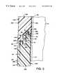
- FIG. 4is a cross-sectional view illustrating an insulated building panel according to the present invention.
- FIG. 4 ais a perspective, isolated view of a face sheet and gutter having one type of aperture disposed therein;
- FIG. 4 bis substantially the same view as FIG. 4 a but illustrating another type of aperture
- FIG. 4 cis substantially the same view as FIG. 4 a but illustrating yet another type of aperture
- FIG. 4 dis substantially the same view of FIG. 3, but illustrating an aperture arrangement through the structural foam core
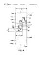
- FIG. 5is substantially the same view as FIG. 4, but illustrating a “mid-hook” face sheet attachment
- FIG. 6is substantially the same view as FIG. 4, but illustrating a narrower reveal width
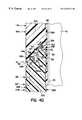
- FIG. 7is substantially the same view as FIGS. 4 and 6, but showing a greater reveal width
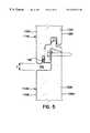
- FIG. 8is substantially the same view as FIG. 4, but illustrating an upper panel of greater depth than the lower panel;
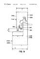
- FIG. 9is substantially the same view as FIG. 4, but illustrating a lower panel of greater depth than the upper panel;
- FIG. 10is substantially the same view as FIG. 4, but illustrating upper and lower panels of greater depth than those shown in FIG. 4;
- FIG. 11is substantially the same view as FIG. 4, but illustrating a reveal of customizably varying width
- FIG. 11Aillustrates a conventional registration block arrangement used in the formation of building panels
- FIG. 11Billustrates a registration block arrangement in accordance with an embodiment of the present invention
- FIG. 12illustrates a building wall portion that includes both foam panels and profiled sheet metal panels
- FIG. 13is a close-up cross-sectional view taken from FIG. 12, and illustrating a connection between a profiled panel and a foam panel;
- FIG. 14is a close-up cross-sectional view taken from FIG. 12, and illustrating a connection between two profiled panels.
- FIG. 15is a close-up cross-sectional view taken from FIG. 12, and illustrating a connection between two foam panels.
- FIGS. 1-3are taken from U.S. Pat. No. 5,749,282 (Brow et al.) for the purpose of illustrating conventional horizontal joinery, and associated components, having aspects that might be utilized in accordance with at least one presently preferred embodiment of the present invention.
- the same patentis fully incorporated by reference into this specification, in order that further conventional details forming the background and/or environment of at least one presently preferred embodiment of the present invention may be relied upon as needed.
- FIG. 1there is illustrated an exterior wall structure 10 supported on a structural framework including vertical columns 12 .
- the wall structure 10is assembled from individual panels 14 having adjacent panel ends 16 , 18 forming a vertical joint 20 and being connected along the lower and upper side edges 22 , 24 to form horizontal wall joint 26 .
- the insulated building panel 14comprises inner and outer facing sheets 28 , 30 and a structural foam core 32 filling the interior space of the building panel 14 and adhesively connecting the facing sheets 28 , 30 to provide a structural panel.
- the inner and outer facing sheets 28 , 30provide inner and outer male connectors or tongues 34 , 36 .
- the inner and outer facing sheets 28 , 30provide inner and outer female connectors 38 , 40 adapted to receive the tongues 34 , 36 of a subjacent building panel. As is illustrated FIG.
- the inner and outer female connectors 38 , 40each receive a bead 42 , 44 of sealant, such as a non-hardening butyl sealant.
- sealantsuch as a non-hardening butyl sealant.
- the beads 42 , 44 of sealantare adapted to be penetrated by the tongues 34 , 36 of a subjacent panel to form inner and outer seals as shown in FIG. 3 .
- gutter means 45is provided at the upper edge 22 of the building panel 14 and intermediate of the inner and outer tongues 34 , 36 .
- the gutter meansextends substantially entirely along the full length of the building panel 14 .
- the gutter meansserves to eliminate liquids bypassing the outer joint formed between the female connector 40 and the tongue of 36 of a subjacent building panels.
- the gutter means 45has a generally U-shaped transverse profile including upstanding sides 46 , 48 and a web of 50 connecting the sides 46 , 48 .
- the side 48 of the gutter means 45also constitutes a portion of the tongue 36 . Therefore, the gutter means 45 is formed, in part, by the outer male connector tongue 36 .
- FIG. 3there is illustrated a horizontal joint 26 between upper and lower panels 14 A, 14 B. Comparing FIGS. 2 and 3, it will be observed that the location of the upper edge 22 may be varied, as shown at 22 ′ and 22 ′′, and thus the width of the horizontal joint 26 may be varied as shown at 26 ′ and 26 ′′.
- the lower building panel 14is secured to the column 12 by a clip 56 and a fastener 58 .
- the clipincludes a downturned central flange at 60 penetrating the foam core 32 B and engaging the inner facing sheet 28 B and a pair of inclined flanges 62 , only one visible in FIG.
- the clip 56also has a main flange portion 64 which overlies the upstanding side 46 of the outer facing sheet 30 B.
- the fastener 58extends through the main flange portion 64 , the upstanding side 46 , the foam core 32 B, the inner facing sheets 28 B and into the vertical column 12 . In this manner, both the inner and outer facing sheets 28 B, 30 B of the panel 14 B are secured to the vertical column 12 .
- FIGS. 4-7components that are substantially analogous to components in FIGS. 1-3 have been so indicated by advancing the reference numerals by 100.
- FIG. 4is a cross-sectional view illustrating an insulated building panel according to at least one presently preferred embodiment of the present invention.
- thermal break 190In addition to the conventional components illustrated in FIGS. 1-3 (whose reference numerals have been advanced here by 100), also illustrated are thermal break 190 , reveal 192 , aperture(s) (or weep hole[s]) 194 , sloped shelf 196 and edge-hook connection 198 .
- Thermal break 190indicated with dotted lines at upper panel 114 A, merely constitutes a gap between outer face sheet 130 A (often termed simply a “face sheet”) and inner face sheet 128 A (often termed a “liner” or “liner sheet”), wherein a portion of the foam core 132 A is exposed.
- a similar thermal breakexists on lower panel 114 B, not numbered but indicated with dotted lines between outer face sheet 130 B and inner face sheet 128 B.
- foam core 132 A/ 132 Bessentially represents only one type of core material that can be utilized in a composite building panel (or structural panel).
- core materialsuch as a conventional honeycomb core structure.
- Indicated at 192is what is known in the art as a reveal, or, in the context of a building wall assembly, an indentation that is recessed into the wall assembly.
- reveal 192is defined between upper panel 114 A and lower panel 114 B.
- a revealprovides an enhanced visual effect on the outer side of a building wall assembly.
- revealstend to be shallow, that is, of limited dimension in a direction defined orthogonally between the outer side of the wall assembly and the inner side.
- “depth” or “thickness”may be defined as that dimension oriented horizontally with respect to FIG. 4, while the dimension perpendicular thereto in FIG. 4, oriented vertically, may be defined as “width”.
- the present inventionin accordance with at least one presently preferred embodiment, broadly contemplates a reveal 192 that is considerably deeper than the norm. Surprisingly, it has been found that such a reveal provides an enhanced visual effect from the outside and, further, that it is easier to fabricate and install corner panels, and connections therebetween, having such a reveal. Additionally, any repairs that are located within the reveal are essentially hidden to passersby because of the depth of the reveal. Such repairs might include, but are not limited to, those that are undertaken when forming a corner joint, particularly, when, subsequent to cutting a V-notch in the panels to be used at a corner and bending the panels, plate or sheet material is provided at the seam where the V-notch was cut.
- the depth of the revealis indicated as the dimension x in FIG. 4 .
- this dimensionwill be no less than about 0.75 inch.
- dimension xis 1.25 inches, while the depth of both panels 114 A and 114 B is 2 inches.
- a sloped shelf 196may preferably be provided within reveal 192 .
- the shelf 196will be sloped at about three degrees. Conventionally, slopes of five degrees have been encountered.
- arrow 194illustrates the presence of one or more apertures through face sheet 130 B, and at the bottom of gutter 145 , through which liquid present in the gutter 145 may exit the gutter 145 .
- One or more such aperturesmay preferably be distributed throughout the length (i.e. in a direction perpendicular to the plane of the drawing) of gutter 145 .
- one such aperturemay be present about every 12 inches along the length of gutter 145 .
- the location and distribution of the aperture(s)will be chosen in such a manner as to drain liquid from the gutter, and also to equalize pressure within the gutter, most efficiently and effectively.
- FIGS. 4 a- 4 cillustrate, in isolated perspective view, a lower panel face sheet 130 B, where this forms gutter 145 , with different types of apertures that might be utilized in accordance with at least one presently preferred embodiment of the present invention.
- FIG. 4 aillustrates a bottom aperture 194 a , which may be disposed in a lowermost or bottom portion of gutter 145 .
- FIG. 4 billustrates an “edge notch” aperture 194 b, which may be disposed in a portion of gutter 145 that is away from an end corner 145 C of gutter 145 .
- FIG. 4 cillustrates a “corner notch” aperture 194 c that is disposed right at an end corner 145 C of gutter 145 .
- the end corner 145 Cmay essentially be located at a corresponding end of the corresponding panel. If the gutter 145 does not feed into a vertical discharge channel (see the patent to Brow et al.) and instead terminates, at the illustrated end, at a gasket or other solid member that does not permit the onward horizontal flow of liquid beyond the gutter end, it will be appreciated that the liquid will then be discharged out through the corner notch 145 c.
- FIGS. 4 a- 4 cThe types of apertures illustrated in FIGS. 4 a- 4 c are provided as examples only, and are not intended in any way to limit the scope of the present invention.
- the aperture or apertures in questionis/are disposed intermediately with respect to the opposing ends of the gutter, in contrast or in addition to arrangements in which the gutters open at their ends to vertical discharge channels, as described in the patent to Brow et al.
- the present inventionalso contemplates, in accordance with at least one presently preferred embodiment, an arrangement in which the one or more apertures being used are not disposed to direct liquid flow from what are essentially lowermost portions of gutter 145 , as illustrated in FIGS. 4 a- 4 c, but are disposed at somewhat higher points of the gutter wall that faces outwardly.
- liquidwill accumulate within the gutter and will discharge from the aperture(s) once the liquid level within the gutter matches the level of the aperture(s).
- the present inventioncontemplates such an arrangement particularly in conjunction with the use of vertical discharge channels, as discussed in the patent to Brow et al.
- the aperture(s) presently contemplatedcan serve the purpose of overflow drainage, in the event that the normal drainage through the gutter end(s) to the vertical discharge channels is backed up or inhibited for any reason.
- a deep reveal 192may be utilized in conjunction with the aperture(s) 194 just described.
- the reveal 192may preferably be defined partly by a sloped shelf 196 .
- Such a sloped shelfwill preferably assist considerably in diverting any liquid emanating from apertures 194 out of the reveal 192 .
- the sloped shelf 196also serves to divert away liquid from external sources, such as rain that is blown into the reveal 192 by the wind that enters reveal 192 by washing down the external face of the building wall assembly.
- the shallow slope discussed heretoforepreferably of about three degrees, has been found to be quite adequate for affording drainage away from the reveal 192 .
- reveal 192will have a predetermined width y. A manner of customizing this width will be discussed further below. In the embodiment illustrated in FIG. 4, if it is assumed that the overall depth of the panel structure is about 2 inches, then dimension y, the width of the reveal 192 , is illustrated as being 1 ⁇ 2 inch, which is recognized throughout the industry as a standard width.
- aperture(s) 194 dmay proceed from gutter means 45 B, through foam core 32 B, and may exit through an opening in face sheet 30 B. It will thus be appreciated that the present invention contemplates not only the use of one or more apertures in conjunction with a deep reveal that permits immediate egress of liquid from an internal gutter arrangement to the outside, but also in conjunction with a structural panel containing a foam or other core, such as the panel 14 B shown in FIG.
- aperture(s) 194 dmay actually tunnel through the foam or other core in a suitable manner in order to facilitate the egress of liquid from an internal gutter arrangement.
- aperture(s) 194 dmay actually tunnel through the foam or other core in a suitable manner in order to facilitate the egress of liquid from an internal gutter arrangement.
- such an arrangement of aperture(s)could be provided instead of or in addition to the types of vertical discharge channels that are described in the patent to Brow et al.
- FIG. 5illustrates a “mid-hook” 199 in place of the edge-hook 198 of FIG. 4 .
- Mid-hook 199in FIG. 5, is preferably formed as a crimped, intermediate portion of face sheet 130 B, configured for extending upwardly into a corresponding pocket in upper panel 114 A.
- FIGS. 6 and 7represent substantially similar views as FIG. 4, but illustrate, respectively, a narrower reveal width and a greater reveal width. Particularly, if it is assumed that the overall depth of the panel structure is about 2 inches in each case, then dimension y, the width of the reveal 192 , is illustrated as being 1 ⁇ 8 inch in FIG. 6 and 2 inches in FIG. 7 . As will be described further below, the present invention contemplates, in accordance with at least one presently preferred embodiment, the possibility of customizing dimension y in a unique manner.
- FIGS. 8-10components that are substantially analogous to components in FIGS. 1-3 have been so indicated by advancing the reference numerals by 200.
- FIG. 8illustrates an example in which upper panel 214 A has a notably greater overall depth (or thickness) z than the overall depth (or thickness) a of lower panel 214 B.
- dimension ais equal to about 2 inches while dimension z is equal to about 2.75 inches.
- dimension xis still equal to about 1.25 inches.
- FIG. 9illustrates an example in which upper panel 214 A has a notably smaller overall depth z than the overall depth a of lower panel 214 B.
- dimension ais equal to about 2.75 inches while dimension z is equal to about 2 inches.
- dimension x, or the greatest depth of the revealis equal to about 2 inches.
- the proportion represented by the greatest reveal depth x with respect to the depth a of the lower panelhas thus increased to about ⁇ fraction (8/11) ⁇ , or about 0.727.
- FIG. 10illustrates an example in which upper panel 214 A has the same, larger overall depth z as the overall depth a of lower panel 214 B.
- dimension ais equal to about 2.75 inches while dimension z is also equal to about 2.75 inches.
- Dimension x, or the greatest depth of the revealis again equal to about 2 inches, and the proportion represented by the greatest reveal depth x with respect to the depth a of the lower panel is again ⁇ fraction (8/11) ⁇ , or 0.727.
- FIGS. 8-10illustrate a measure of versatility, in assembling wall assemblies, afforded by at least one presently preferred embodiment of the present invention. In each case, it is possible to maintain a significantly deep reveal, with the attendant advantages described heretofore.
- an upper bent portion 298 of lower outer face sheet 230 Bmay preferably be so configured and designed as to mate adequately with a corresponding recessed portion of upper outer face sheet 230 A.
- the bent portion 298is in the form of a “J-hook”, but could also be configured as a “mid-hook” as shown in FIG. 11 .
- the present inventionbroadly contemplates, in accordance with at least one presently preferred embodiment, the facilitated interchangeable assembly of various upper panels 214 A and lower panels 214 B of differing depths, whereas conventionally this might have been difficult and cumbersome in view of differing and incompatible connection schemes.
- the “J-hook” 298 shown in FIGS. 8-10could be realized in two discrete pieces, as opposed to the single piece shown. Thus, one smaller piece would be constituted only by the J-shaped portion. In this manner, the tight 180-degree bend illustrated in FIGS. 8-10 would be eliminated.
- the separate J-hook 298 Acould be formed from a lighter gauge material, such as stainless steel or aluminum.
- a separate J-hookmight be desirable for other reasons, as determined by the dictates of the user.
- FIGS. 8-10can be utilized in the context of vertically-oriented panels, as opposed to horizontally-oriented panels.
- FIGS. 8-10can be interpreted as plan, rather than elevational, views and that the connection between panels 214 A and 214 B can be construed as a vertical joint, rather than a horizontal joint.
- the inclusion of aperture(s) 294does not necessarily detract from the use of panels 214 A and 214 B in a vertical orientation, as they could conceivably assist in serving the purpose of pressure equalization, especially if internal gutter 245 does not lead to orthogonally oriented external channels at either of its ends.
- FIG. 11components that are substantially analogous to components in to FIGS. 1-3 have been so indicated by advancing the reference numerals by 300 .
- FIG. 11illustrates an arrangement in which the width (i.e., the dimension y shown in earlier drawings) of reveal 392 can be customized.
- the widthi.e., the dimension y shown in earlier drawings
- FIG. 11illustrates an arrangement in which the width (i.e., the dimension y shown in earlier drawings) of reveal 392 can be customized.
- an optional drip edge 396is also shown in FIG. 11 .
- suitable toolingmay be utilized to quickly and efficiently change over an appropriate forming apparatus, such as a roll-forming apparatus, from one configuration, in which one given reveal width is produced, to another configuration, in which another given reveal width is produced. It is believed that this type of versatile customization would be of great benefit to manufacturers who would wish to cater, at short notice, to the divergent requests of one or more customers as regards the width of a reveal.
- reveal widthsfrom about 1 ⁇ 8′′ to greater than about 2′′ (such us up to about 6′′) are possible, such as in increments of about 1 ⁇ 4′′.
- FIG. 11Aillustrates a conventional registration block (or side rail) arrangement typically utilized subsequent to the roll-forming of face sheets for building panels.
- registration blocksare used to hold face sheets in an accurate positional relationship prior to, and during, the application of an insulative material, such as foam, between the face sheets.
- block 402may include, among other things, a first end face 404 and a second end face 406 .
- first end face 404is configured for engaging with that portion 405 a of an inner face sheet 405 (e.g., similar to sheet 328 B shown in FIG. 11) that has been bent at one end of inner face sheet 328 B.
- second end face 406is configured for engaging with that portion 408 a of an outer face sheet 408 (e.g., similar to sheet 330 B shown in FIG. 11) that forms the lower part of a reveal (such as reveal 392 shown in FIG. 11 ).
- an outer face sheet 408e.g., similar to sheet 330 B shown in FIG. 11
- a revealsuch as reveal 392 shown in FIG. 11
- the engagement of a registration block with face sheetstakes place once the face sheets have already been roll-formed, or formed in some other manner, for the purpose of positioning and aligning the face sheets with respect to one another in preparation for the injection or insertion of the desired core material between the face sheets.
- the foamis typically injected into the cavity between the two face sheets (once registered via the registration block), and the registration block typically assists in preventing the foam from inadvertently leaking from this cavity during the injection process.
- registration block 402in connection with the conventional example shown in FIG. 11A, provides registration at two significant points, namely the aforementioned “bend” portion 405 a of an inner face sheet 405 and the lower “reveal” portion 408 a of an outer face sheet 408 .
- a disadvantage that has often been encountered with the type of registration block illustrated in FIG. 11Ais that essentially only one predetermined and fixed reveal width can be accommodated. Particularly, since that portion of the outer face sheet defining the lower limit of the reveal is used in registration, then only one reveal width, as defined by the formation of the same portion of the outer face sheet, can essentially only be introduced to the corresponding registration block. In the industry, it is well-known that such registration blocks are expensive items to purchase and install. Thus, the capacity for customizable formation with different reveal widths is severely hampered, as a different registration block is essentially required for each different reveal width that is introduced.
- FIG. 11Billustrates a registration arrangement, according to at least one presently preferred embodiment of the present invention, that is configured to accept outer face sheets that result in different reveal widths.
- a registration block 452may include a first face 454 and a second face 456 .
- the first face 454will preferably be configured as to engage with that portion 455 a of an inner face sheet 455 (e.g., similar to sheet 328 B shown in FIG. 11) that has been bent at one end of inner face sheet 455 .
- the second end face 456is preferably configured for engaging not with a portion of an outer face sheet 458 (e.g., similar to sheet 330 B shown in FIG. 11) that forms the lower part of a reveal (such as reveal 392 shown in FIG.
- registration block 452provides registration at two significant points that are different from the significant points encountered by the registration block 402 shown in FIG. 11 A.
- the significant pointsare the aforementioned “bend” portion 455 a of an inner face sheet 455 and the “upper” reveal portion 458 a of an outer face sheet 458 .
- FIG. 11Bcan lend itself admirably to a forming apparatus in which a roll-forming unit and a foam injection unit (or a unit otherwise dedicated to the introduction of an insulative material) are included in the same assembly line, so that sheets that have been roll-formed can progress automatically to a registration block for the subsequent introduction of insulative material.
- a registration arrangementsuch as that shown in FIG. 11B, it will be possible to change reveal widths quickly and efficiently, perhaps even on the fly.
- FIGS. 12-15any components that might be substantially analogous to components in FIGS. 1-3 have not necessarily been advanced by a multiple of 100 as has been done in FIGS. 4-11.
- FIG. 12illustrates a general wall assembly 500 having composite structural panels, such as foam panels, 501 along with decorative profile panels 503 .
- decorative profile panels 503are formed from sheet metal and may contain therewithin some form of insulation and, as shown, may also contain decorative or otherwise aesthetically significant features, such as the types of indentations shown in FIG. 12 .
- connection schemeIndicated at 513 is a first connection scheme, to be described and illustrated in more detail with respect to FIG. 13 .
- 514indicates a second connection scheme, corresponding to FIG. 14, whilst 515 indicates a third connection scheme, corresponding to FIG. 15 .
- these three types of connection schemesare of such a nature that they afford the easy and customizable interchanging and intermingling of structural panels 501 and profile panels 503 .
- a profile panel 503is connected atop a structural panel 501 .
- structural panel 501includes a structural foam core that is flanked by outer face sheet (or simply “face sheet”) 518 and inner face sheet(or “inner” or “liner sheet”) 519 , respectively.
- Indicated at 520is a “J-hook” extension of outer face sheet 518 .
- a reveal 522may be defined between the upper, profile panel 503 and the lower, structural panel 501 .
- a suitable attachment mechanism 524such as a bolt, may be used to hold firmly a clip 526 .
- This clip 526may include legs 528 and 530 , the former extending into the structural foam core 516 and the latter extending upwardly into a nook or bend formed in inner face sheet 519 .
- a suitable sealant or sealing arrangement 532may be provided between panels 503 and 501 .
- Upper profile panel 503itself preferably contains outer and inner facing (or face) sheets 534 and 536 , respectively.
- outer face sheet 534At the lower end of outer face sheet 534 , there is preferably a bent terminal portion 535 that serves as a receptacle for the “J-hook” portion 520 of outer face sheet 518 of lower structural panel 501 .
- a sheet of insulation 538may preferably be provided within profile panel 503 .
- FIG. 14a first profile panel 503 a is connected atop a second profile panel 503 b. Similar reference numerals, indicating similar components, have been retained from FIG. 13, with the addition of “a” or “b” to indicate components in panels 503 a and 503 b, respectively.
- the outer face sheet 518 b of lower panel 503 bmay include an intricately bent end portion 540 configured for mating with the lower bent portion 535 of the outer face sheet 518 a of upper panel 503 a.
- a clip 544attached to insulation sheet 538 b with a suitable attachment device, such as a bolt, 543 , may preferably be configured for accommodating part of bent end portion 540 . Also, it may preferably have a splayed upper end, as shown, to accommodate a bent upper portion of inner face sheet 536 b of lower panel 503 b.
- a suitable sealant or sealing arrangement 532 ′is preferably provided.
- FIG. 15a structural panel 501 is connected atop a profile panel 503 . Similar reference numerals, indicating similar components, have been retained from FIG. 13 .
- a clip 546may preferably be utilized with attachment devices (such as bolts) 548 and 550 that extend into and/or through insulation sheet 538 .
- An adapter clip 552extending from the attachment point of attachment device 550 with clip 546 , may preferably be configured to extend into the recess created by lower bent portion 535 of structural panel 501 .
- each of the panelswill preferably be configured so as to easily and interchangeably accommodate either a profile panel or a structural panel, at most with only minor modification.
- profile panelshave tended to be formed in rather singular manner at their connectable ends. It will thus be appreciated that, in accordance with at least one presently preferred embodiment of the present invention, such panels will preferably undergo at their ends such artificial formation as to be fully integrable with either another profile panel or a structural panel.
- a profile panelis adaptively configured so as to be able to mate with a structural building panel in such a manner as to mimic essentially the same physical characteristics, and associated advantages, normally found in a connection between two structural building panels.
- the inner face sheets in questionwill preferably be realized in such a manner as to result in the establishment of a consistent barrier, with consistent sealing, against vapor pressure, air infiltration and water infiltration.
- the present inventioncontemplates the inclusion of such sheets in a manner that essentially mimics the manner in which they are realized in structural panels.
- the upper and lower panels in each case, be they structural or profile panelsexhibit similar physical and operational characteristics.
- the liner sheets of the upper and lower panelswill exhibit coplanarity as in an interconnection between structural panels (see, for example, FIG. 4 ).
- a factory-installed seal(e.g., such as indicated at 532 and 532 ′) is normally supplemented, in the context of adjacent structural panels, by a field-installed seal.
- the field-installed sealnormally abuts the liner sheets on the building side of the wall assembly, and will normally migrate into cavities between the upper and lower panels so as to “meet” the factory-installed seal.
- Such a sealing arrangementprovides very favorable protection against air, vapor and water infiltration.
- a profile panelwill mimic several characteristics of a structural panel, a similar advantage will be encountered here.
- material from a field-installed sealwill preferably migrate into a cavity 533 (as shown in each of FIGS. 13-15) between upper and lower panels, resulting in the same advantages as just described.
- any and all of the building panels, and interconnections, illustrated and described hereinmay be utilized either in a horizontal configuration or in a vertical configuration.
- the structures and components described and illustrated herein in connection with at least one presently preferred embodiment of the present inventionare applicable not only to the context of horizontal panels connected by horizontal joints but also to the context of vertical panels connected by vertical joints.
- a deep revealoffers several unique features.
- the depth of revealallows it to perform as a pressure equalized pocket, possibly in addition to an internal pressure equalized pocket (such as may be afforded by an internally disposed gutter), while allowing venting of the panel, such as along the entire length of the panel.
- the depthalso creates a reveal with a bolder aesthetic appearance, which is known to be preferred by some designers.
- the deep revealcan be more easily fabricated into corner panels than shallow reveals. Bent or folded corner panels are the most common applications in this regard.
- Vertical joints created at the ends of horizontal panelscan be treated in several ways. First, they can be filled with opened extruded gasketry, which will allow water to drain from the enclosed joint pocket to the vertical joint. Second, a solid closed-cell foam gasket can be used to keep water out of the vertical joint.
- the method of joint design as presentedwill allow the engagement of multiple panel thickness. For example, a thick panel can be engaged to a thin panel and vice versa. This is accomplished by having a common top edge of panel regardless of thickness. (See FIGS. 8 - 10 ).
- the inventive jointcan be used in either a horizontal or vertical orientation. This will be helpful in allowing fewer changeovers.
Landscapes
- Engineering & Computer Science (AREA)
- Architecture (AREA)
- Civil Engineering (AREA)
- Structural Engineering (AREA)
- Finishing Walls (AREA)
- Conveying And Assembling Of Building Elements In Situ (AREA)
Abstract
Description
Claims (26)
Priority Applications (9)
| Application Number | Priority Date | Filing Date | Title |
|---|---|---|---|
| US09/196,050US6253511B1 (en) | 1998-11-19 | 1998-11-19 | Composite joinery |
| CA002351846ACA2351846C (en) | 1998-11-19 | 1999-09-30 | Composite joinery |
| EP99951689AEP1131509A1 (en) | 1998-11-19 | 1999-09-30 | Composite joinery |
| PCT/US1999/022810WO2000031357A1 (en) | 1998-11-19 | 1999-09-30 | Composite joinery |
| MXPA01004994AMXPA01004994A (en) | 1998-11-19 | 1999-09-30 | Composite joinery. |
| AU64077/99AAU6407799A (en) | 1998-11-19 | 1999-11-09 | Composite joinery |
| US09/656,057US6627128B1 (en) | 1998-11-19 | 2000-09-06 | Composite joinery |
| US09/794,569US6968659B2 (en) | 1998-11-19 | 2001-02-27 | Composite joinery |
| US09/794,653US20010004816A1 (en) | 1998-11-19 | 2001-02-27 | Composite joinery |
Applications Claiming Priority (1)
| Application Number | Priority Date | Filing Date | Title |
|---|---|---|---|
| US09/196,050US6253511B1 (en) | 1998-11-19 | 1998-11-19 | Composite joinery |
Related Child Applications (3)
| Application Number | Title | Priority Date | Filing Date |
|---|---|---|---|
| US09/656,057DivisionUS6627128B1 (en) | 1998-11-19 | 2000-09-06 | Composite joinery |
| US09/794,653DivisionUS20010004816A1 (en) | 1998-11-19 | 2001-02-27 | Composite joinery |
| US09/794,569DivisionUS6968659B2 (en) | 1998-11-19 | 2001-02-27 | Composite joinery |
Publications (1)
| Publication Number | Publication Date |
|---|---|
| US6253511B1true US6253511B1 (en) | 2001-07-03 |
Family
ID=22723937
Family Applications (4)
| Application Number | Title | Priority Date | Filing Date |
|---|---|---|---|
| US09/196,050Expired - LifetimeUS6253511B1 (en) | 1998-11-19 | 1998-11-19 | Composite joinery |
| US09/656,057Expired - LifetimeUS6627128B1 (en) | 1998-11-19 | 2000-09-06 | Composite joinery |
| US09/794,569Expired - LifetimeUS6968659B2 (en) | 1998-11-19 | 2001-02-27 | Composite joinery |
| US09/794,653AbandonedUS20010004816A1 (en) | 1998-11-19 | 2001-02-27 | Composite joinery |
Family Applications After (3)
| Application Number | Title | Priority Date | Filing Date |
|---|---|---|---|
| US09/656,057Expired - LifetimeUS6627128B1 (en) | 1998-11-19 | 2000-09-06 | Composite joinery |
| US09/794,569Expired - LifetimeUS6968659B2 (en) | 1998-11-19 | 2001-02-27 | Composite joinery |
| US09/794,653AbandonedUS20010004816A1 (en) | 1998-11-19 | 2001-02-27 | Composite joinery |
Country Status (6)
| Country | Link |
|---|---|
| US (4) | US6253511B1 (en) |
| EP (1) | EP1131509A1 (en) |
| AU (1) | AU6407799A (en) |
| CA (1) | CA2351846C (en) |
| MX (1) | MXPA01004994A (en) |
| WO (1) | WO2000031357A1 (en) |
Cited By (37)
| Publication number | Priority date | Publication date | Assignee | Title |
|---|---|---|---|---|
| US20020020130A1 (en)* | 2000-08-10 | 2002-02-21 | Nichiha Co.,Ltd. | Sealing member and siding boards attachment structure |
| EP1279777A1 (en)* | 2001-07-27 | 2003-01-29 | Talfab Holdings Limited | Composite panels |
| US6634077B2 (en) | 2001-07-20 | 2003-10-21 | Affordable Building Systems | Combined connecting and alignment method for composite fiber building panels |
| US6637728B2 (en)* | 2000-06-29 | 2003-10-28 | Gsw Inc. | Plastic privacy fence |
| US20040134143A1 (en)* | 2003-01-14 | 2004-07-15 | Centria | Features for thin composite architectural panels |
| US20060156671A1 (en)* | 2005-01-20 | 2006-07-20 | Robert Montague | Apparatus and method for aligning and connecting building panels in close proximity |
| US20060174577A1 (en)* | 2005-01-27 | 2006-08-10 | O'neil John P | Hidden stiffening panel connector and connecting method |
| US20070107358A1 (en)* | 2005-10-07 | 2007-05-17 | Damon Stone | Concrete tile system and method of manufacture |
| US20080000176A1 (en)* | 2006-06-26 | 2008-01-03 | Barry Mandelzys | Insulated panel system |
| US20080029209A1 (en)* | 2006-08-07 | 2008-02-07 | Centria | Segmented composite panel with false joints and method for making the same |
| EP2025855A2 (en) | 2007-08-15 | 2009-02-18 | Advanced Glazing Technologies Limited (AGTL) | Interlocking structural glazing panels |
| US20090193742A1 (en)* | 2008-02-06 | 2009-08-06 | Wolf David H | Prefabricated wall panel with tongue and groove construction |
| US20090260311A1 (en)* | 2008-04-18 | 2009-10-22 | Centria | Extruded Seal Plate For Horizontal Insulated Composite Architectural Panel Vertical End Joints |
| US7748181B1 (en) | 2006-01-20 | 2010-07-06 | Centria | Advanced building envelope delivery system and method |
| US20100170173A1 (en)* | 2006-01-20 | 2010-07-08 | Centria | Advanced building envelope delivery system and method |
| US20110173922A1 (en)* | 2010-01-18 | 2011-07-21 | Boral Stone Products Llc | Trim kit for building construction |
| US20110214372A1 (en)* | 2010-03-08 | 2011-09-08 | William Mullet | Insulated siding apparatus |
| US20110252731A1 (en)* | 2010-04-20 | 2011-10-20 | Centria | Drained and Back Ventilated Thin Composite Wall Cladding System |
| USD667963S1 (en) | 2011-03-31 | 2012-09-25 | Firestone Building Products Company, Llc | Wall panel |
| USD668353S1 (en) | 2011-03-31 | 2012-10-02 | Firestone Building Products Company, Llc | Wall panel |
| USD668357S1 (en) | 2011-03-31 | 2012-10-02 | Firestone Building Products Company, Llc | Wall panel |
| USD668354S1 (en) | 2011-03-31 | 2012-10-02 | Firestone Building Products Company, Llc | Wall panel |
| USD668356S1 (en) | 2011-03-31 | 2012-10-02 | Firestone Building Products Company, Llc | Wall panel |
| USD670009S1 (en) | 2011-01-18 | 2012-10-30 | Boral Stone Products Llc | Trim kit for building construction |
| US8621810B2 (en) | 2011-02-28 | 2014-01-07 | Kingspan Insulated Panels, Inc. (USA) | Building wall system |
| US8661756B2 (en) | 2010-04-20 | 2014-03-04 | Centria | Insulated metal vertical joint insert |
| US8813451B2 (en)* | 2011-07-19 | 2014-08-26 | Red Glaze Group, LLC | Wall attachment clip, wall panel system, and system and method for supporting wall panels |
| US8938927B1 (en)* | 2014-06-18 | 2015-01-27 | McElroy Metal Mill, Inc. | Horizontally oriented insulated metal panel siding system |
| US9027302B2 (en) | 2012-08-08 | 2015-05-12 | Boral Stone Products, LLC | Wall panel |
| US9499978B2 (en) | 2012-10-03 | 2016-11-22 | Kingspan Insulated Panels, Inc. | Building wall panel |
| US9938725B2 (en) | 2015-05-04 | 2018-04-10 | Kingspan Insulated Panels, Inc. | Building panel |
| US10246882B2 (en)* | 2015-11-10 | 2019-04-02 | Kong Taing | Structural wall panel system |
| US11230845B2 (en)* | 2018-02-07 | 2022-01-25 | Kwang Steel Co., Ltd. | Building exterior panel and assembly structure thereof |
| US11293188B2 (en) | 2020-01-03 | 2022-04-05 | C.E.I. Composite Materials, Inc. | Architectural wall panel system |
| US11332943B2 (en) | 2019-10-08 | 2022-05-17 | D.A. Distribution Inc. | Wall covering with adjustable spacing |
| US11396749B2 (en) | 2020-01-21 | 2022-07-26 | Mitek Holdings, Inc. | Exterior wall system |
| US20230113988A1 (en)* | 2021-10-08 | 2023-04-13 | Nucor Insulated Panel Group LLC., a Nucor Company | Wall panel clip |
Families Citing this family (70)
| Publication number | Priority date | Publication date | Assignee | Title |
|---|---|---|---|---|
| US6425626B1 (en)* | 2001-01-04 | 2002-07-30 | Michael Kloepfer | Truck/trailer box constructions |
| DE10101202B4 (en)* | 2001-01-11 | 2007-11-15 | Witex Ag | parquet board |
| EP1392501A1 (en)* | 2001-06-06 | 2004-03-03 | Kingspan Research and Developments Limited | An insulated panel |
| GB0210336D0 (en)* | 2002-05-04 | 2002-06-12 | Metex Flooring Systems Ltd | Non slip sealed stainless steel flooring tiles |
| ES2302394B2 (en) | 2003-11-19 | 2009-07-28 | British Robertson, S.L.U. | PANEL WITH MACHIHEMBRATED REMATES FOR FACADES OR COVERS. |
| CA2492185A1 (en)* | 2004-01-08 | 2005-07-08 | Tecton Products | Pultruded building product |
| US6988761B1 (en)* | 2004-02-23 | 2006-01-24 | Brian Stidham | Interlocking channeled trailer side panels with integrated sliding outer panel inserts |
| US20050262791A1 (en)* | 2004-05-17 | 2005-12-01 | Todd Pringle | Siding and building product |
| US7520099B2 (en)* | 2004-05-17 | 2009-04-21 | Tecton Products | Pultruded building product and system |
| USD523780S1 (en) | 2004-08-10 | 2006-06-27 | Mac Trailer Manufacturing, Inc. | Combined trailer construction member and joint |
| US20060059791A1 (en)* | 2004-08-10 | 2006-03-23 | Conny Michael A | Trailer construction and joint for use therewith |
| US20060096217A1 (en)* | 2004-11-05 | 2006-05-11 | Lance Philip A | Cladding |
| US7178860B2 (en)* | 2005-04-22 | 2007-02-20 | Vantage Trailers, Inc. | Trailer having reduced weight wall construction |
| US7338111B2 (en)* | 2005-09-09 | 2008-03-04 | Vantage Trailers, Inc. | Trailer having combination extruded panel/sheet sides |
| DE102006006124A1 (en)* | 2006-02-10 | 2007-08-23 | Flooring Technologies Ltd. | Device for locking two building panels |
| US20080209836A1 (en)* | 2006-04-13 | 2008-09-04 | Huber Engineered Woods Llc | Contained Load Transfer Device for Wood Sheathing Products and Roof Construction Method Therewith |
| US20070261353A1 (en)* | 2006-05-10 | 2007-11-15 | Cullen Leslie D | Insulative siding apparatus and method of making the same |
| US8176701B2 (en)* | 2006-05-10 | 2012-05-15 | Cullen Leslie D | Insulative siding apparatus and method of making the same |
| US20080143142A1 (en)* | 2006-12-01 | 2008-06-19 | Vantage Trailers, Inc. | Trailer With Double Wall Extruded Panel Nose Construction |
| EP2140078A1 (en)* | 2007-04-18 | 2010-01-06 | Kingspan Research and Developments Limited | A cladding panel |
| US7856790B2 (en)* | 2007-10-10 | 2010-12-28 | Tecton Products, Llc | Pultruded building product |
| US20090293407A1 (en)* | 2008-06-02 | 2009-12-03 | Lief Eric Swanson | Building exterior panels and method |
| US7954292B2 (en) | 2008-09-12 | 2011-06-07 | Progressive Foam Technologies, Inc. | Insulated siding system |
| US20100236171A1 (en)* | 2009-03-18 | 2010-09-23 | Liu David C | Preinstalled glue system for floor |
| US20100236173A1 (en)* | 2009-03-19 | 2010-09-23 | Sergiy Pacha | System of Wall Facings |
| DE102009035528B4 (en)* | 2009-07-31 | 2014-12-24 | R&M Kühllagerbau Holding GmbH | cold storage |
| US8635828B2 (en)* | 2010-01-13 | 2014-01-28 | Pacific Insulated Panel Llc | Composite insulating building panel and system and method for attaching building panels |
| US8291672B2 (en) | 2010-01-15 | 2012-10-23 | Mitek Holdings, Inc. | Anchor system for composite panel |
| CA2742046C (en)* | 2010-06-04 | 2014-04-29 | Progressive Foam Technologies, Inc. | Insulation system |
| CA2825421C (en)* | 2011-02-09 | 2016-04-26 | Kingspan Research And Developments Limited | A composite insulation panel |
| US20120225236A1 (en)* | 2011-03-03 | 2012-09-06 | James Edward Cox | Composite Building Panel and Method |
| US9476202B2 (en) | 2011-03-28 | 2016-10-25 | Owens Corning Intellectual Capital Llc | Foam board with pre-applied sealing material |
| CA2809080C (en) | 2012-03-14 | 2017-03-07 | Mitek Holdings, Inc. | Mounting arrangement for panel veneer structures |
| US8800241B2 (en) | 2012-03-21 | 2014-08-12 | Mitek Holdings, Inc. | Backup wall reinforcement with T-type anchor |
| US8904730B2 (en) | 2012-03-21 | 2014-12-09 | Mitek Holdings, Inc. | Thermally-isolated anchoring systems for cavity walls |
| US8739485B2 (en) | 2012-06-28 | 2014-06-03 | Mitek Holdings, Inc. | Low profile pullout resistant pintle and anchoring system utilizing the same |
| US8839581B2 (en) | 2012-09-15 | 2014-09-23 | Mitek Holdings, Inc. | High-strength partially compressed low profile veneer tie and anchoring system utilizing the same |
| US8898980B2 (en) | 2012-09-15 | 2014-12-02 | Mitek Holdings, Inc. | Pullout resistant pintle and anchoring system utilizing the same |
| US8881488B2 (en) | 2012-12-26 | 2014-11-11 | Mitek Holdings, Inc. | High-strength ribbon loop anchors and anchoring systems utilizing the same |
| US9038351B2 (en) | 2013-03-06 | 2015-05-26 | Columbia Insurance Company | Thermally coated wall anchor and anchoring systems with in-cavity thermal breaks for cavity walls |
| US8863460B2 (en) | 2013-03-08 | 2014-10-21 | Columbia Insurance Company | Thermally coated wall anchor and anchoring systems with in-cavity thermal breaks |
| US8833003B1 (en) | 2013-03-12 | 2014-09-16 | Columbia Insurance Company | High-strength rectangular wire veneer tie and anchoring systems utilizing the same |
| US8978326B2 (en) | 2013-03-12 | 2015-03-17 | Columbia Insurance Company | High-strength partition top anchor and anchoring system utilizing the same |
| US8910445B2 (en) | 2013-03-13 | 2014-12-16 | Columbia Insurance Company | Thermally isolated anchoring system |
| US8844229B1 (en) | 2013-03-13 | 2014-09-30 | Columbia Insurance Company | Channel anchor with insulation holder and anchoring system using the same |
| US9260857B2 (en) | 2013-03-14 | 2016-02-16 | Columbia Insurance Company | Fail-safe anchoring systems for cavity walls |
| US20140262073A1 (en)* | 2013-03-15 | 2014-09-18 | Steve Timmons | Product Using Multiple Slats |
| US8904726B1 (en) | 2013-06-28 | 2014-12-09 | Columbia Insurance Company | Vertically adjustable disengagement prevention veneer tie and anchoring system utilizing the same |
| US9121169B2 (en) | 2013-07-03 | 2015-09-01 | Columbia Insurance Company | Veneer tie and wall anchoring systems with in-cavity ceramic and ceramic-based thermal breaks |
| US8978330B2 (en) | 2013-07-03 | 2015-03-17 | Columbia Insurance Company | Pullout resistant swing installation tie and anchoring system utilizing the same |
| US9038350B2 (en) | 2013-10-04 | 2015-05-26 | Columbia Insurance Company | One-piece dovetail veneer tie and wall anchoring system with in-cavity thermal breaks |
| US8904727B1 (en) | 2013-10-15 | 2014-12-09 | Columbia Insurance Company | High-strength vertically compressed veneer tie anchoring systems utilizing and the same |
| US20150218808A1 (en)* | 2014-02-05 | 2015-08-06 | Steve Bates | Thermal breaks within a structure with integrated insulation |
| US20200248443A1 (en)* | 2019-02-06 | 2020-08-06 | Steve Bates | Structure with integrated insulation |
| US20150218821A1 (en)* | 2014-02-05 | 2015-08-06 | Steve Bates | Attachment components for securing portions of a structure with integrated insulation to one another |
| US20150218810A1 (en)* | 2014-02-05 | 2015-08-06 | Steve Bates | Panel junction attachments for use in a structure with integrated insulation |
| US9140001B1 (en) | 2014-06-24 | 2015-09-22 | Columbia Insurance Company | Thermal wall anchor |
| US9334646B2 (en) | 2014-08-01 | 2016-05-10 | Columbia Insurance Company | Thermally-isolated anchoring systems with split tail veneer tie for cavity walls |
| US9574341B2 (en)* | 2014-09-09 | 2017-02-21 | Romeo Ilarian Ciuperca | Insulated reinforced foam sheathing, reinforced elastomeric vapor permeable air barrier foam panel and method of making and using same |
| US9273461B1 (en) | 2015-02-23 | 2016-03-01 | Columbia Insurance Company | Thermal veneer tie and anchoring system |
| US10407892B2 (en) | 2015-09-17 | 2019-09-10 | Columbia Insurance Company | High-strength partition top anchor and anchoring system utilizing the same |
| USD846973S1 (en) | 2015-09-17 | 2019-04-30 | Columbia Insurance Company | High-strength partition top anchor |
| US10738475B2 (en) | 2015-10-30 | 2020-08-11 | Boral Ip Holdings (Australia) Pty Limited | Wall panel with rain screen |
| US20170159285A1 (en) | 2015-12-04 | 2017-06-08 | Columbia Insurance Company | Thermal wall anchor |
| ITUA20162682A1 (en)* | 2016-04-18 | 2017-10-18 | Renato Marchesi | REMOVABLE COVERING DEVICE |
| CA3154821A1 (en)* | 2017-01-25 | 2018-08-02 | Luigi PALLADINO | Cladding panel |
| WO2018200599A2 (en) | 2017-04-24 | 2018-11-01 | Ayo-Ap Corporation | Water draining spandrel assembly and insulated panel window walls |
| CN107327073A (en)* | 2017-08-15 | 2017-11-07 | 多维联合集团有限公司 | A kind of double interlocking splicing type metal curtain wallboard and curtain wall |
| US10590659B2 (en)* | 2018-04-05 | 2020-03-17 | 888804 Ontario Limited | Pre-finished insulated panel system for cladding a building |
| USD1074521S1 (en)* | 2024-06-28 | 2025-05-13 | Richard Leslie Williamson | Utility trailer floor panel |
Citations (17)
| Publication number | Priority date | Publication date | Assignee | Title |
|---|---|---|---|---|
| US3120082A (en) | 1961-09-06 | 1964-02-04 | Bernard E Mendelsohn | Siding |
| US3158960A (en) | 1961-09-22 | 1964-12-01 | Building Products Ltd | Siding panels |
| US3246436A (en) | 1963-01-09 | 1966-04-19 | Alan D Roush | Siding and roofing panel |
| US3740909A (en) | 1971-02-25 | 1973-06-26 | Du Pont Canada | Preformed building panel with weather proof seal |
| US3797190A (en) | 1972-08-10 | 1974-03-19 | Smith E Division Cyclops Corp | Prefabricated, insulated, metal wall panel |
| US4114335A (en) | 1974-04-04 | 1978-09-19 | Carroll Research, Inc. | Sheet metal structural shape and use in building structures |
| US4123885A (en) | 1976-04-30 | 1978-11-07 | Cyclops Corporation | Building panel joint |
| US4184301A (en) | 1977-08-27 | 1980-01-22 | H. H. Robertson Company | Fastening device for wall panel joints |
| US4320613A (en) | 1979-05-17 | 1982-03-23 | Alside, Inc. | Profiled insulating underboard |
| EP0110265A2 (en) | 1982-11-30 | 1984-06-13 | METECNO S.p.A. | A process for continuously producing two-faced self-supporting sandwich panels having an interposed layer of insulating material and provided with continuous substantially rigid side joints, and panels obtained |
| US4685263A (en)* | 1986-05-23 | 1987-08-11 | Ting Raymond M L | Aluminum plate curtain wall structure |
| US4751125A (en) | 1985-07-27 | 1988-06-14 | Duropal-Werk Eberh. Wrede Gmbh & Co. Kg | Composite panel having a drip groove |
| DE9205931U1 (en) | 1992-05-07 | 1992-08-20 | Heinemann, Herbert, 7530 Pforzheim | Cladding element |
| GB2262791A (en) | 1991-12-27 | 1993-06-30 | Perfil En Frio Sa | Connection for the edges of facing panels |
| US5425210A (en) | 1992-08-07 | 1995-06-20 | Zafir; George | Insulated panel |
| US5749282A (en) | 1995-06-29 | 1998-05-12 | United Dominion Industries | Building panel with double interlock joint and internal gutter |
| US5916100A (en)* | 1997-12-12 | 1999-06-29 | ? Elward Systems Corporation | Method and apparatus for erecting wall panels |
Family Cites Families (17)
| Publication number | Priority date | Publication date | Assignee | Title |
|---|---|---|---|---|
| US2264546A (en)* | 1939-10-09 | 1941-12-02 | Carbide & Carbon Chem Corp | Surface covering and assembly thereof |
| NO97816A (en)* | 1959-01-16 | |||
| US4034528A (en)* | 1976-06-18 | 1977-07-12 | Aegean Industries, Inc. | Insulating vinyl siding |
| US4327528A (en)* | 1980-02-29 | 1982-05-04 | Wolverine Aluminum Corporation | Insulated siding system |
| US4918879A (en)* | 1987-05-29 | 1990-04-24 | Commercial And Architectural Products, Inc. | Merchandising wall structure including readily attachable and detachable panels and having plastic reveals |
| US4765107A (en)* | 1987-10-19 | 1988-08-23 | Ting Raymond M L | Vertical joint sealing of horizontal wall panels |
| US4924647A (en)* | 1989-08-07 | 1990-05-15 | E. G. Smith Construction Products Inc. | Exterior wall panel drainage system |
| FR2651517B1 (en)* | 1989-09-04 | 1992-03-20 | Felix Andre | FACADE COMPRISING AN EXTERIOR GLASS SCREEN. |
| US5293728A (en) | 1992-09-17 | 1994-03-15 | Texas Aluminum Industries, Inc. | Insulated panel |
| US5452552A (en)* | 1993-03-18 | 1995-09-26 | Ting; Raymond M. L. | Leakproof framed panel curtain wall system |
| US5509242A (en) | 1994-04-04 | 1996-04-23 | American International Homes Limited | Structural insulated building panel system |
| US5497589A (en) | 1994-07-12 | 1996-03-12 | Porter; William H. | Structural insulated panels with metal edges |
| US5617682A (en) | 1995-06-07 | 1997-04-08 | Texas Aluminum Industries, Inc. | Insulated skylight panel |
| US5694735A (en)* | 1995-12-19 | 1997-12-09 | Lovas; Gary | Method and a tool for crimping a tee or main |
| US5867964A (en)* | 1995-12-20 | 1999-02-09 | Perrin; Arthur | Prefabricated construction panels and modules for multistory buildings and method for their use |
| US6122877A (en)* | 1997-05-30 | 2000-09-26 | Andersen Corporation | Fiber-polymeric composite siding unit and method of manufacture |
| US6018924A (en)* | 1997-08-21 | 2000-02-01 | Tamlyn; John Thomas | Adjustable reveal strip and related method of construction |
- 1998
- 1998-11-19USUS09/196,050patent/US6253511B1/ennot_activeExpired - Lifetime
- 1999
- 1999-09-30EPEP99951689Apatent/EP1131509A1/ennot_activeWithdrawn
- 1999-09-30WOPCT/US1999/022810patent/WO2000031357A1/ennot_activeApplication Discontinuation
- 1999-09-30MXMXPA01004994Apatent/MXPA01004994A/enactiveIP Right Grant
- 1999-09-30CACA002351846Apatent/CA2351846C/ennot_activeExpired - Lifetime
- 1999-11-09AUAU64077/99Apatent/AU6407799A/ennot_activeAbandoned
- 2000
- 2000-09-06USUS09/656,057patent/US6627128B1/ennot_activeExpired - Lifetime
- 2001
- 2001-02-27USUS09/794,569patent/US6968659B2/ennot_activeExpired - Lifetime
- 2001-02-27USUS09/794,653patent/US20010004816A1/ennot_activeAbandoned
Patent Citations (17)
| Publication number | Priority date | Publication date | Assignee | Title |
|---|---|---|---|---|
| US3120082A (en) | 1961-09-06 | 1964-02-04 | Bernard E Mendelsohn | Siding |
| US3158960A (en) | 1961-09-22 | 1964-12-01 | Building Products Ltd | Siding panels |
| US3246436A (en) | 1963-01-09 | 1966-04-19 | Alan D Roush | Siding and roofing panel |
| US3740909A (en) | 1971-02-25 | 1973-06-26 | Du Pont Canada | Preformed building panel with weather proof seal |
| US3797190A (en) | 1972-08-10 | 1974-03-19 | Smith E Division Cyclops Corp | Prefabricated, insulated, metal wall panel |
| US4114335A (en) | 1974-04-04 | 1978-09-19 | Carroll Research, Inc. | Sheet metal structural shape and use in building structures |
| US4123885A (en) | 1976-04-30 | 1978-11-07 | Cyclops Corporation | Building panel joint |
| US4184301A (en) | 1977-08-27 | 1980-01-22 | H. H. Robertson Company | Fastening device for wall panel joints |
| US4320613A (en) | 1979-05-17 | 1982-03-23 | Alside, Inc. | Profiled insulating underboard |
| EP0110265A2 (en) | 1982-11-30 | 1984-06-13 | METECNO S.p.A. | A process for continuously producing two-faced self-supporting sandwich panels having an interposed layer of insulating material and provided with continuous substantially rigid side joints, and panels obtained |
| US4751125A (en) | 1985-07-27 | 1988-06-14 | Duropal-Werk Eberh. Wrede Gmbh & Co. Kg | Composite panel having a drip groove |
| US4685263A (en)* | 1986-05-23 | 1987-08-11 | Ting Raymond M L | Aluminum plate curtain wall structure |
| GB2262791A (en) | 1991-12-27 | 1993-06-30 | Perfil En Frio Sa | Connection for the edges of facing panels |
| DE9205931U1 (en) | 1992-05-07 | 1992-08-20 | Heinemann, Herbert, 7530 Pforzheim | Cladding element |
| US5425210A (en) | 1992-08-07 | 1995-06-20 | Zafir; George | Insulated panel |
| US5749282A (en) | 1995-06-29 | 1998-05-12 | United Dominion Industries | Building panel with double interlock joint and internal gutter |
| US5916100A (en)* | 1997-12-12 | 1999-06-29 | ? Elward Systems Corporation | Method and apparatus for erecting wall panels |
Cited By (83)
| Publication number | Priority date | Publication date | Assignee | Title |
|---|---|---|---|---|
| US6637728B2 (en)* | 2000-06-29 | 2003-10-28 | Gsw Inc. | Plastic privacy fence |
| US6609342B2 (en)* | 2000-08-10 | 2003-08-26 | Nichiha Co., Ltd. | Sealing member and siding boards attachment structure |
| US20020020130A1 (en)* | 2000-08-10 | 2002-02-21 | Nichiha Co.,Ltd. | Sealing member and siding boards attachment structure |
| US6634077B2 (en) | 2001-07-20 | 2003-10-21 | Affordable Building Systems | Combined connecting and alignment method for composite fiber building panels |
| GB2378191B (en)* | 2001-07-27 | 2005-05-18 | Talfab Holdings Ltd | Composite panels |
| EP1279777A1 (en)* | 2001-07-27 | 2003-01-29 | Talfab Holdings Limited | Composite panels |
| US7007433B2 (en) | 2003-01-14 | 2006-03-07 | Centria | Features for thin composite architectural panels |
| WO2004065715A1 (en)* | 2003-01-14 | 2004-08-05 | Centria | Features for thin composite architectural panels |
| US20070039275A1 (en)* | 2003-01-14 | 2007-02-22 | Keith Boyer | Features for thin composite architectural panels |
| US20040134143A1 (en)* | 2003-01-14 | 2004-07-15 | Centria | Features for thin composite architectural panels |
| US20060156671A1 (en)* | 2005-01-20 | 2006-07-20 | Robert Montague | Apparatus and method for aligning and connecting building panels in close proximity |
| US20060174577A1 (en)* | 2005-01-27 | 2006-08-10 | O'neil John P | Hidden stiffening panel connector and connecting method |
| US20070107358A1 (en)* | 2005-10-07 | 2007-05-17 | Damon Stone | Concrete tile system and method of manufacture |
| US8631620B2 (en) | 2006-01-20 | 2014-01-21 | Centria | Advanced building envelope delivery system and method |
| US9027301B2 (en) | 2006-01-20 | 2015-05-12 | Centria | Advanced building envelope delivery system and method |
| US20100170173A1 (en)* | 2006-01-20 | 2010-07-08 | Centria | Advanced building envelope delivery system and method |
| US7748181B1 (en) | 2006-01-20 | 2010-07-06 | Centria | Advanced building envelope delivery system and method |
| US20080000176A1 (en)* | 2006-06-26 | 2008-01-03 | Barry Mandelzys | Insulated panel system |
| US20100115884A1 (en)* | 2006-08-07 | 2010-05-13 | Centria | Segmented Composite Panel with False Joints |
| US20080029209A1 (en)* | 2006-08-07 | 2008-02-07 | Centria | Segmented composite panel with false joints and method for making the same |
| US7895807B2 (en) | 2006-08-07 | 2011-03-01 | Centria | Segmented composite panel with false joints |
| US7678219B2 (en) | 2006-08-07 | 2010-03-16 | Centria | Method for making segmented composite panel with false joints |
| US8028479B2 (en) | 2007-08-15 | 2011-10-04 | Advanced Glazing Technologies Limited (Agtl) | Interlocking structural glazing panels |
| EP2025855A2 (en) | 2007-08-15 | 2009-02-18 | Advanced Glazing Technologies Limited (AGTL) | Interlocking structural glazing panels |
| US20090064608A1 (en)* | 2007-08-15 | 2009-03-12 | Advanced Glazing Technologies Limited (Agtl) | Interlocking Structural Glazing Panels |
| US8782988B2 (en) | 2008-02-06 | 2014-07-22 | Boral Stone Products Llc | Prefabricated wall panel with tongue and groove construction |
| US20090193742A1 (en)* | 2008-02-06 | 2009-08-06 | Wolf David H | Prefabricated wall panel with tongue and groove construction |
| US11891814B2 (en) | 2008-02-06 | 2024-02-06 | Westlake Royal Stone Llc | Prefabricated wall panel with tongue and groove construction |
| US10557273B2 (en) | 2008-02-06 | 2020-02-11 | Boral Stone Products Llc | Prefabricated wall panel with tongue and groove construction |
| US10378216B2 (en) | 2008-02-06 | 2019-08-13 | Boral Stone Products Llc | Prefabricated wall panel with tongue and groove construction |
| US10329775B2 (en) | 2008-02-06 | 2019-06-25 | Boral Ip Holdings (Australia) Pty Limited | Method of forming a wall panel |
| US9903124B2 (en) | 2008-02-06 | 2018-02-27 | Boral Stone Products Llc | Prefabricated wall panel with tongue and groove construction |
| US8474202B2 (en) | 2008-04-18 | 2013-07-02 | Centria | Extruded seal plate for horizontal insulated composite architectural panel vertical end joints |
| US8261499B2 (en) | 2008-04-18 | 2012-09-11 | Centria | Extruded seal plate for horizontal insulated composite architectural panel vertical end joints |
| US20090260311A1 (en)* | 2008-04-18 | 2009-10-22 | Centria | Extruded Seal Plate For Horizontal Insulated Composite Architectural Panel Vertical End Joints |
| US20110173922A1 (en)* | 2010-01-18 | 2011-07-21 | Boral Stone Products Llc | Trim kit for building construction |
| US8387325B2 (en)* | 2010-03-08 | 2013-03-05 | Provia Products | Insulated siding apparatus |
| US20110214372A1 (en)* | 2010-03-08 | 2011-09-08 | William Mullet | Insulated siding apparatus |
| US20110252731A1 (en)* | 2010-04-20 | 2011-10-20 | Centria | Drained and Back Ventilated Thin Composite Wall Cladding System |
| US8661756B2 (en) | 2010-04-20 | 2014-03-04 | Centria | Insulated metal vertical joint insert |
| USD674920S1 (en) | 2011-01-18 | 2013-01-22 | Boral Stone Products Llc | Trim kit for building construction |
| USD670009S1 (en) | 2011-01-18 | 2012-10-30 | Boral Stone Products Llc | Trim kit for building construction |
| US8984833B2 (en) | 2011-02-28 | 2015-03-24 | Kingspan Insulated Panels, Inc. | Building wall system |
| US8621810B2 (en) | 2011-02-28 | 2014-01-07 | Kingspan Insulated Panels, Inc. (USA) | Building wall system |
| USD733328S1 (en) | 2011-03-31 | 2015-06-30 | Firestone Building Products Company, Llc | Wall panel |
| USD677403S1 (en) | 2011-03-31 | 2013-03-05 | Firestone Building Products Company, Llc | Wall panel |
| USD690442S1 (en) | 2011-03-31 | 2013-09-24 | Firestone Building Products Company, Llc | Wall panel |
| USD698046S1 (en) | 2011-03-31 | 2014-01-21 | Firestone Building Products Company, Llc | Wall panel |
| USD687977S1 (en) | 2011-03-31 | 2013-08-13 | Firestone Building Products Company, Llc | Wall panel |
| USD698944S1 (en) | 2011-03-31 | 2014-02-04 | Firestone Building Products Company, Llc | Wall panel |
| USD698946S1 (en) | 2011-03-31 | 2014-02-04 | Firestone Building Products Company, Llc | Wall panel |
| USD698947S1 (en) | 2011-03-31 | 2014-02-04 | Firestone Building Products Company, Llc | Wall panel |
| USD700364S1 (en) | 2011-03-31 | 2014-02-25 | Firestone Building Products Company, Llc | Wall panel |
| USD700365S1 (en) | 2011-03-31 | 2014-02-25 | Firestone Building Products Company, Llc | Wall panel |
| USD700366S1 (en) | 2011-03-31 | 2014-02-25 | Firestone Building Products Company, Llc | Wall panel |
| USD679834S1 (en) | 2011-03-31 | 2013-04-09 | Firestone Building Products Company, Llc | Wall panel |
| USD677404S1 (en) | 2011-03-31 | 2013-03-05 | Firestone Building Products Company, Llc | Wall panel |
| USD667963S1 (en) | 2011-03-31 | 2012-09-25 | Firestone Building Products Company, Llc | Wall panel |
| USD668353S1 (en) | 2011-03-31 | 2012-10-02 | Firestone Building Products Company, Llc | Wall panel |
| USD677402S1 (en) | 2011-03-31 | 2013-03-05 | Firestone Building Products Company, Llc | Wall panel |
| USD687976S1 (en) | 2011-03-31 | 2013-08-13 | Firestone Building Products Company, Llc | Wall panel |
| USD668357S1 (en) | 2011-03-31 | 2012-10-02 | Firestone Building Products Company, Llc | Wall panel |
| USD690838S1 (en) | 2011-03-31 | 2013-10-01 | Firestone Building Products Company, Llc | Wall panel |
| USD732701S1 (en) | 2011-03-31 | 2015-06-23 | Firestone Building Products Company, Llc | Wall panel |
| USD668356S1 (en) | 2011-03-31 | 2012-10-02 | Firestone Building Products Company, Llc | Wall panel |
| USD736953S1 (en) | 2011-03-31 | 2015-08-18 | Firestone Building Products Company, Llc | Wall panel |
| USD668354S1 (en) | 2011-03-31 | 2012-10-02 | Firestone Building Products Company, Llc | Wall panel |
| USD733329S1 (en) | 2011-03-31 | 2015-06-30 | Firestone Building Products Company, Llc | Wall panel |
| US8813451B2 (en)* | 2011-07-19 | 2014-08-26 | Red Glaze Group, LLC | Wall attachment clip, wall panel system, and system and method for supporting wall panels |
| US9951517B2 (en) | 2011-07-19 | 2018-04-24 | Hgi Resources Llc | Wall attachment clip, wall panel system, and system and method for supporting wall panels |
| US9027302B2 (en) | 2012-08-08 | 2015-05-12 | Boral Stone Products, LLC | Wall panel |
| USRE47694E1 (en) | 2012-08-08 | 2019-11-05 | Boral Stone Products Llc | Wall panel |
| US9499978B2 (en) | 2012-10-03 | 2016-11-22 | Kingspan Insulated Panels, Inc. | Building wall panel |
| US8938927B1 (en)* | 2014-06-18 | 2015-01-27 | McElroy Metal Mill, Inc. | Horizontally oriented insulated metal panel siding system |
| US20180291635A1 (en)* | 2015-05-04 | 2018-10-11 | Kingspan Insulated Panels, Inc. | Building Panel |
| US9938725B2 (en) | 2015-05-04 | 2018-04-10 | Kingspan Insulated Panels, Inc. | Building panel |
| US10246882B2 (en)* | 2015-11-10 | 2019-04-02 | Kong Taing | Structural wall panel system |
| US11230845B2 (en)* | 2018-02-07 | 2022-01-25 | Kwang Steel Co., Ltd. | Building exterior panel and assembly structure thereof |
| US11332943B2 (en) | 2019-10-08 | 2022-05-17 | D.A. Distribution Inc. | Wall covering with adjustable spacing |
| US11293188B2 (en) | 2020-01-03 | 2022-04-05 | C.E.I. Composite Materials, Inc. | Architectural wall panel system |
| US11396749B2 (en) | 2020-01-21 | 2022-07-26 | Mitek Holdings, Inc. | Exterior wall system |
| US12000146B2 (en) | 2020-01-21 | 2024-06-04 | Mitek Holdings, Inc. | Exterior wall system |
| US20230113988A1 (en)* | 2021-10-08 | 2023-04-13 | Nucor Insulated Panel Group LLC., a Nucor Company | Wall panel clip |
Also Published As
| Publication number | Publication date |
|---|---|
| AU6407799A (en) | 2000-06-13 |
| CA2351846A1 (en) | 2000-06-02 |
| CA2351846C (en) | 2005-04-05 |
| WO2000031357A1 (en) | 2000-06-02 |
| US6627128B1 (en) | 2003-09-30 |
| US20010004816A1 (en) | 2001-06-28 |
| US6968659B2 (en) | 2005-11-29 |
| EP1131509A1 (en) | 2001-09-12 |
| MXPA01004994A (en) | 2006-02-22 |
| US20010009085A1 (en) | 2001-07-26 |
Similar Documents
| Publication | Publication Date | Title |
|---|---|---|
| US6253511B1 (en) | Composite joinery | |
| US20240263511A1 (en) | Window sill flashing | |
| US5725201A (en) | Adjustable width panel assembly | |
| CN100523398C (en) | Building panels | |
| US5245809A (en) | Urethane insulating panel and method | |
| US7526897B2 (en) | J-channel backer material | |
| US5713159A (en) | Multi part plastic lineal | |
| US20060191219A1 (en) | Glass block panel system and fabrication method of same | |
| EP3371387B1 (en) | Curtain wall mullions, transoms and systems | |
| US7121050B2 (en) | Fascias | |
| US4114345A (en) | Method for the production of houses | |
| JP3502832B2 (en) | Method for construction around opening at the time of renovation and decorative member around opening for use in construction method | |
| EP4050174B1 (en) | Concrete formwork system with insulating panels, connection elements and assembly method | |
| CN212359478U (en) | Window casing | |
| US20050097841A1 (en) | Glazing method | |
| US20080229690A1 (en) | Modular molding system and methods thereof | |
| US20020056240A1 (en) | Joint section positioned between flat, transparent filler elements, used particularly for internal partition wall structure | |
| EP0277226B1 (en) | Improved panel unit | |
| GB2360048A (en) | Fascia board connector | |
| ES3008024T3 (en) | Concrete formwork system with insulating panels, connection elements and assembly method | |
| CN211230009U (en) | Window frame and window sleeve | |
| AU712695B3 (en) | Concealed service ducting for insulated panels | |
| JP2024023732A (en) | architectural panels | |
| CA2506449C (en) | J-channel backer material | |
| GB2394483A (en) | Building panel |
Legal Events
| Date | Code | Title | Description |
|---|---|---|---|
| AS | Assignment | Owner name:CENTRIA, PENNSYLVANIA Free format text:ASSIGNMENT OF ASSIGNORS INTEREST;ASSIGNOR:BOYER, KEITH;REEL/FRAME:009606/0720 Effective date:19981118 | |
| AS | Assignment | Owner name:PNC BANK, NATIONAL ASSOCIATION, PENNSYLVANIA Free format text:SECURITY AGREEMENT;ASSIGNOR:CENTRIA;REEL/FRAME:013634/0340 Effective date:20020628 Owner name:PNC BANK, NATIONAL ASSOCIATION COMMERCIAL LOAN SER Free format text:;ASSIGNOR:CENTRIA;REEL/FRAME:013625/0925 Effective date:20020628 | |
| FPAY | Fee payment | Year of fee payment:4 | |
| SULP | Surcharge for late payment | ||
| FEPP | Fee payment procedure | Free format text:PETITION RELATED TO MAINTENANCE FEES GRANTED (ORIGINAL EVENT CODE: PMFG); ENTITY STATUS OF PATENT OWNER: LARGE ENTITY Free format text:PETITION RELATED TO MAINTENANCE FEES FILED (ORIGINAL EVENT CODE: PMFP); ENTITY STATUS OF PATENT OWNER: LARGE ENTITY | |
| REMI | Maintenance fee reminder mailed | ||
| REIN | Reinstatement after maintenance fee payment confirmed | ||
| FP | Lapsed due to failure to pay maintenance fee | Effective date:20090703 | |
| PRDP | Patent reinstated due to the acceptance of a late maintenance fee | Effective date:20091103 | |
| FPAY | Fee payment | Year of fee payment:8 | |
| STCF | Information on status: patent grant | Free format text:PATENTED CASE | |
| SULP | Surcharge for late payment | ||
| REMI | Maintenance fee reminder mailed | ||
| FPAY | Fee payment | Year of fee payment:12 | |
| SULP | Surcharge for late payment | Year of fee payment:11 | |
| AS | Assignment | Owner name:WELLS FARGO CAPITAL FINANCE, LLC, AS AGENT, GEORGI Free format text:NOTICE AND CONFIRMATION OF GRANT OF SECURITY INTEREST IN PATENTS;ASSIGNOR:CENTRIA;REEL/FRAME:034837/0116 Effective date:20150116 | |
| AS | Assignment | Owner name:CENTRIA, PENNSYLVANIA Free format text:RELEASE BY SECURED PARTY;ASSIGNOR:PNC BANK NATIONAL ASSOCIATION;REEL/FRAME:034830/0355 Effective date:20150116 | |
| AS | Assignment | Owner name:CREDIT SUISSE AG, CAYMAN ISLANDS BRANCH, NEW YORK Free format text:NOTICE AND CONFIRMATION OF GRANT OF SECURITY INTEREST IN PATENTS;ASSIGNOR:CENTRIA;REEL/FRAME:035715/0876 Effective date:20150116 | |
| AS | Assignment | Owner name:CENTRIA, PENNSYLVANIA Free format text:RELEASE BY SECURED PARTY;ASSIGNOR:PNC BANK NATIONAL ASSOCIATION;REEL/FRAME:043039/0266 Effective date:20170718 | |
| AS | Assignment | Owner name:NCI GROUP, INC., TEXAS Free format text:ASSIGNMENT OF ASSIGNORS INTEREST;ASSIGNOR:CENTRIA;REEL/FRAME:043151/0970 Effective date:20170626 | |
| AS | Assignment | Owner name:WELLS FARGO BANK, NATIONAL ASSOCIATION, AS COLLATE Free format text:SECURITY INTEREST;ASSIGNOR:NCI GROUP, INC.;REEL/FRAME:044873/0049 Effective date:20180208 | |
| AS | Assignment | Owner name:CENTRIA, TEXAS Free format text:RELEASE BY SECURED PARTY;ASSIGNOR:WELLS FARGO CAPITAL FINANCE, LLC, AS AGENT;REEL/FRAME:044898/0701 Effective date:20180208 Owner name:CREDIT SUISSE AG, CAYMAN ISLANDS BRANCH, AS COLLAT Free format text:SECURITY INTEREST;ASSIGNOR:NCI GROUP, INC.;REEL/FRAME:044902/0460 Effective date:20180208 Owner name:CENTRIA, TEXAS Free format text:TERMINATION AND RELEASE OF;ASSIGNOR:CREDIT SUISSE AG, CAYMAN ISLANDS BRANCH, AS ADMINISTRATIVE AGENT AND COLLATERAL AGENT;REEL/FRAME:045302/0930 Effective date:20180208 | |
| AS | Assignment | Owner name:NCI GROUP, INC., TEXAS Free format text:TERMINATION AND RELEASE OF SECURITY INTEREST IN PATENTS (ABL);ASSIGNOR:WELLS FARGO BANK, NATIONAL ASSOCIATION;REEL/FRAME:047588/0132 Effective date:20181116 Owner name:UBS AG, STAMFORD BRANCH, CONNECTICUT Free format text:ABL NOTICE AND CONFIRMATION OF GRANT OF SECURITY INTEREST IN PATENTS;ASSIGNORS:NCI GROUP, INC.;CENTRIA;REEL/FRAME:047588/0099 Effective date:20181116 Owner name:NCI GROUP, INC., TEXAS Free format text:TERMINATION AND RELEASE OF SECURITY INTERESTS IN PATENTS;ASSIGNOR:CREDIT SUISSE AG, CAYMAN ISLANDS BRANCH;REEL/FRAME:047588/0012 Effective date:20181116 Owner name:NCI GROUP, INC., TEXAS Free format text:TERMINATION AND RELEASE OF SECURITY INTEREST IN PATENTS (ABL);ASSIGNOR:WELLS FARGO BANK, NATIONAL ASSOCIATION;REEL/FRAME:047588/0121 Effective date:20181116 Owner name:JPMORGAN CHASE BANK, N.A., DELAWARE Free format text:CASH FLOW NOTICE AND CONFIRMATION OF GRANT OF SECURITY INTEREST IN PATENTS;ASSIGNORS:NCI GROUP, INC.;CENTRIA;REEL/FRAME:047587/0923 Effective date:20181116 | |
| AS | Assignment | Owner name:DEUTSCHE BANK AG NEW YORK BRANCH, AS SUCCESSOR COLLATERAL AGENT, NEW YORK Free format text:NOTICE OF SUCCESSION OF AGENCY;ASSIGNOR:JPMORGAN CHASE BANK, N.A.;REEL/FRAME:067461/0646 Effective date:20240515 |