US6252962B1 - Featureless covert communication system - Google Patents
Featureless covert communication systemDownload PDFInfo
- Publication number
- US6252962B1 US6252962B1US08/392,336US39233695AUS6252962B1US 6252962 B1US6252962 B1US 6252962B1US 39233695 AUS39233695 AUS 39233695AUS 6252962 B1US6252962 B1US 6252962B1
- Authority
- US
- United States
- Prior art keywords
- channel
- signal
- receiver
- reference signal
- transmitter
- Prior art date
- Legal status (The legal status is an assumption and is not a legal conclusion. Google has not performed a legal analysis and makes no representation as to the accuracy of the status listed.)
- Expired - Lifetime
Links
- 238000004891communicationMethods0.000titleclaimsabstractdescription29
- 238000000034methodMethods0.000claimsabstractdescription15
- 230000005540biological transmissionEffects0.000abstractdescription9
- 238000012545processingMethods0.000description11
- 230000002596correlated effectEffects0.000description5
- 238000001228spectrumMethods0.000description5
- 238000001514detection methodMethods0.000description4
- 230000001360synchronised effectEffects0.000description4
- 238000005291chaos (dynamical)Methods0.000description2
- DTSCLFDGIVWOGR-UHFFFAOYSA-N1,3-dimethyl-5h-pyrido[2,3]pyrrolo[2,4-b]pyrimidine-2,4-dioneChemical compoundC12=NC=CC=C2NC2=C1N(C)C(=O)N(C)C2=ODTSCLFDGIVWOGR-UHFFFAOYSA-N0.000description1
- 230000000739chaotic effectEffects0.000description1
- 238000013461designMethods0.000description1
- 238000003780insertionMethods0.000description1
- 230000037431insertionEffects0.000description1
- 230000003993interactionEffects0.000description1
- 230000003595spectral effectEffects0.000description1
Images

Classifications
- H—ELECTRICITY
- H04—ELECTRIC COMMUNICATION TECHNIQUE
- H04K—SECRET COMMUNICATION; JAMMING OF COMMUNICATION
- H04K1/00—Secret communication
- H04K1/10—Secret communication by using two signals transmitted simultaneously or successively
Definitions
- This inventionrelates to covert communication systems, i.e., a communication system in which the transmitted waveform exhibits no man-made detection features.
- DSPNdirect sequence pseudo-random noise
- Another covert communication techniqueis the use of a transmitted noise reference system. Under the transmitted noise reference system, two channels are broadcast: a reference noise channel and a data channel.
- the two transmitted signalssound and look like noise and are correlated at the receiver to extract the data or message signal.
- the reference noise channelIn order to achieve covert communication, the reference noise channel must be operated at levels below ambient noise. Because the receiver must work with a reference signal that has been corrupted by external noise, operating at these levels results in degraded performance. Under these conditions, signal processing time increases dramatically.
- synchronizationis first achieved between a covert transmitter and a covert receiver using two channels, one of which is a transmitted reference signal, then a single channel is used to transmit the bulk of the communication message.
- the single channeluses a digitally controlled noise source at both the transmitter and the receiver.
- the digitally controlled noise sourceproduces a signal having pre-selected and reproducible amplitude, frequency and phase components, which exhibit random noise like properties at both locations. Since only one channel is used to transmit the message, 3 dB in power is saved. And, since the same reference signal is being generated locally at the receiver, the efficiency of the system is improved by at least another 10 dB, and corruption of the reference signal is eliminated.
- the featureless covert communication systemoperates with signals that fall below the ambient noise levels and thus, even if intercepted, these signals should be confused with the normal occurrences of noise bursts in environment.
- transmission of the two channel reference subsystemis limited to short durations, typically less than one (1) second.
- a time delaycan be inserted into one channel at the transmitter and into the second channel at the receiver.
- Other featuressuch as encryption devices that are synchronized from a global positioning satellite system, can also be added to further enhance the system.
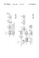
- FIG. 1shows the transmitter and receiver of the transmitted reference signal portion of a featureless covert communication system according to the invention.
- FIG. 2shows the transmitter and receiver of the message portion of a featureless covert communication system according to the invention.
- the objectives of covert communicationare generally achieved by first generating signals which fall below the ambient noise level in the intercept receiver, and second if, by chance, the intercept receiver is able to receive a clean signal, providing an “intercepted” signal that should be confused with the normal occurrences of noise bursts in the environment.
- Spread spectrum communication systemsgenerate wideband signals which fall below the ambient noise levels in most receivers.
- a transmission bandwidthis employed which is much greater than the bandwidth of the information to be communicated.
- the ratio of the transmission bandwidth to the information bandwidthis known as the processing gain.
- the objective in spread spectrum communication designis to develop processing gains that are extremely large without suffering the exponential increase in implementation complexities of higher and higher digital pseudorandom code rates in spread spectrum systems. Also, the depth with which the information signal may be buried below the noise level and still be recovered at the friendly receiver will be increased dramatically.
- Mimicking the normal occurrences of noise bursts in the environmentis achieved by using a transmitted waveform that is noise-like in all three characteristics: amplitude, frequency and phase, thus defeating feature detectors.
- a transmitted waveform having three noise-like componentsis achieved with a digitally controlled noise generator.
- a digitally controlled noise generatoruses a complex combination of noise generators, incorporating pre-selected amplitude, frequency and phase components, to give a precise and reproducible waveform.
- the DCNGproduces a signal which is not pure “random” noise as are produced by noise diodes.
- the noise produced by the DCNGcan be reproduced and controlled within nanosecond accuracies.
- Examples of digitally controlled noise generatorswhich may be used in the featureless covert communication system include a noise generator using Chaos theory as disclosed U.S. Pat. No. 5,048,086 entitled “Encryption System Based on Chaos Theory”, by M. Bianco et al. and U.S. Pat. No. 5,291,555 entitled “Communications Using Synchronized Chaotic Systems” by K. M. Cuomo et al.
- a transmitterat a first location
- a receiverat a second location
- the synchronization signalis encoded on one noise channel.
- the encoded noise channel and a noise reference signalare then transmitted. Both signals are detected at the receiver and correlated to determine the synchronization signal.
- the synchronization signal(or preamble) will identify the time at which the data or message signal will be sent.
- the synchronization signalmay also include other information, such as the data symbol period, a “barker” type code to establish a data start time, a receiver address and the data rate of the message.
- the receiversynchronizes to the transmitted signal with coarse resolution, the major time uncertainty of the transmission path between moving terminals is resolved. Then the data signal is transmitted using only a single channel. Since now only a single channel is being used, transmission power requirements are reduced on the order of three decibels. Thus, an intercept receiver of the radiometer type has less signal energy to detect.
- the data signalis encoded on the reference signal produced by a digitally controlled noise generator.
- the DCNGproduces a reference signal having pre-selected and reproducible amplitude, frequency and phase components which exhibit random noiselike properties.
- the transmittertransmits the data encoded reference signal which is detected at the receiver.
- the receiverincludes a DCNG which generates locally the same reference signal as the transmitter.
- the detected signal and locally generated reference signalare synchronized to the high resolution (nanosecond) state, through, for example, a slowing of the timing of the receiver DCNG, then correlated and demodulated to extract the data signal.
- the synchronization signalis transmitted only for a very short duration, preferably less than one (1) second. Also, since the reference signal produced by the DCNG at the receiver is a “clean” signal, an additional ten decibels in performance can be achieved at the friendly receiver.
- FIG. 1shows the transmitter and receiver of the transmitted reference signal subsystem.
- transmitter 10includes noise source 11 which generates a very wide bandwidth noise signal. This signal is filtered through bandpass filter 12 to make the signal more manageable.
- the noise signalthen is split in hybrid 13 into two channels, channel n and channel m.
- Channel nis then modulated in modulator 17 by synchronization signal 16 .
- Channels n and mare then amplified in amplifiers 19 and 20 , respectively before they are combined in hybrid combiner 21 .
- the combined signalsare then transmitted via antenna 22 .
- the transmitted signalsare received by antenna 31 of receiver 30 .
- the received signalsare amplified in low noise amplifier 32 before they are split into channels n and m.
- the received signals from mixer 33 and mixer 34are filtered through matched filters 35 and 36 , respectively to eliminate extraneous noise outside the signal passband.
- the outputsare then combined in phase detector 39 , integrated in integrator 40 and correlated in correlator 41 to yield the synchronization signal 42 .
- the purpose of the synchronization subsystemis to achieve synchronization between transmitter and receiver so that the lengthy data message can then be communicated. Once synchronization is achieved, the data message can be sent. To limit power requirements, only one channel is used.
- transmitter 40includes digitally controlled noise generator 41 to generate a reference signal having pre-selected and reproducible amplitude, frequency and phase components.
- the resulting precise waveformexhibits random noiselike properties.
- the reference signal from DCNG 41is then filtered through bandpass filter 43 before it is modulated by data signal 44 in modulator 45 .
- the modulated reference signalis then amplified in low band amplifier 46 before it is transmitted in antenna 47 .
- Receiver 50detects the signal from transmitter 40 in antenna 51 .
- the detected signalis amplified in amplifier 52 before it is converted in frequency in mixer 53 and filtered in matched filter 54 .
- Receiver 50also includes digitally controlled noise generator 55 which locally generates the same precise reference signal as transmitted by transmitter 40 .
- the locally generated reference signal from DCNG 55is filtered in matched filter 56 .
- the detected signal and the locally generated reference signalare correlated in multiple phase detectors 57 and multiple integrators 58 to extract the data signal 59 .
- High resolution (nonsecond) syncronizationis achieved through slowing control 62 . This slowing process can be completed, for example, through an exhaustive search of the order of 200 times states.
- noise source 11 and DCNG 41are the same digitally controlled noise generator in the transmitter (with appropriate switches to disconnect the second channel during data transmission).
- a single receiverwould include the digitally controlled noise generator 55 and switches to suitably connect it during data signal reception.
- channels A and Bneed not be transmitted side-by-side.
- Both transmitter and receivercan be designed to transmit and receive among several channels; i.e., to transmit and receive in two channels of a set of n equally likely channels psuedorandomly selected by a crypto device which is timed with GPS receivers.
- an additional crypto controlled psuedorandom variable parametermay be introduced.
- a controlled time delay 15is inserted in channel n of transmitter 10 .
- receiver 30would insert a compensating time delay 37 in its channel n to bring both channels into time alignment and then processing can take place.
- Use of the time delayimpedes the intercept receiver from performing its cross-correlation detections on a trial and error basis.
- both channels used in the synchronization signalwill experience similar doppler shifts due to platform movement.
- a sophisticated receivermay initiate a doppler tracking system based on the processing of signals in the two channels, but for most applications it would not be required during the preamble acquisition of the message.
- DCNGa locally generated noise source that is digitally controlled with precise timing.
- the DCNGmust accept digital presets to create unique starting points and have time accuracies of a few nanoseconds.
- the noise streamwould preferably be the result of the interaction of a number of pseudorandom digital codes with special processing controlled by an encryption device.
- the transmittermay lower its output power (in the example, from 17 decibels to 3 decibels).
- a resynchronization mechanismmay be required, depending on the stability of the DCNGs.
- the duration of the data transmissionis much greater than the preamble portion, it will not be detectable to an intercept receiver because of the vast difference in power levels.
- an encryption deviceset the parameters for the synchronization signal. Assuming the operating parameters (channel frequency and time delay) are set to change once an hour, these parameters are automatically selected based on the state of the encryption device at the terminal (for example, see encryption device 49 and 61 in FIG. 2 ).
- the state of the encryption deviceis, in time, based on the insertion of a local logical key and the time of day.
- the time of daywill be determined by a Global Positioning System (GPS) satellite, so that the “exact” time of operating parameter switch over may be determined.
- GPSGlobal Positioning System
- Timing and control 42would receive a time signal from a GPS satellite. Time resolution accuracies of 100 nanoseconds are relatively easy to achieve. Therefore, during any hour of the day, the uncertainty period for transmitter (receiver) settings will be of the order of 100 nanoseconds plus the time of flight for the radio signal between transmitter and receiver.
- encryption device 61After the transmitted reference preamble period of the message, encryption device 61 is used to establish the presets for DCNG 55 used during the data portion of the transmission. It should also be noted that frequency hopping techniques could be applied to the system.
Landscapes
- Engineering & Computer Science (AREA)
- Computer Networks & Wireless Communication (AREA)
- Signal Processing (AREA)
- Synchronisation In Digital Transmission Systems (AREA)
Abstract
Description
Claims (12)
Priority Applications (1)
| Application Number | Priority Date | Filing Date | Title |
|---|---|---|---|
| US08/392,336US6252962B1 (en) | 1994-04-22 | 1995-02-02 | Featureless covert communication system |
Applications Claiming Priority (2)
| Application Number | Priority Date | Filing Date | Title |
|---|---|---|---|
| US24136594A | 1994-04-22 | 1994-04-22 | |
| US08/392,336US6252962B1 (en) | 1994-04-22 | 1995-02-02 | Featureless covert communication system |
Related Parent Applications (1)
| Application Number | Title | Priority Date | Filing Date |
|---|---|---|---|
| US24136594AContinuation-In-Part | 1994-04-22 | 1994-04-22 |
Publications (1)
| Publication Number | Publication Date |
|---|---|
| US6252962B1true US6252962B1 (en) | 2001-06-26 |
Family
ID=22910433
Family Applications (1)
| Application Number | Title | Priority Date | Filing Date |
|---|---|---|---|
| US08/392,336Expired - LifetimeUS6252962B1 (en) | 1994-04-22 | 1995-02-02 | Featureless covert communication system |
Country Status (1)
| Country | Link |
|---|---|
| US (1) | US6252962B1 (en) |
Cited By (16)
| Publication number | Priority date | Publication date | Assignee | Title |
|---|---|---|---|---|
| US20030069026A1 (en)* | 2001-10-10 | 2003-04-10 | Hoctor Ralph Thomas | Ultra-wideband communications system and method using a delay hopped, continuous noise transmitted reference |
| US20030198212A1 (en)* | 2002-04-19 | 2003-10-23 | General Electric Company | Method and apparatus for synchronizing a radio telemetry system by way of transmitted-reference , delay-hopped ultra-wideband pilot signal |
| US20030228017A1 (en)* | 2002-04-22 | 2003-12-11 | Beadle Edward Ray | Method and system for waveform independent covert communications |
| US20040189525A1 (en)* | 2003-03-28 | 2004-09-30 | Beadle Edward R. | System and method for cumulant-based geolocation of cooperative and non-cooperative RF transmitters |
| US20040204878A1 (en)* | 2002-04-22 | 2004-10-14 | Anderson Richard H. | System and method for waveform classification and characterization using multidimensional higher-order statistics |
| US20040204922A1 (en)* | 2003-03-28 | 2004-10-14 | Beadle Edward Ray | System and method for hybrid minimum mean squared error matrix-pencil separation weights for blind source separation |
| US6993460B2 (en) | 2003-03-28 | 2006-01-31 | Harris Corporation | Method and system for tracking eigenvalues of matrix pencils for signal enumeration |
| US7715461B2 (en) | 1996-05-28 | 2010-05-11 | Qualcomm, Incorporated | High data rate CDMA wireless communication system using variable sized channel codes |
| CN101267293B (en)* | 2008-04-18 | 2011-03-30 | 清华大学 | Streaming Media Covert Communication Method Based on Hierarchical Model |
| CN108566260A (en)* | 2018-02-01 | 2018-09-21 | 西安电子科技大学 | It is a kind of based on the concealed communication method for disturbing point multiple access |
| CN110719126A (en)* | 2019-09-04 | 2020-01-21 | 南京理工大学 | A covert communication method suitable for MIMO communication system |
| EP3599781A1 (en)* | 2018-07-23 | 2020-01-29 | Nxp B.V. | Method for protecting a passive keyless entry system against a relay attack |
| CN111130594A (en)* | 2019-12-30 | 2020-05-08 | 华南理工大学 | Direct sequence spread spectrum-based heat hidden channel communication method |
| CN113194464A (en)* | 2021-04-26 | 2021-07-30 | 北京理工大学 | Internet of things physical layer covert communication method and device based on frequency spectrum detection |
| CN114157346A (en)* | 2022-02-08 | 2022-03-08 | 南京信息工程大学 | Cooperative backscatter covert communication system and communication method |
| CN116260540A (en)* | 2022-12-22 | 2023-06-13 | 西安电子科技大学 | A method of concealed signaling based on DRM digital broadcasting |
Citations (4)
| Publication number | Priority date | Publication date | Assignee | Title |
|---|---|---|---|---|
| US5007087A (en)* | 1990-04-16 | 1991-04-09 | Loral Aerospace Corp. | Method and apparatus for generating secure random numbers using chaos |
| US5048086A (en)* | 1990-07-16 | 1991-09-10 | Hughes Aircraft Company | Encryption system based on chaos theory |
| US5245660A (en)* | 1991-02-19 | 1993-09-14 | The United States Of America As Represented By The Secretary Of The Navy | System for producing synchronized signals |
| US5291555A (en)* | 1992-12-14 | 1994-03-01 | Massachusetts Institute Of Technology | Communication using synchronized chaotic systems |
- 1995
- 1995-02-02USUS08/392,336patent/US6252962B1/ennot_activeExpired - Lifetime
Patent Citations (4)
| Publication number | Priority date | Publication date | Assignee | Title |
|---|---|---|---|---|
| US5007087A (en)* | 1990-04-16 | 1991-04-09 | Loral Aerospace Corp. | Method and apparatus for generating secure random numbers using chaos |
| US5048086A (en)* | 1990-07-16 | 1991-09-10 | Hughes Aircraft Company | Encryption system based on chaos theory |
| US5245660A (en)* | 1991-02-19 | 1993-09-14 | The United States Of America As Represented By The Secretary Of The Navy | System for producing synchronized signals |
| US5291555A (en)* | 1992-12-14 | 1994-03-01 | Massachusetts Institute Of Technology | Communication using synchronized chaotic systems |
Cited By (27)
| Publication number | Priority date | Publication date | Assignee | Title |
|---|---|---|---|---|
| US8588277B2 (en) | 1996-05-28 | 2013-11-19 | Qualcomm Incorporated | High data rate CDMA wireless communication system using variable sized channel codes |
| US8213485B2 (en) | 1996-05-28 | 2012-07-03 | Qualcomm Incorporated | High rate CDMA wireless communication system using variable sized channel codes |
| US7715461B2 (en) | 1996-05-28 | 2010-05-11 | Qualcomm, Incorporated | High data rate CDMA wireless communication system using variable sized channel codes |
| US20030069026A1 (en)* | 2001-10-10 | 2003-04-10 | Hoctor Ralph Thomas | Ultra-wideband communications system and method using a delay hopped, continuous noise transmitted reference |
| US7068715B2 (en)* | 2001-10-10 | 2006-06-27 | Genral Electric Company | Ultra-wideband communications system and method using a delay hopped, continuous noise transmitted reference |
| US7313127B2 (en)* | 2002-04-19 | 2007-12-25 | General Electric Company | Method and apparatus for synchronizing a radio telemetry system by way of transmitted-reference, delay-hopped ultra-wideband pilot signal |
| US20030198212A1 (en)* | 2002-04-19 | 2003-10-23 | General Electric Company | Method and apparatus for synchronizing a radio telemetry system by way of transmitted-reference , delay-hopped ultra-wideband pilot signal |
| US20030228017A1 (en)* | 2002-04-22 | 2003-12-11 | Beadle Edward Ray | Method and system for waveform independent covert communications |
| US6711528B2 (en) | 2002-04-22 | 2004-03-23 | Harris Corporation | Blind source separation utilizing a spatial fourth order cumulant matrix pencil |
| US20040204878A1 (en)* | 2002-04-22 | 2004-10-14 | Anderson Richard H. | System and method for waveform classification and characterization using multidimensional higher-order statistics |
| US6993440B2 (en) | 2002-04-22 | 2006-01-31 | Harris Corporation | System and method for waveform classification and characterization using multidimensional higher-order statistics |
| US20040204922A1 (en)* | 2003-03-28 | 2004-10-14 | Beadle Edward Ray | System and method for hybrid minimum mean squared error matrix-pencil separation weights for blind source separation |
| US6993460B2 (en) | 2003-03-28 | 2006-01-31 | Harris Corporation | Method and system for tracking eigenvalues of matrix pencils for signal enumeration |
| US6931362B2 (en)* | 2003-03-28 | 2005-08-16 | Harris Corporation | System and method for hybrid minimum mean squared error matrix-pencil separation weights for blind source separation |
| US20040189525A1 (en)* | 2003-03-28 | 2004-09-30 | Beadle Edward R. | System and method for cumulant-based geolocation of cooperative and non-cooperative RF transmitters |
| US7187326B2 (en) | 2003-03-28 | 2007-03-06 | Harris Corporation | System and method for cumulant-based geolocation of cooperative and non-cooperative RF transmitters |
| CN101267293B (en)* | 2008-04-18 | 2011-03-30 | 清华大学 | Streaming Media Covert Communication Method Based on Hierarchical Model |
| CN108566260A (en)* | 2018-02-01 | 2018-09-21 | 西安电子科技大学 | It is a kind of based on the concealed communication method for disturbing point multiple access |
| US10573107B2 (en) | 2018-07-23 | 2020-02-25 | Nxp B.V. | Method for protecting a passive keyless entry system against a relay attack |
| EP3599781A1 (en)* | 2018-07-23 | 2020-01-29 | Nxp B.V. | Method for protecting a passive keyless entry system against a relay attack |
| CN110719126A (en)* | 2019-09-04 | 2020-01-21 | 南京理工大学 | A covert communication method suitable for MIMO communication system |
| CN110719126B (en)* | 2019-09-04 | 2021-05-07 | 南京理工大学 | A covert communication method suitable for MIMO communication system |
| CN111130594A (en)* | 2019-12-30 | 2020-05-08 | 华南理工大学 | Direct sequence spread spectrum-based heat hidden channel communication method |
| CN113194464A (en)* | 2021-04-26 | 2021-07-30 | 北京理工大学 | Internet of things physical layer covert communication method and device based on frequency spectrum detection |
| CN114157346A (en)* | 2022-02-08 | 2022-03-08 | 南京信息工程大学 | Cooperative backscatter covert communication system and communication method |
| CN114157346B (en)* | 2022-02-08 | 2022-04-26 | 南京信息工程大学 | Cooperative backscattering covert communication system and communication method |
| CN116260540A (en)* | 2022-12-22 | 2023-06-13 | 西安电子科技大学 | A method of concealed signaling based on DRM digital broadcasting |
Similar Documents
| Publication | Publication Date | Title |
|---|---|---|
| US6252962B1 (en) | Featureless covert communication system | |
| US7532856B2 (en) | Regenerative jammer with multiple jamming algorithms | |
| EP0423715B1 (en) | Synchronization for entry to network in a frequency hopping communication system | |
| US4653068A (en) | Frequency hopping data communication system | |
| US4291409A (en) | Spread spectrum communications method and apparatus | |
| US4752939A (en) | Hidden preamble for frequency hopped synchronization | |
| Rulkov et al. | Digital communication using chaotic-pulse-position modulation | |
| US5809063A (en) | Coherent detection architecture for remote calibration of coherent systems using direct sequence spread spectrum transmission of reference and calibration signals | |
| US5365544A (en) | CDMA communications and geolocation system and method | |
| US4280222A (en) | Receiver and correlator switching method | |
| US4597087A (en) | Frequency hopping data communication system | |
| US5974039A (en) | CDMA communications and geolocation system and method | |
| CA2091785C (en) | Synchronous spread spectrum communications system and method | |
| US4607375A (en) | Covert communication system | |
| US4241447A (en) | Secure spread spectrum communication system | |
| US4612652A (en) | Frequency hopping data communication system | |
| JPH06350562A (en) | Spread spectrum communication system | |
| JP2001504311A (en) | Orthogonal code synchronization system and method for spread spectrum CDMA communication | |
| US7313164B1 (en) | Method and system for switching and detecting PN codes for fast acquisition of burst signal | |
| US5841808A (en) | Spread spectrum chip rate tracking system | |
| US4317204A (en) | Spread spectrum conferencing communication system | |
| US5696789A (en) | Apparatus and method for signal identification | |
| EP1050116A1 (en) | System for discrete data transmission with noise-like, broadband signals | |
| JP6351908B2 (en) | Receiver, transmitter, wireless communication system, and wireless communication method | |
| RU2316899C1 (en) | Method for creating retranslated interferences |
Legal Events
| Date | Code | Title | Description |
|---|---|---|---|
| AS | Assignment | Owner name:HUGHES AIRCRAFT COMPANY, CALIFORNIA Free format text:ASSIGNMENT OF ASSIGNORS INTEREST;ASSIGNOR:SAGEY, WILLIAM E.;REEL/FRAME:007472/0638 Effective date:19950201 | |
| STCF | Information on status: patent grant | Free format text:PATENTED CASE | |
| FEPP | Fee payment procedure | Free format text:PAYOR NUMBER ASSIGNED (ORIGINAL EVENT CODE: ASPN); ENTITY STATUS OF PATENT OWNER: LARGE ENTITY | |
| FPAY | Fee payment | Year of fee payment:4 | |
| FEPP | Fee payment procedure | Free format text:PAT HOLDER NO LONGER CLAIMS SMALL ENTITY STATUS, ENTITY STATUS SET TO UNDISCOUNTED (ORIGINAL EVENT CODE: STOL); ENTITY STATUS OF PATENT OWNER: LARGE ENTITY | |
| REFU | Refund | Free format text:REFUND - SURCHARGE, PETITION TO ACCEPT PYMT AFTER EXP, UNINTENTIONAL (ORIGINAL EVENT CODE: R2551); ENTITY STATUS OF PATENT OWNER: LARGE ENTITY | |
| AS | Assignment | Owner name:HE HOLDINGS, INC., A DELAWARE CORP., CALIFORNIA Free format text:CHANGE OF NAME;ASSIGNOR:HUGHES AIRCRAFT COMPANY, A CORPORATION OF THE STATE OF DELAWARE;REEL/FRAME:016087/0541 Effective date:19971217 Owner name:RAYTHEON COMPANY, MASSACHUSETTS Free format text:MERGER;ASSIGNOR:HE HOLDINGS, INC. DBA HUGHES ELECTRONICS;REEL/FRAME:016116/0506 Effective date:19971217 | |
| FPAY | Fee payment | Year of fee payment:8 | |
| FPAY | Fee payment | Year of fee payment:12 |