US6252888B1 - Method and apparatus providing network communications between devices using frames with multiple formats - Google Patents
Method and apparatus providing network communications between devices using frames with multiple formatsDownload PDFInfo
- Publication number
- US6252888B1 US6252888B1US09/060,166US6016698AUS6252888B1US 6252888 B1US6252888 B1US 6252888B1US 6016698 AUS6016698 AUS 6016698AUS 6252888 B1US6252888 B1US 6252888B1
- Authority
- US
- United States
- Prior art keywords
- frame
- format
- error detection
- detection code
- port
- Prior art date
- Legal status (The legal status is an assumption and is not a legal conclusion. Google has not performed a legal analysis and makes no representation as to the accuracy of the status listed.)
- Expired - Lifetime
Links
Images


Classifications
- H—ELECTRICITY
- H04—ELECTRIC COMMUNICATION TECHNIQUE
- H04L—TRANSMISSION OF DIGITAL INFORMATION, e.g. TELEGRAPHIC COMMUNICATION
- H04L1/00—Arrangements for detecting or preventing errors in the information received
- H04L1/004—Arrangements for detecting or preventing errors in the information received by using forward error control
- H04L1/0056—Systems characterized by the type of code used
- H04L1/0061—Error detection codes
- H—ELECTRICITY
- H04—ELECTRIC COMMUNICATION TECHNIQUE
- H04L—TRANSMISSION OF DIGITAL INFORMATION, e.g. TELEGRAPHIC COMMUNICATION
- H04L12/00—Data switching networks
- H04L12/28—Data switching networks characterised by path configuration, e.g. LAN [Local Area Networks] or WAN [Wide Area Networks]
- H04L12/46—Interconnection of networks
- H04L12/4641—Virtual LANs, VLANs, e.g. virtual private networks [VPN]
- H04L12/4645—Details on frame tagging
- H—ELECTRICITY
- H04—ELECTRIC COMMUNICATION TECHNIQUE
- H04L—TRANSMISSION OF DIGITAL INFORMATION, e.g. TELEGRAPHIC COMMUNICATION
- H04L12/00—Data switching networks
- H04L12/28—Data switching networks characterised by path configuration, e.g. LAN [Local Area Networks] or WAN [Wide Area Networks]
- H04L12/46—Interconnection of networks
- H04L12/4641—Virtual LANs, VLANs, e.g. virtual private networks [VPN]
- H04L12/467—Arrangements for supporting untagged frames, e.g. port-based VLANs
- H—ELECTRICITY
- H04—ELECTRIC COMMUNICATION TECHNIQUE
- H04L—TRANSMISSION OF DIGITAL INFORMATION, e.g. TELEGRAPHIC COMMUNICATION
- H04L1/00—Arrangements for detecting or preventing errors in the information received
- H04L2001/0092—Error control systems characterised by the topology of the transmission link
- H04L2001/0097—Relays
Definitions
- the present inventionrelates generally to data communications networks and, more specifically, the present invention relates to virtual local area networks.
- a Local Area Networkhas generally been defined as a network of computers or workstations located within a single broadcast domain. Computers that are connected to the LAN can become connected for the interchange of data. Once a message transmitted to the LAN, the message is broadcast to and received by every other user connected to the LAN.
- VLANsVirtual LANs
- VLANsare used to segment networks into logically defined virtual workgroups. By logically separating the segments, messages are generally broadcast only to the workstations in the logical segment. As a result, the overall traffic is reduced since traffic remains within the segment. In addition, an added level of security is realized with VLANs since workstation users no longer receive broadcasts addressed to other segments.
- Implicit tagging methodsinclude associating a particular set of ports to a particular VLAN or associating particular communications protocol to a particular VLAN.
- some of the workstations that are connected to the VLANmay be “VLAN aware.” These workstations recognize the VLAN tags that are added to the ordinary data frames. In other instances, the workstations that are connected to the VLAN are “non-VLAN aware.” These workstations do not recognize the VLAN tags that are added to the data frames.
- What is desiredis a method and an apparatus providing data communications in networks such as VLANs.
- Such a method and apparatusshould have the ability to transfer tagged and untagged data frames among VLAN aware and non-VLAN unaware workstations.
- Such a method and apparatusshould convert the data frames as appropriate to enable compatibility with both the VLAN aware and non-VLAN unaware workstations.
- error correction codes in the framesshould be maintained accordingly.
- a method of communicating between a first device and a second device in a data communications networkis disclosed.
- a frameis received with a first error detection code from the first device at an inbound port of the network, the first error detection code corresponding to the frame as sent to the inbound port.
- the frameis converted to a first format if the frame was not sent to the inbound port in the first format.
- the frameis then forwarded in the first format with the first error detection code from the inbound port to an outbound port of the network.
- the frameis then converted to a second format if the second device recognizes the second format. Afterwards, the frame is sent from the outbound port to the second device.
- a second error detection codeis generated corresponding to the frame as sent from the outbound port to the second device.
- the frame as sent to the inbound port and forwarded through the networkis verified against the first error detection code. If an error is detected in the verification step, then the second error detection code is corrupted. The second error detection code is then forwarded from the outbound port to the second device. Additional features and benefits of the present invention will become apparent from the detailed description, figures and claims set forth below.
- FIG. 1is a block diagram illustrating one embodiment of a virtual local area network interconnecting a plurality of workstations through switches in accordance with the teachings of the present invention.
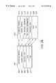
- FIG. 2Ais a diagram comparing one embodiment of an untagged frame and a VLAN tagged frame in accordance with the teachings of the present invention.
- FIG. 2Bis a diagram of one embodiment of an internal formatted frame and an internal system header in accordance with the teachings of the present invention.
- FIG. 3is a diagram illustrating one embodiment of internal elements of interconnected switches of a VLAN and in accordance with the teachings of the present invention.
- a method and an apparatus for transferring tagged and untagged frames between devices in a virtual local area networkis disclosed.
- numerous specific detailsare set forth in order to provide a thorough understanding of the present invention. It will be apparent, however, to one having ordinary skill in the art that the specific detail need not be employed to practice the present invention. In other instances, well-known materials or methods have not been described in detail in order to avoid obscuring the present invention.
- FIG. 1is a block diagram illustrating one embodiment of a network 100 in accordance with the teachings of the present invention.
- network 100includes a box 101 coupled to a box 103 through an interface 105 .
- boxes 101 and 103are network switches used to interconnect a plurality of network devices such as for example but not limited to workstations, servers, hubs or the like.
- interface 105is a high-speed connection such as for example a high-speed network backbone, packet bus, shared packet memory, trunk or the like.
- boxes 101 and 103each include a plurality of ports, each of which may be coupled to a corresponding device.
- devices 113 , 115 , 117 and 119are coupled to ports 1 , 2 , 3 and 4 , respectively, of box 101 .
- devices 121 , 123 , 125 and 127are coupled to ports 1 , 2 , 3 and 4 , respectively, of box 103 .
- each of the ports in boxes 101 and 103may be configured as both inbound and outbound ports enabling full-duplex communications. It is appreciated that in other embodiments, boxes 101 and 103 may have a greater or less number of ports in accordance with the teachings of the present invention.
- boxes 101 and 103implement Ethernet switching to provide high-speed data communications between devices. It is appreciated that in other embodiments, other communications protocols may be utilized in accordance with the teachings of the present invention.
- a virtual local area network (VLAN) architectureis included in network 100 .
- VLANvirtual local area network
- the implementations of VLANsgreatly reduce obstacles to departmental networking that result from physical boundaries between resources. For example, departmental resources spread among several buildings may be consolidated into a single VLAN making independent physical subnets unnecessary.
- devices 113 , 115 and 123are members of VLAN A 107 .
- Devices 119 , 121 and 127are members of VLAN B 109 .
- Devices 117 and 125are members of VLAN C 111 .
- boxes 101 and 103identify and route data frames transferred among the devices of each particular VLAN according to VLAN tags that are included within each data frame.
- the tagsare generated and interpreted by boxes 101 and 103 , such that the implementation of the VLAN architecture is transparent to the non-VLAN aware devices.
- This aspect of the present inventionis useful to non-VLAN aware devices that may not have the ability to generate and interpret the VLAN tags that are added to data frames. It is noted that non-VLAN aware devices may include workstations or the like that were developed before VLAN standards were adopted.
- boxes 101 and 103In the instances where boxes 101 and 103 are coupled to non-VLAN aware devices, boxes 101 and 103 send and receive untagged frames to and from the non-VLAN aware devices.
- boxes 101 and 103maintain the VLAN tags internally by assigning a default port VLAN identifier. By using boxes 101 and 103 to maintain the VLAN tags, the non-VLAN aware devices to function as if they were connected to ordinary LANs, even though a VLAN architecture is implemented.
- the devices coupled to boxes 101 and 103may also include VLAN-aware devices that are able to generate and interpret the VLAN tags that are added to data frames.
- VLAN aware devicesmay include workstations or the like that were developed after VLAN standards were adopted.
- boxes 101 and 103send and receive tagged frames to and from the VLAN aware devices.
- FIG. 2Aillustrates a standard Ethernet encapsulation in comparison with an IEEE 802.1Q encapsulation of a data frame.
- frame 201is an Ethernet encapsulation
- frame 213is an IEEE 802.1Q encapsulation.
- an untagged framemay correspond to an Ethernet encapsulation and that a tagged frame may correspond to an IEEE 802.1Q encapsulation.
- a tagged framemay correspond to an IEEE 802.1Q encapsulation.
- other encapsulationsmay be utilized in accordance with the teachings of the present invention.
- frame 201in one embodiment includes a destination address field 203 , a source address field 205 , a protocol type field 207 , a data field 209 and a cyclical redundancy check (CRC) field 211 .
- destination address field 203includes 6 octets
- source address field 205includes 6 octets
- protocol type field 207includes 2 octets
- data field 209includes 46 to 1496 octets
- CRC field 211includes 4 octets.
- frame 213includes a destination address field 215 , a source address field 217 , a tag protocol identifier field 219 , a tag control information field 221 , a protocol type field 223 , a data field 225 and a CRC field 227 .
- destination address field 215includes 6 octets
- source address field 217includes 6 octets
- tag protocol identifier field 219includes 2 octets
- tag control information field 221includes 2 octets
- protocol type field 223includes 2 octets
- data field 225includes 46 to 1496 octets
- CRC field 227includes 4 octets.
- a VLAN tagcorresponds to tag protocol identifier field 219 and tag control information field 221 , which are added to an Ethernet frame 201 .
- tagged frame 213is bigger than untagged frame 201 since tagged frame 213 contains the VLAN tag information as well as the standard Ethernet information included in frame 201 . It is appreciated that other encapsulations may be utilized for tagging data frames in accordance with the teachings of the present invention.
- Table 1summarizes the relationship between the various VLANs and devices illustrated in FIG. 1 .
- VLAN A 107includes devices 113 , 115 and 123
- VLAN B 109includes devices 119 , 121 and 127
- VLAN C 111includes devices 117 and 125 .
- devices 113 , 117 , 119 , 121 , 123 and 125are VLAN aware devices, so they send and receive frames that are tagged.
- Devices 115 and 127are non-VLAN aware devices in the described embodiment, so they send and receive untagged frames. Accordingly, in one embodiment, boxes 101 and 103 transfer tagged frames to and from VLAN aware devices and transfer untagged frames to and from non-VLAN aware devices.
- Operation of network 100 of FIG. 1may be summarized as follows.
- port 1 of box 101receives a tagged frame.
- port 1 of box 101may be considered an inbound port in this example.
- Box 101then sends the frame over interface 105 to box 103 .
- Box 103then forwards the tagged frame to device 123 at port 2 .
- port 2 of box 103may be considered an outbound port in this example.
- device 113 sends information to device 115an untagged frame is forwarded to device 115 instead of a tagged frame because device 115 is non-VLAN aware. Communications among the VLAN aware and non-VLAN aware devices of VLAN B 109 and VLAN C 111 are similar to those described with respect to VLAN A 107 .
- boxes 101 and 103 of the VLAN architecture described abovehave the ability to accommodate the all of following cases: (1) receiving a tagged frame and sending a tagged frame; (2) receiving an untagged frame and sending an untagged frame; (3) receiving an untagged frame and sending a tagged frame; and (4) receiving a tagged frame and sending an untagged frame.
- a source devicemay send a frame that may be received by more than one destination device and that the destination devices do not necessarily all have to be the same type. That is, the destination devices may be a combination of VLAN aware and non-VLAN aware devices.
- boxes 101 and 103convert the incoming frames received from the source devices to a common internal format such that frames containing the same data payload are transferred over interface 105 the same size, independent of whether the incoming frames are received tagged or untagged.
- tagged framesare converted to a size equal to the size of a corresonding untagged frame. Therefore, all of the frames transferred between boxes 101 and 103 that carry the same number of data bytes in fields 209 or 225 are the same size.
- system header 267includes system ingress info field 263 and VLAN identifier (VID) or port VLAN identifier (PVID) field 265 .
- VID or PVID field 265contains information that corresponds to the VID information that was received with incoming frame if the incoming frame arrived in a tagged format.
- VID or PVID field 265is assigned default PVID information that corresponds to the ingress port at which the untagged frame was received.
- all of the frames transferred between boxes 101 and 103are converted to be the same size with internal formatted frame 251 and internal system header 267 .
- tag protocol identifier field 219 and tag control information field 221are removed from the incoming tagged frame when converting to the internal format of frame 251 .
- the removed VLAN informationis preserved in system header 267 as VID information in the VID or PVID field 265 . As will be discussed in greater detail below, this will allow the incoming tagged frame to be reconstructed later as received.
- the frameif the frame arrives in the inbound port in an untagged format, then the frame is not reformatted. However, the untagged frame is assigned a default port VLAN identifier, which is included in the system header 267 as PVID information in the VID or PVID field 265 . Thus, tag information (VID or PVID) is associated with all frames internally in system header 267 . Therefore, all of the frames transferred among the ports are the same smaller size of the internal frame 251 with VLAN information in system header 267 , independent of whether the frame was received from a VLAN aware device or a non-VLAN aware device.
- the frameWhen the frame ultimately reaches the outbound port, the frame is converted from the internal format of frame 251 to a format depending on whether a VLAN aware device or a non-VLAN device is connected to the outbound port. If a VLAN aware device is connected to the outbound port, then appropriate tag information is added to the frame. If a non-VLAN aware device is connected to the outbound port, then the frame is forwarded to the device in an untagged format.
- both the Ethernet encapsulation, shown in frame 201 , and the IEEE 802.1Q encapsulation, shown in frame 213include corresponding CRC fields 209 and 227 , respectively.
- the CRC fields 209 and 227are error detection codes that enable the detection of errors in their respective frames. For example, if frame 201 becomes corrupted during transmission through the network, CRC field 211 will be inconsistent with the information contained in frame 201 and an error may be detected using known techniques. Similarly, if frame 213 becomes corrupted during transmission through the network, CRC field 227 will be inconsistent with the information contained in frame 213 and an error may be detected using known techniques.
- the error detection information contained in the CRC field of the frame as received at the inbound portwill not correspond to its associated frame if the frame is reformatted when forwarded out the outbound port.
- this situationarises when an untagged frame is received at the inbound port but is forwarded as a tagged frame at the outbound port.
- This situationalso arises when a tagged frame is received at the inbound port but is forwarded as an untagged frame at the outbound port.
- a new corresponding error detection codeis generated at the outbound port for each frame that is forwarded in a different format.
- each destination devicereceives valid CRC information in accordance with the teachings of the present invention. If a VLAN aware device is coupled to the outbound port, a new CRC field 227 is generated at the outbound port corresponding to frame 213 if the frame originated from a non-VLAN aware device. If a non-VLAN aware device is coupled to the outbound port, a new CRC field 211 is generated at the outbound port corresponding to frame 201 if the frame originated from a VLAN aware device.
- system header 267to enable frames to be reconstructed as originally received at the inbound ports, assuming the original frame is not already available in the outbound box.
- reconstructionis accomplished by including information in internal system headers 267 to allow the VLAN tag information that was removed from tagged inbound frames to be reconstructed at the outbound port.
- the system headers 267are forwarded to the outbound ports from the inbound ports along with the internal data frames 251 . When the internal data frames 251 reach the outbound ports, the original frames are reconstructed using the information included in the system headers 267 to recreate the frames as they were originally received at the inbound ports.
- the originally received frameAfter the originally received frame is obtained, it is verified against original CRC code received at the inbound port and transferred through the system to verify data integrity. In one embodiment, if discrepancy is detected between the originally received data frame and the original CRC code received at the inbound port, then an error has been detected.
- the step of verifying the originally received frameis executed in parallel with the step of generating a new error detection code for the forwarded frame to maintain performance.
- the verification stepis completed before the new error detection code is completely forwarded through the outbound port to the destination device.
- the new error detection code that is generated for the frame being forwarded to the destination deviceis intentionally corrupted.
- the corrupted error detection codewill therefore be inconsistent with the frame being transferred to the destination device. If the verification step is successful, however, the new error detection code is not corrupted and is therefore properly forwarded to the destination device through the outbound port.
- a corrupt frameis corrupted within the system, a correspondingly corrupt frame is transferred from the outbound port. If a valid frame is received at the inbound port and is not corrupted while being transferred within the system, a valid frame is transferred from the outbound port.
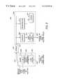
- FIG. 3is a block diagram of one embodiment of network 300 in accordance with the teachings of the present invention.
- a box 301is coupled to box 303 via an interface 305 .
- interface 305is a high-speed connection such as for example a high-speed network backbone, packet bus, shared packet memory, trunk or the like.
- box 301includes an inbound port 302 coupled to receive a frame from a sending device.
- Box 303includes an outbound port 304 coupled to forward a frame to a receiving device.
- boxes 301 and 303each include a plurality of both inbound and outbound ports in accordance with the teachings of the present invention.
- the elements contained in box 301are symmetric with the elements included in box 303 and vice versa.
- the elements in box 301are also included in box 303 and the elements included within box 303 are also included within box 301 .
- framesmay be transferred to or from boxes 301 and 303 through interface 305 .
- a frame received at inbound port 302is assumed to be addressed for the device coupled to outbound port 304 and is thus forwarded by box 301 to box 303 via interface 305 .
- an internal system header corresponding to the forwarded frameis also forwarded from box 301 to box 303 via interface 305 .
- box 301includes an error checker 323 coupled to a converter/header generator 307 coupled to a memory 308 .
- Error checker 323is coupled to receive a frame from inbound port 302 .
- the frame received through inbound port 302may be untagged or tagged as illustrated in frames 201 or 213 , respectively, of FIG. 2 . If an untagged frame is received, error checker 323 checks for errors in the received frame using CRC field 211 . If a tagged frame is received, error checker 323 checks for errors in the received frame using CRC field 227 . If no errors are detected, the frame is forwarded to converter/header generator 307 .
- converter/header generator 307is used to convert frames from a tagged format to an untagged format. For instance, in one embodiment, converter/header generator 307 converts received tagged frames to the untagged internally formatted frames, illustrated in frame 251 of FIG. 2 B. Converter/header generator 307 also generates the corresponding internal system header 267 . In one embodiment, the VLAN information stripped from the tagged frame is preserved as VID information in the internal system header 267 .
- converter/header generator 307if frames are received in an untagged format from inbound bound port 302 , converter/header generator 307 simply forwards the frame in the untagged format. For instance, if Ethernet encapsulated frames, which are illustrated in FIG. 2A as frame 201 are received, converter/header generator 307 generates the corresponding untagged internally formatted frames, illustrated as frame 251 in FIG. 2 B. However, converter/header generator 307 also generates the corresponding internal system header, which is illustrated in FIG. 2B as system header 267 . In one embodiment, the VLAN information stored in the system header 267 generated for an untagged frame includes the PVID information that corresponds to inbound port 302 .
- the original CRC information of the inbound framesis not changed and is forwarded as received from inbound port 302 . It is worthwhile to note that because the original CRC information is forwarded, the CRC information may or may not be consistent with the forwarded frame. This is because there are some instances when a tagged frame may be received at input port with valid CRC information, but the frame is converted to the untagged internal format of frame 251 without updating the CRC information. In addition, it is noted that when inbound frames are converted from the tagged to the untagged internal format, sufficient VID information is stored in the system header to enable the frames to be later reconstructed as received.
- converter/header generator 307After converter/header generator 307 generates the internal formatted frames 251 and generates the internal system headers 267 , the information is buffered in memory 308 before being forwarded to box 303 via interface 305 though input/output port 317 .
- all of the received incoming framesare converted to the common internal format illustrated frame 251 such that all frames containing the same data payload are transferred over interface 305 the same size. Therefore, in one embodiment, the burst transfers of information into and out of memory 308 involve same sized data frames. Since same sized data frames are transferred into and out of memory 308 over interface 305 , memory bandwidth efficiency is improved and the possibility of data under-run errors is reduced. As can be appreciated to those skilled in the art, if variable sized data frames were transferred through the system, the possibility of data under-run errors would be increased.
- the untagged internal frame plus the internal system header containing VLAN informationis forwarded from converter/header generator 307 to memory 308 , and from memory 308 to box 303 through interface 305 .
- the internal system header transferred from box 301 to box 303contains the VLAN information that enables reconstruction of the tagged frame as received at port 302 in box 303 . If an untagged frame is received from inbound port 302 , reconstruction will not be necessary in one embodiment since the original frame will be included in the internally formatted frame that is transferred from box 301 to box 303 .
- Box 303includes a converter 309 , a reconstructor 313 and a verifier 315 coupled to receive the forwarded frame and system header from interface 305 through an input/output port 319 .
- An error detection code generator 311is coupled between an output of converter/header generator 307 and outbound port 304 .
- An output of reconstructor 311is coupled to an input of verifier 315 .
- An output of verifier 315is coupled to an input error detection code generator 311 .
- a VLAN aware deviceis coupled to outbound port 304 , then a tagged frame is forwarded out of outbound port 304 .
- converter 309converts the untagged internal frame received over interface 305 to a tagged frame.
- Error detection code generator 311then receives the converted frame and a new error detection code is generated corresponding to the converted frame. The new error detection code is then inserted into the CRC field 227 of the tagged packet. The tagged packet is then forwarded to the receiving device through outbound port 304 .
- converter 309converts the untagged internal frame received over interface 305 to an untagged format suitable to be received by the receiving device coupled to outbound port 304 . In one embodiment, converter 309 simply passes the untagged internal frame received over interface 305 to error detection code generator 311 .
- error detection code generator 311receives the frame from converter 309 and a new error detection code is generated corresponding to the converted frame. The new error detection code is then inserted into the CRC field 211 of the untagged packet. There may be some instances when existing error detection code in CRC field 211 already corresponds to the frame output by converter 309 such that error detection code generator 311 does not need to regenerate a valid error detection code. In this instance, error detection code generator 311 simply passes the existing error detection code in CRC field 211 . The tagged frame is then forwarded to the receiving device through outbound port 304 .
- reconstructor 313receives the untagged internal frame and system header from interface 305 .
- Reconstructor 313reconstructs the frame as originally received at inbound port 302 based on the untagged frame and system header received from interface 305 .
- reconstructor 313simply passes the frame unchanged in one embodiment.
- Verifier 315then receives the frame output by reconstructor 313 and verifies the frame against the error detection code information included in the untagged internal frame received from interface 305 .
- the error detection code information included in the original CRC field 261 of the untagged internal frame received from interface 305is the original error detection code received at inbound port 302 .
- verifier 315detects an inconsistency between the original error detection code and the reconstructed frame, then a corrupt frame was received at inbound port 302 or the frame was corrupted while being transferred within the system. As a result, the new error detection code generated by error detection code generator 311 is corrupted such that the device coupled to outbound port 304 also receives a corrupt frame. If verifier 315 does not detect an inconsistency between the original error detection code and the reconstructed frame, then a valid new error detection code generated by error detection code generator 311 and is transmitted to outbound port 304 .
- a data communications networkhas been described.
- the present inventionhas been described in the context of a VLAN, it is appreciated that the present invention also has other networking applications that modify the encapsulations of frames transferred among network devices.
- the error detection codes included in the framesmay not be consistent with the corresponding frames.
- the presently described inventionmodifies frame formats transferred among network devices and maintains the error detection codes such that the data is properly transferred throughout the network.
Landscapes
- Engineering & Computer Science (AREA)
- Computer Networks & Wireless Communication (AREA)
- Signal Processing (AREA)
- Computer Security & Cryptography (AREA)
- Data Exchanges In Wide-Area Networks (AREA)
Abstract
Description
| TABLE 1 |
| Relationship of Devices and VLANs in Figure 1 |
| Send/Receive | |||
| Device | VLAN Member | Type | Frames |
| 113 | A | VLAN Aware | Tagged |
| 115 | A | Non-VLAN Aware | Untagged |
| 117 | C | VLAN Aware | Tagged |
| 119 | B | VLAN Aware | Tagged |
| 121 | B | VLAN Aware | Tagged |
| 123 | A | VLAN Aware | Tagged |
| 125 | C | VLAN Aware | Tagged |
| 127 | B | Non-VLAN Aware | Untagged |
Claims (34)
Priority Applications (1)
| Application Number | Priority Date | Filing Date | Title |
|---|---|---|---|
| US09/060,166US6252888B1 (en) | 1998-04-14 | 1998-04-14 | Method and apparatus providing network communications between devices using frames with multiple formats |
Applications Claiming Priority (1)
| Application Number | Priority Date | Filing Date | Title |
|---|---|---|---|
| US09/060,166US6252888B1 (en) | 1998-04-14 | 1998-04-14 | Method and apparatus providing network communications between devices using frames with multiple formats |
Publications (1)
| Publication Number | Publication Date |
|---|---|
| US6252888B1true US6252888B1 (en) | 2001-06-26 |
Family
ID=22027797
Family Applications (1)
| Application Number | Title | Priority Date | Filing Date |
|---|---|---|---|
| US09/060,166Expired - LifetimeUS6252888B1 (en) | 1998-04-14 | 1998-04-14 | Method and apparatus providing network communications between devices using frames with multiple formats |
Country Status (1)
| Country | Link |
|---|---|
| US (1) | US6252888B1 (en) |
Cited By (52)
| Publication number | Priority date | Publication date | Assignee | Title |
|---|---|---|---|---|
| US20010040890A1 (en)* | 2000-03-02 | 2001-11-15 | Nec Corporation | Network interconnection system |
| US20020091795A1 (en)* | 2001-01-05 | 2002-07-11 | Michael Yip | Method and system of aggregate multiple VLANs in a metropolitan area network |
| US6430621B1 (en)* | 1998-12-29 | 2002-08-06 | Nortel Networks Limited | System using different tag protocol identifiers to distinguish between multiple virtual local area networks |
| US6442161B1 (en)* | 1998-06-05 | 2002-08-27 | 3Com Corporation | Data packet transmission |
| US6574238B1 (en)* | 1998-08-26 | 2003-06-03 | Intel Corporation | Inter-switch link header modification |
| US6684363B1 (en) | 2000-10-25 | 2004-01-27 | Sun Microsystems, Inc. | Method for detecting errors on parallel links |
| US6694369B1 (en)* | 2000-03-30 | 2004-02-17 | 3Com Corporation | Tag echo discovery protocol to detect reachability of clients |
| US20040160895A1 (en)* | 2003-02-14 | 2004-08-19 | At&T Corp. | Failure notification method and system in an ethernet domain |
| US20040165595A1 (en)* | 2003-02-25 | 2004-08-26 | At&T Corp. | Discovery and integrity testing method in an ethernet domain |
| US6862280B1 (en)* | 2000-03-02 | 2005-03-01 | Alcatel | Priority remapping for data communication switch |
| US20050058132A1 (en)* | 2002-05-20 | 2005-03-17 | Fujitsu Limited | Network repeater apparatus, network repeater method and network repeater program |
| US20050083952A1 (en)* | 2003-10-15 | 2005-04-21 | Texas Instruments Incorporated | Flexible ethernet bridge |
| US20050138171A1 (en)* | 2003-12-19 | 2005-06-23 | Slaight Thomas M. | Logical network traffic filtering |
| US6914905B1 (en) | 2000-06-16 | 2005-07-05 | Extreme Networks, Inc. | Method and system for VLAN aggregation |
| US6928480B1 (en)* | 2000-09-19 | 2005-08-09 | Nortel Networks Limited | Networking device and method for providing a predictable membership scheme for policy-based VLANs |
| US20050174941A1 (en)* | 2004-02-09 | 2005-08-11 | Shanley Timothy M. | Methods and apparatus for controlling the flow of multiple signal sources over a single full duplex ethernet link |
| US6931581B1 (en)* | 2000-10-25 | 2005-08-16 | Sun Microsystems, Inc. | Method for superimposing a sequence number in an error detection code in a data network |
| US20050249247A1 (en)* | 2004-05-05 | 2005-11-10 | Transwitch Corporation | Methods and apparatus for multiplexing multiple signal sources over a single full duplex ETHERNET link |
| US20060184860A1 (en)* | 2005-02-16 | 2006-08-17 | Fujitsu Limited | Data repeating device and data communications system with adaptive error correction |
| EP1293353A3 (en)* | 2001-09-12 | 2006-12-13 | Xerox Corporation | Print line segmentation |
| US20080186980A1 (en)* | 2007-02-05 | 2008-08-07 | Koninklijke Kpn N.V. | VLAN numbering in access networks |
| US20090055709A1 (en)* | 2003-06-02 | 2009-02-26 | Qualcomm Incorporated | Generating and implementing a signal protocol and interface for higher data rates |
| US20090138588A1 (en)* | 2007-11-27 | 2009-05-28 | At&T Services, Inc. | Method of performing ethernet gateway switch trouble diagnostics |
| US20100295782A1 (en)* | 2009-05-21 | 2010-11-25 | Yehuda Binder | System and method for control based on face ore hand gesture detection |
| EP1542408A4 (en)* | 2002-08-22 | 2010-12-01 | Nec Corp | Frame transfer method and node in ethernet(r) |
| US20100309908A1 (en)* | 2009-06-08 | 2010-12-09 | Hewlett-Packard Development Company, L.P. | Method and system for communicating with a network device |
| US8190966B1 (en)* | 2002-04-24 | 2012-05-29 | Juniper Networks, Inc. | Systems and methods for implementing end-to-end checksum |
| US8539119B2 (en) | 2004-11-24 | 2013-09-17 | Qualcomm Incorporated | Methods and apparatus for exchanging messages having a digital data interface device message format |
| US8606946B2 (en) | 2003-11-12 | 2013-12-10 | Qualcomm Incorporated | Method, system and computer program for driving a data signal in data interface communication data link |
| US8611215B2 (en) | 2005-11-23 | 2013-12-17 | Qualcomm Incorporated | Systems and methods for digital data transmission rate control |
| US8625625B2 (en) | 2004-03-10 | 2014-01-07 | Qualcomm Incorporated | High data rate interface apparatus and method |
| US8630305B2 (en) | 2004-06-04 | 2014-01-14 | Qualcomm Incorporated | High data rate interface apparatus and method |
| US8635358B2 (en) | 2003-09-10 | 2014-01-21 | Qualcomm Incorporated | High data rate interface |
| US8645566B2 (en) | 2004-03-24 | 2014-02-04 | Qualcomm Incorporated | High data rate interface apparatus and method |
| US8650304B2 (en) | 2004-06-04 | 2014-02-11 | Qualcomm Incorporated | Determining a pre skew and post skew calibration data rate in a mobile display digital interface (MDDI) communication system |
| US8667363B2 (en) | 2004-11-24 | 2014-03-04 | Qualcomm Incorporated | Systems and methods for implementing cyclic redundancy checks |
| US8670457B2 (en) | 2003-12-08 | 2014-03-11 | Qualcomm Incorporated | High data rate interface with improved link synchronization |
| US8687658B2 (en) | 2003-11-25 | 2014-04-01 | Qualcomm Incorporated | High data rate interface with improved link synchronization |
| US8692839B2 (en) | 2005-11-23 | 2014-04-08 | Qualcomm Incorporated | Methods and systems for updating a buffer |
| US8694652B2 (en) | 2003-10-15 | 2014-04-08 | Qualcomm Incorporated | Method, system and computer program for adding a field to a client capability packet sent from a client to a host |
| US8692838B2 (en) | 2004-11-24 | 2014-04-08 | Qualcomm Incorporated | Methods and systems for updating a buffer |
| US8694663B2 (en) | 2001-09-06 | 2014-04-08 | Qualcomm Incorporated | System for transferring digital data at a high rate between a host and a client over a communication path for presentation to a user |
| US8705571B2 (en) | 2003-08-13 | 2014-04-22 | Qualcomm Incorporated | Signal interface for higher data rates |
| US8705521B2 (en) | 2004-03-17 | 2014-04-22 | Qualcomm Incorporated | High data rate interface apparatus and method |
| US8730069B2 (en) | 2005-11-23 | 2014-05-20 | Qualcomm Incorporated | Double data rate serial encoder |
| US8745251B2 (en) | 2000-12-15 | 2014-06-03 | Qualcomm Incorporated | Power reduction system for an apparatus for high data rate signal transfer using a communication protocol |
| US8756294B2 (en) | 2003-10-29 | 2014-06-17 | Qualcomm Incorporated | High data rate interface |
| US20140169182A1 (en)* | 2012-12-17 | 2014-06-19 | Litepoint Corporation | System and method for parallel testing of multiple data packet signal transceivers |
| US8873584B2 (en) | 2004-11-24 | 2014-10-28 | Qualcomm Incorporated | Digital data interface device |
| US9203717B2 (en) | 2013-12-19 | 2015-12-01 | Google Inc. | Detecting network devices |
| US9240898B1 (en)* | 2008-02-28 | 2016-01-19 | Marvell Israel (M.I.S.L.) Ltd. | Integrating VLAN-unaware devices into VLAN-enabled networks |
| GB2633136A (en)* | 2023-02-28 | 2025-03-05 | Advanced Risc Mach Ltd | Application of error detecting codes in a protocol-translating interconnect circuit |
Citations (6)
| Publication number | Priority date | Publication date | Assignee | Title |
|---|---|---|---|---|
| US5872781A (en) | 1995-07-12 | 1999-02-16 | Compaq Computer Corp. | Method and apparatus for displaying port information |
| US5935268A (en)* | 1997-06-03 | 1999-08-10 | Bay Networks, Inc. | Method and apparatus for generating an error detection code for a modified data packet derived from an original data packet |
| US5987034A (en)* | 1996-08-30 | 1999-11-16 | Cisco Technology, Inc. | ATM cells within frame relay technology |
| US6038227A (en)* | 1997-03-12 | 2000-03-14 | Bell Atlantic Network Services, Inc. | Preselection of service provider and functionality |
| US6049528A (en)* | 1997-06-30 | 2000-04-11 | Sun Microsystems, Inc. | Trunking ethernet-compatible networks |
| US6094439A (en)* | 1997-08-15 | 2000-07-25 | Advanced Micro Devices, Inc. | Arrangement for transmitting high speed packet data from a media access controller across multiple physical links |
- 1998
- 1998-04-14USUS09/060,166patent/US6252888B1/ennot_activeExpired - Lifetime
Patent Citations (6)
| Publication number | Priority date | Publication date | Assignee | Title |
|---|---|---|---|---|
| US5872781A (en) | 1995-07-12 | 1999-02-16 | Compaq Computer Corp. | Method and apparatus for displaying port information |
| US5987034A (en)* | 1996-08-30 | 1999-11-16 | Cisco Technology, Inc. | ATM cells within frame relay technology |
| US6038227A (en)* | 1997-03-12 | 2000-03-14 | Bell Atlantic Network Services, Inc. | Preselection of service provider and functionality |
| US5935268A (en)* | 1997-06-03 | 1999-08-10 | Bay Networks, Inc. | Method and apparatus for generating an error detection code for a modified data packet derived from an original data packet |
| US6049528A (en)* | 1997-06-30 | 2000-04-11 | Sun Microsystems, Inc. | Trunking ethernet-compatible networks |
| US6094439A (en)* | 1997-08-15 | 2000-07-25 | Advanced Micro Devices, Inc. | Arrangement for transmitting high speed packet data from a media access controller across multiple physical links |
Non-Patent Citations (11)
| Title |
|---|
| "3COM Transcend VLANs: Leveraging Virtual LAN Technology to Make Networking Easier", 3Com Strategic Directions, 3Com Corp., 1996. |
| "Ethernet Tutorial" at http://www.six.es/tutorial.htm, Manual Ethernet Page, Mar. 8, 1998. |
| "Fast IP: Enhanced Performance and Control in Switched Networks", 3Com Technical Papers, 3Com Corp., 1997. |
| "Release Notes for the BayStack Model 350T 10/100 Autosense Switch" Part No. 896-00162-A, Bay Networks, Mar. 1997. |
| "Switch Node Product Description" Part. No. 11347 Rev. A, Bay Networks,May 1997. |
| "The Virtual LAN Technology Report" at http://www.3com.com/nsc/200374.html, 3COM Corp, Jan. 28, 1998. |
| "Virtual LAN Communications" at http://cio.cisco.com/warp/public/614/13.html, Cisco Systems Inc., Jan. 28, 1998. |
| "Virtual Lan Communications", at http://cio.cisco.com/warp/public/614/13/html, Cisco Systems Inc., 1996. |
| "Virtual Local Area Nwtworks" at http://www.cis.ohio.state.edu/-jain/cis788-97/virtual_lans/index.htm, Cisco Systems Inc., modified Aug. 14, 1997. |
| "VLAN Interoperability" at http//cto.cisco.com/warp/public/537/6.html, Cisco Systems Inc, 1996. |
| Network 21 Cutover Workgroup: VLAN Information and Implementation (Draft ver 1.03, at http://net21policy.ucdavis.edu/newvlan.html;, Jan. 28, 1998. |
Cited By (75)
| Publication number | Priority date | Publication date | Assignee | Title |
|---|---|---|---|---|
| US6442161B1 (en)* | 1998-06-05 | 2002-08-27 | 3Com Corporation | Data packet transmission |
| US6574238B1 (en)* | 1998-08-26 | 2003-06-03 | Intel Corporation | Inter-switch link header modification |
| US6778554B2 (en) | 1998-08-26 | 2004-08-17 | Intel Corporation | Inter-switch link header modification |
| US6430621B1 (en)* | 1998-12-29 | 2002-08-06 | Nortel Networks Limited | System using different tag protocol identifiers to distinguish between multiple virtual local area networks |
| US20010040890A1 (en)* | 2000-03-02 | 2001-11-15 | Nec Corporation | Network interconnection system |
| US6975646B2 (en)* | 2000-03-02 | 2005-12-13 | Nec Corporation | Network interconnection system |
| US6862280B1 (en)* | 2000-03-02 | 2005-03-01 | Alcatel | Priority remapping for data communication switch |
| US6694369B1 (en)* | 2000-03-30 | 2004-02-17 | 3Com Corporation | Tag echo discovery protocol to detect reachability of clients |
| US7792058B1 (en) | 2000-06-16 | 2010-09-07 | Extreme Networks, Inc. | Method and system for VLAN aggregation |
| US6914905B1 (en) | 2000-06-16 | 2005-07-05 | Extreme Networks, Inc. | Method and system for VLAN aggregation |
| US6928480B1 (en)* | 2000-09-19 | 2005-08-09 | Nortel Networks Limited | Networking device and method for providing a predictable membership scheme for policy-based VLANs |
| US6684363B1 (en) | 2000-10-25 | 2004-01-27 | Sun Microsystems, Inc. | Method for detecting errors on parallel links |
| US6931581B1 (en)* | 2000-10-25 | 2005-08-16 | Sun Microsystems, Inc. | Method for superimposing a sequence number in an error detection code in a data network |
| US8745251B2 (en) | 2000-12-15 | 2014-06-03 | Qualcomm Incorporated | Power reduction system for an apparatus for high data rate signal transfer using a communication protocol |
| US20020091795A1 (en)* | 2001-01-05 | 2002-07-11 | Michael Yip | Method and system of aggregate multiple VLANs in a metropolitan area network |
| US6912592B2 (en) | 2001-01-05 | 2005-06-28 | Extreme Networks, Inc. | Method and system of aggregate multiple VLANs in a metropolitan area network |
| US8694663B2 (en) | 2001-09-06 | 2014-04-08 | Qualcomm Incorporated | System for transferring digital data at a high rate between a host and a client over a communication path for presentation to a user |
| US8812706B1 (en) | 2001-09-06 | 2014-08-19 | Qualcomm Incorporated | Method and apparatus for compensating for mismatched delays in signals of a mobile display interface (MDDI) system |
| EP1293353A3 (en)* | 2001-09-12 | 2006-12-13 | Xerox Corporation | Print line segmentation |
| US8190966B1 (en)* | 2002-04-24 | 2012-05-29 | Juniper Networks, Inc. | Systems and methods for implementing end-to-end checksum |
| US7450584B2 (en)* | 2002-05-20 | 2008-11-11 | Fujitsu Limited | Network repeater apparatus, network repeater method and network repeater program |
| US20050058132A1 (en)* | 2002-05-20 | 2005-03-17 | Fujitsu Limited | Network repeater apparatus, network repeater method and network repeater program |
| EP1542408A4 (en)* | 2002-08-22 | 2010-12-01 | Nec Corp | Frame transfer method and node in ethernet(r) |
| US20040160895A1 (en)* | 2003-02-14 | 2004-08-19 | At&T Corp. | Failure notification method and system in an ethernet domain |
| US20040165595A1 (en)* | 2003-02-25 | 2004-08-26 | At&T Corp. | Discovery and integrity testing method in an ethernet domain |
| US8700744B2 (en) | 2003-06-02 | 2014-04-15 | Qualcomm Incorporated | Generating and implementing a signal protocol and interface for higher data rates |
| US20090055709A1 (en)* | 2003-06-02 | 2009-02-26 | Qualcomm Incorporated | Generating and implementing a signal protocol and interface for higher data rates |
| US8681817B2 (en)* | 2003-06-02 | 2014-03-25 | Qualcomm Incorporated | Generating and implementing a signal protocol and interface for higher data rates |
| US8705579B2 (en) | 2003-06-02 | 2014-04-22 | Qualcomm Incorporated | Generating and implementing a signal protocol and interface for higher data rates |
| US8705571B2 (en) | 2003-08-13 | 2014-04-22 | Qualcomm Incorporated | Signal interface for higher data rates |
| US8719334B2 (en) | 2003-09-10 | 2014-05-06 | Qualcomm Incorporated | High data rate interface |
| US8635358B2 (en) | 2003-09-10 | 2014-01-21 | Qualcomm Incorporated | High data rate interface |
| US8694652B2 (en) | 2003-10-15 | 2014-04-08 | Qualcomm Incorporated | Method, system and computer program for adding a field to a client capability packet sent from a client to a host |
| US20050083952A1 (en)* | 2003-10-15 | 2005-04-21 | Texas Instruments Incorporated | Flexible ethernet bridge |
| US7860028B2 (en)* | 2003-10-15 | 2010-12-28 | Texas Instruments Incorporated | Flexible ethernet bridge |
| US20080239952A1 (en)* | 2003-10-15 | 2008-10-02 | Texas Instruments Incorporated | Flexible ethernet bridge |
| US7512078B2 (en)* | 2003-10-15 | 2009-03-31 | Texas Instruments Incorporated | Flexible ethernet bridge |
| US8756294B2 (en) | 2003-10-29 | 2014-06-17 | Qualcomm Incorporated | High data rate interface |
| US8606946B2 (en) | 2003-11-12 | 2013-12-10 | Qualcomm Incorporated | Method, system and computer program for driving a data signal in data interface communication data link |
| US8687658B2 (en) | 2003-11-25 | 2014-04-01 | Qualcomm Incorporated | High data rate interface with improved link synchronization |
| US8670457B2 (en) | 2003-12-08 | 2014-03-11 | Qualcomm Incorporated | High data rate interface with improved link synchronization |
| US20050138171A1 (en)* | 2003-12-19 | 2005-06-23 | Slaight Thomas M. | Logical network traffic filtering |
| US7649843B2 (en)* | 2004-02-09 | 2010-01-19 | Transwitch Corporation | Methods and apparatus for controlling the flow of multiple signal sources over a single full duplex ethernet link |
| US20050174941A1 (en)* | 2004-02-09 | 2005-08-11 | Shanley Timothy M. | Methods and apparatus for controlling the flow of multiple signal sources over a single full duplex ethernet link |
| US8730913B2 (en) | 2004-03-10 | 2014-05-20 | Qualcomm Incorporated | High data rate interface apparatus and method |
| US8669988B2 (en) | 2004-03-10 | 2014-03-11 | Qualcomm Incorporated | High data rate interface apparatus and method |
| US8625625B2 (en) | 2004-03-10 | 2014-01-07 | Qualcomm Incorporated | High data rate interface apparatus and method |
| US8705521B2 (en) | 2004-03-17 | 2014-04-22 | Qualcomm Incorporated | High data rate interface apparatus and method |
| US8645566B2 (en) | 2004-03-24 | 2014-02-04 | Qualcomm Incorporated | High data rate interface apparatus and method |
| US20050249247A1 (en)* | 2004-05-05 | 2005-11-10 | Transwitch Corporation | Methods and apparatus for multiplexing multiple signal sources over a single full duplex ETHERNET link |
| US8650304B2 (en) | 2004-06-04 | 2014-02-11 | Qualcomm Incorporated | Determining a pre skew and post skew calibration data rate in a mobile display digital interface (MDDI) communication system |
| US8630305B2 (en) | 2004-06-04 | 2014-01-14 | Qualcomm Incorporated | High data rate interface apparatus and method |
| US8692838B2 (en) | 2004-11-24 | 2014-04-08 | Qualcomm Incorporated | Methods and systems for updating a buffer |
| US8873584B2 (en) | 2004-11-24 | 2014-10-28 | Qualcomm Incorporated | Digital data interface device |
| US8539119B2 (en) | 2004-11-24 | 2013-09-17 | Qualcomm Incorporated | Methods and apparatus for exchanging messages having a digital data interface device message format |
| US8667363B2 (en) | 2004-11-24 | 2014-03-04 | Qualcomm Incorporated | Systems and methods for implementing cyclic redundancy checks |
| US8699330B2 (en) | 2004-11-24 | 2014-04-15 | Qualcomm Incorporated | Systems and methods for digital data transmission rate control |
| US7555700B2 (en)* | 2005-02-16 | 2009-06-30 | Fujitsu Limited | Data repeating device and data communications system with adaptive error correction |
| US20060184860A1 (en)* | 2005-02-16 | 2006-08-17 | Fujitsu Limited | Data repeating device and data communications system with adaptive error correction |
| US8692839B2 (en) | 2005-11-23 | 2014-04-08 | Qualcomm Incorporated | Methods and systems for updating a buffer |
| US8611215B2 (en) | 2005-11-23 | 2013-12-17 | Qualcomm Incorporated | Systems and methods for digital data transmission rate control |
| US8730069B2 (en) | 2005-11-23 | 2014-05-20 | Qualcomm Incorporated | Double data rate serial encoder |
| US20080186980A1 (en)* | 2007-02-05 | 2008-08-07 | Koninklijke Kpn N.V. | VLAN numbering in access networks |
| US8340107B2 (en)* | 2007-02-05 | 2012-12-25 | Koninklijke Kpn N.V. | VLAN numbering in access networks |
| US8964768B2 (en) | 2007-02-05 | 2015-02-24 | Koninklijke Kpn N.V. | VLAN numbering in access networks |
| US20090138588A1 (en)* | 2007-11-27 | 2009-05-28 | At&T Services, Inc. | Method of performing ethernet gateway switch trouble diagnostics |
| US8107381B2 (en) | 2007-11-27 | 2012-01-31 | At&T Intellectual Property I, Lp | Method of performing ethernet gateway switch trouble diagnostics |
| US9240898B1 (en)* | 2008-02-28 | 2016-01-19 | Marvell Israel (M.I.S.L.) Ltd. | Integrating VLAN-unaware devices into VLAN-enabled networks |
| US20100295782A1 (en)* | 2009-05-21 | 2010-11-25 | Yehuda Binder | System and method for control based on face ore hand gesture detection |
| US20100309908A1 (en)* | 2009-06-08 | 2010-12-09 | Hewlett-Packard Development Company, L.P. | Method and system for communicating with a network device |
| US8842549B2 (en)* | 2012-12-17 | 2014-09-23 | Litepoint Corporation | System and method for parallel testing of multiple data packet signal transceivers |
| US20140169182A1 (en)* | 2012-12-17 | 2014-06-19 | Litepoint Corporation | System and method for parallel testing of multiple data packet signal transceivers |
| US9203717B2 (en) | 2013-12-19 | 2015-12-01 | Google Inc. | Detecting network devices |
| GB2633136A (en)* | 2023-02-28 | 2025-03-05 | Advanced Risc Mach Ltd | Application of error detecting codes in a protocol-translating interconnect circuit |
| GB2633136B (en)* | 2023-02-28 | 2025-09-24 | Advanced Risc Mach Ltd | Application of error detecting codes in a protocol-translating interconnect circuit |
Similar Documents
| Publication | Publication Date | Title |
|---|---|---|
| US6252888B1 (en) | Method and apparatus providing network communications between devices using frames with multiple formats | |
| US7924882B2 (en) | Packet forwarding apparatus suitable for forwarding extended frame | |
| US6278708B1 (en) | Frame relay access device with user-configurable virtual circuit bundling | |
| EP2323342B1 (en) | Data transmission method and network node and data transmission system | |
| US6292495B1 (en) | Segmented permanent virtual circuits | |
| JP4057615B2 (en) | User MAC frame transfer method, edge transfer device, and program | |
| US5742604A (en) | Interswitch link mechanism for connecting high-performance network switches | |
| US8908704B2 (en) | Switch with dual-function management port | |
| US9077560B2 (en) | Adaptation scheme for communications traffic | |
| US7643424B2 (en) | Ethernet architecture with data packet encapsulation | |
| US6639917B1 (en) | Converged service for interconnected local area networks | |
| US9414136B2 (en) | Methods and apparatus to route fibre channel frames using reduced forwarding state on an FCoE-to-FC gateway | |
| US20030051045A1 (en) | Methods and apparatus for reducing frame overhead on local area networks | |
| US20040213232A1 (en) | Data mirroring in a service | |
| US20080310414A1 (en) | Retransmission of broadcast and multicast traffic over a shared medium | |
| EP1408655A2 (en) | Method and device for double tagging of data packets | |
| CN1441573A (en) | Virtual LAN connector | |
| EP1968249A1 (en) | A method for bearing the frame relay in ethernet | |
| US6414956B1 (en) | VLAN tag transport within a switch | |
| US20220407742A1 (en) | Time-sensitive transmission of ethernet traffic between endpoint network nodes | |
| JP2022516355A (en) | Data transmission method and equipment | |
| EP2071808B1 (en) | Methods and a system and devices for ipv6 datagram transmission in the ethernet | |
| CN109672572B (en) | Data transmission method and device | |
| US7839853B2 (en) | Transmitting apparatus and frame transfer method | |
| KR101086871B1 (en) | METHOD FOR TRANSMITTING IEEE 133.4 DATA ON A WIRELESS LINK AND EQUIPMENT IMPLEMENTING THE METHOD |
Legal Events
| Date | Code | Title | Description |
|---|---|---|---|
| AS | Assignment | Owner name:BAY NETWORKS GROUP, INC., CALIFORNIA Free format text:ASSIGNMENT OF ASSIGNORS INTEREST;ASSIGNORS:FITE, DAVID B. JR.;IIYADIS, NICHOLAS;SALETT, RONALD M.;REEL/FRAME:009104/0597 Effective date:19980413 | |
| AS | Assignment | Owner name:NORTEL NETWORKS GROUP INC., CALIFORNIA Free format text:CHANGE OF NAME;ASSIGNOR:BAY NETWORKS GROUP, INC.;REEL/FRAME:010470/0277 Effective date:19990420 | |
| AS | Assignment | Owner name:NORTEL NETWORKS CORPORATION, CANADA Free format text:ASSIGNMENT OF ASSIGNORS INTEREST;ASSIGNOR:NORTEL NETWORKS GROUP, INC;REEL/FRAME:010547/0430 Effective date:19991229 | |
| STCF | Information on status: patent grant | Free format text:PATENTED CASE | |
| FEPP | Fee payment procedure | Free format text:PAYOR NUMBER ASSIGNED (ORIGINAL EVENT CODE: ASPN); ENTITY STATUS OF PATENT OWNER: LARGE ENTITY | |
| AS | Assignment | Owner name:NORTEL NETWORKS LIMITED, CANADA Free format text:CHANGE OF NAME;ASSIGNOR:NORTEL NETWORKS CORPORATION;REEL/FRAME:013746/0330 Effective date:20010523 | |
| FPAY | Fee payment | Year of fee payment:4 | |
| FPAY | Fee payment | Year of fee payment:8 | |
| FEPP | Fee payment procedure | Free format text:PAYER NUMBER DE-ASSIGNED (ORIGINAL EVENT CODE: RMPN); ENTITY STATUS OF PATENT OWNER: LARGE ENTITY Free format text:PAYOR NUMBER ASSIGNED (ORIGINAL EVENT CODE: ASPN); ENTITY STATUS OF PATENT OWNER: LARGE ENTITY | |
| AS | Assignment | Owner name:AVAYA HOLDINGS LIMITED,NEW JERSEY Free format text:ASSIGNMENT OF ASSIGNORS INTEREST;ASSIGNOR:NORTEL NETWORKS LIMITED;REEL/FRAME:023998/0799 Effective date:20091218 Owner name:AVAYA HOLDINGS LIMITED, NEW JERSEY Free format text:ASSIGNMENT OF ASSIGNORS INTEREST;ASSIGNOR:NORTEL NETWORKS LIMITED;REEL/FRAME:023998/0799 Effective date:20091218 | |
| FPAY | Fee payment | Year of fee payment:12 | |
| AS | Assignment | Owner name:AVAYA MANAGEMENT L.P., DELAWARE Free format text:ASSIGNMENT OF ASSIGNORS INTEREST;ASSIGNOR:AVAYA HOLDINGS LIMITED;REEL/FRAME:048577/0492 Effective date:20190211 | |
| AS | Assignment | Owner name:GOLDMAN SACHS BANK USA, NEW YORK Free format text:SECURITY INTEREST;ASSIGNOR:AVAYA MANAGEMENT L.P.;REEL/FRAME:048612/0598 Effective date:20190315 Owner name:CITIBANK, N.A., NEW YORK Free format text:SECURITY INTEREST;ASSIGNOR:AVAYA MANAGEMENT L.P.;REEL/FRAME:048612/0582 Effective date:20190315 | |
| AS | Assignment | Owner name:AVAYA MANAGEMENT L.P., NEW JERSEY Free format text:RELEASE OF SECURITY INTEREST IN PATENTS AT REEL 48612/FRAME 0582;ASSIGNOR:CITIBANK, N.A., AS COLLATERAL AGENT;REEL/FRAME:063456/0428 Effective date:20230403 Owner name:AVAYA INC., NEW JERSEY Free format text:RELEASE OF SECURITY INTEREST IN PATENTS AT REEL 48612/FRAME 0582;ASSIGNOR:CITIBANK, N.A., AS COLLATERAL AGENT;REEL/FRAME:063456/0428 Effective date:20230403 Owner name:AVAYA HOLDINGS CORP., NEW JERSEY Free format text:RELEASE OF SECURITY INTEREST IN PATENTS AT REEL 48612/FRAME 0582;ASSIGNOR:CITIBANK, N.A., AS COLLATERAL AGENT;REEL/FRAME:063456/0428 Effective date:20230403 | |
| AS | Assignment | Owner name:AVAYA MANAGEMENT L.P., NEW JERSEY Free format text:RELEASE OF SECURITY INTEREST IN PATENTS (REEL/FRAME 48612/0598);ASSIGNOR:GOLDMAN SACHS BANK USA., AS COLLATERAL AGENT;REEL/FRAME:063691/0294 Effective date:20230501 Owner name:CAAS TECHNOLOGIES, LLC, NEW JERSEY Free format text:RELEASE OF SECURITY INTEREST IN PATENTS (REEL/FRAME 48612/0598);ASSIGNOR:GOLDMAN SACHS BANK USA., AS COLLATERAL AGENT;REEL/FRAME:063691/0294 Effective date:20230501 Owner name:HYPERQUALITY II, LLC, NEW JERSEY Free format text:RELEASE OF SECURITY INTEREST IN PATENTS (REEL/FRAME 48612/0598);ASSIGNOR:GOLDMAN SACHS BANK USA., AS COLLATERAL AGENT;REEL/FRAME:063691/0294 Effective date:20230501 Owner name:HYPERQUALITY, INC., NEW JERSEY Free format text:RELEASE OF SECURITY INTEREST IN PATENTS (REEL/FRAME 48612/0598);ASSIGNOR:GOLDMAN SACHS BANK USA., AS COLLATERAL AGENT;REEL/FRAME:063691/0294 Effective date:20230501 Owner name:ZANG, INC. (FORMER NAME OF AVAYA CLOUD INC.), NEW JERSEY Free format text:RELEASE OF SECURITY INTEREST IN PATENTS (REEL/FRAME 48612/0598);ASSIGNOR:GOLDMAN SACHS BANK USA., AS COLLATERAL AGENT;REEL/FRAME:063691/0294 Effective date:20230501 Owner name:VPNET TECHNOLOGIES, INC., NEW JERSEY Free format text:RELEASE OF SECURITY INTEREST IN PATENTS (REEL/FRAME 48612/0598);ASSIGNOR:GOLDMAN SACHS BANK USA., AS COLLATERAL AGENT;REEL/FRAME:063691/0294 Effective date:20230501 Owner name:OCTEL COMMUNICATIONS LLC, NEW JERSEY Free format text:RELEASE OF SECURITY INTEREST IN PATENTS (REEL/FRAME 48612/0598);ASSIGNOR:GOLDMAN SACHS BANK USA., AS COLLATERAL AGENT;REEL/FRAME:063691/0294 Effective date:20230501 Owner name:AVAYA INTEGRATED CABINET SOLUTIONS LLC, NEW JERSEY Free format text:RELEASE OF SECURITY INTEREST IN PATENTS (REEL/FRAME 48612/0598);ASSIGNOR:GOLDMAN SACHS BANK USA., AS COLLATERAL AGENT;REEL/FRAME:063691/0294 Effective date:20230501 Owner name:INTELLISIST, INC., NEW JERSEY Free format text:RELEASE OF SECURITY INTEREST IN PATENTS (REEL/FRAME 48612/0598);ASSIGNOR:GOLDMAN SACHS BANK USA., AS COLLATERAL AGENT;REEL/FRAME:063691/0294 Effective date:20230501 Owner name:AVAYA INC., NEW JERSEY Free format text:RELEASE OF SECURITY INTEREST IN PATENTS (REEL/FRAME 48612/0598);ASSIGNOR:GOLDMAN SACHS BANK USA., AS COLLATERAL AGENT;REEL/FRAME:063691/0294 Effective date:20230501 |