US6251113B1 - Ophthalmic microsurgical system employing surgical module employing flash EEPROM and reprogrammable modules - Google Patents
Ophthalmic microsurgical system employing surgical module employing flash EEPROM and reprogrammable modulesDownload PDFInfo
- Publication number
- US6251113B1 US6251113B1US08/919,611US91961197AUS6251113B1US 6251113 B1US6251113 B1US 6251113B1US 91961197 AUS91961197 AUS 91961197AUS 6251113 B1US6251113 B1US 6251113B1
- Authority
- US
- United States
- Prior art keywords
- module
- operating parameters
- user
- communications bus
- data communications
- Prior art date
- Legal status (The legal status is an assumption and is not a legal conclusion. Google has not performed a legal analysis and makes no representation as to the accuracy of the status listed.)
- Expired - Lifetime
Links
Images


Classifications
- H—ELECTRICITY
- H02—GENERATION; CONVERSION OR DISTRIBUTION OF ELECTRIC POWER
- H02H—EMERGENCY PROTECTIVE CIRCUIT ARRANGEMENTS
- H02H3/00—Emergency protective circuit arrangements for automatic disconnection directly responsive to an undesired change from normal electric working condition with or without subsequent reconnection ; integrated protection
- H02H3/12—Emergency protective circuit arrangements for automatic disconnection directly responsive to an undesired change from normal electric working condition with or without subsequent reconnection ; integrated protection responsive to underload or no-load
- A—HUMAN NECESSITIES
- A61—MEDICAL OR VETERINARY SCIENCE; HYGIENE
- A61B—DIAGNOSIS; SURGERY; IDENTIFICATION
- A61B17/00—Surgical instruments, devices or methods
- A—HUMAN NECESSITIES
- A61—MEDICAL OR VETERINARY SCIENCE; HYGIENE
- A61B—DIAGNOSIS; SURGERY; IDENTIFICATION
- A61B50/00—Containers, covers, furniture or holders specially adapted for surgical or diagnostic appliances or instruments, e.g. sterile covers
- A61B50/10—Furniture specially adapted for surgical or diagnostic appliances or instruments
- A61B50/13—Trolleys, e.g. carts
- A—HUMAN NECESSITIES
- A61—MEDICAL OR VETERINARY SCIENCE; HYGIENE
- A61B—DIAGNOSIS; SURGERY; IDENTIFICATION
- A61B50/00—Containers, covers, furniture or holders specially adapted for surgical or diagnostic appliances or instruments, e.g. sterile covers
- A61B50/10—Furniture specially adapted for surgical or diagnostic appliances or instruments
- A61B50/15—Mayo stands; Tables
- A—HUMAN NECESSITIES
- A61—MEDICAL OR VETERINARY SCIENCE; HYGIENE
- A61B—DIAGNOSIS; SURGERY; IDENTIFICATION
- A61B90/00—Instruments, implements or accessories specially adapted for surgery or diagnosis and not covered by any of the groups A61B1/00 - A61B50/00, e.g. for luxation treatment or for protecting wound edges
- A61B90/36—Image-producing devices or illumination devices not otherwise provided for
- A—HUMAN NECESSITIES
- A61—MEDICAL OR VETERINARY SCIENCE; HYGIENE
- A61F—FILTERS IMPLANTABLE INTO BLOOD VESSELS; PROSTHESES; DEVICES PROVIDING PATENCY TO, OR PREVENTING COLLAPSING OF, TUBULAR STRUCTURES OF THE BODY, e.g. STENTS; ORTHOPAEDIC, NURSING OR CONTRACEPTIVE DEVICES; FOMENTATION; TREATMENT OR PROTECTION OF EYES OR EARS; BANDAGES, DRESSINGS OR ABSORBENT PADS; FIRST-AID KITS
- A61F9/00—Methods or devices for treatment of the eyes; Devices for putting in contact-lenses; Devices to correct squinting; Apparatus to guide the blind; Protective devices for the eyes, carried on the body or in the hand
- A61F9/007—Methods or devices for eye surgery
- A61F9/00736—Instruments for removal of intra-ocular material or intra-ocular injection, e.g. cataract instruments
- A61F9/00745—Instruments for removal of intra-ocular material or intra-ocular injection, e.g. cataract instruments using mechanical vibrations, e.g. ultrasonic
- A—HUMAN NECESSITIES
- A61—MEDICAL OR VETERINARY SCIENCE; HYGIENE
- A61F—FILTERS IMPLANTABLE INTO BLOOD VESSELS; PROSTHESES; DEVICES PROVIDING PATENCY TO, OR PREVENTING COLLAPSING OF, TUBULAR STRUCTURES OF THE BODY, e.g. STENTS; ORTHOPAEDIC, NURSING OR CONTRACEPTIVE DEVICES; FOMENTATION; TREATMENT OR PROTECTION OF EYES OR EARS; BANDAGES, DRESSINGS OR ABSORBENT PADS; FIRST-AID KITS
- A61F9/00—Methods or devices for treatment of the eyes; Devices for putting in contact-lenses; Devices to correct squinting; Apparatus to guide the blind; Protective devices for the eyes, carried on the body or in the hand
- A61F9/007—Methods or devices for eye surgery
- A61F9/00736—Instruments for removal of intra-ocular material or intra-ocular injection, e.g. cataract instruments
- A61F9/00763—Instruments for removal of intra-ocular material or intra-ocular injection, e.g. cataract instruments with rotating or reciprocating cutting elements, e.g. concentric cutting needles
- G—PHYSICS
- G08—SIGNALLING
- G08C—TRANSMISSION SYSTEMS FOR MEASURED VALUES, CONTROL OR SIMILAR SIGNALS
- G08C19/00—Electric signal transmission systems
- G08C19/16—Electric signal transmission systems in which transmission is by pulses
- G08C19/28—Electric signal transmission systems in which transmission is by pulses using pulse code
- A—HUMAN NECESSITIES
- A61—MEDICAL OR VETERINARY SCIENCE; HYGIENE
- A61B—DIAGNOSIS; SURGERY; IDENTIFICATION
- A61B17/00—Surgical instruments, devices or methods
- A61B17/32—Surgical cutting instruments
- A61B17/3201—Scissors
- A—HUMAN NECESSITIES
- A61—MEDICAL OR VETERINARY SCIENCE; HYGIENE
- A61B—DIAGNOSIS; SURGERY; IDENTIFICATION
- A61B18/00—Surgical instruments, devices or methods for transferring non-mechanical forms of energy to or from the body
- A—HUMAN NECESSITIES
- A61—MEDICAL OR VETERINARY SCIENCE; HYGIENE
- A61B—DIAGNOSIS; SURGERY; IDENTIFICATION
- A61B18/00—Surgical instruments, devices or methods for transferring non-mechanical forms of energy to or from the body
- A61B18/04—Surgical instruments, devices or methods for transferring non-mechanical forms of energy to or from the body by heating
- A61B18/12—Surgical instruments, devices or methods for transferring non-mechanical forms of energy to or from the body by heating by passing a current through the tissue to be heated, e.g. high-frequency current
- A61B18/14—Probes or electrodes therefor
- A—HUMAN NECESSITIES
- A61—MEDICAL OR VETERINARY SCIENCE; HYGIENE
- A61B—DIAGNOSIS; SURGERY; IDENTIFICATION
- A61B17/00—Surgical instruments, devices or methods
- A61B2017/00017—Electrical control of surgical instruments
- A—HUMAN NECESSITIES
- A61—MEDICAL OR VETERINARY SCIENCE; HYGIENE
- A61B—DIAGNOSIS; SURGERY; IDENTIFICATION
- A61B17/00—Surgical instruments, devices or methods
- A61B2017/00017—Electrical control of surgical instruments
- A61B2017/00022—Sensing or detecting at the treatment site
- A61B2017/00026—Conductivity or impedance, e.g. of tissue
- A61B2017/0003—Conductivity or impedance, e.g. of tissue of parts of the instruments
- A—HUMAN NECESSITIES
- A61—MEDICAL OR VETERINARY SCIENCE; HYGIENE
- A61B—DIAGNOSIS; SURGERY; IDENTIFICATION
- A61B17/00—Surgical instruments, devices or methods
- A61B2017/00017—Electrical control of surgical instruments
- A61B2017/00022—Sensing or detecting at the treatment site
- A61B2017/00057—Light
- A—HUMAN NECESSITIES
- A61—MEDICAL OR VETERINARY SCIENCE; HYGIENE
- A61B—DIAGNOSIS; SURGERY; IDENTIFICATION
- A61B17/00—Surgical instruments, devices or methods
- A61B2017/00017—Electrical control of surgical instruments
- A61B2017/00137—Details of operation mode
- A61B2017/00154—Details of operation mode pulsed
- A61B2017/00181—Means for setting or varying the pulse energy
- A61B2017/00185—Means for setting or varying the pulse height
- A—HUMAN NECESSITIES
- A61—MEDICAL OR VETERINARY SCIENCE; HYGIENE
- A61B—DIAGNOSIS; SURGERY; IDENTIFICATION
- A61B17/00—Surgical instruments, devices or methods
- A61B2017/00017—Electrical control of surgical instruments
- A61B2017/00137—Details of operation mode
- A61B2017/00154—Details of operation mode pulsed
- A61B2017/00181—Means for setting or varying the pulse energy
- A61B2017/0019—Means for setting or varying the pulse width
- A—HUMAN NECESSITIES
- A61—MEDICAL OR VETERINARY SCIENCE; HYGIENE
- A61B—DIAGNOSIS; SURGERY; IDENTIFICATION
- A61B17/00—Surgical instruments, devices or methods
- A61B2017/00017—Electrical control of surgical instruments
- A61B2017/00199—Electrical control of surgical instruments with a console, e.g. a control panel with a display
- A—HUMAN NECESSITIES
- A61—MEDICAL OR VETERINARY SCIENCE; HYGIENE
- A61B—DIAGNOSIS; SURGERY; IDENTIFICATION
- A61B17/00—Surgical instruments, devices or methods
- A61B2017/00017—Electrical control of surgical instruments
- A61B2017/00225—Systems for controlling multiple different instruments, e.g. microsurgical systems
- A—HUMAN NECESSITIES
- A61—MEDICAL OR VETERINARY SCIENCE; HYGIENE
- A61B—DIAGNOSIS; SURGERY; IDENTIFICATION
- A61B17/00—Surgical instruments, devices or methods
- A61B2017/00477—Coupling
- A61B2017/00482—Coupling with a code
- A—HUMAN NECESSITIES
- A61—MEDICAL OR VETERINARY SCIENCE; HYGIENE
- A61B—DIAGNOSIS; SURGERY; IDENTIFICATION
- A61B17/00—Surgical instruments, devices or methods
- A61B2017/00535—Surgical instruments, devices or methods pneumatically or hydraulically operated
- A61B2017/00544—Surgical instruments, devices or methods pneumatically or hydraulically operated pneumatically
- A—HUMAN NECESSITIES
- A61—MEDICAL OR VETERINARY SCIENCE; HYGIENE
- A61B—DIAGNOSIS; SURGERY; IDENTIFICATION
- A61B17/00—Surgical instruments, devices or methods
- A61B2017/00973—Surgical instruments, devices or methods pedal-operated
- A—HUMAN NECESSITIES
- A61—MEDICAL OR VETERINARY SCIENCE; HYGIENE
- A61B—DIAGNOSIS; SURGERY; IDENTIFICATION
- A61B17/00—Surgical instruments, devices or methods
- A61B2017/00973—Surgical instruments, devices or methods pedal-operated
- A61B2017/00977—Surgical instruments, devices or methods pedal-operated the depression depth determining the power rate
- A—HUMAN NECESSITIES
- A61—MEDICAL OR VETERINARY SCIENCE; HYGIENE
- A61B—DIAGNOSIS; SURGERY; IDENTIFICATION
- A61B50/00—Containers, covers, furniture or holders specially adapted for surgical or diagnostic appliances or instruments, e.g. sterile covers
- A61B50/10—Furniture specially adapted for surgical or diagnostic appliances or instruments
- A61B50/15—Mayo stands; Tables
- A61B2050/155—Mayo stands
- A—HUMAN NECESSITIES
- A61—MEDICAL OR VETERINARY SCIENCE; HYGIENE
- A61B—DIAGNOSIS; SURGERY; IDENTIFICATION
- A61B50/00—Containers, covers, furniture or holders specially adapted for surgical or diagnostic appliances or instruments, e.g. sterile covers
- A61B50/10—Furniture specially adapted for surgical or diagnostic appliances or instruments
- A61B50/18—Cupboards; Drawers therefor
- A61B2050/185—Drawers
- A—HUMAN NECESSITIES
- A61—MEDICAL OR VETERINARY SCIENCE; HYGIENE
- A61B—DIAGNOSIS; SURGERY; IDENTIFICATION
- A61B90/00—Instruments, implements or accessories specially adapted for surgery or diagnosis and not covered by any of the groups A61B1/00 - A61B50/00, e.g. for luxation treatment or for protecting wound edges
- A61B90/36—Image-producing devices or illumination devices not otherwise provided for
- A61B90/361—Image-producing devices, e.g. surgical cameras
- A61B2090/3614—Image-producing devices, e.g. surgical cameras using optical fibre
- A—HUMAN NECESSITIES
- A61—MEDICAL OR VETERINARY SCIENCE; HYGIENE
- A61B—DIAGNOSIS; SURGERY; IDENTIFICATION
- A61B2217/00—General characteristics of surgical instruments
- A61B2217/002—Auxiliary appliance
- A61B2217/005—Auxiliary appliance with suction drainage system
- A—HUMAN NECESSITIES
- A61—MEDICAL OR VETERINARY SCIENCE; HYGIENE
- A61B—DIAGNOSIS; SURGERY; IDENTIFICATION
- A61B2217/00—General characteristics of surgical instruments
- A61B2217/002—Auxiliary appliance
- A61B2217/007—Auxiliary appliance with irrigation system
- A—HUMAN NECESSITIES
- A61—MEDICAL OR VETERINARY SCIENCE; HYGIENE
- A61B—DIAGNOSIS; SURGERY; IDENTIFICATION
- A61B50/00—Containers, covers, furniture or holders specially adapted for surgical or diagnostic appliances or instruments, e.g. sterile covers
- A61B50/20—Holders specially adapted for surgical or diagnostic appliances or instruments
- A—HUMAN NECESSITIES
- A61—MEDICAL OR VETERINARY SCIENCE; HYGIENE
- A61B—DIAGNOSIS; SURGERY; IDENTIFICATION
- A61B90/00—Instruments, implements or accessories specially adapted for surgery or diagnosis and not covered by any of the groups A61B1/00 - A61B50/00, e.g. for luxation treatment or for protecting wound edges
- A61B90/30—Devices for illuminating a surgical field, the devices having an interrelation with other surgical devices or with a surgical procedure
- A—HUMAN NECESSITIES
- A61—MEDICAL OR VETERINARY SCIENCE; HYGIENE
- A61F—FILTERS IMPLANTABLE INTO BLOOD VESSELS; PROSTHESES; DEVICES PROVIDING PATENCY TO, OR PREVENTING COLLAPSING OF, TUBULAR STRUCTURES OF THE BODY, e.g. STENTS; ORTHOPAEDIC, NURSING OR CONTRACEPTIVE DEVICES; FOMENTATION; TREATMENT OR PROTECTION OF EYES OR EARS; BANDAGES, DRESSINGS OR ABSORBENT PADS; FIRST-AID KITS
- A61F9/00—Methods or devices for treatment of the eyes; Devices for putting in contact-lenses; Devices to correct squinting; Apparatus to guide the blind; Protective devices for the eyes, carried on the body or in the hand
- A—HUMAN NECESSITIES
- A61—MEDICAL OR VETERINARY SCIENCE; HYGIENE
- A61G—TRANSPORT, PERSONAL CONVEYANCES, OR ACCOMMODATION SPECIALLY ADAPTED FOR PATIENTS OR DISABLED PERSONS; OPERATING TABLES OR CHAIRS; CHAIRS FOR DENTISTRY; FUNERAL DEVICES
- A61G12/00—Accommodation for nursing, e.g. in hospitals, not covered by groups A61G1/00 - A61G11/00, e.g. trolleys for transport of medicaments or food; Prescription lists
- A61G12/001—Trolleys for transport of medicaments, food, linen, nursing supplies
- A—HUMAN NECESSITIES
- A61—MEDICAL OR VETERINARY SCIENCE; HYGIENE
- A61M—DEVICES FOR INTRODUCING MEDIA INTO, OR ONTO, THE BODY; DEVICES FOR TRANSDUCING BODY MEDIA OR FOR TAKING MEDIA FROM THE BODY; DEVICES FOR PRODUCING OR ENDING SLEEP OR STUPOR
- A61M2205/00—General characteristics of the apparatus
- A61M2205/50—General characteristics of the apparatus with microprocessors or computers
- A61M2205/502—User interfaces, e.g. screens or keyboards
- A61M2205/505—Touch-screens; Virtual keyboard or keypads; Virtual buttons; Soft keys; Mouse touches
- H—ELECTRICITY
- H01—ELECTRIC ELEMENTS
- H01H—ELECTRIC SWITCHES; RELAYS; SELECTORS; EMERGENCY PROTECTIVE DEVICES
- H01H3/00—Mechanisms for operating contacts
- H01H2003/008—Mechanisms for operating contacts with a haptic or a tactile feedback controlled by electrical means, e.g. a motor or magnetofriction
- H—ELECTRICITY
- H01—ELECTRIC ELEMENTS
- H01H—ELECTRIC SWITCHES; RELAYS; SELECTORS; EMERGENCY PROTECTIVE DEVICES
- H01H2300/00—Orthogonal indexing scheme relating to electric switches, relays, selectors or emergency protective devices covered by H01H
- H01H2300/04—Programmable interface between a set of switches and a set of functions, e.g. for reconfiguration of a control panel
Definitions
- This inventionrelates generally to microsurgical and ophthalmic systems and, particularly, to a control system for operating microsurgical instruments.
- Present day ophthalmic microsurgical systemsprovide one or more surgical instruments connected to a control console.
- the instrumentsare often electrically or pneumatically operated and the control console provides electrical or fluid pressure control signals for operating the instruments.
- the control consoleusually includes several different types of human actuable controllers for generating the control signals supplied to the surgical instruments. Often, the surgeon uses a foot pedal controller to remotely control the surgical instruments.
- the conventional consolehas push-button switches and adjustable knobs for setting the desired operating characteristics of the system.
- the conventional control systemusually serves several different functions.
- the typical ophthalmic microsurgical systemhas anterior and/or posterior segment capabilities and may include a variety of functions, such as irrigation/aspiration, vitrectomy, microscissor cutting, fiber optic illumination, and fragmentation/emulsification.
- microsurgical and ophthalmic systemsare relatively costly and are often purchased by hospitals and clinics for sharing among many surgeons with different specialties.
- some surgeonsmay specialize in anterior segment procedures, while other surgeons may specialize in posterior segment procedures. Due to differences in these procedures, the control system will not be set up with the same operating characteristics for both procedures.
- the response characteristics or “feel” of the systemcan be a concern to surgeons who practice in several different hospitals, using different makes and models of equipment.
- the systems shown in these patentsimprove upon the prior art by providing a programmable and universal microsurgical control system, which can be readily programmed to perform a variety of different surgical procedures and which may be programmed to provide the response characteristics which any given surgeon may require.
- the control systemis preprogrammed to perform a variety of different functions to provide a variety of different procedures. These preprogrammed functions can be selected by pressing front panel buttons.
- these patentsdisclose providing each surgeon with a programming key, which includes a digital memory circuit loaded with particular response characteristic parameters and particular surgical procedure parameters selected by that surgeon. By inserting the key into the system console jack, the system is automatically set up to respond in a familiar way to each surgeon.
- console push buttons and. potentiometer knobsare programmable. Their functions and response characteristics can be changed to suit the surgeons' needs.
- An electronic display screen on the consoledisplays the current function of each programmable button and knob as well as other pertinent information.
- the display screenis self-illuminating so that it can be read easily in darkened operating rooms.
- an improved systemwhich permits network communications between its components; the provision of such a system which is modular; the provision of such a system which permits distributed control of its components; the provision of such a system which reconfigures itself automatically at power-up; the provision of such a system which permits operation in a number of different modes; the provision of such a system which operates in the different modes in a predefined sequence; the provision of such a system which permits adaptation to different configurations; the provision of such a system which is easily reprogrammable; and the provision of such a system circuit which is economically feasible and commercially practical.
- a system embodying aspects of the inventioncontrols a plurality of ophthalmic microsurgical instruments connected thereto.
- a usersuch as a surgeon, uses the microsurgical instruments in performing ophthalmic surgical procedures.
- the systemincludes a data communications bus and a user interface connected to the data communications bus.
- the user interfaceprovides information to the user and receives information from the user which is representative of operating parameters of the microsurgical instruments.
- the systemalso includes first and second surgical modules. Each surgical module is connected to and controls one of the microsurgical instruments as a function of at least one of the operating parameters.
- the surgical modulesare also connected to the data communications bus which provides communication of data representative of the operating parameters between the user interface and the first and second surgical modules. In particular, data may be transmitted between the surgical modules and/or between the user interface and one or more of the surgical modules.
- Another embodiment of the inventionis a system for controlling a plurality of ophthalmic microsurgical instruments connected thereto.
- a usersuch as a surgeon, uses the microsurgical instruments in performing ophthalmic surgical procedures.
- the systemincludes a data communications bus and a user interface connected to the data communications bus.
- the user interfaceprovides information to the user and receives information from the user which is representative of operating parameters of the microsurgical instruments.
- the systemalso includes a surgical module and a remote control circuit.
- the surgical moduleis connected to and controls one of the microsurgical instruments as a function of at least one of the operating parameters.
- the remote control circuitis connected to and controls a remote control unit as a function of at least one of the operating parameters.
- the remote control unitoperates to change the operating parameters of the microsurgical instruments during performance of the surgical procedures.
- Both the surgical module and the control circuitare also connected to the data communications bus which provides communication of data representative of the operating parameters between the user interface and the surgical module and the remote control circuit.
- datamay be transmitted between the surgical module and the control circuit and/or between the user interface and either or both of the surgical module and control circuit.
- Yet another embodiment of the inventionis a system for controlling a plurality of ophthalmic microsurgical instruments connected thereto.
- a usersuch as a surgeon, uses the microsurgical instruments in performing ophthalmic surgical procedures.
- the systemincludes a user interface providing information to the user and receives information from the user which is representative of operating parameters of the microsurgical instruments.
- the systemalso includes a memory storing a plurality of operating parameters.
- a central processorretrieves a set of the operating parameters from the memory for the microsurgical instruments.
- the set of operating parameters retrieved by the central processorapproximate an individualized set of surgeon-selected operating parameters provided by the user via the user interface.
- the systemfurther includes a surgical module connected to and controlling one of the microsurgical instruments as a function of the set of operating parameters retrieved from the memory.
- Yet another embodiment of the inventionis a system for controlling a plurality of ophthalmic microsurgical instruments connected thereto.
- a usersuch as a surgeon, uses the microsurgical instruments in performing ophthalmic surgical procedures.
- the systemincludes a user interface providing information to the user and receives information from the user which is representative of operating parameters of the microsurgical instruments.
- the systemalso includes a memory storing a plurality of operating parameters which are retrievable from the memory as a function of user-selected modes. Each mode is representative of one or more surgical procedures to be performed and is defined by operation of at least one of the microsurgical instruments.
- a central processorretrieves a set of the operating parameters from the memory for the microsurgical instruments to be used in a selected one of the modes.
- the systemfurther includes a surgical module connected to and controlling one of the microsurgical instruments as a function of the set of operating parameters retrieved from the memory.
- the systemincludes a data communications bus and a user interface connected to the data communications bus.
- the user interfaceincluding a central processor, provides information to the user and receives information from the user which is representative of operating parameters of the microsurgical instruments.
- the systemalso includes a surgical module which is connected to and controls one of the microsurgical instruments as a function of at least one of the operating parameters.
- the surgical modulehas a flash EEPROM storing executable routines for controlling the corresponding microsurgical instrument connected to it during performance of the surgical procedures and is connected to the data communications bus.
- the data communications busprovides communication of data representative of the operating parameters between the user interface and the module and the central processor reprograms the flash EEPROM via the data communications bus in response to the information provided by the user.
- the inventionis a system for controlling a plurality of ophthalmic microsurgical instruments connected thereto.
- a usersuch as a surgeon, uses the microsurgical instruments in performing ophthalmic: surgical procedures.
- the systemincludes a data communications bus and a user interface connected to the data communications bus.
- the user interfaceincluding a central processor, provides information to the user and receives information from the user which is representative of operating parameters of the microsurgical instruments.
- the systemalso includes a surgical module which is connected to and controls one of the microsurgical instruments as a function of at least one of the operating parameters.
- the surgical moduleis connected to the data communications bus which provides communication of data representative of the operating parameters between the user interface and the module.
- the central processorexecutes routines to identify and initialize the module communicating via the data communications bus.
- Yet another embodiment of the inventionis a system for controlling a plurality of ophthalmic microsurgical instruments connected thereto.
- a usersuch as a surgeon, uses the microsurgical instruments in performing ophthalmic surgical procedures.
- the systemincludes a user interface which provides and displays information to the user and receives information from the user which is representative of operating parameters of the ophthalmic procedures and operating parameters of the microsurgical instruments to be used by the surgeon in performing the ophthalmic procedure.
- the userselects a particular procedure via the user interface.
- An aspiration module of the systemis adapted to receive different microsurgical cassettes, each having different color-bearing insert. Each color indicates the procedure for which the cassette is to be used.
- the systemalso includes a sensor for sensing the color of the color-bearing insert when the cassettes are received in the system and for providing information to the user interface when the color of the color-bearing insert of the cassette received by the system does not correspond to the particular procedure selected.
- the inventionmay comprise various other systems and methods.
- FIG. 1is a perspective of a microsurgical control system according to the invention for use with ophthalmic microsurgical instruments and having a plurality of modules;
- FIG. 2is a block diagram of the system of FIG. 1;
- FIG. 3is a perspective of a base unit of the system of FIG. 1;
- FIG. 4is a perspective of the base unit shown without a front cover
- FIG. 5is a front elevation of a base unit chassis
- FIG. 6is a top plan of the base unit chassis
- FIG. 7is a rear elevation of the base unit
- FIG. 8is a left side elevation of the base unit front cover
- FIG. 9is a perspective of a typical module of the system of FIG. 1;
- FIG. 10is a rear elevation of the module
- FIG. 11is a fragmentary bottom plan of the module
- FIG. 12is a perspective of a typical base unit and module assembly
- FIG. 13is a fragmentary cross-section taken in the plane of line 5 B— 5 B of FIG. 7 but with a module installed in the base unit;
- FIG. 14is a fragmentary cross-section taken in the plane of line 5 C— 5 C of FIG. 13;
- FIG. 15is a schematic diagram of a communications network according to the invention.
- FIG. 16is a schematic diagram of a termination circuit for selectively terminating the network of FIG. 15;
- FIGS. 17 and 18are a block diagram of a user interface computer according to a preferred embodiment of the system of FIG. 1;
- FIG. 19is a block diagram of a communications network circuit for the user interface computer of FIGS. 17-18;
- FIG. 20is a schematic diagram of a termination circuit of the network circuit of FIG. 19 for selectively terminating the network;
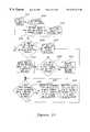
- FIG. 21is a block diagram of the system of FIG. 1 illustrating data flow in the system according to the invention
- FIG. 22is an exemplary screen display of a numeric keypad according to the invention.
- FIGS. 23 and 24are exemplary flow diagrams illustrating the operation of the central processor in the user interface computer for defining operating modes and mode sequences for the system;
- FIGS. 25 and 26are exemplary flow diagrams illustrating the operation of the central processor in the user interface computer for adapting setup files for the system;
- FIGS. 27-30are exemplary screen displays generated by the user interface computer for selecting an operating mode according to the invention.
- FIG. 31is an exemplary flow diagram illustrating the operation of a central processor in the user interface computer for automatically configuring the system
- FIG. 32is a block diagram of an irrigation, aspiration and/or vitrectomy module according to a preferred embodiment of the system of FIG. 1;
- FIG. 33is a block diagram of a phacoemulsification and/or phacofragmentation module according to a preferred embodiment of the system of FIG. 1;
- FIG. 34is a block diagram of an air/fluid exchange, electric scissors and/or forceps module according to a preferred embodiment of the system of FIG. 1;
- FIG. 35is a block diagram of a bipolar coagulation module according to a preferred embodiment of the system of FIG. 1;
- FIG. 36is a block diagram of an illumination module according to a preferred embodiment of the system of FIG. 1;
- FIG. 37is a block diagram of a peripheral foot control circuit according to a preferred embodiment of the system of FIG. 1;
- FIG. 38is a block diagram of a peripheral intravenous pole control circuit according to a preferred embodiment of the system of FIG. 1;
- FIG. 39is a block diagram of a power module according to a preferred embodiment of the system of FIG. 1;
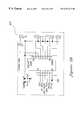
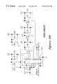
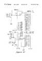
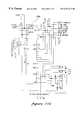
- FIGS. 40-42are schematic diagrams illustrating a communications and power backplane in the base unit of FIGS. 3-8;
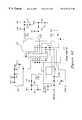
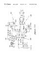
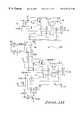
- FIGS. 43-60are schematic diagrams illustrating the irrigation, aspiration and/or vitrectomy module of FIG. 32;
- FIG. 61is a schematic diagram illustrating a cassette detector for use with the irrigation, aspiration and/or vitrectomy module of FIGS. 32 and 43 - 60 ;
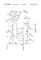
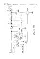
- FIGS. 62-88are schematic diagrams illustrating the phacoemulsification and/or phacofragmentation module of FIG. 33;
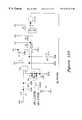
- FIGS. 89-103are schematic diagrams illustrating the air/fluid exchange, electric scissors and/or forceps module of FIG. 34;
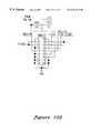
- FIGS. 104-113are schematic diagrams illustrating the bipolar coagulation module of FIG. 19;
- FIGS. 114-125are schematic diagrams illustrating the illumination module of FIG. 36;
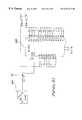
- FIGS. 126-136are schematic diagrams illustrating the foot control circuit of FIG. 37;
- FIGS. 137-146are schematic diagrams illustrating the intravenous pole control circuit of FIG. 38.
- FIGS. 147 and 148are schematic diagrams illustrating a pressure sensing circuit for use with a scroll pump according to an alternative embodiment of the irrigation, aspiration and/or vitrectomy module of FIGS. 32 and 43 - 60 ;
- FIGS. 149 and 150are schematic diagrams illustrating the power module of FIG. 39 for providing power to the backplane of FIGS. 40 - 42 .
- FIG. 1illustrates a microsurgical control system, generally designated 1 , according to a preferred embodiment of the present invention.
- the system 1includes a computer unit 3 having a flat panel display 5 , a base unit 7 housing a plurality of modules 13 , and peripherals such as a foot control assembly 15 and a motorized intravenous (IV) pole assembly 17 (each of which is generally indicated by its respective reference numeral).
- Each of the modules 13 housed in the base unit 7controls at least one ophthalmic microsurgical instrument 19 for use by a surgeon in performing various ophthalmic surgical procedures.
- ophthalmic microsurgeryinvolves the use of a number of different instruments 19 for performing different functions.
- These instruments 19include vitrectomy cutters, phacoemulsification or phacofragmentation handpieces, electric microscissors, fiber optic illumination instruments, coagulation handpieces and other microsurgical instruments known in the art.
- their operating parametersdiffer according to, for example, the particular procedure being performed, the different stages of the procedure, the surgeon's personal preferences, whether the procedure is being performed in the anterior or posterior portion of the patient's eye, and so on.
- an instrumentation cartsupports system 1 .
- the cart 21includes a surgical, or Mayo, tray 25 , the automated IV pole assembly 17 , a storage compartment 27 for stowing the foot control assembly 15 , disposable packs and other items, an opening 33 to house an expansion base unit (not shown in FIG. 1 ), and rotating casters 35 .
- Base unit 7 and computer unit 3preferably sit on top of instrumentation cart 21 as shown in FIG. 1 and the Mayo tray 25 is mounted on an articulating arm (not shown) preferably attached to the top of instrumentation cart 21 , directly beneath base unit 7 .
- Instrumentation cart 21also holds a remote control transmitter, generally indicated 39 , for use in remotely controlling system 1 .
- the modules 13 in base unit 7house control circuits for the various microsurgical instruments 19 so that the system's user is able to configure system 1 for optimizing its use by the surgeon.
- modules 13include connections or ports by which one or more microsurgical instruments 19 connect to each module 13 and house the necessary control circuitry for controlling operation of the particular instrument or instruments 19 connected thereto.
- the userby inserting the desired modules 13 in base unit 7 , configures system 1 to meet a particular surgeon's preference, to control each of the instruments 19 needed for a particular surgical procedure, or to otherwise optimize system 1 for use by the surgeon.
- foot control assembly 15 and IV pole assembly 17include electronic control circuits for controlling their operation.
- each of the modules 13 , and the control circuits for each of the peripherals, namely, foot control assembly 15 and IV pole assembly 17 ,constitute nodes on a computer network.
- the computer networkprovides power distribution and peer-to-peer data communication between the nodes.
- base unit 7includes a number of modules 13 which control various microsurgical instruments 19 typically used in performing ophthalmic surgical procedures.
- each module 13controls one or more surgical instruments 19 connected to it.
- a power bus and a data communications buseach positioned on a backplane 101 (shown in detail in FIGS. 5 and 40 - 42 ), connect modules 13 to each other.
- modules 13engage the backplane 101 via a connector (e.g., connector 171 in FIG. 10) at the rear of each module 13 .
- backplane 101provides power distribution between modules 13 as well as data communication between modules 13 and between modules 13 and computer unit 3 .
- modules 13also include a power module 103 housed by base unit 7 which is connected to both an external AC power source and backplane 101 .
- the power module 103provides power to backplane 101 and, thus, provides power to system 1 .
- a control circuit 105controls foot control assembly 15 and a control circuit 107 (see FIGS. 38 and 137 - 146 ) controls IV pole assembly 17 .
- computer unit 3each module 13 and the control circuits 105 , 107 for the peripherals constitute nodes on a computer network.
- the computer networkprovides peer-to-peer data communication between the nodes.
- each module 13is able to communicate directly with the other modules 13 , the peripherals and computer unit 3 .
- system 1provides modular control of several different instruments 19 as well as user-configurability.
- the base unit 7forms a rack having positions or slots for receiving a plurality of modules 13 which electronically control the operation of surgical instruments 19 used by a surgeon in performing ophthalmic surgical procedures.
- the base unit 7includes a chassis (generally designated 109 ), a top cover 111 having the shape of an inverted channel, and a front cover or bezel 113 which may be removed as shown in FIG. 4 for inserting and removing modules 13 .
- the front cover 113is fastened in place, the rearward wall 115 of the cover holds the modules in place within the base unit 7 thereby forming a retainer for retaining the modules in the rack.
- the front cover 113is held in place by two fasteners (not shown) screwed into threaded holes 117 in the front of the chassis 109 . In the alternative, front cover 113 clips in place.
- the top cover 111includes four circular receptacles 119 for receiving feet on the bottom of computer unit 3 . Each of these receptacles 119 is tapered to conform to the shape of the computer unit feet and to center the feet in the receptacles.
- the chassis 109comprises a rear panel 121 integrally formed with a bottom panel 123 .
- the bottom panel 123extends perpendicular to the front plane (i.e., the front surface) of the backplane 101 which is fastened to the rear panel 121 with fasteners 125 .
- Ten 18-pin female electrical connectors 127are provided on the front surface of the backplane 101 .
- the three left-most connectors 127 as shown in FIG. 5are spaced at three inch intervals, and the remaining connectors 127 are spaced at 1.5 inch intervals.
- Each socket of each connector 127is connected in parallel to the similarly positioned sockets of the other connectors thereby forming the aforementioned power and data communications buses.
- Louvers 131are provided in the rear panel 121 above the backplane 101 for permitting air to escape from the base unit 7 (FIG. 5 ).
- a generally rectangular opening 133extends through the rear panel 121 below the backplane 101 to provide access for a 3-prong connector on the back of the power module 103 as will be explained below.
- a circular opening 135is provided in the rear panel 121 for accepting a pneumatic quick disconnect coupling (not shown) on the back of an irrigation/aspiration/vitrectomy (IAV) (e.g., module 321 in FIGS. 32 and 43 - 60 ).
- IAVirrigation/aspiration/vitrectomy
- Thirteen parallel rails, each generally designated by 137are attached to the bottom panel 123 by fasteners 139 (FIG. 6 ).
- the rails 137are evenly spaced at 1.5 inch intervals and extend perpendicular to the front of the backplane 101 .
- One or more of the rails 137is used to guide the modules 13 into position in the base unit 7 so they are properly aligned for connection with the backplane 101 .
- each of the rails 137has an I-shaped cross-section comprising upper and lower horizontal flanges ( 141 , 143 , respectively) joined by a vertical web 145 .
- FIG. 5shows four feet 141 extend down from the bottom panel 123 and are sized to seat in depressions (not shown) molded in the cart 21 .
- an intake grating 153is provided in the bottom panel 123 for permitting air to enter the base unit 7 to cool the modules 13 .
- FIG. 7shows two circular 9-pin female electrical connectors 157 mounted on the back face of the rear panel 121 . Each of these connectors 157 is connected in parallel to the data communications bus on the backplane 101 to communicate with peripherals such as the cart 21 (including IV pole assembly 17 ), the computer unit 3 or the foot control assembly 15 .
- the connectors 157may also be used to connect base unit 7 to a separate expansion base unit as will be explained in detail below.
- the connectors of the preferred embodimentare Series 703 electrical connectors sold by Amphenol Corporation of Wallingford, Conn.
- FIGS. 9-11illustrate exemplary modules 13 for electronically controlling the operation of surgical instruments 19 used by a surgeon in performing ophthalmic surgical procedures.
- the exemplary module shown in FIG. 9is the power module 103 for supplying power to the power bus of the backplane 101 .
- Each of the modules 13comprises a case 161 formed from aluminum sheet and a molded plastic front cover 163 .
- certain modules 13have one or more ports provided in their front covers 163 for connecting various surgical instruments (not shown) to the modules.
- the power module 103 illustrated in FIG. 9is three inches wide. Other modules have other widths which are multiples of 1.5 inches (e.g., 1.5 inches or 4.5 inches).
- Each of the modules 13has a green light emitting diode (LED) 165 , or other visual indicator, mounted on the front cover 163 to indicate when the module is active.
- LEDgreen light emitting diode
- each module 13includes an 18-pin male electrical connector 171 adapted to connect to any of the female connectors 127 mounted on the backplane 101 .
- the connector 171is recessed in the case 161 to protect the connector and to maximize the space provided within the base unit 7 .
- a cooling fan 173is positioned adjacent an exhaust port 175 provided in the rearward face of the module case 161 above the 18-pin connector 171 for exhausting air from the case 161 to cool components within the module 13 .
- a recess 177is formed in the bottom of the front cover 163 for gripping the module 13 to slide it into and out of the base unit 7 .
- An opening 179is provided in the bottom of the module case 161 to permit air to enter the module when the fan 173 is energized to cool components housed within the module 13 .
- One or more slots 181are formed in the bottom wall 183 of each module case 161 . Each of these slots 181 extends from a rear wall 185 of the case 161 and is configured to receive one of the guide rails 139 on the bottom panel 123 of the base unit chassis 109 to guide the module 13 and align its connector 171 with the corresponding connector 127 on the backplane 101 .
- the rails 137 and slots 181form a guide for guiding each of the modules 13 into the rack so the respective module connector 127 is aligned for connection to the bus.
- a channel 187is tack welded to the bottom wall 183 of the module case 161 above each slot 181 to prevent debris from entering the case through the slots 181 and to shield the electronic components housed within the case from electromagnetic interference.
- the rails 137 and slots 181are sized to permit some movement (e.g. ⁇ fraction (1/16) ⁇ inch) between the module 13 and base unit 7 so the pins of the module connector 171 can properly align with the sockets of the backplane connector 127 .
- the connectors 127 , 171are tapered to guide the pins into the sockets even though the connectors are initially out of alignment by some amount (e.g., 0.1 inch).
- the rails 137 and slotsare dimensioned to allow some movement, they do not permit any more misalignment than the connectors will tolerate. Therefore, the rails 137 and slots 181 adequately provide for piece-part tolerances, but guide each of the modules 13 into the rack so the respective module connector 127 is aligned for connection to the bus.
- Portions of the bottom wall 183 of the module case 161 adjacent each slotare engageable with the top of the lower flange 143 of a respective rail 137 to space the case 161 from the base unit chassis 109 and minimize metal-to-metal contact between the modules 13 and base unit 7 .
- two slots 181are present in the exemplary module 13 shown in FIG. 11, one or more slots may be present in other modules depending upon their widths. For instance, 1.5 inch wide modules 13 have one slot 181 and 4.5 inch wide modules have three slots.
- the exhaust port 175 and fan 173align with the louvers 131 in the base unit rear panel 121 as shown in FIG. 13 to freely vent air from the module when the cooling fan is energized.
- the intake opening 179 of the modulealigns with the grating 153 in the base unit bottom panel 123 to allow air to enter the module 13 from outside the base unit 7 .
- Each module 13also provides overcurrent protection to ensure that a single module failure does not damage other parts of the system 1 .
- the front cover 163 of each module 13includes beveled surfaces 191 extending rearwardly from the front surface 193 along opposite sides of the front surface.
- the bevelled surfaces 191are convergent with respect to one another toward the front surface 193 so that when the module 13 is placed in the base unit 7 beside another module, with a bevelled surface of one module adjacent a bevelled surface of the other module, the generally planar front surfaces of the adjacent modules are laterally spaced from one another by a distance D.
- the lateral spacing between the module front surfacesreduces the “noticeability” of any misalignment between the front surfaces 193 of adjacent modules. Thus, greater piece part. tolerances are permitted without detracting from the appearance of the system 1 .
- the module connectors 171connect to the connectors 127 on the backplane 101 when the modules 13 are installed in the base unit 7 .
- the male and female connectorsWhen the male and female connectors are connected, appropriate circuits within the module 13 are connected to the power and data communications buses in the backplane 101 .
- the same module circuitsconnect to the same circuits of the power and data communications buses.
- the modules 13are generally interchangeable and may be ordered in any sequence within the base unit 7 .
- each module 13is separately controlled, only those modules which control instruments necessary for a particular surgical procedure need be installed in the base unit 7 . Therefore, the previously described rack is configured to receive the modules 13 in a plurality of different positions along the power and data communications buses so that they are selectively organizable in a plurality of different sequences in the rack.
- the power module 103has a dedicated location within the base unit 7 so it may be conveniently connected to the external power source through the rectangular opening 133 in the base unit rear panel 121 . Because the power module 103 is 3 inches wide, the spacing between the two left-most connectors 127 as shown in FIG. 5 is three inches. The spacing between the second and third connectors from the left as shown in FIG. 5 permit either a three or 4.5 inch wide module to be inserted next to the power module 103 . If an IAV (e.g., module 321 in FIGS. 32 and 43 - 60 ) is used, it must be installed over the three right-most rails 137 as shown in FIG. 5 .
- IAVe.g., module 321 in FIGS. 32 and 43 - 60
- a pneumatic quick disconnect couplingprotrudes from the back of the IAV module 321 .
- the IAV module 321can only be installed in the right-most position because the coupling must extend through the circular opening 135 in the rear panel 121 of the base unit 7 . If an IAV module is not being used, any other module (besides a power module) may be installed in the right-most position.
- the modules 13are fully interchangeable and may be installed in any order as desired.
- the base unit 7is configured so the modules 13 may be received in a plurality of different positions within the rack and so they are selectively organizable in a plurality of different sequences in the rack.
- All the modules 13are capable of being installed into or removed from base unit 7 quickly from the front without the aid of any tools due to their modular construction and the releasable engagement of the backplane 101 .
- This quick installation and removalfacilitates convenient maintenance or replacement of modules. For example, if a particular module 13 needs repair, it can be easily removed and shipped to a repair facility. During repair, another module may be used in its place or the system 1 can be operated without the particular module 13 .
- a post 195extends from the rear face of the front cover 113 of the base unit 7 .
- the post 195is positioned on the front cover so it engages a opening 197 (FIG. 9) in the power module 103 when the cover is installed on the base unit with the modules 13 installed.
- An interlock switche.g., interlock switch 783 in FIG. 39 located behind the opening 197 in the power supply module 103 interrupts power to each of modules 13 upon removal of the base unit front cover 113 .
- userscannot contact the backplane 101 when it is energized.
- the particular configuration of modules in the rackis checked during each start-up (as explained below with respect to FIG. 31 ), and cannot be changed without removing the front cover 113 . By interrupting power when the cover 113 is removed, the configuration of the modules 13 cannot be changed without being detected.
- the system 1may further include an expansion connector 203 (see FIG. 16) for connecting the base unit 7 to an optional expansion base unit 207 thereby to expand the network.
- the expansion base unit 207is substantially identical to base unit 7 .
- the usercan expand the network and, thus, expand the operating capabilities of the system 1 , by connecting either 9-pin connector 157 on the rear panel 121 of the base unit 7 to the similar connector on the expansion base unit 207 with the expansion connector 203 .
- the expansion base unit 207 of the preferred embodimentincludes its own power module 211 . Therefore, the expansion connector 203 connects the data communication buses of the units, but not the power buses.
- a single power modulecould supply both units without departing from the scope of the present invention.
- poweris provided to the expansion base unit 207 via the expansion connector 203 by connecting the power bus on the backplane 101 of the base unit 7 to the power bus on the backplane 209 of the expansion base unit 207 .
- the data communications buspreferably comprises a twisted pair cable 215 having a first wire 217 and a second wire 219 .
- the computer network linking each of the components of system 1is of the type sold by Echelon Corporation under the trademark LONTALK® utilizing an RS485 communications protocol.
- the RS485 standardprovides a platform for multi-point data transmission over a balanced twisted pair transmission line.
- Each module 13includes an RS485 transceiver 223 for receiving data from and transmitting data to the data communications bus and a processor 225 coupled to the transceiver 223 .
- Motorolamanufactures a suitable processor 225 designated NEURON® chip Model No. MC143150 and National Semiconductor manufactures a suitable transceiver 223 designated chip Model No. 75156.
- the data communications bus, the transceivers 223 and the processors 225together form the communications network by which modules 13 , computer unit 3 , the control circuit 105 of foot control assembly 15 and the control circuit 107 of IV pole assembly 17 communicate with each other.
- system 1provides peer-to-peer communication between its components.
- processor 225is also referred to herein as a “neuron” or “neuron processor” (NEURON® is a registered trademark of Echelon Corporation).
- Each neuron processor 225preferably comprises three 8-bit on-board processors. Two of the three on-board processors implement a communication subsystem, enabling the transfer of information from node to node on the network. The third on-board processor executes an embedded application program.
- neuron processors 225control microsurgical instruments 19 connected thereto.
- the neuron processors 225 of modules 13receive the data communicated via the data communications bus and, in response to the data, generate control signals to control microsurgical instruments 19 .
- transceivers 223tap into the first and second wires 217 , 219 of twisted pair cable 215 .
- twisted pair cable 215is positioned on backplane 101 (i.e., as traces on backplane 101 ).
- backplane 101also includes a pair of additional data cable connectors 157 for connecting data cables to backplane 101 .
- the data cablesinclude twisted pair cable and extend the data communications bus from backplane 101 to computer unit 3 and to the peripherals. For example, one data cable runs from one data cable connector 157 to computer unit 3 and another data cable runs from the other data cable connectors 157 to either foot control assembly 15 directly or to IV pole assembly 17 and foot control assembly 17 via instrumentation cart 21 .
- each end of twisted pair cable 215must be terminated by a resistance, such as a 120 ⁇ resistor.
- a resistancesuch as a 120 ⁇ resistor.
- the present inventionprovides a termination circuit 229 , shown in FIG. 16, located at one end of twisted pair cable 215 for selectively terminating the network by a 120 ohm resistor and allowing for easy expansion of the network.
- FIG. 16illustrates the termination circuit 229 for selectively terminating the data communications bus.
- the data communications busi.e., twisted pair cable 215
- the data communications busis represented by RS485-HI and RS485-LO lines.
- termination circuit 229is part of expansion connector 203 and is connected in series between the ends of the first and second wires 217 , 219 of the first twisted pair cable 215 .
- termination circuit 229comprises a normally closed switch 231 connected in series with the 120 ohm resistance for terminating the data communications bus.
- the userconnects an expansion cable 233 having a second twisted pair cable 235 associated with expansion base unit 207 to expansion connector 203 .
- the second twisted pair cable 235has a first wire 237 and a second wire 239 provided for connection to termination circuit 229 .
- second twisted pair 235is positioned on backplane 209 and constitutes the data communications bus for expansion unit 207 .
- Termination circuit 229also includes a coil 243 connected to a positive voltage supply.
- the coil 243When the user connects expansion cable 233 associated with expansion base unit 207 to expansion connector 203 , the coil 243 is shorted to ground. As a result, the positive voltage energizes coil 243 which in turn opens the normally closed switch 231 .
- switch 231opens to remove the termination. The termination is then found at the other end of expansion base unit 207 .
- either the expansion cable 233 or the backplane 209 of expansion base unit 207also includes termination circuit 229 .
- FIG. 16also shows lines labeled RESET-HI and RESET-LO.
- computer unit 3communicates a reset signal via the data communications bus to the modules 13 installed in base unit 7 via backplane 101 and to the modules 13 installed in expansion base unit 207 via backplane 209 .
- expansion base unit 207includes its own power module 211 As such, power is not distributed between base unit 7 and expansion base unit 207 .
- the power busmay also be positioned on backplanes 101 , 209 for distributing power from power module 103 to each of the modules 13 of system 1 which are located in either base unit 7 or expansion base unit 207 .
- computer unit 3comprises an embedded central processing computer 245 , at least one disk drive 247 and an internal hard drive 249 .
- the central processor 245 of computer unit 3is an IBM compatible microprocessor-based board including, for example, an Intel 486® or Pentium® processor, and having an industry standard AT motherboard.
- the disk drive 247is a conventional 3.5 inch, 1.44 MB floppy drive and the hard drive 249 is a conventional IDE 3.5 inch internal hard drive having at least 250 MB of memory.
- computer unit 3includes a CD-ROM drive 251 in addition to floppy drive 247 .
- Computer unit 3also includes the flat panel display 5 , a touch-responsive screen 255 for use with flat panel display 5 and various multimedia hardware accessories such as a video board, or display driver 259 , a sound board 261 and speakers 263 .
- each of the various expansion boards of computer unit 3are compatible with standard PC architectures.
- Computer unit 3constitutes a user interface by which the user (such as a surgeon, medical technician or assistant) receives information representative of the various operating parameters of microsurgical instruments 19 and peripherals which provide the different functions needed to perform the surgical procedures.
- the useralso provides information to system 1 via a graphical user interface provided by computer unit 3 .
- the hard drive 249 of computer unit 3stores programmable operating parameters for each of the microsurgical instruments 19 and peripherals.
- the useris able to reprogram or select from the operating parameters stored in hard drive 249 .
- Computer unit 3then communicates the operating parameters to modules 13 as well as to foot assembly 15 and IV pole assembly 17 via the backplane 101 and external data cables and its network. In this manner, the user is able to optimize the performance of instruments 19 during surgery.
- the userstores data representative of a plurality of operating parameters on a removable memory, such as a floppy disk, for use with the disk drive 247 of computer unit 3 .
- the central processor 245 of computer unit 3defines a set of operating parameters for the microsurgical instruments 19 and peripherals based on the data stored in the removable memory.
- the set of operating parameters defined by central processor 245comprise an individualized set of surgeon-selected operating parameters.
- the hard drive 249 of computer unit 3stores default operating parameters which may be adapted to approximate the individualized set of parameters provided by the user.
- operating parametersdefine one or more of the following for use in controlling the various instruments 19 : a linearly variable scissors cut rate; a fixed scissors cut rate; a single actuation scissors cut; a proportional actuation scissors closure level; an air/fluid pressure; an air/fluid flow rate; a linearly variable bipolar power level; a fixed bipolar power level; an illumination intensity level; an aspiration vacuum pressure level; an aspiration flow rate; a linearly variable vitrectomy cut rate; a fixed vitrectomy cut rate; a single actuation vitrectomy cut; a phacoemulsification power level; a phacofragmentation power level; a phacoemulsification pulse rate; and a phacofragmentation pulse rate.
- the control circuits 105 , 107 of the peripheralsalso form nodes on the computer network and operate as a function of at least one operating parameter.
- the operating parametersalso define one or more of following for the peripherals: a plurality of foot control pitch detent levels; and an intravenous pole height.
- computer unit 3also includes an infrared (IR) receiver circuit 267 for receiving IR signals from the hand-held remote control 39 .
- the IR signalspreferably represent commands for controlling operation of system 1 .
- remote control 39is a wireless infrared transmitter similar in size and appearance to a standard television or video cassette recorder remote.
- the unitprovides line of sight operation and preferably uses a transmitter/receiver encoding scheme to minimize the risk of interference from other infrared transmitters and/or receivers.
- the keypad of remote control 39preferably includes control buttons for varying the levels of aspiration, bipolar coagulation power and ultrasound power (for phacoemulsification and phacofragmentation) as well as for varying the IV pole height, turning on and off the illumination instrument and varying the intensity level of the light provided by the illumination instrument.
- remote control 39also includes control buttons for proceeding to the next mode and for returning to the previous mode in a predefined sequence of operational modes.
- computer unit 3includes a network board 271 designed specifically for use in microsurgical system 1 .
- This application specific network board 271includes transceiver 223 and neuron processor 225 for connecting computer unit 3 to the network.
- network board 271is used to interface central processor 245 with the touch-responsive screen 255 and the IR receiver 267 as well as surgical modules 13 , foot control assembly 15 and IV pole assembly 17 .
- the central processor 245 of computer unit 3cooperates with each of the neuron processors 225 of the individual control circuits of modules 13 , foot control assembly 15 and/or IV pole assembly 17 to execute software in a two-tier software hierarchy.
- the first tier of the software hierarchyis the user interface which provides an interface between the user (i.e., the surgical team) and microsurgical system 1 of the invention.
- the term “user interface”refers generally to computer unit 3 and specifically to the routines executed by computer unit 3 to generate a series of functional screen displays which enable the user to interface with system 1 .
- the user interfacedisplays operating parameters and their settings as well as other conditions on flat panel display 5 .
- the user interfacealso receives input from touch-responsive screen 255 , foot control assembly 15 or IR remote control 39 to tailor the operation of system 1 to the surgeon's current surgical procedure.
- the user interfaceis a Microsoft® Windows '95 based environment providing a highly graphical, user friendly operating environment which generates icons, symbols, and the like. As a result, the user interface simplifies the use of system 1 and is particularly well-suited for use with touch-responsive screen 255 .
- the second tier of the system softwareis an embedded control environment used by modules 13 , control circuit 105 and control circuit 107 .
- each component of system 1forms part of a computer network such that the user interface communicates with the embedded software via a predetermined communication architecture such as the communication architecture Echelon LONTALK®.
- each of the modules 13 and peripheralsoperate independently of the other modules 13 and peripherals while still being linked by the network. Thus, the failure of one component will not affect the functionality of the other components of system 1 .
- each module 13 and peripheralincorporates built-in-tests so that specific failures can be identified and reported to computer unit 3 and, thus, be reported to the user.
- the operational status of each module 13 and peripheralis continually checked during operation through the use of a software watchdog timer (e.g., see watchdog timer 475 in FIG. 32 ).
- computer unit 3is especially well-suited for use in a modular system such as system 1 .
- Hard drive 249stores the various programs for operating system 1 , including the programs normally resident in modules 13 .
- the usermay download the appropriate resident program from hard drive 249 to module 13 via the network thereby facilitating its reprogramming.
- Floppy drive 247also allows the user to install software updates or application specific software for use with new modules based on this product. In this manner, the software of system 1 follows a modular approach which parallels the modular design of the hardware. Additionally, the user may save, load and transport user settings from system 1 to another like microsurgical system at a different location through the use of floppy drive 247 .
- Computer unit 3employs sound board 261 and speakers 263 to generate audio signals for warning messages, alarms or other audible indications.
- sound board 261 and speakers 263cooperate with the video board 259 and the CD-ROM drive 251 to provide audio/visual, or multimedia, presentations such as animated on-line service and instruction manuals, operational demonstrations, and the like in a number of different languages.
- Flat panel display 5 and touch-responsive screen 255are the primary means of interface between system 1 and the user.
- flat panel display 5is an active matrix liquid crystal display (LCD) (10.4′′ diagonal, VGA resolution, active matrix LCD, 256 colors) overlaid by touch-responsive screen 255 .
- LCDliquid crystal display
- touch-responsive screen 255is an analog resistive touch screen which is chemically resistant to common sterilizing solutions and housed in a watertight bezel.
- computer unit 3also includes a separate power supply 275 .
- the power module 10:3 of base unit 7provides power to computer unit 3 .
- FIG. 19illustrates the application specific network board 271 of computer unit 3 .
- network board 271includes an RS485 network connector circuit 277 as well as a network manager/controller circuit 279 and an RS485 termination circuit 281 .
- the circuits 277 , 279 , 281provide a network interface for computer unit 3 to communicate via the data communications bus.
- Network board 271further includes an ISA bus connector 283 , an ISA bus transceiver 285 and an ISA bus interface circuit 287 , such as an electronically programmable logic device (EPLD).
- the circuit 283 , 285 , 287provide an interface between network board 271 and central processor 245 .
- EPLDelectronically programmable logic device
- network board 271provides circuit connections and interfaces for touch-responsive screen 215 , flat panel display 5 and IR remote control 39 .
- network board 271includes a touchscreen controller/encoder 289 connected to central processor 245 via a serial connector 291 and connected to flat panel display 5 via a flex-circuit connector 293 .
- the flex-circuit connector 293also connects a backlight brightness control 295 to flat panel display 5 and connects the IR receiver 267 to an IR remote decoder circuit 297 .
- Network board 271also includes a brightness control connector 299 for use with an encoder knob (not shown) on computer unit 3 by which the user controls the intensity of flat panel display 5 .
- remote control 39also provides a means for varying the display intensity so the input received at the brightness control connector is routed through the IR remote decoder 297 to the bus interface circuit 287 .
- bus interface circuit 287provides the necessary control signals to the brightness control 295 for varying the intensity of flat panel display 5 .
- network board 271further includes a watchdog timer and reset circuit 301 in a preferred embodiment of the invention.
- termination circuit 281is shown in schematic diagram form.
- network board 271provides termination circuit 281 for selectively terminating the computer unit end of the data communications bus.
- termination circuit 281comprises a normally closed switch 303 connected in series with an approximately 120 ohm resistance.
- the userconnects an expansion cable (not shown) from a peripheral to either a first jumper 305 or a second jumper 307 .
- the jumpers 303 , 305preferably provide means for connecting additional peripherals to the network of system 1 .
- the usercan connect foot control assembly 15 or some other peripheral to the network via a connector (not shown) associated with either jumper 305 , 307 instead of via connector 157 .
- the expansion cables from the peripherals that are to be connected to the networkshort a pair of termination switch pins on jumpers 305 , 307 .
- a peripheral expansion cable connected to jumper 305causes a short circuit between TERM SWITCH 1 A and TERM SWITCH 1 B.
- a peripheral expansion cable connected to jumper 307causes a short circuit between TERM SWITCH 2 A and TERM SWITCH 2 B.
- termination circuit 281also includes a coil 309 connected to a positive voltage supply.
- the coil 309is shorted to ground and, thus, energized when both TERM SWITCH 1 A and 1 B and TERM SWITCH 2 A and 2 B are shorted.
- the normally closed switch 303opens to remove the termination. The termination is then found at the peripheral end of the data communications bus.
- FIG. 21illustrates data flow in system 1 according to one preferred embodiment of the invention.
- each module 13 installed in base unit 7controls one or more microsurgical instruments 19 for providing several different surgical functions.
- instruments 19provide intraocular pressure (IOP), scissors cutting, forceps control, ultrasound (e.g., for phacoemulsification or phacofragmentation), irrigation, aspiration, vitrectomy cutting, bipolar coagulation and/or illumination.
- modules 13include a venturi IAV module 321 and a scroll IAV module 323 , both of which control irrigation, aspiration and vitrectomy functions of system 1 .
- the venturi IAV module 321is for use with a venturi pump whereas the scroll IAV module 323 is for use with a scroll pump.
- Modules 13also include a phaco module 325 controlling phacoemulsification and phacofragmentation functions and a scissors module 327 controlling a scissors cutting function.
- the scissors module 327also controls a forceps function and includes air/fluid exchange control circuitry for controlling an IOP function.
- modules 13further include a coagulation module 329 controlling a bipolar coagulation function and an illumination module 331 controlling an illumination function.
- This embodiment of the inventionalso includes foot control circuit 105 and IV pole control circuit 107 as peripherals connected to the network of system 1 .
- venturi IAV module 321 , scroll IAV module 323 , phaco module 325 , scissors module 327 , coagulation module 329 and illumination module 331as well as the control circuits 105 , 107 for foot control assembly 15 and IV pole assembly 17 , respectively, each constitute nodes on the network.
- the usereither programs the operating parameters, selects them from a set of default operating parameters or inputs them directly from the user interface to optimize performance of the surgery.
- computer unit 3in turn communicates the operating parameters to modules 13 via line 335 .
- Each active module 13then provides control signals as a function of at least one of the user-entered or default operating parameters for controlling the microsurgical instrument or instruments 19 connected thereto.
- computer unit 3provides on/off control of a number of instruments 19 and IV pole assembly 17 via line 337 and receives feedback regarding their operational status via line 339 .
- the control circuit 105 of foot control assembly 15provides both linear control (e.g., by its foot pedal) via line 341 and discrete control (e.g., by its push-buttons) via line 343 of the various modules 13 . Further, with its programmable function button, foot control assembly 15 also provides control of system 1 based on instructions from computer unit 3 .
- the data communications bus of the inventioncarries the data communicated by lines 335 , 337 , 339 , 341 and 343 .
- the data communications busis a bi-directional serial bus which carries all types of signals.
- the lines 335 , 337 , 339 , 341 , 343represent data flow in system 1 but do not represent the data communications bus.
- the network of system 1provides peer-to-peer communication between its nodes. For example, it may be desirable to disable the user interface when foot control assembly 15 is engaged. In other words, the user is prevented from changing the operating parameters of instruments 19 when the surgeon is using foot control assembly 15 to remotely control instruments 19 . In this instance, foot control assembly 15 communicates via the network directly with the user interface and the other modules 13 to provide peer-to-peer communication. Similarly, it may be desirable to prevent certain instruments 19 from operating simultaneously for safety reasons. For example, the phacoemulsification instrument is disabled by the bipolar coagulation instrument when the latter is being used and vice-versa. In contrast, the aspiration function is needed during phacoemulsification or phacofragmentation. Thus, information regarding both functions is communicated via the network between the phaco module 325 and either venturi IAV module 321 or scroll IAV module 323 .
- an opening screen display at start-upallows the user to select the various surgical functions available for either the anterior or posterior portions of the patient's eye or to select a utilities program for programming system 1 or for performing other setup functions.
- computer unit 3When the user selects either the anterior portion or the posterior portion, computer unit 3 preferably displays a surgeon selection menu on flat panel display 5 .
- hard drive 249stores an individualized set of initial operating parameters for each surgeon listed on the menu.
- computer unit 3sets the operating portion to either anterior or posterior with the appropriate set of initial operating parameters depending on the user's selections. If a particular surgeon is not listed on the menu, computer unit 3 sets the operating portion to either anterior or posterior with the default operating parameters. If desired, the surgeon may then change the operating parameters from their default values.
- computer unit 3displays a utilities screen on flat panel display 5 when the user selects the utilities option from the opening screen.
- computer unit 3sets the operating mode to “none”.
- the utilities programallows the user to modify the various system settings (e.g., modify or add new surgeons to the surgeon selection menu, modify initial operating parameters previously saved or add new initial operating parameters, and access user help information).
- the user interfaceestablishes dedicated portions of touch-responsive screen 255 for different selection or information windows. For example, primary windows are generated for displaying aspiration, phacoemulsification, phacofragmentation, vitrectomy, scissors and linear coagulation functions. Secondary windows are then available to the user for displaying non-linear coagulation, IOP, illumination, IV pole and the foot control configuration functions.
- the user interfacealso employs a series of selection tabs (see FIG. 27) which allow the user to select the current operating mode of system 1 , activate or deactivate surgical functions (e.g., coagulation), display on-line help and to exit system 1 . If needed, the user selection tabs also include multiple choices for one or more of the selections and expand to display these additional selections.
- the usermay customize the different operating parameters to meet a surgeon's particular preferences through the use of a surgical function interface of the user interface.
- the surgical function interfaceuses a number of displays to represent the various microsurgical system functions (e.g., venturi vacuum, scroll vacuum, vitrectomy, ultrasound, coagulation, scissors cutting, illumination and so forth) which are active.
- the surgical function interfacedisplays current operating parameters numerically or graphically, displays operating set points and/or displays the on or off status of the various functions.
- the central processor 245 of computer unit 3also executes routines to generate various control icons for use in adjusting the different operating parameters and/or for use in turning the functions on or off.
- the interfaceprovides a spin button, or up/down, control for incrementing or decrementing the current vacuum operating parameter.
- the interfacealso uses push-button controls for commanding a number of functions. For example, during performance of the aspiration function, the surgeon typically primes the aspiration line before proceeding to first remove any air in the line.
- the priming functionis preferably indicated on the screen by a push-button.
- the interfacealso utilizes progress bars for showing current operating parameters with respect to their preset minimum and maximum values. For example, if the ultrasound power level is at 20% of the maximum power level during phacofragmentation, a progress bar covers 20% of a window labeled 0% on its left edge and 100% on its right edge.
- central processor 245preferably executes a calculator function interface in response to the user touching the portion of touch-responsive screen 255 corresponding to the numerical display of one of the operating parameter values.
- the calculator function interfacepreferably causes flat panel display 5 to display a numeric keypad, generally indicated 347 , as part of the touch-responsive screen 255 for use in entering a desired value of the selected operating parameter rather than incrementing or decrementing the value via a spin button control.
- the usermay quickly and easily change the numerical surgical settings without repeatedly or continuously pressing the up or down arrow of the spin button control.
- the interfacedisplays the particular value entered via the keypad 347 in a window 349 with a legend indicating the operating parameter being modified (e.g., the maximum vacuum setting).
- Keypad 347further includes a push-button 351 for entering the default; or programmed maximum value, a push-button 353 for entering the default or programmed minimum value and push-buttons 355 , 357 for incrementing or decrementing the value, respectively.
- the calculator function interfaceis disabled during operation of foot control assembly 15 when performing an active operation.
- the user interfaceprovides programming function interfaces to represent the microsurgical system functions for use in programming mode settings.
- the useraccesses the programming function interfaces via the utilities menu described above.
- the programming interfacesdisplay operating set points and provide means for modifying the operating set points for a given operating mode, changing the functions from linear to fixed, or vice-versa, turning the functions on/off for a given operating mode and so forth.
- system 1is a mode-based surgical system.
- a modeis defined to be a surgical setup that includes the use of one or more surgical instruments 19 having specified initial operating parameters.
- Each of the surgical instruments 19 which are active in a particular modeperform one or more surgical functions.
- modeand “function” are sometimes used interchangeably in commonly assigned patents, for example, U.S. Pat. Nos. 4,933,843, 5,157,603, 5,417,246 and 5,455,766, it is to be understood that these terms are distinct as used herein.
- one phacoemulsification modeis defined such that an aspiration instrument provides the vacuum function and a phacoemulsification handpiece provides the ultrasound, or phacoemulsification, function and both of these instruments have specific initial operating parameters.
- the flat panel display 5 of computer unit 3displays information to the user.
- flat panel display 5displays this information in the form of various on-screen menus of options available to the user.
- the menusmay be in the form of lists, labeled push-buttons, user-selectable tabs and the like.
- the userselects one or more of the available options from the on-screen menu by touching a corresponding portion of touch-responsive screen 255 .
- One such displayincludes a menu of the selectable modes.
- the hard drive 249 of computer unit 3stores operating parameters according to predefined surgical operating modes in the form of a collection of setup files.
- each modeis representative of one or more surgical procedures to be performed and defined by operation of at least one of the microsurgical instruments 19 .
- Each modedetermines which instruments 19 are to be used in the particular mode as well as the operating parameters associated with those instruments.
- the usercan modify or define the modes via the user interface.
- FIG. 23is a flow diagram illustrating the operation of computer unit 3 for providing operating modes according to the invention.
- system 1first identifies and initializes each of the modules 13 installed in base unit 7 at power-up.
- central processor 245retrieves a particular setup file corresponding to the selected surgeon at step 365 .
- the retrieved setup filecomprises a mode database having a number of mode records, each being representative of a different mode and the operating parameters for the various surgical functions to be performed by system 1 operating in that mode.
- the setup filemay also include initial values for other operating parameters which are not part of the mode records such as audio levels or other mode-independent settings.
- the retrieved setup filealso includes a mode sequence database which defines a sequence in which certain of the modes are to be provided.
- computer unit 3compares the identification information to the retrieved setup file to verify that the necessary modules 13 are present in system 1 for performing the desired surgical functions specified in the mode records of the mode database. If not, computer unit 3 generates a translated setup file at step 369 by translating or substituting operating parameters for the operating parameters in the retrieved setup file so that it corresponds to the actual modules 13 in base unit 7 . If the necessary modules 13 are present in system 1 , or if computer unit 3 has generated a translated setup file, computer unit 3 determines that the setup file is acceptable at step 371 .
- central processor 245retrieves a set of the operating parameters from hard drive 249 for the microsurgical instrument or instruments 19 to be used in a selected mode and surgical modules 13 control the microsurgical instruments 19 connected thereto as a function of the operating parameters retrieved from memory.
- the mode interfacealso defines a sequence in which the modes are to be active.
- the on-screen menualso includes an option for either proceeding to the next mode in the sequence defined in the mode sequence database or returning to the previous mode in the sequence. This enables the surgeon to proceed from mode to mode by touching a single push-button on touch-responsive screen 255 .
- the surgeoncan also proceed from mode to mode by depressing a particular button on foot control assembly 15 or by depressing a particular button on the hand-held remote control 39 .
- central processor 245retrieves in sequence the set of operating parameters from hard drive 249 for the microsurgical instruments 19 to be used in the selected mode and then retrieves another set of the operating parameters from hard drive 249 for the microsurgical instruments 19 to be used in either the next or the previous mode in the predefined sequence depending on the user's instructions.
- the mode sequence databasemay only define a sequence for some of those modes.
- the mode sequence databasemay define a sequence in which the first mode defined in the mode database is to be followed by the third mode, then the ninth mode and then the seventh mode. In other words, there need not be a one-to-one correspondence between the mode records in the mode database and the modes listed in the mode sequence database.
- FIG. 24illustrates the mode sequencing operation of computer unit 3 in flow diagram form.
- the userenters a mode sequence command via the user interface.
- the mode sequence commandmay be a command to proceed to the next mode in the sequence, to return to the preceding mode in the sequence or to return to the last mode performed.
- computer unit 3identifies the mode record from the mode database which corresponds to the mode in the predefined sequence.
- computer unit 3proceeds to step 379 for instructing each module 13 and peripheral of system 1 of the user's desired mode change. Also at step 379 , computer unit 3 executes certain safety routines.
- surgeonis only permitted to change from mode to mode when the foot pedal of foot control assembly 15 is inactive.
- An exceptionis made for the phacofragmentation, scissors and other modes which may be selected when the foot pedal of foot assembly 15 is active if the irrigation function is operating to provide continuous irrigation.
- computer unitalso proceeds to step 379 after receiving a new mode selection command at step 381 .
- computer unit 3reprograms the operating parameters of the microsurgical instruments 19 to be used in the selected operating mode at step 383 .
- computer unit 3enables or disables the various display components so that the display on flat panel display 5 corresponds to the surgical functions available in the selected mode.
- computer unit 3enables each of the modules 13 or peripherals to be used in the selected operating mode at step 387 .
- Table Ilists exemplary modes and the operating parameters associated with the instruments 19 to be used in each of the modes.
- Table Ilists the mode records of an exemplary mode database.
- the surgeonmay define a mode sequence database via the user interface which includes only some of the nine modes.
- the mode sequence databasedefines a sequence beginning with mode 1 (open), followed by mode 3 (emulsification-medium), followed by mode 9 (dual) and ending with mode 7 (clean II).
- computer unit 3compares the system identification information, built at power-up in the form of a hardware database, to the retrieved setup file. By doing so, computer unit 3 is able to verify that the necessary modules 13 are present in system 1 for performing the desired surgical functions of the modes in the mode database. If not, computer unit 3 generates a translated setup file by translating or substituting operating parameters for the operating parameters in the retrieved setup file so that it corresponds to the actual modules 13 in base unit 7 .
- FIGS. 25 and 26illustrate a preferred means for adapting the setup files according to the invention.
- computer unit 3first examines each mode record in the mode database at step 391 .
- computer unit 3reads a set of communications parameters corresponding to the hardware (i.e., the different modules 13 and control circuits 105 , 107 ) on the network.
- each neuron processor 225 of the various nodes on the networkexecutes embedded programs for controlling the different microsurgical instruments 19 and peripherals.
- the communications parametersrepresent a unique identification label specific to each processor 225 which includes information regarding the type of device being controlled (e.g., vitrectomy handpiece or ultrasound device) and the version of module 13 or peripheral in which the processor 225 is located.
- the identification labelalso includes a specific identifier (e.g., a serial number) which is unique to the particular module 13 or control circuit 105 , 107 .
- a specific identifiere.g., a serial number
- the version of a particular module 13may change as either the hardware or software is updated.
- the mode records in the mode databaseeach represent a different operating mode and the operating parameters for the various surgical functions to be provided by system 1 operating in that mode. As such, the operating parameters correspond to specific nodes on the network by both function and version.
- step 393computer unit 3 determines if the type of hardware needed for each instrument or peripheral to used in the operating mode defined by the mode record is present in system 1 . If so, at step 395 , computer unit 3 determines if the version information for each module 13 and peripheral control circuit 105 , 107 matches the version information specified by the mode record. If the version information is correct, computer unit 3 returns to step 391 for examining the next mode record in the mode database. On the other hand, if the version information is incorrect, computer unit 3 determines at step 397 if the version information for the installed hardware is compatible with the version information specified by the mode record. If compatible, computer unit proceeds to step 399 in which it substitutes the operating parameters associated with the actual hardware of system 1 for the operating parameters set forth in the mode record. If the versions are not compatible, computer unit 3 disallows the particular mode at step 401 . Following either step 399 or step 401 , computer unit 3 returns to step 391 for examining the next mode record in the mode database.
- step 393computer unit 3 determines if hardware is present in system 1 for each instrument or peripheral to used in the operating mode defined by the mode record. If not, computer unit 3 proceeds to step 403 shown in the flow diagram of FIG. 26 .
- step 403computer unit 3 determines if the absent hardware is necessary to the operation of system 1 in the particular mode. If the absent hardware is not needed, computer unit 3 deletes the reference to the absent hardware from the mode record at step 405 and then returns to step 391 of FIG. 25 for proceeding to the next mode record. On the other hand, if the absent hardware is needed, computer unit 3 determines at step 407 if substitute hardware is available.
- step 409computer unit 3 deletes the mode record from the mode database at step 409 and then returns to step 391 for proceeding to the next mode record.
- substitute hardwareis available, computer unit 3 proceeds to step 411 .
- computer unit 3translates the operating parameters in the mode record to correspond to the substitute hardware.
- a particular setup of system 1may include venturi IAV module 321 but not scroll IAV module 323 .
- computer unit 3would substitute the flow aspiration operating parameters for vacuum operating parameters which would approximate a flow aspiration response.
- computer unit 3returns to step 391 .
- computer unit 3examines the mode sequence database of the retrieved setup file. If a mode in the mode sequence is no longer available (i.e., it was deleted at step 409 ), computer unit 3 also deletes the mode from the mode sequence database. In this manner, computer unit 3 adapts the retrieved setup file for use with the particular configuration of system 1 . In other words, computer unit 3 generates a translated setup file.
- the mode records shown above in Table Idefine particular modes in terms of the various procedures performed by the surgeon. For example, the surgeon selects the “open” mode when performing the procedure of opening the patient's eye. It is also contemplated that the operating modes of system 1 are defined in terms of the different surgical functions performed during these procedures. Tables II and III, below, list exemplary modes in the anterior and posterior portions in terms of the different surgical functions.
- Tables IV-IXbelow list exemplary initial operating parameters for the various modes shown in Tables II and III.
- Coagulation switchcontrols coagulation on/off
- IV pole height60 cm (40 cm in capsule polish mode; 50 cm in viscoelastic removal mode)
- Coagulation switchcontrols coagulation on/off
- IV pole height75 cm (80 cm in mode 2 and mode 4)
- Coagulation switchcontrols coagulation on/off
- Coagulation switchcontrols coagulation on/off
- Coagulation switchcontrols coagulation on/off
- IV pole height75 cm (40 cm for single cut)
- Coagulation switchcontrols coagulation on/off
- the userselects one of the various predefined modes described above from top level user selection tabs 415 , an example of which is shown in FIG. 27 for anterior portion operations.
- the tabs 415are positioned at the bottom of touch-responsive screen 255 . Only one mode may be active at a time so computer unit 3 automatically deselects the current operating modes when the user selects one of the user selection tabs.
- the usertouches a phaco mode tab 417 for the available phacoemulsification modes.
- flat panel display 5initially only displays the first four modes (i.e., sculpt, segment removal, sculpt (dual) and seg removal (dual)) when the user touches the phaco modes user selection tab 417 .
- computer unit 3In response to the user touching a tab 419 containing the arrow symbol, computer unit 3 generates an additional menu of available phaco modes (i.e., fixed vacuum, linear vacuum, fixed flow and linear flow) for display on flat panel display 5 .
- the usertouches a tab 421 to select the linear vacuum phaco mode from the menu.
- FIG. 30illustrates an exemplary screen display for the linear vacuum phaco mode. As shown, the vacuum, ultrasound (i.e., phacoemulsification) and coagulation functions are available and active in this mode.
- computer unit 3first identifies and initializes each of the nodes on the network (i.e., modules 13 installed in base unit 7 and control circuits 105 , 107 for foot control assembly 15 and IV pole assembly 17 , respectively).
- the central processor 245 of computer unit 3executes software which constitutes a system engine having three operational components: power-up initialization, network management and network liaison.
- the initialization component of the system enginecreates and starts the network.
- the network management componentprovides binding/unbinding of network variables for modules 13 on the network to implement user-selected modes, monitors modules 13 for functionality and processes incoming messages from the network.
- the network liaison componentprocesses the configuration file and mode changes and notifies the user interface of display changes and error occurrences.
- FIG. 31illustrates the operation of computer unit 3 executing the initialization component of the system engine at power-up of system 1 .
- the system engineidentifies each of the nodes on the network and creates a programming object for each node's neuron processor 225 that contains local network variables by which the user interface accesses the node.
- the system engineinitializes a network database stored in the hard drive 249 of computer unit 3 .
- each neuron processor 225 of the various nodes on the networkexecutes embedded programs for controlling the different microsurgical instruments 19 and peripherals.
- Communications parametersrepresent a unique identification label specific to each processor 225 which includes information regarding the type of device being controlled (e.g., vitrectomy handpiece or ultrasound device) as well as information regarding the version of module 13 or peripheral in which the processor 225 is located.
- the identification labelalso includes a specific identifier (e.g., a serial number) which is unique to the particular module 13 or control circuit 105 , 107 .
- the version of a particular module 13may change as either the hardware or software is updated.
- the network databaseincludes previously installed nodes in the form of specific module 13 or control circuit 105 , 107 identifiers, names for the nodes which correspond to the different types of devices and names for the different programs which correspond to those nodes.
- the network databasemay include information regarding a system that has each of the different types of modules 13 and peripherals which are available already installed on the network.
- the system enginereads a set of communications parameters corresponding to the hardware (i.e., the different modules 13 and control circuits 105 , 107 ) actually present on the network and creates a node object in software to provide access to the particular module 13 or peripheral. Proceeding to step 431 , the system engine begins with the first module 13 or peripheral control circuit 105 , 107 for which a node is already installed in the network database and, at step 433 , creates a device object in software to represent this node. Preferably, the system engine derives the device object from the node object providing access to the hardware.
- the system enginedetermines at step 435 that other modules 13 or peripheral control circuits 105 , 107 already have installed nodes in the network database, it returns to step 431 and proceeds to the next module 13 or peripheral control circuit 105 , 107 . In this manner, the system engine creates device objects for the hardware already installed in the network database. These device objects created by the system engine contain the local network variables by which the user interface accesses the nodes.
- the system engineAfter creating device objects to represent the nodes already installed in the network database, the system engine proceeds to step 437 for examining the modules 13 or peripheral control circuits 105 , 107 present on the network as compared to the previously installed nodes. Proceeding to step 439 , the system engine determines if there is a node installed in the network database (that is no longer present on the network) that corresponds to the same type of module 13 or peripheral control circuit 105 , 107 being examined. If so, the system engine replaces the communications parameters for the previously installed node with the communication parameters for the particular module 13 or peripheral control circuit 105 , 107 at step 441 . When a replacement operation is performed, any network variable bindings are transferred to the new node.
- the network database as well as other nodes involved in the network variable bindingneed not be modified.
- the system engineproceeds to step 443 .
- the system engineinstalls a new node with the communication parameters for the new module 13 or peripheral control circuit 105 , 107 and creates a device object to represent this new node.
- the system engineproceeds to step 445 to determine if other modules 13 or peripheral control circuits 105 , 107 are present on the network that do not already have installed nodes in the network database. If so, the system engine returns to step 437 . Otherwise, the system engine proceeds to step 447 .
- the system engineremoves all of the remaining nodes installed in the network database for which hardware is not present on the network. Proceeding to step 449 , in the event that more than one module 13 or peripheral control circuit 105 , 107 of the same type are present on the network, the system engine makes the first device object for each type active. In other words, the system engine gives priority to one of the multiple, or duplicative, modules 13 or peripheral control circuits 105 , 107 .
- system 1automatically detects and initializes the new module 13 and reconfigures both the communication parameters and user interface. By doing so, the user now has access to the new module 13 and can control any surgical instruments 19 associated with it. Similarly, if a particular module 13 has been removed from the network since the previous power-up sequence, system 1 automatically senses the absence of module 13 and removes any associated communication parameters and user interface functions. Further, computer unit 3 , in executing the automatic network reconfiguration, allows more than one of the same type of module 13 to be installed in system 1 . Computer unit 3 determines primary and secondary priorities as required for identification and control via the user interface. Computer unit 3 also determines disallowed system configurations and instructs the user via the user interface to take appropriate action.
- computer unit 3initializes system 1 at power-up by configuring neuron processors 225 and creating the necessary local network variables for use by the user interface to access the network, verifying that system 1 meets certain minimum operational requirements and performing all constant network bindings. Computer unit 3 also notifies the user interface of any configuration changes from the last configuration including the addition/removal of modules 13 or peripherals from system 1 . After power-up initialization, control of system 1 passes to the user interface. In an alternative embodiment, computer unit 3 additionally identifies the position of the particular modules 13 within base unit 7 at power-up.
- each module 13 installed in base unit 7controls one or more microsurgical instruments 19 for providing several different surgical functions.
- modules 13include venturi IAV module 321 , scroll IAV module 323 , phaco module 325 , scissors module 327 , coagulation module 329 and illumination module 331 (also referred to as illumination module 13 A with respect to FIGS. 4 A- 4 D).
- System 1also includes foot control assembly 15 and IV pole assembly 17 as peripherals connected to the network of system 1 .
- FIG. 32shows venturi IAV module 321 in block diagram form (shown in detail in FIGS. 43 - 60 ).
- module 321has a neuron circuit 455 connected to the network via the network connector 171 at the rear of module 321 which connects to backplane 101 .
- the neuron circuit 455includes RS485 transceiver 223 for receiving and transmitting data over the data communications bus.
- Neuron processor 225coupled to transceiver 223 , provides network communications control for module 321 .
- Neuron processor 225also executes embedded application programs for controlling the irrigation, aspiration and vitrectomy functions of system 1 .
- neuron circuit 455includes a memory 457 (e.g., a flash EEPROM), for storing the application programs for IAV module 321 .
- the memory 457stores the configuration and identification data for use in initializing module 321 on the network.
- central processor 245is able to reprogram memory 457 via the data communications bus in response to the information provided by the user.
- Neuron circuit 455also includes a clock circuit 459 (e.g., a crystal oscillator) providing a time base for neuron 225 to operate.
- Venturi IAV module 321further includes a status LED 461 , such as a green LED on the front panel of module 321 , for indicating that the module is active, and a power regulation circuit 463 for generating a ⁇ 5 volts supply for use by the circuitry.
- a status LED 461such as a green LED on the front panel of module 321
- a power regulation circuit 463for generating a ⁇ 5 volts supply for use by the circuitry.
- neuron circuit 455also includes another RS485 transceiver for receiving a reset signal from computer unit 3 .
- neuron processors 225may be used with coprocessors if greater processing capability is required than that provided by processor 225 .
- the particular modules 13may include a coprocessor receiving and responsive to the control signals generated by neuron processor 225 for generating additional control signals to provide closed loop control during performance of the surgical procedures.
- IAV module 321includes a coprocessor circuit 465 which cooperates with a programmable logic circuit, such as an electronically programmable logic device (EPLD) 467 .
- EPLDelectronically programmable logic device
- the coprocessor circuit 465preferably includes a coprocessor 469 (e.g., an Intel 386EX processor) and an associated memory 471 (e.g., a flash EEPROM and a static RAM), a clock circuit 473 (e.g., a crystal oscillator) for providing the clock signals used by coprocessor circuit 465 , and a watchdog timer 475 .
- a coprocessor 469e.g., an Intel 386EX processor
- an associated memory 471e.g., a flash EEPROM and a static RAM
- a clock circuit 473e.g., a crystal oscillator
- the coprocessor 469 of coprocessor circuit 465generates an aspiration control signal as a function of an aspiration level operating parameter and provides it to a digital-to-analog (D/A) converter 483 .
- the D/A converter 483provides a parallel interface by which coprocessor 469 controls air flow through the module's venturi pump.
- An aspiration drive 485receives the analog output of D/A converter 483 and drives an aspiration servo valve 487 in response thereto. The opening and closing of the aspiration servo valve 487 determines the air flow through the venturi and, thus, determines the vacuum level.
- Venturi IAV module 321preferably supports operation of a single aspiration port driven from the venturi pump located within the module.
- the venturi pumprequires an external gas/air input with pressures between, for example, 80 to 100 pounds per square inch-gauge.
- Module 321further includes a pressure relief valve (not shown) for preventing over-pressure conditions.
- the control circuitry of module 321provides both fixed and linear control of the aspiration vacuum level.
- the aspiration vacuum levelmay range from 0 mmHg to 550 mmHg and may be varied in 1 mmHg increments.
- the usersets all aspiration parameters via touch-responsive screen 255 , remote control 39 or foot control assembly 15 and controls the aspiration function via foot control assembly 15 .
- venturi IAV module 321supports gravity fed irrigation.
- IV pole assembly 17supports a bag of sterile saline solution which the surgeon uses to irrigate the patient's eye during surgery.
- Module 321includes a set of solenoid valves 493 , one of which is a pinch valve 495 that prevents all fluid ingress to system 1 when it is closed.
- Either touch-responsive screen 255 or foot control assembly 15provides the user with fixed and on/off (open/close) control the irrigation function of venturi IAV module 321 .
- Neuron processor 225cooperates with coprocessor 469 and a control register 496 of EPLD 467 to generate drive signals for commanding a set of solenoid drivers 497 .
- the solenoid drivers 497cause the solenoid valves 493 to open and close by the desired amount.
- IAV module 321includes a set of pneumatic pressure transducers 501 which provide feedback regarding the actual aspiration or irrigation pressures.
- an aspiration transducer 503senses the aspiration pressure level and a line pressure transducer 505 senses the irrigation pressure level.
- An instrumentation amplifier circuit 507 associated with the line pressure transducer 505amplifies its pressure signals before it is processed.
- the aspiration transducerincludes an internal amplifier.
- An analog-to-digital (A/D) converter 511receives the amplified pressure signals and converts the analog pressure signals to digital values for processing by coprocessor circuit 465 . In this manner, IAV module 321 provides closed loop control of the aspiration and irrigation functions.
- A/Danalog-to-digital
- Microsurgical ophthalmic systemstypically employ a vacuum-operated aspiration system with a removable fluid collection cassette such as illustrated and described in commonly owned U.S. Pat. No. 4,773,897.
- the aspiration fluidis drawn into a cassette by connecting the aspirating instrument to the cassette which is under a vacuum or negative pressure.
- the surgeon carrying out the microsurgical ophthalmic procedurehas control of the aspiration system by, for example, foot control assembly 15 which permits the surgeon to precisely control the suction by activating a wedge shaped solenoid plunger such as shown at reference number 182 in the aforesaid patent, or the aspiration servo valve 487 as shown in FIG. 32, to block or open the suction from the cassette to the microsurgical instrument.
- the solenoids 493 of modules 321also include a cassette capture valve 515 and a cassette pinch valve 517 .
- the plunger (not shown) of the cassette capture valve 515secures the cassette in position in module 321 .
- the cassette pinch valve 517closes the aspiration line when the aspiration function is not active to prevent backflow of fluid from the cassette or aspiration line to the patient's eye.
- one of the solenoids 493 in venturi IAV module 321is a reflux solenoid valve 519 for driving a reflux plunger, such as shown at 184 in the aforesaid patent.
- the reflux plungersqueezes a reflux chamber associated with the cassette to force a small amount of fluid in the aspiration tube back out the passage thereby assuring that the tube stays open and unblocked.
- a different amount of refluxis required, for example, if an anterior or posterior procedure is being carried out. It is important that a cassette being used for a posterior procedure use a cassette which provides much less of an amount of reflux than is the case with a cassette used for an anterior procedure.
- An advantageous feature of system 1automatically detects and differentiates between a posterior, or micro-reflux, cassette and an anterior cassette. This feature prevents the user from inadvertently installing and using the wrong reflux cassette for a given procedure.
- the user interfaceindicates this error visually and/or audibly and prevents system 1 from being activated with an incorrect cassette installed.
- each cassettecarries a particular color.
- the color-bearing means carried by each cassetteis a coupler member, or insert, such as illustrated at 150 in the aforesaid patent. It is generally I-shaped and frictionally fits in a recess in the cassette such as shown at 130 in the aforesaid patent.
- These removable color-bearing meansfor example, one yellow and the other blue, may be easily applied to and removed from the cassettes which may be otherwise identical.
- the cassette present sensor 525is embodied by a photoelectric color sensor, e.g., an infrared light source in a photoelectric circuit, such as that sold by Tri-Tronics Co., Inc. of Tampa, Fla. under its model number F4.
- a photoelectric color sensore.g., an infrared light source in a photoelectric circuit, such as that sold by Tri-Tronics Co., Inc. of Tampa, Fla. under its model number F4.
- the yellow colorwill reflect the infrared light and the blue will absorb it thus differentiating a cassette for one particular procedure from another for a different procedure.
- cassette present sensordetects the presence of the cassette as a function of the color of the color-bearing means.
- FIG. 61illustrates a referred circuit which receives the signal generated by cassette present sensor 525 for communication to computer unit 3 .
- cassette present sensor 525provides a signal to computer unit 3 for informing the user of the incorrect cassette by first providing a signal to a status register 527 of EPLD 467 .
- EPLD 467 and coprocessor circuit 465provide the signal to neuron circuit 455 for communication back to computer unit 3 .
- module 321also includes cassette level sensors 529 for generating an almost full and a full signal for notifying the user via the user interface that the cassette should be changed.
- a priming function available to the user via the user interfaceallows the user to prime the surgical handpieces by opening and closing the irrigation pinch valve 495 and by removing air from the aspiration line. This function also allows the user to eject the aspiration collection cassette by selecting an ejection option.
- venturi IAV module 321also supports the vitrectomy function of system 1 .
- venturi IAV module 321includes a vitrectomy port to which a vitrectomy cutter is connected.
- module 321controls the vitrectomy cutter so that it provides three types of cutting action: linear cut rate; fixed cut rate; and single cut.
- the linear cut ratemay range from 30 to 750 cuts per minute and may vary in 1 cut per minute increments.
- the usersets the cut rate via touch-responsive screen 255 , remote control 39 or foot control assembly 15 and controls the cut rate via foot control assembly 15 .
- the usermay also program the fixed cut rate to provide 30 to 750 cuts per minute in 1 cut per minute increments.
- the usersets the fixed cut rate via touch-responsive screen 255 , remote control 39 or foot control assembly 15 and changes the fixed cut rate via foot control assembly 15 .
- the single cutis provided with fixed, on/off control.
- the vitrectomy cutterwill close/open one time with a single activation.
- the userselects the single cut via touch-responsive screen 255 , remote control 39 , or foot control assembly 15 and activates the cut via foot control assembly 15 .
- the vitrectomy cutter attached to venturi IAV module 321is driven from the external air/gas input which is also used to drive the venturi pump.
- EPLD 467preferably includes a vitrectomy timer 533 for performing the timing functions necessary for setting the vitrectomy cutter's cut rate.
- Solenoid drivers 497drive a vitrectomy solenoid 535 as a function of the timing signal from the vitrectomy timer 533 for controlling vitrectomy cutting.
- system 1includes scroll IAV module 323 in addition to or instead of IAV module 321 .
- scroll IAV module 323uses a scroll pump (not shown), rather than a venturi pump, to provide the irrigation and aspiration functions.
- the scroll pump of scroll IAV module 323can function as a venturi aspiration system (i.e., vacuum control) or as a scroll aspiration system (i.e., flow control).
- module 323operates in conjunction with a disposable scroll cassette which includes the scroll pump, pinch valve openings for controlling irrigation, aspiration, venting and calibration, a transducer diaphragm, and a collection reservoir.
- the scroll cassettealso includes the irrigation line, the aspiration line, and the collection reservoir at the front of the cassette housing.
- the userloads the scroll cassette into a retractable drawer located on the front of module 323 . Once loaded, the scroll cassette is engaged and disengaged to the drive and control systems of module 323 via touch-responsive screen 255 .
- scroll IAV module 323retracts, or engages, the cassette or extends, or disengages, the cassette when commanded via an entry to touch-responsive screen 255 .
- the aspiration portion of scroll IAV module 323drives a single aspiration port which provides either vacuum or flow control of aspiration.
- the vacuum aspiration functionprovides vacuum levels from 0 mmHg to 550 mmHg in 1 mmHg increments and the flow aspiration function provides flow rates from 1 cc/min to 60 cc/min in 1 cc/min increments.
- the usersets the aspiration operating parameters via touch-responsive screen 255 , remote control 39 or foot control assembly 15 and changes them via foot control assembly 15 .
- scroll IAV module 323also supports gravity-fed irrigation similar to venturi IAV module 321 .
- module 323does not include pinch valve 495 .
- scroll IAV module 323provides irrigation control via the disposable scroll cassette in combination with a solenoid plunger inside module 323 .
- the userhas fixed, on/off (open/close) control of the irrigation function of scroll IAV module 323 via touch-responsive screen 255 or foot control assembly 15 .
- scroll IAV module 323Similar to venturi IAV module 321 , scroll IAV module 323 also supports the vitrectomy function of system 1 . However, a pneumatic pump located inside module 323 drives the vitrectomy cutter attached to scroll IAV module 323 instead of the external air/gas input to venturi IAV module 321 .
- FIGS. 147 and 148illustrate a preferred pressure sensing circuit for use with scroll IAV module 323 in schematic diagram form.
- phacoemulsification and phacofragmentation module (phaco) 325is a self-contained module which delivers, for example, up to 35 watts of phaco power into 5000 ohms at a frequency of 29 ⁇ 2 kHz to a phaco output port 537 to which a phacoemulsification and/or phacofragmentation handpiece 539 is connected.
- phaco module 325supports both linear and pulsed operation.
- the linear phaco functionprovides continuous phaco power which the user may program to range from 0% to 100% of maximum 1% increments.
- the surgeonactivates the linear phaco output at the minimum programmed phaco power level by depressing the center foot pedal of foot control assembly 15 and then increases it to the maximum programmed output level as a function of linear foot pedal travel. In this instance, linear phaco power ramps up from zero at a fixed linear rate.
- the usersets the output levels via touch-responsive screen 255 , remote control 39 , or foot control assembly 15 and controls the linear phaco function via foot control assembly 15 .
- the pulsed phaco functionprovides phaco power for programmed, finite time durations (e.g., periodic).
- Module 325provides the user with fixed, on/off power control which the user may set at 1% to 100% of maximum in 1% increments. The user then may program the pulsed output control to provide between 1 to 20 pulses per second in 1 pulse per second increments.
- the usersets the output power level and pulse rate via touch-responsive screen 255 and controls them via foot control assembly 15 .
- phaco module 325has a neuron circuit 541 connected to the network via the network connector 171 at the rear of module 325 which connects to backplane 101 .
- the neuron circuit 541includes RS485 transceiver 223 for receiving and transmitting data over the data communications bus.
- Neuron processor 225coupled to transceiver 223 , provides network communications control for module 325 .
- Neuron processor 225also executes embedded application programs stored in a memory 543 (e.g., a flash EEPROM) for controlling the phacoemulsification and phacofragmentation functions of system 1 .
- the memory 543also stores the configuration and identification data for use in initializing module 325 on the network.
- central processor 245is able to reprogram memory 543 via the data communications bus in response to the information provided by the user.
- Neuron circuit 541also includes a clock circuit 545 (e.g., a crystal oscillator) providing a time base for neuron 225 to operate.
- Phaco module 325similar to IAV module 321 , includes a power regulation or voltage reference circuit 546 for generating a ⁇ 5 volts and 4 volts supplies for use by the circuitry.
- neuron circuit 541also includes another RS485 transceiver for receiving a reset signal from computer unit 3 and a status LED for indicating that module 325 is active.
- phaco module 325also includes a coprocessor circuit 547 which cooperates with an EPLD 549 .
- the coprocessor circuit 547preferably includes a coprocessor 551 (e.g., an Intel 386EX processor) and an associated memory 553 (e.g., a flash EEPROM and a static RAM), a clock circuit 555 (e.g., a crystal oscillator) and a watchdog 557 .
- the EPLD 549has a pulse timer 559 for providing clock signals used to a frequency generator 561 (e.g., sine wave generator).
- the coprocessor 551 of coprocessor circuit 545cooperates with EPLD 547 to provide control signals to the frequency generator 561 for generating a programmable frequency for the pulsed phaco output.
- a phaco drive circuit 563uses the programmable frequency generated by frequency generator 561 to drive the phaco output 537 .
- phaco module 325includes a boost regulator 565 for maintaining the rail voltage provided to the phaco drive 563 at 3 volts, for example, greater than the commanded phaco voltage level. This prevents excessive power dissipation in phaco drive 563 .
- Phaco module 325also includes a monitor circuit 567 for monitoring not only the boost voltage but also the phase of the phaco power.
- the monitor circuit 567also provides an overcurrent detector for preventing overcurrent conditions in phaco module 325 .
- phaco module 325also includes a probe present circuit 571 for detecting the presence of handpiece 539 connected to phaco output 537 .
- Coprocessor circuit 547 and EPLD 549combine the output of the probe present circuit with shutdown signals generated by monitor circuit 567 to drive a relay control 575 .
- the relay control 575disables the phaco drive 563 in the event of undesirable operating conditions.
- scissors module 327(shown in detail in FIGS. 89-103) preferably provides system 1 with not only a scissors function but also air/fluid exchange and forceps functions.
- module 327supports an electrically driven port 579 which module 327 controls with respect to the user-selected operating mode and the operating parameters of a scissor/forceps handpiece connected to the port 579 .
- Scissors module 327preferably provides the scissors/forceps function with a linear cut rate, a fixed cut rate, a single actuation and a proportional actuation.
- the usermay program scissors module 327 to provide a linear cut rate between 30 and 300 cuts per minute in one cut per minute increments via touch-responsive screen 255 or foot control assembly 15 .
- the surgeoncontrols the actual cutter rate via foot control assembly 15 .
- the usermay also program module 327 to provide a fixed cut rate between 30 and 300 cuts per minute in one cut per minute increments via touch-responsive screen 255 or foot control assembly 15 with foot control assembly 15 providing on/off control.
- the usermay also program module 327 to provide a single cut, or an individual scissors/forceps cycle.
- the surgeonpreferably activates the single cut via foot control assembly 15 .
- the proportional actuation functioncloses the scissors handpiece by a certain percentage.
- the usermay program scissors module 327 to provide proportional actuation from 0% to 100% of closure in 25% closure increments wherein touch-responsive screen 255 and foot control assembly 15 provide the user with linear control.
- scissors module 327has a neuron circuit 583 connected to the network via the network connector 171 at the rear of module 327 which connects to backplane 101 .
- the neuron circuit 583includes RS485 transceiver 223 for receiving and transmitting data over the data communications bus coupled to neuron processor 225 .
- neuron processor 225also executes an embedded application program stored in a memory 585 (e.g., a flash EEPROM) for controlling the scissors/forceps and air/fluid exchange functions of system 1 .
- the memory 585also stores the configuration and identification data for use in initializing module 327 on the network.
- central processor 245is able to reprogram memory 585 via the data communication bus in response to the information provided by the user.
- Neuron circuit 583also includes a watchdog timer circuit 587 and a clock circuit 589 .
- neuron circuit 585also includes another RS485 transceiver for receiving a reset signal from computer unit 3 .
- scissors module 327includes an EPLD 595 for use with the neuron processor 225 of neuron circuit 585 for controlling the scissor/forceps handpiece as a function of the user-entered operating parameters.
- the EPLD 595is a drive selector for selecting either a solenoid drive 597 or a DC motor drive 599 for driving handpiece port 579 . In this manner, scissors module 327 is able to drive two types of scissors instruments.
- scissors module 327also includes pneumatic controls 605 for providing the air/fluid exchange function.
- the pneumatic controlsdrive three solenoid valves for controlling charging, exhausting and holding of the IOP.
- the air/fluid exchange portion of module 327supports a single air port (not shown) driven by a pneumatic pump which is part of the pneumatic controls 605 .
- the pumpsupports air pressures up to 100 mmHg in 1 mmHg increments at flow rates up to five standard cubic feet per hour.
- the usercontrols the air/fluid exchange port via touch-responsive screen 255 or foot control assembly 15 .
- IOP detector 607e.g., a pressure transducer
- the user interfaceprovides an audible warning.
- Scissors module 327further includes a status LED 611 , such as a green LED on the front panel of module 327 , for indicating that the module is active and a handpiece detector circuit 613 for detecting the presence of a scissors handpiece connected to port 579 .
- neuron circuitalso includes another RS485 transceiver for receiving a reset signal from computer unit 3 .
- module 327is equipped with a pneumatic receiver and shut-off valve to give the user adequate time to respond to the failure condition.
- bipolar coagulation module 329(shown in detail in FIGS. 104-113) is a self-contained module which supports a single bipolar output 625 .
- the bipolar outputdelivers up to 7.5 watts of bipolar power into 100 ohms.
- module 329controls the port to provide either a fixed bipolar function or a linear bipolar function.
- the usermay program bipolar coagulation module 329 to provide fixed bipolar power between 2% to 100% of maximum in 1% increments.
- the bipolar outputis preferably activated at the programmed output power level via a momentary contact (push-button) switch on foot control assembly 15 . The bipolar output remains activated as long as the push-button remains depressed.
- the usersets the output level via touch-responsive screen 255 , remote control 39 or foot control assembly 15 and changes the setting via a push-button on foot control assembly 15 .
- the usermay program module 329 to provide linear bipolar power between 2% to 100% of maximum and may vary the power level in 1% increments.
- the bipolar outputis preferably activated at the minimum programmed output power level when the surgeon depresses the center foot pedal of foot control assembly 15 and then increases to the maximum programmed output power level as a function of linear foot pedal travel.
- the usersets the output level via touch-responsive screen 255 , remote control 39 or foot control assembly 15 and controls the level via foot control assembly 15 .
- coagulation module 329has a neuron circuit 627 connected to the network via the network connector 171 at the rear of module 329 which connects to backplane 101 .
- the neuron circuit 627includes RS485 transceiver 223 for receiving and transmitting data over the data communications bus.
- Neuron processor 225coupled to transceiver 223 , provides network communications control for module 329 .
- Neuron processor 225also executes an embedded application program for controlling the bipolar coagulation function of system 1 .
- neuron circuit 627includes a memory 629 (e.g., a flash EEPROM), for storing the application program for coagulation module 329 .
- Neuron circuit 627stores the configuration and identification data for use in initializing module 329 on the network.
- central processor 245is able to reprogram memory 629 via the data communication bus in response to the information provided by the user.
- Neuron circuit 627also includes a clock circuit 631 (e.g., a crystal oscillator) providing a time base for neuron 225 to operate.
- neuron circuit 627also includes another RS485 transceiver for receiving a reset signal from computer unit 3 .
- Coagulation module 329also includes an EPLD 635 , for use with the neuron processor 225 of neuron circuit 627 for controlling the bipolar coagulation device as a function of the user-entered operating parameters.
- the EPLD 635includes a control logic circuit 637 for generating an enable signal to enable coagulation, an activity monitor 639 to monitor bipolar output voltage and output activity (whether fixed or linear output) and a bipolar timer 641 for generating a pulse width modulation frequency.
- Bipolar coagulation module 329further includes an overvoltage detector 645 for interrupting power to the bipolar output 625 in the event of an excessive or unwanted output condition.
- the overvoltage detector 645also communicates with the network via neuron processor 225 and transceiver 223 for signaling an alarm to the user of the undesirable output condition.
- the neuron processor 225 of neuron circuit 627 in combination with EPLD 635enable a set of pre-drivers 649 in the proper phase sequence and, in turn, a set of power drivers 651 provide power to bipolar output 625 .
- coagulation module 329also includes an isolation and impedance matching network 653 for conditioning the output of power drivers 651 .
- FIG. 35also illustrates a status LED 657 which, as described above, is preferably a green LED positioned on the front panel of module 329 for indicating to the user that coagulation module 329 is active.
- Module 329also includes power fusing and filtering circuitry 659 to prevent overcurrent conditions and to reduce noise.
- illumination module 331(shown in detail in FIGS. 114-125, is a self-contained module having at least two lamps, such as a first lamp 665 and a second lamp 667 , for providing light to corresponding illumination ports at the front of module 331 .
- the userconnects a fiber optic illumination instrument, such as the endo-illuminator to one or both of the ports for use by the surgeon in illuminating the posterior portion of a patient's eye during surgery.
- module 331provides individual control over the light supplied to each of the ports by lamps 665 , 667 , they may be used simultaneously if desired. Further, module 331 provides independent control of the intensity of the light provided at the ports. The user is able to select high (100%), medium (75%) or low (50%) output illumination levels via touch-responsive screen 255 or remote control 39 .
- illumination module 331has a neuron circuit 671 connected to the network via the network connector 171 at the rear of module 331 which connects to backplane 101 .
- the neuron circuit 671includes RS485 transceiver 223 and neuron processor 225 .
- Neuron processor 225executes network communications control as well the application program for controlling the illumination function of system 1 .
- neuron circuit 671includes a memory 673 (e.g., a flash EEPROM), for storing the application program for illumination module 331 .
- the memory 673stores the configuration and identification data for use in initializing module 331 on the network.
- central processor 245is able to reprogram memory 673 via the data communication bus in response to the information provided by the user.
- Neuron circuit 671also includes a clock circuit 675 (e.g., a crystal oscillator) for providing the clock signals used by neuron circuit 671 , and a watchdog timer 676 . Although not shown in FIG. 36, neuron circuit 671 also includes another RS485 transceiver for receiving a reset signal from computer unit 3 .
- a clock circuit 675e.g., a crystal oscillator
- watchdog timer 676e.g., a watchdog timer
- neuron circuit 671also includes another RS485 transceiver for receiving a reset signal from computer unit 3 .
- the neuron processor 225 of neuron circuit 671provides an on/off signal to a first power relay 677 for lamp 665 and an on/off signal to a second power relay 679 for lamp 667 .
- either or both of the relays 677 , 679connect a 12 volt supply 681 (provided via backplane 101 from power module 103 ) to a first lamp driver circuit 683 and/or a second lamp driver circuit 685 , respectively, for firing either or both lamp 665 and lamp 667 .
- lamp drivers 683 , 685provide feedback to neuron circuit 671 regarding the status of lamps 665 , 667 .
- the neuron circuit 671 of illumination module 331first provides serial data representative of the desired intensity to a digital-to-analog (D/A) converter 689 .
- a dimmer driver circuit 691drives a dimmer circuit 693 .
- the dimmer circuit 693adjusts the intensity of lamp 665 .
- dimmer driver 691controls the dimmer circuit 693 as a function of the serial data input to D/A converter 689 to set the intensity of lamp 665 at a desired level.
- neuron circuit 671also provides serial data representative of the desired intensity to a digital-to-analog (D/A) converter 697 to vary the intensity of the light provided by lamp 667 .
- the D/A converter 697then provides an analog intensity signal to a dimmer driver circuit 699 which in turn controls a dimmer circuit 701 as a function of the serial data input to D/A converter 697 for varying the intensity level of lamp 667 .
- illumination module 331also includes a status LED 705 , such as a green LED at the front of module 331 for indicating that module 331 is active.
- Module 331also provides a cooling system 707 , such as a fan, which is responsive to the neuron processor 225 of neuron circuit 671 for dissipating excessive heat inside module 331 which might damage its components.
- system 1also supports peripherals selected from the following: remote foot control assembly 15 ; instrument cart 21 with automated IV pole assembly 17 ; expansion base unit 207 ; and hand-held IR remote control unit 39 .
- foot control assembly 15provides the surgeon with remote control of at least one microsurgical instrument 19 during performance of the surgical procedures.
- the usermay be the surgeon, often a nurse or other person in the operating room provides input directly to the user interface of system 1 .
- foot control assembly 15provides the primary interface between the surgeon and the microsurgical system 1 .
- the surgeoncan control a number of the functions provided by system 1 as well as change operating modes from foot control assembly 15 .
- FIG. 37illustrates control circuit 105 according to one preferred embodiment of the invention for controlling foot control assembly 15 .
- the foot control circuit 105(shown in detail in FIGS. 126-136) provides network communication and controls the operation of foot control assembly 15 as a function of at least one operating parameter.
- foot control circuit 105has a neuron circuit 717 that includes RS485 transceiver 223 for receiving and transmitting data over the data communications bus.
- Neuron processor 225coupled to transceiver 223 , provides network communications control for foot control circuit 105 .
- foot control assembly 15as controlled by foot control circuit 105 , is functionally equivalent to modules 13 .
- foot control circuit 105is also connected to the data communications bus which provides communication of data representative of the operating parameters between the user interface and foot control circuit 105 .
- the data communications busalso provides peer-to-peer communication between foot control circuit 105 and surgical modules 13 .
- foot control circuit 105is responsive to the surgeon's instructions via foot control assembly 15 for changing the operating parameters of microsurgical instruments 19 via the network.
- the transceiver 223 of neuron circuit 717is connected to the data communications bus via a data cable (not shown) which connects to the connector 157 on the back of backplane 101 .
- IV pole assembly 17provides a jumper to which foot control circuit 105 connects.
- a power input 721provides power to foot control circuit 105 and a voltage regulator, such as a VCC generator 723 , provides the necessary logic voltages for the circuit.
- FIG. 37further illustrates a brake drive circuit 725 connected to a magnetic particle brake 727 for providing detents in foot pedal travel.
- the neuron circuit 717also includes a memory 731 (e.g., a flash EEPROM) for storing an application program for foot control circuit 105 .
- a memory 731e.g., a flash EEPROM
- neuron processor 225cooperates with an EPLD 735 , to execute the embedded application program for controlling foot control assembly 15 .
- the memory 731stores the configuration and identification data for use in initializing foot control circuit 105 on the network.
- central processor 245is able to reprogram memory 731 via the data communication bus in response to the information provided by the user.
- neuron circuit 717also includes an RS485 transceiver 739 for receiving a reset signal from computer unit 3 .
- foot control assembly 15comprises a center foot pedal, a single rocker switch, and two separate push-button switches (see FIG. 231 ).
- Pitch and yaw movements of the center pedalpreferably provide system 1 with dual linear and on/off controls. Each of these controls are fully programmable with respect to function and control parameters (i.e., range, mode, and the like).
- the EPLD 735receives information from the various switches 743 and receives information regarding the travel of the center pedal via a pitch encoder 745 and a yaw encoder 747 .
- EPLD 735provides switch decoding, quadrature decoding/multiplying and brake strength encoding.
- EPLD 735Due to the limited number of inputs available to neuron 225 , EPLD 735 provides decoding of the switch signals provided by switches 743 . Further, pitch and yaw encoders 745 , 747 each provide two quadrature signals to represent the amount and direction of travel of the foot pedal. EPLD 735 decodes these signals for use by the neuron 225 of neuron circuit 717 . Additionally, EPLD 735 encodes brake strength signals generated by neuron 225 for use by the brake drive circuit 725 .
- the center pedal of foot control assembly 15provides approximately 15° of up and down movement in the pitch, or vertical, direction.
- the usermay program two detent positions. Further, when the center pedal travels through either of these detent positions, the resistance offered by the pedal changes to provide tactile feedback to the surgeon. This resistance preferably remains the same so long as the center pedal is traveling within the programmed range of the detent. When released, the pedal returns to a home (up) position.
- the usermay also program pitch movement to provide linear or on/off control for all applicable surgical functions.
- foot control assembly 15provides linear control as a function of relative foot pedal displacement (e.g., 0° to 15° down corresponds to 0% to 100% output) and provides fixed control as a function of absolute foot pedal displacement (e.g., 0° to 10° down corresponds to off while 10° to 15° corresponds to on).
- the center foot pedalprovides approximately ⁇ 10° of left/right movement.
- the pedalhas a center detent and, when released, returns to a home (center) position.
- the usermay program the yaw movement to provide linear or on/off control for all applicable surgical functions.
- the pedalprovides linear control as a function of relative foot pedal displacement (e.g., 0° to 10° left corresponds to 0% to 100% output) and provides fixed on/off control as a function of absolute foot pedal displacement (e.g., moving to the left (right) of the center detent corresponds to on (off)).
- the rocker switchis a two-position switch located to the right of the center foot pedal of foot control assembly 15 .
- the rocker switchWhen released, the rocker switch returns to an off (center) position.
- the usermay program the rocker switch to provide up/down, increment/decrement, or on/off controls for all applicable surgical functions (e.g., phacoemulsification and phacofragmentation power levels, bipolar power levels, aspiration levels, and the like).
- the two push-button switches of foot control assemblyare preferably located opposite the rocker switch to the left of the center foot pedal.
- one of the switchesis dedicated to bipolar output control, while the user may program the other switch to control one of the surgical functions.
- the push-button switchesreturn to an off (up) position.
- system 1also includes IV pole assembly 17 having the control circuit 107 (shown in detail in FIGS. 137-146) for controlling a motor 753 to raise and lower the IV pole of IV pole assembly 17 .
- the IV pole control circuit 107provides network communication and controls the operation of IV pole assembly 17 as a function of at least one operating parameter.
- IV pole control circuit 107has a neuron circuit 755 that includes RS485 transceiver 223 and neuron processor 225 , coupled to transceiver 223 .
- the neuron circuit 755provides network communications control for IV pole control circuit 107 .
- IV pole assembly 17is functionally equivalent to modules 13 .
- IV pole control circuit 107is also connected to the data communications bus which provides communication of data representative of the operating parameters between the user interface and IV pole control circuit 107 .
- Neuron circuit 755also includes a clock circuit 757 (e.g., a crystal oscillator) providing a time base for neuron 225 to operate.
- a power input 759preferably from base unit 7 , provides power to IV pole control circuit 107 .
- the neuron circuit 755also includes a memory 763 (e.g., a flash EEPROM) for storing an application program for IV pole control circuit 107 .
- neuron processor 225executes the embedded application program for controlling a motor drive circuit 765 as a function of the operating parameters of IV pole assembly 17 .
- the memory 763stores the configuration and identification data for use in initializing IV pole control circuit 107 on the network.
- central processor 245is able to reprogram memory 763 via the data communication bus in response to the information provided by the user.
- neuron circuit 755also includes a watchdog timer and another RS485 transceiver for receiving a reset signal from computer unit 3 .
- IV pole assembly 17is an integrated part of instrumentation cart 21 and is used to position, for example, two 500 cc containers of fluid up to 100 cm above cart 21 .
- an IV pole of IV pole assembly 15is able to travel up or down at a rate of 6 cm/sec and has a positioning resolution of 1 cm and a positioning repeatability of 2 cm.
- the usersets the IV pole parameters via touch-responsive screen 255 , remote control 39 or foot control assembly 15 .
- a pair of limit switches 767provide feedback to neuron circuit 755 regarding the height of the IV pole. For example, if the IV pole reaches its maximum allowed height, one limit switch 767 instructs neuron circuit 755 to discontinue causing motor 753 to drive the pole up.
- the other limit switch 767instructs neuron circuit 755 to discontinue causing motor 753 to drive the pole down.
- a single limit switch 767senses when the IV pole reaches its minimum height.
- the motor 753is a stepper motor and neuron 225 counts the number of steps to determine when the pole reaches its maximum height.
- FIG. 39illustrates power module 103 in block diagram form.
- power module 103includes a power inlet 771 receiving AC power.
- an electromagnetic interference (EMI) filter 773conditions the power before a switchable power supply circuit 775 generates the DC voltages used by the various modules 13 installed in base unit 7 .
- a switching circuit 779then provides these voltages to backplane 101 via a backplane connector (such as connector 171 ).
- power module 103includes an interlock switch 783 , preferably located in the opening 197 shown in FIG. 9, which is normally open to interrupt power from being supplied to the power bus of backplane 101 .
- system 1provides a reset condition each time the modules 13 are changed and prevents the user from coming into contact with the backplane 101 when it is energized.
- Power module 103also includes a status LED 787 indicating its active status and a fan 789 for preventing overheating within the module.
- the attached microfiche appendixis a program listing of the software for system 1 .
- computer unit 3executes the software listed in the microfiche appendix for providing the user interface and network management features of the invention.
- neuron processors 225execute the software listed in the appendix for controlling the various microsurgical instruments 19 and peripherals.
Landscapes
- Health & Medical Sciences (AREA)
- Surgery (AREA)
- Life Sciences & Earth Sciences (AREA)
- General Health & Medical Sciences (AREA)
- Public Health (AREA)
- Biomedical Technology (AREA)
- Heart & Thoracic Surgery (AREA)
- Veterinary Medicine (AREA)
- Engineering & Computer Science (AREA)
- Animal Behavior & Ethology (AREA)
- Nuclear Medicine, Radiotherapy & Molecular Imaging (AREA)
- Ophthalmology & Optometry (AREA)
- Medical Informatics (AREA)
- Molecular Biology (AREA)
- Vascular Medicine (AREA)
- Physics & Mathematics (AREA)
- General Physics & Mathematics (AREA)
- Oral & Maxillofacial Surgery (AREA)
- Pathology (AREA)
- Surgical Instruments (AREA)
Abstract
Description
| TABLE I |
| Operating Modes Database |
| Max | ||||||
| Max | Phaco | U/S | IV Pole | |||
| Aspiration | Vacuum | Func- | Power | Height | ||
| # | Mode | Function | (mmHg) | tion | (%) | (cm) |
| 1 | Open | linear | 400 | off | 0 | 80 |
| 2 | Emulsification- | fixed | 75 | linear | 20 | 30 |
| 3 | Emulsification- | fixed | 100 | linear | 30 | 35 |
| 4 | Emulsification- | fixed | 125 | linear | 50 | 40 |
| 5 | Clean | linear | 200 | off | 0 | 55 |
| 6 | Vitreous | linear | 300 | off | 0 | 65 |
| 7 | Clean II | linear | 300 | off | 0 | 65 |
| 8 | Emulsification- | fixed | 200 | linear | 20 | 50 |
| 9 | Dual | linear | 100 | linear | 30 | 50 |
| TABLE II |
| Anterior Operating Modes |
| Vitrectomy | |||
| I/A Modes | Phaco Modes | Modes | Other Modes |
| IRR/ASP | Sculpt | Fixed Cut/Linear | Linear |
| Vacuum | Coagulation | ||
| Capsule Polish | Segment Removal | Fixed Cut/Fixed | Mode Sequence |
| Flow | |||
| Viscoelastic | Dual Linear | Linear Cut/Linear | |
| Removal | Sculpt | Vacuum | |
| Linear Vacuum | Dual Linear | Linear Cut/Fixed | |
| Segment Removal | Flow | ||
| Linear Flow | Fixed Vacuum | ||
| Fixed Flow | Linear Vacuum | ||
| Fixed Flow | |||
| Linear Flow | |||
| TABLE III |
| Posterior Operation Modes |
| Frag Modes | Vitrectomy Modes | Scissor Modes | Other Modes |
| Fixed Vacuum | Single Cut/Linear | Single Cut | Linear |
| Vacuum | Coagulation | ||
| Linear Vacuum | Fixed Cut/Linear | Fixed Cut | Mode Sequence |
| Vacuum | |||
| Fixed Flow | Fixed Cut/Fixed | Linear Cut | |
| Flow | |||
| Linear Flow | Linear Cut/Linear | Proportional | |
| Vacuum | Actuation | ||
| TABLE IVa |
| Default Operating Parameters for |
| Irrigation/Aspiration Modes |
| IRRIGATION/ASPIRATION MODES |
| Irr/Asp & | |||
| Parameter | Lin Vac | Cap Polish | Vis Rem |
| Vacuum | linear | linear | |
| Min Vac | |||
| 100 mmHg | 1 mmHg | 50 mmHg | |
| Max Vac | 550 mmHg | 100 mmHg | 200 mmHg |
| Flow | |||
| Min Flow | |||
| Max Flow | |||
| Foot Rocker | max vac | max vac | max vac |
| Sw | |||
| Foot Pitch | lin vac 30-100% | lin vac 30-100% | lin vac 30-100% |
| travel | travel | travel | |
| TABLE IVb |
| Default Operating Parameters for |
| Irrigation/Aspiration Modes |
| IRRIGATION/ASPIRATION MODES |
| Parameter | Fixed Flow | Lin Flow |
| Vacuum | ||
| Min Vac | ||
| Max Vac | linear (25-550 mmHg) | 400 mmHg |
| Flow | fixed (25 cc/min) | |
| Min Flow | ||
| 1 cc/ | ||
| Max Flow | ||
| 35 cc/min | ||
| Foot Rocker Sw | fixed flow | max vac |
| Foot Pitch | lin max vac 30-100% travel | lin flow 30-100% travel |
| fixed | ||
| TABLE Va |
| Default Operating Parameters for Phacoemulsification Modes |
| Mode |
| 3 & | ||||||
| Sculpt | Mode | 2 | Mode | 4 | ||
| Vacuum | fixed (30 | fixed (80 | linear | linear | ||
| mmHg) | mmHg) | |||||
| 5 mmHg | 30 | |||||
| Max Vac | ||||||
| 100 mmHg | 120 mmHg | |||||
| Flow | ||||||
| Min Flow | ||||||
| PPS | ||||||
| 6 | 6 | 0 | 0 | |||
| Foot Rocker Sw | fixed vac | fixed vac | max vac | max vac | ||
| Foot Pitch | fixed | fixed | lin vac 30- | lin vac 30- | ||
| travel | 100 | 100% travel | ||||
| lin U/S 50- | lin U/S 50- | |||||
| 100 | 100% travel | |||||
| Foot Yaw R | none | enable/disable | lin U/S | lin U/S | ||
| PPS | ||||||
| TABLE Vb |
| Default Operating Parameters for |
| Phacoemulsification Modes |
| PHACOEMULSIFICATION MODES |
| Parameter | Fixed Vac | Fixed Flow | Lin Flow |
| Vacuum | fixed (50 mmHg) | ||
| Min | |||
| Max Vac | |||
| 30 mmHg | 50 mmHg | ||
| Flow | fixed (18 cc/min) | ||
| Min Flow | |||
| 1 cc/ | |||
| Max Flow | |||
| 20 cc/ | |||
| PPS | |||
| 6 | 6 | 0 | |
| Foot Rocker | fixed vac | fixed flow | max vac |
| Sw | |||
| Foot Pitch | fixed | fixed | lin flow 30-100% |
| travel | travel | travel | |
| lin U/S 50-100% | lin U/S 50-100% | ||
| travel | travel | ||
| Foot Yaw R | enable/disable | PPS on/off | lin U/S |
| PPS | |||
| TABLE VIa |
| Default Operating Parameters |
| for Phacofragmentation Modes |
| PHACOFRAGMENTATION MODES |
| Parameter | Fixed Vac | Lin Vac |
| Vacuum | fixed (150 mmHg) | |
| Min Vac | ||
| 5 | ||
| Max Vac | ||
| 150 mmHg | ||
| Flow | ||
| Min Flow | ||
| PPS | ||
| 6 | 0 | |
| Foot Rocker Sw | fixed vac | max vac |
| Foot Pitch | fixed | lin vac 5-100% travel |
| lin U/S 30-100% travel | ||
| Foot Yaw R | enable/disable PPS | lin U/S |
| TABLE VIb |
| Default Operating Parameters |
| for Phacofragmentation Modes |
| PHACOFRAGMENTATION MODES |
| Parameter | Fixed Flow | Lin Flow |
| Vacuum | ||
| Min Vac | ||
| Max Vac | 200 mmHg | 150 mmHg |
| Flow | fixed (15 cc/min) | |
| Min Flow | ||
| 1 cc/ | ||
| Max Flow | ||
| 20 cc/ | ||
| PPS | ||
| 6 | 0 | |
| Foot Rocker Sw | fixed flow | max vac |
| Foot Pitch | fixed | lin flow 5-100% travel |
| lin U/S 30-100% travel | ||
| Foot Yaw R | PPS on/off | lin U/S |
| TABLE VIIa |
| Default Operating Parameters for |
| Vitrectomy (Anterior) Modes |
| VITRECTOMY (ANTERIOR) MODES |
| Fixed Cut |
| Parameter | Lin Vac | Fixed Flow |
| Vacuum | ||
| Min Vac | ||
| 0 mmHg | ||
| Max Vac | 200 mmHg | linear (0-200 mmHg) |
| Flow | fixed (15 cc/min) | |
| Min Flow | ||
| Max Flow | ||
| Cut Rate | fixed (300 CPM) | fixed (300 CPM) |
| Min Cut Rate | ||
| Max Cut Rate | ||
| Foot Rocker Sw | fixed cut rate | fixed cut rate |
| Foot Pitch | lin vac 30-100% travel | fixed |
| lin max vac 30-100% travel | ||
| Foot Yaw R | cutter on/off | cutter on/off |
| TABLE VIIb |
| Default Operating Parameters for |
| Vitrectomy (Anterior) Modes |
| VITRECTOMY (ANTERIOR) MODES |
| Linear Cut |
| Parameter | Lin Vac | Fixed Flow |
| Vacuum | ||
| Min Vac | ||
| 0 mmHg | ||
| Max Vac | 200 mmHg | linear (0-200 mmHg) |
| Flow | fixed (15 cc/min) | |
| Min Flow | ||
| Max Flow | ||
| Cut Rate | linear | linear |
| 30 | 30 CPM | |
| 300 | 300 CPM | |
| Foot Rocker Sw | max cut rate | max cut rate |
| Foot Pitch | lin vac 30-100% travel | fixed |
| lin max vac 30-100% travel | ||
| Foot Yaw R | linear cut | linear cut |
| TABLE VIIIa |
| Default Operating Parameters for |
| Vitrectomy (Posterior) Modes |
| VITRECTOMY (POSTERIOR) MODES |
| Fixed Cut |
| Parameter | Single | Lin Vac | Fixed Flow |
| Vacuum | linear | ||
| Min Vac | |||
| 0 | 0 mmHg | ||
| Max Vac | 200 mmHg | 200 mmHg | linear (0-200 |
| mmHg) | |||
| Flow | fixed (15 cc/min) | ||
| Min Flow | |||
| Max Flow | |||
| Cut Rate | single | fixed (600 CPM) | fixed (600 CPM) |
| Min Cut Rate | |||
| Max Cut Rate | |||
| Foot Rocker | max vac | fixed cut rate | fixed cut rate |
| Sw | |||
| Foot Pitch | lin vac 5-100% | lin vac 5-100% | fixed |
| travel | travel | ||
| lin max vac 5-100% | |||
| travel | |||
| Foot Yaw R | linear cut | cutter on/off | cutter on/off |
| TABLE VIIIb |
| Default Operating Parameters for |
| Vitrectomy (Posterior) Modes |
| VITRECTOMY (POSTERIOR) MODES |
| Linear Cut |
| Parameter | Lin Vac | Fixed Flow |
| Vacuum | ||
| Min Vac | ||
| 0 mmHg | ||
| Max Vac | 200 mmHg | linear (0-200 mmHg) |
| Flow | fixed (15 cc/min) | |
| Min Flow | ||
| Max Flow | ||
| Cut Rate | linear | linear |
| 30 | 30 CPM | |
| Max Cut Rate | 600 CPM | 600 CPM |
| Foot Rocker Sw | max cut rate | max cut rate |
| Foot Pitch | lin vac 5-100% travel | fixed |
| lin max vac 5-100% travel | ||
| Foot Yaw R | linear cut | linear cut |
| TABLE IXa |
| Default Operating Parameters for Scissors Modes |
| SCISSORS MODES |
| Parameter | Single | Fixed Cut | ||
| Cut Rate | single | fixed (60 CPM) | ||
| Min Cut Rate | ||||
| Max Cut Rate | ||||
| Min Closure | ||||
| Max Closure | ||||
| Foot Rocker Sw | none | fixed cut rate | ||
| Foot Pitch | single cut 5% travel | fixed cut 5% travel | ||
| TABLE IXb |
| Default Operating Parameters for Scissors Modes |
| SCISSORS MODES |
| Parameter | Linear Cut | Proportional Cut |
| Cut Rate | linear | proportional |
| 0 CPM | ||
| 100 | ||
| Min Closure | ||
| 1 | ||
| Max Closure | ||
| 100% | ||
| Foot Rocker Sw | max cut rate | max actuation |
| Foot Pitch | linear cut 5-100% travel | proportional 5-100% travel |
Claims (25)
Priority Applications (1)
| Application Number | Priority Date | Filing Date | Title |
|---|---|---|---|
| US08/919,611US6251113B1 (en) | 1996-08-29 | 1997-08-28 | Ophthalmic microsurgical system employing surgical module employing flash EEPROM and reprogrammable modules |
Applications Claiming Priority (2)
| Application Number | Priority Date | Filing Date | Title |
|---|---|---|---|
| US2549896P | 1996-08-29 | 1996-08-29 | |
| US08/919,611US6251113B1 (en) | 1996-08-29 | 1997-08-28 | Ophthalmic microsurgical system employing surgical module employing flash EEPROM and reprogrammable modules |
Publications (1)
| Publication Number | Publication Date |
|---|---|
| US6251113B1true US6251113B1 (en) | 2001-06-26 |
Family
ID=26699825
Family Applications (1)
| Application Number | Title | Priority Date | Filing Date |
|---|---|---|---|
| US08/919,611Expired - LifetimeUS6251113B1 (en) | 1996-08-29 | 1997-08-28 | Ophthalmic microsurgical system employing surgical module employing flash EEPROM and reprogrammable modules |
Country Status (1)
| Country | Link |
|---|---|
| US (1) | US6251113B1 (en) |
Cited By (140)
| Publication number | Priority date | Publication date | Assignee | Title |
|---|---|---|---|---|
| US20030032951A1 (en)* | 1998-11-18 | 2003-02-13 | Rittman William J. | Method and system for menu-driven two-dimensional display lesion generator |
| US6653802B1 (en)* | 1998-11-10 | 2003-11-25 | Leviton Manufacturing Co., Inc. | Standard electronics rack-mounted dimming control system with plug-in power modules and common plug-in control module |
| EP1380264A1 (en)* | 2002-07-09 | 2004-01-14 | Olympus Optical Corporation Limited | Surgery system |
| WO2004021918A1 (en)* | 2002-09-04 | 2004-03-18 | Gabriele Behr | Device system for dental practices |
| US6716219B1 (en)* | 1998-05-20 | 2004-04-06 | Hans-Reinhard Koch | Surgical operation system |
| US20040068300A1 (en)* | 1997-01-22 | 2004-04-08 | Advanced Medical Optics, Inc. | Control of pulse duty cycle based upon footswitch displacement |
| US20040116846A1 (en)* | 2002-12-13 | 2004-06-17 | Olivera Argelio M. | Infusion fluid container support |
| US20050187539A1 (en)* | 2002-10-23 | 2005-08-25 | Olympus Corporation | Electric operation system |
| US20050280228A1 (en)* | 2004-05-21 | 2005-12-22 | Fernandes Eric X | Industrial cart |
| US20060095096A1 (en)* | 2004-09-09 | 2006-05-04 | Debenedictis Leonard C | Interchangeable tips for medical laser treatments and methods for using same |
| US20060114175A1 (en)* | 2004-11-30 | 2006-06-01 | Mikhail Boukhny | Graphical user interface system and method for representing and controlling surgical parameters |
| US20060149301A1 (en)* | 2005-01-05 | 2006-07-06 | Claus Michael J | Phacoemulsification system utilizing graphical user interfaces for adjusting pulse parameters |
| WO2006073400A1 (en)* | 2005-01-05 | 2006-07-13 | Advanced Medical Optics, Inc. | Phacoemulsification system utilizing graphical user interfaces for adjusting pulse parameters |
| US20060200068A1 (en)* | 2002-10-21 | 2006-09-07 | Advanced Medical Optics, Inc. | Novel enhanced microburst ultrasonic power delivery system and method |
| EP1712209A1 (en)* | 2005-04-15 | 2006-10-18 | Alcon, Inc | Graphical user interface for phacoemulsification surgical system |
| WO2006128595A1 (en)* | 2005-06-02 | 2006-12-07 | Wavelight Laser Technologie Ag | Microkeratome system |
| US20070005029A1 (en)* | 2005-06-21 | 2007-01-04 | Hopkins Mark A | Aspiration control |
| US20070032835A1 (en)* | 2005-08-02 | 2007-02-08 | Rittman William J Iii | Method and apparatus for diagnosing and treating neural dysfunction |
| US20070043405A1 (en)* | 2005-08-18 | 2007-02-22 | Rittman William J Iii | Method and apparatus for diagnosing and treating neural dysfunction |
| US20070118071A1 (en)* | 1997-01-22 | 2007-05-24 | Advanced Medical Optics, Inc. | Micro-burst ultrasonic power delivery |
| RU2304947C2 (en)* | 2005-11-14 | 2007-08-27 | ЗАКРЫТОЕ АКЦИОНЕРНОЕ ОБЩЕСТВО "ОПТИМЕДСЕРВИС" (ЗАО "Оптимедсервис") | Method for carrying out ultrasonic phacoemulsification |
| US20070202479A1 (en)* | 2006-02-27 | 2007-08-30 | Todd Kirk W | System and Method for a Procedure Based Graphical Interface |
| US20070219494A1 (en)* | 2006-03-20 | 2007-09-20 | Gao Shawn X | Surgical cassette with bubble separating structure |
| US20070221796A1 (en)* | 2006-03-25 | 2007-09-27 | Silverman Jeffrey M | Infusion stand |
| US20070270735A1 (en)* | 2006-05-19 | 2007-11-22 | Alcon, Inc. | Surgical system having manifolds with integral pneumatic accumulators |
| US20070270746A1 (en)* | 2006-05-19 | 2007-11-22 | Alcon, Inc. | Surgical system having pneumatic manifolds with integral air cylinders |
| US20070282262A1 (en)* | 2006-05-19 | 2007-12-06 | Alcon, Inc. | Surgical system having integral pneumatic manifolds |
| EP1872736A2 (en) | 2006-06-30 | 2008-01-02 | Alcon, Inc. | System and method for the modification of surgical procedures using a graphical drag and drop interface |
| US20080019533A1 (en)* | 2006-07-21 | 2008-01-24 | Sony Corporation | Audio signal processing apparatus, audio signal processing method, and program |
| US20080027574A1 (en)* | 2006-07-25 | 2008-01-31 | Thomas Roger D | Surgical console operable to playback multimedia content |
| US20080033342A1 (en)* | 2006-08-01 | 2008-02-07 | Advanced Medical Optics, Inc. | Vacuum sense control for phaco pulse shaping |
| US20080058799A1 (en)* | 2002-10-21 | 2008-03-06 | Advanced Medical Optics, Inc. | Modulated pulsed ultrasonic power delivery system and method |
| US20080085499A1 (en)* | 2006-10-05 | 2008-04-10 | Christopher Horvath | Surgical console operable to simulate surgical procedures |
| US20080114291A1 (en)* | 2006-11-09 | 2008-05-15 | Advanced Medical Optics, Inc. | Surgical fluidics cassette supporting multiple pumps |
| US20080112828A1 (en)* | 2006-11-09 | 2008-05-15 | Advanced Medical Optics, Inc. | Fluidics cassette for ocular surgical system |
| US20080154251A1 (en)* | 2004-09-09 | 2008-06-26 | Reliant Technologies, Inc. | Interchangeable Tips for Medical Laser Treatments and Methods for Using Same |
| US20080243105A1 (en)* | 2007-03-28 | 2008-10-02 | Christopher Horvath | Surgical Footswitch with Movable Shroud |
| WO2008131357A1 (en)* | 2007-04-20 | 2008-10-30 | Doheny Eye Institute | Independent surgical center |
| US20080269882A1 (en)* | 2007-04-30 | 2008-10-30 | Alcon Universal Ltd. | Intraocular lens with asymmetric optics |
| US20080281301A1 (en)* | 2007-04-20 | 2008-11-13 | Deboer Charles | Personal Surgical Center |
| US20080294087A1 (en)* | 2007-05-24 | 2008-11-27 | Advanced Medical Optics, Inc. | Systems and Methods for Transverse Phacoemulisification |
| US20090005712A1 (en)* | 2007-05-24 | 2009-01-01 | Advanced Medical Optics, Inc. | System and method for controlling a transverse phacoemulsification system with a footpedal |
| DE102007031716A1 (en) | 2007-07-06 | 2009-01-08 | Carl Zeiss Surgical Gmbh | Communication device for a surgical system and surgical system, in particular ophthalmic microsurgical system for phaco surgery |
| DE102007031718A1 (en) | 2007-07-06 | 2009-01-08 | Carl Zeiss Surgical Gmbh | Communication device for a surgical system and surgical system, in particular ophthalmic microsurgical system for phaco surgery |
| DE102007031719A1 (en) | 2007-07-06 | 2009-01-08 | Carl Zeiss Surgical Gmbh | Communication device for a surgical system and surgical system, in particular ophthalmic microsurgical system for phaco surgery |
| DE102007031717A1 (en) | 2007-07-06 | 2009-01-08 | Carl Zeiss Surgical Gmbh | Communication device for a surgical system and surgical system, in particular ophthalmic microsurgical system for phaco surgery |
| US20090048587A1 (en)* | 2007-08-15 | 2009-02-19 | Paul Avanzino | System And Method For A User Interface |
| US20090049397A1 (en)* | 2007-08-15 | 2009-02-19 | Mikhail Boukhny | System And Method For A Simple Graphical Interface |
| US20090048607A1 (en)* | 2007-08-13 | 2009-02-19 | Advanced Medical Optics, Inc. | Systems and methods for phacoemulsification with vacuum based pumps |
| EP1495774A4 (en)* | 2002-04-15 | 2009-05-20 | Nikkiso Co Ltd | MEDICAL DEVICE |
| US20090143734A1 (en)* | 2007-04-20 | 2009-06-04 | Mark Humayun | Sterile surgical tray |
| US20090149801A1 (en)* | 2007-12-07 | 2009-06-11 | Frank Anthony Crandall | Method of inducing transverse motion in langevin type transducers using split electroding of ceramic elements |
| US20090182266A1 (en)* | 2008-01-10 | 2009-07-16 | Raphael Gordon | Surgical System |
| GB2460516A (en)* | 2008-06-05 | 2009-12-09 | Draeger Medical Ag | Modular medical equipment support |
| US20090307681A1 (en)* | 2008-06-05 | 2009-12-10 | Ryan Armado | Wireless Network and Methods of Wireless Communication For Ophthalmic Surgical Consoles |
| US20100056986A1 (en)* | 2008-08-22 | 2010-03-04 | Blake Allen | Removable adapter for phacoemulsification handpiece having irrigation and aspiration fluid paths |
| US20100069825A1 (en)* | 2007-05-24 | 2010-03-18 | Advanced Medical Optics, Inc. | System and method for controlling a transverse phacoemulsification system using sensed data |
| US7698909B2 (en) | 2002-10-01 | 2010-04-20 | Nellcor Puritan Bennett Llc | Headband with tension indicator |
| US20100130984A1 (en)* | 2008-11-21 | 2010-05-27 | John Alan Ritter | Systems and methods for wireless ophthalmic surgical modules |
| US20100174415A1 (en)* | 2007-04-20 | 2010-07-08 | Mark Humayun | Sterile surgical tray |
| US20100213732A1 (en)* | 2009-02-25 | 2010-08-26 | Karapet Ablabutyan | Method and apparatus for selectively activated powered actuation of a hydraulic drive system |
| US7809420B2 (en) | 2003-06-25 | 2010-10-05 | Nellcor Puritan Bennett Llc | Hat-based oximeter sensor |
| US7810359B2 (en) | 2002-10-01 | 2010-10-12 | Nellcor Puritan Bennett Llc | Headband with tension indicator |
| US20100280435A1 (en)* | 2008-11-07 | 2010-11-04 | Abbott Medical Optics Inc. | Automatically switching different aspiration levels and/or pumps to an ocular probe |
| US20100280434A1 (en)* | 2008-11-07 | 2010-11-04 | Abbott Medical Optics Inc. | Automatically pulsing different aspiration levels to an ocular probe |
| US20100283599A1 (en)* | 2005-10-13 | 2010-11-11 | Dung Ma | Power management for wireless devices |
| US7842005B2 (en) | 2002-10-21 | 2010-11-30 | Abbott Medical Optics, Inc. | System and method for pulsed ultrasonic power delivery employing cavitational effects |
| US20110092887A1 (en)* | 2008-11-07 | 2011-04-21 | Abbott Medical Optics Inc. | Method for programming foot pedal settings and controlling performance through foot pedal variation |
| US20110092891A1 (en)* | 2008-11-07 | 2011-04-21 | Abbott Medical Optics Inc. | Surgical cassette apparatus |
| US20110092962A1 (en)* | 2008-11-07 | 2011-04-21 | Abbott Medical Optics Inc. | Semi-automatic device calibration |
| US20110106068A1 (en)* | 2005-03-31 | 2011-05-05 | Christopher Horvath | Footswitch operable to control a surgical system |
| EP1602340B1 (en)* | 2002-04-08 | 2011-06-15 | Eurofeedback | Flashlight treatment device |
| US20110238431A1 (en)* | 2010-03-23 | 2011-09-29 | Robert Cionni | Surgical Console Information Management |
| US20110264103A1 (en)* | 2010-04-23 | 2011-10-27 | Abbott Medical Optics Inc. | Intraocular lens temperature control system |
| US8177064B2 (en) | 2007-04-20 | 2012-05-15 | Doheny Eye Institute | Surgical pack and tray |
| US8257274B2 (en) | 2008-09-25 | 2012-09-04 | Nellcor Puritan Bennett Llc | Medical sensor and technique for using the same |
| WO2012152496A1 (en)* | 2011-05-12 | 2012-11-15 | Carl Zeiss Meditec Ag | Laser instrument for eye therapy |
| WO2012161913A1 (en)* | 2011-05-23 | 2012-11-29 | Alcon Research, Ltd. | Phacoemulsification systems and associated user-interfaces and methods |
| US8364220B2 (en) | 2008-09-25 | 2013-01-29 | Covidien Lp | Medical sensor and technique for using the same |
| US20130060225A1 (en)* | 2007-12-12 | 2013-03-07 | Asante Solutions, Inc. | Portable infusion pump and media player |
| US8409155B2 (en) | 2008-11-07 | 2013-04-02 | Abbott Medical Optics Inc. | Controlling of multiple pumps |
| US8412297B2 (en) | 2003-10-01 | 2013-04-02 | Covidien Lp | Forehead sensor placement |
| US20130138035A1 (en)* | 2011-11-30 | 2013-05-30 | John Christopher Huculak | Retinal surgery |
| US8465467B2 (en) | 2006-09-14 | 2013-06-18 | Novartis Ag | Method of controlling an irrigation/aspiration system |
| US8515515B2 (en) | 2009-03-25 | 2013-08-20 | Covidien Lp | Medical sensor with compressible light barrier and technique for using the same |
| US8568391B2 (en) | 2007-04-20 | 2013-10-29 | Doheny Eye Institute | Sterile surgical tray |
| US8684145B2 (en) | 2010-04-07 | 2014-04-01 | Alcon Research, Ltd. | Systems and methods for console braking |
| US8749188B2 (en) | 2008-11-07 | 2014-06-10 | Abbott Medical Optics Inc. | Adjustable foot pedal control for ophthalmic surgery |
| US8781548B2 (en) | 2009-03-31 | 2014-07-15 | Covidien Lp | Medical sensor with flexible components and technique for using the same |
| WO2014163885A1 (en)* | 2013-03-13 | 2014-10-09 | Abbott Medical Optics Inc. | Fluidics adjustment techniques for use in a surgical procedure |
| US8910344B2 (en) | 2010-04-07 | 2014-12-16 | Alcon Research, Ltd. | Systems and methods for caster obstacle management |
| US8923768B2 (en) | 2005-10-13 | 2014-12-30 | Abbott Medical Optics Inc. | Reliable communications for wireless devices |
| US9050627B2 (en) | 2011-09-02 | 2015-06-09 | Abbott Medical Optics Inc. | Systems and methods for ultrasonic power measurement and control of phacoemulsification systems |
| US9089367B2 (en) | 2010-04-08 | 2015-07-28 | Alcon Research, Ltd. | Patient eye level touch control |
| CN104856826A (en)* | 2015-04-29 | 2015-08-26 | 高秀真 | Power supply type medical treatment-and-care combination trolley |
| US20150257304A1 (en)* | 2014-03-07 | 2015-09-10 | Tyco Electronics Corporation | Electrical connector system |
| US20150359673A1 (en)* | 2010-04-14 | 2015-12-17 | Alcon Research, Ltd. | Display for ophthalmic surgical console with user-selectable sectors |
| AU2013201926B2 (en)* | 2006-07-25 | 2016-06-09 | Alcon, Inc. | Surgical console operable to playback multimedia content |
| US9386922B2 (en) | 2012-03-17 | 2016-07-12 | Abbott Medical Optics Inc. | Device, system and method for assessing attitude and alignment of a surgical cassette |
| EP3085317A1 (en)* | 2015-04-23 | 2016-10-26 | Shivani Scientific Industries Private Limited | Oocyte recovery apparatus and method of its use |
| US9492317B2 (en) | 2009-03-31 | 2016-11-15 | Abbott Medical Optics Inc. | Cassette capture mechanism |
| US9522221B2 (en) | 2006-11-09 | 2016-12-20 | Abbott Medical Optics Inc. | Fluidics cassette for ocular surgical system |
| US9681982B2 (en) | 2012-12-17 | 2017-06-20 | Alcon Research, Ltd. | Wearable user interface for use with ocular surgical console |
| US9757275B2 (en) | 2006-11-09 | 2017-09-12 | Abbott Medical Optics Inc. | Critical alignment of fluidics cassettes |
| US9788735B2 (en) | 2002-03-25 | 2017-10-17 | Masimo Corporation | Body worn mobile medical patient monitor |
| US9795507B2 (en) | 2008-11-07 | 2017-10-24 | Abbott Medical Optics Inc. | Multifunction foot pedal |
| US9847002B2 (en)* | 2009-12-21 | 2017-12-19 | Masimo Corporation | Modular patient monitor |
| US9913617B2 (en) | 2011-10-13 | 2018-03-13 | Masimo Corporation | Medical monitoring hub |
| US9943269B2 (en) | 2011-10-13 | 2018-04-17 | Masimo Corporation | System for displaying medical monitoring data |
| US9962226B2 (en) | 2013-11-28 | 2018-05-08 | Alcon Pharmaceuticals Ltd. | Ophthalmic surgical systems, methods, and devices |
| US10149616B2 (en) | 2012-02-09 | 2018-12-11 | Masimo Corporation | Wireless patient monitoring device |
| US20190000671A1 (en)* | 2017-01-19 | 2019-01-03 | Novartis Ag | System and method for managing patient data during ophthalmic surgery |
| US20190110891A1 (en)* | 2017-10-18 | 2019-04-18 | Johnson & Johnson Surgical Vision, Inc. | Surgical Workstation for Simplified Loading of Intraocular Lenses |
| US10537472B2 (en) | 2013-11-28 | 2020-01-21 | Alcon Pharmaceuticals Ltd. | Ophthalmic surgical systems, methods, and devices |
| US10617302B2 (en) | 2016-07-07 | 2020-04-14 | Masimo Corporation | Wearable pulse oximeter and respiration monitor |
| WO2020180944A1 (en) | 2019-03-05 | 2020-09-10 | Intuitive Surgical Operations, Inc. | Auxiliary function control apparatus for medical devices, and related systems, and methods |
| US10825568B2 (en) | 2013-10-11 | 2020-11-03 | Masimo Corporation | Alarm notification system |
| US10833983B2 (en) | 2012-09-20 | 2020-11-10 | Masimo Corporation | Intelligent medical escalation process |
| US10912524B2 (en) | 2006-09-22 | 2021-02-09 | Masimo Corporation | Modular patient monitor |
| US10987468B2 (en) | 2016-01-05 | 2021-04-27 | Bigfoot Biomedical, Inc. | Operating multi-modal medicine delivery systems |
| US20210244488A1 (en)* | 2020-02-12 | 2021-08-12 | Alcon Inc. | Ophthalmic surgical systems with graphical user interfaces based upon setup conditions |
| CN113350919A (en)* | 2021-07-12 | 2021-09-07 | 安图实验仪器(郑州)有限公司 | Air filtering device for in vitro diagnosis and detection equipment |
| US11109818B2 (en) | 2018-04-19 | 2021-09-07 | Masimo Corporation | Mobile patient alarm display |
| US11147914B2 (en) | 2013-07-19 | 2021-10-19 | Bigfoot Biomedical, Inc. | Infusion pump system and method |
| US11337855B2 (en) | 2006-11-09 | 2022-05-24 | Johnson & Johnson Surgical Vision, Inc. | Holding tank devices, systems, and methods for surgical fluidics cassette |
| US20220242471A1 (en)* | 2019-09-06 | 2022-08-04 | Covidien Lp | Cart for medical equipment |
| US11464906B2 (en) | 2013-12-02 | 2022-10-11 | Bigfoot Biomedical, Inc. | Infusion pump system and method |
| US11471598B2 (en) | 2015-04-29 | 2022-10-18 | Bigfoot Biomedical, Inc. | Operating an infusion pump system |
| US11759271B2 (en) | 2017-04-28 | 2023-09-19 | Stryker Corporation | System and method for indicating mapping of console-based surgical systems |
| US20230317271A1 (en)* | 2013-09-12 | 2023-10-05 | Johnson & Johnson Surgical Vision, Inc. | Computer-based operating room support system |
| US20230346493A1 (en)* | 2022-04-28 | 2023-11-02 | Alcon Inc. | Automated surgical support system for eye surgery |
| US11865299B2 (en) | 2008-08-20 | 2024-01-09 | Insulet Corporation | Infusion pump systems and methods |
| US11877953B2 (en) | 2019-12-26 | 2024-01-23 | Johnson & Johnson Surgical Vision, Inc. | Phacoemulsification apparatus |
| US11963736B2 (en) | 2009-07-20 | 2024-04-23 | Masimo Corporation | Wireless patient monitoring system |
| EP4389038A1 (en)* | 2022-12-23 | 2024-06-26 | Olympus Winter & Ibe GmbH | Electro surgical generator for feeding and controlling electro surgical instruments |
| EP4389041A1 (en)* | 2022-12-23 | 2024-06-26 | Olympus Winter & Ibe GmbH | Electrosurgical generator having a modular output socket |
| EP4389042A1 (en)* | 2022-12-23 | 2024-06-26 | Olympus Winter & Ibe GmbH | Electrosurgical generator |
| US12106837B2 (en) | 2016-01-14 | 2024-10-01 | Insulet Corporation | Occlusion resolution in medication delivery devices, systems, and methods |
| US12257022B2 (en) | 2018-10-12 | 2025-03-25 | Masimo Corporation | System for transmission of sensor data using dual communication protocol |
| US12440171B2 (en) | 2021-01-05 | 2025-10-14 | Masimo Corporation | Modular patient monitor |
Citations (84)
| Publication number | Priority date | Publication date | Assignee | Title |
|---|---|---|---|---|
| US3693613A (en) | 1970-12-09 | 1972-09-26 | Cavitron Corp | Surgical handpiece and flow control system for use therewith |
| US3812855A (en) | 1971-12-15 | 1974-05-28 | Surgical Design Corp | System for controlling fluid and suction pressure |
| US3920014A (en) | 1971-12-15 | 1975-11-18 | Anton Banko | Surgical system for controlling the infusion of fluid to and the evacuation of fluid and material from an operating field |
| US4007742A (en) | 1974-06-03 | 1977-02-15 | Surgical Design Corporation. | Surgical system for controlling the infusion of fluid to and the evacuation of fluid and material from an operating field |
| US4024866A (en) | 1974-12-02 | 1977-05-24 | Hydro Pulse Corporation | Surgical apparatus for removal of tissue |
| US4117843A (en) | 1977-05-12 | 1978-10-03 | Surgical Design Corp. | Surgical operating system with upper pressure limit |
| US4168707A (en) | 1977-06-13 | 1979-09-25 | Douvas Nicholas G | Control apparatus for microsurgical instruments |
| US4180074A (en) | 1977-03-15 | 1979-12-25 | Fibra-Sonics, Inc. | Device and method for applying precise irrigation, aspiration, medication, ultrasonic power and dwell time to biotissue for surgery and treatment |
| US4188927A (en) | 1978-01-12 | 1980-02-19 | Valleylab, Inc. | Multiple source electrosurgical generator |
| US4314560A (en) | 1979-11-28 | 1982-02-09 | Helfgott Maxwell A | Powered handpiece for endophthalmic surgery |
| US4395258A (en) | 1980-11-03 | 1983-07-26 | Cooper Medical Devices | Linear intra-ocular suction device |
| US4428748A (en) | 1980-04-09 | 1984-01-31 | Peyman Gholam A | Combined ultrasonic emulsifier and mechanical cutter for surgery |
| US4432360A (en) | 1981-07-06 | 1984-02-21 | Cordis Corporation | Interactive programmer for biomedical implantable devices |
| US4457750A (en) | 1981-11-02 | 1984-07-03 | Luther Medical Products, Inc. | Microprocessor controlled intravenous feed system |
| US4496342A (en) | 1981-03-20 | 1985-01-29 | Surgical Design Corporation | Surge prevention system for an ophthalmic instrument |
| US4525775A (en) | 1982-11-01 | 1985-06-25 | Grigory Eydelman | Adaptive control system |
| US4529401A (en) | 1982-01-11 | 1985-07-16 | Cardiac Pacemakers, Inc. | Ambulatory infusion pump having programmable parameters |
| US4542740A (en) | 1982-08-06 | 1985-09-24 | Dragerwerk Aktiengesellschaft | Gas dosing device for medical apparatus |
| US4553958A (en) | 1983-02-04 | 1985-11-19 | Quest Medical, Inc. | IV Delivery controller |
| US4557270A (en) | 1983-08-23 | 1985-12-10 | New York University | Electroencephalographic system for intra-operative open-heart surgery |
| US4580557A (en) | 1983-08-22 | 1986-04-08 | Laserscope | Surgical laser system with multiple output devices |
| US4622503A (en) | 1985-09-26 | 1986-11-11 | Medical Instrument Development Laboratories, Inc. | Variable pneumatic output means for use with ophthalmic micro-surgical instruments |
| US4642769A (en) | 1983-06-10 | 1987-02-10 | Wright State University | Method and apparatus for providing stimulated exercise of paralyzed limbs |
| US4650460A (en) | 1984-06-28 | 1987-03-17 | Jaime Roizenblatt | Pneumatic module for intraocular microsurgery |
| US4669466A (en) | 1985-01-16 | 1987-06-02 | Lri L.P. | Method and apparatus for analysis and correction of abnormal refractive errors of the eye |
| US4676776A (en) | 1985-01-18 | 1987-06-30 | Intelligent Medicine, Inc. | Device and method for effecting application of a therapeutic agent |
| US4686980A (en) | 1986-04-17 | 1987-08-18 | Alcon Laboratories, Inc. | Disposable bipolar instrument |
| US4688574A (en) | 1985-06-17 | 1987-08-25 | Minnesota Mining And Manufacturing Company | Electrical stimulator for biological tissue having mode control |
| US4695954A (en) | 1984-10-31 | 1987-09-22 | Rose Robert J | Modular medication dispensing system and apparatus utilizing portable memory device |
| US4705038A (en) | 1985-01-23 | 1987-11-10 | Dyonics, Inc. | Surgical system for powered instruments |
| US4705067A (en) | 1986-05-13 | 1987-11-10 | Coffee Curtis L | Electric-to-pressure transducer |
| US4706687A (en) | 1985-02-28 | 1987-11-17 | Alcon Instrumentation, Inc. | Linear suction control system |
| US4713051A (en) | 1985-05-21 | 1987-12-15 | Coopervision, Inc. | Cassette for surgical irrigation and aspiration and sterile package therefor |
| US4758220A (en) | 1985-09-26 | 1988-07-19 | Alcon Laboratories, Inc. | Surgical cassette proximity sensing and latching apparatus |
| US4758238A (en) | 1985-09-25 | 1988-07-19 | Alcon Laboratories, Inc. | Fast response tubeless vacuum aspiration collection cassette |
| US4787889A (en) | 1985-09-27 | 1988-11-29 | Coopervision, Inc. | Rigid, transparent fluid conduit for surgical irrigation |
| US4790816A (en) | 1985-09-26 | 1988-12-13 | Allon Laboratories, Inc. | Surgical cassette proximity sensing and latching apparatus |
| US4810242A (en) | 1985-09-26 | 1989-03-07 | Alcon Laboratories Inc. | Surgical cassette proximity sensing and latching apparatus |
| US4813927A (en) | 1987-09-22 | 1989-03-21 | Vitreoretinal Development, Inc. | Parallel infusion apparatus and method |
| WO1989003230A1 (en) | 1987-10-14 | 1989-04-20 | The Cooper Companies, Inc. | Surgical irrigation and aspiration system |
| US4838281A (en) | 1985-02-28 | 1989-06-13 | Alcon Laboratories, Inc. | Linear suction control system |
| US4900301A (en) | 1987-09-22 | 1990-02-13 | Vitreoretinal Development, Inc. | Method for ocular perfusion |
| US4902276A (en) | 1986-06-09 | 1990-02-20 | The Regents Of The University Of California | Apparatus and method for removing obstructions in bodily organs or cavities |
| US4950224A (en) | 1988-08-05 | 1990-08-21 | Healthdyne, Inc. | Apparatus and method for in vivo plasma separation |
| US4983160A (en) | 1985-09-27 | 1991-01-08 | Nestle S.A. | Rigid transparent fluid conduit for ophthalmic surgical irrigation |
| US5011483A (en) | 1989-06-26 | 1991-04-30 | Dennis Sleister | Combined electrosurgery and laser beam delivery device |
| US5020535A (en) | 1985-09-26 | 1991-06-04 | Alcon Laboratories, Inc. | Handpiece drive apparatus for powered surgical scissors |
| US5024654A (en) | 1989-10-02 | 1991-06-18 | Alcon Surgical, Inc. | Insulated infusion and aspiration probe |
| US5032111A (en) | 1987-09-22 | 1991-07-16 | Vitreoretinal Development, Inc. | Method and apparatus for ocular perfusion |
| US5033496A (en) | 1990-09-18 | 1991-07-23 | Itt Corporation | Current to pressure transducer |
| US5041096A (en) | 1989-10-27 | 1991-08-20 | Nestle, S.A. | Fluid handling method and system and fluid interface apparatus usable therewith |
| US5047009A (en) | 1987-09-22 | 1991-09-10 | Vitreoretinal Development, Inc. | Method and apparatus for ocular perfusion |
| US5091656A (en) | 1989-10-27 | 1992-02-25 | Storz Instrument Company | Footswitch assembly with electrically engaged detents |
| US5094260A (en) | 1990-10-26 | 1992-03-10 | Alcon Surgical, Inc. | Proportional valve and pressure control system |
| US5112300A (en) | 1990-04-03 | 1992-05-12 | Alcon Surgical, Inc. | Method and apparatus for controlling ultrasonic fragmentation of body tissue |
| US5157603A (en) | 1986-11-06 | 1992-10-20 | Storz Instrument Company | Control system for ophthalmic surgical instruments |
| US5158108A (en) | 1991-09-04 | 1992-10-27 | High Vacuum Apparatus Mfg. | Electropneumatic closed loop servo system for controlling variable conductance regulating valves |
| US5163900A (en) | 1989-03-16 | 1992-11-17 | Surgin Surgical Instrumentation, Inc. | Disposable cassette systems |
| US5176628A (en) | 1989-10-27 | 1993-01-05 | Alcon Surgical, Inc. | Vitreous cutter |
| US5178605A (en) | 1991-09-23 | 1993-01-12 | Alcon Surgical, Inc. | Coaxial flow irrigating and aspirating ultrasonic handpiece |
| US5185002A (en) | 1991-06-28 | 1993-02-09 | Alcon Surgical, Inc. | Transducer apparatus having water hammer dampening means |
| US5188589A (en) | 1991-10-10 | 1993-02-23 | Alcon Surgical, Inc. | Textured irrigating sleeve |
| US5197981A (en) | 1992-04-23 | 1993-03-30 | Alcon Surgical, Inc. | Intraocular lens having haptic of specific curvature and proportion |
| US5199943A (en) | 1991-12-12 | 1993-04-06 | Alcon Surgical, Inc. | Ultrasonic surgical handpiece |
| US5213569A (en) | 1992-03-31 | 1993-05-25 | Davis Peter L | Tip for a tissue phacoemulsification device |
| US5220940A (en) | 1988-04-07 | 1993-06-22 | David Palmer | Flow control valve with venturi |
| US5242404A (en) | 1992-02-12 | 1993-09-07 | American Cyanamid Company | Aspiration control system |
| US5249121A (en) | 1989-10-27 | 1993-09-28 | American Cyanamid Company | Remote control console for surgical control system |
| US5267956A (en) | 1992-02-05 | 1993-12-07 | Alcon Surgical, Inc. | Surgical cassette |
| US5268624A (en) | 1992-10-14 | 1993-12-07 | Allergan, Inc. | Foot pedal control with user-selectable operational ranges |
| US5275607A (en) | 1991-09-23 | 1994-01-04 | Visionary Medical, Inc. | Intraocular surgical scissors |
| US5282786A (en) | 1991-09-23 | 1994-02-01 | Alcon Surgical, Inc. | Infusion sleeve for surgical ultrasonic apparatus |
| US5288290A (en) | 1991-09-25 | 1994-02-22 | Alcon Surgical, Inc. | Multi-ported valve assembly |
| US5300926A (en) | 1990-05-09 | 1994-04-05 | Siemens Aktiengesellschaft | Medical apparatus, having a single actuating device |
| WO1994008518A1 (en) | 1992-10-08 | 1994-04-28 | Kelman Charles D | Cavitation-generating tip for disintegrating tissue |
| US5336222A (en) | 1993-03-29 | 1994-08-09 | Boston Scientific Corporation | Integrated catheter for diverse in situ tissue therapy |
| US5360398A (en) | 1992-11-06 | 1994-11-01 | Grieshaber & Co. Ag Schaffhausen | Ophthalmological aspiration and irrigation system |
| US5409457A (en) | 1990-11-14 | 1995-04-25 | The University Of Rochester | Intraretinal delivery and withdrawal instruments |
| US5417246A (en) | 1989-10-27 | 1995-05-23 | American Cyanamid Company | Pneumatic controls for ophthalmic surgical system |
| US5449356A (en) | 1991-10-18 | 1995-09-12 | Birtcher Medical Systems, Inc. | Multifunctional probe for minimally invasive surgery |
| US5456684A (en) | 1994-09-08 | 1995-10-10 | Hutchinson Technology Incorporated | Multifunctional minimally invasive surgical instrument |
| US5474532A (en) | 1994-11-22 | 1995-12-12 | Alcon Laboratories, Inc. | Cutting blade for a vitreous cutter |
| US5720742A (en)* | 1994-10-11 | 1998-02-24 | Zacharias; Jaime | Controller and actuating system for surgical instrument |
| US5910139A (en)* | 1996-08-29 | 1999-06-08 | Storz Instrument Co. | Numeric keypad simulated on touchscreen |
- 1997
- 1997-08-28USUS08/919,611patent/US6251113B1/ennot_activeExpired - Lifetime
Patent Citations (88)
| Publication number | Priority date | Publication date | Assignee | Title |
|---|---|---|---|---|
| US3693613A (en) | 1970-12-09 | 1972-09-26 | Cavitron Corp | Surgical handpiece and flow control system for use therewith |
| US3812855A (en) | 1971-12-15 | 1974-05-28 | Surgical Design Corp | System for controlling fluid and suction pressure |
| US3920014A (en) | 1971-12-15 | 1975-11-18 | Anton Banko | Surgical system for controlling the infusion of fluid to and the evacuation of fluid and material from an operating field |
| US4007742A (en) | 1974-06-03 | 1977-02-15 | Surgical Design Corporation. | Surgical system for controlling the infusion of fluid to and the evacuation of fluid and material from an operating field |
| US4024866A (en) | 1974-12-02 | 1977-05-24 | Hydro Pulse Corporation | Surgical apparatus for removal of tissue |
| US4180074A (en) | 1977-03-15 | 1979-12-25 | Fibra-Sonics, Inc. | Device and method for applying precise irrigation, aspiration, medication, ultrasonic power and dwell time to biotissue for surgery and treatment |
| US4117843A (en) | 1977-05-12 | 1978-10-03 | Surgical Design Corp. | Surgical operating system with upper pressure limit |
| US4168707A (en) | 1977-06-13 | 1979-09-25 | Douvas Nicholas G | Control apparatus for microsurgical instruments |
| US4188927A (en) | 1978-01-12 | 1980-02-19 | Valleylab, Inc. | Multiple source electrosurgical generator |
| US4314560A (en) | 1979-11-28 | 1982-02-09 | Helfgott Maxwell A | Powered handpiece for endophthalmic surgery |
| US4428748A (en) | 1980-04-09 | 1984-01-31 | Peyman Gholam A | Combined ultrasonic emulsifier and mechanical cutter for surgery |
| US4395258A (en) | 1980-11-03 | 1983-07-26 | Cooper Medical Devices | Linear intra-ocular suction device |
| US4496342A (en) | 1981-03-20 | 1985-01-29 | Surgical Design Corporation | Surge prevention system for an ophthalmic instrument |
| US4432360A (en) | 1981-07-06 | 1984-02-21 | Cordis Corporation | Interactive programmer for biomedical implantable devices |
| US4457750A (en) | 1981-11-02 | 1984-07-03 | Luther Medical Products, Inc. | Microprocessor controlled intravenous feed system |
| US4529401A (en) | 1982-01-11 | 1985-07-16 | Cardiac Pacemakers, Inc. | Ambulatory infusion pump having programmable parameters |
| US4542740A (en) | 1982-08-06 | 1985-09-24 | Dragerwerk Aktiengesellschaft | Gas dosing device for medical apparatus |
| US4525775A (en) | 1982-11-01 | 1985-06-25 | Grigory Eydelman | Adaptive control system |
| US4553958A (en) | 1983-02-04 | 1985-11-19 | Quest Medical, Inc. | IV Delivery controller |
| US4642769A (en) | 1983-06-10 | 1987-02-10 | Wright State University | Method and apparatus for providing stimulated exercise of paralyzed limbs |
| US4580557A (en) | 1983-08-22 | 1986-04-08 | Laserscope | Surgical laser system with multiple output devices |
| US4557270A (en) | 1983-08-23 | 1985-12-10 | New York University | Electroencephalographic system for intra-operative open-heart surgery |
| US4650460A (en) | 1984-06-28 | 1987-03-17 | Jaime Roizenblatt | Pneumatic module for intraocular microsurgery |
| US4695954A (en) | 1984-10-31 | 1987-09-22 | Rose Robert J | Modular medication dispensing system and apparatus utilizing portable memory device |
| US4669466A (en) | 1985-01-16 | 1987-06-02 | Lri L.P. | Method and apparatus for analysis and correction of abnormal refractive errors of the eye |
| US4676776A (en) | 1985-01-18 | 1987-06-30 | Intelligent Medicine, Inc. | Device and method for effecting application of a therapeutic agent |
| US4705038A (en) | 1985-01-23 | 1987-11-10 | Dyonics, Inc. | Surgical system for powered instruments |
| US4838281A (en) | 1985-02-28 | 1989-06-13 | Alcon Laboratories, Inc. | Linear suction control system |
| US4706687A (en) | 1985-02-28 | 1987-11-17 | Alcon Instrumentation, Inc. | Linear suction control system |
| US4713051A (en) | 1985-05-21 | 1987-12-15 | Coopervision, Inc. | Cassette for surgical irrigation and aspiration and sterile package therefor |
| US4688574A (en) | 1985-06-17 | 1987-08-25 | Minnesota Mining And Manufacturing Company | Electrical stimulator for biological tissue having mode control |
| US4758238A (en) | 1985-09-25 | 1988-07-19 | Alcon Laboratories, Inc. | Fast response tubeless vacuum aspiration collection cassette |
| US4810242A (en) | 1985-09-26 | 1989-03-07 | Alcon Laboratories Inc. | Surgical cassette proximity sensing and latching apparatus |
| US4790816A (en) | 1985-09-26 | 1988-12-13 | Allon Laboratories, Inc. | Surgical cassette proximity sensing and latching apparatus |
| US4758220A (en) | 1985-09-26 | 1988-07-19 | Alcon Laboratories, Inc. | Surgical cassette proximity sensing and latching apparatus |
| US5020535A (en) | 1985-09-26 | 1991-06-04 | Alcon Laboratories, Inc. | Handpiece drive apparatus for powered surgical scissors |
| US4622503A (en) | 1985-09-26 | 1986-11-11 | Medical Instrument Development Laboratories, Inc. | Variable pneumatic output means for use with ophthalmic micro-surgical instruments |
| US4983160A (en) | 1985-09-27 | 1991-01-08 | Nestle S.A. | Rigid transparent fluid conduit for ophthalmic surgical irrigation |
| US4787889A (en) | 1985-09-27 | 1988-11-29 | Coopervision, Inc. | Rigid, transparent fluid conduit for surgical irrigation |
| US4686980A (en) | 1986-04-17 | 1987-08-18 | Alcon Laboratories, Inc. | Disposable bipolar instrument |
| US4705067A (en) | 1986-05-13 | 1987-11-10 | Coffee Curtis L | Electric-to-pressure transducer |
| US4902276A (en) | 1986-06-09 | 1990-02-20 | The Regents Of The University Of California | Apparatus and method for removing obstructions in bodily organs or cavities |
| US5157603A (en) | 1986-11-06 | 1992-10-20 | Storz Instrument Company | Control system for ophthalmic surgical instruments |
| US5455766A (en) | 1986-11-06 | 1995-10-03 | Storz Instrument Company | Control system for ophthalmic surgical instruments |
| US5047009A (en) | 1987-09-22 | 1991-09-10 | Vitreoretinal Development, Inc. | Method and apparatus for ocular perfusion |
| US4900301A (en) | 1987-09-22 | 1990-02-13 | Vitreoretinal Development, Inc. | Method for ocular perfusion |
| US5032111A (en) | 1987-09-22 | 1991-07-16 | Vitreoretinal Development, Inc. | Method and apparatus for ocular perfusion |
| US4813927A (en) | 1987-09-22 | 1989-03-21 | Vitreoretinal Development, Inc. | Parallel infusion apparatus and method |
| WO1989003230A1 (en) | 1987-10-14 | 1989-04-20 | The Cooper Companies, Inc. | Surgical irrigation and aspiration system |
| US5220940A (en) | 1988-04-07 | 1993-06-22 | David Palmer | Flow control valve with venturi |
| US4950224A (en) | 1988-08-05 | 1990-08-21 | Healthdyne, Inc. | Apparatus and method for in vivo plasma separation |
| US5163900A (en) | 1989-03-16 | 1992-11-17 | Surgin Surgical Instrumentation, Inc. | Disposable cassette systems |
| US5282787A (en) | 1989-03-16 | 1994-02-01 | Surgin Surgical Instrumentation, Inc. | Fluid transfer system incorporating disposable cassette |
| US5011483A (en) | 1989-06-26 | 1991-04-30 | Dennis Sleister | Combined electrosurgery and laser beam delivery device |
| US5024654A (en) | 1989-10-02 | 1991-06-18 | Alcon Surgical, Inc. | Insulated infusion and aspiration probe |
| US5041096A (en) | 1989-10-27 | 1991-08-20 | Nestle, S.A. | Fluid handling method and system and fluid interface apparatus usable therewith |
| US5176628A (en) | 1989-10-27 | 1993-01-05 | Alcon Surgical, Inc. | Vitreous cutter |
| US5417246A (en) | 1989-10-27 | 1995-05-23 | American Cyanamid Company | Pneumatic controls for ophthalmic surgical system |
| US5549139A (en) | 1989-10-27 | 1996-08-27 | Storz Instrument Company | Pneumatic controls for ophthalmic surgical system |
| US5249121A (en) | 1989-10-27 | 1993-09-28 | American Cyanamid Company | Remote control console for surgical control system |
| US5091656A (en) | 1989-10-27 | 1992-02-25 | Storz Instrument Company | Footswitch assembly with electrically engaged detents |
| US5112300A (en) | 1990-04-03 | 1992-05-12 | Alcon Surgical, Inc. | Method and apparatus for controlling ultrasonic fragmentation of body tissue |
| US5300926A (en) | 1990-05-09 | 1994-04-05 | Siemens Aktiengesellschaft | Medical apparatus, having a single actuating device |
| US5033496A (en) | 1990-09-18 | 1991-07-23 | Itt Corporation | Current to pressure transducer |
| US5094260A (en) | 1990-10-26 | 1992-03-10 | Alcon Surgical, Inc. | Proportional valve and pressure control system |
| US5409457A (en) | 1990-11-14 | 1995-04-25 | The University Of Rochester | Intraretinal delivery and withdrawal instruments |
| US5185002A (en) | 1991-06-28 | 1993-02-09 | Alcon Surgical, Inc. | Transducer apparatus having water hammer dampening means |
| US5158108A (en) | 1991-09-04 | 1992-10-27 | High Vacuum Apparatus Mfg. | Electropneumatic closed loop servo system for controlling variable conductance regulating valves |
| US5275607A (en) | 1991-09-23 | 1994-01-04 | Visionary Medical, Inc. | Intraocular surgical scissors |
| US5282786A (en) | 1991-09-23 | 1994-02-01 | Alcon Surgical, Inc. | Infusion sleeve for surgical ultrasonic apparatus |
| US5178605A (en) | 1991-09-23 | 1993-01-12 | Alcon Surgical, Inc. | Coaxial flow irrigating and aspirating ultrasonic handpiece |
| US5288290A (en) | 1991-09-25 | 1994-02-22 | Alcon Surgical, Inc. | Multi-ported valve assembly |
| US5188589A (en) | 1991-10-10 | 1993-02-23 | Alcon Surgical, Inc. | Textured irrigating sleeve |
| US5449356A (en) | 1991-10-18 | 1995-09-12 | Birtcher Medical Systems, Inc. | Multifunctional probe for minimally invasive surgery |
| US5199943A (en) | 1991-12-12 | 1993-04-06 | Alcon Surgical, Inc. | Ultrasonic surgical handpiece |
| US5364342A (en) | 1992-02-05 | 1994-11-15 | Nestle S.A. | Microsurgical cassette |
| US5267956A (en) | 1992-02-05 | 1993-12-07 | Alcon Surgical, Inc. | Surgical cassette |
| US5242404A (en) | 1992-02-12 | 1993-09-07 | American Cyanamid Company | Aspiration control system |
| US5213569A (en) | 1992-03-31 | 1993-05-25 | Davis Peter L | Tip for a tissue phacoemulsification device |
| US5197981A (en) | 1992-04-23 | 1993-03-30 | Alcon Surgical, Inc. | Intraocular lens having haptic of specific curvature and proportion |
| WO1994008518A1 (en) | 1992-10-08 | 1994-04-28 | Kelman Charles D | Cavitation-generating tip for disintegrating tissue |
| US5268624A (en) | 1992-10-14 | 1993-12-07 | Allergan, Inc. | Foot pedal control with user-selectable operational ranges |
| US5360398A (en) | 1992-11-06 | 1994-11-01 | Grieshaber & Co. Ag Schaffhausen | Ophthalmological aspiration and irrigation system |
| US5336222A (en) | 1993-03-29 | 1994-08-09 | Boston Scientific Corporation | Integrated catheter for diverse in situ tissue therapy |
| US5456684A (en) | 1994-09-08 | 1995-10-10 | Hutchinson Technology Incorporated | Multifunctional minimally invasive surgical instrument |
| US5720742A (en)* | 1994-10-11 | 1998-02-24 | Zacharias; Jaime | Controller and actuating system for surgical instrument |
| US5474532A (en) | 1994-11-22 | 1995-12-12 | Alcon Laboratories, Inc. | Cutting blade for a vitreous cutter |
| US5910139A (en)* | 1996-08-29 | 1999-06-08 | Storz Instrument Co. | Numeric keypad simulated on touchscreen |
Non-Patent Citations (16)
| Title |
|---|
| "A linear Suction Control for Vitreous Cutter (Ocutome)" Arch Ophthalmol, vol. 99, p. 1613, Sep. 1981. By Steve Charles and Carl Wang. |
| "Fresh Idea Your Custom Surgical Center CooperVisision System VI" 6-page brochure, 1983. |
| Article: Wang and Charles, "Microsurgical Instrumentation for Virectomy: Part 1", Journal of Clinical Engineering (8-pages, 1983). |
| Brochure: "Storz Irrigation Aspiration system" (12-pages, 1983) and Instruction Manual (9 pages). |
| Brochure: Cavitron/Kelman Phaco-Emulsifier Aspirator Model 8001 (2-pages, 1985). |
| Brochure: Cavitron/Kelman Phaco-Emulsifier Aspirator Model 9001 (2-pages, 1985). |
| Brochure: Storz Micro Vit Vetrectomy System (4-pages with flap, 1983) and Instruction Manual (18 pages). |
| Cavitron/Kelman Model 6500 A.L.s & Model 7500 I/A System, 6 pages 1983. |
| Cavitron/Kelman Phaco-Emulsifier Aspirator, Model 9001, Service Manual, Sections 2, 3 and 7 (43-pages, 1985). |
| CooperVision Brochure "The Cutting Edge of Ultrasonic Technology" (2 pages, 1986). |
| CooperVision Surgical Brochure, A Cataract Instrument That Does Phaco and More, (2 pages, 1986). |
| Grieshaber & Co., "MPC Membrane Peeler Cutter" product brochure (2 pages, 1980). |
| MVX XX Opthalmic surgical system Manufal by MID Labs (43-pages, Revised Apr. 18, 1985). |
| Signals, "Smart Cards-The New Bank Cards", MacMillian Publishing Co., 1985, pp. 5-7 & 101-104. |
| Site TXR Product Catalog (twenty-one pages, Copyright 1985. |
| Surgical Design Corp. Product Brochure, "Setting The Standard In Intraocular Microsurgery" (16 pages, 1986). |
Cited By (370)
| Publication number | Priority date | Publication date | Assignee | Title |
|---|---|---|---|---|
| US20040068300A1 (en)* | 1997-01-22 | 2004-04-08 | Advanced Medical Optics, Inc. | Control of pulse duty cycle based upon footswitch displacement |
| US20070118071A1 (en)* | 1997-01-22 | 2007-05-24 | Advanced Medical Optics, Inc. | Micro-burst ultrasonic power delivery |
| US7169123B2 (en)* | 1997-01-22 | 2007-01-30 | Advanced Medical Optics, Inc. | Control of pulse duty cycle based upon footswitch displacement |
| US7857783B2 (en) | 1997-01-22 | 2010-12-28 | Abbott Medical Optics Inc. | Micro-burst ultrasonic power delivery |
| US8197436B2 (en) | 1997-01-22 | 2012-06-12 | Abbott Medical Optics Inc. | Micro-burst ultrasonic power delivery |
| US8876747B2 (en) | 1997-01-22 | 2014-11-04 | Abbott Medical Optics Inc. | Micro-burst ultrasonic power delivery |
| US20110160646A1 (en)* | 1997-01-22 | 2011-06-30 | Abbott Medical Optics Inc. | Micro-burst ultrasonic power delivery |
| US9788998B2 (en) | 1997-01-22 | 2017-10-17 | Abbott Medical Optics Inc. | Control of pulse duty cycle based upon footswitch displacement |
| US8195286B2 (en) | 1997-01-22 | 2012-06-05 | Abbott Medical Optics Inc. | Control of pulse duty cycle based upon footswitch displacement |
| US20070073309A1 (en)* | 1997-01-22 | 2007-03-29 | Advanced Medical Optics, Inc. | Control of pulse duty cycle based upon footswitch displacement |
| US6716219B1 (en)* | 1998-05-20 | 2004-04-06 | Hans-Reinhard Koch | Surgical operation system |
| US6653802B1 (en)* | 1998-11-10 | 2003-11-25 | Leviton Manufacturing Co., Inc. | Standard electronics rack-mounted dimming control system with plug-in power modules and common plug-in control module |
| US20030032951A1 (en)* | 1998-11-18 | 2003-02-13 | Rittman William J. | Method and system for menu-driven two-dimensional display lesion generator |
| US10869602B2 (en) | 2002-03-25 | 2020-12-22 | Masimo Corporation | Physiological measurement communications adapter |
| US9788735B2 (en) | 2002-03-25 | 2017-10-17 | Masimo Corporation | Body worn mobile medical patient monitor |
| US10219706B2 (en) | 2002-03-25 | 2019-03-05 | Masimo Corporation | Physiological measurement device |
| US10213108B2 (en) | 2002-03-25 | 2019-02-26 | Masimo Corporation | Arm mountable portable patient monitor |
| US9872623B2 (en) | 2002-03-25 | 2018-01-23 | Masimo Corporation | Arm mountable portable patient monitor |
| US9795300B2 (en) | 2002-03-25 | 2017-10-24 | Masimo Corporation | Wearable portable patient monitor |
| US11484205B2 (en) | 2002-03-25 | 2022-11-01 | Masimo Corporation | Physiological measurement device |
| US10335033B2 (en) | 2002-03-25 | 2019-07-02 | Masimo Corporation | Physiological measurement device |
| EP1602340B1 (en)* | 2002-04-08 | 2011-06-15 | Eurofeedback | Flashlight treatment device |
| EP2402046A1 (en)* | 2002-04-15 | 2012-01-04 | Nikkiso Company Limited | Medical device |
| EP1495774A4 (en)* | 2002-04-15 | 2009-05-20 | Nikkiso Co Ltd | MEDICAL DEVICE |
| US20040010246A1 (en)* | 2002-07-09 | 2004-01-15 | Olympus Optical Co., Ltd. | Surgery system |
| EP1380264A1 (en)* | 2002-07-09 | 2004-01-14 | Olympus Optical Corporation Limited | Surgery system |
| WO2004021918A1 (en)* | 2002-09-04 | 2004-03-18 | Gabriele Behr | Device system for dental practices |
| US8452367B2 (en) | 2002-10-01 | 2013-05-28 | Covidien Lp | Forehead sensor placement |
| US7899509B2 (en) | 2002-10-01 | 2011-03-01 | Nellcor Puritan Bennett Llc | Forehead sensor placement |
| US7698909B2 (en) | 2002-10-01 | 2010-04-20 | Nellcor Puritan Bennett Llc | Headband with tension indicator |
| US7810359B2 (en) | 2002-10-01 | 2010-10-12 | Nellcor Puritan Bennett Llc | Headband with tension indicator |
| US7822453B2 (en) | 2002-10-01 | 2010-10-26 | Nellcor Puritan Bennett Llc | Forehead sensor placement |
| US20060200068A1 (en)* | 2002-10-21 | 2006-09-07 | Advanced Medical Optics, Inc. | Novel enhanced microburst ultrasonic power delivery system and method |
| US10245179B2 (en) | 2002-10-21 | 2019-04-02 | Johnson & Johnson Surgical Vision, Inc. | System and method for pulsed ultrasonic power delivery employing cavitation effects |
| US10765557B2 (en) | 2002-10-21 | 2020-09-08 | Johnson & Johnson Surgical Vision, Inc. | Modulated pulsed ultrasonic power delivery system and method |
| US7938120B2 (en) | 2002-10-21 | 2011-05-10 | Abbott Medical Optics, Inc. | Enhanced microburst ultrasonic power delivery system and method |
| US7842005B2 (en) | 2002-10-21 | 2010-11-30 | Abbott Medical Optics, Inc. | System and method for pulsed ultrasonic power delivery employing cavitational effects |
| US8231564B2 (en) | 2002-10-21 | 2012-07-31 | Abbott Medical Optics Inc. | Modulated pulsed ultrasonic power delivery system and method |
| US8852138B2 (en) | 2002-10-21 | 2014-10-07 | Abbott Medical Optics Inc. | Modulated pulsed ultrasound power delivery system and method |
| US20110077583A1 (en)* | 2002-10-21 | 2011-03-31 | Abbott Medical Optics Inc. | System and method for pulsed ultrasonic power delivery employing cavitational effects |
| US9707127B2 (en) | 2002-10-21 | 2017-07-18 | Abbott Medical Optics Inc. | Modulated pulsed ultrasonic power delivery system and method |
| US8945162B2 (en) | 2002-10-21 | 2015-02-03 | Abbott Medical Optics Inc. | System and method for pulsed ultrasonic power delivery employing cavitational effects |
| US9642745B2 (en) | 2002-10-21 | 2017-05-09 | Abbott Medical Optics Inc. | Modulated pulsed ultrasonic power delivery system and method |
| US8887735B2 (en) | 2002-10-21 | 2014-11-18 | Abbott Medical Optics Inc. | Modulated pulsed ultrasonic power delivery system and method |
| US20080108938A1 (en)* | 2002-10-21 | 2008-05-08 | Advanced Medical Optics, Inc. | Modulated Pulsed ultrasonic power delivery system and method |
| US8020565B2 (en) | 2002-10-21 | 2011-09-20 | Abbott Medical Optics, Inc. | Modulated pulsed ultrasonic power delivery system and method |
| US20080058799A1 (en)* | 2002-10-21 | 2008-03-06 | Advanced Medical Optics, Inc. | Modulated pulsed ultrasonic power delivery system and method |
| US20090171351A1 (en)* | 2002-10-23 | 2009-07-02 | Olympus Corporation | Electric operation system |
| US8668685B2 (en) | 2002-10-23 | 2014-03-11 | Olympus Corporation | Electric operation system |
| US20050187539A1 (en)* | 2002-10-23 | 2005-08-25 | Olympus Corporation | Electric operation system |
| US20040116846A1 (en)* | 2002-12-13 | 2004-06-17 | Olivera Argelio M. | Infusion fluid container support |
| US6969032B2 (en)* | 2002-12-13 | 2005-11-29 | Alcon, Inc. | Infusion fluid container support |
| US7813779B2 (en) | 2003-06-25 | 2010-10-12 | Nellcor Puritan Bennett Llc | Hat-based oximeter sensor |
| US7877127B2 (en) | 2003-06-25 | 2011-01-25 | Nellcor Puritan Bennett Llc | Hat-based oximeter sensor |
| US7877126B2 (en) | 2003-06-25 | 2011-01-25 | Nellcor Puritan Bennett Llc | Hat-based oximeter sensor |
| US7979102B2 (en) | 2003-06-25 | 2011-07-12 | Nellcor Puritan Bennett Llc | Hat-based oximeter sensor |
| US7809420B2 (en) | 2003-06-25 | 2010-10-05 | Nellcor Puritan Bennett Llc | Hat-based oximeter sensor |
| US8412297B2 (en) | 2003-10-01 | 2013-04-02 | Covidien Lp | Forehead sensor placement |
| US20050280228A1 (en)* | 2004-05-21 | 2005-12-22 | Fernandes Eric X | Industrial cart |
| US20060095096A1 (en)* | 2004-09-09 | 2006-05-04 | Debenedictis Leonard C | Interchangeable tips for medical laser treatments and methods for using same |
| US20080154251A1 (en)* | 2004-09-09 | 2008-06-26 | Reliant Technologies, Inc. | Interchangeable Tips for Medical Laser Treatments and Methods for Using Same |
| US20060114175A1 (en)* | 2004-11-30 | 2006-06-01 | Mikhail Boukhny | Graphical user interface system and method for representing and controlling surgical parameters |
| US7983771B2 (en) | 2004-11-30 | 2011-07-19 | Novartis Ag | Graphical user interface including a pop up window for an ocular surgical system |
| WO2006060423A1 (en)* | 2004-11-30 | 2006-06-08 | Alcon, Inc. | Graphical user interface system and method for representing and controlling surgical parameters |
| US20060248477A1 (en)* | 2004-11-30 | 2006-11-02 | Mikhail Boukhny | Graphical user interface including a pop up window for an ocular surgical system |
| US7945341B2 (en) | 2004-11-30 | 2011-05-17 | Alcon, Inc. | Graphical user interface for selecting pulse parameters in a phacoemulsification surgical system |
| US20060235307A1 (en)* | 2004-11-30 | 2006-10-19 | Mikhail Boukhny | Graphical user interface for selecting pulse parameters in a phacoemulsification surgical system |
| US9119700B2 (en) | 2004-11-30 | 2015-09-01 | Novartis Ag | Graphical user interface system and method for representing and controlling surgical parameters |
| US9839557B2 (en) | 2004-11-30 | 2017-12-12 | Novartis Ag | Graphical user interface system and method for representing and controlling surgical parameters |
| WO2006073400A1 (en)* | 2005-01-05 | 2006-07-13 | Advanced Medical Optics, Inc. | Phacoemulsification system utilizing graphical user interfaces for adjusting pulse parameters |
| US20060149301A1 (en)* | 2005-01-05 | 2006-07-06 | Claus Michael J | Phacoemulsification system utilizing graphical user interfaces for adjusting pulse parameters |
| JP2008526357A (en)* | 2005-01-05 | 2008-07-24 | アドバンスト メディカル オプティクス, インコーポレーテッド | Lens ultrasonic emulsification and suction system using graphical user interface for adjusting pulse parameters |
| US20110106068A1 (en)* | 2005-03-31 | 2011-05-05 | Christopher Horvath | Footswitch operable to control a surgical system |
| US8680412B2 (en) | 2005-03-31 | 2014-03-25 | Novartis Ag | Footswitch operable to control a surgical system |
| EP1837002A3 (en)* | 2005-04-15 | 2009-04-29 | Alcon, Inc. | Graphical user interface for phacoemulsification surgical system |
| EP1837002A2 (en) | 2005-04-15 | 2007-09-26 | Alcon, Inc. | Graphical user interface for phacoemulsification surgical system |
| AU2006201567B2 (en)* | 2005-04-15 | 2011-11-03 | Alcon, Inc. | Graphical user interface for selecting pulse parameters in a phacoemulsification surgical system |
| US20110288470A1 (en)* | 2005-04-15 | 2011-11-24 | Mikhail Boukhny | Graphical user interface for phacoemulsification surgical system |
| EP1712209A1 (en)* | 2005-04-15 | 2006-10-18 | Alcon, Inc | Graphical user interface for phacoemulsification surgical system |
| EP1712210A1 (en)* | 2005-04-15 | 2006-10-18 | Alcon, Inc | Graphical user interface for selecting pulse parameters in a phacoemulsification surgical system |
| US20060236242A1 (en)* | 2005-04-15 | 2006-10-19 | Alcon, Inc. | Graphical user interface for phacoemulsification surgical system |
| US9545335B2 (en)* | 2005-04-15 | 2017-01-17 | Novartis Ag | Graphical user interface for phacoemulsification surgical system |
| AU2006201566B2 (en)* | 2005-04-15 | 2011-01-06 | Alcon Inc. | Graphical user interface for phacoemulsification surgical system |
| US7870505B2 (en) | 2005-04-15 | 2011-01-11 | Alcon, Inc. | Graphical user interface for phacoemulsification surgical system |
| WO2006128595A1 (en)* | 2005-06-02 | 2006-12-07 | Wavelight Laser Technologie Ag | Microkeratome system |
| US20100030168A1 (en)* | 2005-06-21 | 2010-02-04 | Hopkins Mark A | Aspiration control via flow or impedance |
| US7524299B2 (en) | 2005-06-21 | 2009-04-28 | Alcon, Inc. | Aspiration control |
| WO2007001502A3 (en)* | 2005-06-21 | 2007-09-27 | Alcon Inc | Aspiration control via flow or impedance |
| WO2007001503A3 (en)* | 2005-06-21 | 2007-10-25 | Alcon Inc | Aspiration control |
| US8246580B2 (en) | 2005-06-21 | 2012-08-21 | Novartis Ag | Aspiration control via flow or impedance |
| US20070005030A1 (en)* | 2005-06-21 | 2007-01-04 | Hopkins Mark A | Aspiration control via flow or impedance |
| US20070005029A1 (en)* | 2005-06-21 | 2007-01-04 | Hopkins Mark A | Aspiration control |
| JP2008543487A (en)* | 2005-06-21 | 2008-12-04 | アルコン,インコーポレイティド | Suction control by flow monitoring |
| JP2008543488A (en)* | 2005-06-21 | 2008-12-04 | アルコン,インコーポレイティド | Suction control |
| AU2006262933B2 (en)* | 2005-06-21 | 2012-03-22 | Alcon Inc. | Aspiration control |
| AU2006262932B2 (en)* | 2005-06-21 | 2012-03-15 | Alcon Inc. | Aspiration control via flow or impedance |
| US7853326B2 (en) | 2005-08-02 | 2010-12-14 | Neurotherm, Inc. | Method and apparatus for diagnosing and treating neural dysfunction |
| US8818503B2 (en) | 2005-08-02 | 2014-08-26 | Neurotherm, Inc. | Method and apparatus for diagnosing and treating neural dysfunction |
| US7574257B2 (en) | 2005-08-02 | 2009-08-11 | Neurotherm, Inc. | Method and apparatus for diagnosing and treating neural dysfunction |
| US8560062B2 (en) | 2005-08-02 | 2013-10-15 | Neurotherm, Inc. | Method and apparatus for diagnosing and treating neural dysfunction |
| US20100016926A1 (en)* | 2005-08-02 | 2010-01-21 | Rittman Iii William J | Method and apparatus for diagnosing and treating neural dysfunction |
| US20070032835A1 (en)* | 2005-08-02 | 2007-02-08 | Rittman William J Iii | Method and apparatus for diagnosing and treating neural dysfunction |
| US20070043405A1 (en)* | 2005-08-18 | 2007-02-22 | Rittman William J Iii | Method and apparatus for diagnosing and treating neural dysfunction |
| US8565839B2 (en) | 2005-10-13 | 2013-10-22 | Abbott Medical Optics Inc. | Power management for wireless devices |
| US8923768B2 (en) | 2005-10-13 | 2014-12-30 | Abbott Medical Optics Inc. | Reliable communications for wireless devices |
| US9635152B2 (en) | 2005-10-13 | 2017-04-25 | Abbott Medical Optics Inc. | Power management for wireless devices |
| US20100283599A1 (en)* | 2005-10-13 | 2010-11-11 | Dung Ma | Power management for wireless devices |
| US9131034B2 (en) | 2005-10-13 | 2015-09-08 | Abbott Medical Optics Inc. | Power management for wireless devices |
| RU2304947C2 (en)* | 2005-11-14 | 2007-08-27 | ЗАКРЫТОЕ АКЦИОНЕРНОЕ ОБЩЕСТВО "ОПТИМЕДСЕРВИС" (ЗАО "Оптимедсервис") | Method for carrying out ultrasonic phacoemulsification |
| US20070202479A1 (en)* | 2006-02-27 | 2007-08-30 | Todd Kirk W | System and Method for a Procedure Based Graphical Interface |
| WO2007101154A1 (en)* | 2006-02-27 | 2007-09-07 | Alcon, Inc. | System and method for a procedure based graphical interface |
| TWI418340B (en)* | 2006-02-27 | 2013-12-11 | Alcon Inc | System and method for a procedure based graphical interface |
| AU2007220783B2 (en)* | 2006-02-27 | 2013-01-31 | Alcon Inc. | System and method for a procedure based graphical interface |
| US9320646B2 (en) | 2006-02-27 | 2016-04-26 | Novartis Ag | System and method for a procedure based graphical interface |
| US20070219494A1 (en)* | 2006-03-20 | 2007-09-20 | Gao Shawn X | Surgical cassette with bubble separating structure |
| US7604615B2 (en)* | 2006-03-20 | 2009-10-20 | Alcon, Inc. | Surgical cassette with bubble separating structure |
| US20070221796A1 (en)* | 2006-03-25 | 2007-09-27 | Silverman Jeffrey M | Infusion stand |
| US7624953B2 (en) | 2006-03-25 | 2009-12-01 | Silverman Jeffrey M | Infusion stand |
| US20070270746A1 (en)* | 2006-05-19 | 2007-11-22 | Alcon, Inc. | Surgical system having pneumatic manifolds with integral air cylinders |
| US20070270735A1 (en)* | 2006-05-19 | 2007-11-22 | Alcon, Inc. | Surgical system having manifolds with integral pneumatic accumulators |
| US20070282262A1 (en)* | 2006-05-19 | 2007-12-06 | Alcon, Inc. | Surgical system having integral pneumatic manifolds |
| US9180232B2 (en) | 2006-05-19 | 2015-11-10 | Novartis Ag | Surgical system having manifolds with integral pneumatic accumulators |
| US20080004728A1 (en)* | 2006-06-30 | 2008-01-03 | Essex Paul J | System and method for the modification of surgical procedures using a graphical drag and drop interface |
| EP1872736A3 (en)* | 2006-06-30 | 2008-04-02 | Alcon, Inc. | System and method for the modification of surgical procedures using a graphical drag and drop interface |
| AU2007203054B2 (en)* | 2006-06-30 | 2011-08-25 | Alcon Inc. | System and method for the modification of surgical procedures using a graphical drag and drop interface |
| US8631802B2 (en) | 2006-06-30 | 2014-01-21 | Novartis Ag | System and method for the modification of surgical procedures using a graphical drag and drop interface |
| CN101095635B (en)* | 2006-06-30 | 2011-03-02 | 爱尔康公司 | System for the modification of surgical procedures using a graphical drag and drop interface |
| EP1872736A2 (en) | 2006-06-30 | 2008-01-02 | Alcon, Inc. | System and method for the modification of surgical procedures using a graphical drag and drop interface |
| US8272387B2 (en) | 2006-06-30 | 2012-09-25 | Novartis Ag | System and method for the modification of surgical procedures using a graphical drag and drop interface |
| US20080019533A1 (en)* | 2006-07-21 | 2008-01-24 | Sony Corporation | Audio signal processing apparatus, audio signal processing method, and program |
| US8160259B2 (en)* | 2006-07-21 | 2012-04-17 | Sony Corporation | Audio signal processing apparatus, audio signal processing method, and program |
| US20080027574A1 (en)* | 2006-07-25 | 2008-01-31 | Thomas Roger D | Surgical console operable to playback multimedia content |
| US8396232B2 (en)* | 2006-07-25 | 2013-03-12 | Novartis Ag | Surgical console operable to playback multimedia content |
| AU2013201926B2 (en)* | 2006-07-25 | 2016-06-09 | Alcon, Inc. | Surgical console operable to playback multimedia content |
| US7998156B2 (en) | 2006-08-01 | 2011-08-16 | Abbott Medical Optics Inc. | Vacuum sense control for phaco pulse shaping |
| US20080033342A1 (en)* | 2006-08-01 | 2008-02-07 | Advanced Medical Optics, Inc. | Vacuum sense control for phaco pulse shaping |
| US20100114009A1 (en)* | 2006-08-01 | 2010-05-06 | Abbott Medical Optics Inc. | Vacuum sense control for phaco pulse shaping |
| US8034067B2 (en) | 2006-08-01 | 2011-10-11 | Abbott Medical Optics Inc. | Vacuum sense control for phaco pulse shaping |
| US8202287B2 (en) | 2006-08-01 | 2012-06-19 | Abbott Medical Optics Inc. | Vacuum sense control for phaco pulse shaping |
| US9226849B2 (en) | 2006-08-01 | 2016-01-05 | Abbott Medical Optics Inc. | Vacuum sense control for phaco pulse shaping |
| US8366728B2 (en) | 2006-08-01 | 2013-02-05 | Abbott Medical Optics Inc. | Vacuum sense control for phaco pulse shaping |
| US20100114010A1 (en)* | 2006-08-01 | 2010-05-06 | Abbott Medical Optics Inc. | Vacuum sense control for phaco pulse shaping |
| US7785336B2 (en) | 2006-08-01 | 2010-08-31 | Abbott Medical Optics Inc. | Vacuum sense control for phaco pulse shaping |
| US8465467B2 (en) | 2006-09-14 | 2013-06-18 | Novartis Ag | Method of controlling an irrigation/aspiration system |
| US10912524B2 (en) | 2006-09-22 | 2021-02-09 | Masimo Corporation | Modular patient monitor |
| US20080085499A1 (en)* | 2006-10-05 | 2008-04-10 | Christopher Horvath | Surgical console operable to simulate surgical procedures |
| US9522221B2 (en) | 2006-11-09 | 2016-12-20 | Abbott Medical Optics Inc. | Fluidics cassette for ocular surgical system |
| US9757275B2 (en) | 2006-11-09 | 2017-09-12 | Abbott Medical Optics Inc. | Critical alignment of fluidics cassettes |
| US10441461B2 (en) | 2006-11-09 | 2019-10-15 | Johnson & Johnson Surgical Vision, Inc. | Critical alignment of fluidics cassettes |
| US11337855B2 (en) | 2006-11-09 | 2022-05-24 | Johnson & Johnson Surgical Vision, Inc. | Holding tank devices, systems, and methods for surgical fluidics cassette |
| US20080112828A1 (en)* | 2006-11-09 | 2008-05-15 | Advanced Medical Optics, Inc. | Fluidics cassette for ocular surgical system |
| US11058577B2 (en) | 2006-11-09 | 2021-07-13 | Johnson & Johnson Surgical Vision, Inc. | Fluidics cassette for ocular surgical system |
| US10959881B2 (en) | 2006-11-09 | 2021-03-30 | Johnson & Johnson Surgical Vision, Inc. | Fluidics cassette for ocular surgical system |
| US20080114291A1 (en)* | 2006-11-09 | 2008-05-15 | Advanced Medical Optics, Inc. | Surgical fluidics cassette supporting multiple pumps |
| US11918729B2 (en) | 2006-11-09 | 2024-03-05 | Johnson & Johnson Surgical Vision, Inc. | Fluidics cassette for ocular surgical system |
| US11065153B2 (en) | 2006-11-09 | 2021-07-20 | Johnson & Johnson Surgical Vision, Inc. | Fluidics cassette for ocular surgical system |
| US9295765B2 (en) | 2006-11-09 | 2016-03-29 | Abbott Medical Optics Inc. | Surgical fluidics cassette supporting multiple pumps |
| US8465473B2 (en) | 2007-03-28 | 2013-06-18 | Novartis Ag | Surgical footswitch with movable shroud |
| US20080243105A1 (en)* | 2007-03-28 | 2008-10-02 | Christopher Horvath | Surgical Footswitch with Movable Shroud |
| US9463070B2 (en) | 2007-04-20 | 2016-10-11 | Doheny Eye Institute | Sterile surgical tray |
| US20080281254A1 (en)* | 2007-04-20 | 2008-11-13 | Mark Humayun | Independent Surgical Center |
| US10070934B2 (en) | 2007-04-20 | 2018-09-11 | Doheny Eye Institute | Sterile surgical tray |
| EP2548537A3 (en)* | 2007-04-20 | 2013-04-24 | Doheny Eye Institute | Independent surgical center |
| WO2008131357A1 (en)* | 2007-04-20 | 2008-10-30 | Doheny Eye Institute | Independent surgical center |
| EP3150180A1 (en)* | 2007-04-20 | 2017-04-05 | Doheny Eye Institute | Independent surgical center |
| US9526580B2 (en) | 2007-04-20 | 2016-12-27 | Doheny Eye Institute | Sterile surgical tray |
| US8323271B2 (en) | 2007-04-20 | 2012-12-04 | Doheny Eye Institute | Sterile surgical tray |
| US10363165B2 (en) | 2007-04-20 | 2019-07-30 | Doheny Eye Institute | Independent surgical center |
| US9730833B2 (en) | 2007-04-20 | 2017-08-15 | Doheny Eye Institute | Independent surgical center |
| US20080281301A1 (en)* | 2007-04-20 | 2008-11-13 | Deboer Charles | Personal Surgical Center |
| US20100174415A1 (en)* | 2007-04-20 | 2010-07-08 | Mark Humayun | Sterile surgical tray |
| US8568391B2 (en) | 2007-04-20 | 2013-10-29 | Doheny Eye Institute | Sterile surgical tray |
| US20090143734A1 (en)* | 2007-04-20 | 2009-06-04 | Mark Humayun | Sterile surgical tray |
| US8623000B2 (en) | 2007-04-20 | 2014-01-07 | Doheny Eye Institute | Independent surgical center |
| US8177776B2 (en) | 2007-04-20 | 2012-05-15 | Doheny Eye Institute | Independent surgical center |
| US8177064B2 (en) | 2007-04-20 | 2012-05-15 | Doheny Eye Institute | Surgical pack and tray |
| US20080269882A1 (en)* | 2007-04-30 | 2008-10-30 | Alcon Universal Ltd. | Intraocular lens with asymmetric optics |
| US11911315B2 (en) | 2007-05-24 | 2024-02-27 | Johnson & Johnson Surgical Vision, Inc. | System and method for controlling a transverse phacoemulsification system using sensed data |
| US20100069825A1 (en)* | 2007-05-24 | 2010-03-18 | Advanced Medical Optics, Inc. | System and method for controlling a transverse phacoemulsification system using sensed data |
| US10363166B2 (en) | 2007-05-24 | 2019-07-30 | Johnson & Johnson Surgical Vision, Inc. | System and method for controlling a transverse phacoemulsification system using sensed data |
| US20090005712A1 (en)* | 2007-05-24 | 2009-01-01 | Advanced Medical Optics, Inc. | System and method for controlling a transverse phacoemulsification system with a footpedal |
| US20080294087A1 (en)* | 2007-05-24 | 2008-11-27 | Advanced Medical Optics, Inc. | Systems and Methods for Transverse Phacoemulisification |
| US20160038340A1 (en)* | 2007-05-24 | 2016-02-11 | Abbott Medical Optics Inc. | System and method for controlling a transverse phacoemulsification system using sensed data |
| US10485699B2 (en) | 2007-05-24 | 2019-11-26 | Johnson & Johnson Surgical Vision, Inc. | Systems and methods for transverse phacoemulsification |
| US10857030B2 (en)* | 2007-05-24 | 2020-12-08 | Johnson & Johnson Surgical Vision, Inc. | System and method for controlling a transverse phacoemulsification system using sensed data |
| US10596032B2 (en) | 2007-05-24 | 2020-03-24 | Johnson & Johnson Surgical Vision, Inc. | System and method for controlling a transverse phacoemulsification system with a footpedal |
| US10478336B2 (en) | 2007-05-24 | 2019-11-19 | Johnson & Johnson Surgical Vision, Inc. | Systems and methods for transverse phacoemulsification |
| US20100069828A1 (en)* | 2007-05-24 | 2010-03-18 | Abbott Medical Optica Inc. | Systems and methods for transverse phacoemulsification |
| US11504272B2 (en) | 2007-05-24 | 2022-11-22 | Johnson & Johnson Surgical Vision, Inc. | Systems and methods for transverse phacoemulsification |
| US11690758B2 (en) | 2007-05-24 | 2023-07-04 | Johnson & Johnson Surgical Vision, Inc. | System and method for controlling a transverse phacoemulsification system with a footpedal |
| WO2009007213A1 (en)* | 2007-07-06 | 2009-01-15 | Carl Zeiss Surgical Gmbh | Communications device for a surgical system and a surgical system, in particular an ophthalmic microsurgical system for phacosurgery |
| DE102007031716A1 (en) | 2007-07-06 | 2009-01-08 | Carl Zeiss Surgical Gmbh | Communication device for a surgical system and surgical system, in particular ophthalmic microsurgical system for phaco surgery |
| DE102007031719B4 (en)* | 2007-07-06 | 2013-03-14 | Carl Zeiss Meditec Ag | Communication device for a surgical system and surgical system, in particular ophthalmic microsurgical system for phaco surgery |
| DE102007031718B4 (en)* | 2007-07-06 | 2012-12-06 | Carl Zeiss Meditec Ag | Communication device for a surgical system and surgical system, in particular ophthalmic microsurgical system for phaco surgery |
| DE102007031719A1 (en) | 2007-07-06 | 2009-01-08 | Carl Zeiss Surgical Gmbh | Communication device for a surgical system and surgical system, in particular ophthalmic microsurgical system for phaco surgery |
| DE102007031717B4 (en)* | 2007-07-06 | 2012-12-06 | Carl Zeiss Meditec Ag | Communication device for a surgical system and surgical system, in particular ophthalmic microsurgical system for phaco surgery |
| DE102007031717A1 (en) | 2007-07-06 | 2009-01-08 | Carl Zeiss Surgical Gmbh | Communication device for a surgical system and surgical system, in particular ophthalmic microsurgical system for phaco surgery |
| DE102007031718A1 (en) | 2007-07-06 | 2009-01-08 | Carl Zeiss Surgical Gmbh | Communication device for a surgical system and surgical system, in particular ophthalmic microsurgical system for phaco surgery |
| DE102007031716B4 (en)* | 2007-07-06 | 2012-12-06 | Carl Zeiss Meditec Ag | Communication device for a surgical system and surgical system, in particular ophthalmic microsurgical system for phaco surgery |
| US10342701B2 (en) | 2007-08-13 | 2019-07-09 | Johnson & Johnson Surgical Vision, Inc. | Systems and methods for phacoemulsification with vacuum based pumps |
| US20090048607A1 (en)* | 2007-08-13 | 2009-02-19 | Advanced Medical Optics, Inc. | Systems and methods for phacoemulsification with vacuum based pumps |
| US20090049397A1 (en)* | 2007-08-15 | 2009-02-19 | Mikhail Boukhny | System And Method For A Simple Graphical Interface |
| US20090048587A1 (en)* | 2007-08-15 | 2009-02-19 | Paul Avanzino | System And Method For A User Interface |
| US7981109B2 (en)* | 2007-08-15 | 2011-07-19 | Novartis Ag | System and method for a user interface |
| US8303613B2 (en) | 2007-12-07 | 2012-11-06 | Zevex, Inc. | Ultrasonic instrument using langevin type transducers to create transverse motion |
| US20090149801A1 (en)* | 2007-12-07 | 2009-06-11 | Frank Anthony Crandall | Method of inducing transverse motion in langevin type transducers using split electroding of ceramic elements |
| US9314566B2 (en)* | 2007-12-12 | 2016-04-19 | Bigfoot Biomedical, Inc. | Portable infusion pump and media player |
| US20130060225A1 (en)* | 2007-12-12 | 2013-03-07 | Asante Solutions, Inc. | Portable infusion pump and media player |
| US20090182266A1 (en)* | 2008-01-10 | 2009-07-16 | Raphael Gordon | Surgical System |
| US9314553B2 (en) | 2008-01-10 | 2016-04-19 | Alcon Research, Ltd. | Surgical system |
| US8814107B2 (en) | 2008-06-05 | 2014-08-26 | Dräger Medical GmbH | Fastening device, medical instrument and instrument system with such a fastening device |
| GB2460516A (en)* | 2008-06-05 | 2009-12-09 | Draeger Medical Ag | Modular medical equipment support |
| US20090302178A1 (en)* | 2008-06-05 | 2009-12-10 | Drager Medical Ag & Co. Kg | Fastening device, medical instrument and instrument system with such a fastening device |
| GB2460516B (en)* | 2008-06-05 | 2010-05-26 | Ger Medical Ag & Co Kg Dr | Fastening device, piece of medical equipment, and equipment system having such a fastening device |
| US20090307681A1 (en)* | 2008-06-05 | 2009-12-10 | Ryan Armado | Wireless Network and Methods of Wireless Communication For Ophthalmic Surgical Consoles |
| US11865299B2 (en) | 2008-08-20 | 2024-01-09 | Insulet Corporation | Infusion pump systems and methods |
| US12296139B2 (en) | 2008-08-20 | 2025-05-13 | Insulet Corporation | Infusion pump systems and methods |
| US8454551B2 (en) | 2008-08-22 | 2013-06-04 | Zevex, Inc. | Removable adapter for phacoemulsification handpiece having irrigation and aspiration fluid paths |
| US20100056986A1 (en)* | 2008-08-22 | 2010-03-04 | Blake Allen | Removable adapter for phacoemulsification handpiece having irrigation and aspiration fluid paths |
| US8257274B2 (en) | 2008-09-25 | 2012-09-04 | Nellcor Puritan Bennett Llc | Medical sensor and technique for using the same |
| US8364220B2 (en) | 2008-09-25 | 2013-01-29 | Covidien Lp | Medical sensor and technique for using the same |
| US10238778B2 (en) | 2008-11-07 | 2019-03-26 | Johnson & Johnson Surgical Vision, Inc. | Automatically switching different aspiration levels and/or pumps to an ocular probe |
| US9795507B2 (en) | 2008-11-07 | 2017-10-24 | Abbott Medical Optics Inc. | Multifunction foot pedal |
| US9133835B2 (en) | 2008-11-07 | 2015-09-15 | Abbott Medical Optics Inc. | Controlling of multiple pumps |
| US9271806B2 (en) | 2008-11-07 | 2016-03-01 | Abbott Medical Optics Inc. | Adjustable foot pedal control for ophthalmic surgery |
| US10219940B2 (en) | 2008-11-07 | 2019-03-05 | Johnson & Johnson Surgical Vision, Inc. | Automatically pulsing different aspiration levels to an ocular probe |
| US9566188B2 (en) | 2008-11-07 | 2017-02-14 | Abbott Medical Optics Inc. | Automatically switching different aspiration levels and/or pumps to an ocular probe |
| US10813790B2 (en) | 2008-11-07 | 2020-10-27 | Johnson & Johnson Surgical Vision, Inc. | Automatically pulsing different aspiration levels to an ocular probe |
| US10349925B2 (en) | 2008-11-07 | 2019-07-16 | Johnson & Johnson Surgical Vision, Inc. | Method for programming foot pedal settings and controlling performance through foot pedal variation |
| US11369729B2 (en) | 2008-11-07 | 2022-06-28 | Johnson & Johnson Surgical Vision, Inc. | Automatically switching different aspiration levels and/or pumps to an ocular probe |
| US11369728B2 (en) | 2008-11-07 | 2022-06-28 | Johnson & Johnson Surgical Vision, Inc. | Automatically switching different aspiration levels and/or pumps to an ocular probe |
| US11364145B2 (en) | 2008-11-07 | 2022-06-21 | Johnson & Johnson Surgical Vision, Inc. | Automatically pulsing different aspiration levels to an ocular probe |
| US9005157B2 (en) | 2008-11-07 | 2015-04-14 | Abbott Medical Optics Inc. | Surgical cassette apparatus |
| US8409155B2 (en) | 2008-11-07 | 2013-04-02 | Abbott Medical Optics Inc. | Controlling of multiple pumps |
| US20110092962A1 (en)* | 2008-11-07 | 2011-04-21 | Abbott Medical Optics Inc. | Semi-automatic device calibration |
| US11266526B2 (en) | 2008-11-07 | 2022-03-08 | Johnson & Johnson Surgical Vision, Inc. | Automatically pulsing different aspiration levels to an ocular probe |
| US10668192B2 (en) | 2008-11-07 | 2020-06-02 | Johnson & Johnson Surgical Vision, Inc. | Automatically switching different aspiration levels and/or pumps to an ocular probe |
| US8749188B2 (en) | 2008-11-07 | 2014-06-10 | Abbott Medical Optics Inc. | Adjustable foot pedal control for ophthalmic surgery |
| US8635042B2 (en) | 2008-11-07 | 2014-01-21 | Abbott Medical Optics Inc. | Semi-automatic device calibration |
| US20110092891A1 (en)* | 2008-11-07 | 2011-04-21 | Abbott Medical Optics Inc. | Surgical cassette apparatus |
| US10905588B2 (en) | 2008-11-07 | 2021-02-02 | Johnson & Johnson Surgical Vision, Inc. | Automatically pulsing different aspiration levels to an ocular probe |
| US10265443B2 (en) | 2008-11-07 | 2019-04-23 | Johnson & Johnson Surgical Vision, Inc. | Surgical cassette apparatus |
| US10251983B2 (en) | 2008-11-07 | 2019-04-09 | Johnson & Johnson Surgical Vision, Inc. | Automatically switching different aspiration levels and/or pumps to an ocular probe |
| US20110092887A1 (en)* | 2008-11-07 | 2011-04-21 | Abbott Medical Optics Inc. | Method for programming foot pedal settings and controlling performance through foot pedal variation |
| US20100280435A1 (en)* | 2008-11-07 | 2010-11-04 | Abbott Medical Optics Inc. | Automatically switching different aspiration levels and/or pumps to an ocular probe |
| US10993839B2 (en) | 2008-11-07 | 2021-05-04 | Johnson & Johnson Surgical Vision, Inc. | Automatically pulsing different aspiration levels to an ocular probe |
| US20100280434A1 (en)* | 2008-11-07 | 2010-11-04 | Abbott Medical Optics Inc. | Automatically pulsing different aspiration levels to an ocular probe |
| US10478534B2 (en) | 2008-11-07 | 2019-11-19 | Johnson & Johnson Surgical Vision, Inc. | Automatically switching different aspiration levels and/or pumps to an ocular probe |
| US20100130984A1 (en)* | 2008-11-21 | 2010-05-27 | John Alan Ritter | Systems and methods for wireless ophthalmic surgical modules |
| US8234046B2 (en)* | 2009-02-25 | 2012-07-31 | Rs Drawings, Llc | Method and apparatus for selectively activated powered actuation of a hydraulic drive system |
| US20100213732A1 (en)* | 2009-02-25 | 2010-08-26 | Karapet Ablabutyan | Method and apparatus for selectively activated powered actuation of a hydraulic drive system |
| US8515515B2 (en) | 2009-03-25 | 2013-08-20 | Covidien Lp | Medical sensor with compressible light barrier and technique for using the same |
| US9877865B2 (en) | 2009-03-31 | 2018-01-30 | Abbott Medical Optics Inc. | Cassette capture mechanism |
| US8781548B2 (en) | 2009-03-31 | 2014-07-15 | Covidien Lp | Medical sensor with flexible components and technique for using the same |
| US9492317B2 (en) | 2009-03-31 | 2016-11-15 | Abbott Medical Optics Inc. | Cassette capture mechanism |
| US11963736B2 (en) | 2009-07-20 | 2024-04-23 | Masimo Corporation | Wireless patient monitoring system |
| US10943450B2 (en) | 2009-12-21 | 2021-03-09 | Masimo Corporation | Modular patient monitor |
| US9847002B2 (en)* | 2009-12-21 | 2017-12-19 | Masimo Corporation | Modular patient monitor |
| US11900775B2 (en) | 2009-12-21 | 2024-02-13 | Masimo Corporation | Modular patient monitor |
| US10354504B2 (en) | 2009-12-21 | 2019-07-16 | Masimo Corporation | Modular patient monitor |
| US20110238431A1 (en)* | 2010-03-23 | 2011-09-29 | Robert Cionni | Surgical Console Information Management |
| US8910344B2 (en) | 2010-04-07 | 2014-12-16 | Alcon Research, Ltd. | Systems and methods for caster obstacle management |
| US8684145B2 (en) | 2010-04-07 | 2014-04-01 | Alcon Research, Ltd. | Systems and methods for console braking |
| US9089367B2 (en) | 2010-04-08 | 2015-07-28 | Alcon Research, Ltd. | Patient eye level touch control |
| US10238538B2 (en)* | 2010-04-14 | 2019-03-26 | Alcon Research, Ltd. | Display for ophthalmic surgical console with user-selectable sectors |
| US20150359673A1 (en)* | 2010-04-14 | 2015-12-17 | Alcon Research, Ltd. | Display for ophthalmic surgical console with user-selectable sectors |
| US20110264103A1 (en)* | 2010-04-23 | 2011-10-27 | Abbott Medical Optics Inc. | Intraocular lens temperature control system |
| US11890185B2 (en)* | 2010-04-23 | 2024-02-06 | Johnson & Johnson Surgical Vision, Inc. | Intraocular lens temperature control system |
| US9849031B2 (en) | 2011-05-12 | 2017-12-26 | Carl Zeiss Meditec Ag | Laser instrument for eye therapy |
| EP3620139A1 (en)* | 2011-05-12 | 2020-03-11 | Carl Zeiss Meditec AG | Laser instrument for eye therapy |
| US20180168859A1 (en)* | 2011-05-12 | 2018-06-21 | Carl Zeiss Meditec Ag | Laser instrument for eye therapy |
| EP3381421A1 (en)* | 2011-05-12 | 2018-10-03 | Carl Zeiss Meditec AG | Laser instrument for eye therary |
| US11517478B2 (en) | 2011-05-12 | 2022-12-06 | Carl Zeiss Meditec Ag | Laser instrument for eye therapy |
| US10426662B2 (en)* | 2011-05-12 | 2019-10-01 | Carl Zeiss Meditec Ag | Laser instrument for eye therapy |
| WO2012152496A1 (en)* | 2011-05-12 | 2012-11-15 | Carl Zeiss Meditec Ag | Laser instrument for eye therapy |
| CN103561662A (en)* | 2011-05-23 | 2014-02-05 | 爱尔康研究有限公司 | Phacoemulsification system and related user interface and method |
| CN103561662B (en)* | 2011-05-23 | 2016-03-02 | 爱尔康研究有限公司 | Phacoemulsification system and related user interface and method |
| WO2012161913A1 (en)* | 2011-05-23 | 2012-11-29 | Alcon Research, Ltd. | Phacoemulsification systems and associated user-interfaces and methods |
| AU2012259274B2 (en)* | 2011-05-23 | 2016-02-25 | Alcon Research, Ltd. | Phacoemulsification systems and associated user-interfaces and methods |
| US9050627B2 (en) | 2011-09-02 | 2015-06-09 | Abbott Medical Optics Inc. | Systems and methods for ultrasonic power measurement and control of phacoemulsification systems |
| US11241199B2 (en) | 2011-10-13 | 2022-02-08 | Masimo Corporation | System for displaying medical monitoring data |
| US9913617B2 (en) | 2011-10-13 | 2018-03-13 | Masimo Corporation | Medical monitoring hub |
| US11786183B2 (en) | 2011-10-13 | 2023-10-17 | Masimo Corporation | Medical monitoring hub |
| US12329548B2 (en) | 2011-10-13 | 2025-06-17 | Masimo Corporation | Medical monitoring hub |
| US12402843B2 (en) | 2011-10-13 | 2025-09-02 | Masimo Corporation | System for displaying medical monitoring data |
| US9943269B2 (en) | 2011-10-13 | 2018-04-17 | Masimo Corporation | System for displaying medical monitoring data |
| US10925550B2 (en) | 2011-10-13 | 2021-02-23 | Masimo Corporation | Medical monitoring hub |
| US9993207B2 (en) | 2011-10-13 | 2018-06-12 | Masimo Corporation | Medical monitoring hub |
| US10512436B2 (en) | 2011-10-13 | 2019-12-24 | Masimo Corporation | System for displaying medical monitoring data |
| US11179114B2 (en) | 2011-10-13 | 2021-11-23 | Masimo Corporation | Medical monitoring hub |
| US9517162B2 (en)* | 2011-11-30 | 2016-12-13 | Alcon Research, Ltd. | Retinal surgery |
| AU2012346522B2 (en)* | 2011-11-30 | 2015-08-27 | Alcon Inc. | Retinal laser surgery |
| WO2013081690A3 (en)* | 2011-11-30 | 2014-05-15 | Alcon Research, Ltd. | Retinal laser surgery |
| US20130138035A1 (en)* | 2011-11-30 | 2013-05-30 | John Christopher Huculak | Retinal surgery |
| CN103957956B (en)* | 2011-11-30 | 2016-12-07 | 爱尔康研究有限公司 | Systems for Retinal Surgery |
| CN103957956A (en)* | 2011-11-30 | 2014-07-30 | 爱尔康研究有限公司 | Retinal laser surgery |
| US10149616B2 (en) | 2012-02-09 | 2018-12-11 | Masimo Corporation | Wireless patient monitoring device |
| US11083397B2 (en) | 2012-02-09 | 2021-08-10 | Masimo Corporation | Wireless patient monitoring device |
| US11918353B2 (en) | 2012-02-09 | 2024-03-05 | Masimo Corporation | Wireless patient monitoring device |
| US12109022B2 (en) | 2012-02-09 | 2024-10-08 | Masimo Corporation | Wireless patient monitoring device |
| US10188296B2 (en) | 2012-02-09 | 2019-01-29 | Masimo Corporation | Wireless patient monitoring device |
| US10219938B2 (en) | 2012-03-17 | 2019-03-05 | Johnson & Johnson Surgical Vision, Inc. | Surgical cassette manifold, system, and methods thereof |
| US10980668B2 (en) | 2012-03-17 | 2021-04-20 | Johnson & Johnson Surgical Vision, Inc. | Surgical cassette |
| US11872159B2 (en) | 2012-03-17 | 2024-01-16 | Johnson & Johnson Surgical Vision, Inc. | Pre-alignment surgical cassette interface |
| US10888456B2 (en) | 2012-03-17 | 2021-01-12 | Johnson & Johnson Surgical Vision, Inc. | Surgical cassette |
| US9895262B2 (en) | 2012-03-17 | 2018-02-20 | Abbott Medical Optics Inc. | Device, system and method for assessing attitude and alignment of a surgical cassette |
| US10857029B2 (en) | 2012-03-17 | 2020-12-08 | Johnson & Johnson Surgical Vision, Inc. | Valve system of surgical cassette manifold, system, and methods thereof |
| US9386922B2 (en) | 2012-03-17 | 2016-07-12 | Abbott Medical Optics Inc. | Device, system and method for assessing attitude and alignment of a surgical cassette |
| US9700457B2 (en) | 2012-03-17 | 2017-07-11 | Abbott Medical Optics Inc. | Surgical cassette |
| US11154422B2 (en) | 2012-03-17 | 2021-10-26 | Johnson & Johnson Surgical Vision, Inc. | Surgical cassette manifold, system, and methods thereof |
| US10265217B2 (en) | 2012-03-17 | 2019-04-23 | Johnson & Johnson Surgical Vision, Inc. | Pre-alignment surgical cassette interface |
| US10583040B2 (en) | 2012-03-17 | 2020-03-10 | Johnson & Johnson Surgical Vision, Inc. | Device, system and method for assessing attitude and alignment of a surgical cassette |
| US11887728B2 (en) | 2012-09-20 | 2024-01-30 | Masimo Corporation | Intelligent medical escalation process |
| US10833983B2 (en) | 2012-09-20 | 2020-11-10 | Masimo Corporation | Intelligent medical escalation process |
| US9681982B2 (en) | 2012-12-17 | 2017-06-20 | Alcon Research, Ltd. | Wearable user interface for use with ocular surgical console |
| WO2014163885A1 (en)* | 2013-03-13 | 2014-10-09 | Abbott Medical Optics Inc. | Fluidics adjustment techniques for use in a surgical procedure |
| US9295582B2 (en) | 2013-03-13 | 2016-03-29 | Abbott Medical Optics Inc. | Fluidics adjustment techniques for use in a surgical procedure |
| AU2014249943B2 (en)* | 2013-03-13 | 2018-07-19 | Johnson & Johnson Surgical Vision, Inc. | Fluidics adjustment techniques for use in a surgical procedure |
| EP3092984A1 (en)* | 2013-03-13 | 2016-11-16 | Abbott Medical Optics Inc. | Fluidics adjustment techniques for use in a surgical procedure |
| US11147914B2 (en) | 2013-07-19 | 2021-10-19 | Bigfoot Biomedical, Inc. | Infusion pump system and method |
| US12064591B2 (en) | 2013-07-19 | 2024-08-20 | Insulet Corporation | Infusion pump system and method |
| US20230317271A1 (en)* | 2013-09-12 | 2023-10-05 | Johnson & Johnson Surgical Vision, Inc. | Computer-based operating room support system |
| US12009098B2 (en) | 2013-10-11 | 2024-06-11 | Masimo Corporation | Alarm notification system |
| US10825568B2 (en) | 2013-10-11 | 2020-11-03 | Masimo Corporation | Alarm notification system |
| US10832818B2 (en) | 2013-10-11 | 2020-11-10 | Masimo Corporation | Alarm notification system |
| US11699526B2 (en) | 2013-10-11 | 2023-07-11 | Masimo Corporation | Alarm notification system |
| US12230396B2 (en) | 2013-10-11 | 2025-02-18 | Masimo Corporation | Alarm notification system |
| US11488711B2 (en) | 2013-10-11 | 2022-11-01 | Masimo Corporation | Alarm notification system |
| US10987183B2 (en) | 2013-11-28 | 2021-04-27 | Alcon Inc. | Ophthalmic surgical systems, methods, and devices |
| US10537472B2 (en) | 2013-11-28 | 2020-01-21 | Alcon Pharmaceuticals Ltd. | Ophthalmic surgical systems, methods, and devices |
| US9962226B2 (en) | 2013-11-28 | 2018-05-08 | Alcon Pharmaceuticals Ltd. | Ophthalmic surgical systems, methods, and devices |
| US11464906B2 (en) | 2013-12-02 | 2022-10-11 | Bigfoot Biomedical, Inc. | Infusion pump system and method |
| US20150257304A1 (en)* | 2014-03-07 | 2015-09-10 | Tyco Electronics Corporation | Electrical connector system |
| US9485890B2 (en)* | 2014-03-07 | 2016-11-01 | Tyco Electronics Corporation | Electrical connector system |
| EP3085317A1 (en)* | 2015-04-23 | 2016-10-26 | Shivani Scientific Industries Private Limited | Oocyte recovery apparatus and method of its use |
| CN104856826A (en)* | 2015-04-29 | 2015-08-26 | 高秀真 | Power supply type medical treatment-and-care combination trolley |
| US11471598B2 (en) | 2015-04-29 | 2022-10-18 | Bigfoot Biomedical, Inc. | Operating an infusion pump system |
| US10987468B2 (en) | 2016-01-05 | 2021-04-27 | Bigfoot Biomedical, Inc. | Operating multi-modal medicine delivery systems |
| US12106837B2 (en) | 2016-01-14 | 2024-10-01 | Insulet Corporation | Occlusion resolution in medication delivery devices, systems, and methods |
| US11202571B2 (en) | 2016-07-07 | 2021-12-21 | Masimo Corporation | Wearable pulse oximeter and respiration monitor |
| US10617302B2 (en) | 2016-07-07 | 2020-04-14 | Masimo Corporation | Wearable pulse oximeter and respiration monitor |
| US12070293B2 (en) | 2016-07-07 | 2024-08-27 | Masimo Corporation | Wearable pulse oximeter and respiration monitor |
| US20190000671A1 (en)* | 2017-01-19 | 2019-01-03 | Novartis Ag | System and method for managing patient data during ophthalmic surgery |
| US10478339B2 (en)* | 2017-01-19 | 2019-11-19 | Novartis Ag | System and method for managing patient data during ophthalmic surgery |
| US11759271B2 (en) | 2017-04-28 | 2023-09-19 | Stryker Corporation | System and method for indicating mapping of console-based surgical systems |
| US20190110891A1 (en)* | 2017-10-18 | 2019-04-18 | Johnson & Johnson Surgical Vision, Inc. | Surgical Workstation for Simplified Loading of Intraocular Lenses |
| US11109818B2 (en) | 2018-04-19 | 2021-09-07 | Masimo Corporation | Mobile patient alarm display |
| US12193849B2 (en) | 2018-04-19 | 2025-01-14 | Masimo Corporation | Mobile patient alarm display |
| US11844634B2 (en) | 2018-04-19 | 2023-12-19 | Masimo Corporation | Mobile patient alarm display |
| US12257022B2 (en) | 2018-10-12 | 2025-03-25 | Masimo Corporation | System for transmission of sensor data using dual communication protocol |
| EP3934556A4 (en)* | 2019-03-05 | 2022-12-07 | Intuitive Surgical Operations, Inc. | AUXILIARY FUNCTION CONTROL APPARATUS FOR MEDICAL DEVICES, AND RELATED SYSTEMS, AND METHODS |
| CN113473935A (en)* | 2019-03-05 | 2021-10-01 | 直观外科手术操作公司 | Assist function control apparatus for medical devices and related systems and methods |
| WO2020180944A1 (en) | 2019-03-05 | 2020-09-10 | Intuitive Surgical Operations, Inc. | Auxiliary function control apparatus for medical devices, and related systems, and methods |
| US20220242471A1 (en)* | 2019-09-06 | 2022-08-04 | Covidien Lp | Cart for medical equipment |
| US11919556B2 (en)* | 2019-09-06 | 2024-03-05 | Covidien Lp | Cart for medical equipment |
| US11613286B2 (en)* | 2019-09-06 | 2023-03-28 | Covidien Lp | Cart for medical equipment |
| US11877953B2 (en) | 2019-12-26 | 2024-01-23 | Johnson & Johnson Surgical Vision, Inc. | Phacoemulsification apparatus |
| WO2021161152A1 (en)* | 2020-02-12 | 2021-08-19 | Alcon Inc. | Ophthalmic surgical systems with graphical user interfaces based upon setup conditions |
| JP2023512325A (en)* | 2020-02-12 | 2023-03-24 | アルコン インコーポレイティド | Ophthalmic surgery system with graphical user interface based on setup state |
| US12004823B2 (en)* | 2020-02-12 | 2024-06-11 | Alcon Inc. | Ophthalmic surgical systems with graphical user interfaces based upon setup conditions |
| CN115066220A (en)* | 2020-02-12 | 2022-09-16 | 爱尔康公司 | Ophthalmic surgical system with graphical user interface based on setup conditions |
| US20210244488A1 (en)* | 2020-02-12 | 2021-08-12 | Alcon Inc. | Ophthalmic surgical systems with graphical user interfaces based upon setup conditions |
| US12440171B2 (en) | 2021-01-05 | 2025-10-14 | Masimo Corporation | Modular patient monitor |
| CN113350919A (en)* | 2021-07-12 | 2021-09-07 | 安图实验仪器(郑州)有限公司 | Air filtering device for in vitro diagnosis and detection equipment |
| CN113350919B (en)* | 2021-07-12 | 2024-04-23 | 安图实验仪器(郑州)有限公司 | Air filtering device for in-vitro diagnosis and detection equipment |
| US20230346493A1 (en)* | 2022-04-28 | 2023-11-02 | Alcon Inc. | Automated surgical support system for eye surgery |
| EP4389042A1 (en)* | 2022-12-23 | 2024-06-26 | Olympus Winter & Ibe GmbH | Electrosurgical generator |
| EP4389041A1 (en)* | 2022-12-23 | 2024-06-26 | Olympus Winter & Ibe GmbH | Electrosurgical generator having a modular output socket |
| EP4389038A1 (en)* | 2022-12-23 | 2024-06-26 | Olympus Winter & Ibe GmbH | Electro surgical generator for feeding and controlling electro surgical instruments |
| US12440128B2 (en) | 2022-12-23 | 2025-10-14 | Masimo Corporation | Wrist and finger worn pulse oximetry system |
Similar Documents
| Publication | Publication Date | Title |
|---|---|---|
| US6251113B1 (en) | Ophthalmic microsurgical system employing surgical module employing flash EEPROM and reprogrammable modules | |
| US5910139A (en) | Numeric keypad simulated on touchscreen | |
| US5997528A (en) | Surgical system providing automatic reconfiguration | |
| US6055458A (en) | Modes/surgical functions | |
| US6117126A (en) | Surgical module with independent microprocessor-based communication | |
| US6086598A (en) | Ophthalmic microsurgical system having color sensor for cassette identification | |
| AU723086B2 (en) | Surgical module with neuron chip communication | |
| US6086576A (en) | Automatically switching the termination of a communications bus | |
| MXPA99001986A (en) | Ophthalmic microsurgical system employing flash eeprom and reprogrammable modules | |
| MXPA99001990A (en) | Surgical module with neuron chip communication | |
| MXPA99001989A (en) | Numeric keypad simulated on touchscreen | |
| MXPA99001987A (en) | Modes/surgical functions |
Legal Events
| Date | Code | Title | Description |
|---|---|---|---|
| AS | Assignment | Owner name:STORZ INSTRUMENT COMPANY, MISSOURI Free format text:ASSIGNMENT OF ASSIGNORS INTEREST;ASSIGNORS:APPELBAUM, PETER FRANCIS;BISCH, MICHAEL EVREMONDE;COCHRAN, BRUCE ROBERT;AND OTHERS;REEL/FRAME:008692/0046;SIGNING DATES FROM 19970826 TO 19970827 | |
| STCF | Information on status: patent grant | Free format text:PATENTED CASE | |
| FPAY | Fee payment | Year of fee payment:4 | |
| AS | Assignment | Owner name:CREDIT SUISSE, NEW YORK Free format text:SECURITY AGREEMENT;ASSIGNORS:BAUSCH & LOMB INCORPORATED;WP PRISM INC.;B&L CRL INC.;AND OTHERS;REEL/FRAME:020733/0765 Effective date:20080320 Owner name:CREDIT SUISSE,NEW YORK Free format text:SECURITY AGREEMENT;ASSIGNORS:BAUSCH & LOMB INCORPORATED;WP PRISM INC.;B&L CRL INC.;AND OTHERS;REEL/FRAME:020733/0765 Effective date:20080320 | |
| FPAY | Fee payment | Year of fee payment:8 | |
| AS | Assignment | Owner name:BAUSCH & LOMB INCORPORATED, NEW YORK Free format text:RELEASE BY SECURED PARTY;ASSIGNOR:CREDIT SUISSE AG, CAYMAN ISLANDS BRANCH;REEL/FRAME:028726/0142 Effective date:20120518 | |
| AS | Assignment | Owner name:CITIBANK N.A., AS ADMINISTRATIVE AGENT, DELAWARE Free format text:SECURITY AGREEMENT;ASSIGNORS:BAUSCH & LOMB INCORPORATED;EYEONICS, INC.;REEL/FRAME:028728/0645 Effective date:20120518 | |
| FPAY | Fee payment | Year of fee payment:12 | |
| AS | Assignment | Owner name:BAUSCH & LOMB INCORPORATED, NEW YORK Free format text:MERGER;ASSIGNOR:BAUSCH & LOMB SURGICAL, INC.;REEL/FRAME:030522/0865 Effective date:20010331 | |
| AS | Assignment | Owner name:WP PRISM INC. (N/K/A BAUSCH & LOMB HOLDINGS INC.), NEW YORK Free format text:RELEASE OF SECURITY INTEREST;ASSIGNOR:CITIBANK N.A., AS ADMINISTRATIVE AGENT;REEL/FRAME:030995/0444 Effective date:20130805 Owner name:WP PRISM INC. (N/K/A BAUSCH & LOMB HOLDINGS INC.), Free format text:RELEASE OF SECURITY INTEREST;ASSIGNOR:CITIBANK N.A., AS ADMINISTRATIVE AGENT;REEL/FRAME:030995/0444 Effective date:20130805 Owner name:ISTA PHARMACEUTICALS, NEW YORK Free format text:RELEASE OF SECURITY INTEREST;ASSIGNOR:CITIBANK N.A., AS ADMINISTRATIVE AGENT;REEL/FRAME:030995/0444 Effective date:20130805 Owner name:BAUSCH & LOMB INCORPORATED, NEW YORK Free format text:RELEASE OF SECURITY INTEREST;ASSIGNOR:CITIBANK N.A., AS ADMINISTRATIVE AGENT;REEL/FRAME:030995/0444 Effective date:20130805 | |
| AS | Assignment | Owner name:GOLDMAN SACHS LENDING PARTNERS LLC, AS COLLATERAL AGENT, NEW YORK Free format text:SECURITY AGREEMENT;ASSIGNOR:BAUSCH & LOMB INCORPORATED;REEL/FRAME:031156/0508 Effective date:20130830 Owner name:GOLDMAN SACHS LENDING PARTNERS LLC, AS COLLATERAL Free format text:SECURITY AGREEMENT;ASSIGNOR:BAUSCH & LOMB INCORPORATED;REEL/FRAME:031156/0508 Effective date:20130830 | |
| AS | Assignment | Owner name:BARCLAYS BANK PLC, AS SUCCESSOR AGENT, NEW YORK Free format text:NOTICE OF SUCCESSION OF AGENCY;ASSIGNOR:GOLDMAN SACHS LENDING PARTNERS, LLC;REEL/FRAME:034749/0689 Effective date:20150108 | |
| AS | Assignment | Owner name:THE BANK OF NEW YORK MELLON, NEW YORK Free format text:SECURITY INTEREST;ASSIGNOR:BAUSCH & LOMB INCORPORATED;REEL/FRAME:043251/0932 Effective date:20170717 | |
| AS | Assignment | Owner name:1530065 B.C. LTD., CANADA Free format text:RELEASE BY SECURED PARTY;ASSIGNOR:BARCLAYS BANK PLC, AS COLLATERAL AGENT;REEL/FRAME:070778/0199 Effective date:20250408 Owner name:1261229 B.C. LTD., CANADA Free format text:RELEASE BY SECURED PARTY;ASSIGNOR:BARCLAYS BANK PLC, AS COLLATERAL AGENT;REEL/FRAME:070778/0199 Effective date:20250408 Owner name:VRX HOLDCO LLC, NEW JERSEY Free format text:RELEASE BY SECURED PARTY;ASSIGNOR:BARCLAYS BANK PLC, AS COLLATERAL AGENT;REEL/FRAME:070778/0199 Effective date:20250408 Owner name:V-BAC HOLDING CORP., CANADA Free format text:RELEASE BY SECURED PARTY;ASSIGNOR:BARCLAYS BANK PLC, AS COLLATERAL AGENT;REEL/FRAME:070778/0199 Effective date:20250408 Owner name:SOLTA MEDICAL DUTCH HOLDINGS B.V., NETHERLANDS Free format text:RELEASE BY SECURED PARTY;ASSIGNOR:BARCLAYS BANK PLC, AS COLLATERAL AGENT;REEL/FRAME:070778/0199 Effective date:20250408 Owner name:PRZEDSIEBIORSTWO FARMACEUTYCZNE JELFA SPOLKA AKCYJNA (A/K/A PRZEDSIEBIORSTWO FARMACEUTYCZNE JELFA S.A.), POLAND Free format text:RELEASE BY SECURED PARTY;ASSIGNOR:BARCLAYS BANK PLC, AS COLLATERAL AGENT;REEL/FRAME:070778/0199 Effective date:20250408 Owner name:ORAPHARMA, INC., NEW JERSEY Free format text:RELEASE BY SECURED PARTY;ASSIGNOR:BARCLAYS BANK PLC, AS COLLATERAL AGENT;REEL/FRAME:070778/0199 Effective date:20250408 Owner name:ICN POLFA RZESZOW SPOLKA AKCYJNA (A/K/A ICN POLFA RZESZOW S.A.), POLAND Free format text:RELEASE BY SECURED PARTY;ASSIGNOR:BARCLAYS BANK PLC, AS COLLATERAL AGENT;REEL/FRAME:070778/0199 Effective date:20250408 Owner name:BAUSCH HEALTH, CANADA INC. / SANTE BAUSCH, CANADA INC., CANADA Free format text:RELEASE BY SECURED PARTY;ASSIGNOR:BARCLAYS BANK PLC, AS COLLATERAL AGENT;REEL/FRAME:070778/0199 Effective date:20250408 Owner name:BAUSCH HEALTH US, LLC, NEW JERSEY Free format text:RELEASE BY SECURED PARTY;ASSIGNOR:BARCLAYS BANK PLC, AS COLLATERAL AGENT;REEL/FRAME:070778/0199 Effective date:20250408 Owner name:BAUSCH HEALTH POLAND SPOLKA Z OGRANICZONA ODPOWIEDZIALNOSCIA (F/K/A VALEANT PHARMA POLAND SPOLKA Z OGRANICZONA ODPOWIEDZIALNOSCIA), POLAND Free format text:RELEASE BY SECURED PARTY;ASSIGNOR:BARCLAYS BANK PLC, AS COLLATERAL AGENT;REEL/FRAME:070778/0199 Effective date:20250408 Owner name:BAUSCH HEALTH MAGYARORSZAG KFT (A/K/A BAUSCH HEALTH HUNGARY LLC), HUNGARY Free format text:RELEASE BY SECURED PARTY;ASSIGNOR:BARCLAYS BANK PLC, AS COLLATERAL AGENT;REEL/FRAME:070778/0199 Effective date:20250408 Owner name:BAUSCH HEALTH HOLDCO LIMITED, IRELAND Free format text:RELEASE BY SECURED PARTY;ASSIGNOR:BARCLAYS BANK PLC, AS COLLATERAL AGENT;REEL/FRAME:070778/0199 Effective date:20250408 Owner name:BAUSCH HEALTH COMPANIES INC., CANADA Free format text:RELEASE BY SECURED PARTY;ASSIGNOR:BARCLAYS BANK PLC, AS COLLATERAL AGENT;REEL/FRAME:070778/0199 Effective date:20250408 Owner name:BAUSCH HEALTH AMERICAS, INC., NEW JERSEY Free format text:RELEASE BY SECURED PARTY;ASSIGNOR:BARCLAYS BANK PLC, AS COLLATERAL AGENT;REEL/FRAME:070778/0199 Effective date:20250408 Owner name:BAUSCH+LOMB OPS B.V., NETHERLANDS Free format text:RELEASE BY SECURED PARTY;ASSIGNOR:BARCLAYS BANK PLC, AS COLLATERAL AGENT;REEL/FRAME:070778/0199 Effective date:20250408 Owner name:BAUSCH & LOMB MEXICO, S.A. DE C.V., MEXICO Free format text:RELEASE BY SECURED PARTY;ASSIGNOR:BARCLAYS BANK PLC, AS COLLATERAL AGENT;REEL/FRAME:070778/0199 Effective date:20250408 Owner name:SOLTA MEDICAL IRELAND LIMITED, IRELAND Free format text:RELEASE BY SECURED PARTY;ASSIGNOR:BARCLAYS BANK PLC, AS COLLATERAL AGENT;REEL/FRAME:070778/0199 Effective date:20250408 Owner name:HUMAX PHARMACEUTICAL S.A., COLOMBIA Free format text:RELEASE BY SECURED PARTY;ASSIGNOR:BARCLAYS BANK PLC, AS COLLATERAL AGENT;REEL/FRAME:070778/0199 Effective date:20250408 Owner name:MEDICIS PHARMACEUTICAL CORPORATION, NEW JERSEY Free format text:RELEASE BY SECURED PARTY;ASSIGNOR:BARCLAYS BANK PLC, AS COLLATERAL AGENT;REEL/FRAME:070778/0199 Effective date:20250408 Owner name:SANTARUS, INC., NEW JERSEY Free format text:RELEASE BY SECURED PARTY;ASSIGNOR:BARCLAYS BANK PLC, AS COLLATERAL AGENT;REEL/FRAME:070778/0199 Effective date:20250408 Owner name:SALIX PHARMACEUTICALS, LTD, NEW JERSEY Free format text:RELEASE BY SECURED PARTY;ASSIGNOR:BARCLAYS BANK PLC, AS COLLATERAL AGENT;REEL/FRAME:070778/0199 Effective date:20250408 Owner name:SALIX PHARMACEUTICALS, INC., NEW JERSEY Free format text:RELEASE BY SECURED PARTY;ASSIGNOR:BARCLAYS BANK PLC, AS COLLATERAL AGENT;REEL/FRAME:070778/0199 Effective date:20250408 Owner name:BAUSCH HEALTH IRELAND LIMITED (F/K/A/ VALEANT PHARMACEUTICALS IRELAND LIMITED), IRELAND Free format text:RELEASE BY SECURED PARTY;ASSIGNOR:BARCLAYS BANK PLC, AS COLLATERAL AGENT;REEL/FRAME:070778/0199 Effective date:20250408 Owner name:PRECISION DERMATOLOGY, INC., NEW JERSEY Free format text:RELEASE BY SECURED PARTY;ASSIGNOR:BARCLAYS BANK PLC, AS COLLATERAL AGENT;REEL/FRAME:070778/0199 Effective date:20250408 Owner name:SOLTA MEDICAL, INC., NEW JERSEY Free format text:RELEASE BY SECURED PARTY;ASSIGNOR:BARCLAYS BANK PLC, AS COLLATERAL AGENT;REEL/FRAME:070778/0199 Effective date:20250408 |