US6250738B1 - Inkjet printing apparatus with ink manifold - Google Patents
Inkjet printing apparatus with ink manifoldDownload PDFInfo
- Publication number
- US6250738B1 US6250738B1US09/216,601US21660198AUS6250738B1US 6250738 B1US6250738 B1US 6250738B1US 21660198 AUS21660198 AUS 21660198AUS 6250738 B1US6250738 B1US 6250738B1
- Authority
- US
- United States
- Prior art keywords
- ink
- manifold
- reservoir
- inkjet
- printhead
- Prior art date
- Legal status (The legal status is an assumption and is not a legal conclusion. Google has not performed a legal analysis and makes no representation as to the accuracy of the status listed.)
- Expired - Lifetime
Links
- 238000007641inkjet printingMethods0.000titleclaimsabstractdescription23
- 239000000758substrateSubstances0.000claimsabstractdescription103
- 238000007639printingMethods0.000claimsdescription35
- 239000000919ceramicSubstances0.000claimsdescription18
- 238000000034methodMethods0.000claimsdescription14
- 230000037361pathwayEffects0.000claimsdescription14
- XUIMIQQOPSSXEZ-UHFFFAOYSA-NSiliconChemical compound[Si]XUIMIQQOPSSXEZ-UHFFFAOYSA-N0.000claimsdescription8
- 229910052751metalInorganic materials0.000claimsdescription8
- 239000002184metalSubstances0.000claimsdescription8
- 229910052710siliconInorganic materials0.000claimsdescription8
- 239000010703siliconSubstances0.000claimsdescription8
- 238000004891communicationMethods0.000claimsdescription5
- 239000002991molded plasticSubstances0.000claims2
- 230000008878couplingEffects0.000abstractdescription3
- 238000010168coupling processMethods0.000abstractdescription3
- 238000005859coupling reactionMethods0.000abstractdescription3
- 239000000976inkSubstances0.000description115
- 238000010304firingMethods0.000description15
- 230000008901benefitEffects0.000description7
- 239000000463materialSubstances0.000description7
- 238000001465metallisationMethods0.000description6
- 230000008569processEffects0.000description6
- 238000010586diagramMethods0.000description5
- 238000007747platingMethods0.000description5
- PXHVJJICTQNCMI-UHFFFAOYSA-NNickelChemical compound[Ni]PXHVJJICTQNCMI-UHFFFAOYSA-N0.000description4
- 239000003086colorantSubstances0.000description4
- 239000012530fluidSubstances0.000description4
- 238000004519manufacturing processMethods0.000description4
- 239000010409thin filmSubstances0.000description4
- 238000005219brazingMethods0.000description3
- 238000009826distributionMethods0.000description3
- 239000011521glassSubstances0.000description3
- PCHJSUWPFVWCPO-UHFFFAOYSA-NgoldChemical compound[Au]PCHJSUWPFVWCPO-UHFFFAOYSA-N0.000description3
- 229910052737goldInorganic materials0.000description3
- 239000010931goldSubstances0.000description3
- 239000004593EpoxySubstances0.000description2
- VYPSYNLAJGMNEJ-UHFFFAOYSA-NSilicium dioxideChemical compoundO=[Si]=OVYPSYNLAJGMNEJ-UHFFFAOYSA-N0.000description2
- 239000000853adhesiveSubstances0.000description2
- 230000001070adhesive effectEffects0.000description2
- PNEYBMLMFCGWSK-UHFFFAOYSA-Naluminium oxideInorganic materials[O-2].[O-2].[O-2].[Al+3].[Al+3]PNEYBMLMFCGWSK-UHFFFAOYSA-N0.000description2
- 238000010276constructionMethods0.000description2
- 229910052759nickelInorganic materials0.000description2
- 239000002245particleSubstances0.000description2
- 238000012545processingMethods0.000description2
- 230000009467reductionEffects0.000description2
- 238000007650screen-printingMethods0.000description2
- 229910052715tantalumInorganic materials0.000description2
- GUVRBAGPIYLISA-UHFFFAOYSA-Ntantalum atomChemical compound[Ta]GUVRBAGPIYLISA-UHFFFAOYSA-N0.000description2
- WFKWXMTUELFFGS-UHFFFAOYSA-NtungstenChemical compound[W]WFKWXMTUELFFGS-UHFFFAOYSA-N0.000description2
- 229910052721tungstenInorganic materials0.000description2
- 239000010937tungstenSubstances0.000description2
- 229910052581Si3N4Inorganic materials0.000description1
- BQCADISMDOOEFD-UHFFFAOYSA-NSilverChemical compound[Ag]BQCADISMDOOEFD-UHFFFAOYSA-N0.000description1
- NEIHULKJZQTQKJ-UHFFFAOYSA-N[Cu].[Ag]Chemical compound[Cu].[Ag]NEIHULKJZQTQKJ-UHFFFAOYSA-N0.000description1
- 230000009471actionEffects0.000description1
- 230000003213activating effectEffects0.000description1
- 230000004913activationEffects0.000description1
- RVSGESPTHDDNTH-UHFFFAOYSA-Nalumane;tantalumChemical compound[AlH3].[Ta]RVSGESPTHDDNTH-UHFFFAOYSA-N0.000description1
- 229910052782aluminiumInorganic materials0.000description1
- XAGFODPZIPBFFR-UHFFFAOYSA-NaluminiumChemical compound[Al]XAGFODPZIPBFFR-UHFFFAOYSA-N0.000description1
- 238000013459approachMethods0.000description1
- 230000004888barrier functionEffects0.000description1
- 229910010293ceramic materialInorganic materials0.000description1
- 239000004020conductorSubstances0.000description1
- 238000005260corrosionMethods0.000description1
- 230000007797corrosionEffects0.000description1
- 230000001351cycling effectEffects0.000description1
- 230000000694effectsEffects0.000description1
- 238000005516engineering processMethods0.000description1
- 230000005496eutecticsEffects0.000description1
- 238000009413insulationMethods0.000description1
- 230000007246mechanismEffects0.000description1
- 150000001247metal acetylidesChemical class0.000description1
- 229910001092metal group alloyInorganic materials0.000description1
- 239000000203mixtureSubstances0.000description1
- 238000012986modificationMethods0.000description1
- 230000004048modificationEffects0.000description1
- 238000000465mouldingMethods0.000description1
- 150000004767nitridesChemical class0.000description1
- 230000003287optical effectEffects0.000description1
- 238000002161passivationMethods0.000description1
- 239000004033plasticSubstances0.000description1
- 229910021420polycrystalline siliconInorganic materials0.000description1
- 229920000642polymerPolymers0.000description1
- 229920005596polymer binderPolymers0.000description1
- 239000002491polymer binding agentSubstances0.000description1
- 229920005591polysiliconPolymers0.000description1
- 238000002360preparation methodMethods0.000description1
- 238000004080punchingMethods0.000description1
- 230000003134recirculating effectEffects0.000description1
- 239000003870refractory metalSubstances0.000description1
- HBMJWWWQQXIZIP-UHFFFAOYSA-Nsilicon carbideChemical compound[Si+]#[C-]HBMJWWWQQXIZIP-UHFFFAOYSA-N0.000description1
- 229910010271silicon carbideInorganic materials0.000description1
- 235000012239silicon dioxideNutrition0.000description1
- 239000000377silicon dioxideSubstances0.000description1
- HQVNEWCFYHHQES-UHFFFAOYSA-Nsilicon nitrideChemical compoundN12[Si]34N5[Si]62N3[Si]51N64HQVNEWCFYHHQES-UHFFFAOYSA-N0.000description1
- 229910052709silverInorganic materials0.000description1
- 239000004332silverSubstances0.000description1
- 229910000679solderInorganic materials0.000description1
- 238000012546transferMethods0.000description1
Images


Classifications
- B—PERFORMING OPERATIONS; TRANSPORTING
- B41—PRINTING; LINING MACHINES; TYPEWRITERS; STAMPS
- B41J—TYPEWRITERS; SELECTIVE PRINTING MECHANISMS, i.e. MECHANISMS PRINTING OTHERWISE THAN FROM A FORME; CORRECTION OF TYPOGRAPHICAL ERRORS
- B41J2/00—Typewriters or selective printing mechanisms characterised by the printing or marking process for which they are designed
- B41J2/005—Typewriters or selective printing mechanisms characterised by the printing or marking process for which they are designed characterised by bringing liquid or particles selectively into contact with a printing material
- B41J2/01—Ink jet
- B41J2/135—Nozzles
- B41J2/14—Structure thereof only for on-demand ink jet heads
- B41J2/14016—Structure of bubble jet print heads
- B41J2/14024—Assembling head parts
- B—PERFORMING OPERATIONS; TRANSPORTING
- B41—PRINTING; LINING MACHINES; TYPEWRITERS; STAMPS
- B41J—TYPEWRITERS; SELECTIVE PRINTING MECHANISMS, i.e. MECHANISMS PRINTING OTHERWISE THAN FROM A FORME; CORRECTION OF TYPOGRAPHICAL ERRORS
- B41J2/00—Typewriters or selective printing mechanisms characterised by the printing or marking process for which they are designed
- B41J2/005—Typewriters or selective printing mechanisms characterised by the printing or marking process for which they are designed characterised by bringing liquid or particles selectively into contact with a printing material
- B41J2/01—Ink jet
- B41J2/135—Nozzles
- B41J2/14—Structure thereof only for on-demand ink jet heads
- B41J2/14016—Structure of bubble jet print heads
- B41J2/14072—Electrical connections, e.g. details on electrodes, connecting the chip to the outside...
- B—PERFORMING OPERATIONS; TRANSPORTING
- B41—PRINTING; LINING MACHINES; TYPEWRITERS; STAMPS
- B41J—TYPEWRITERS; SELECTIVE PRINTING MECHANISMS, i.e. MECHANISMS PRINTING OTHERWISE THAN FROM A FORME; CORRECTION OF TYPOGRAPHICAL ERRORS
- B41J2/00—Typewriters or selective printing mechanisms characterised by the printing or marking process for which they are designed
- B41J2/005—Typewriters or selective printing mechanisms characterised by the printing or marking process for which they are designed characterised by bringing liquid or particles selectively into contact with a printing material
- B41J2/01—Ink jet
- B41J2/135—Nozzles
- B41J2/14—Structure thereof only for on-demand ink jet heads
- B41J2/14016—Structure of bubble jet print heads
- B41J2/14088—Structure of heating means
- B41J2/14112—Resistive element
- B41J2/14129—Layer structure
- B—PERFORMING OPERATIONS; TRANSPORTING
- B41—PRINTING; LINING MACHINES; TYPEWRITERS; STAMPS
- B41J—TYPEWRITERS; SELECTIVE PRINTING MECHANISMS, i.e. MECHANISMS PRINTING OTHERWISE THAN FROM A FORME; CORRECTION OF TYPOGRAPHICAL ERRORS
- B41J2/00—Typewriters or selective printing mechanisms characterised by the printing or marking process for which they are designed
- B41J2/005—Typewriters or selective printing mechanisms characterised by the printing or marking process for which they are designed characterised by bringing liquid or particles selectively into contact with a printing material
- B41J2/01—Ink jet
- B41J2/135—Nozzles
- B41J2/14—Structure thereof only for on-demand ink jet heads
- B41J2/14016—Structure of bubble jet print heads
- B41J2/14145—Structure of the manifold
- B—PERFORMING OPERATIONS; TRANSPORTING
- B41—PRINTING; LINING MACHINES; TYPEWRITERS; STAMPS
- B41J—TYPEWRITERS; SELECTIVE PRINTING MECHANISMS, i.e. MECHANISMS PRINTING OTHERWISE THAN FROM A FORME; CORRECTION OF TYPOGRAPHICAL ERRORS
- B41J2/00—Typewriters or selective printing mechanisms characterised by the printing or marking process for which they are designed
- B41J2/005—Typewriters or selective printing mechanisms characterised by the printing or marking process for which they are designed characterised by bringing liquid or particles selectively into contact with a printing material
- B41J2/01—Ink jet
- B41J2/135—Nozzles
- B41J2/145—Arrangement thereof
- B41J2/155—Arrangement thereof for line printing
- B—PERFORMING OPERATIONS; TRANSPORTING
- B41—PRINTING; LINING MACHINES; TYPEWRITERS; STAMPS
- B41J—TYPEWRITERS; SELECTIVE PRINTING MECHANISMS, i.e. MECHANISMS PRINTING OTHERWISE THAN FROM A FORME; CORRECTION OF TYPOGRAPHICAL ERRORS
- B41J2/00—Typewriters or selective printing mechanisms characterised by the printing or marking process for which they are designed
- B41J2/005—Typewriters or selective printing mechanisms characterised by the printing or marking process for which they are designed characterised by bringing liquid or particles selectively into contact with a printing material
- B41J2/01—Ink jet
- B41J2/135—Nozzles
- B41J2/16—Production of nozzles
- B41J2/1601—Production of bubble jet print heads
- B41J2/1603—Production of bubble jet print heads of the front shooter type
- B—PERFORMING OPERATIONS; TRANSPORTING
- B41—PRINTING; LINING MACHINES; TYPEWRITERS; STAMPS
- B41J—TYPEWRITERS; SELECTIVE PRINTING MECHANISMS, i.e. MECHANISMS PRINTING OTHERWISE THAN FROM A FORME; CORRECTION OF TYPOGRAPHICAL ERRORS
- B41J2/00—Typewriters or selective printing mechanisms characterised by the printing or marking process for which they are designed
- B41J2/005—Typewriters or selective printing mechanisms characterised by the printing or marking process for which they are designed characterised by bringing liquid or particles selectively into contact with a printing material
- B41J2/01—Ink jet
- B41J2/135—Nozzles
- B41J2/16—Production of nozzles
- B41J2/1621—Manufacturing processes
- B41J2/1623—Manufacturing processes bonding and adhesion
- B—PERFORMING OPERATIONS; TRANSPORTING
- B41—PRINTING; LINING MACHINES; TYPEWRITERS; STAMPS
- B41J—TYPEWRITERS; SELECTIVE PRINTING MECHANISMS, i.e. MECHANISMS PRINTING OTHERWISE THAN FROM A FORME; CORRECTION OF TYPOGRAPHICAL ERRORS
- B41J2/00—Typewriters or selective printing mechanisms characterised by the printing or marking process for which they are designed
- B41J2/005—Typewriters or selective printing mechanisms characterised by the printing or marking process for which they are designed characterised by bringing liquid or particles selectively into contact with a printing material
- B41J2/01—Ink jet
- B41J2/135—Nozzles
- B41J2/16—Production of nozzles
- B41J2/1621—Manufacturing processes
- B41J2/1626—Manufacturing processes etching
- B41J2/1629—Manufacturing processes etching wet etching
- B—PERFORMING OPERATIONS; TRANSPORTING
- B41—PRINTING; LINING MACHINES; TYPEWRITERS; STAMPS
- B41J—TYPEWRITERS; SELECTIVE PRINTING MECHANISMS, i.e. MECHANISMS PRINTING OTHERWISE THAN FROM A FORME; CORRECTION OF TYPOGRAPHICAL ERRORS
- B41J2/00—Typewriters or selective printing mechanisms characterised by the printing or marking process for which they are designed
- B41J2/005—Typewriters or selective printing mechanisms characterised by the printing or marking process for which they are designed characterised by bringing liquid or particles selectively into contact with a printing material
- B41J2/01—Ink jet
- B41J2/135—Nozzles
- B41J2/16—Production of nozzles
- B41J2/1621—Manufacturing processes
- B41J2/1631—Manufacturing processes photolithography
- B—PERFORMING OPERATIONS; TRANSPORTING
- B41—PRINTING; LINING MACHINES; TYPEWRITERS; STAMPS
- B41J—TYPEWRITERS; SELECTIVE PRINTING MECHANISMS, i.e. MECHANISMS PRINTING OTHERWISE THAN FROM A FORME; CORRECTION OF TYPOGRAPHICAL ERRORS
- B41J2/00—Typewriters or selective printing mechanisms characterised by the printing or marking process for which they are designed
- B41J2/005—Typewriters or selective printing mechanisms characterised by the printing or marking process for which they are designed characterised by bringing liquid or particles selectively into contact with a printing material
- B41J2/01—Ink jet
- B41J2/135—Nozzles
- B41J2/16—Production of nozzles
- B41J2/1621—Manufacturing processes
- B41J2/1632—Manufacturing processes machining
- B41J2/1634—Manufacturing processes machining laser machining
- B—PERFORMING OPERATIONS; TRANSPORTING
- B41—PRINTING; LINING MACHINES; TYPEWRITERS; STAMPS
- B41J—TYPEWRITERS; SELECTIVE PRINTING MECHANISMS, i.e. MECHANISMS PRINTING OTHERWISE THAN FROM A FORME; CORRECTION OF TYPOGRAPHICAL ERRORS
- B41J2/00—Typewriters or selective printing mechanisms characterised by the printing or marking process for which they are designed
- B41J2/005—Typewriters or selective printing mechanisms characterised by the printing or marking process for which they are designed characterised by bringing liquid or particles selectively into contact with a printing material
- B41J2/01—Ink jet
- B41J2/135—Nozzles
- B41J2/16—Production of nozzles
- B41J2/1621—Manufacturing processes
- B41J2/1637—Manufacturing processes molding
- B—PERFORMING OPERATIONS; TRANSPORTING
- B41—PRINTING; LINING MACHINES; TYPEWRITERS; STAMPS
- B41J—TYPEWRITERS; SELECTIVE PRINTING MECHANISMS, i.e. MECHANISMS PRINTING OTHERWISE THAN FROM A FORME; CORRECTION OF TYPOGRAPHICAL ERRORS
- B41J2/00—Typewriters or selective printing mechanisms characterised by the printing or marking process for which they are designed
- B41J2/005—Typewriters or selective printing mechanisms characterised by the printing or marking process for which they are designed characterised by bringing liquid or particles selectively into contact with a printing material
- B41J2/01—Ink jet
- B41J2/135—Nozzles
- B41J2/16—Production of nozzles
- B41J2/1621—Manufacturing processes
- B41J2/164—Manufacturing processes thin film formation
- B41J2/1643—Manufacturing processes thin film formation thin film formation by plating
- B—PERFORMING OPERATIONS; TRANSPORTING
- B41—PRINTING; LINING MACHINES; TYPEWRITERS; STAMPS
- B41J—TYPEWRITERS; SELECTIVE PRINTING MECHANISMS, i.e. MECHANISMS PRINTING OTHERWISE THAN FROM A FORME; CORRECTION OF TYPOGRAPHICAL ERRORS
- B41J2/00—Typewriters or selective printing mechanisms characterised by the printing or marking process for which they are designed
- B41J2/005—Typewriters or selective printing mechanisms characterised by the printing or marking process for which they are designed characterised by bringing liquid or particles selectively into contact with a printing material
- B41J2/01—Ink jet
- B41J2/135—Nozzles
- B41J2/14—Structure thereof only for on-demand ink jet heads
- B41J2002/14387—Front shooter
- B—PERFORMING OPERATIONS; TRANSPORTING
- B41—PRINTING; LINING MACHINES; TYPEWRITERS; STAMPS
- B41J—TYPEWRITERS; SELECTIVE PRINTING MECHANISMS, i.e. MECHANISMS PRINTING OTHERWISE THAN FROM A FORME; CORRECTION OF TYPOGRAPHICAL ERRORS
- B41J2202/00—Embodiments of or processes related to ink-jet or thermal heads
- B41J2202/01—Embodiments of or processes related to ink-jet heads
- B41J2202/18—Electrical connection established using vias
- B—PERFORMING OPERATIONS; TRANSPORTING
- B41—PRINTING; LINING MACHINES; TYPEWRITERS; STAMPS
- B41J—TYPEWRITERS; SELECTIVE PRINTING MECHANISMS, i.e. MECHANISMS PRINTING OTHERWISE THAN FROM A FORME; CORRECTION OF TYPOGRAPHICAL ERRORS
- B41J2202/00—Embodiments of or processes related to ink-jet or thermal heads
- B41J2202/01—Embodiments of or processes related to ink-jet heads
- B41J2202/19—Assembling head units
- B—PERFORMING OPERATIONS; TRANSPORTING
- B41—PRINTING; LINING MACHINES; TYPEWRITERS; STAMPS
- B41J—TYPEWRITERS; SELECTIVE PRINTING MECHANISMS, i.e. MECHANISMS PRINTING OTHERWISE THAN FROM A FORME; CORRECTION OF TYPOGRAPHICAL ERRORS
- B41J2202/00—Embodiments of or processes related to ink-jet or thermal heads
- B41J2202/01—Embodiments of or processes related to ink-jet heads
- B41J2202/20—Modules
- B—PERFORMING OPERATIONS; TRANSPORTING
- B41—PRINTING; LINING MACHINES; TYPEWRITERS; STAMPS
- B41J—TYPEWRITERS; SELECTIVE PRINTING MECHANISMS, i.e. MECHANISMS PRINTING OTHERWISE THAN FROM A FORME; CORRECTION OF TYPOGRAPHICAL ERRORS
- B41J2202/00—Embodiments of or processes related to ink-jet or thermal heads
- B41J2202/01—Embodiments of or processes related to ink-jet heads
- B41J2202/21—Line printing
- H—ELECTRICITY
- H01—ELECTRIC ELEMENTS
- H01L—SEMICONDUCTOR DEVICES NOT COVERED BY CLASS H10
- H01L2924/00—Indexing scheme for arrangements or methods for connecting or disconnecting semiconductor or solid-state bodies as covered by H01L24/00
- H01L2924/01—Chemical elements
- H01L2924/0102—Calcium [Ca]
- H—ELECTRICITY
- H01—ELECTRIC ELEMENTS
- H01L—SEMICONDUCTOR DEVICES NOT COVERED BY CLASS H10
- H01L2924/00—Indexing scheme for arrangements or methods for connecting or disconnecting semiconductor or solid-state bodies as covered by H01L24/00
- H01L2924/01—Chemical elements
- H01L2924/01078—Platinum [Pt]
- H—ELECTRICITY
- H01—ELECTRIC ELEMENTS
- H01L—SEMICONDUCTOR DEVICES NOT COVERED BY CLASS H10
- H01L2924/00—Indexing scheme for arrangements or methods for connecting or disconnecting semiconductor or solid-state bodies as covered by H01L24/00
- H01L2924/01—Chemical elements
- H01L2924/01079—Gold [Au]
- H—ELECTRICITY
- H01—ELECTRIC ELEMENTS
- H01L—SEMICONDUCTOR DEVICES NOT COVERED BY CLASS H10
- H01L2924/00—Indexing scheme for arrangements or methods for connecting or disconnecting semiconductor or solid-state bodies as covered by H01L24/00
- H01L2924/013—Alloys
- H01L2924/0132—Binary Alloys
- H01L2924/01322—Eutectic Alloys, i.e. obtained by a liquid transforming into two solid phases
- H—ELECTRICITY
- H01—ELECTRIC ELEMENTS
- H01L—SEMICONDUCTOR DEVICES NOT COVERED BY CLASS H10
- H01L2924/00—Indexing scheme for arrangements or methods for connecting or disconnecting semiconductor or solid-state bodies as covered by H01L24/00
- H01L2924/095—Indexing scheme for arrangements or methods for connecting or disconnecting semiconductor or solid-state bodies as covered by H01L24/00 with a principal constituent of the material being a combination of two or more materials provided in the groups H01L2924/013 - H01L2924/0715
- H01L2924/097—Glass-ceramics, e.g. devitrified glass
- H01L2924/09701—Low temperature co-fired ceramic [LTCC]
- H—ELECTRICITY
- H01—ELECTRIC ELEMENTS
- H01L—SEMICONDUCTOR DEVICES NOT COVERED BY CLASS H10
- H01L2924/00—Indexing scheme for arrangements or methods for connecting or disconnecting semiconductor or solid-state bodies as covered by H01L24/00
- H01L2924/19—Details of hybrid assemblies other than the semiconductor or other solid state devices to be connected
- H01L2924/1901—Structure
- H01L2924/1904—Component type
- H01L2924/19041—Component type being a capacitor
Definitions
- This inventionrelates generally to inkjet printhead construction, and more particularly, to a wide-array inkjet printhead construction.
- An inkjet pentypically includes an ink reservoir and an array of inkjet printing elements, referred to as nozzles.
- the array of printing elementsis formed on a printhead.
- Each printing elementincludes a nozzle chamber, a firing resistor and a nozzle opening.
- Inkis stored in the ink reservoir and passively loaded into respective firing chambers of the printhead via an ink refill channel and ink feed channels. Capillary action moves the ink from the reservoir through the refill channel and ink feed channels into the respective firing chambers.
- the printing elementsare formed on a common substrate.
- a drive signalis output to such element's firing resistor.
- Printer control circuitrygenerates control signals which in turn generate drive signals for respective firing resistors.
- An activated firing resistorheats the surrounding ink within the nozzle chamber causing an expanding vapor bubble to form. The bubble forces ink from the nozzle chamber out the nozzle opening.
- a nozzle plate adjacent to the barrier layerdefines the nozzle openings.
- the geometry of the nozzle chamber, ink feed channel and nozzle openingdefines how quickly a corresponding nozzle chamber is refilled after firing.
- To achieve high quality printing ink drops or dotsare accurately placed at desired locations at designed resolutions. It is known to print at resolutions of 300 dots per inch and 600 dots per inch. Higher resolution also are being sought.
- a scanning-type inkjet penincludes a printhead having approximately 100-200 printing elements.
- a non-scanning type inkjet penincludes a wide-array or page-wide-array printhead.
- a page-wide-array printheadincludes more than 5,000 nozzles extending across a pagewidth. Such nozzles are controlled to print one or more lines at a time.
- the size of the printhead and the number of nozzlesintroduce more opportunity for error. Specifically, as the number of nozzles on a substrate increases it becomes more difficult to obtain a desired processing yield during fabrication. Further, it is more difficult to obtain properly sized substrates of the desired material properties as the desired size of the substrate increases.
- a scalable wide-array printhead structurein which multiple inkjet printhead dies are mounted to a carrier substrate.
- One of the challenges in forming a wide array printhead with multiple printhead diesis the number of interconnections which occur. Many electrical interconnections are needed. In addition, many ink connections are required to deliver the inks.
- This inventionis directed toward an inkjet printing device having an ink manifold.
- an inkjet printing systemincludes a scalable printhead with an ink manifold.
- the scalable printheadis formed by mounting an ink manifold and multiple thermal inkjet printhead dies to a carrier substrate.
- Each printhead dieincludes a plurality of printing elements.
- Each printing elementincludes a nozzle chamber, a firing resistor and a nozzle opening.
- the nozzle openingsare located along one surface of each die.
- One or more refill slotsare located along an opposite surface of each printhead die. The refill slot is fluidly connected to each nozzle chamber allowing ink to flow into the die through the refill slot(s), then into the nozzle chambers.
- the ink manifoldis coupled to the carrier substrate.
- the carrier substrateis machined to include through-openings. There is a through-opening for each refill slot among the multiple printhead dies. A first end of a given through-opening connects to a refill slot of a corresponding printhead die. An opposite, second end of the through-opening connects to the ink manifold.
- the ink manifoldis coupled to the carrier substrate at the respective second ends of the through-openings.
- the ink manifoldincludes an inlet for coupling to an ink supply reservoir.
- the ink manifoldincludes a plurality of inlets for coupling to a plurality of ink supply reservoirs, (e.g., reservoirs of different color ink, such as black, cyan, magenta and yellow ink reservoirs).
- the carrier substrateis formed of silicon or a multilayer ceramic.
- the carrier substrateincludes the through-openings, and also includes electrical interconnection pathways for routing signals among the plurality of printhead dies.
- the carrier substrateincludes multiple electrical interconnection planes for routing the electrical signals.
- the inkjet printing systemincludes multiple ink reservoirs, one for each color of ink. Separate inlets, manifold channels, outlets, and fill openings are formed in the ink manifold to flow ink from a respective reservoir through the manifold to the carrier substrate and printhead dies.
- a first fluid pathoccurs from a first inlet of the manifold through a first set of the fill openings through corresponding carrier substrate through-openings to corresponding printhead die ink refill slots.
- a second fluid pathoccurs from a second inlet of the manifold through a second set of the fill openings through corresponding carrier substrate through-openings to corresponding printhead die ink refill slots.
- the inkjet printing systemalso includes a housing, a mounting assembly, a media transport assembly, and a controller.
- the inkjet printheadis positioned at the mounting assembly and includes a plurality of printing elements.
- a print zoneoccurs adjacent to the plurality of printing elements along a media path.
- the media transport assemblymoves a media sheet along the media path into the print zone.
- the controllerdetermines a timing pattern for ejecting ink from the plurality of printing elements onto the media sheet.
- one method for loading the plurality of inkjet nozzlesincludes replacing the internal reservoir of the pen, and flowing ink from the internal reservoir into the ink manifold.
- the manifoldhas an inlet coupled to the internal reservoir.
- the ink manifoldfluidly connects the inlet to a plurality of through-openings of the carrier substrate, which in turn are coupled to respective ink refill slots of a plurality of printhead dies. Ink flows into the respective ink refill slots, then into a plurality of nozzle chambers. Ink is fired from the nozzle chambers to print onto a media sheet.
- One advantage of the inventionis that a manifold formed separate from the carrier substrate and mounted to the carried substrate is that new printhead designs may be more rapidly prototyped and tested.
- a multilayer ceramic carrier substratebecause layers for ink communication are not needed, fewer substrate layers may be used, thereby reducing the complexity of the carrier substrate and reducing the cost of fabricating the carrier substrate. Some of such cost reduction is offset by the fabrication of the manifold.
- Another advantageincludes a more rigid printhead assembly and added stability to the carrier substrate by excluding large internal cavities. Another possible advantage is relaxed ink corrosion requirements of the substrate material.
- FIG. 1is a block diagram of an inkjet printing system according to an embodiment of this invention.
- FIG. 2is a perspective view of the printhead assembly of FIG. 1 according to an embodiment of this invention
- FIG. 3is a diagram of ink flow through the ink manifold of FIG. 2 to a given printing element of a given printhead die;
- FIG. 4is a diagram of the carrier substrate of FIG. 2 with mounted printhead dies
- FIG. 5is another perspective view of the printhead assembly of FIG. 2;
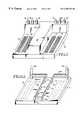
- FIGS. 6A-Care diagrams of respective ink flow pathways for ink from respective ink reservoirs
- FIG. 7is a diagram of a printhead die, partial carrier substrate and partial manifold illustrating ink receipt from three ink sources.
- FIG. 8is a cross-sectional view of a portion of the printhead assembly according to another embodiment of the invention.
- a thermal inkjet printing system 10includes an inkjet printhead assembly 12 , an ink supply assembly 14 , a mounting assembly 16 , a media transport assembly 18 , a housing 20 and an electronic controller 22 .
- the inkjet printhead assembly 12is formed according to an embodiment of this invention, and includes one or more printheads having a plurality of inkjet nozzles 17 which eject ink onto a media sheet M.
- the printhead assembly 12receives ink from the ink supply assembly 14 .
- the ink supply assembly 14includes a reservoir 15 for storing the ink. Ink is supplied to the printhead assembly 12 in either a recirculating or a closed end delivery system.
- the ink supply assembly 14 and inkjet printhead assembly 12are housed together in an inkjet pen or cartridge.
- the ink supply assembly 14is separate from the inkjet printhead assembly 12 and feeds ink to the printhead assembly through an interface connection, such as a supply tube.
- the ink supplymay be removed, replaced and/or refilled.
- the penmay be disassembled and the internal reservoir removed. A new, filled reservoir then is placed within the pen, and the pen reassembled for re-use.
- the prior reservoirmay be refilled and reinstalled in the pen or filled in place without removal from the pen (and in some embodiments without even disassembling the pen).
- the separate reservoir and/or the local reservoirmay be removed, replaced and/or refilled.
- the inkjet printhead assembly 12is mounted relative to the housing 20 to define a print zone 19 adjacent to the printhead nozzles 17 in an area which is to receive the media sheet M.
- the media sheet Mis moved into the print zone 19 by the media transport assembly 18 .
- the mounting assembly 16positions the printhead assembly 12 relative to the media transport assembly 18 .
- the mounting assembly 16includes a carriage for moving the printhead assembly 12 relative to a media transport path to scan the printhead assembly 12 relative to the media sheet.
- the mounting assembly 16includes a mechanism for indexing movement of the printhead assembly 12 relative to the media transport path.
- the mounting assembly 16fixes the inkjet printhead assembly 12 at a prescribed position along the media transport path.
- the electronic controller 22receives documents, files or other data 21 to be printed from a host system, such as a computer. Typically, a print job is sent to the inkjet printing system 10 along an electronic, infrared, optical or other information transfer path. The print job includes data and one or more commands or command parameters. The electronic controller 22 includes memory for temporarily storing the data. The electronic controller 22 provides timing control for firing respective inkjet nozzles 17 to define a pattern of ejected ink drops which form characters, symbols or other graphics on the media sheet M. The pattern is determined by the print job data and print job commands or command parameters.
- ink within the surrounding nozzle chamber 46is ejected through the nozzle opening 48 onto a media sheet M.
- the electronic controller 22selects which firing resistors 50 are active at a given time by activating corresponding drive signals to heat the corresponding firing resistors 50 .
- logic circuits and drive circuits forming a portion of the controller 22are mounted to the substrate 32 of the printhead assembly 12 . In an alternative embodiment logic circuitry and drive circuitry are located off the printhead assembly 12 .
- the printhead assembly 12includes a plurality of inkjet printhead dies 30 mounted to a first face 31 of a carrier substrate 32 .
- An ink manifold 33is mounted to a second face 35 of the carrier substrate 32 . Illustrated is a wide array inkjet printhead assembly.
- the ink manifold 33includes one or more inlets 37 and one or more corresponding outlets 39 coupled to corresponding ink reservoirs 15 .
- each pair of one inlet 37 and one outlet 39is coupled to a corresponding reservoir 15 .
- the manifold 33includes a channel for flowing ink received from a given reservoir 15 at one inlet 37 through the channel to the outlet 39 and back to the reservoir. Ink also flows from the manifold 33 through the carrier substrate 32 and into refill slots of the printhead dies 30 .
- the manifold 33does not include outlets 39 for cycling ink back to the reservoir. In such case, ink flows into the manifold 33 from the ink reservoir 15 and exits through the carrier substrate 32 to the printhead dies' refill slots.
- the one or more reservoirs 15are part of the ink supply assembly 14 .
- the printhead assembly 12may span a nominal page width or a shorter or longer width, and may be of the scanning type, indexing type or non-moving type.
- the reservoirsare replaceable or refillable reservoirs.
- the reservoirsare coupled to corresponding external reservoirs which supply the local reservoirs.
- the reservoirsare non-refillable.
- the printhead dies 30are aligned in one or more rows 38 on a first surface 31 of the carrier substrate 32 .
- the rowsare staggered so that the spacings are offset.
- Each one of the printhead dies 30includes a plurality of rows 42 of inkjet printing elements 44 , also referred to as nozzles.
- the respective rows of printing elements 44also are aligned.
- Each printhead die 30includes an array of printing elements 44 .
- each printing element 44includes a nozzle chamber 46 having a nozzle opening 48 .
- a firing resistor 50is located within the nozzle chamber 46 .
- Wiring lines 52electrically couple the firing resistor 50 to a drive signal and ground.
- Each printhead die 30also includes a refill channel 54 . Ink flows from the internal reservoir 15 into inlet 37 of the ink manifold 33 along path 59 , through a manifold channel 60 , out a manifold 33 feed opening 61 , through the corresponding through-opening 63 of the carrier substrate 32 , and into the refill channels 54 of the printhead dies 30 . Ink flows through each printhead refill channel 54 into the a plurality of printhead nozzle chambers 46 via respective ink feed channels 56 .
- one or more of the printhead dies 30is a fully integrated thermal inkjet printhead formed by a silicon die 62 , a thin film structure 64 and an orifice layer 66 . Glass or a stable polymer are used in place of the silicon in alternative embodiments.
- the thin film structure 64is formed by one or more passivation or insulation layers of silicon dioxide, silicon carbide, silicon nitride, tantalum, poly silicon glass; or another suitable material.
- the thin film structurealso includes a conductive layer for defining the firing resistor 50 and the wiring lines 52 .
- the conductive layeris formed by aluminum, gold, tantalum, tantalum-aluminum or other metal or metal alloy.
- the carrier substrate 32is made of silicon or a multilayered ceramic material.
- the carrier substrate 32serves to carry the plurality of printhead dies 30 , provide electrical interconnection among the printhead dies 30 , and provide electrical interconnection between the printhead dies 30 and the electronic controller 22 (see FIG. 1 ).
- One of the advantages of the carrier substrateis that a thin film layer of metal or metal pads (e.g., gold) are accurately sized and placed on the substrate. Such metalization allows for precise positioning and alignment of the printhead dies 30 .
- the carrier substrateincludes through-channels or through-openings 63 for passing ink from the ink manifold 33 to the printhead dies 30 .
- the substrate 32is formed of similar material as used in forming hybrid multichip modules, although other materials may be used.
- the ceramic substratepreferably has a coefficient of thermal expansion matching that of silicon, is able to receive solder and interconnect layers, and is able to receive mounting of integrated circuits.
- the substrate 32includes a top layer 70 upon which the printhead dies 30 are mounted, a bottom layer 72 and several intermediary layers 74 .
- the intermediary layersprovide electrical interconnection and include one or more signal distribution layers 78 , a power plane layer 80 , and a ground plane layer 82 .
- the signal distribution layers 78include circuit patterns. Conductive vias pierce the layers 78 , 80 , 82 forming electrical interconnects between circuits.
- circuit patternsare formed in layers of unfired tape (referred to as a green sheet) using a screen printing process.
- the green sheetis made of ceramic particles in a polymer binder.
- Aluminaalthough not having the same coefficient of thermal expansion as silicon, may be used for the particles, although other oxides, nitrides, carbides, or other ceramics various glass/ceramic blends also may also be used.
- Each green sheet layerreceives conductor lines and other metallization patterns as needed to define the signal distribution planes 78 , the power plane 80 , and the ground plane 82 .
- Such lines and patternsare formed with a refractory metal, such as tungsten, by screen printing on the corresponding green sheet layer. Electrical interconnects are made from one layer to the next through via holes punched out from the green sheet and filled in with tungsten.
- the through openings 63 within the substrate 32are formed by punching holes and cavities of desired size and shape through the alumina tape. Although only one through-opening 63 is shown for a given printhead die 30 , there may be additional through-openings to the same printhead die to provide ink of respective differing colors.
- the layersare stacked in the desired configuration and laminated under pressure.
- the substratethen is shaped to a desired outer dimension size allotting for shrinkage during a subsequent processing.
- the ceramic and metallization materialsare cosintered at approximately 1600° C., creating a monolithic carrier substrate structure having a three dimensional wiring system.
- Metal partssuch as I/O pins and seal rings are attached with a molten brazing process, such as a silver-copper eutectic brazing or a pure silver brazing. Exposed metal and metallization surfaces then are covered in a plating process, such as a nickel plating process and a finish plating, such as a gold plating with nickel undercoating. The finish plating serves to hermetically seal the ceramic substrate.
- the top layer 70typically is metallized in preparation for surface mounting the printhead dies 30 .
- the bottom layer 72is adapted to receive drive and control circuits and connectors 75 (see FIG. 5 ).
- the ink manifold 33includes a housing 82 , one or more inlets 37 and one or more outlets 39 .
- Each one or more pairs of an inlet 37 and an outlet 39are coupled to a corresponding reservoir.
- one pair of an inlet 37 and an outlet 39is coupled to a reservoir of cyan ink.
- Another pair of an inlet 37 and an outlet 39is coupled to a reservoir of magenta ink.
- Yet another pair of an inlet 37 and an outlet 39is coupled to a reservoir of yellow ink.
- the number of pairs 37 / 39 , reservoirs 15 and colors of inkmay vary. Illustrated is a manifold for a printhead assembly supporting three colors of ink.
- a fourth color ink(e.g., black) also is supported by including additional pathways and an inlet/outlet pair.
- FIGS. 6A-Cshow respective pathways through the ink manifold 33 for corresponding inlet/outlet pairs. Note that the housing is removed and that the other pathways and inlet/outlet pairs are omitted for illustrative clarity.
- FIG. 6Ashows the pathway for one inlet/outlet pair 37 a / 39 a.
- FIG. 6Bshows the pathway for one inlet/outlet pair 37 b / 39 b.
- FIG. 6Cshows the pathway for one inlet/outlet pair 37 c / 39 c.
- inkis received at inlet 37 a, then travels through a channel 60 a.
- the channel 60 aextends from the inlet 37 a to the outlet 39 a.
- each fill opening 61 afluidly couples to a corresponding through-opening 63 (see FIGS. 3 and 7) in the carrier substrate 32 .
- there is a fill opening 61 a for each printhead die 30which is to print ink from the source reservoir feeding the inlet 37 a. Ink is cycled through the channel 60 a from inlet 37 a to outlet 39 a. Along the way, some ink flows out the manifold 33 through the carrier substrate 32 to the printhead dies 30 .
- inkis received at inlet 37 b, then travels through a channel 60 b.
- the channel 60 bextends from the inlet 37 b to the outlet 39 b.
- Each fill opening 61 bfluidly couples to a corresponding through-opening 63 (see FIGS. 3 and 7) in the carrier substrate 32 .
- there is a fill opening 61 b for each printhead die 30which is to print ink from the source reservoir feeding the inlet 37 b.
- Inkis cycled through the channel 60 b from inlet 37 b to outlet 39 b. Along the way, some ink flows out the manifold 33 through the carrier substrate 32 to the printhead dies 30 .
- inkis received at inlet 37 c, then travels through a channel 60 c.
- the channel 60 cextends from the inlet 37 c to the outlet 39 c.
- Each fill opening 61 bfluidly couples to a corresponding through-opening 63 (see FIGS. 3 and 7) in the carrier substrate 32 .
- there is a fill opening 61 c for each printhead die 30which is to print ink from the source reservoir feeding the inlet 37 c.
- Inkis cycled through the channel 60 c from inlet 37 c to outlet 39 c. Along the way, some ink flows out the manifold 33 through the carrier substrate 32 to the printhead dies 30 .
- each printhead die 30includes respective sets of nozzles for printing ink of a corresponding color.
- Such printhead diesinclude three ink refill slots 54 a-c, one for receiving ink from each of the respective manifold channels 60 a-c.
- the three channels 60 a-ccarry ink of respective colors (e.g., cyan, magenta, and yellow).
- FIG. 7shows a given printhead die 30 with the three ink refill slots 54 a-c receiving ink through the carrier substrate 32 from the ink manifold channels 60 a-c.
- the ink manifold channels 60 a-care formed by a molding process in one embodiment and attached to the carrier substrate 32 using an ink-resistant epoxy or other adhesive. In another embodiment the channels 60 a-c are machined to the desired shape and assembled, then attached to the carrier substrate 32 using an ink-resistant epoxy or adhesive. In still another embodiment the channels 60 a-c are assembled and compressed using gaskets.
- the manifold 33including the channels 60 are formed from plastic, metal, ceramic or another suitable material.
- a tube or other external communication channelconnects a portion of channel 60 serving one row to another portion of channel 60 serving another row.
- Fluid interconnectsare achieved as described in the related application of Beerling et al. (Ser. No. 08/959,376, “Scalable Wide-Array Inkjet Printhead and Method for Fabricating Same,” filed on Oct. 28, 1997), cross-referenced above and included herein by reference.
- the printhead dies 30are carried by the manifold 33 , rather than the substrate 32 .
- An electrical signal carrier 86embodies the substrate 32 or electrically connects the dies 30 the substrate 32 .
- the signal carrier 86is in the form of a mask which is mounted to the manifold 33 on the same side of the manifold 33 as the printhead dies 30 .
- There are openings in the signal carrier 86which allow the printhead dies 30 to be mounted in contact with the manifold 33 .
- the dies 30are electrically coupled to the signal carrier 86 by interconnection tabs 88 , 90 and a wire bond 92 , although other electrical bonding, wire bonding or TAB interconnection processes may be used.
- One advantage of the inventionis that a manifold formed separate from the carrier substrate and mounted to the carrier substrate is that new printhead designs may be more rapidly prototyped and tested.
- a multilayer ceramic carrier substratefewer layers are needed thereby reducing the complexity of the carrier substrate and reducing the cost of fabricating the carrier substrate. Some of such cost reduction is offset by the fabrication of the manifold.
- significant savingsaccrue.
- Other advantagesinclude added stability to the carrier substrate by excluding large internal cavities and a more rigid printhead assembly.
Landscapes
- Engineering & Computer Science (AREA)
- Manufacturing & Machinery (AREA)
- Physics & Mathematics (AREA)
- Optics & Photonics (AREA)
- Particle Formation And Scattering Control In Inkjet Printers (AREA)
Abstract
Description
Claims (28)
Priority Applications (5)
| Application Number | Priority Date | Filing Date | Title |
|---|---|---|---|
| US09/216,601US6250738B1 (en) | 1997-10-28 | 1998-12-17 | Inkjet printing apparatus with ink manifold |
| US09/648,565US6428145B1 (en) | 1998-12-17 | 2000-08-25 | Wide-array inkjet printhead assembly with internal electrical routing system |
| US09/648,564US6464333B1 (en) | 1998-12-17 | 2000-08-25 | Inkjet printhead assembly with hybrid carrier for printhead dies |
| US10/229,453US6705705B2 (en) | 1998-12-17 | 2002-08-28 | Substrate for fluid ejection devices |
| US10/681,547US6997540B2 (en) | 1998-12-17 | 2003-10-08 | Substrate for fluid ejection devices |
Applications Claiming Priority (3)
| Application Number | Priority Date | Filing Date | Title |
|---|---|---|---|
| US08/959,376US6123410A (en) | 1997-10-28 | 1997-10-28 | Scalable wide-array inkjet printhead and method for fabricating same |
| US09/216,601US6250738B1 (en) | 1997-10-28 | 1998-12-17 | Inkjet printing apparatus with ink manifold |
| US09/216,606US6322206B1 (en) | 1997-10-28 | 1998-12-17 | Multilayered platform for multiple printhead dies |
Related Parent Applications (2)
| Application Number | Title | Priority Date | Filing Date |
|---|---|---|---|
| US08/959,376Continuation-In-PartUS6123410A (en) | 1997-10-28 | 1997-10-28 | Scalable wide-array inkjet printhead and method for fabricating same |
| US09/216,606Continuation-In-PartUS6322206B1 (en) | 1997-10-28 | 1998-12-17 | Multilayered platform for multiple printhead dies |
Related Child Applications (3)
| Application Number | Title | Priority Date | Filing Date |
|---|---|---|---|
| US09/216,606Continuation-In-PartUS6322206B1 (en) | 1997-10-28 | 1998-12-17 | Multilayered platform for multiple printhead dies |
| US09/648,564Continuation-In-PartUS6464333B1 (en) | 1998-12-17 | 2000-08-25 | Inkjet printhead assembly with hybrid carrier for printhead dies |
| US09/648,565Continuation-In-PartUS6428145B1 (en) | 1998-12-17 | 2000-08-25 | Wide-array inkjet printhead assembly with internal electrical routing system |
Publications (1)
| Publication Number | Publication Date |
|---|---|
| US6250738B1true US6250738B1 (en) | 2001-06-26 |
Family
ID=46203517
Family Applications (1)
| Application Number | Title | Priority Date | Filing Date |
|---|---|---|---|
| US09/216,601Expired - LifetimeUS6250738B1 (en) | 1997-10-28 | 1998-12-17 | Inkjet printing apparatus with ink manifold |
Country Status (1)
| Country | Link |
|---|---|
| US (1) | US6250738B1 (en) |
Cited By (97)
| Publication number | Priority date | Publication date | Assignee | Title |
|---|---|---|---|---|
| EP1186417A3 (en)* | 2000-08-25 | 2002-07-17 | Hewlett-Packard Company | Wide-array inkjet printhead assembly with internal electrical routing system |
| US6435652B1 (en)* | 2000-12-11 | 2002-08-20 | Xerox Corporation | Methods and apparatus for full width printing using a sparsely populated printhead |
| US6464333B1 (en)* | 1998-12-17 | 2002-10-15 | Hewlett-Packard Company | Inkjet printhead assembly with hybrid carrier for printhead dies |
| US6471335B1 (en)* | 2001-08-06 | 2002-10-29 | Creo Inc. | Method for mutual spatial registration of inkjet cartridges |
| US6511165B1 (en) | 2001-10-11 | 2003-01-28 | Hewlett-Packard Company | Manifold intake for coupling ink supplies with foam/filter fluidic interconnects to tube-based printing systems |
| US6523940B2 (en)* | 2000-08-25 | 2003-02-25 | Hewlett-Packard Company | Carrier for fluid ejection device |
| US6530647B2 (en) | 2000-11-01 | 2003-03-11 | Toshiba Tec Kabushiki Kaisha | Color ink-jet head |
| WO2003020523A1 (en)* | 2001-09-04 | 2003-03-13 | Silverbrook Research Pty. Ltd. | Ink supply arrangement for a printer |
| US20030103114A1 (en)* | 2001-11-30 | 2003-06-05 | Brother Kogyo Kabushiki Kaisha. | Inkjet head for inkjet printing apparatus |
| US20030107621A1 (en)* | 2000-06-30 | 2003-06-12 | Kia Silverbrook | Printhead structure |
| US20030112295A1 (en)* | 2001-12-18 | 2003-06-19 | Daquino Lawrence J. | Pulse jet print head assembly having multiple reservoirs and methods for use in the manufacture of biopolymeric arrays |
| US20030113730A1 (en)* | 2001-12-18 | 2003-06-19 | Daquino Lawrence J. | Pulse jet print head having multiple printhead dies and methods for use in the manufacture of biopolymeric arrays |
| WO2003059626A3 (en)* | 2002-01-02 | 2003-10-09 | Jemtex Ink Jet Printing Ltd | Ink jet printing apparatus |
| US20030202052A1 (en)* | 2002-04-30 | 2003-10-30 | Manish Giri | Layer with discontinuity over fluid slot |
| US6644781B2 (en)* | 2001-03-27 | 2003-11-11 | Silverbrook Research Pty Ltd | Printhead assembly having printhead modules in a channel |
| EP1386740A1 (en)* | 2002-07-31 | 2004-02-04 | Hewlett-Packard Company | Slotted substrate |
| US6705705B2 (en)* | 1998-12-17 | 2004-03-16 | Hewlett-Packard Development Company, L.P. | Substrate for fluid ejection devices |
| US20040080587A1 (en)* | 2000-05-23 | 2004-04-29 | Silverbrook Research Pty Ltd | Ink distribution assembly |
| US20040085393A1 (en)* | 2002-10-30 | 2004-05-06 | Scheffelin Joseph E. | Fluid delivery for printhead assembly |
| US20040085394A1 (en)* | 2002-10-30 | 2004-05-06 | Michael Martin | Fluid interconnect for printhead assembly |
| US20040085397A1 (en)* | 2002-10-30 | 2004-05-06 | Scheffelin Joseph E. | Flush process for carrier of printhead assembly |
| US6733112B2 (en) | 2000-08-25 | 2004-05-11 | Hewlett-Packard Development Company | Carrier for printhead assembly including fluid manifold and isolation wells for electrical components |
| US20040095420A1 (en)* | 2000-07-25 | 2004-05-20 | Yuichiro Ikemoto | Printer and printer head |
| US20040095425A1 (en)* | 2000-03-06 | 2004-05-20 | Silverbrook Research Pty Ltd | Laminated support structure for silicon printhead modules |
| US20040113998A1 (en)* | 2000-05-23 | 2004-06-17 | Silverbrook Research Pty Ltd | Printhead chassis assembly |
| US20040174408A1 (en)* | 2003-03-06 | 2004-09-09 | Hewlett-Packard Development Company, L.P. | Printer servicing system and method |
| US6789878B2 (en) | 1997-10-28 | 2004-09-14 | Hewlett-Packard Development Company, L.P. | Fluid manifold for printhead assembly |
| US6796731B2 (en)* | 2000-05-23 | 2004-09-28 | Silverbrook Research Pty Ltd | Laminated ink distribution assembly for a printer |
| US20040218003A1 (en)* | 2003-04-30 | 2004-11-04 | Hewlett-Packard Development Company, L.P. | Printing apparatus and method |
| US20040239732A1 (en)* | 2001-11-26 | 2004-12-02 | Kia Silverbrook | Ink supply arrangement for a printer |
| US20050030359A1 (en)* | 2003-08-06 | 2005-02-10 | Mark Haines | Filter for printhead assembly |
| US20050030358A1 (en)* | 2003-08-06 | 2005-02-10 | Mark Haines | Filter for printhead assembly |
| US20050041063A1 (en)* | 1998-10-16 | 2005-02-24 | Kia Silverbrook | Pagewidth inkjet printhead incorporating an array of nozzle arrangements |
| US20050157123A1 (en)* | 2004-01-21 | 2005-07-21 | Silverbrook Research Pty Ltd | Inkjet printer cartridge with controlled refill |
| US20050157126A1 (en)* | 2004-01-21 | 2005-07-21 | Silverbrook Research Pty Ltd | Pagewidth inkjet printer cartridge with a refill port |
| US20050157112A1 (en)* | 2004-01-21 | 2005-07-21 | Silverbrook Research Pty Ltd | Inkjet printer cradle with shaped recess for receiving a printer cartridge |
| US20050157013A1 (en)* | 2004-01-21 | 2005-07-21 | Silverbrook Research Pty Ltd | Cradle unit having pivotal electrical contacts for electrically engaging with a pagewidth printhead cartridge |
| US20050157100A1 (en)* | 2004-01-21 | 2005-07-21 | Silverbrook Research Pty Ltd | Inkjet printer cartridge refill dispenser system with variably positioned outlets |
| US20050157053A1 (en)* | 2004-01-21 | 2005-07-21 | Silverbrook Research Pty Ltd | Method for facilitating maintenance of an inkjet printer having a pagewidth printhead |
| US20050185018A1 (en)* | 2001-03-27 | 2005-08-25 | Silverbrook Research Pty Ltd | Ink jet module |
| US20060000090A1 (en)* | 2004-06-30 | 2006-01-05 | Smoot Mary C | Die attach methods and apparatus for micro-fluid ejection device |
| US20060001703A1 (en)* | 2004-06-30 | 2006-01-05 | Bertelsen Craig M | Die attach methods and apparatus for micro-fluid ejection device |
| US20060007276A1 (en)* | 2000-05-23 | 2006-01-12 | Silverbrook Research Pty Ltd | Ink distribution structure for a printhead |
| US20060061619A1 (en)* | 2004-09-22 | 2006-03-23 | Gast Paul D | Imaging device and method |
| US20060066673A1 (en)* | 2000-02-09 | 2006-03-30 | Silverbrook Research Pty Ltd | Printhead assembly with a mounting channel having a silicon core |
| US20060103707A1 (en)* | 2004-11-15 | 2006-05-18 | Hewlett-Packard Development Company, Lp | Media print system |
| US20070070362A1 (en)* | 1998-11-09 | 2007-03-29 | Silverbrook Research Pty Ltd | Printhead assembly with a controller for predetermined pattern printing |
| US20070200895A1 (en)* | 2006-02-03 | 2007-08-30 | Moscato Anthony V | Apparatus for printing using a plurality of printing cartridges |
| USD557332S1 (en)* | 2002-09-12 | 2007-12-11 | Seiko Epson Corporation | Ink jet liquid injector |
| US20080036817A1 (en)* | 2001-03-27 | 2008-02-14 | Silverbrook Research Pty Ltd | Printhead assembly with a flexible extrusion |
| US20080043071A1 (en)* | 2006-06-28 | 2008-02-21 | Johnnie Coffey | Printhead Assembly Having Vertically Overlapping Ink Flow Channels |
| US20080043072A1 (en)* | 2006-06-29 | 2008-02-21 | Michael Clark Campbell | Printhead Assembly Having Ink Flow Channels to Accommodate Offset Chips |
| US20080068419A1 (en)* | 2000-05-24 | 2008-03-20 | Silverbrook Research Pty Ltd | Printing assembly with micro-electromechanical nozzle arrangements and a convergent ink distribution assembly |
| US20080151003A1 (en)* | 1999-06-30 | 2008-06-26 | Silverbrook Research Pty Ltd | Inkjet Printhead Assembly Incorporating A Sealing Shim With Aperture Sets |
| US20080259125A1 (en)* | 2007-04-23 | 2008-10-23 | Haluzak Charles C | Microfluidic device and a fluid ejection device incorporating the same |
| US20080259123A1 (en)* | 2000-05-24 | 2008-10-23 | Silverbrook Research Pty Ltd | Printhead assembly with an ink cassette having an air filter |
| US20090058942A1 (en)* | 2000-03-09 | 2009-03-05 | Silverbrook Research Pty Ltd | Method of aligning two or more printhead modules mounted to a support member in a printer |
| US20090141086A1 (en)* | 2002-11-23 | 2009-06-04 | Silverbrook Research Pty Ltd | Inkjet Printhead Unit Cell With Heater Element |
| US20090213172A1 (en)* | 1998-11-09 | 2009-08-27 | Silverbrook Research Pty Ltd | Inkjet Printer With A Protective Print Media Input Tray |
| US20090267994A1 (en)* | 2005-04-18 | 2009-10-29 | Canon Kabushiki Kaisha | Liquid discharge head, ink jet recording head and ink jet recording apparatus |
| US20090295878A1 (en)* | 2008-05-28 | 2009-12-03 | Hanchak Michael S | Jetting module installation and alignment apparatus |
| US20090322830A1 (en)* | 2008-06-30 | 2009-12-31 | Fujifilm Dimatix, Inc. | Ink delivery |
| US20100177135A1 (en)* | 2004-01-21 | 2010-07-15 | Silverbrook Research Pty Ltd | Inkjet printer assembly with driven mechanisms and transmission assembly for driving driven mechanisms |
| US20100214381A1 (en)* | 2004-01-21 | 2010-08-26 | Silverbrook Research Pty Ltd | Plunge action refill dispenser for inkjet printer cartridge |
| US20100225700A1 (en)* | 2004-01-21 | 2010-09-09 | Silverbrook Research Pty Ltd | Print cartridge with printhead ic and multi-functional rotor element |
| US20100231642A1 (en)* | 2004-01-21 | 2010-09-16 | Silverbrook Research Pty Ltd. | Printer cartridge incorporating printhead integrated circuit |
| US20100231665A1 (en)* | 2004-01-21 | 2010-09-16 | Silverbrook Research Pty Ltd | Cartridge unit for printer |
| US20100245503A1 (en)* | 2004-01-21 | 2010-09-30 | Silverbrook Research Pty Ltd | Inkjet printer with releasable print cartridge |
| US20100265288A1 (en)* | 2004-01-21 | 2010-10-21 | Silverbrook Research Pty Ltd | Printer cradle for ink cartridge |
| US20100277538A1 (en)* | 2000-05-24 | 2010-11-04 | Silverbrook Research Pty Ltd | Print engine assembly with twin bearing moldings received within chassis |
| US20110050814A1 (en)* | 2009-08-27 | 2011-03-03 | Ricoh Company, Ltd., | Image forming apparatus with a structure for preventing bubbles from entering recording head or remaining in a fluid supply channel |
| US20110057989A1 (en)* | 2000-05-24 | 2011-03-10 | Silverbrook Research Pty Ltd | Inkjet printing device having rotating platen |
| US7984974B2 (en) | 2002-11-23 | 2011-07-26 | Silverbrook Research Pty Ltd | Printhead integrated circuit with low voltage thermal actuators |
| US8047633B2 (en) | 1998-10-16 | 2011-11-01 | Silverbrook Research Pty Ltd | Control of a nozzle of an inkjet printhead |
| WO2012074514A1 (en)* | 2010-11-30 | 2012-06-07 | Hewlett-Packard Development Company, L.P. | Manifold assembly for fluid-ejection device |
| US20120162322A1 (en)* | 2010-12-22 | 2012-06-28 | Seiko Epson Corporation | Liquid supplying mechanism and liquid ejecting apparatus |
| US8702205B2 (en) | 2000-05-23 | 2014-04-22 | Zamtec Ltd | Printhead assembly incorporating ink distribution assembly |
| WO2014133516A1 (en)* | 2013-02-28 | 2014-09-04 | Hewlett-Packard Development Company, L.P. | Molded fluid flow structure |
| WO2014133561A1 (en)* | 2013-02-28 | 2014-09-04 | Hewlett-Packard Development Company, L.P. | Molding a fluid flow structure |
| WO2014133633A1 (en)* | 2013-02-28 | 2014-09-04 | Hewlett-Packard Development Company, L.P. | Molded printhead |
| US8894191B2 (en) | 2011-08-12 | 2014-11-25 | R. R. Donnelley & Sons, Inc. | Apparatus and method for disposing inkjet cartridges in a carrier |
| US9126445B1 (en) | 2014-04-14 | 2015-09-08 | Xerox Corporation | Modular print bar assembly for an inkjet printer |
| US20150258787A1 (en)* | 2014-03-17 | 2015-09-17 | Seiko Epson Corporation | Liquid ejecting head and liquid ejecting apparatus |
| US20160009085A1 (en)* | 2013-02-28 | 2016-01-14 | Hewlett-Packard Development Company, L.P. | Transfer molded fluid flow structure |
| US20160016404A1 (en)* | 2013-02-28 | 2016-01-21 | Hewlett-Packard Development Company, L.P. | Printed circuit board fluid ejection apparatus |
| US9446587B2 (en) | 2013-02-28 | 2016-09-20 | Hewlett-Packard Development Company, L.P. | Molded printhead |
| US9539814B2 (en) | 2013-02-28 | 2017-01-10 | Hewlett-Packard Development Company, L.P. | Molded printhead |
| US9656469B2 (en) | 2013-02-28 | 2017-05-23 | Hewlett-Packard Development Company, L.P. | Molded fluid flow structure with saw cut channel |
| US9731509B2 (en) | 2013-02-28 | 2017-08-15 | Hewlett-Packard Development Company, L.P. | Fluid structure with compression molded fluid channel |
| EP3148811A4 (en)* | 2014-05-30 | 2018-01-17 | Hewlett-Packard Development Company, L.P. | Printhead assembly module |
| US10029467B2 (en) | 2013-02-28 | 2018-07-24 | Hewlett-Packard Development Company, L.P. | Molded printhead |
| US20180222226A1 (en)* | 2017-02-06 | 2018-08-09 | Memjet Technology Limited | Printhead having heated shield plate |
| US10272683B2 (en)* | 2014-03-17 | 2019-04-30 | Seiko Epson Corporation | Flow path structure, liquid ejecting head, and liquid ejecting apparatus |
| US10336074B1 (en) | 2018-01-18 | 2019-07-02 | Rf Printing Technologies | Inkjet printhead with hierarchically aligned printhead units |
| US10632752B2 (en) | 2013-02-28 | 2020-04-28 | Hewlett-Packard Development Company, L.P. | Printed circuit board fluid flow structure and method for making a printed circuit board fluid flow structure |
| US20220002149A1 (en)* | 2015-11-05 | 2022-01-06 | Hewlett-Packard Development Company, L.P. | Three-dimensional features formed in molded panel |
| US11292257B2 (en) | 2013-03-20 | 2022-04-05 | Hewlett-Packard Development Company, L.P. | Molded die slivers with exposed front and back surfaces |
Citations (8)
| Publication number | Priority date | Publication date | Assignee | Title |
|---|---|---|---|---|
| US4578687A (en)* | 1984-03-09 | 1986-03-25 | Hewlett Packard Company | Ink jet printhead having hydraulically separated orifices |
| US4620198A (en)* | 1985-11-20 | 1986-10-28 | Xerox Corporation | Multicolor ink jet printhead |
| US4917286A (en) | 1987-05-20 | 1990-04-17 | Hewlett-Packard Company | Bonding method for bumpless beam lead tape |
| US5016023A (en) | 1989-10-06 | 1991-05-14 | Hewlett-Packard Company | Large expandable array thermal ink jet pen and method of manufacturing same |
| US5124717A (en)* | 1990-12-06 | 1992-06-23 | Xerox Corporation | Ink jet printhead having integral filter |
| US5160945A (en)* | 1991-05-10 | 1992-11-03 | Xerox Corporation | Pagewidth thermal ink jet printhead |
| US5473350A (en)* | 1992-08-06 | 1995-12-05 | Scitex Digital Printing, Inc. | System and method for maintaining ink concentration in a system |
| US5500661A (en)* | 1992-07-06 | 1996-03-19 | Canon Kabushiki Kaisha | Ink jet recording method |
- 1998
- 1998-12-17USUS09/216,601patent/US6250738B1/ennot_activeExpired - Lifetime
Patent Citations (8)
| Publication number | Priority date | Publication date | Assignee | Title |
|---|---|---|---|---|
| US4578687A (en)* | 1984-03-09 | 1986-03-25 | Hewlett Packard Company | Ink jet printhead having hydraulically separated orifices |
| US4620198A (en)* | 1985-11-20 | 1986-10-28 | Xerox Corporation | Multicolor ink jet printhead |
| US4917286A (en) | 1987-05-20 | 1990-04-17 | Hewlett-Packard Company | Bonding method for bumpless beam lead tape |
| US5016023A (en) | 1989-10-06 | 1991-05-14 | Hewlett-Packard Company | Large expandable array thermal ink jet pen and method of manufacturing same |
| US5124717A (en)* | 1990-12-06 | 1992-06-23 | Xerox Corporation | Ink jet printhead having integral filter |
| US5160945A (en)* | 1991-05-10 | 1992-11-03 | Xerox Corporation | Pagewidth thermal ink jet printhead |
| US5500661A (en)* | 1992-07-06 | 1996-03-19 | Canon Kabushiki Kaisha | Ink jet recording method |
| US5473350A (en)* | 1992-08-06 | 1995-12-05 | Scitex Digital Printing, Inc. | System and method for maintaining ink concentration in a system |
Non-Patent Citations (6)
| Title |
|---|
| Deshmukh, Brady, Roll, King, Shmulovic, Zolnowski, "Active Atmosphere Solder Self-Alignment and Bonding of Optical Components", The International Journal of Microcircuits and Electronic Packaging, vol. 16, #2, second quarter 1993, pp. 97-107. |
| Imler, Scholz, Cobarruviaz, Nagesh, Chao, Haitz, "Precision Flip-Chip Solder Bump Interconnects for Optical Packaging", IEEE Transactions on Components, Hybrids, and Manfacturing Tech., vol. 15, #6, Dec. 1992, pp. 997-982. |
| Itoh, Sasaki, Uda, Yoneda, Honmou, Fukushima, "Use of AuSn Solder Bumps in Three-dimensional Passive Aligned Packaging of LD/PD Arrays on Si Optical Benches", IEEE Electronic Components and Technology Conference, 1996, pp. 1-7. |
| Kallmayer, Oppermann, Kloeser, Zakel, Reichl, Experimental Results on the Self-Alignment Process Using Au/Sn Metallurgy and on the Growth of the C-Phase During the Reflow, '95 Flip Chip, BGA, TAB & AP Symposium, 1995, pp. 225-237. |
| Linder, Baltes, Gnaedinger, Doering, "Photolithography in Anisotropically Etched Grooves", IEEE 9th Intl. Workshop on MEMS, 1996, pp. 38-43. |
| Ludwig, "Multilayered focal plane structures with self-aligning detector assembly", Infrared Readout Electronics III, SPIE, vol. 2745, 1996, pp. 149-158. |
Cited By (417)
| Publication number | Priority date | Publication date | Assignee | Title |
|---|---|---|---|---|
| US6789878B2 (en) | 1997-10-28 | 2004-09-14 | Hewlett-Packard Development Company, L.P. | Fluid manifold for printhead assembly |
| US8066355B2 (en) | 1998-10-16 | 2011-11-29 | Silverbrook Research Pty Ltd | Compact nozzle assembly of an inkjet printhead |
| US7562963B2 (en) | 1998-10-16 | 2009-07-21 | Silverbrook Research Pty Ltd | Pagewidth inkjet printhead assembly with nozzle arrangements having actuator arms configured to be in thermal balance when in a quiescent state |
| US8057014B2 (en) | 1998-10-16 | 2011-11-15 | Silverbrook Research Pty Ltd | Nozzle assembly for an inkjet printhead |
| US7101020B2 (en)* | 1998-10-16 | 2006-09-05 | Silverbrook Research Pty Ltd | Pagewidth inkjet printhead assembly with data and power supply mounted on ink distribution assembly |
| US8047633B2 (en) | 1998-10-16 | 2011-11-01 | Silverbrook Research Pty Ltd | Control of a nozzle of an inkjet printhead |
| US7396108B2 (en) | 1998-10-16 | 2008-07-08 | Silverbrook Research Pty Ltd | Pagewidth printhead assembly with flexible tab film for supplying power and data to printhead integrated circuits |
| US20050041063A1 (en)* | 1998-10-16 | 2005-02-24 | Kia Silverbrook | Pagewidth inkjet printhead incorporating an array of nozzle arrangements |
| US7004563B2 (en)* | 1998-10-16 | 2006-02-28 | Silverbrook Research Pty Ltd | Pagewidth inkjet printhead incorporating an array of nozzle arrangements |
| US20080211879A1 (en)* | 1998-10-16 | 2008-09-04 | Silverbrook Research Pty Ltd | Pagewidth inkjet printhead assembly with nozzle arrangements having actuator arms configured to be in thermal balance when in a quiescent state |
| US20060268064A1 (en)* | 1998-10-16 | 2006-11-30 | Silverbrook Research Pty Ltd | Pagewidth printhead assembly with flexible tab film for supplying power and data to printhead integrated circuits |
| US8061795B2 (en) | 1998-10-16 | 2011-11-22 | Silverbrook Research Pty Ltd | Nozzle assembly of an inkjet printhead |
| US20060092220A1 (en)* | 1998-10-16 | 2006-05-04 | Silverbrook Research Pty Ltd | Pagewidth inkjet printhead assembly with data and power supply mounted on ink distribution assembly |
| US7950771B2 (en) | 1998-10-16 | 2011-05-31 | Silverbrook Research Pty Ltd | Printhead nozzle arrangement with dual mode thermal actuator |
| US20090256890A1 (en)* | 1998-10-16 | 2009-10-15 | Silverbrook Research Pty Ltd | Printhead Nozzle Arrangement With Dual Mode Thermal Actuator |
| US8087757B2 (en) | 1998-10-16 | 2012-01-03 | Silverbrook Research Pty Ltd | Energy control of a nozzle of an inkjet printhead |
| US8113647B2 (en) | 1998-11-09 | 2012-02-14 | Silverbrook Research Pty Ltd | Inkjet printer with a protective print media input tray |
| US20070070362A1 (en)* | 1998-11-09 | 2007-03-29 | Silverbrook Research Pty Ltd | Printhead assembly with a controller for predetermined pattern printing |
| US20090213172A1 (en)* | 1998-11-09 | 2009-08-27 | Silverbrook Research Pty Ltd | Inkjet Printer With A Protective Print Media Input Tray |
| US7433073B2 (en)* | 1998-11-09 | 2008-10-07 | Silverbrook Research Pty Ltd | Printhead assembly with a controller for predetermined pattern printing |
| US20040100522A1 (en)* | 1998-12-17 | 2004-05-27 | Janis Horvath | Substrate for fluid ejection devices |
| US6705705B2 (en)* | 1998-12-17 | 2004-03-16 | Hewlett-Packard Development Company, L.P. | Substrate for fluid ejection devices |
| US6464333B1 (en)* | 1998-12-17 | 2002-10-15 | Hewlett-Packard Company | Inkjet printhead assembly with hybrid carrier for printhead dies |
| US6997540B2 (en) | 1998-12-17 | 2006-02-14 | Hewlett-Packard Development Company, L.P. | Substrate for fluid ejection devices |
| US9796182B2 (en) | 1999-06-30 | 2017-10-24 | Memjet Technology Limited | Inkjet printhead assembly having modular printhead chip carriers defining convergent ink galleries |
| US8662636B2 (en) | 1999-06-30 | 2014-03-04 | Zamtec Ltd | Inkjet printhead having rows of printhead segments |
| US9085148B2 (en) | 1999-06-30 | 2015-07-21 | Memjet Technology Ltd. | Inkjet printhead assembly |
| US9168755B2 (en) | 1999-06-30 | 2015-10-27 | Memjet Technology Ltd. | Inkjet printhead assembly |
| US7891768B2 (en) | 1999-06-30 | 2011-02-22 | Silverbrook Research Pty Ltd | Printhead assembly with an ink supply arrangement having printhead segment carriers |
| US7922290B2 (en) | 1999-06-30 | 2011-04-12 | Silverbrook Research Pty Ltd | Printhead assembly having printhead integrated circuit carriers arranged end-to-end on ink supply support structure |
| US8905519B2 (en) | 1999-06-30 | 2014-12-09 | Memjet Technology Ltd. | Inkjet printhead assembly comprising printhead modules having converging ink galleries |
| US20090213193A1 (en)* | 1999-06-30 | 2009-08-27 | Silverbrook Research Pty Ltd | Printhead Assembly Having Printhead Integrated Circuit Carriers Arranged End-To-End On Ink Supply Support Structure |
| US20080151003A1 (en)* | 1999-06-30 | 2008-06-26 | Silverbrook Research Pty Ltd | Inkjet Printhead Assembly Incorporating A Sealing Shim With Aperture Sets |
| US9713923B2 (en) | 1999-06-30 | 2017-07-25 | Memjet Technology Limited | Inkjet printhead assembly having printhead chip carriers received in slot |
| US10035347B2 (en) | 1999-06-30 | 2018-07-31 | Memjet Technology Ltd. | Inkjet printhead assembly having printhead chip carriers received in slot |
| US20080273054A1 (en)* | 1999-06-30 | 2008-11-06 | Silverbrook Research Pty Ltd | Printhead assembly having an ink supply arrangement and a plurality of printhead segment carriers |
| US9539819B2 (en) | 1999-06-30 | 2017-01-10 | Mernjet Technology Limited | Inkjet printhead assembly including slotted shield plate |
| US8556386B2 (en) | 1999-06-30 | 2013-10-15 | Zamtec Ltd | Printhead having nested modules |
| US20080297562A1 (en)* | 1999-06-30 | 2008-12-04 | Silverbrook Research Pty Ltd | Printhead assembly with an ink supply arrangement having printhead segment carriers |
| US7771014B2 (en)* | 1999-06-30 | 2010-08-10 | Silverbrook Research Pty Ltd | Printhead assembly having an ink supply arrangement and a plurality of printhead segment carriers |
| US7901042B2 (en) | 1999-06-30 | 2011-03-08 | Silverbrook Research Pty Ltd | Inkjet printhead assembly incorporating a sealing shim with aperture sets |
| US20060066673A1 (en)* | 2000-02-09 | 2006-03-30 | Silverbrook Research Pty Ltd | Printhead assembly with a mounting channel having a silicon core |
| US7334867B2 (en) | 2000-03-06 | 2008-02-26 | Silverbrook Research Pty Ltd | Support beam for printhead modules |
| US20040095425A1 (en)* | 2000-03-06 | 2004-05-20 | Silverbrook Research Pty Ltd | Laminated support structure for silicon printhead modules |
| US20070268334A1 (en)* | 2000-03-06 | 2007-11-22 | Silverbrook Research Pty Ltd | Printhead Assembly With Two-Material Supporting Structure |
| US7950772B2 (en) | 2000-03-06 | 2011-05-31 | Silverbrook Research Pty Ltd. | Printhead assembly having supporting structure of alternating materials |
| US6984021B2 (en)* | 2000-03-06 | 2006-01-10 | Silverbrook Research Pty Ltd | Laminated support structure for silicon printhead modules |
| US7270396B2 (en) | 2000-03-06 | 2007-09-18 | Silverbrook Research Pty Ltd | Composite pagewidth-printhead supporting structure |
| US20090295860A1 (en)* | 2000-03-06 | 2009-12-03 | Silverbrook Research Pty Ltd | Printhead assembly having supporting structure of alternating materials |
| US6869167B2 (en)* | 2000-03-06 | 2005-03-22 | Silverbrook Research Pty Ltd | Supporting structure for a pagewidth printhead |
| US7581815B2 (en) | 2000-03-06 | 2009-09-01 | Silverbrook Research Pty Ltd | Printhead assembly with two-material supporting structure |
| US20040130592A1 (en)* | 2000-03-06 | 2004-07-08 | Silverbrook Research Pty Ltd | Supporting structure for a pagewidth printhead |
| US20080111860A1 (en)* | 2000-03-06 | 2008-05-15 | Silverbrook Research Pty Ltd | Laminated Pagewidth Printhead Thermal Support Assembly |
| US20050219319A1 (en)* | 2000-03-06 | 2005-10-06 | Silverbrook Research Pty Ltd | Support beam for printhead modules |
| US20050128278A1 (en)* | 2000-03-06 | 2005-06-16 | Kia Silverbrook | Composite pagewidth-printhead supporting structure |
| US7556346B2 (en) | 2000-03-06 | 2009-07-07 | Silverbrook Research Pty Ltd | Laminated pagewidth printhead thermal support assembly |
| US7455390B2 (en)* | 2000-03-09 | 2008-11-25 | Silverbrook Research Pty Ltd | Printhead assembly with a mounting channel having a silicon core |
| US7942499B2 (en) | 2000-03-09 | 2011-05-17 | Silverbrook Research Pty Ltd | Method of aligning two or more printhead modules mounted to a support member in a printer |
| US7901038B2 (en) | 2000-03-09 | 2011-03-08 | Silverbrook Research Pty Ltd | Printhead assembly incorporating heat aligning printhead modules |
| US20090058942A1 (en)* | 2000-03-09 | 2009-03-05 | Silverbrook Research Pty Ltd | Method of aligning two or more printhead modules mounted to a support member in a printer |
| US20040113998A1 (en)* | 2000-05-23 | 2004-06-17 | Silverbrook Research Pty Ltd | Printhead chassis assembly |
| US7467859B2 (en) | 2000-05-23 | 2008-12-23 | Silverbrook Research Pty Ltd | Pagewidth printhead assembly with ink distribution arrangement |
| US8702205B2 (en) | 2000-05-23 | 2014-04-22 | Zamtec Ltd | Printhead assembly incorporating ink distribution assembly |
| US8696096B2 (en) | 2000-05-23 | 2014-04-15 | Zamtec Ltd | Laminated ink supply structure mounted in ink distribution arrangement of an inkjet printer |
| US20050162468A1 (en)* | 2000-05-23 | 2005-07-28 | Kia Silverbrook | Printhead assembly |
| US7425053B2 (en) | 2000-05-23 | 2008-09-16 | Silverbrook Research Pty Ltd | Printhead assembly with a laminated ink distribution assembly |
| US20100134559A1 (en)* | 2000-05-23 | 2010-06-03 | Silverbrook Research Pty Ltd | Printhead assembly incorporating laminated ink distribution stack |
| US7740338B2 (en) | 2000-05-23 | 2010-06-22 | Silverbrook Research Pty Ltd | Printhead assembly having a pressurised air supply |
| US20070195115A1 (en)* | 2000-05-23 | 2007-08-23 | Silverbrook Research Pty Ltd | Printhead assembly with printheads within a laminated stack which, in turn is within an ink distribution structure |
| US20050140757A1 (en)* | 2000-05-23 | 2005-06-30 | Kia Silverbrook | Printhead assembly with stacked ink distribution sheets |
| US7658467B2 (en)* | 2000-05-23 | 2010-02-09 | Silverbrook Research Pty Ltd | Printhead assembly laminated ink distribution stack |
| US7748833B2 (en) | 2000-05-23 | 2010-07-06 | Silverbrook Research Pty Ltd | Ink distribution structure with a laminated ink supply stack for an inkjet printer |
| US20050219307A1 (en)* | 2000-05-23 | 2005-10-06 | Silverbrook Research Pty Ltd | Printer having a rotary platen assembly for supporting print media |
| US20050225611A1 (en)* | 2000-05-23 | 2005-10-13 | Silverbrook Research Pty Ltd. | Printer with a self-cleaning inkjet printhead assembly |
| US20050110844A1 (en)* | 2000-05-23 | 2005-05-26 | Kia Silverbrook | Multi-function printhead platen |
| US20080158296A1 (en)* | 2000-05-23 | 2008-07-03 | Silverbrook Research Pty Ltd | Printhead assembly laminated ink distribution stack |
| US20100271426A1 (en)* | 2000-05-23 | 2010-10-28 | Silverbrook Research Pty Ltd | Laminated ink supply structure mounted in ink distribution arrangement of an inkjet printer |
| US20080284829A1 (en)* | 2000-05-23 | 2008-11-20 | Silverbrook Research Pty Ltd | Printhead assembly having a pressurised air supply |
| US9254655B2 (en) | 2000-05-23 | 2016-02-09 | Memjet Technology Ltd. | Inkjet printer having laminated stack for receiving ink from ink distribution molding |
| US6984080B2 (en)* | 2000-05-23 | 2006-01-10 | Silverbrook Research Pty Ltd | Laminated distribution structure |
| US20060007276A1 (en)* | 2000-05-23 | 2006-01-12 | Silverbrook Research Pty Ltd | Ink distribution structure for a printhead |
| US20060008307A1 (en)* | 2000-05-23 | 2006-01-12 | Silverbrook Research Pty Ltd | Print engine assembly with an elongate converging ink distribution assembly |
| US20060013631A1 (en)* | 2000-05-23 | 2006-01-19 | Silverbrook Research Pty Ltd | Inkjet printing assembly with multi-purpose platen assembly |
| US6988840B2 (en)* | 2000-05-23 | 2006-01-24 | Silverbrook Research Pty Ltd | Printhead chassis assembly |
| US6994419B2 (en) | 2000-05-23 | 2006-02-07 | Silverbrook Research Pty Ltd | Multi-function printhead platen |
| US20050007421A1 (en)* | 2000-05-23 | 2005-01-13 | Kia Silverbrook | Ink and air distribution within a printer assembly |
| US6997626B2 (en)* | 2000-05-23 | 2006-02-14 | Silverbrook Research Pty Ltd | Ink and air distribution within a printer assembly |
| US7980658B2 (en) | 2000-05-23 | 2011-07-19 | Silverbrook Research Pty Ltd | Rotatable platen |
| US6997625B2 (en)* | 2000-05-23 | 2006-02-14 | Silverbrook Research Pty Ltd | Ink distribution assembly |
| US6796731B2 (en)* | 2000-05-23 | 2004-09-28 | Silverbrook Research Pty Ltd | Laminated ink distribution assembly for a printer |
| US7931358B2 (en) | 2000-05-23 | 2011-04-26 | Silverbrook Research Pty Ltd | Pagewidth printhead assembly with top-fed ink ducts |
| US9028048B2 (en) | 2000-05-23 | 2015-05-12 | Memjet Technology Ltd. | Printhead assembly incorporating ink distribution assembly |
| US7213989B2 (en) | 2000-05-23 | 2007-05-08 | Silverbrook Research Pty Ltd | Ink distribution structure for a printhead |
| US20080106579A1 (en)* | 2000-05-23 | 2008-05-08 | Silverbrook Research Pty Ltd | Ink Distribution Structure With A Laminated Ink Supply Stack For An Inkjet Printer |
| US7284817B2 (en) | 2000-05-23 | 2007-10-23 | Silverbrook Research Pty Ltd | Printer with a self-cleaning inkjet printhead assembly |
| US7044577B2 (en) | 2000-05-23 | 2006-05-16 | Silverbrook Research Pty Ltd | Printer having a rotary platen assembly for supporting print media |
| US20090033713A1 (en)* | 2000-05-23 | 2009-02-05 | Silverbrook Research Pty Ltd | Method of operating inkjet printer |
| US20090033712A1 (en)* | 2000-05-23 | 2009-02-05 | Silverbrook Research Pty Ltd | Rotatable platen |
| US7364377B2 (en) | 2000-05-23 | 2008-04-29 | Silverbrook Research Pty Ltd | Print engine assembly with an elongate converging ink distribution assembly |
| US6652078B2 (en) | 2000-05-23 | 2003-11-25 | Silverbrook Research Pty Ltd | Ink supply arrangement for a printer |
| US20090058973A1 (en)* | 2000-05-23 | 2009-03-05 | Silverbrook Research Pty Ltd | Printing apparatus and method |
| US7083258B2 (en) | 2000-05-23 | 2006-08-01 | Silverbrook Research Pty Ltd | Printhead assembly |
| US20090066765A1 (en)* | 2000-05-23 | 2009-03-12 | Silverbrook Research Pty Ltd | Pagewidth Printhead Assembly With Top-Fed Ink Ducts |
| US7114868B2 (en) | 2000-05-23 | 2006-10-03 | Silverbrook Research Pty Ltd | Inkjet printing assembly with multi-purpose platen assembly |
| US20040080587A1 (en)* | 2000-05-23 | 2004-04-29 | Silverbrook Research Pty Ltd | Ink distribution assembly |
| US7328994B2 (en) | 2000-05-23 | 2008-02-12 | Silverbrook Research Pty Ltd | Print engine assembly with slotted chassis |
| US7325986B2 (en)* | 2000-05-23 | 2008-02-05 | Silverbrook Research Pty Ltd | Printhead assembly with stacked ink distribution sheets |
| US7841710B2 (en) | 2000-05-23 | 2010-11-30 | Silverbrook Research Pty Ltd | Printhead assembly with a pressurized air supply for an inkjet printer |
| US20070013739A1 (en)* | 2000-05-23 | 2007-01-18 | Silverbrook Research Pty Ltd | Print engine assembly with slotted chassis |
| US20080018697A1 (en)* | 2000-05-23 | 2008-01-24 | Silverbrook Research Pty Ltd | Printhead assembly with air cleaning arrangement |
| US7192125B2 (en) | 2000-05-23 | 2007-03-20 | Silverbrook Research Pty Ltd | Ink jet printer that incorporates an ink distribution assembly |
| US7824021B2 (en) | 2000-05-23 | 2010-11-02 | Silverbrook Research Pty Ltd | Printhead assembly with printheads within a laminated stack which, in turn is within an ink distribution structure |
| US8075112B2 (en) | 2000-05-23 | 2011-12-13 | Silverbrook Research Pty Ltd | Printhead assembly with air cleaning arrangement |
| US20100277538A1 (en)* | 2000-05-24 | 2010-11-04 | Silverbrook Research Pty Ltd | Print engine assembly with twin bearing moldings received within chassis |
| US20080068419A1 (en)* | 2000-05-24 | 2008-03-20 | Silverbrook Research Pty Ltd | Printing assembly with micro-electromechanical nozzle arrangements and a convergent ink distribution assembly |
| US20090027454A1 (en)* | 2000-05-24 | 2009-01-29 | Silverbrook Research Pty Ltd | Print engine assembly with chassis and printed circuit board |
| US7455391B2 (en)* | 2000-05-24 | 2008-11-25 | Silverbrook Research Pty Ltd | Printing assembly with micro-electromechanical nozzle arrangements and a convergent ink distribution assembly |
| US20080259123A1 (en)* | 2000-05-24 | 2008-10-23 | Silverbrook Research Pty Ltd | Printhead assembly with an ink cassette having an air filter |
| US20110057989A1 (en)* | 2000-05-24 | 2011-03-10 | Silverbrook Research Pty Ltd | Inkjet printing device having rotating platen |
| US7744201B2 (en)* | 2000-05-24 | 2010-06-29 | Silverbrook Research Pty Ltd | Printhead assembly with an ink cassette having an air filter |
| US20110063363A1 (en)* | 2000-05-24 | 2011-03-17 | Silverbrook Research Pty Ltd | Inkjet printer having an inkjet printhead and a rotating platen |
| US20110063364A1 (en)* | 2000-05-24 | 2011-03-17 | Silverbrook Research Pty Ltd | Rotating platen |
| US20110063365A1 (en)* | 2000-05-24 | 2011-03-17 | Silverbrook Research Pty Ltd | Method of operating an inkjet printer |
| US8678550B2 (en) | 2000-05-24 | 2014-03-25 | Zamtec Ltd | Printhead assembly with laminated ink distribution stack |
| US7066588B2 (en) | 2000-06-30 | 2006-06-27 | Silverbrook Research Pty Ltd | Print engine assembly |
| US7794066B2 (en)* | 2000-06-30 | 2010-09-14 | Silverbrook Research Pty Ltd | Printhead structure having fluid passages defined in silicon |
| US8366241B2 (en) | 2000-06-30 | 2013-02-05 | Zamtec Ltd | Printhead having capped fluid passages |
| US20050140755A1 (en)* | 2000-06-30 | 2005-06-30 | Kia Silverbrook | Printhead structure having fluid passages defined in silicon |
| US6871937B2 (en)* | 2000-06-30 | 2005-03-29 | Silverbrook Research Pty Ltd | Printhead structure |
| US7237874B2 (en) | 2000-06-30 | 2007-07-03 | Silverbrook Research Pty Ltd | Inkjet printhead with grouped nozzles and a nozzle guard |
| US20070229587A1 (en)* | 2000-06-30 | 2007-10-04 | Silvebrook Research Pty Ltd | Print engine incorporating a print media cutter assembly |
| US20060227171A1 (en)* | 2000-06-30 | 2006-10-12 | Silverbrook Research Pty Ltd | Inkjet printhead with grouped nozzles and a nozzle guard |
| US7753503B2 (en) | 2000-06-30 | 2010-07-13 | Silverbrook Research Pty Ltd | Print engine incorporating a print media cutter assembly |
| US20050162487A1 (en)* | 2000-06-30 | 2005-07-28 | Kia Silverbrook, Tobin Allen King And Garry Raymond Jackson | Print engine assembly |
| US20030107621A1 (en)* | 2000-06-30 | 2003-06-12 | Kia Silverbrook | Printhead structure |
| US6676250B1 (en)* | 2000-06-30 | 2004-01-13 | Silverbrook Research Pty Ltd | Ink supply assembly for a print engine |
| US20040095420A1 (en)* | 2000-07-25 | 2004-05-20 | Yuichiro Ikemoto | Printer and printer head |
| US6793319B2 (en)* | 2000-07-25 | 2004-09-21 | Sony Corporation | Printer and printer head |
| US7240986B2 (en) | 2000-07-25 | 2007-07-10 | Sony Corporation | Printer and printer head |
| US6733112B2 (en) | 2000-08-25 | 2004-05-11 | Hewlett-Packard Development Company | Carrier for printhead assembly including fluid manifold and isolation wells for electrical components |
| US6523940B2 (en)* | 2000-08-25 | 2003-02-25 | Hewlett-Packard Company | Carrier for fluid ejection device |
| EP1186417A3 (en)* | 2000-08-25 | 2002-07-17 | Hewlett-Packard Company | Wide-array inkjet printhead assembly with internal electrical routing system |
| US6530647B2 (en) | 2000-11-01 | 2003-03-11 | Toshiba Tec Kabushiki Kaisha | Color ink-jet head |
| US6435652B1 (en)* | 2000-12-11 | 2002-08-20 | Xerox Corporation | Methods and apparatus for full width printing using a sparsely populated printhead |
| US7448725B2 (en) | 2001-03-27 | 2008-11-11 | Silverbrook Research Pty Ltd | Inkjet printhead assembly that incorporates an ink jet capper |
| US7712867B2 (en)* | 2001-03-27 | 2010-05-11 | Silverbrook Research Pty Ltd | Printhead assembly with a flexible extrusion |
| US20070153061A1 (en)* | 2001-03-27 | 2007-07-05 | Silverbrook Research Pty Ltd. | Inkjet printhead assembly with obliquely oriented printheads |
| US7401891B2 (en) | 2001-03-27 | 2008-07-22 | Silverbrook Research Pty Ltd | Printhead assembly incorporating a capping arrangement |
| US7416277B2 (en) | 2001-03-27 | 2008-08-26 | Silverbrook Research Pty Ltd | Inkjet printhead assembly with obliquely oriented printheads |
| US20050200654A1 (en)* | 2001-03-27 | 2005-09-15 | Silverbrook Research Pty Ltd | Printhead assembly comprising printhead modules arranged in a channel |
| US20080204504A1 (en)* | 2001-03-27 | 2008-08-28 | Silverbrook Research Pty Ltd | Inkjet printhead assembly with capped obliquely oriented printheads |
| US7918533B2 (en) | 2001-03-27 | 2011-04-05 | Silverbrook Research Pty Ltd | Printhead with printhead module locator |
| US6644781B2 (en)* | 2001-03-27 | 2003-11-11 | Silverbrook Research Pty Ltd | Printhead assembly having printhead modules in a channel |
| US7914131B2 (en) | 2001-03-27 | 2011-03-29 | Silverbrook Research Pty Ltd | Inkjet printhead assembly having releasably attached printhead modules |
| US6966628B2 (en)* | 2001-03-27 | 2005-11-22 | Silverbrook Research Pty Ltd | Printhead assembly having printhead modules in channel |
| US20050185018A1 (en)* | 2001-03-27 | 2005-08-25 | Silverbrook Research Pty Ltd | Ink jet module |
| US20060028504A1 (en)* | 2001-03-27 | 2006-02-09 | Silverbrook Research Pty Ltd | Printhead assembly incorporating a capping arrangement |
| US7938505B2 (en) | 2001-03-27 | 2011-05-10 | Silverbrook Research Pty Ltd | Printhead assembly with ink supply via extrusion |
| US20080246824A1 (en)* | 2001-03-27 | 2008-10-09 | Silverbrook Research Pty Ltd | Modular pagewidth printhead assembly having a fluid distribution assembly with elastomeric pads for taking up tolerance |
| US7182430B2 (en)* | 2001-03-27 | 2007-02-27 | Silverbrook Research Pty Ltd | Ink jet module |
| US20040090491A1 (en)* | 2001-03-27 | 2004-05-13 | Kia Silverbrook | Printhead assembly having printhead modules in a channel |
| US7076872B2 (en) | 2001-03-27 | 2006-07-18 | Siverbrook Research Pty Ltd | Method of assembly of a printhead with modules in a channel |
| US7032993B2 (en) | 2001-03-27 | 2006-04-25 | Silverbrook Research Pty Ltd | Printhead assembly comprising printhead modules arranged in a channel |
| US20090021559A1 (en)* | 2001-03-27 | 2009-01-22 | Silverbrook Research Pty Ltd | Printhead with printhead module locator |
| US7775631B2 (en) | 2001-03-27 | 2010-08-17 | Silverbrook Research Pty Ltd | Modular pagewidth printhead assembly having a fluid distribution assembly with elastomeric pads for taking up tolerance |
| US20050012779A1 (en)* | 2001-03-27 | 2005-01-20 | Kia Silverbrook | Method of assembly of a printhead with modules in a channel |
| US20080036817A1 (en)* | 2001-03-27 | 2008-02-14 | Silverbrook Research Pty Ltd | Printhead assembly with a flexible extrusion |
| US7794065B2 (en) | 2001-03-27 | 2010-09-14 | Silverbrook Research Pty Ltd | Inkjet printhead assembly with capped obliquely oriented printheads |
| US20060250442A1 (en)* | 2001-03-27 | 2006-11-09 | Silverbrook Research Pty Ltd | Inkjet printhead assembly that incorporates an ink jet capper |
| US6471335B1 (en)* | 2001-08-06 | 2002-10-29 | Creo Inc. | Method for mutual spatial registration of inkjet cartridges |
| WO2003020523A1 (en)* | 2001-09-04 | 2003-03-13 | Silverbrook Research Pty. Ltd. | Ink supply arrangement for a printer |
| US7178892B2 (en) | 2001-09-04 | 2007-02-20 | Silverbrook Res Pty Ltd | Printhead-to-platen variable spacing mechanism |
| US6918647B2 (en) | 2001-09-04 | 2005-07-19 | Silverbrook Research Pty Ltd | Inkjet printhead assembly having a rotary platen assembly |
| US6511165B1 (en) | 2001-10-11 | 2003-01-28 | Hewlett-Packard Company | Manifold intake for coupling ink supplies with foam/filter fluidic interconnects to tube-based printing systems |
| US20040239732A1 (en)* | 2001-11-26 | 2004-12-02 | Kia Silverbrook | Ink supply arrangement for a printer |
| US20030103114A1 (en)* | 2001-11-30 | 2003-06-05 | Brother Kogyo Kabushiki Kaisha. | Inkjet head for inkjet printing apparatus |
| US6758553B2 (en)* | 2001-11-30 | 2004-07-06 | Brother Kogyo Kabushiki Kaisha | Inkjet head for inkjet printing apparatus |
| US20030112295A1 (en)* | 2001-12-18 | 2003-06-19 | Daquino Lawrence J. | Pulse jet print head assembly having multiple reservoirs and methods for use in the manufacture of biopolymeric arrays |
| US20030113730A1 (en)* | 2001-12-18 | 2003-06-19 | Daquino Lawrence J. | Pulse jet print head having multiple printhead dies and methods for use in the manufacture of biopolymeric arrays |
| US6935727B2 (en)* | 2001-12-18 | 2005-08-30 | Agilent Technologies, Inc. | Pulse jet print head assembly having multiple reservoirs and methods for use in the manufacture of biopolymeric arrays |
| US7128398B2 (en) | 2001-12-18 | 2006-10-31 | Agilent Technologies, Inc. | Pulse jet print head assembly having multiple reservoirs and methods for use in the manufacture of biopolymeric arrays |
| US7182442B2 (en) | 2002-01-02 | 2007-02-27 | Jemtex Ink Jet Printing Ltd. | Ink jet printing apparatus |
| US20050083381A1 (en)* | 2002-01-02 | 2005-04-21 | Yehoshua Sheinman | Ink jet printing apparatus |
| WO2003059626A3 (en)* | 2002-01-02 | 2003-10-09 | Jemtex Ink Jet Printing Ltd | Ink jet printing apparatus |
| US7024768B2 (en)* | 2002-04-30 | 2006-04-11 | Hewlett-Packard Development Company, L.P. | Fluid ejection device having a layer with a discontinuity |
| US20060125885A1 (en)* | 2002-04-30 | 2006-06-15 | Manish Giri | Layer with discontinuity over fluid slot |
| US20030202052A1 (en)* | 2002-04-30 | 2003-10-30 | Manish Giri | Layer with discontinuity over fluid slot |
| US7501070B2 (en) | 2002-07-31 | 2009-03-10 | Hewlett-Packard Development Company, L.P. | Slotted substrate and method of making |
| EP1386740A1 (en)* | 2002-07-31 | 2004-02-04 | Hewlett-Packard Company | Slotted substrate |
| US20040031151A1 (en)* | 2002-07-31 | 2004-02-19 | Shen Buswell | Slotted substrate and method of making |
| US20040021742A1 (en)* | 2002-07-31 | 2004-02-05 | Shen Buswell | Slotted substrate and method of making |
| US6814431B2 (en) | 2002-07-31 | 2004-11-09 | Hewlett-Packard Development Company, L.P. | Slotted substrate and method of making |
| USD557332S1 (en)* | 2002-09-12 | 2007-12-11 | Seiko Epson Corporation | Ink jet liquid injector |
| US6869165B2 (en) | 2002-10-30 | 2005-03-22 | Hewlett-Packard Development Company, L.P. | Fluid interconnect for printhead assembly |
| EP1415812A1 (en)* | 2002-10-30 | 2004-05-06 | Hewlett-Packard Development Company, L.P. | Fluid delivery for printhead assembly |
| US20040085397A1 (en)* | 2002-10-30 | 2004-05-06 | Scheffelin Joseph E. | Flush process for carrier of printhead assembly |
| US20050117001A1 (en)* | 2002-10-30 | 2005-06-02 | Michael Martin | Fluid interconnect for printhead assembly |
| US6799827B2 (en) | 2002-10-30 | 2004-10-05 | Hewlett-Packard Development Company, L.P. | Flush process for carrier of printhead assembly |
| US20040085394A1 (en)* | 2002-10-30 | 2004-05-06 | Michael Martin | Fluid interconnect for printhead assembly |
| US20040085393A1 (en)* | 2002-10-30 | 2004-05-06 | Scheffelin Joseph E. | Fluid delivery for printhead assembly |
| US6942316B2 (en) | 2002-10-30 | 2005-09-13 | Hewlett-Packard Development Company, L.P. | Fluid delivery for printhead assembly |
| US6964473B2 (en) | 2002-10-30 | 2005-11-15 | Hewlett-Packard Development Company, L.P. | Fluid interconnect for printhead assembly |
| US20100149277A1 (en)* | 2002-11-23 | 2010-06-17 | Silverbrook Research Pty Ltd | Ink Ejection Device With Circular Chamber And Concentric Heater Element |
| US8038262B2 (en) | 2002-11-23 | 2011-10-18 | Silverbrook Research Pty Ltd | Inkjet printhead unit cell with heater element |
| US20100277550A1 (en)* | 2002-11-23 | 2010-11-04 | Silverbrook Research Pty Ltd | Printhead having heater and non-heater elements |
| US20090141086A1 (en)* | 2002-11-23 | 2009-06-04 | Silverbrook Research Pty Ltd | Inkjet Printhead Unit Cell With Heater Element |
| US20100110124A1 (en)* | 2002-11-23 | 2010-05-06 | Silverbrook Research Pty Ltd | Method Of Ejection From Nozzles Of Printhead |
| US20100302317A1 (en)* | 2002-11-23 | 2010-12-02 | Silverbrook Research Pty Ltd | Printhead assembly with a plurality of printhead integrated circuits each with a stack of ink distribution layers |
| US20100045747A1 (en)* | 2002-11-23 | 2010-02-25 | Silverbrook Research Pty Ltd | Printhead Having Planar Bubble Nucleating Heaters |
| US20100156991A1 (en)* | 2002-11-23 | 2010-06-24 | Silverbrook Research Pty Ltd | Printhead having layered heater elements and electrodes |
| US20100271440A1 (en)* | 2002-11-23 | 2010-10-28 | Silverbrook Research Pty Ltd | Printhead integrated circuit having low mass heater elements |
| US20090244197A1 (en)* | 2002-11-23 | 2009-10-01 | Silverbrook Research Pty Ltd | Thermal Inkjet Printhead With Double Omega Shaped Heating Element |
| US8721049B2 (en) | 2002-11-23 | 2014-05-13 | Zamtec Ltd | Inkjet printhead having suspended heater element and ink inlet laterally offset from nozzle aperture |
| US7922310B2 (en)* | 2002-11-23 | 2011-04-12 | Silverbrook Research Pty Ltd | Modular printhead assembly |
| US20100165051A1 (en)* | 2002-11-23 | 2010-07-01 | Silverbrook Research Pty Ltd | Printhead having wide heater elements |
| US8322826B2 (en) | 2002-11-23 | 2012-12-04 | Zamtec Limited | Method of ejecting fluid using wide heater element |
| US8303092B2 (en) | 2002-11-23 | 2012-11-06 | Zamtec Limited | Printhead having wide heater elements |
| US8287097B2 (en) | 2002-11-23 | 2012-10-16 | Zamtec Limited | Inkjet printer utilizing low energy titanium nitride heater elements |
| US20100177145A1 (en)* | 2002-11-23 | 2010-07-15 | Silverbrook Research Pty Ltd | Printhead having nozzle plate formed on fluid distributors |
| US8277029B2 (en) | 2002-11-23 | 2012-10-02 | Zamtec Limited | Printhead integrated circuit having low mass heater elements |
| US8118407B2 (en) | 2002-11-23 | 2012-02-21 | Silverbrook Research Pty Ltd | Thermal inkjet printhead having annulus shaped heater elements |
| US8100512B2 (en) | 2002-11-23 | 2012-01-24 | Silverbrook Research Pty Ltd | Printhead having planar bubble nucleating heaters |
| US20100201751A1 (en)* | 2002-11-23 | 2010-08-12 | Silverbrook Research Pty Ltd | Inkjet nozzle assembly with low density suspended heater element |
| US8087751B2 (en) | 2002-11-23 | 2012-01-03 | Silverbrook Research Pty Ltd | Thermal ink jet printhead |
| US20100245485A1 (en)* | 2002-11-23 | 2010-09-30 | Silverbrook Research Pty Ltd | Inkjet printhead with suspended heater element spaced from chamber walls |
| US8075111B2 (en) | 2002-11-23 | 2011-12-13 | Silverbrook Research Pty Ltd | Printhead with ink distribution through aligned apertures |
| US20100245483A1 (en)* | 2002-11-23 | 2010-09-30 | Silverbrook Research Pty Ltd | Unit cell for thermal inkjet printhead |
| US20090153621A1 (en)* | 2002-11-23 | 2009-06-18 | Silverbrook Research Pty Ltd | Modular Printhead Assembly |
| US20100220155A1 (en)* | 2002-11-23 | 2010-09-02 | Silverbrook Research Pty Ltd | Thermal ink jet printhead |
| US8011760B2 (en) | 2002-11-23 | 2011-09-06 | Silverbrook Research Pty Ltd | Inkjet printhead with suspended heater element spaced from chamber walls |
| US20100220142A1 (en)* | 2002-11-23 | 2010-09-02 | Silverbrook Research Pty Ltd | Printhead with ink distribution through aligned apertures |
| US8007075B2 (en) | 2002-11-23 | 2011-08-30 | Silverbrook Research Pty Ltd | Printhead having nozzle plate formed on fluid distributors |
| US7997688B2 (en) | 2002-11-23 | 2011-08-16 | Silverbrook Research Pty Ltd | Unit cell for thermal inkjet printhead |
| US7967417B2 (en) | 2002-11-23 | 2011-06-28 | Silverbrook Research Pty Ltd | Inkjet printhead with symetrical heater and nozzle sharing common plane of symmetry |
| US7988261B2 (en) | 2002-11-23 | 2011-08-02 | Silverbrook Research Pty Ltd | Printhead having layered heater elements and electrodes |
| US7984974B2 (en) | 2002-11-23 | 2011-07-26 | Silverbrook Research Pty Ltd | Printhead integrated circuit with low voltage thermal actuators |
| US20100231649A1 (en)* | 2002-11-23 | 2010-09-16 | Silverbrook Research Pty Ltd | Inkjet printer utilizing low energy titanium nitride heater elements |
| US7980673B2 (en) | 2002-11-23 | 2011-07-19 | Silverbrook Research Pty Ltd | Inkjet nozzle assembly with low density suspended heater element |
| US7971970B2 (en) | 2002-11-23 | 2011-07-05 | Silverbrook Research Pty Ltd | Ink ejection device with circular chamber and concentric heater element |
| US7971974B2 (en) | 2002-11-23 | 2011-07-05 | Silverbrook Research Pty Ltd | Printhead integrated circuit with low loss CMOS connections to heaters |
| US20100245484A1 (en)* | 2002-11-23 | 2010-09-30 | Silverbrook Research Pty Ltd | Thermal inkjet printhead having annulus shaped heater elements |
| US6851787B2 (en) | 2003-03-06 | 2005-02-08 | Hewlett-Packard Development Company, L.P. | Printer servicing system and method |
| US20040174408A1 (en)* | 2003-03-06 | 2004-09-09 | Hewlett-Packard Development Company, L.P. | Printer servicing system and method |
| US6932455B2 (en) | 2003-04-30 | 2005-08-23 | Hewlett-Packard Development Company, L.P. | Printing apparatus and method |
| US20040218003A1 (en)* | 2003-04-30 | 2004-11-04 | Hewlett-Packard Development Company, L.P. | Printing apparatus and method |
| US7614733B2 (en) | 2003-08-06 | 2009-11-10 | Hewlett-Packard Development Company, L.P. | Filter for printhead assembly |
| US20070153070A1 (en)* | 2003-08-06 | 2007-07-05 | Mark Haines | Filter for printhead assembly |
| US7188942B2 (en) | 2003-08-06 | 2007-03-13 | Hewlett-Packard Development Company, L.P. | Filter for printhead assembly |
| US7416295B2 (en) | 2003-08-06 | 2008-08-26 | Hewlett-Packard Development Company, L.P. | Filter for printhead assembly |
| US20050030358A1 (en)* | 2003-08-06 | 2005-02-10 | Mark Haines | Filter for printhead assembly |
| US20050030359A1 (en)* | 2003-08-06 | 2005-02-10 | Mark Haines | Filter for printhead assembly |
| US8100502B2 (en) | 2004-01-21 | 2012-01-24 | Silverbrook Research Pty Ltd | Printer cartridge incorporating printhead integrated circuit |
| US20100182387A1 (en)* | 2004-01-21 | 2010-07-22 | Silverbrook Research Pty Ltd | Reservoir assembly for supplying fluid to printhead |
| US20100134575A1 (en)* | 2004-01-21 | 2010-06-03 | Silverbrook Research Pty Ltd | Refillable ink cartridge with ink bypass channel for refilling |
| US20100283817A1 (en)* | 2004-01-21 | 2010-11-11 | Silverbrook Research Pty Ltd | Printer print engine with cradled cartridge unit |
| US20100134553A1 (en)* | 2004-01-21 | 2010-06-03 | Silverbrook Research Pty Ltd | Printer for nesting with image reader |
| US20100271427A1 (en)* | 2004-01-21 | 2010-10-28 | Silverbrook Research Pty Ltd | Printhead assembly with capillary channels in fluid chambers |
| US20100103220A1 (en)* | 2004-01-21 | 2010-04-29 | Silverbrook Research Pty Ltd | Print Engine For Inkjet Printer |
| US7658483B2 (en) | 2004-01-21 | 2010-02-09 | Silverbrook Research Pty Ltd | Ink storage compartment with bypass fluid path structures |
| US20100165058A1 (en)* | 2004-01-21 | 2010-07-01 | Silverbrook Research Pty Ltd. | Ink Refill Unit Having Discretely Incrementable Variable Storage Volume |
| US7537315B2 (en) | 2004-01-21 | 2009-05-26 | Silverbrook Research Pty Ltd | Cradle unit for a print engine having a maintenance drive assembly |
| US20080291250A1 (en)* | 2004-01-21 | 2008-11-27 | Silverbrook Research Pty Ltd | Printer cartridge for a pagewidth printer having a refill port and a controller board |
| US20050157123A1 (en)* | 2004-01-21 | 2005-07-21 | Silverbrook Research Pty Ltd | Inkjet printer cartridge with controlled refill |
| US20080252700A1 (en)* | 2004-01-21 | 2008-10-16 | Silverbrook Research Pty Ltd | Cartridge For An Inkjet Printer With Refill Docking Interface |
| US7425050B2 (en)* | 2004-01-21 | 2008-09-16 | Silverbrook Research Pty Ltd | Method for facilitating maintenance of an inkjet printer having a pagewidth printhead |
| US20050157126A1 (en)* | 2004-01-21 | 2005-07-21 | Silverbrook Research Pty Ltd | Pagewidth inkjet printer cartridge with a refill port |
| US20080218538A1 (en)* | 2004-01-21 | 2008-09-11 | Silverbrook Research Pty Ltd | Cradle Unit For A Print Engine Having A Maintenance Drive Assembly |
| US20080211888A1 (en)* | 2004-01-21 | 2008-09-04 | Silverbrook Research Pty Ltd | Ink Storage Compartment With Bypass Fluid Path Structures |
| US9044956B2 (en) | 2004-01-21 | 2015-06-02 | Memjet Technology Ltd. | Pagewidth printhead assembly having ink distribution member |
| US20100265288A1 (en)* | 2004-01-21 | 2010-10-21 | Silverbrook Research Pty Ltd | Printer cradle for ink cartridge |
| US7384135B2 (en)* | 2004-01-21 | 2008-06-10 | Silverbrook Research Pty Ltd | Cradle unit having pivotal electrical contacts for electrically engaging with a pagewidth printhead cartridge |
| US20050157112A1 (en)* | 2004-01-21 | 2005-07-21 | Silverbrook Research Pty Ltd | Inkjet printer cradle with shaped recess for receiving a printer cartridge |
| US20050157013A1 (en)* | 2004-01-21 | 2005-07-21 | Silverbrook Research Pty Ltd | Cradle unit having pivotal electrical contacts for electrically engaging with a pagewidth printhead cartridge |
| US20080002007A1 (en)* | 2004-01-21 | 2008-01-03 | Silverbrook Research Pty Ltd | Inkjet Printer With Refill Interface And Variably Positioned Inlets |
| US20100165037A1 (en)* | 2004-01-21 | 2010-07-01 | Silverbrook Research Pty Ltd. | Print cartrdge cradle unit incorporating maintenance assembly |
| US7954920B2 (en) | 2004-01-21 | 2011-06-07 | Silverbrook Research Pty Ltd | Inkjet printer assembly with driven mechanisms and transmission assembly for driving driven mechanisms |
| US20100245503A1 (en)* | 2004-01-21 | 2010-09-30 | Silverbrook Research Pty Ltd | Inkjet printer with releasable print cartridge |
| US7971978B2 (en) | 2004-01-21 | 2011-07-05 | Silverbrook Research Pty Ltd | Refillable ink cartridge with ink bypass channel for refilling |
| US7798622B2 (en) | 2004-01-21 | 2010-09-21 | Silverbrook Research Pty Ltd | Cartridge for an inkjet printer with refill docking interface |
| US20100231665A1 (en)* | 2004-01-21 | 2010-09-16 | Silverbrook Research Pty Ltd | Cartridge unit for printer |
| US20050157100A1 (en)* | 2004-01-21 | 2005-07-21 | Silverbrook Research Pty Ltd | Inkjet printer cartridge refill dispenser system with variably positioned outlets |
| US20100231642A1 (en)* | 2004-01-21 | 2010-09-16 | Silverbrook Research Pty Ltd. | Printer cartridge incorporating printhead integrated circuit |
| US20050157053A1 (en)* | 2004-01-21 | 2005-07-21 | Silverbrook Research Pty Ltd | Method for facilitating maintenance of an inkjet printer having a pagewidth printhead |
| US20100165059A1 (en)* | 2004-01-21 | 2010-07-01 | Silverbrook Research Pty Ltd | Dispenser unit for refilling printing unit |
| US7794070B2 (en) | 2004-01-21 | 2010-09-14 | Silverbrook Research Pty Ltd | Inkjet printer with refill interface and variably positioned inlets |
| US20100225700A1 (en)* | 2004-01-21 | 2010-09-09 | Silverbrook Research Pty Ltd | Print cartridge with printhead ic and multi-functional rotor element |
| US8002393B2 (en) | 2004-01-21 | 2011-08-23 | Silverbrook Research Pty Ltd | Print engine with a refillable printer cartridge and ink refill port |
| US8002394B2 (en) | 2004-01-21 | 2011-08-23 | Silverbrook Research Pty Ltd | Refill unit for fluid container |
| US8007093B2 (en) | 2004-01-21 | 2011-08-30 | Silverbrook Research Pty Ltd | Print engine for inkjet printer |
| US8007083B2 (en) | 2004-01-21 | 2011-08-30 | Silverbrook Research Pty Ltd | Refill unit for incrementally filling fluid container |
| US20100225714A1 (en)* | 2004-01-21 | 2010-09-09 | Silverbrook Research Pty Ltd. | Refill unit having fluid storage actuators |
| US8672450B2 (en)* | 2004-01-21 | 2014-03-18 | Zamtec Ltd | Printhead assembly having electrical connector for transmitting power and data |
| US20100220126A1 (en)* | 2004-01-21 | 2010-09-02 | Silverbrook Research Pty Ltd | Vertical form factor printer |
| US8025381B2 (en) | 2004-01-21 | 2011-09-27 | Silverbrook Research Pty Ltd | Priming system for pagewidth print cartridge |
| US20100214381A1 (en)* | 2004-01-21 | 2010-08-26 | Silverbrook Research Pty Ltd | Plunge action refill dispenser for inkjet printer cartridge |
| US8042922B2 (en) | 2004-01-21 | 2011-10-25 | Silverbrook Research Pty Ltd | Dispenser unit for refilling printing unit |
| US8047639B2 (en) | 2004-01-21 | 2011-11-01 | Silverbrook Research Pty Ltd | Refill unit for incremental millilitre fluid refill |
| US7293861B2 (en)* | 2004-01-21 | 2007-11-13 | Silverbrook Research Pty Ltd | Inkjet printer cartridge refill dispenser system with variably positioned outlets |
| US20100277556A1 (en)* | 2004-01-21 | 2010-11-04 | Silverbrook Research Pty Ltd | Print engine with ink storage modules incorporating collapsible bags |
| US7258432B2 (en)* | 2004-01-21 | 2007-08-21 | Silverbrook Research Pty Ltd | Inkjet printer cartridge with controlled refill |
| US20100214383A1 (en)* | 2004-01-21 | 2010-08-26 | Silverbrook Research Pty Ltd | Cartridge for printer having fluid flow arrangement |
| US8075110B2 (en) | 2004-01-21 | 2011-12-13 | Silverbrook Research Pty Ltd | Refill unit for an ink storage compartment connected to a printhead through an outlet valve |
| US20100207999A1 (en)* | 2004-01-21 | 2010-08-19 | Silverbrook Research Pty Ltd | Pagewidth printhead assembly with ink and data distribution |
| US8500259B2 (en) | 2004-01-21 | 2013-08-06 | Zamtec Ltd | Cartridge for printer having fluid flow arrangement |
| US8079683B2 (en) | 2004-01-21 | 2011-12-20 | Silverbrook Research Pty Ltd | Inkjet printer cradle with shaped recess for receiving a printer cartridge |
| US8079700B2 (en) | 2004-01-21 | 2011-12-20 | Silverbrook Research Pty Ltd | Printer for nesting with image reader |
| US8485651B2 (en) | 2004-01-21 | 2013-07-16 | Zamtec Ltd | Print cartrdge cradle unit incorporating maintenance assembly |
| US20100201740A1 (en)* | 2004-01-21 | 2010-08-12 | Silverbrook Research Pty Ltd | Printhead cradle having electromagnetic control of capper |
| US8439497B2 (en) | 2004-01-21 | 2013-05-14 | Zamtec Ltd | Image processing apparatus with nested printer and scanner |
| US20100128094A1 (en)* | 2004-01-21 | 2010-05-27 | Silverbrook Research Pty Ltd | Print Engine With A Refillable Printer Cartridge And Ink Refill Port |
| US8434858B2 (en) | 2004-01-21 | 2013-05-07 | Zamtec Ltd | Cartridge unit for printer |
| US8398216B2 (en) | 2004-01-21 | 2013-03-19 | Zamtec Ltd | Reservoir assembly for supplying fluid to printhead |
| US8366236B2 (en) | 2004-01-21 | 2013-02-05 | Zamtec Ltd | Print cartridge with printhead IC and multi-functional rotor element |
| US8348386B2 (en) | 2004-01-21 | 2013-01-08 | Zamtec Ltd | Pagewidth printhead assembly with ink and data distribution |
| US8292406B2 (en) | 2004-01-21 | 2012-10-23 | Zamtec Limited | Inkjet printer with releasable print cartridge |
| US20100177135A1 (en)* | 2004-01-21 | 2010-07-15 | Silverbrook Research Pty Ltd | Inkjet printer assembly with driven mechanisms and transmission assembly for driving driven mechanisms |
| US8220900B2 (en) | 2004-01-21 | 2012-07-17 | Zamtec Limited | Printhead cradle having electromagnetic control of capper |
| US8235502B2 (en) | 2004-01-21 | 2012-08-07 | Zamtec Limited | Printer print engine with cradled cartridge unit |
| US8251501B2 (en) | 2004-01-21 | 2012-08-28 | Zamtec Limited | Inkjet print engine having printer cartridge incorporating maintenance assembly and cradle unit incorporating maintenance drive assembly |
| US20060000090A1 (en)* | 2004-06-30 | 2006-01-05 | Smoot Mary C | Die attach methods and apparatus for micro-fluid ejection device |
| US7311386B2 (en) | 2004-06-30 | 2007-12-25 | Lexmark Interntional, Inc. | Die attach methods and apparatus for micro-fluid ejection device |
| US7043838B2 (en) | 2004-06-30 | 2006-05-16 | Lexmark International, Inc. | Process for manufacturing a micro-fluid ejection device |
| US20060001703A1 (en)* | 2004-06-30 | 2006-01-05 | Bertelsen Craig M | Die attach methods and apparatus for micro-fluid ejection device |
| US7311376B2 (en) | 2004-09-22 | 2007-12-25 | Hewlett-Packard Development Company, L.P. | Imaging device and method |
| US20060061619A1 (en)* | 2004-09-22 | 2006-03-23 | Gast Paul D | Imaging device and method |
| US20060103707A1 (en)* | 2004-11-15 | 2006-05-18 | Hewlett-Packard Development Company, Lp | Media print system |
| US7654635B2 (en) | 2004-11-15 | 2010-02-02 | Hewlett-Packard Development Company, L.P. | Media print system |
| US8177330B2 (en) | 2005-04-18 | 2012-05-15 | Canon Kabushiki Kaisha | Liquid discharge head, ink jet recording head and ink jet recording apparatus |
| US20090267994A1 (en)* | 2005-04-18 | 2009-10-29 | Canon Kabushiki Kaisha | Liquid discharge head, ink jet recording head and ink jet recording apparatus |
| US7771010B2 (en) | 2006-02-03 | 2010-08-10 | Rr Donnelley | Apparatus for printing using a plurality of printing cartridges |
| US20070200895A1 (en)* | 2006-02-03 | 2007-08-30 | Moscato Anthony V | Apparatus for printing using a plurality of printing cartridges |
| US7540594B2 (en)* | 2006-06-28 | 2009-06-02 | Lexmark International, Inc. | Printhead assembly having vertically overlapping ink flow channels |
| US20080043071A1 (en)* | 2006-06-28 | 2008-02-21 | Johnnie Coffey | Printhead Assembly Having Vertically Overlapping Ink Flow Channels |
| US7549736B2 (en)* | 2006-06-29 | 2009-06-23 | Lexmark International, Inc. | Printhead assembly having ink flow channels to accommodate offset chips |
| WO2008005258A3 (en)* | 2006-06-29 | 2008-09-12 | Lexmark Int Inc | Printhead assembly having ink flow channels to accommodate offset chips |
| US20080043072A1 (en)* | 2006-06-29 | 2008-02-21 | Michael Clark Campbell | Printhead Assembly Having Ink Flow Channels to Accommodate Offset Chips |
| US7828417B2 (en) | 2007-04-23 | 2010-11-09 | Hewlett-Packard Development Company, L.P. | Microfluidic device and a fluid ejection device incorporating the same |
| US8007078B2 (en) | 2007-04-23 | 2011-08-30 | Hewlett-Packard Development Company, L.P. | Microfluidic device and a fluid ejection device incorporating the same |
| US20110025782A1 (en)* | 2007-04-23 | 2011-02-03 | Haluzak Charles C | Microfluidic device and a fluid ejection device incorporating the same |
| US20080259125A1 (en)* | 2007-04-23 | 2008-10-23 | Haluzak Charles C | Microfluidic device and a fluid ejection device incorporating the same |
| US20090295878A1 (en)* | 2008-05-28 | 2009-12-03 | Hanchak Michael S | Jetting module installation and alignment apparatus |
| US7819501B2 (en)* | 2008-05-28 | 2010-10-26 | Eastman Kodak Company | Jetting module installation and alignment apparatus |
| CN102123870A (en)* | 2008-06-30 | 2011-07-13 | 富士胶卷迪马蒂克斯股份有限公司 | Ink delivery |
| US8807716B2 (en) | 2008-06-30 | 2014-08-19 | Fujifilm Dimatix, Inc. | Ink delivery |
| WO2010002558A1 (en)* | 2008-06-30 | 2010-01-07 | Fujifilm Dimatix, Inc. | Ink delivery |
| US20090322830A1 (en)* | 2008-06-30 | 2009-12-31 | Fujifilm Dimatix, Inc. | Ink delivery |
| US8465125B2 (en)* | 2009-08-27 | 2013-06-18 | Ricoh Company, Ltd. | Image forming apparatus with a structure for preventing bubbles from entering recording head or remaining in a fluid supply channel |
| US20110050814A1 (en)* | 2009-08-27 | 2011-03-03 | Ricoh Company, Ltd., | Image forming apparatus with a structure for preventing bubbles from entering recording head or remaining in a fluid supply channel |
| US8733896B2 (en) | 2010-11-30 | 2014-05-27 | Hewlett-Packard Development Company, L.P. | Manifold assembly for fluid-ejection device |
| WO2012074514A1 (en)* | 2010-11-30 | 2012-06-07 | Hewlett-Packard Development Company, L.P. | Manifold assembly for fluid-ejection device |
| CN102529396A (en)* | 2010-12-22 | 2012-07-04 | 精工爱普生株式会社 | Liquid supplying mechanism and liquid ejecting apparatus |
| US20120162322A1 (en)* | 2010-12-22 | 2012-06-28 | Seiko Epson Corporation | Liquid supplying mechanism and liquid ejecting apparatus |
| US8567916B2 (en)* | 2010-12-22 | 2013-10-29 | Seiko Epson Corporation | Liquid supplying mechanism and liquid ejecting apparatus |
| CN102529396B (en)* | 2010-12-22 | 2016-01-06 | 精工爱普生株式会社 | Liquid feed mechanism and liquid injection apparatus |
| US8894191B2 (en) | 2011-08-12 | 2014-11-25 | R. R. Donnelley & Sons, Inc. | Apparatus and method for disposing inkjet cartridges in a carrier |
| US9539814B2 (en) | 2013-02-28 | 2017-01-10 | Hewlett-Packard Development Company, L.P. | Molded printhead |
| WO2014133516A1 (en)* | 2013-02-28 | 2014-09-04 | Hewlett-Packard Development Company, L.P. | Molded fluid flow structure |
| CN105121167A (en)* | 2013-02-28 | 2015-12-02 | 惠普发展公司,有限责任合伙企业 | Molded printhead |
| CN105121171A (en)* | 2013-02-28 | 2015-12-02 | 惠普发展公司,有限责任合伙企业 | Molded print bar |
| CN105142912A (en)* | 2013-02-28 | 2015-12-09 | 惠普发展公司,有限责任合伙企业 | Molded fluid flow structure with saw cut channel |
| US11541659B2 (en) | 2013-02-28 | 2023-01-03 | Hewlett-Packard Development Company, L.P. | Molded printhead |
| US20160009085A1 (en)* | 2013-02-28 | 2016-01-14 | Hewlett-Packard Development Company, L.P. | Transfer molded fluid flow structure |
| US20160016404A1 (en)* | 2013-02-28 | 2016-01-21 | Hewlett-Packard Development Company, L.P. | Printed circuit board fluid ejection apparatus |
| US11426900B2 (en) | 2013-02-28 | 2022-08-30 | Hewlett-Packard Development Company, L.P. | Molding a fluid flow structure |
| US11130339B2 (en) | 2013-02-28 | 2021-09-28 | Hewlett-Packard Development Company, L.P. | Molded fluid flow structure |
| US9446587B2 (en) | 2013-02-28 | 2016-09-20 | Hewlett-Packard Development Company, L.P. | Molded printhead |
| US9517626B2 (en)* | 2013-02-28 | 2016-12-13 | Hewlett-Packard Development Company, L.P. | Printed circuit board fluid ejection apparatus |
| WO2014133577A1 (en)* | 2013-02-28 | 2014-09-04 | Hewlett-Packard Development Company, L.P. | Transfer molded fluid flow structure |
| WO2014133590A1 (en)* | 2013-02-28 | 2014-09-04 | Hewlett-Packard Development Company, L.P. | Molded printhead |
| US20170072693A1 (en)* | 2013-02-28 | 2017-03-16 | Hewlett-Packard Development Company, L.P. | Printed circuit board fluid ejection apparatus |
| US9656469B2 (en) | 2013-02-28 | 2017-05-23 | Hewlett-Packard Development Company, L.P. | Molded fluid flow structure with saw cut channel |
| US9707753B2 (en) | 2013-02-28 | 2017-07-18 | Hewlett-Packard Development Company, L.P. | Printhead die |
| WO2014133633A1 (en)* | 2013-02-28 | 2014-09-04 | Hewlett-Packard Development Company, L.P. | Molded printhead |
| US9731509B2 (en) | 2013-02-28 | 2017-08-15 | Hewlett-Packard Development Company, L.P. | Fluid structure with compression molded fluid channel |
| US9751319B2 (en) | 2013-02-28 | 2017-09-05 | Hewlett-Packard Development Company, L.P. | Printing fluid cartridge |
| RU2633873C2 (en)* | 2013-02-28 | 2017-10-18 | Хьюлетт-Паккард Дивелопмент Компани, Л.П. | Moulded hydrodynamic structure |
| WO2014133561A1 (en)* | 2013-02-28 | 2014-09-04 | Hewlett-Packard Development Company, L.P. | Molding a fluid flow structure |
| US9844946B2 (en) | 2013-02-28 | 2017-12-19 | Hewlett-Packard Development Company, L.P. | Molded printhead |
| TWI609796B (en)* | 2013-02-28 | 2018-01-01 | 惠普發展公司有限責任合夥企業 | Molded printhead |
| US10994539B2 (en) | 2013-02-28 | 2021-05-04 | Hewlett-Packard Development Company, L.P. | Fluid flow structure forming method |
| US9902162B2 (en)* | 2013-02-28 | 2018-02-27 | Hewlett-Packard Development Company, L.P. | Molded print bar |
| US9919525B2 (en)* | 2013-02-28 | 2018-03-20 | Hewlett-Packard Development Company, L.P. | Printed circuit board fluid ejection apparatus |
| US9944080B2 (en) | 2013-02-28 | 2018-04-17 | Hewlett-Packard Development Company, L.P. | Molded fluid flow structure |
| CN108058485A (en)* | 2013-02-28 | 2018-05-22 | 惠普发展公司,有限责任合伙企业 | The fluid flow structure of molding |
| US10994541B2 (en) | 2013-02-28 | 2021-05-04 | Hewlett-Packard Development Company, L.P. | Molded fluid flow structure with saw cut channel |
| US10029467B2 (en) | 2013-02-28 | 2018-07-24 | Hewlett-Packard Development Company, L.P. | Molded printhead |
| CN105121166A (en)* | 2013-02-28 | 2015-12-02 | 惠普发展公司,有限责任合伙企业 | Transfer molded fluid flow structure |
| US10933640B2 (en) | 2013-02-28 | 2021-03-02 | Hewlett-Packard Development Company, L.P. | Fluid dispenser |
| US10081188B2 (en) | 2013-02-28 | 2018-09-25 | Hewlett-Packard Development Company, L.P. | Molded fluid flow structure with saw cut channel |
| US10160213B2 (en) | 2013-02-28 | 2018-12-25 | Hewlett-Packard Development Company, L.P. | Molded fluid flow structure |
| US10166776B2 (en) | 2013-02-28 | 2019-01-01 | Hewlett-Packard Development Company, L.P. | Molded fluid flow structure |
| US10189265B2 (en) | 2013-02-28 | 2019-01-29 | Hewlett-Packard Development Company, L.P. | Printing fluid cartridge |
| US10195851B2 (en) | 2013-02-28 | 2019-02-05 | Hewlett-Packard Development Company, L.P. | Printhead die |
| US10836169B2 (en) | 2013-02-28 | 2020-11-17 | Hewlett-Packard Development Company, L.P. | Molded printhead |
| US10821729B2 (en)* | 2013-02-28 | 2020-11-03 | Hewlett-Packard Development Company, L.P. | Transfer molded fluid flow structure |
| US10300701B2 (en) | 2013-02-28 | 2019-05-28 | Hewlett-Packard Development Company, L.P. | Printed circuit board fluid ejection apparatus |
| US10632752B2 (en) | 2013-02-28 | 2020-04-28 | Hewlett-Packard Development Company, L.P. | Printed circuit board fluid flow structure and method for making a printed circuit board fluid flow structure |
| US10421279B2 (en) | 2013-02-28 | 2019-09-24 | Hewlett-Packard Development Company, L.P. | Molded printhead |
| CN108058485B (en)* | 2013-02-28 | 2019-10-22 | 惠普发展公司,有限责任合伙企业 | The fluid flow structure of molding |
| US10464324B2 (en) | 2013-02-28 | 2019-11-05 | Hewlett-Packard Development Company, L.P. | Molded fluid flow structure |
| US10603916B2 (en) | 2013-02-28 | 2020-03-31 | Hewlett-Packard Development Company, L.P. | Method of making a fluid structure having compression molded fluid channel |
| US11292257B2 (en) | 2013-03-20 | 2022-04-05 | Hewlett-Packard Development Company, L.P. | Molded die slivers with exposed front and back surfaces |
| US10272683B2 (en)* | 2014-03-17 | 2019-04-30 | Seiko Epson Corporation | Flow path structure, liquid ejecting head, and liquid ejecting apparatus |
| US11235575B2 (en) | 2014-03-17 | 2022-02-01 | Seiko Epson Corporation | Flow path structure, liquid ejecting head, and liquid ejecting apparatus |
| US10717277B2 (en) | 2014-03-17 | 2020-07-21 | Seiko Epson Corporation | Flow path structure, liquid ejecting head, and liquid ejecting apparatus |
| US20150258787A1 (en)* | 2014-03-17 | 2015-09-17 | Seiko Epson Corporation | Liquid ejecting head and liquid ejecting apparatus |
| US10549533B2 (en) | 2014-03-17 | 2020-02-04 | Seiko Epson Corporation | Flow path structure, liquid ejecting head, and liquid ejecting apparatus |
| US9427965B2 (en)* | 2014-03-17 | 2016-08-30 | Seiko Epson Corporation | Liquid ejecting head and liquid ejecting apparatus |
| US9126445B1 (en) | 2014-04-14 | 2015-09-08 | Xerox Corporation | Modular print bar assembly for an inkjet printer |
| EP3148811A4 (en)* | 2014-05-30 | 2018-01-17 | Hewlett-Packard Development Company, L.P. | Printhead assembly module |
| US9987845B2 (en) | 2014-05-30 | 2018-06-05 | Hewlett-Packard Development Company, L.P. | Printhead assembly module |
| US10569543B2 (en) | 2014-05-30 | 2020-02-25 | Hewlett-Packard Development Company, L.P. | Printhead assembly module |
| US20220002149A1 (en)* | 2015-11-05 | 2022-01-06 | Hewlett-Packard Development Company, L.P. | Three-dimensional features formed in molded panel |
| US11807523B2 (en)* | 2015-11-05 | 2023-11-07 | Hewlett-Packard Development Company, L.P. | Three-dimensional features formed in molded panel |
| US20180222226A1 (en)* | 2017-02-06 | 2018-08-09 | Memjet Technology Limited | Printhead having heated shield plate |
| US10239316B2 (en)* | 2017-02-06 | 2019-03-26 | Memjet Technology Limited | Printhead having heated shield plate |
| US10336074B1 (en) | 2018-01-18 | 2019-07-02 | Rf Printing Technologies | Inkjet printhead with hierarchically aligned printhead units |
Similar Documents
| Publication | Publication Date | Title |
|---|---|---|
| US6250738B1 (en) | Inkjet printing apparatus with ink manifold | |
| US6322206B1 (en) | Multilayered platform for multiple printhead dies | |
| US6543880B1 (en) | Inkjet printhead assembly having planarized mounting layer for printhead dies | |
| US6341845B1 (en) | Electrical connection for wide-array inkjet printhead assembly with hybrid carrier for printhead dies | |
| US6789878B2 (en) | Fluid manifold for printhead assembly | |
| US6557976B2 (en) | Electrical circuit for wide-array inkjet printhead assembly | |
| US20030007034A1 (en) | Substrate for fluid ejection devices | |
| US6869165B2 (en) | Fluid interconnect for printhead assembly | |
| US6428145B1 (en) | Wide-array inkjet printhead assembly with internal electrical routing system | |
| KR20020097155A (en) | Droplet deposition apparatus | |
| US6431683B1 (en) | Hybrid carrier for wide-array inkjet printhead assembly | |
| US6575559B2 (en) | Joining of different materials of carrier for fluid ejection devices | |
| US6464333B1 (en) | Inkjet printhead assembly with hybrid carrier for printhead dies | |
| US6942316B2 (en) | Fluid delivery for printhead assembly | |
| US6880246B2 (en) | Method of forming substrate with fluid passage supports | |
| US6733112B2 (en) | Carrier for printhead assembly including fluid manifold and isolation wells for electrical components | |
| US6679581B2 (en) | Surface deformation of carrier for printhead dies |
Legal Events
| Date | Code | Title | Description |
|---|---|---|---|
| AS | Assignment | Owner name:HEWLETT-PACKARD COMPANY, CALIFORNIA Free format text:ASSIGNMENT OF ASSIGNORS INTEREST;ASSIGNORS:WALLER, DAVID J.;BEERLING, TIMOTHY E.;BOYD, MELISSA E.;AND OTHERS;REEL/FRAME:009797/0818 Effective date:19981217 | |
| STCF | Information on status: patent grant | Free format text:PATENTED CASE | |
| FEPP | Fee payment procedure | Free format text:PAYOR NUMBER ASSIGNED (ORIGINAL EVENT CODE: ASPN); ENTITY STATUS OF PATENT OWNER: LARGE ENTITY | |
| FPAY | Fee payment | Year of fee payment:4 | |
| FPAY | Fee payment | Year of fee payment:8 | |
| AS | Assignment | Owner name:HEWLETT-PACKARD DEVELOPMENT COMPANY, L.P., TEXAS Free format text:ASSIGNMENT OF ASSIGNORS INTEREST;ASSIGNOR:HEWLETT-PACKARD COMPANY;REEL/FRAME:026945/0699 Effective date:20030131 | |
| FPAY | Fee payment | Year of fee payment:12 | |
| AS | Assignment | Owner name:HEWLETT-PACKARD COMPANY, CALIFORNIA Free format text:ASSIGNMENT OF ASSIGNORS INTEREST;ASSIGNOR:HEWLETT-PACKARD DEVELOPMENT COMPANY, L.P.;REEL/FRAME:036745/0679 Effective date:20151002 |