US6250429B1 - Brake shoe assembly having a resistive brake lining wear sensor - Google Patents
Brake shoe assembly having a resistive brake lining wear sensorDownload PDFInfo
- Publication number
- US6250429B1 US6250429B1US09/169,527US16952798AUS6250429B1US 6250429 B1US6250429 B1US 6250429B1US 16952798 AUS16952798 AUS 16952798AUS 6250429 B1US6250429 B1US 6250429B1
- Authority
- US
- United States
- Prior art keywords
- pair
- conductors
- spaced
- electrical resistance
- brake lining
- Prior art date
- Legal status (The legal status is an assumption and is not a legal conclusion. Google has not performed a legal analysis and makes no representation as to the accuracy of the status listed.)
- Expired - Fee Related
Links
Images

Classifications
- F—MECHANICAL ENGINEERING; LIGHTING; HEATING; WEAPONS; BLASTING
- F16—ENGINEERING ELEMENTS AND UNITS; GENERAL MEASURES FOR PRODUCING AND MAINTAINING EFFECTIVE FUNCTIONING OF MACHINES OR INSTALLATIONS; THERMAL INSULATION IN GENERAL
- F16D—COUPLINGS FOR TRANSMITTING ROTATION; CLUTCHES; BRAKES
- F16D66/00—Arrangements for monitoring working conditions, e.g. wear, temperature
- F16D66/02—Apparatus for indicating wear
- F16D66/021—Apparatus for indicating wear using electrical detection or indication means
- F16D66/026—Apparatus for indicating wear using electrical detection or indication means indicating different degrees of lining wear
- F16D66/027—Sensors therefor
Definitions
- This applicationrelates to a brake shoe assembly having a resistive brake lining wear sensor.
- each brake shoe assemblyincludes a brake lining made of a friction material which gradually wears away during brake applications. After numerous brake applications, the brake lining wears below a critical material thickness and, therefore, must be replaced. As a result, the brake lining must be periodically inspected for excessive wear. To eliminate time-consuming and costly visual inspections of the brake lining, the prior ar t has taught several types of brake lining wear sensors for indicating when the brake lining must be replaced.
- direct read sensorOne type of brake lining wear sensor, sometimes referred to as a direct read sensor, directly monitors the material thickness of the brake lining.
- direct read sensorsprovide the most accurate indication of when replacement of the brake lining is necessary, prior art direct read sensors are expensive, complex, and prone to failure. Accordingly, it would be desirable to provide an inexpensive, simple, and robust direct read brake lining wear sensor.
- a brake shoe assemblyincludes a brake lining and a brake lining wear sensor.
- the brake lininghas a predetermined thickness which gradually wears away as the brake shoe assembly is used to brake a vehicle.
- the brake lining wear sensorhas a pair of spaced electrical conductors and an electrical resistance located across the pair of spaced conductors for indicating the thickness of the brake lining.
- the brake lining wear sensoris positioned to wear away concurrently with the brake lining, thereby continuously changing the electrical resistance across the pair of spaced conductors. In this manner, the electrical resistance across the pair of spaced conductors is used to determine the thickness of the brake lining.
- the brake lining wear sensorincludes an insulating substrate, the pair of spaced electrical conductors cohered to one surface of the substrate, and a layer of material cohered to the substrate.
- the layer of materialprovides the electrical resistance across the pair of spaced conductors.
- the brake lining wear sensorincludes an insulating substrate, the pair of spaced electrical conductors cohered to one surface of the substrate, and a body of material supporting the substrate.
- the body of materialprovides the electrical resistance across the pair of spaced conductors.
- the brake lining wear sensorincludes a substrate and the pair of spaced electrical conductors cohered to one surface of the substrate.
- a resistive compoundis mixed in the substrate to provide an electrical resistance across the pair of spaced conductors.
- the brake lining wear sensorincludes a frame and a body of material supporting the frame.
- the frameincludes the pair of spaced electrical conductors and a plurality of support pieces attached between the pair of spaced conductors.
- the body of materialprovides an electrical resistance across the pair of spaced conductors.
- FIG. 1is a side view of a drum brake system including a brake shoe assembly having a brake lining wear sensor in accordance with the present invention.
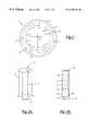
- FIGS. 2A and 2Bare perspective views of a first embodiment of a brake lining wear sensor in accordance with the present invention.
- FIG. 3is a perspective view of a second embodiment of a brake lining wear sensor in accordance with the present invention.
- FIG. 4is a perspective view of a third embodiment of a brake lining wear sensor in accordance with the present invention.
- FIG. 5is a perspective view of a fourth embodiment of a brake lining wear sensor in accordance with the present invention.
- a brake shoe assembly having a brake lining wear sensor in accordance with the present inventionis shown installed in a vehicular brake system.
- the inventive brake shoe assemblyas described below, may be incorporated into several different types of conventional brake systems including, but not limited to, drum brake systems and disc brake systems.
- the brake shoe assemblyhas been illustrated in a drum brake system in FIG. 1 for descriptive purposes only and not to limit the scope of the present invention.
- FIG. 1is a side view of a drum brake system 10 .
- the drum brake system 10includes a cylindrical brake drum 12 , a first brake shoe assembly generally shown at 14 , a second brake shoe assembly generally shown at 16 , and an actuator 18 .
- the general operation of the brake drum assembly 10is known.
- the first and second brake shoe assemblies 14 and 16are preferably identical such that a description of the first brake shoe assembly 14 or its components is also applicable to the second brake shoe assembly 16 .
- the drum brake system 10can be of various types of systems such as an s-cam brake, a wedge brake, or a drum brake actuated by a hydraulic cylinder.
- the actuator 18shown schematically in FIG. 1, represents any known actuating mechanism for drum brake systems such as an scam mechanism, a wedge mechanism, or a hydraulic cylinder.
- the actuator 18moves the first and second brake shoe assemblies 14 and 16 into contact with the rotating brake drum 12 and can be controlled hydraulically or pneumatically.
- the brake drum 12which rotates about an axis of rotation 20 , has an inner surface 22 and an outer surface 24 .
- the first and second brake shoe assemblies 14 and 16located adjacent to the inner surface 22 of the brake drum 12 , include a brake lining 26 having a predetermined thickness.
- the brake linings 26are comprised of a known friction material attached to a backing plate 28 .
- Each brake lining 26presents a wear surface 32 which contacts the inner surface 22 of the rotating brake drum 12 and wears further and further away each time the actuator 18 moves the first and second brake shoe assemblies 14 and 16 against the brake drum 12 . After numerous brake applications, the brake linings 26 wear below a critical thickness and, therefore, must be replaced.
- Each brake lining 26also includes an interface surface 34 which contacts the backing plate 28 .
- a brake lining wear sensor 36shown schematically in FIG. 1, is attached to the backing plate 28 of the first brake shoe assembly 14 .
- the brake lining wear sensor 36is positioned to wear away as the brake lining 26 gradually wears away during brake applications.
- the brake lining wear sensor 36is positioned adjacent to the brake lining 26 .
- the brake lining wear sensor 36may be embedded or encapsulated in the brake lining 26 .
- the brake lining wear sensor 36can be incorporated in either the first and/or the second brake shoe assemblies 14 and 16 , but typically need only be incorporated in the leading brake shoe assembly which experiences the most brake lining wear.
- the brake lining wear sensor 36includes a pair of spaced electrical conductors and an electrical resistance located across the pair of spaced conductors. As the length of the brake lining wear sensor 36 gradually wears away, the electrical resistance across the pair of spaced conductors continuously changes. In this manner, the electrical resistance across the pair of spaced conductors is used to determine the thickness of the brake lining 26 . To accomplish this objective, the brake lining wear sensor 36 is comprised of components having wear properties similar to the wear properties of the brake lining 26 .
- the brake lining wear sensor 36can be assembled in alternative embodiments, wherein like numerals are increased by multiples of 100 to indicate like or corresponding parts.
- FIG. 2Ais a perspective view of a first embodiment of a brake lining wear sensor 136 in accordance with the present invention.
- the brake lining wear sensor 136includes an insulating substrate 138 , a pair of spaced electrical conductors 140 cohered to one surface of the substrate 138 , and a layer of material 142 cohered to the substrate 138 .
- the layer of material 142provides an electrical resistance across the pair of spaced conductors 140 .
- a body of material 144supports the substrate 138 .
- the brake lining wear sensor 136including the substrate 138 , the pair of spaced conductors 140 , the strip of film material 142 , and the body of material 144 , is positioned to wear away concurrently with the brake lining 26 , thereby continuously changing the resistance across the pair of spaced conductors 140 .
- the substrate 138consists of a glass epoxy or a high temperature ceramic.
- a conductorsuch as copper, tin, or tin plated copper, is applied to the substrate 138 and etched to produce the pair of spaced conductors 140 .
- a conductormay be screened or evaporated onto the substrate 138 and etched to produce the pair of spaced conductors 140 .
- the layer of resistance material 142consists of a carbon powder base, commonly referred to as a CERMET compound, which is silk-screened onto the substrate 138 .
- a phenolic potting compound or high temperature cementis used to form the body 144 .
- the pair of conductors 140may be spaced parallel to each other.
- One of ordinary skill in the artwill recognize that the spacing of the pair of conductors 140 determines the rate of change in the resistance across the pair of conductors 140 as the length of the brake lining wear sensor 136 is worn away. Accordingly, the spacing between the conductors 140 may be adapted to achieve a desired rate of change for different applications.
- FIG. 2Bis a perspective view of the substrate 138 covered with an alternative layer of material 142 ′.
- the alternative layer of material 142 ′includes a plurality of adjacent portions 146 , 148 , 150 , 152 , and 154 , each having a unique resistance.
- the adjacent portions 146 , 148 , 150 , 152 , and 154may be arranged to achieve a desired rate of change in the resistance across the pair of spaced conductors 140 as the length of the brake lining wear sensor 136 is worn away.
- the adjacent portions 146 , 148 , 150 , 152 , and 154are positioned diagonal to the pair of spaced conductors 140 , as illustrated in FIG. 2B, to provide a linear rate of change in the resistance across the pair of spaced conductors 140 as the length of the brake lining wear sensor 136 is worn away.
- FIG. 3is a perspective view of a second embodiment of a brake lining wear sensor 236 in accordance with the present invention.
- the brake lining wear sensor 236includes an insulating substrate 238 , a pair of spaced electrical conductors 240 cohered to one surface of the substrate 238 , and a body of material 244 supporting the substrate 238 .
- the body of material 244provides an electrical resistance across the pair of spaced conductors 240 .
- the brake lining wear sensor 236including the substrate 238 , the pair of spaced conductors 240 , and the body of resistive material 244 , is positioned to wear away concurrently with the brake lining 26 , thereby continuously changing the resistance across the pair of spaced conductors 240 .
- the substrate 238consists of a glass epoxy or a high temperature ceramic.
- a conductorsuch as copper, tin, or tin plated copper, is applied to the substrate 238 and etched to produce the pair of spaced conductors 240 .
- a conductormay be screened or evaporated onto the substrate 238 and etched to produce the pair of spaced conductors 240 .
- a compound consisting of approximately thirty percent carbon fiber and seventy percent phenolic resinis used to form the resistive body 244 . Kevlar fibers may be added as an emulsifier.
- a resistive potting compoundtypically a mixture of carbon and an encapsulant such as epoxy, may be used to form the resistive body 244 .
- FIG. 4is a perspective view of a third embodiment of a brake lining wear sensor 336 in accordance with the present invention.
- the brake lining wear sensor 336includes a substrate 338 and a pair of spaced electrical conductors 340 cohered to one surface of the substrate 338 .
- a resistive compoundis mixed in the substrate 338 to provide an electrical resistance across the pair of spaced conductors 340 .
- a body of material 344supports the substrate 338 .
- the brake lining wear sensor 336including the substrate 338 , the pair of spaced conductors 340 , and the body of material 344 , is positioned to wear away concurrently with the brake lining 26 , thereby continuously changing the resistance across the pair of spaced conductors 240 .
- the substrate 338consists of a glass epoxy or a high temperature ceramic mixed with a resistive carbon compound. Copper is laminated to the substrate 338 and etched to produce the pair of spaced conductors 340 . A phenolic potting compound is used to form the body 344 .
- FIG. 5is a perspective view of a fourth embodiment of a brake lining wear sensor 436 in accordance with the present invention.
- the brake lining wear sensor 436includes a frame 456 and a body of material 444 supporting the frame 456 .
- the frame 456includes a pair of spaced electrical conductors 440 and a plurality of support pieces 458 attached between the pair of spaced conductors 440 .
- the body of material 444provides an electrical resistance across the pair of spaced conductors 440 .
- the brake lining wear sensor 436including the frame 456 , the pair of spaced conductors 440 , the plurality of support pieces 458 , and the body of resistive material 444 , is positioned to wear away concurrently with the brake lining 26 , thereby continuously changing the resistance across the pair of spaced conductors 240 .
- the frame 456is made from copper wire.
- the surface of the frame 456is abraded to form a strong electromechanical bond with the body of resistive material 444 .
- a compound consisting of approximately thirty percent carbon fiber and seventy percent phenolic resinis used to form the resistive body 444 .
- Kevlar fibersmay be added as an emulsifier.
- a resistive potting compoundtypically a mixture of carbon and an encapsulant such as epoxy, may be used to form the resistive body 444 .
Landscapes
- Engineering & Computer Science (AREA)
- General Engineering & Computer Science (AREA)
- Mechanical Engineering (AREA)
- Braking Arrangements (AREA)
- Braking Systems And Boosters (AREA)
Abstract
Description
Claims (18)
Priority Applications (3)
| Application Number | Priority Date | Filing Date | Title |
|---|---|---|---|
| US09/169,527US6250429B1 (en) | 1998-10-09 | 1998-10-09 | Brake shoe assembly having a resistive brake lining wear sensor |
| BR9907525-3ABR9907525A (en) | 1998-10-09 | 1999-10-05 | Brake shoe assembly having a brake liner wear resistive sensor |
| EP99119140AEP0992702A3 (en) | 1998-10-09 | 1999-10-05 | Brake shoe assembly having a resistive brake lining wear sensor |
Applications Claiming Priority (1)
| Application Number | Priority Date | Filing Date | Title |
|---|---|---|---|
| US09/169,527US6250429B1 (en) | 1998-10-09 | 1998-10-09 | Brake shoe assembly having a resistive brake lining wear sensor |
Publications (1)
| Publication Number | Publication Date |
|---|---|
| US6250429B1true US6250429B1 (en) | 2001-06-26 |
Family
ID=22616076
Family Applications (1)
| Application Number | Title | Priority Date | Filing Date |
|---|---|---|---|
| US09/169,527Expired - Fee RelatedUS6250429B1 (en) | 1998-10-09 | 1998-10-09 | Brake shoe assembly having a resistive brake lining wear sensor |
Country Status (3)
| Country | Link |
|---|---|
| US (1) | US6250429B1 (en) |
| EP (1) | EP0992702A3 (en) |
| BR (1) | BR9907525A (en) |
Cited By (17)
| Publication number | Priority date | Publication date | Assignee | Title |
|---|---|---|---|---|
| US6477893B1 (en)* | 2000-09-08 | 2002-11-12 | Dana Corporation | Erodable sensor for progressive brake wear detection |
| US6564909B1 (en)* | 1999-05-14 | 2003-05-20 | I.C.P. S.R.L. | Wear detector for a vehicle braking member |
| US20040168864A1 (en)* | 2001-06-27 | 2004-09-02 | Wilfried Strauss | Braking lining wear system |
| US20060131950A1 (en)* | 2004-12-20 | 2006-06-22 | Larson Gerald L | Vehicle onboard brake pad/lining wear estimators with temperature estimations |
| US20070020353A1 (en)* | 2005-07-05 | 2007-01-25 | Hirschmann Automotive Gmbh | Brake-shoe wear sensor |
| US20090107795A1 (en)* | 2007-10-26 | 2009-04-30 | Rolls-Royce Corporation | Material wear indication system |
| US20100017087A1 (en)* | 2006-08-23 | 2010-01-21 | Tmd Friction Services Gmbh | Temperature and wear and tear sensor for brake or clutch devices |
| CN103210232A (en)* | 2010-09-16 | 2013-07-17 | 克诺尔商用车制动系统有限公司 | Wear distance sensor for a brake pad of a friction brake |
| US9371630B1 (en) | 2014-12-19 | 2016-06-21 | Caterpillar Inc. | Determination of undercarriage idler and roller wear based on final drive speed |
| US9475526B2 (en) | 2014-08-23 | 2016-10-25 | Caterpillar Inc. | Track link having a wear sensing device |
| US9557244B2 (en) | 2014-11-10 | 2017-01-31 | Caterpillar Inc. | Thrust bias detection system |
| US9592866B2 (en) | 2014-11-06 | 2017-03-14 | Caterpillar Inc. | Track assembly having a wear monitoring system |
| US9784647B2 (en) | 2014-12-19 | 2017-10-10 | Caterpillar Inc. | Wear sensing device having a housing |
| US9868482B2 (en) | 2014-10-29 | 2018-01-16 | Caterpillar Inc. | Track roller assembly with a wear measurement system |
| US10760634B2 (en)* | 2018-03-22 | 2020-09-01 | Robert Bosch Llc | Brake pad monitor with conductivity measurement |
| CN111779779A (en)* | 2020-06-04 | 2020-10-16 | 吴华 | Brake pad gap adjusting mechanism for automobile |
| EP3743636B1 (en) | 2018-01-24 | 2023-01-18 | KNORR-BREMSE Systeme für Nutzfahrzeuge GmbH | Brake lining wear measuring device for a brake, brake and brake lining set |
Families Citing this family (6)
| Publication number | Priority date | Publication date | Assignee | Title |
|---|---|---|---|---|
| US6360850B1 (en)* | 2000-07-20 | 2002-03-26 | Dana Corporation | Progressive brake lining wear sensor |
| DE502007001281D1 (en)* | 2006-09-22 | 2009-09-24 | Hirschmann Automotive Gmbh | Sensor for detecting the wear of a brake pad of a brake system of a vehicle |
| CN102155509B (en)* | 2011-04-06 | 2012-10-10 | 吉林大学 | Device for detecting wearing capacity of brake shoe of automobile |
| DE102018105057B4 (en)* | 2018-03-06 | 2023-01-12 | Knorr-Bremse Systeme für Nutzfahrzeuge GmbH | Pad wear sensor and brake pad |
| TWI672446B (en)* | 2018-06-26 | 2019-09-21 | 彥豪金屬工業股份有限公司 | Abrasion alert device for brake pad and assembling method thereof |
| DE102021126859B3 (en) | 2021-10-15 | 2023-03-02 | Saf-Holland Gmbh | Brake pad measurement system, brake system and method for determining a condition of a brake system |
Citations (54)
| Publication number | Priority date | Publication date | Assignee | Title |
|---|---|---|---|---|
| US1957051A (en) | 1930-09-24 | 1934-05-01 | Bendix Brake Co | Brake temperature indicator |
| US2117027A (en) | 1935-12-09 | 1938-05-10 | Harold W Langbein | Brake indicating and testing device |
| US2494269A (en) | 1946-10-01 | 1950-01-10 | Spar Holl Mfg Company Inc | Safety device for vehicle brakes |
| US3088549A (en) | 1959-08-25 | 1963-05-07 | Borsa Clelio Carlos | Control and alarm system for brake shoe linings of motor cars and the like |
| US3314618A (en) | 1965-01-14 | 1967-04-18 | Allis Chalmers Mfg Co | Crushing chamber wear indicator |
| US3321045A (en) | 1966-04-11 | 1967-05-23 | Bernard J Veilleux | Brake lining sensing device |
| US3398246A (en) | 1966-06-29 | 1968-08-20 | Linet William | Brake wear alert device |
| US3556258A (en) | 1968-11-06 | 1971-01-19 | Bendix Corp | Brake lining wear indicator |
| US3674114A (en) | 1970-09-11 | 1972-07-04 | Bendix Corp | Brake lining temperature probe |
| US3689880A (en) | 1970-09-16 | 1972-09-05 | Robert G Mckee | Vehicle brake warning device |
| US3800278A (en) | 1972-08-22 | 1974-03-26 | S Jaye | Brake lining wear warning gauge |
| US3805228A (en) | 1972-04-20 | 1974-04-16 | A Peeples | Vehicle brake lining wear indication apparatus |
| US3825891A (en) | 1971-01-16 | 1974-07-23 | Daimler Benz Ag | Brake-lining wear-indicator |
| US3914734A (en) | 1973-05-02 | 1975-10-21 | Gonzalo Rigalt | Brake failure warning device |
| US3958445A (en) | 1973-08-30 | 1976-05-25 | The Bendix Corporation | Proportional brake lining wear sensor |
| US3975706A (en) | 1973-05-04 | 1976-08-17 | Kabushiki Kaisha Toyota Chuo Kenkyusho | Abnormality-detecting device in a brake system |
| US4016533A (en) | 1974-04-26 | 1977-04-05 | Toyota Jidosha Kogyo Kabushiki Kaisha | Device for warning of excessive wear on a brake lining |
| US4020454A (en) | 1976-02-17 | 1977-04-26 | Malonee Arley L | Brake monitoring system |
| US4188613A (en) | 1978-05-31 | 1980-02-12 | Wong Chia Hsiang | Safety indicator for automobile braking system |
| US4204190A (en) | 1977-12-07 | 1980-05-20 | Lucas Industries Limited | Brake pad wear detection system |
| US4241603A (en) | 1979-02-02 | 1980-12-30 | The Bendix Corporation | Aircraft brake thermal sensor |
| US4298857A (en) | 1980-02-01 | 1981-11-03 | Ford Motor Company | Brake wear indicator system |
| JPS5714402A (en) | 1980-06-27 | 1982-01-25 | Daido Steel Co Ltd | Cold rolling method for slitted steel strip |
| US4387789A (en) | 1976-07-21 | 1983-06-14 | Rockwell International Corporation | Electrical brake lining wear indicator |
| US4508196A (en) | 1982-01-18 | 1985-04-02 | Compagnie Generale Des Etablissements Michelin | Wear and licking alarm for crown or disk brake |
| US4520661A (en) | 1983-02-15 | 1985-06-04 | Matsushita Electric Industrial Co., Ltd. | Temperature and wear sensor for a brake |
| US4562421A (en) | 1983-01-31 | 1985-12-31 | Duffy Dennis A | Brake wear sensor |
| FR2574508A1 (en) | 1984-12-11 | 1986-06-13 | Renault | FRICTION TRIM WEAR DETECTOR |
| US4604604A (en) | 1984-06-29 | 1986-08-05 | International Harvester Company | Vapor emitting wear indicator |
| US4606435A (en) | 1984-09-10 | 1986-08-19 | General Motors Corporation | Brake lining wear sensor and indicator circuit |
| US4641519A (en) | 1984-07-13 | 1987-02-10 | Alfred Teves Gmbh | Device for the determination of rotational speed |
| US4646001A (en) | 1983-11-21 | 1987-02-24 | Morganite Electrical Carbon Limited | Resistive wear sensors |
| US4649370A (en) | 1984-06-15 | 1987-03-10 | Thomason Linda R | Brake condition indicator |
| US4658936A (en) | 1985-07-25 | 1987-04-21 | Goodyear Aerospace Corporation | Brake temperature and wear indicator |
| US4674326A (en) | 1985-01-23 | 1987-06-23 | Wabco Westinghouse Fahrzeugbremsen Gmbh | Apparatus for the measuring and/or controlling of the wear on a component |
| US4790606A (en) | 1985-01-23 | 1988-12-13 | Wabco Westinghouse Fahrzeugbremsen Gmbh | Apparatus for the measurement and/or regulation of a braking force and/or of a braking torque |
| US4824260A (en) | 1988-04-13 | 1989-04-25 | Abex Corporation | Brake block temperature and wear measuring device |
| US4869350A (en) | 1987-07-24 | 1989-09-26 | Bendix France | Wear indicator for a friction member of an automotive brake |
| US4964679A (en) | 1988-02-23 | 1990-10-23 | Lucas Industries Public Limited Co. | Monitoring method and apparatus for a brake system of heavy-duty vehicles |
| US4971179A (en) | 1988-07-22 | 1990-11-20 | Knorr-Bremse Ag | Brake device for rail vehicles or trains |
| US5079947A (en) | 1989-09-13 | 1992-01-14 | Wabco Westinghouse Fahrzeugbremsen Gmbh | Method for approximate indication of mean temperature of a component of a brake device |
| US5151681A (en) | 1989-08-25 | 1992-09-29 | General Motors France | Brake wear indicating device |
| US5168260A (en) | 1990-05-31 | 1992-12-01 | Bendix Europe Services Techniques | Wear indicator for a friction lining |
| US5189391A (en) | 1989-09-13 | 1993-02-23 | WABCO Westinghouse Fahrzugbremsen GmbH | Method for the surveillance of a brake device in regard to overload |
| US5302940A (en) | 1992-10-05 | 1994-04-12 | Chen Chi Shan | Motor vehicle brake detector |
| US5307673A (en) | 1991-12-13 | 1994-05-03 | Sumitomo Wiring Systems, Ltd. | Wear-detection probe for a brake lining material |
| US5372221A (en) | 1992-07-20 | 1994-12-13 | Otis Elevator Company | Active brake sensor |
| US5417312A (en)* | 1990-05-30 | 1995-05-23 | Hitachi, Ltd. | Semiconductor acceleration sensor and vehicle control system using the same |
| US5419415A (en) | 1992-12-21 | 1995-05-30 | Inventio Ag | Apparatus for monitoring elevator brakes |
| US5550743A (en) | 1995-02-15 | 1996-08-27 | Eaton Corporation | Geographic locator of a vehicle using GPS and angles between pairs of adjacent boundary coordinate points |
| US5559286A (en) | 1995-10-10 | 1996-09-24 | Eaton Corporation | Vehicle friction material condition measurement system |
| US5637794A (en) | 1995-12-22 | 1997-06-10 | Eaton Corporation | Resistive brake lining wear and temperature sensing system |
| US5651431A (en) | 1996-01-26 | 1997-07-29 | Eaton Corporation | Method of brake lining wear detection using temperature sensing |
| US5668529A (en) | 1996-06-05 | 1997-09-16 | Eaton Corporation | Method of statistically determining brake lining wear using temperature sensing |
Family Cites Families (3)
| Publication number | Priority date | Publication date | Assignee | Title |
|---|---|---|---|---|
| JPS57144402A (en)* | 1981-03-02 | 1982-09-07 | Akebono Brake Ind Co Ltd | Sensor for detecting abrasion loss of brake lining |
| DE3915996C1 (en)* | 1989-02-21 | 1990-06-28 | Leopold Kostal Gmbh & Co Kg, 5880 Luedenscheid, De | Vehicle brake limiting wear sensor - has thick-film resistor on ceramic substrate fixed in opening of brake lining |
| DE3905190C1 (en)* | 1989-02-21 | 1990-05-10 | Leopold Kostal Gmbh & Co Kg, 5880 Luedenscheid, De | Sensor device |
- 1998
- 1998-10-09USUS09/169,527patent/US6250429B1/ennot_activeExpired - Fee Related
- 1999
- 1999-10-05BRBR9907525-3Apatent/BR9907525A/ennot_activeIP Right Cessation
- 1999-10-05EPEP99119140Apatent/EP0992702A3/ennot_activeWithdrawn
Patent Citations (54)
| Publication number | Priority date | Publication date | Assignee | Title |
|---|---|---|---|---|
| US1957051A (en) | 1930-09-24 | 1934-05-01 | Bendix Brake Co | Brake temperature indicator |
| US2117027A (en) | 1935-12-09 | 1938-05-10 | Harold W Langbein | Brake indicating and testing device |
| US2494269A (en) | 1946-10-01 | 1950-01-10 | Spar Holl Mfg Company Inc | Safety device for vehicle brakes |
| US3088549A (en) | 1959-08-25 | 1963-05-07 | Borsa Clelio Carlos | Control and alarm system for brake shoe linings of motor cars and the like |
| US3314618A (en) | 1965-01-14 | 1967-04-18 | Allis Chalmers Mfg Co | Crushing chamber wear indicator |
| US3321045A (en) | 1966-04-11 | 1967-05-23 | Bernard J Veilleux | Brake lining sensing device |
| US3398246A (en) | 1966-06-29 | 1968-08-20 | Linet William | Brake wear alert device |
| US3556258A (en) | 1968-11-06 | 1971-01-19 | Bendix Corp | Brake lining wear indicator |
| US3674114A (en) | 1970-09-11 | 1972-07-04 | Bendix Corp | Brake lining temperature probe |
| US3689880A (en) | 1970-09-16 | 1972-09-05 | Robert G Mckee | Vehicle brake warning device |
| US3825891A (en) | 1971-01-16 | 1974-07-23 | Daimler Benz Ag | Brake-lining wear-indicator |
| US3805228A (en) | 1972-04-20 | 1974-04-16 | A Peeples | Vehicle brake lining wear indication apparatus |
| US3800278A (en) | 1972-08-22 | 1974-03-26 | S Jaye | Brake lining wear warning gauge |
| US3914734A (en) | 1973-05-02 | 1975-10-21 | Gonzalo Rigalt | Brake failure warning device |
| US3975706A (en) | 1973-05-04 | 1976-08-17 | Kabushiki Kaisha Toyota Chuo Kenkyusho | Abnormality-detecting device in a brake system |
| US3958445A (en) | 1973-08-30 | 1976-05-25 | The Bendix Corporation | Proportional brake lining wear sensor |
| US4016533A (en) | 1974-04-26 | 1977-04-05 | Toyota Jidosha Kogyo Kabushiki Kaisha | Device for warning of excessive wear on a brake lining |
| US4020454A (en) | 1976-02-17 | 1977-04-26 | Malonee Arley L | Brake monitoring system |
| US4387789A (en) | 1976-07-21 | 1983-06-14 | Rockwell International Corporation | Electrical brake lining wear indicator |
| US4204190A (en) | 1977-12-07 | 1980-05-20 | Lucas Industries Limited | Brake pad wear detection system |
| US4188613A (en) | 1978-05-31 | 1980-02-12 | Wong Chia Hsiang | Safety indicator for automobile braking system |
| US4241603A (en) | 1979-02-02 | 1980-12-30 | The Bendix Corporation | Aircraft brake thermal sensor |
| US4298857A (en) | 1980-02-01 | 1981-11-03 | Ford Motor Company | Brake wear indicator system |
| JPS5714402A (en) | 1980-06-27 | 1982-01-25 | Daido Steel Co Ltd | Cold rolling method for slitted steel strip |
| US4508196A (en) | 1982-01-18 | 1985-04-02 | Compagnie Generale Des Etablissements Michelin | Wear and licking alarm for crown or disk brake |
| US4562421A (en) | 1983-01-31 | 1985-12-31 | Duffy Dennis A | Brake wear sensor |
| US4520661A (en) | 1983-02-15 | 1985-06-04 | Matsushita Electric Industrial Co., Ltd. | Temperature and wear sensor for a brake |
| US4646001A (en) | 1983-11-21 | 1987-02-24 | Morganite Electrical Carbon Limited | Resistive wear sensors |
| US4649370A (en) | 1984-06-15 | 1987-03-10 | Thomason Linda R | Brake condition indicator |
| US4604604A (en) | 1984-06-29 | 1986-08-05 | International Harvester Company | Vapor emitting wear indicator |
| US4641519A (en) | 1984-07-13 | 1987-02-10 | Alfred Teves Gmbh | Device for the determination of rotational speed |
| US4606435A (en) | 1984-09-10 | 1986-08-19 | General Motors Corporation | Brake lining wear sensor and indicator circuit |
| FR2574508A1 (en) | 1984-12-11 | 1986-06-13 | Renault | FRICTION TRIM WEAR DETECTOR |
| US4674326A (en) | 1985-01-23 | 1987-06-23 | Wabco Westinghouse Fahrzeugbremsen Gmbh | Apparatus for the measuring and/or controlling of the wear on a component |
| US4790606A (en) | 1985-01-23 | 1988-12-13 | Wabco Westinghouse Fahrzeugbremsen Gmbh | Apparatus for the measurement and/or regulation of a braking force and/or of a braking torque |
| US4658936A (en) | 1985-07-25 | 1987-04-21 | Goodyear Aerospace Corporation | Brake temperature and wear indicator |
| US4869350A (en) | 1987-07-24 | 1989-09-26 | Bendix France | Wear indicator for a friction member of an automotive brake |
| US4964679A (en) | 1988-02-23 | 1990-10-23 | Lucas Industries Public Limited Co. | Monitoring method and apparatus for a brake system of heavy-duty vehicles |
| US4824260A (en) | 1988-04-13 | 1989-04-25 | Abex Corporation | Brake block temperature and wear measuring device |
| US4971179A (en) | 1988-07-22 | 1990-11-20 | Knorr-Bremse Ag | Brake device for rail vehicles or trains |
| US5151681A (en) | 1989-08-25 | 1992-09-29 | General Motors France | Brake wear indicating device |
| US5079947A (en) | 1989-09-13 | 1992-01-14 | Wabco Westinghouse Fahrzeugbremsen Gmbh | Method for approximate indication of mean temperature of a component of a brake device |
| US5189391A (en) | 1989-09-13 | 1993-02-23 | WABCO Westinghouse Fahrzugbremsen GmbH | Method for the surveillance of a brake device in regard to overload |
| US5417312A (en)* | 1990-05-30 | 1995-05-23 | Hitachi, Ltd. | Semiconductor acceleration sensor and vehicle control system using the same |
| US5168260A (en) | 1990-05-31 | 1992-12-01 | Bendix Europe Services Techniques | Wear indicator for a friction lining |
| US5307673A (en) | 1991-12-13 | 1994-05-03 | Sumitomo Wiring Systems, Ltd. | Wear-detection probe for a brake lining material |
| US5372221A (en) | 1992-07-20 | 1994-12-13 | Otis Elevator Company | Active brake sensor |
| US5302940A (en) | 1992-10-05 | 1994-04-12 | Chen Chi Shan | Motor vehicle brake detector |
| US5419415A (en) | 1992-12-21 | 1995-05-30 | Inventio Ag | Apparatus for monitoring elevator brakes |
| US5550743A (en) | 1995-02-15 | 1996-08-27 | Eaton Corporation | Geographic locator of a vehicle using GPS and angles between pairs of adjacent boundary coordinate points |
| US5559286A (en) | 1995-10-10 | 1996-09-24 | Eaton Corporation | Vehicle friction material condition measurement system |
| US5637794A (en) | 1995-12-22 | 1997-06-10 | Eaton Corporation | Resistive brake lining wear and temperature sensing system |
| US5651431A (en) | 1996-01-26 | 1997-07-29 | Eaton Corporation | Method of brake lining wear detection using temperature sensing |
| US5668529A (en) | 1996-06-05 | 1997-09-16 | Eaton Corporation | Method of statistically determining brake lining wear using temperature sensing |
Cited By (20)
| Publication number | Priority date | Publication date | Assignee | Title |
|---|---|---|---|---|
| US6564909B1 (en)* | 1999-05-14 | 2003-05-20 | I.C.P. S.R.L. | Wear detector for a vehicle braking member |
| US6477893B1 (en)* | 2000-09-08 | 2002-11-12 | Dana Corporation | Erodable sensor for progressive brake wear detection |
| US20040168864A1 (en)* | 2001-06-27 | 2004-09-02 | Wilfried Strauss | Braking lining wear system |
| US20060131950A1 (en)* | 2004-12-20 | 2006-06-22 | Larson Gerald L | Vehicle onboard brake pad/lining wear estimators with temperature estimations |
| US7244003B2 (en) | 2004-12-20 | 2007-07-17 | International Truck Intellectual Property Company, Llc | Vehicle onboard brake pad/lining wear estimators with temperature estimations |
| US20070020353A1 (en)* | 2005-07-05 | 2007-01-25 | Hirschmann Automotive Gmbh | Brake-shoe wear sensor |
| US20100017087A1 (en)* | 2006-08-23 | 2010-01-21 | Tmd Friction Services Gmbh | Temperature and wear and tear sensor for brake or clutch devices |
| US8437934B2 (en)* | 2006-08-23 | 2013-05-07 | Tmd Friction Services Gmbh | Temperature and wear and tear sensor for brake or clutch devices |
| US20090107795A1 (en)* | 2007-10-26 | 2009-04-30 | Rolls-Royce Corporation | Material wear indication system |
| US7847679B2 (en)* | 2007-10-26 | 2010-12-07 | Rolls-Royce Corporation | Material wear indication system |
| CN103210232A (en)* | 2010-09-16 | 2013-07-17 | 克诺尔商用车制动系统有限公司 | Wear distance sensor for a brake pad of a friction brake |
| US9475526B2 (en) | 2014-08-23 | 2016-10-25 | Caterpillar Inc. | Track link having a wear sensing device |
| US9868482B2 (en) | 2014-10-29 | 2018-01-16 | Caterpillar Inc. | Track roller assembly with a wear measurement system |
| US9592866B2 (en) | 2014-11-06 | 2017-03-14 | Caterpillar Inc. | Track assembly having a wear monitoring system |
| US9557244B2 (en) | 2014-11-10 | 2017-01-31 | Caterpillar Inc. | Thrust bias detection system |
| US9371630B1 (en) | 2014-12-19 | 2016-06-21 | Caterpillar Inc. | Determination of undercarriage idler and roller wear based on final drive speed |
| US9784647B2 (en) | 2014-12-19 | 2017-10-10 | Caterpillar Inc. | Wear sensing device having a housing |
| EP3743636B1 (en) | 2018-01-24 | 2023-01-18 | KNORR-BREMSE Systeme für Nutzfahrzeuge GmbH | Brake lining wear measuring device for a brake, brake and brake lining set |
| US10760634B2 (en)* | 2018-03-22 | 2020-09-01 | Robert Bosch Llc | Brake pad monitor with conductivity measurement |
| CN111779779A (en)* | 2020-06-04 | 2020-10-16 | 吴华 | Brake pad gap adjusting mechanism for automobile |
Also Published As
| Publication number | Publication date |
|---|---|
| EP0992702A3 (en) | 2000-07-26 |
| BR9907525A (en) | 2000-08-15 |
| EP0992702A2 (en) | 2000-04-12 |
Similar Documents
| Publication | Publication Date | Title |
|---|---|---|
| US6250429B1 (en) | Brake shoe assembly having a resistive brake lining wear sensor | |
| US6257374B1 (en) | Brake pad wear sensing system and method | |
| KR100374432B1 (en) | Wear indicator of brake lining | |
| US4850454A (en) | Disc brake lining wear sensor | |
| US4926978A (en) | Friction pad for use with disc brake | |
| EP0337919B1 (en) | Brake block temperature and wear measuring device | |
| US4715486A (en) | Low-wear frictionally engaging device | |
| US4491204A (en) | Disk brake with return, guide, and pad-thickness sensor spring | |
| US6450300B1 (en) | Packaging a temperature sensing brake lining wear indicator in a brake shoe assembly | |
| US20020153214A1 (en) | Friction disc and process for producing the same | |
| HU207381B (en) | Disc brake of divided insert | |
| GB2212571A (en) | Friction brakes | |
| US6637262B2 (en) | Electrical wear sensor for disc brake | |
| US8191973B2 (en) | Method for the creation of a pole wheel/wheel hub connection and arrangement thereof | |
| KR20120099624A (en) | Caliper of a disk brake | |
| EP1265002B1 (en) | Brake pad | |
| US6260665B1 (en) | System and method for determining brake lining wear based on cooling wave propagation time | |
| EP0999377B1 (en) | Brake shoe assembly having a brake lining wear and temperature sensor | |
| EP1272772A1 (en) | Braking components, particularly for vehicle brakes | |
| US5236068A (en) | Mid-radius disc brake shoe contact pads | |
| KR102858484B1 (en) | Braking and/or clamping device with integrated split housing and sensor module | |
| GB2219365A (en) | Friction pad for use with disc brake | |
| US20040168864A1 (en) | Braking lining wear system | |
| US4976339A (en) | Disc brake and support system for such a brake | |
| GB2058968A (en) | Brake pad |
Legal Events
| Date | Code | Title | Description |
|---|---|---|---|
| AS | Assignment | Owner name:MERITOR HEAVY VEHICLE SYSTEMS, LLC, MICHIGAN Free format text:ASSIGNMENT OF ASSIGNORS INTEREST;ASSIGNOR:KRAMER, DENNIS A.;REEL/FRAME:009512/0478 Effective date:19981007 | |
| FPAY | Fee payment | Year of fee payment:4 | |
| AS | Assignment | Owner name:JPMORGAN CHASE BANK, NATIONAL ASSOCIATION, FOR ITS Free format text:SECURITY AGREEMENT;ASSIGNOR:MERITOR HEAVY VEHICLE SYSTEMS, LLC;REEL/FRAME:018524/0770 Effective date:20060823 | |
| REMI | Maintenance fee reminder mailed | ||
| LAPS | Lapse for failure to pay maintenance fees | ||
| STCH | Information on status: patent discontinuation | Free format text:PATENT EXPIRED DUE TO NONPAYMENT OF MAINTENANCE FEES UNDER 37 CFR 1.362 | |
| FP | Lapsed due to failure to pay maintenance fee | Effective date:20090626 | |
| AS | Assignment | Owner name:AXLETECH INTERNATIONAL IP HOLDINGS, LLC, MICHIGAN Free format text:RELEASE BY SECURED PARTY;ASSIGNOR:JPMORGAN CHASE BANK, N.A., AS ADMINISTRATIVE AGENT;REEL/FRAME:061521/0550 Effective date:20220803 Owner name:MERITOR TECHNOLOGY, LLC, MICHIGAN Free format text:RELEASE BY SECURED PARTY;ASSIGNOR:JPMORGAN CHASE BANK, N.A., AS ADMINISTRATIVE AGENT;REEL/FRAME:061521/0550 Effective date:20220803 Owner name:MOTOR HEAVY VEHICLE SYSTEMS, LLC, MICHIGAN Free format text:RELEASE BY SECURED PARTY;ASSIGNOR:JPMORGAN CHASE BANK, N.A., AS ADMINISTRATIVE AGENT;REEL/FRAME:061521/0550 Effective date:20220803 Owner name:ARVINMERITOR OE, LLC, MICHIGAN Free format text:RELEASE BY SECURED PARTY;ASSIGNOR:JPMORGAN CHASE BANK, N.A., AS ADMINISTRATIVE AGENT;REEL/FRAME:061521/0550 Effective date:20220803 Owner name:MERITOR HEAVY VEHICLE SYSTEMS, LLC, MICHIGAN Free format text:RELEASE BY SECURED PARTY;ASSIGNOR:JPMORGAN CHASE BANK, N.A., AS ADMINISTRATIVE AGENT;REEL/FRAME:061521/0550 Effective date:20220803 Owner name:ARVINMERITOR TECHNOLOGY, LLC, MICHIGAN Free format text:RELEASE BY SECURED PARTY;ASSIGNOR:JPMORGAN CHASE BANK, N.A., AS ADMINISTRATIVE AGENT;REEL/FRAME:061521/0550 Effective date:20220803 Owner name:MAREMOUNT CORPORATION, MICHIGAN Free format text:RELEASE BY SECURED PARTY;ASSIGNOR:JPMORGAN CHASE BANK, N.A., AS ADMINISTRATIVE AGENT;REEL/FRAME:061521/0550 Effective date:20220803 Owner name:EUCLID INDUSTRIES, LLC, MICHIGAN Free format text:RELEASE BY SECURED PARTY;ASSIGNOR:JPMORGAN CHASE BANK, N.A., AS ADMINISTRATIVE AGENT;REEL/FRAME:061521/0550 Effective date:20220803 Owner name:GABRIEL RIDE CONTROL PRODUCTS, INC., MICHIGAN Free format text:RELEASE BY SECURED PARTY;ASSIGNOR:JPMORGAN CHASE BANK, N.A., AS ADMINISTRATIVE AGENT;REEL/FRAME:061521/0550 Effective date:20220803 Owner name:ARVIN TECHNOLOGIES, INC., MICHIGAN Free format text:RELEASE BY SECURED PARTY;ASSIGNOR:JPMORGAN CHASE BANK, N.A., AS ADMINISTRATIVE AGENT;REEL/FRAME:061521/0550 Effective date:20220803 Owner name:MERITOR TRANSMISSION CORPORATION, MICHIGAN Free format text:RELEASE BY SECURED PARTY;ASSIGNOR:JPMORGAN CHASE BANK, N.A., AS ADMINISTRATIVE AGENT;REEL/FRAME:061521/0550 Effective date:20220803 Owner name:ARVINMERITOR, INC., MICHIGAN Free format text:RELEASE BY SECURED PARTY;ASSIGNOR:JPMORGAN CHASE BANK, N.A., AS ADMINISTRATIVE AGENT;REEL/FRAME:061521/0550 Effective date:20220803 |