US6250422B1 - Dual cross-flow muffler - Google Patents
Dual cross-flow mufflerDownload PDFInfo
- Publication number
- US6250422B1 US6250422B1US09/436,576US43657699AUS6250422B1US 6250422 B1US6250422 B1US 6250422B1US 43657699 AUS43657699 AUS 43657699AUS 6250422 B1US6250422 B1US 6250422B1
- Authority
- US
- United States
- Prior art keywords
- upstream
- inner baffle
- downstream
- expansion chamber
- apertures
- Prior art date
- Legal status (The legal status is an assumption and is not a legal conclusion. Google has not performed a legal analysis and makes no representation as to the accuracy of the status listed.)
- Expired - Lifetime
Links
Images


Classifications
- F—MECHANICAL ENGINEERING; LIGHTING; HEATING; WEAPONS; BLASTING
- F01—MACHINES OR ENGINES IN GENERAL; ENGINE PLANTS IN GENERAL; STEAM ENGINES
- F01N—GAS-FLOW SILENCERS OR EXHAUST APPARATUS FOR MACHINES OR ENGINES IN GENERAL; GAS-FLOW SILENCERS OR EXHAUST APPARATUS FOR INTERNAL-COMBUSTION ENGINES
- F01N13/00—Exhaust or silencing apparatus characterised by constructional features
- F01N13/18—Construction facilitating manufacture, assembly, or disassembly
- F01N13/1872—Construction facilitating manufacture, assembly, or disassembly the assembly using stamp-formed parts or otherwise deformed sheet-metal
- F—MECHANICAL ENGINEERING; LIGHTING; HEATING; WEAPONS; BLASTING
- F01—MACHINES OR ENGINES IN GENERAL; ENGINE PLANTS IN GENERAL; STEAM ENGINES
- F01N—GAS-FLOW SILENCERS OR EXHAUST APPARATUS FOR MACHINES OR ENGINES IN GENERAL; GAS-FLOW SILENCERS OR EXHAUST APPARATUS FOR INTERNAL-COMBUSTION ENGINES
- F01N1/00—Silencing apparatus characterised by method of silencing
- F01N1/06—Silencing apparatus characterised by method of silencing by using interference effect
- F—MECHANICAL ENGINEERING; LIGHTING; HEATING; WEAPONS; BLASTING
- F01—MACHINES OR ENGINES IN GENERAL; ENGINE PLANTS IN GENERAL; STEAM ENGINES
- F01N—GAS-FLOW SILENCERS OR EXHAUST APPARATUS FOR MACHINES OR ENGINES IN GENERAL; GAS-FLOW SILENCERS OR EXHAUST APPARATUS FOR INTERNAL-COMBUSTION ENGINES
- F01N1/00—Silencing apparatus characterised by method of silencing
- F01N1/08—Silencing apparatus characterised by method of silencing by reducing exhaust energy by throttling or whirling
- F01N1/084—Silencing apparatus characterised by method of silencing by reducing exhaust energy by throttling or whirling the exhaust gases flowing through the silencer two or more times longitudinally in opposite directions, e.g. using parallel or concentric tubes
- F—MECHANICAL ENGINEERING; LIGHTING; HEATING; WEAPONS; BLASTING
- F01—MACHINES OR ENGINES IN GENERAL; ENGINE PLANTS IN GENERAL; STEAM ENGINES
- F01N—GAS-FLOW SILENCERS OR EXHAUST APPARATUS FOR MACHINES OR ENGINES IN GENERAL; GAS-FLOW SILENCERS OR EXHAUST APPARATUS FOR INTERNAL-COMBUSTION ENGINES
- F01N1/00—Silencing apparatus characterised by method of silencing
- F01N1/08—Silencing apparatus characterised by method of silencing by reducing exhaust energy by throttling or whirling
- F01N1/089—Silencing apparatus characterised by method of silencing by reducing exhaust energy by throttling or whirling using two or more expansion chambers in series
- F—MECHANICAL ENGINEERING; LIGHTING; HEATING; WEAPONS; BLASTING
- F01—MACHINES OR ENGINES IN GENERAL; ENGINE PLANTS IN GENERAL; STEAM ENGINES
- F01N—GAS-FLOW SILENCERS OR EXHAUST APPARATUS FOR MACHINES OR ENGINES IN GENERAL; GAS-FLOW SILENCERS OR EXHAUST APPARATUS FOR INTERNAL-COMBUSTION ENGINES
- F01N13/00—Exhaust or silencing apparatus characterised by constructional features
- F01N13/18—Construction facilitating manufacture, assembly, or disassembly
- F01N13/1838—Construction facilitating manufacture, assembly, or disassembly characterised by the type of connection between parts of exhaust or silencing apparatus, e.g. between housing and tubes, between tubes and baffles
- F01N13/1844—Mechanical joints
- F01N13/185—Mechanical joints the connection being realised by deforming housing, tube, baffle, plate, or parts thereof
- F—MECHANICAL ENGINEERING; LIGHTING; HEATING; WEAPONS; BLASTING
- F01—MACHINES OR ENGINES IN GENERAL; ENGINE PLANTS IN GENERAL; STEAM ENGINES
- F01N—GAS-FLOW SILENCERS OR EXHAUST APPARATUS FOR MACHINES OR ENGINES IN GENERAL; GAS-FLOW SILENCERS OR EXHAUST APPARATUS FOR INTERNAL-COMBUSTION ENGINES
- F01N13/00—Exhaust or silencing apparatus characterised by constructional features
- F01N13/18—Construction facilitating manufacture, assembly, or disassembly
- F01N13/1888—Construction facilitating manufacture, assembly, or disassembly the housing of the assembly consisting of two or more parts, e.g. two half-shells
- F—MECHANICAL ENGINEERING; LIGHTING; HEATING; WEAPONS; BLASTING
- F01—MACHINES OR ENGINES IN GENERAL; ENGINE PLANTS IN GENERAL; STEAM ENGINES
- F01N—GAS-FLOW SILENCERS OR EXHAUST APPARATUS FOR MACHINES OR ENGINES IN GENERAL; GAS-FLOW SILENCERS OR EXHAUST APPARATUS FOR INTERNAL-COMBUSTION ENGINES
- F01N2470/00—Structure or shape of exhaust gas passages, pipes or tubes
- F01N2470/16—Plurality of inlet tubes, e.g. discharging into different chambers
- F—MECHANICAL ENGINEERING; LIGHTING; HEATING; WEAPONS; BLASTING
- F01—MACHINES OR ENGINES IN GENERAL; ENGINE PLANTS IN GENERAL; STEAM ENGINES
- F01N—GAS-FLOW SILENCERS OR EXHAUST APPARATUS FOR MACHINES OR ENGINES IN GENERAL; GAS-FLOW SILENCERS OR EXHAUST APPARATUS FOR INTERNAL-COMBUSTION ENGINES
- F01N2490/00—Structure, disposition or shape of gas-chambers
- F01N2490/02—Two or more expansion chambers in series connected by means of tubes
- F01N2490/04—Two or more expansion chambers in series connected by means of tubes the gases flowing longitudinally from inlet to outlet only in one direction
Definitions
- the inventionrelates to noise-silencing mufflers.
- the inventionarose during continuing muffler development efforts, including further development efforts directed to the subject matter of the noted parent application.
- the invention of the noted parent applicationarose during muffler development efforts, including those directed to solving problems in box-style mufflers, including muffler shell noise and poor muffler silencing. Since cost is almost always a concern, the solution to the two noted problems must also be cost effective. Box-style or stamped mufflers tend to radiate noise from their flat exterior surfaces. This characteristic is called shell noise and is most often a concern because of its harsh sound and adverse effects on muffler silencing. Also of concern with stamped mufflers is overall acoustic effectiveness. Because these types of mufflers are often constrained to a certain size and shape, their physical layout is not always conducive to good silencing.
- the invention of the parent applicationaddresses and solves the noted problems in a particularly cost effective manner using a simple design.
- the parent inventionenables usage of identical parts within the muffler, which improves manufacturing efficiency and provides a cost reduction. Assembly of the muffler is also easy because the majority of the muffler's internal parts are designed into cross flow baffles.
- the flow from the inletis directed into one of two interior chambers of the muffler, formed by placing two of the cross flow baffles back to back. By letting the exhaust expand first in an interior chamber, the pressure pulses from the engine are less likely to cause exterior noise problems since they are damped considerably before reaching the muffler's outer shells.
- Stiffening bossesmay be provided on larger flat areas of the baffles to control internal shell noise.
- four chambersare created within the muffler by using a twin baffle design, along with two additional volumes between the outer shells and baffles.
- a horseshoe-shaped cross flow baffleis designed to provide the twin internal silencing chambers with desired flow path and area between them. The configuration increases the acoustical effectiveness of the muffler.
- the present inventionprovides further improvements in both performance and lowered cost.
- the muffler design of the present inventionprovides optimization for the majority of small engine applications.
- cost reductionis facilitated by the use of identical internal components.
- Performance gainsare enabled by alternate flow routes designed into paired baffles, together with increased expansion chamber volume conducive to better silencing characteristics.
- the internal bafflesdivide respective chambers between themselves into a main chamber and subchambers and have respective sets of slots or apertures offset from each other and aligned with a respective subchamber. The offset forces the exhaust to turn as it travels into and out of the main chamber, enhancing acoustic silencing.
- Each bafflehas a drawn center area dividing the volume between the outer shells of the muffler and the center chamber, allowing for more expansion and contraction of exhaust gas, enhancing acoustic silencing.
- An area between the top shell and the inner baffleprovides a flow path forcing hot exhaust gas toward the surface of the top shell, enhancing cooling of the exhaust flow.
- the large surface area of the bodyhelps minimize afterfiring, which is an undesirable bang or pop prevalent in small engines at shut down.
- Smaller drawn areas in the bafflesprovide additional chambers affording an alternate flow path for exhaust gas, lowering backpressure.
- the top shellis sloped for shedding debris, such as grass and dirt, which is desirable for lawn tractor applications.
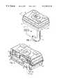
- FIG. 1is an isometric elevational view of a muffler constructed in accordance with the invention of the noted parent application.
- FIG. 2is an exploded perspective view of the structure of FIG. 1 .
- FIG. 3is a view like FIG. 1, partially cut away.
- FIG. 4is another view like FIG. 1, partially cut away.
- FIG. 5is a sectional view taken along line 5 — 5 of FIG. 1 .
- FIG. 6is a sectional view taken along line 6 — 6 of FIG. 5 .
- FIG. 7is a sectional view taken along line 7 — 7 of FIG. 5 .
- FIG. 8is a sectional view taken along line 8 — 8 of FIG. 6 .
- FIG. 9is a sectional view taken along line 9 — 9 of FIG. 5 .
- FIG. 10is a sectional view taken alone line 10 — 10 of FIG. 6 .
- FIG. 11is an isometric elevational view of a muffler constructed in accordance with the present invention.
- FIG. 12is an exploded perspective view of the structure of FIG. 11 .
- FIG. 13is a sectional view taken along line 13 — 13 of FIG. 11 .
- FIG. 14is a sectional view taken along line 14 — 14 of FIG. 13 .
- FIG. 15is a sectional view taken along line 15 — 15 of FIG. 14 .
- FIG. 16is a sectional view taken along line 16 — 16 of FIG. 14 .
- FIG. 17is a sectional view taken along line 17 — 17 of FIG. 14 .
- FIG. 18is an enlarged view of a portion of the structure of FIG. 13 as shown at line 18 — 18 .
- FIG. 19is a bottom isometric elevational view of the muffler of FIG. 11 and showing an additional bottom exhaust directive plate.
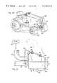
- FIG. 20shows one application of the present invention on a lawn tractor.
- FIG. 21is a view taken along line 21 — 21 of FIG. 20 .
- FIG. 1shows a muffler 12 , FIG. 1, have first and second outer shell members 14 and 16 , FIG. 2, and first and second inner baffle members 18 and 20 .
- Inner baffle members 18 and 20are identical to each other and extend parallel to each other in mirror image relation and rotated 180° relative to each other about an axis 22 perpendicular to such parallel extension.
- Inner baffle member 18has first and second exhaust passages 24 and 26 therethrough.
- Inner baffle member 20has first and second exhaust passages 28 and 30 therethrough. Exhaust passage 26 through inner baffle 18 is aligned with exhaust passage 30 through inner baffle member 20 along axis 22 . Exhaust passages 24 and 28 are laterally offset from each other and from exhaust passages 26 , 30 .
- Each of the inner baffle members 18 , 20has an expansion chamber 32 , 34 , respectively.
- Exhaust passage 24 through inner baffle member 18opens into expansion chamber 34 of inner baffle member 20 .
- Exhaust passage 28 through inner baffle member 20opens into expansion chamber 32 of inner baffle member 18 .
- Expansion chambers 32 , 34are formed in respective baffle members 18 , 20 during stamping, preferably by known deep draw cold forming, and have portions laterally offset from each other, and have portions partially overlapped to provide exhaust flow communication therebetween. Exhaust flow passages 26 , 30 are laterally offset from each of the expansion chambers. Expansion chamber 32 is horseshoe-shaped and has a central bight 36 and a pair of spaced arms 38 and 40 extending therefrom. Expansion chamber 34 is a identical and is horseshoe-shaped and has a central bight 42 and a pair of spaced arms 44 and 46 extending therefrom. Exhaust passages 26 , 30 extend between the spaced arms 38 and 40 , and 44 and 46 of each expansion chamber 32 and 34 , respectively. Spaced arms 38 and 40 of expansion chamber 32 are overlapped respectively with spaced arms 44 and 46 of expansion chamber 34 .
- the exhaust flow pathextends axially forwardly, which is upwardly as shown at arrow 52 in FIGS. 1-3 and 5 , through opening 54 in outer shell number 14 then along inlet exhaust tube 56 through exhaust passage 24 through inner baffle member 18 into expansion chamber 34 of inner baffle member 20 then laterally as shown at arrow 58 , FIGS.
- exhaust flow from expansion chamber 34 of inner baffle member 20is split into spaced parallel paths, namely a first path through arms 46 and 40 , and a second path through arms 44 and 38 .
- the exhaust flow path extending axially forwardly, upwardly in FIGS. 1-6, through inner baffle members 18 and 20 from chamber 86extends between and parallel to such spaced parallel paths and in opposite flow direction relative thereto.
- Inlet exhaust tube 56extends axially through outer shell member 14 and inner baffle member 18 and terminates in expansion chamber 34 of inner baffle member 20 .
- Outlet exhaust tube 94extends axially through outer shell member 16 and inner baffle members 20 and 18 and terminates in chamber 86 .
- Internal transfer tube 66extends axially through inner baffle member 20 , and has an upstream end 99 terminating in expansion chamber 32 of inner baffle member 18 , and has a downstream end 100 terminating in chamber 72 .
- Aligned apertures 80 and 78 , and 84 and 82provide a plurality of exhaust flow passages extending axially rearwardly from chamber 72 to chamber 86 , arrows 74 and 76 , FIG. 6, parallel to outlet exhaust tube 94 and conducting exhaust flow in the opposite direction relative thereto.
- Expansion chambers 34 and 32overlap at the noted pair of portions, namely a first portion through arms 46 and 40 , and a second portion through arms 44 and 38 , which portions are laterally spaced on opposite sides of outlet exhaust tube 94 .
- Inlet exhaust tube 56conducts exhaust flow axially forwardly into the muffler as shown at arrow 52 .
- Inlet exhaust tube 56 and exhaust pipe 50are preferably welded to outer shell 14 , as shown at weldment 102 , FIG. 9, or alternatively by mechanical crimping, or other various known attachment techniques.
- Inlet exhaust tube 56extends through outer shell member 14 at opening 54 and though inner baffle member 18 at passage 24 and has an inner end 104 facing inner baffle member 20 in expansion chamber 34 .
- Inner end 104is preferably spaced by a small gap 106 , FIG. 5, from inner baffle member 20 . In an alternate embodiment, inner end 104 engages inner baffle member 20 in expansion chamber 34 with no gap 106 therebetween.
- Inner baffle member 20is axially between inner end 104 of inlet exhaust tube 56 and outer shell member 16 . There is a gap 108 between outer shell member 16 and inner baffle member 20 at expansion chamber 34 , which gap 108 forms part of chamber 72 .
- Outlet exhaust tube 94conducts exhaust flow axially out of the muffler as shown at arrow 96 . Outlet exhaust tube 94 extends through outer shell member 16 at opening 98 and through inner baffle members 20 and 18 at passages 30 and 26 , respectively, and has an inner end 112 facing outer shell member 14 and preferably engaging outer shell member 14 and welded thereto at weldment 114 , FIG. 6, or other affixment.
- Outlet end 116 of outlet exhaust tube 94is affixed to outer shell member 16 at weldment 118 , FIG. 10, or other affixment.
- Inlet exhaust tube 56 and outlet exhaust tube 94conduct exhaust flow in the same axial direction, namely axially forwardly, which is upwardly in the drawings, as shown at respective arrows 52 and 96 .
- Inlet exhaust tube 56conducts exhaust flow axially forwardly into muffler 12 as shown at arrow 52 .
- Outlet exhaust tube 94conducts exhaust flow axially forwardly out of the muffler as shown at arrow 96 .
- the first set of aligned aperturesare provided by apertures 80 and 78 in respective flanges 124 and 120 of respective inner baffle members 20 and 18
- the second set of aligned aperturesis provided by apertures 84 and 82 in respective flanges 126 and 122 of respective inner baffle members 20 and 18 .
- the noted outer peripheral flangesare sandwiched between outer shell members 14 and 16 , FIGS. 5, 6 , 8 , and are welded or otherwise affixed to each other.
- the upper outer lip 128 of outer shell member 14FIG. 8, is wrapped around abutting flanges 120 , 124 , and lower outer lip 130 of outer shell member 16 , and pressfit or mechanically crimped thereagainst, or welded, or otherwise affixed.
- Each of the noted apertures 78 , 80 , 82 , 84is substantially smaller than each of openings 54 , 24 , 28 , 26 , 30 , 98 in the noted outer shell members 14 , 16 and inner baffle members 18 , 20 .
- Internal transfer tube 66conducts exhaust flow axially forwardly as shown at arrow 64 .
- Internal transfer tube 66extends through inner baffle member 20 at opening 28 .
- Internal transfer tube 66has the noted upstream end 99 facing inner baffle member 18 at expansion chamber 32 and spaced therefrom by a gap 132 , FIG. 5 .
- Internal transfer tube 66has the noted downstream and 100 facing outer shell member 16 and preferably engaging same and affixed thereto by mechanical crimping as at 134 , or other affixment.
- Internal transfer tube 66conducts exhaust flow in the same axial direction as inlet and outlet exhaust tubes 56 and 94 .
- FIG. 11shows a muffler 200 having an upstream outer shell 202 , a downstream outer shell 204 , an upstream inner baffle 206 , FIG. 12, and a downstream inner baffle 208 .
- the componentshave, in the orientation of FIGS. 11-13, a vertically axially aligned assembled condition forming in combination an upstream expansion chamber 210 , FIG. 13, an inner expansion chamber 212 , and a downstream expansion chamber 214 .
- Upstream expansion chamber 210is formed between upstream outer shell 202 and upstream inner baffle 206 .
- Inner expansion chamber 212is formed between upstream inner baffle 206 and downstream inner baffle 208 .
- Downstream expansion chamber 214is formed between downstream inner baffle 208 and downstream outer shell 204 .
- Upstream inner baffle 206 and downstream inner baffle 208divide inner expansion chamber 212 therebetween into a main chamber 216 , FIGS. 12, 13 , 17 , and first and second laterally spaced subchambers 218 and 220 .
- Upstream inner baffle 206has a first set of one or more slots or apertures 222 therethrough.
- Downstream inner baffle 208has a first set of one or more slots or apertures 224 therethrough laterally offset from the set of apertures 222 .
- the set of apertures 222is aligned with subchamber 218 and communicates exhaust from upstream expansion chamber 210 axially downwardly through the set of apertures 222 into subchamber 218 .
- the exhaust flowthen turns from subchamber 218 and flows laterally leftwardly in the orientation of FIG. 12 through main chamber 216 and then turns into subchamber 220 .
- the set of apertures 224is aligned with subchamber 220 and communicates exhaust from subchamber 220 axially downwardly through the set of apertures 224 into downstream expansion chamber 214 .
- exhaust from engine 226may flow into upstream expansion chamber 210 through top wall 238 , as shown in FIG.
- exhaust pipe 240shown in phantom.
- Exhaustis discharged from the muffler from downstream expansion chamber 214 at a suitable outlet port, an example of which in preferred form is provided by a set of one or more slots or apertures 242 , FIG. 19, formed in lower wall 244 , which may further have a lower exhaust diverter or directive plate 246 attached thereto by screws such as 247 and receiving discharged exhaust at plenum 248 and directing the exhaust through channel 250 as shown at arrow 252 and also through channels 254 and 256 and discharging the exhaust as shown at arrow 258 .
- Upstream and downstream inner baffles 206 and 208are identical to each other and extend to parallel to each other and face each other as mirror images except that they are rotated 180 degrees relative to each other about an axis perpendicular to such parallel extension, such axis being the vertical alignment axis of the components in the orientation of the FIG. 12 .
- Upstream inner baffle 206has a large drawn portion 260 and a smaller drawn portion 262 .
- Downstream inner baffle 208likewise has a large drawn portion 264 and a smaller drawn portion 266 . Large drawn portions 260 and 264 of the upstream and downstream inner baffles mate with each other to define main chamber 216 of inner expansion chamber 212 .
- Smaller drawn portions 266 and 262are laterally offset from each other, right-left in the orientation of FIG. 12 .
- Smaller drawn portion 266 of downstream inner baffle 208mates with upstream inner baffle 206 to define subchamber 218 .
- Smaller drawn portion 262 of upstream inner baffle 206mates with downstream inner baffle 208 to define subchamber 220 .
- the set of apertures 222 in upstream inner baffle 206is axially aligned with smaller drawn portion 266 of downstream inner baffle 208 and is laterally rightwardly offset from smaller drawn portion 262 of upstream inner baffle 206 and is laterally forwardly offset from large drawn portion 260 of upstream inner baffle 206 .
- the set of apertures 224 in downstream inner baffle 208is axially aligned with smaller drawn portion 262 of upstream inner baffle 206 and is laterally leftwardly offset from smaller drawn portion 266 of downstream inner baffle 208 and is laterally forwardly offset from large drawn portion 264 of downstream inner baffle 208 .
- Large drawn portion 260 of upstream inner baffle 206extends axially upwardly toward upstream outer shell 202 , FIGS. 13 and 17, and divides the volume of upstream expansion chamber 210 into first and second sections 268 and 270 allowing for more expansion and contraction of exhaust in upstream expansion chamber 210 .
- First section 268has the noted one or more inlets 232 , 234 receiving exhaust from engine 226 .
- Second section 270discharges exhaust to the set of apertures 222 therebelow.
- the upper portion 237 , FIG. 13, of the sloped slanted surface 238is above first section 268 of upstream expansion chamber 210 .
- the lower portion 239 of slanted surface 238is above second portion 270 of upstream expansion chamber 210 and above subchambers 218 and 220 .
- Sections 268 and 270are joined by a smaller area connection passage 272 formed between large drawn portion 260 of upstream inner baffle 206 and top wall 238 of upstream outer shell 202 , and providing a flow path forcing exhaust against top wall 238 of upstream outer shell 202 , enhancing cooling of the exhaust.
- Large drawn portion 264 of downstream inner baffle 208is identical to large drawn portion 260 of upstream inner baffle 206 .
- Large drawn portion 264extends axially downwardly toward bottom wall 244 of downstream outer shell 204 and divides the volume of downstream expansion chamber 214 into first and second sections 274 and 276 , allowing for more expansion and contraction of exhaust in downstream expansion chamber 214 .
- Sections 274 and 276are joined by a smaller area connection passage 275 formed between large drawn portion 264 of downstream inner baffle 208 and lower wall 244 of downstream outer shell 204 .
- Upstream inner baffle 206has an auxiliary drawn portion 280 , FIGS. 13, 14 , 16 , laterally offset from main chamber 216 and from each of subchambers 218 and 220 .
- Upstream inner baffle 206has a second set of one or more slots or apertures 282 , FIGS. 14, 16 , laterally offset from auxiliary drawn portion 280 and from main chamber 216 and from each of subchambers 218 and 220 .
- Downstream inner baffle 208has an auxiliary drawn portion 284 , FIGS. 12, 13 , 14 , 16 , laterally offset from main chamber 216 and from each of subchambers 218 and 220 .
- Downstream inner baffle 208has second set of one or more slots or apertures 286 laterally offset from auxiliary drawn portion 284 and from main chamber 216 and from each of subchambers 218 and 220 .
- Auxiliary drawn portion 284 , FIG. 12, of downstream inner baffle 208mates with upstream inner baffle 206 to define a first section 288 of a bypass chamber 290 , FIG. 16 .
- Auxiliary drawn portion 280 of upstream inner baffle 206mates with downstream inner baffle 208 to define a second section 292 , FIGS. 13, 16 , of the bypass chamber.
- First and second sections 288 and 292 of the bypass chamberare partially laterally overlapped as shown at 291 in FIGS.
- upstream outer shell 202 , upstream inner baffle 206 , downstream inner baffle 208 and downstream outer shell 204are vertically axially aligned. Exhaust flows from upstream expansion chamber 210 axially downwardly through the set of apertures 222 into subchamber 218 and then turns laterally rearwardly into main chamber 216 and then flows laterally leftwardly through main chamber 216 and then turns axially forwardly into subchamber 220 and then flows axially downwardly through the set of apertures 224 into lower expansion chamber 214 .
- a small portion of the exhaust from upper expansion chamber 210flows axially downwardly through the set of apertures 282 in upstream inner baffle 206 into first section 288 of bypass chamber 290 and then flows laterally rightwardly through the bypass chamber including the overlap at 291 into second section 292 of the bypass chamber and then flows axially downwardly through the set of apertures 286 in downstream inner baffle 208 into downstream expansion chamber 214 .
- the first and second sets of apertures 222 and 282 of upstream inner baffle 206are laterally diagonally spaced, the set of apertures 222 being front right, and the set of apertures 282 being back left.
- Drawn portions 262 and 280 of upstream inner baffle 206are laterally diagonally spaced, drawn portion 262 being front left, and drawn portion 280 being back right.
- the sets of apertures 224 and 286 of downstream inner baffle 208are laterally diagonally spaced, the set of apertures 224 being front left, and the set of apertures 286 being back right.
- Drawn portions 266 and 284 of downstream inner baffle 208are laterally diagonally spaced, drawn portion 266 being front right, and drawn portion 284 being back left.
- the componentsare preferably held together by providing downstream outer shell 204 with an upper perimeter lip 296 , FIGS. 13, 18 , crimped around the outer edges of upstream outer shell 202 , upstream inner baffle 206 and downstream inner baffle 208 , FIGS. 18, 8 , or by welding such components together.
- FIGS. 20 and 21show implementation of muffler 200 in a lawn tractor 300 .
- the muffleris mounted in the noted vertical orientation of FIG. 12 by bolts 302 attaching slanted top wall 238 of upstream outer shell 202 to an angle bracket 304 mounted by bolts 306 to the tractor frame rails such as 308 .
- the slope of slanted surface 238sheds debris and grass, which is desirable to prevent accumulation thereof on top of the muffler.
Landscapes
- Engineering & Computer Science (AREA)
- Chemical & Material Sciences (AREA)
- Combustion & Propulsion (AREA)
- Mechanical Engineering (AREA)
- General Engineering & Computer Science (AREA)
- Exhaust Silencers (AREA)
Abstract
Description
Claims (16)
Priority Applications (3)
| Application Number | Priority Date | Filing Date | Title |
|---|---|---|---|
| US09/436,576US6250422B1 (en) | 1998-12-14 | 1999-11-09 | Dual cross-flow muffler |
| EP00308188AEP1099830B1 (en) | 1999-11-09 | 2000-09-20 | Dual cross-flow muffler |
| DE60025313TDE60025313T2 (en) | 1999-11-09 | 2000-09-20 | Double cross-flow muffler |
Applications Claiming Priority (2)
| Application Number | Priority Date | Filing Date | Title |
|---|---|---|---|
| US09/211,683US6076632A (en) | 1998-12-14 | 1998-12-14 | Cross flow baffle muffler |
| US09/436,576US6250422B1 (en) | 1998-12-14 | 1999-11-09 | Dual cross-flow muffler |
Related Parent Applications (1)
| Application Number | Title | Priority Date | Filing Date |
|---|---|---|---|
| US09/211,683Continuation-In-PartUS6076632A (en) | 1998-12-13 | 1998-12-14 | Cross flow baffle muffler |
Publications (1)
| Publication Number | Publication Date |
|---|---|
| US6250422B1true US6250422B1 (en) | 2001-06-26 |
Family
ID=23732973
Family Applications (1)
| Application Number | Title | Priority Date | Filing Date |
|---|---|---|---|
| US09/436,576Expired - LifetimeUS6250422B1 (en) | 1998-12-14 | 1999-11-09 | Dual cross-flow muffler |
Country Status (3)
| Country | Link |
|---|---|
| US (1) | US6250422B1 (en) |
| EP (1) | EP1099830B1 (en) |
| DE (1) | DE60025313T2 (en) |
Cited By (23)
| Publication number | Priority date | Publication date | Assignee | Title |
|---|---|---|---|---|
| US20020043235A1 (en)* | 2000-05-19 | 2002-04-18 | Stuart Philip Edward Arthur | Clampless hose retainer mechanism |
| US20030089105A1 (en)* | 2001-10-17 | 2003-05-15 | Reeves Gary D. | Exhaust treatment apparatus and method of making |
| US6760644B2 (en) | 2001-06-29 | 2004-07-06 | Storage Technology Corporation | System and method for transmitting communication signals to an automated robotic device in a data storage system |
| US20040245044A1 (en)* | 2003-04-18 | 2004-12-09 | Gabriella Cerrato-Jay | Tuned muffler for small internal combustion engines |
| US20050034919A1 (en)* | 2003-08-14 | 2005-02-17 | Proctor David F. | Muffler baffle plate spacer formed from stock material |
| US20050224284A1 (en)* | 2004-04-07 | 2005-10-13 | Syuji Ohno | Engine exhaust muffler with exhaust emission control function |
| US20050258001A1 (en)* | 2004-05-24 | 2005-11-24 | Ryczek Stephen J | Muffler for an engine |
| US20060053779A1 (en)* | 2004-09-08 | 2006-03-16 | Belisle John I | Joint for an engine exhaust system component |
| US20060067860A1 (en)* | 2004-09-08 | 2006-03-30 | Faircloth Arthur E Jr | Construction for an engine exhaust system component |
| US20060277900A1 (en)* | 2005-03-17 | 2006-12-14 | Hovda Allan T | Service joint for an engine exhaust system component |
| US7219764B1 (en) | 2006-03-27 | 2007-05-22 | Heartthrob Exhaust Inc. | Exhaust muffler |
| US20070144828A1 (en)* | 2005-12-22 | 2007-06-28 | Galligan Michael P | Inlet metallic foam support coupled to precious metal catalyst for application on 4 stroke platforms |
| US7287622B2 (en) | 2004-12-20 | 2007-10-30 | Arctic Cat Inc. | Exhaust muffler |
| US20080135331A1 (en)* | 2004-01-12 | 2008-06-12 | Dolmar Gmbh | Exhaust muffler |
| US20080164092A1 (en)* | 2006-08-30 | 2008-07-10 | Dolmar Gmbh | Silencer with fin outlet |
| US20090038879A1 (en)* | 2005-06-23 | 2009-02-12 | Honda Motor Co., Ltd. | Muffler unit for general-purpose engine |
| US20090101434A1 (en)* | 2007-10-23 | 2009-04-23 | Sammut Paul H | Integrated modular exhaust system |
| US7591345B1 (en) | 2007-11-05 | 2009-09-22 | Cummins Filtration Ip Inc. | Angled muffler seam construction and method |
| US20120132478A1 (en)* | 2010-11-26 | 2012-05-31 | Thomas Reinheimer | Muffler |
| CN102562226A (en)* | 2012-01-13 | 2012-07-11 | 福安市森威机电有限公司 | Silencer of gasoline generator |
| US20130263582A1 (en)* | 2012-04-10 | 2013-10-10 | Mark J. Mayefske | Split Flow Exhaust Deflector |
| CN104420957A (en)* | 2013-08-22 | 2015-03-18 | 富士重工业株式会社 | Muffler |
| WO2018226818A3 (en)* | 2017-06-09 | 2020-04-09 | Briggs & Stratton Corporation | Muffler with baffle defining multiple chambers |
Families Citing this family (2)
| Publication number | Priority date | Publication date | Assignee | Title |
|---|---|---|---|---|
| JP2007262984A (en) | 2006-03-28 | 2007-10-11 | Komatsu Zenoah Co | Muffler |
| EP3851645B1 (en) | 2020-01-17 | 2022-11-23 | Andreas Stihl AG & Co. KG | Ride-on lawnmower |
Citations (48)
| Publication number | Priority date | Publication date | Assignee | Title |
|---|---|---|---|---|
| US2975854A (en) | 1957-08-01 | 1961-03-21 | Continental Motors Corp | Exhaust mufflers |
| US3378099A (en) | 1967-09-15 | 1968-04-16 | Briggs & Stratton Corp | Muffler and outlet tube for small internal combustion engines |
| US3404749A (en) | 1967-03-27 | 1968-10-08 | American Lincoln Corp | Chain saw muffler |
| US3709320A (en) | 1970-10-15 | 1973-01-09 | Meinel Georgadel O Metallwaren | Exhaust means for multiple cylinder internal combustion engine |
| US3863734A (en) | 1972-10-25 | 1975-02-04 | Tecumseh Products Co | Muffler for internal combustion engines |
| US4164989A (en) | 1977-06-08 | 1979-08-21 | Andreas Stihl | Muffler, especially for portable internal combustion engine |
| US4165798A (en) | 1977-06-30 | 1979-08-28 | Ginez Martinez | Muffler for internal combustion engine |
| US4415059A (en) | 1981-07-22 | 1983-11-15 | Nissan Motor Company | Muffler |
| US4700806A (en) | 1986-11-25 | 1987-10-20 | Ap Industries, Inc. | Stamp formed muffler |
| US4736817A (en) | 1986-11-25 | 1988-04-12 | Ap Industries, Inc. | Stamp formed muffler |
| US4741411A (en) | 1987-01-14 | 1988-05-03 | Deere & Company | Muffler system |
| US4759423A (en) | 1987-06-11 | 1988-07-26 | Ap Industries, Inc. | Tube and chamber construction for an exhaust muffler |
| US4765437A (en) | 1987-10-07 | 1988-08-23 | Ap Industries, Inc. | Stamp formed muffler with multiple low frequency resonating chambers |
| US4766983A (en) | 1985-09-02 | 1988-08-30 | Kawasaki Jukogyo Kabushiki Kaisha | Muffler for V-type engine |
| US4809812A (en) | 1983-11-03 | 1989-03-07 | Flowmaster, Inc. | Converging, corridor-based, sound-attenuating muffler and method |
| US4821840A (en) | 1988-01-20 | 1989-04-18 | Ap Parts Manufacturing Company | Stamp formed exhaust muffler with conformal outer shell |
| US4836330A (en) | 1988-08-03 | 1989-06-06 | Ap Industries, Inc. | Plural chamber stamp formed muffler with single intermediate tube |
| US4847965A (en) | 1988-10-18 | 1989-07-18 | Ap Parts Manufacturing Company | Method of manufacturing stamp formed mufflers |
| US4860853A (en) | 1988-12-20 | 1989-08-29 | Ap Parts Manufacturing Company | Stamp formed muffler with nonplanar array of tubes |
| US4865154A (en) | 1988-09-26 | 1989-09-12 | Tennessee Gas Pipeline Company | Muffler with drain holes |
| US4894987A (en) | 1988-08-19 | 1990-01-23 | Ap Parts Manufacturing Company | Stamp formed muffler and catalytic converter assembly |
| US4901815A (en) | 1988-10-18 | 1990-02-20 | Parts Manufacturing Company | Stamp formed mufflers |
| US4909348A (en) | 1988-01-20 | 1990-03-20 | Ap Parts Manufacturing Company | Stamp formed exhaust muffler with conformal outer shell |
| US4924968A (en) | 1988-08-03 | 1990-05-15 | Ap Parts Manufacturing Company | Stamp formed muffler with reinforced outer shell |
| US4928372A (en) | 1989-04-07 | 1990-05-29 | Ap Parts Manufacturing Company | Process for manufacturing stamp formed mufflers |
| US4941545A (en) | 1989-04-28 | 1990-07-17 | Arvin Industries, Inc. | Muffler assembly |
| US4958701A (en) | 1990-03-26 | 1990-09-25 | Ap Parts Manufacturing Company | Stamp formed muffler with pocket-free baffle crease |
| US4972921A (en) | 1988-06-16 | 1990-11-27 | Kawasaki Jukogyo Kabushiki Kaisha | Muffler for internal combustion engines |
| US5004069A (en) | 1990-01-26 | 1991-04-02 | Ap Parts Manufacturing Company | Stamp formed muffler with transverse baffle tube |
| US5042125A (en) | 1989-04-07 | 1991-08-27 | Ap Parts Manufacturing Company | Apparatus for manufacturing stamp formed mufflers |
| US5164551A (en) | 1990-12-03 | 1992-11-17 | Ap Parts Manufacturing Co. | Stamp formed muffler with compound reinforcement pattern for preventing shell ring |
| US5173577A (en) | 1990-09-04 | 1992-12-22 | Ap Parts Manufacturing Co. | Stamp formed muffler with low back pressure |
| US5229557A (en) | 1991-05-28 | 1993-07-20 | Arvin Industries, Inc. | Rigidified muffler assembly |
| US5252788A (en) | 1992-04-10 | 1993-10-12 | Ap Parts Manufacturing Co. | Stamp formed muffler with in-line expansion chamber and arcuately formed effective flow tubes |
| US5315075A (en) | 1988-10-01 | 1994-05-24 | Andreas Stihl | Exhaust gas muffler for an internal combustion engine |
| US5326943A (en) | 1993-12-27 | 1994-07-05 | Neil Macaulay | Exhaust muffler |
| US5327722A (en) | 1993-08-09 | 1994-07-12 | Ap Parts Manufacturing Company | Stamp formed connector for achieving equal length exhaust pipes |
| US5428194A (en) | 1993-10-19 | 1995-06-27 | Ap Parts Manufacturing Company | Narrow width stamp formed muffler |
| US5448831A (en) | 1993-11-08 | 1995-09-12 | Ap Parts Manufacturing Company | Method of manufacturing a stamp formed muffler with hermetically sealed laminated outer shell |
| US5473891A (en) | 1994-06-10 | 1995-12-12 | Ap Parts Manufacturing Company | Three-piece stamp formed connector for achieving equal length exhaust pipes |
| US5504280A (en) | 1991-10-31 | 1996-04-02 | Woods; Woodrow E. | Muffler for marine engines |
| US5563385A (en) | 1995-03-07 | 1996-10-08 | Ap Parts Manufacturing Company | Stamp formed muffler with siphon tube |
| US5563383A (en) | 1995-03-07 | 1996-10-08 | Apparts Manufacturing Company | Stamp formed muffler with integral evacuation tube |
| US5581056A (en) | 1994-01-20 | 1996-12-03 | Heinrich Gillet Gmbh & Co. Kg | Muffler |
| US5597986A (en) | 1995-02-27 | 1997-01-28 | Ap Parts Manufacturing Company | Stamp formed muffler with nested chambers |
| US5717173A (en) | 1994-03-02 | 1998-02-10 | Ap Parts Manufacturing Company | Exhaust mufflers with stamp formed internal components and method of manufacture |
| US5773770A (en) | 1997-06-11 | 1998-06-30 | Jones; Mack L. | Cross flow path exhaust muffler |
| US5859394A (en) | 1997-06-12 | 1999-01-12 | Ap Parts Manufacturing Company | Muffler with stamped internal plates defining tubes and separating chambers |
Family Cites Families (4)
| Publication number | Priority date | Publication date | Assignee | Title |
|---|---|---|---|---|
| FR1116925A (en)* | 1954-12-17 | 1956-05-14 | Improvement in exhaust pipes | |
| US3968854A (en)* | 1975-03-18 | 1976-07-13 | Briggs & Stratton Corporation | Low noise level muffler for small engines |
| US5451728A (en)* | 1992-11-19 | 1995-09-19 | Wci Outdoor Products, Inc. | Muffler for two-cycle internal combustion engine and method of assembly |
| US6076632A (en) | 1998-12-14 | 2000-06-20 | Nelson Industries, Inc. | Cross flow baffle muffler |
- 1999
- 1999-11-09USUS09/436,576patent/US6250422B1/ennot_activeExpired - Lifetime
- 2000
- 2000-09-20DEDE60025313Tpatent/DE60025313T2/ennot_activeExpired - Lifetime
- 2000-09-20EPEP00308188Apatent/EP1099830B1/ennot_activeExpired - Lifetime
Patent Citations (50)
| Publication number | Priority date | Publication date | Assignee | Title |
|---|---|---|---|---|
| US2975854A (en) | 1957-08-01 | 1961-03-21 | Continental Motors Corp | Exhaust mufflers |
| US3404749A (en) | 1967-03-27 | 1968-10-08 | American Lincoln Corp | Chain saw muffler |
| US3378099A (en) | 1967-09-15 | 1968-04-16 | Briggs & Stratton Corp | Muffler and outlet tube for small internal combustion engines |
| US3709320A (en) | 1970-10-15 | 1973-01-09 | Meinel Georgadel O Metallwaren | Exhaust means for multiple cylinder internal combustion engine |
| US3863734A (en) | 1972-10-25 | 1975-02-04 | Tecumseh Products Co | Muffler for internal combustion engines |
| US4164989A (en) | 1977-06-08 | 1979-08-21 | Andreas Stihl | Muffler, especially for portable internal combustion engine |
| US4165798A (en) | 1977-06-30 | 1979-08-28 | Ginez Martinez | Muffler for internal combustion engine |
| US4415059A (en) | 1981-07-22 | 1983-11-15 | Nissan Motor Company | Muffler |
| US4809812A (en) | 1983-11-03 | 1989-03-07 | Flowmaster, Inc. | Converging, corridor-based, sound-attenuating muffler and method |
| US4766983A (en) | 1985-09-02 | 1988-08-30 | Kawasaki Jukogyo Kabushiki Kaisha | Muffler for V-type engine |
| US4700806A (en) | 1986-11-25 | 1987-10-20 | Ap Industries, Inc. | Stamp formed muffler |
| US4736817A (en) | 1986-11-25 | 1988-04-12 | Ap Industries, Inc. | Stamp formed muffler |
| US4736817B1 (en) | 1986-11-25 | 1989-04-25 | ||
| US4741411A (en) | 1987-01-14 | 1988-05-03 | Deere & Company | Muffler system |
| US4759423A (en) | 1987-06-11 | 1988-07-26 | Ap Industries, Inc. | Tube and chamber construction for an exhaust muffler |
| US4765437A (en) | 1987-10-07 | 1988-08-23 | Ap Industries, Inc. | Stamp formed muffler with multiple low frequency resonating chambers |
| US4821840A (en) | 1988-01-20 | 1989-04-18 | Ap Parts Manufacturing Company | Stamp formed exhaust muffler with conformal outer shell |
| US4909348A (en) | 1988-01-20 | 1990-03-20 | Ap Parts Manufacturing Company | Stamp formed exhaust muffler with conformal outer shell |
| US4972921A (en) | 1988-06-16 | 1990-11-27 | Kawasaki Jukogyo Kabushiki Kaisha | Muffler for internal combustion engines |
| US4924968A (en) | 1988-08-03 | 1990-05-15 | Ap Parts Manufacturing Company | Stamp formed muffler with reinforced outer shell |
| US4836330A (en) | 1988-08-03 | 1989-06-06 | Ap Industries, Inc. | Plural chamber stamp formed muffler with single intermediate tube |
| US4894987A (en) | 1988-08-19 | 1990-01-23 | Ap Parts Manufacturing Company | Stamp formed muffler and catalytic converter assembly |
| US4865154A (en) | 1988-09-26 | 1989-09-12 | Tennessee Gas Pipeline Company | Muffler with drain holes |
| US5315075A (en) | 1988-10-01 | 1994-05-24 | Andreas Stihl | Exhaust gas muffler for an internal combustion engine |
| US4901815A (en) | 1988-10-18 | 1990-02-20 | Parts Manufacturing Company | Stamp formed mufflers |
| US4847965A (en) | 1988-10-18 | 1989-07-18 | Ap Parts Manufacturing Company | Method of manufacturing stamp formed mufflers |
| US4860853A (en) | 1988-12-20 | 1989-08-29 | Ap Parts Manufacturing Company | Stamp formed muffler with nonplanar array of tubes |
| US5042125A (en) | 1989-04-07 | 1991-08-27 | Ap Parts Manufacturing Company | Apparatus for manufacturing stamp formed mufflers |
| US4928372A (en) | 1989-04-07 | 1990-05-29 | Ap Parts Manufacturing Company | Process for manufacturing stamp formed mufflers |
| US4941545A (en) | 1989-04-28 | 1990-07-17 | Arvin Industries, Inc. | Muffler assembly |
| US5147987A (en) | 1989-04-28 | 1992-09-15 | Arvin Industries, Inc. | Muffler assembly |
| US5004069A (en) | 1990-01-26 | 1991-04-02 | Ap Parts Manufacturing Company | Stamp formed muffler with transverse baffle tube |
| US4958701A (en) | 1990-03-26 | 1990-09-25 | Ap Parts Manufacturing Company | Stamp formed muffler with pocket-free baffle crease |
| US5173577A (en) | 1990-09-04 | 1992-12-22 | Ap Parts Manufacturing Co. | Stamp formed muffler with low back pressure |
| US5164551A (en) | 1990-12-03 | 1992-11-17 | Ap Parts Manufacturing Co. | Stamp formed muffler with compound reinforcement pattern for preventing shell ring |
| US5229557A (en) | 1991-05-28 | 1993-07-20 | Arvin Industries, Inc. | Rigidified muffler assembly |
| US5504280A (en) | 1991-10-31 | 1996-04-02 | Woods; Woodrow E. | Muffler for marine engines |
| US5252788A (en) | 1992-04-10 | 1993-10-12 | Ap Parts Manufacturing Co. | Stamp formed muffler with in-line expansion chamber and arcuately formed effective flow tubes |
| US5327722A (en) | 1993-08-09 | 1994-07-12 | Ap Parts Manufacturing Company | Stamp formed connector for achieving equal length exhaust pipes |
| US5428194A (en) | 1993-10-19 | 1995-06-27 | Ap Parts Manufacturing Company | Narrow width stamp formed muffler |
| US5448831A (en) | 1993-11-08 | 1995-09-12 | Ap Parts Manufacturing Company | Method of manufacturing a stamp formed muffler with hermetically sealed laminated outer shell |
| US5326943A (en) | 1993-12-27 | 1994-07-05 | Neil Macaulay | Exhaust muffler |
| US5581056A (en) | 1994-01-20 | 1996-12-03 | Heinrich Gillet Gmbh & Co. Kg | Muffler |
| US5717173A (en) | 1994-03-02 | 1998-02-10 | Ap Parts Manufacturing Company | Exhaust mufflers with stamp formed internal components and method of manufacture |
| US5473891A (en) | 1994-06-10 | 1995-12-12 | Ap Parts Manufacturing Company | Three-piece stamp formed connector for achieving equal length exhaust pipes |
| US5597986A (en) | 1995-02-27 | 1997-01-28 | Ap Parts Manufacturing Company | Stamp formed muffler with nested chambers |
| US5563385A (en) | 1995-03-07 | 1996-10-08 | Ap Parts Manufacturing Company | Stamp formed muffler with siphon tube |
| US5563383A (en) | 1995-03-07 | 1996-10-08 | Apparts Manufacturing Company | Stamp formed muffler with integral evacuation tube |
| US5773770A (en) | 1997-06-11 | 1998-06-30 | Jones; Mack L. | Cross flow path exhaust muffler |
| US5859394A (en) | 1997-06-12 | 1999-01-12 | Ap Parts Manufacturing Company | Muffler with stamped internal plates defining tubes and separating chambers |
Cited By (37)
| Publication number | Priority date | Publication date | Assignee | Title |
|---|---|---|---|---|
| US6832664B2 (en)* | 2000-05-19 | 2004-12-21 | Siemens Vdo Automotive Inc. | Clampless hose retainer mechanism |
| US20020043235A1 (en)* | 2000-05-19 | 2002-04-18 | Stuart Philip Edward Arthur | Clampless hose retainer mechanism |
| US6760644B2 (en) | 2001-06-29 | 2004-07-06 | Storage Technology Corporation | System and method for transmitting communication signals to an automated robotic device in a data storage system |
| US20030089105A1 (en)* | 2001-10-17 | 2003-05-15 | Reeves Gary D. | Exhaust treatment apparatus and method of making |
| US20040245044A1 (en)* | 2003-04-18 | 2004-12-09 | Gabriella Cerrato-Jay | Tuned muffler for small internal combustion engines |
| US20050034919A1 (en)* | 2003-08-14 | 2005-02-17 | Proctor David F. | Muffler baffle plate spacer formed from stock material |
| US7063182B2 (en) | 2003-08-14 | 2006-06-20 | Arvinmeritor Technology, Llc | Muffler baffle plate spacer formed from stock material |
| US7721845B2 (en)* | 2004-01-12 | 2010-05-25 | Dolmar Gmbh | Exhaust muffler |
| US20080135331A1 (en)* | 2004-01-12 | 2008-06-12 | Dolmar Gmbh | Exhaust muffler |
| US20050224284A1 (en)* | 2004-04-07 | 2005-10-13 | Syuji Ohno | Engine exhaust muffler with exhaust emission control function |
| US7296657B2 (en)* | 2004-04-07 | 2007-11-20 | Honda Motor Co., Ltd. | Engine exhaust muffler with exhaust emission control function |
| US20050258001A1 (en)* | 2004-05-24 | 2005-11-24 | Ryczek Stephen J | Muffler for an engine |
| CN100422518C (en)* | 2004-05-24 | 2008-10-01 | 布里格斯斯特拉顿公司 | Muffler for an engine |
| US7389853B2 (en)* | 2004-05-24 | 2008-06-24 | Briggs & Stratton Corporation | Muffler for an engine |
| US20060067860A1 (en)* | 2004-09-08 | 2006-03-30 | Faircloth Arthur E Jr | Construction for an engine exhaust system component |
| US7779624B2 (en) | 2004-09-08 | 2010-08-24 | Donaldson Company, Inc. | Joint for an engine exhaust system component |
| US20060053779A1 (en)* | 2004-09-08 | 2006-03-16 | Belisle John I | Joint for an engine exhaust system component |
| US7287622B2 (en) | 2004-12-20 | 2007-10-30 | Arctic Cat Inc. | Exhaust muffler |
| US20080060870A1 (en)* | 2004-12-20 | 2008-03-13 | Arctic Cat Inc. | Exhaust muffler |
| US20060277900A1 (en)* | 2005-03-17 | 2006-12-14 | Hovda Allan T | Service joint for an engine exhaust system component |
| US7896127B2 (en)* | 2005-06-23 | 2011-03-01 | Honda Motor Co., Ltd. | Muffler unit for general-purpose engine |
| US20090038879A1 (en)* | 2005-06-23 | 2009-02-12 | Honda Motor Co., Ltd. | Muffler unit for general-purpose engine |
| US7527774B2 (en) | 2005-12-22 | 2009-05-05 | Basf Catalysts Llc | Inlet metallic foam support coupled to precious metal catalyst for application on 4 stroke platforms |
| US20070144828A1 (en)* | 2005-12-22 | 2007-06-28 | Galligan Michael P | Inlet metallic foam support coupled to precious metal catalyst for application on 4 stroke platforms |
| US7219764B1 (en) | 2006-03-27 | 2007-05-22 | Heartthrob Exhaust Inc. | Exhaust muffler |
| US20080164092A1 (en)* | 2006-08-30 | 2008-07-10 | Dolmar Gmbh | Silencer with fin outlet |
| US7775323B2 (en)* | 2006-08-30 | 2010-08-17 | Dolmar Gmbh | Silencer with fin outlet |
| US20090101434A1 (en)* | 2007-10-23 | 2009-04-23 | Sammut Paul H | Integrated modular exhaust system |
| US7878300B2 (en) | 2007-10-23 | 2011-02-01 | Catalytic Combustion Corporation | Integrated modular exhaust system |
| US7591345B1 (en) | 2007-11-05 | 2009-09-22 | Cummins Filtration Ip Inc. | Angled muffler seam construction and method |
| US20120132478A1 (en)* | 2010-11-26 | 2012-05-31 | Thomas Reinheimer | Muffler |
| US8307944B2 (en)* | 2010-11-26 | 2012-11-13 | J. Eberspächer GmbH & Co. KG | Muffler |
| CN102562226A (en)* | 2012-01-13 | 2012-07-11 | 福安市森威机电有限公司 | Silencer of gasoline generator |
| US20130263582A1 (en)* | 2012-04-10 | 2013-10-10 | Mark J. Mayefske | Split Flow Exhaust Deflector |
| CN104420957A (en)* | 2013-08-22 | 2015-03-18 | 富士重工业株式会社 | Muffler |
| WO2018226818A3 (en)* | 2017-06-09 | 2020-04-09 | Briggs & Stratton Corporation | Muffler with baffle defining multiple chambers |
| US11377996B2 (en) | 2017-06-09 | 2022-07-05 | Briggs & Stratton, Llc | Muffler with baffle defining multiple chambers |
Also Published As
| Publication number | Publication date |
|---|---|
| EP1099830A2 (en) | 2001-05-16 |
| DE60025313D1 (en) | 2006-03-30 |
| EP1099830B1 (en) | 2006-01-04 |
| DE60025313T2 (en) | 2006-09-14 |
| EP1099830A3 (en) | 2002-06-12 |
Similar Documents
| Publication | Publication Date | Title |
|---|---|---|
| US6250422B1 (en) | Dual cross-flow muffler | |
| US6076632A (en) | Cross flow baffle muffler | |
| US4689952A (en) | Tuned exhaust manifold | |
| CA1274777A (en) | Exhaust muffler with angularly aligned inlets and outlets | |
| CA2030407C (en) | Stamp formed muffler with low back pressure | |
| US8459016B2 (en) | Exhaust manifold for internal combustion engine | |
| EP0732486B1 (en) | Stamp formed muffler with nested chambers | |
| US6457553B1 (en) | Low cost muffler | |
| JP2009008089A (en) | Exhaust system of motorcycle | |
| AU2232099A (en) | Improved high performance muffler | |
| US5012891A (en) | Muffler assembly | |
| CA2389947C (en) | Personalwatercraft having internal combustion engine with supercharger incorporated therein | |
| US4884399A (en) | Exhaust system for rear-engine vehicles | |
| US4850189A (en) | Manifold baffle system | |
| US6257367B1 (en) | Stamp-formed muffler | |
| CA2129578C (en) | Three-piece stamp formed connector for achieving equal length exhaust pipes | |
| CA2123776C (en) | Narrow width stamp formed muffler | |
| US4186819A (en) | Exhaust system for a two-stroke engine | |
| US20070209353A1 (en) | D-shaped tube for header | |
| WO2000052312A1 (en) | Multi-chambered muffler | |
| US4102430A (en) | Peripheral return flow muffler | |
| JP2001115893A (en) | Cylinder head structure of multi-cylinder engine | |
| JP2767386B2 (en) | Exhaust manifold for 3-cylinder engine | |
| JPH0363644B2 (en) | ||
| JP2004183583A (en) | Engine exhaust pipe structure |
Legal Events
| Date | Code | Title | Description |
|---|---|---|---|
| AS | Assignment | Owner name:NELSON INDUSTRIES, INC., WISCONSIN Free format text:ASSIGNMENT OF ASSIGNORS INTEREST;ASSIGNORS:GOPLEN, GARY D.;PETERSON, JEFFREY L.;SCHUHMACHER, KORY J.;REEL/FRAME:010569/0663 Effective date:19991109 | |
| STCF | Information on status: patent grant | Free format text:PATENTED CASE | |
| FEPP | Fee payment procedure | Free format text:PAYOR NUMBER ASSIGNED (ORIGINAL EVENT CODE: ASPN); ENTITY STATUS OF PATENT OWNER: LARGE ENTITY | |
| FPAY | Fee payment | Year of fee payment:4 | |
| FPAY | Fee payment | Year of fee payment:8 | |
| AS | Assignment | Owner name:CUMMINS FILTRATION INC., TENNESSEE Free format text:ASSIGNMENT OF ASSIGNORS INTEREST;ASSIGNOR:NELSON INDUSTRIES, INC.;REEL/FRAME:025522/0289 Effective date:20101216 | |
| AS | Assignment | Owner name:GENERAL ELECTRIC CAPITAL CORPORATION, AS AGENT, IL Free format text:SECURITY AGREEMENT;ASSIGNOR:MVG ACQUISITION CORP.;REEL/FRAME:026214/0063 Effective date:20110429 Owner name:MVG ACQUISITION CORP., ILLINOIS Free format text:ASSIGNMENT OF ASSIGNORS INTEREST;ASSIGNOR:CUMMINS FILTRATION INC.;REEL/FRAME:026217/0505 Effective date:20110429 | |
| FPAY | Fee payment | Year of fee payment:12 | |
| AS | Assignment | Owner name:ANTARES CAPITAL LP, ILLINOIS Free format text:ASSIGNMENT OF INTELLECTUAL PROPERTY SECURITY AGREEMENT;ASSIGNOR:GENERAL ELECTRIC CAPITAL CORPORATION;REEL/FRAME:036611/0001 Effective date:20150821 | |
| AS | Assignment | Owner name:NELSON GLOBAL PRODUCTS, INC., WISCONSIN Free format text:RELEASE BY SECURED PARTY;ASSIGNOR:ANTARES CAPITAL LP;REEL/FRAME:040173/0173 Effective date:20161028 | |
| AS | Assignment | Owner name:BMO HARRIS BANK N.A., AS ADMINISTRATIVE AGENT, ILL Free format text:SECURITY INTEREST;ASSIGNORS:NELSON GLOBAL PRODUCTS, INC., AN INDIANA CORPORATION FORMERLY KNOWN AS MVG ACQUISITION CORP.;WATER WORKS MANUFACTURING, INC., A DELAWARE CORPORATION;REEL/FRAME:040347/0509 Effective date:20161028 | |
| AS | Assignment | Owner name:MANCHESTER SECURITIES CORP., NEW YORK Free format text:SECURITY INTEREST;ASSIGNORS:NELSON GLOBAL PRODUCTS, INC.;WATER WORKS MANUFACTURING, INC.;REEL/FRAME:040355/0252 Effective date:20161028 | |
| AS | Assignment | Owner name:WATER WORKS MANUFACTURING, INC., WISCONSIN Free format text:SECURITY INTEREST;ASSIGNOR:U.S. BANK, NATIONAL ASSOCIATION;REEL/FRAME:057619/0802 Effective date:20210923 Owner name:NELSON GLOBAL PRODUCTS, INC., WISCONSIN Free format text:SECURITY INTEREST;ASSIGNOR:U.S. BANK, NATIONAL ASSOCIATION;REEL/FRAME:057619/0802 Effective date:20210923 | |
| AS | Assignment | Owner name:WATER WORKS MANUFACTURING, INC., WISCONSIN Free format text:CORRECTIVE ASSIGNMENT TO CORRECT THE NATURE OF CONVEYANCE PREVIOUSLY RECORDED ON REEL 057619 FRAME 0802. ASSIGNOR(S) HEREBY CONFIRMS THE RELEASE OF SECURITY INTEREST;ASSIGNOR:U.S. BANK, NATIONAL ASSOCIATION;REEL/FRAME:063084/0470 Effective date:20210923 Owner name:NELSON GLOBAL PRODUCTS, INC., WISCONSIN Free format text:CORRECTIVE ASSIGNMENT TO CORRECT THE NATURE OF CONVEYANCE PREVIOUSLY RECORDED ON REEL 057619 FRAME 0802. ASSIGNOR(S) HEREBY CONFIRMS THE RELEASE OF SECURITY INTEREST;ASSIGNOR:U.S. BANK, NATIONAL ASSOCIATION;REEL/FRAME:063084/0470 Effective date:20210923 |