US6250175B1 - Pull cable system - Google Patents
Pull cable systemDownload PDFInfo
- Publication number
- US6250175B1 US6250175B1US08/973,232US97323298AUS6250175B1US 6250175 B1US6250175 B1US 6250175B1US 97323298 AUS97323298 AUS 97323298AUS 6250175 B1US6250175 B1US 6250175B1
- Authority
- US
- United States
- Prior art keywords
- parts
- tube
- cable
- tensile force
- end faces
- Prior art date
- Legal status (The legal status is an assumption and is not a legal conclusion. Google has not performed a legal analysis and makes no representation as to the accuracy of the status listed.)
- Expired - Lifetime
Links
- 230000000295complement effectEffects0.000claimsabstractdescription7
- 230000001447compensatory effectEffects0.000claims2
- 229910000831SteelInorganic materials0.000description4
- 230000005540biological transmissionEffects0.000description4
- 239000010959steelSubstances0.000description4
- 239000000463materialSubstances0.000description3
- 238000010276constructionMethods0.000description2
- 238000004026adhesive bondingMethods0.000description1
- 229910052782aluminiumInorganic materials0.000description1
- XAGFODPZIPBFFR-UHFFFAOYSA-NaluminiumChemical compound[Al]XAGFODPZIPBFFR-UHFFFAOYSA-N0.000description1
- 238000005452bendingMethods0.000description1
- 239000000919ceramicSubstances0.000description1
- 230000000694effectsEffects0.000description1
- 238000001746injection mouldingMethods0.000description1
- 229910052751metalInorganic materials0.000description1
- 239000002184metalSubstances0.000description1
- 238000000034methodMethods0.000description1
- 230000003287optical effectEffects0.000description1
- 238000009420retrofittingMethods0.000description1
- 238000007789sealingMethods0.000description1
Images


Classifications
- F—MECHANICAL ENGINEERING; LIGHTING; HEATING; WEAPONS; BLASTING
- F16—ENGINEERING ELEMENTS AND UNITS; GENERAL MEASURES FOR PRODUCING AND MAINTAINING EFFECTIVE FUNCTIONING OF MACHINES OR INSTALLATIONS; THERMAL INSULATION IN GENERAL
- F16C—SHAFTS; FLEXIBLE SHAFTS; ELEMENTS OR CRANKSHAFT MECHANISMS; ROTARY BODIES OTHER THAN GEARING ELEMENTS; BEARINGS
- F16C1/00—Flexible shafts; Mechanical means for transmitting movement in a flexible sheathing
- F16C1/10—Means for transmitting linear movement in a flexible sheathing, e.g. "Bowden-mechanisms"
- F16C1/20—Construction of flexible members moved to and fro in the sheathing
- F—MECHANICAL ENGINEERING; LIGHTING; HEATING; WEAPONS; BLASTING
- F16—ENGINEERING ELEMENTS AND UNITS; GENERAL MEASURES FOR PRODUCING AND MAINTAINING EFFECTIVE FUNCTIONING OF MACHINES OR INSTALLATIONS; THERMAL INSULATION IN GENERAL
- F16C—SHAFTS; FLEXIBLE SHAFTS; ELEMENTS OR CRANKSHAFT MECHANISMS; ROTARY BODIES OTHER THAN GEARING ELEMENTS; BEARINGS
- F16C1/00—Flexible shafts; Mechanical means for transmitting movement in a flexible sheathing
- F16C1/26—Construction of guiding-sheathings or guiding-tubes
- Y—GENERAL TAGGING OF NEW TECHNOLOGICAL DEVELOPMENTS; GENERAL TAGGING OF CROSS-SECTIONAL TECHNOLOGIES SPANNING OVER SEVERAL SECTIONS OF THE IPC; TECHNICAL SUBJECTS COVERED BY FORMER USPC CROSS-REFERENCE ART COLLECTIONS [XRACs] AND DIGESTS
- Y10—TECHNICAL SUBJECTS COVERED BY FORMER USPC
- Y10T—TECHNICAL SUBJECTS COVERED BY FORMER US CLASSIFICATION
- Y10T74/00—Machine element or mechanism
- Y10T74/20—Control lever and linkage systems
- Y10T74/20396—Hand operated
- Y10T74/20402—Flexible transmitter [e.g., Bowden cable]
- Y10T74/20444—Flexible transmitter [e.g., Bowden cable] including rolling antifriction elements
- Y—GENERAL TAGGING OF NEW TECHNOLOGICAL DEVELOPMENTS; GENERAL TAGGING OF CROSS-SECTIONAL TECHNOLOGIES SPANNING OVER SEVERAL SECTIONS OF THE IPC; TECHNICAL SUBJECTS COVERED BY FORMER USPC CROSS-REFERENCE ART COLLECTIONS [XRACs] AND DIGESTS
- Y10—TECHNICAL SUBJECTS COVERED BY FORMER USPC
- Y10T—TECHNICAL SUBJECTS COVERED BY FORMER US CLASSIFICATION
- Y10T74/00—Machine element or mechanism
- Y10T74/20—Control lever and linkage systems
- Y10T74/20396—Hand operated
- Y10T74/20402—Flexible transmitter [e.g., Bowden cable]
- Y10T74/2045—Flexible transmitter [e.g., Bowden cable] and sheath support, connector, or anchor
- Y—GENERAL TAGGING OF NEW TECHNOLOGICAL DEVELOPMENTS; GENERAL TAGGING OF CROSS-SECTIONAL TECHNOLOGIES SPANNING OVER SEVERAL SECTIONS OF THE IPC; TECHNICAL SUBJECTS COVERED BY FORMER USPC CROSS-REFERENCE ART COLLECTIONS [XRACs] AND DIGESTS
- Y10—TECHNICAL SUBJECTS COVERED BY FORMER USPC
- Y10T—TECHNICAL SUBJECTS COVERED BY FORMER US CLASSIFICATION
- Y10T74/00—Machine element or mechanism
- Y10T74/20—Control lever and linkage systems
- Y10T74/20396—Hand operated
- Y10T74/20402—Flexible transmitter [e.g., Bowden cable]
- Y10T74/20456—Specific cable or sheath structure
- Y—GENERAL TAGGING OF NEW TECHNOLOGICAL DEVELOPMENTS; GENERAL TAGGING OF CROSS-SECTIONAL TECHNOLOGIES SPANNING OVER SEVERAL SECTIONS OF THE IPC; TECHNICAL SUBJECTS COVERED BY FORMER USPC CROSS-REFERENCE ART COLLECTIONS [XRACs] AND DIGESTS
- Y10—TECHNICAL SUBJECTS COVERED BY FORMER USPC
- Y10T—TECHNICAL SUBJECTS COVERED BY FORMER US CLASSIFICATION
- Y10T74/00—Machine element or mechanism
- Y10T74/20—Control lever and linkage systems
- Y10T74/20396—Hand operated
- Y10T74/20402—Flexible transmitter [e.g., Bowden cable]
- Y10T74/20462—Specific cable connector or guide
Definitions
- the inventionrelates to a pull cable system of a type having a cable for transmitting a pull force and a housing enclosing the cable for absorbing a pressure force, whereby the housing is comprised of a plurality of form-parts so joined to one another as to form a continuous axial throughbore and to enable an arcuate disposition of the housing.
- the so-called Bowden pull wirethat basically consists of a coiled steel wire casing and is traversed by a pull cable transmitting pull forces in a flexible manner without deflection rollers, compensating holders and supports is preferably used for operating the brakes or switching the gears of a bike.
- the disadvantage of the Bowden pull wireis its coiled steel wire construction.
- the wireWhen the wire is disposed in a curve, there are two differently stretched lengths to be compensated by forming slits at the outer radius by means of the resiliently coiled steel wire construction.
- the pull cableWhen the pull cable is actuated, the compensating force can be supported only at the inner radius, which has the effect of pulling the Bowden pull wire into a stretched position. This can be prevented by the pull cable imposing this forced position.
- the resultis a high friction resistance.
- a narrow disposition of curvesis not possible, which requires an unnecessary addition of length of the Bowden pull wire and thus causes higher costs, provides a disadvantageous optical appearance and long paths and thus hardly allows controlled dispositions.
- a pull cable systemwhich includes a cable for transmitting a tensile force, a flexible tube for accommodating the cable, and a casing surrounding the tube for absorbing a pressure force, whereby the housing is composed of a plurality of congruent form-parts so joined to one another as to form a continuous axial passageway which is defined by an inside dimension, with the form-parts being so configured that abutting end faces between successive form-parts have a complementary configuration to thereby enable a disposition of the housing along an arcuate path, wherein the tube is defined by an outside dimension corresponding to the inside dimension of the throughbore.
- each of the form-partshas opposite end faces, with one of the end faces having a concave configuration and the other one of the end faces having a convex configuration.
- the coiled steel wire casing utilized in a conventional Bowden cableis replaced by joined complementary form-parts which permit transmission of great pressure forces by way of a ball pan configuration of adjoining end faces of successive form-parts.
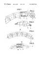
- FIG. 1is a general, partially sectional illustration of a first embodiment of a pull cable system according to the present invention
- FIG. 2is a cross sectional view of the pull cable system of FIG. 1;
- FIG. 3is a cutaway view of the pull cable system of FIG. 1;
- FIG. 4is a general illustration of a second embodiment of a pull cable system according to the present invention.
- FIG. 5is a partially cutaway view of the pull cable system of FIG. 4;
- FIG. 6is a general illustration of a third embodiment of a pull cable system according to the present invention showing first and second type form parts, the first type form part having a cylindrical collar;
- FIGS. 7 to 10shows side views of form-parts having formed therein different configurations of an axial throughbore
- FIG. 11is a general illustration of a frame assembly containing a curved arrangement of a pull cable system according to the present invention.
- FIG. 11.1is a rear section view in a vertical plane of the frame assembly of FIG. 11;
- FIG. 11.2is a front section view in a vertical plane of the frame assembly of FIG. 11;
- FIG. 12is a general illustration of a frame tube accommodating a pull cable system, in diagonal extension, according to the present invention.
- FIG. 12.1is a cutaway side view of the pull cable system of FIG. 12;
- FIG. 12.2is a cutaway top view of the pull cable system of FIG. 12.
- FIG. 13is a cutaway view, in cross section, of an attachment of a pull cable system to a frame assembly.
- FIGS. 1 to 3there are shown general, partially sectional illustrations of a first embodiment of a pull cable system according to the present invention, including a plurality of form-parts 1 joined to one another in-end-to-end relationship and threaded on a flexible support tube C.
- Each of the form-parts 1has one end face to define a support surface 2 of a convex spherical curvature, while the opposite end face is configured as a concave opening 3 in the form of a ball pan being congruent to the support surface 2 .
- the joined form-parts 1fit congruently surface 2 in surface 3 , which allows a narrow disposition of curves with little friction, as the different lengths are compensated by the spherical shape.
- the form-parts 1can be deflected in central direction but can be lined up along the support tube C to exhibit a continuous curved path.
- the form-parts 1are provided interiorly with a bore 4 so that the arrangement of successive form-parts 1 provide a continuous passageway for receiving a pull cable A.
- the bore 4 of each form-part 1has an inside dimension which corresponds to the outside dimension of the support tube C.
- the bores 4 of the form-parts 1may also have different configuration, with FIG. 7 showing a form-part 1 with opposite convex support surfaces 2 , 3 , with FIG. 8 showing a ball-shaped form-part 1 , with FIG. 9 showing a form-part 1 with concave support surface and cylindrical bore 4 , and with FIG. 10 showing a form-part 1 with flat end faces 2 , 3 and cylindrical bore 4 .
- the form-parts 1are so configured that one of the end faces 2 , 3 has a concave configuration and the other one of the end faces has a convex configuration. It is also possible to alternate a first type of form-parts having convex end faces with a second type of form-parts having concave or ring-shaped end faces, whereby the inside dimension of the first type of form-parts corresponds to the cross section of the tube C while the bore 4 of the second type of form-parts has an inside dimension which exceeds the cross section of the tube C.
- the form-part 1may also be provided with a central recess 5 to exhibit a free space. If the pull cable A is drawn, the compensating support casing made from the joined threaded form-parts does not press against the cable A to realize a smooth transmission.
- the form-parts 1may be made of metal, in particular of anodized aluminum, but can also be made of ceramic or plastic material that has advantageously been shaped to the form-parts 1 by injection moulding.
- the individual form-parts 1should be threaded onto a smooth plastic tube to realize a continuous strand, which is of advantage with respect to easy handling and marketing.
- the joined form-parts 1may be additionally covered by a hose (not shown) to realize a stable and bendable unit.
- FIGS. 4 and 5show a further embodiment of a pull cable system which differs from the embodiment of FIGS. 1 to 3 in the configuration of the passageway 4 .
- Each form-part 1has on one end face 3 formed as a pan for receiving the adjacent, approximately ball-shaped end face of an adjoining form-part 1 .
- the form-parts 1are provided with free spaces 5 a, 5 b for enabling a continuous course of the support tube C along a curved path.
- FIG. 6is a general illustration of another embodiment of a pull cable system according to the present invention, including form-parts 1 with cylindrical collar 12 .
- the form-parts 1may be made of glidable material. It is also conceivable to omit the provision of the support tube C altogether, when using form-parts of sufficient length and of glidable material so that the cable A for transmitting tensile forces is supported directly by the throughbore 4 of the form-parts 1 .
- FIGS. 11, 11 . 1 and 11 . 2Another embodiment of the force transmission with little friction is the partly unsupported arrangement of the pull cable between supports fastened to a frame assembly, as shown in FIGS. 11, 11 . 1 and 11 . 2 .
- the pull cable Ais guided over attachable ball or roller bearings of a curve segment 20 of the frame assembly.
- Two types of bearingsmay be used: the roller bearing 23 or the ball bearing 24 . Both show an only small loss of force due to minimized friction.
- Another way of disposing the pull cable with minimized friction valuesmay be achieved by disposing the pull cables A diagonally in a frame tube or assembly 25 which extends between a cable inlet fitting 25 . 1 and a cable outlet fitting 25 . 2 , as shown in FIGS. 12, 12 . 1 and 12 . 2 .
- Thiscan also be achieved by retrofitting, i.e., by arranging one or more (plastic) tube/tubes from the cable inlet 25 . 1 to the cable outlet 25 . 2 and by gluing them to the outlets at the respective end face such that the cable A is easy to be disposed in order to traverse the tube 25 diagonally, so as to leave the end of the tube without friction or contact via the cable outlet 25 . 2 .
- This methodhas the advantage that neither a noisy striking of the cable A against the frame tube 25 nor increased friction values will occur.
- the curve segment 20is further provided with a sliding and support ring 22 positioned between the cable A and the rollers 24 and having a groove for receiving the cable A.
- a cover cap 21 . 2envelops around the cable A and the ring 22 and is attached to the curve segment 20 .
- the ring 22is also formed with a groove for receiving the cable A and has an inside diameter equal to the sum of inner radius of the running surface 24 . 1 of the segment 20 and the diameter of the ball 24 .
Landscapes
- Engineering & Computer Science (AREA)
- General Engineering & Computer Science (AREA)
- Health & Medical Sciences (AREA)
- Oral & Maxillofacial Surgery (AREA)
- Mechanical Engineering (AREA)
- Flexible Shafts (AREA)
- Mechanical Operated Clutches (AREA)
Abstract
Description
The invention relates to a pull cable system of a type having a cable for transmitting a pull force and a housing enclosing the cable for absorbing a pressure force, whereby the housing is comprised of a plurality of form-parts so joined to one another as to form a continuous axial throughbore and to enable an arcuate disposition of the housing.
The so-called Bowden pull wire that basically consists of a coiled steel wire casing and is traversed by a pull cable transmitting pull forces in a flexible manner without deflection rollers, compensating holders and supports is preferably used for operating the brakes or switching the gears of a bike.
The disadvantage of the Bowden pull wire is its coiled steel wire construction. When the wire is disposed in a curve, there are two differently stretched lengths to be compensated by forming slits at the outer radius by means of the resiliently coiled steel wire construction. When the pull cable is actuated, the compensating force can be supported only at the inner radius, which has the effect of pulling the Bowden pull wire into a stretched position. This can be prevented by the pull cable imposing this forced position. The result is a high friction resistance. The stronger the pull cable is being drawn, the larger is the friction resistance, the more ineffective is the force transmission, which presents a major disadvantage with regard to braking operations.
The variation in lengths occurring when bending the pull cable presents such a disadvantage that the Bowden pull wire is hardly suited for precise chain or hub gear shifting.
A narrow disposition of curves is not possible, which requires an unnecessary addition of length of the Bowden pull wire and thus causes higher costs, provides a disadvantageous optical appearance and long paths and thus hardly allows controlled dispositions.
It is an object of the present invention to provide an improved pull cable system in which the friction resistance is minimized and which exhibits a better directional stability, a much narrower and tension-free disposition in curves, a reduction of the contact surfaces of the pull cable by 75% and a removal of sliding restraints, as well as better armoring and sealing against outer influences.
According to the present invention, this object is solved by a pull cable system which includes a cable for transmitting a tensile force, a flexible tube for accommodating the cable, and a casing surrounding the tube for absorbing a pressure force, whereby the housing is composed of a plurality of congruent form-parts so joined to one another as to form a continuous axial passageway which is defined by an inside dimension, with the form-parts being so configured that abutting end faces between successive form-parts have a complementary configuration to thereby enable a disposition of the housing along an arcuate path, wherein the tube is defined by an outside dimension corresponding to the inside dimension of the throughbore.
Preferably, each of the form-parts has opposite end faces, with one of the end faces having a concave configuration and the other one of the end faces having a convex configuration. Thus, in accordance with the present invention, the coiled steel wire casing utilized in a conventional Bowden cable is replaced by joined complementary form-parts which permit transmission of great pressure forces by way of a ball pan configuration of adjoining end faces of successive form-parts.
The above and other objects, features and advantages of the present invention will now be described in more detail with reference to the accompanying drawing in which:
FIG. 1 is a general, partially sectional illustration of a first embodiment of a pull cable system according to the present invention;
FIG. 2 is a cross sectional view of the pull cable system of FIG. 1;
FIG. 3 is a cutaway view of the pull cable system of FIG. 1;
FIG. 4 is a general illustration of a second embodiment of a pull cable system according to the present invention;
FIG. 5 is a partially cutaway view of the pull cable system of FIG. 4;
FIG. 6 is a general illustration of a third embodiment of a pull cable system according to the present invention showing first and second type form parts, the first type form part having a cylindrical collar;
FIGS. 7 to10 shows side views of form-parts having formed therein different configurations of an axial throughbore;
FIG. 11 is a general illustration of a frame assembly containing a curved arrangement of a pull cable system according to the present invention;
FIG. 11.1 is a rear section view in a vertical plane of the frame assembly of FIG. 11;
FIG. 11.2 is a front section view in a vertical plane of the frame assembly of FIG. 11;
FIG. 12 is a general illustration of a frame tube accommodating a pull cable system, in diagonal extension, according to the present invention;
FIG. 12.1 is a cutaway side view of the pull cable system of FIG. 12;
FIG. 12.2 is a cutaway top view of the pull cable system of FIG. 12; and
FIG. 13 is a cutaway view, in cross section, of an attachment of a pull cable system to a frame assembly.
Turning now to the drawing, and in particular to FIGS. 1 to3, there are shown general, partially sectional illustrations of a first embodiment of a pull cable system according to the present invention, including a plurality of form-parts 1 joined to one another in-end-to-end relationship and threaded on a flexible support tube C. Each of the form-parts 1 has one end face to define asupport surface 2 of a convex spherical curvature, while the opposite end face is configured as aconcave opening 3 in the form of a ball pan being congruent to thesupport surface 2. The joined form-parts 1 fit congruentlysurface 2 insurface 3, which allows a narrow disposition of curves with little friction, as the different lengths are compensated by the spherical shape. Thus, the form-parts 1 can be deflected in central direction but can be lined up along the support tube C to exhibit a continuous curved path.
The form-parts 1 are provided interiorly with abore 4 so that the arrangement of successive form-parts 1 provide a continuous passageway for receiving a pull cable A. Thebore 4 of each form-part 1 has an inside dimension which corresponds to the outside dimension of the support tube C. As shown by way of example in FIGS. 7 to10, thebores 4 of the form-parts 1 may also have different configuration, with FIG. 7 showing a form-part 1 with oppositeconvex support surfaces part 1, with FIG. 9 showing a form-part 1 with concave support surface andcylindrical bore 4, and with FIG. 10 showing a form-part 1 withflat end faces cylindrical bore 4.
Suitably, the form-parts 1 are so configured that one of theend faces bore 4 of the second type of form-parts has an inside dimension which exceeds the cross section of the tube C.
As shown in FIG. 1, the form-part 1 may also be provided with acentral recess 5 to exhibit a free space. If the pull cable A is drawn, the compensating support casing made from the joined threaded form-parts does not press against the cable A to realize a smooth transmission. The form-parts 1 may be made of metal, in particular of anodized aluminum, but can also be made of ceramic or plastic material that has advantageously been shaped to the form-parts 1 by injection moulding.
In order to improve their handling, the individual form-parts 1 should be threaded onto a smooth plastic tube to realize a continuous strand, which is of advantage with respect to easy handling and marketing. Also, the joined form-parts 1 may be additionally covered by a hose (not shown) to realize a stable and bendable unit.
FIGS. 4 and 5 show a further embodiment of a pull cable system which differs from the embodiment of FIGS. 1 to3 in the configuration of thepassageway 4. Each form-part 1 has on oneend face 3 formed as a pan for receiving the adjacent, approximately ball-shaped end face of an adjoining form-part 1. The form-parts 1 are provided withfree spaces
FIG. 6 is a general illustration of another embodiment of a pull cable system according to the present invention, including form-parts 1 withcylindrical collar 12.
The form-parts 1 may be made of glidable material. It is also conceivable to omit the provision of the support tube C altogether, when using form-parts of sufficient length and of glidable material so that the cable A for transmitting tensile forces is supported directly by thethroughbore 4 of the form-parts 1.
Another embodiment of the force transmission with little friction is the partly unsupported arrangement of the pull cable between supports fastened to a frame assembly, as shown in FIGS. 11,11.1 and11.2. For the deflection of force (disposition of curves), the pull cable A is guided over attachable ball or roller bearings of acurve segment 20 of the frame assembly. Two types of bearings may be used: the roller bearing23 or the ball bearing24. Both show an only small loss of force due to minimized friction.
Another way of disposing the pull cable with minimized friction values may be achieved by disposing the pull cables A diagonally in a frame tube orassembly 25 which extends between a cable inlet fitting25.1 and a cable outlet fitting25.2, as shown in FIGS. 12,12.1 and12.2. This can also be achieved by retrofitting, i.e., by arranging one or more (plastic) tube/tubes from the cable inlet25.1 to the cable outlet25.2 and by gluing them to the outlets at the respective end face such that the cable A is easy to be disposed in order to traverse thetube 25 diagonally, so as to leave the end of the tube without friction or contact via the cable outlet25.2. Thus, there will not be any contact with the tube. This method has the advantage that neither a noisy striking of the cable A against theframe tube 25 nor increased friction values will occur.
As shown in FIG. 13, thecurve segment 20 is further provided with a sliding andsupport ring 22 positioned between the cable A and therollers 24 and having a groove for receiving the cable A. A cover cap21.2 envelops around the cable A and thering 22 and is attached to thecurve segment 20. Thering 22 is also formed with a groove for receiving the cable A and has an inside diameter equal to the sum of inner radius of the running surface24.1 of thesegment 20 and the diameter of theball 24.
Claims (4)
1. A flexible tensile force transmitting cable system, comprising:
a cable for transmitting a tensile force;
a flexible tube receiving said cable for axial movement and having an outside dimension; and
a casing surrounding said tube, said casing including a plurality of form-parts joined to one another to form a continuous axial passageway defined by an inside dimension of varying diameters, said form-parts comprising a first set of form-parts alternately joined to a second set of form-parts, said first set of form-parts having opposite convex end faces, said second set of form-parts having opposite end faces, each having one of a concave shape and an annular shape, each of said first set of form-parts having an inside dimension corresponding to a cross section of said tube, said passageway in said second set of said form-parts having an inside dimension exceeding the cross section of said tube, said form-parts having abutting end faces between adjacent form-parts with complementary configurations enabling dispositions of said casing along accurate paths, each dispositions of said casing along arcuate paths, each of said form-parts having an interior recess forming a section of said axial passageway with an interior diameter exceeding said outside dimension of said tube.
2. A flexible tensile force transmitting cable system, comprising:
a cable for transmitting a tensile force;
a flexible tube for receiving said cable for axial movement of said cable and having an outside diameter; and
a casing surrounding said tube, said casing including a plurality of form-parts joined to one another to form a continuous axial passageway defined by an inside dimension of varying diameters, said form-parts including a first set of form-parts alternately joined to a second set of form-parts, said first set of form-parts having opposite convex end faces, said second set of form-parts having opposite end faces, each having one of a concave shape and an annular shape, each of said first set a form-parts having a circumferential cylindrical collar centrally located thereon, said form parts having abutting end faces between adjacent form-parts with complementary configurations enabling dispositions of said casing along arcuate paths, each of said form-parts having an interior recess forming a section of said axial passageway with an interior diameter exceeding said outside dimension of said tube.
3. A flexible tensile force transmitting cable system, comprising:
a cable for transmitting a tensile force;
a flexible tube for accommodating the cable; and
a casing surrounding said tube for absorbing a pressure force, said casing including a plurality of form-parts joined to one another to form a continuous axial passageway defined by an inside dimension of varying diameters, said form-parts having abutting end faces between successive form-parts with complementary configurations enabling dispositions of said casing along an arcuate path, said form-parts comprising first and second sets of form parts, said tube having an outside dimension corresponding to an inside dimension of the passageway, each of said form parts having an interior recess forming a section of said axial passageway with an interior dimension with a diameter exceeding that of the tube for creating a space for compensatory movement of said tube within said axial passageway when the cable therein transmits a tensile force, each of said first set of form-parts having an inside dimension corresponding to a cross section of said tube, with said axial passageway in said second set of form-parts having an inside dimension exceeding the cross-section of said tube.
4. A flexible tensile force transmitting cable system, comprising:
a cable for transmitting a tensile force, said cable extending diagonally through a frame assembly;
fittings securing said cable system at opposite ends of said frame assembly;
a flexible tube for accommodating the cable; and
a casing surrounding said tube for absorbing a pressure force, said casing including a plurality of form-parts joined to one another to form a continuous axial passageway defined by an inside dimension of varying diameters, said form-parts having abutting end faces between successive form-parts with complementary configurations enabling dispositions of said casing along an arcuate path, said tube having an outside dimension corresponding to an inside dimension of the passageway, each of said form parts having an interior recess forming a section of said axial passageway with an interior dimension with a diameter exceeding that of the tube for creating a space for compensatory movement of said tube within said axial passageway when the cable therein transmits a tensile force.
Priority Applications (1)
| Application Number | Priority Date | Filing Date | Title |
|---|---|---|---|
| US09/809,020US6606921B2 (en) | 1995-09-19 | 2001-03-16 | Pull cable system |
Applications Claiming Priority (3)
| Application Number | Priority Date | Filing Date | Title |
|---|---|---|---|
| DE19534643ADE19534643C2 (en) | 1995-03-23 | 1995-09-19 | Flexible and smooth power transmission |
| DE19534643 | 1995-09-19 | ||
| PCT/DE1996/001801WO1997011283A2 (en) | 1995-09-19 | 1996-09-19 | Push-pull transmission system made from mouldings |
Related Parent Applications (1)
| Application Number | Title | Priority Date | Filing Date |
|---|---|---|---|
| PCT/DE1996/001801A-371-Of-InternationalWO1997011283A2 (en) | 1995-09-19 | 1996-09-19 | Push-pull transmission system made from mouldings |
Related Child Applications (1)
| Application Number | Title | Priority Date | Filing Date |
|---|---|---|---|
| US09/809,020ContinuationUS6606921B2 (en) | 1995-09-19 | 2001-03-16 | Pull cable system |
Publications (1)
| Publication Number | Publication Date |
|---|---|
| US6250175B1true US6250175B1 (en) | 2001-06-26 |
Family
ID=7772515
Family Applications (2)
| Application Number | Title | Priority Date | Filing Date |
|---|---|---|---|
| US08/973,232Expired - LifetimeUS6250175B1 (en) | 1995-09-19 | 1996-09-19 | Pull cable system |
| US09/809,020Expired - LifetimeUS6606921B2 (en) | 1995-09-19 | 2001-03-16 | Pull cable system |
Family Applications After (1)
| Application Number | Title | Priority Date | Filing Date |
|---|---|---|---|
| US09/809,020Expired - LifetimeUS6606921B2 (en) | 1995-09-19 | 2001-03-16 | Pull cable system |
Country Status (3)
| Country | Link |
|---|---|
| US (2) | US6250175B1 (en) |
| EP (1) | EP0832364B1 (en) |
| WO (1) | WO1997011283A2 (en) |
Cited By (39)
| Publication number | Priority date | Publication date | Assignee | Title |
|---|---|---|---|---|
| US20030086240A1 (en)* | 2001-11-08 | 2003-05-08 | Jobs Steven P | Computer controlled display device |
| US6725692B2 (en) | 2002-09-26 | 2004-04-27 | Weinraub Enterprises, Inc. | Firearm lock assembly |
| US20040218352A1 (en)* | 2001-11-08 | 2004-11-04 | Hillman Michael D. | Computer controlled display device |
| US20040228080A1 (en)* | 2001-11-08 | 2004-11-18 | Hillman Michael D. | Computer controlled display device |
| US20040233623A1 (en)* | 2001-11-08 | 2004-11-25 | Hillman Michael D. | Computer controlled display device |
| US20040257755A1 (en)* | 2001-11-08 | 2004-12-23 | Hillman Michael D. | Computer controlled display device |
| US20050029059A1 (en)* | 2003-04-25 | 2005-02-10 | Errol Drew | Method and apparatus for restraining cable curvature |
| US20050088812A1 (en)* | 2001-11-08 | 2005-04-28 | Hillman Michael D. | Computer controlled display device |
| US20050166701A1 (en)* | 2002-06-22 | 2005-08-04 | Bayerische Motoren Werke Ag | Bowden cable with a curved guide part |
| US20060176655A1 (en)* | 2001-11-08 | 2006-08-10 | Hillman Michael D | Computer controlled display device |
| US20070131567A1 (en)* | 2005-12-09 | 2007-06-14 | Park Chan S | High temperature and pressure sensor |
| US20070201197A1 (en)* | 2001-11-08 | 2007-08-30 | Hillman Michael D | Computer controlled display device |
| DE202008004839U1 (en) | 2008-04-03 | 2008-07-03 | Wen, Yuan-Hung, Hemei | The construction to protect the pull rope |
| DE202008004838U1 (en) | 2008-04-03 | 2008-07-10 | Wen, Yuan-Hung, Hemei | The construction of the protective tube of the cable |
| US20080243064A1 (en)* | 2007-02-15 | 2008-10-02 | Hansen Medical, Inc. | Support structure for robotic medical instrument |
| US20090095114A1 (en)* | 2007-10-15 | 2009-04-16 | Ridgway Jason R | Steering column assembly having a rotating drive cable device |
| WO2009111923A1 (en)* | 2008-03-11 | 2009-09-17 | Wen Yuan-Hung | Cable protective tube structure |
| US20090235774A1 (en)* | 2008-03-19 | 2009-09-24 | Wen Yuan-Hung | Casing system for protecting a cable |
| US20090235773A1 (en)* | 2008-03-19 | 2009-09-24 | Wen Yuan-Hung | Casing system for protecting a cable |
| EP1534111A4 (en)* | 2002-06-11 | 2010-01-20 | Handy Shower Ltd | Bimodal flexible-rigid hose |
| US20100025976A1 (en)* | 2006-11-30 | 2010-02-04 | Murtha Philip G | Occupant restraint |
| US20110031359A1 (en)* | 2009-08-05 | 2011-02-10 | Ningbo Weifeng Image Equipment Group Co., Ltd. | Winding tripod |
| US20110034257A1 (en)* | 2008-03-11 | 2011-02-10 | Wen Yuan-Hung | Protective sheath for cable |
| US20110051587A1 (en)* | 2009-08-25 | 2011-03-03 | Jinn-Kang Wang | Structure For Optical Pickup Head |
| DE102010061277B3 (en)* | 2010-12-15 | 2012-02-23 | Yuan-Hung WEN | Protective cover for cable, comprises multiple piping components having external metal pipe that is provided with head section, body, attachment section and end section, where attachment section has inner diameter |
| CN101943207B (en)* | 2009-07-08 | 2012-03-14 | 温芫鋐 | Conduit lubrication transfer structure |
| EP2458234A2 (en) | 2010-11-30 | 2012-05-30 | Yuan-Hung Wen | Cable sheath |
| EP2492524A1 (en) | 2011-02-22 | 2012-08-29 | Yuan-Hung Wen | Brake cable sheath for bicycle |
| DE102011001580A1 (en) | 2011-03-25 | 2012-09-27 | Yuan-Hung WEN | Protective cover for bicycle cable, has fastening holes that are connected with cut opening through opening portions, so that wire is inserted into cut opening in radial direction through mounting hole |
| CN102905631A (en)* | 2010-05-31 | 2013-01-30 | 奥林巴斯株式会社 | Driving force transmission mechanism and manipulator system |
| TWI402447B (en)* | 2012-03-13 | 2013-07-21 | Jian Hong Chen | Fixation device for brake oil tube |
| US8497427B2 (en) | 2010-12-28 | 2013-07-30 | Yuan-Hung WEN | Segmented cable sheath with inner sleeves |
| US9079065B2 (en) | 2012-06-15 | 2015-07-14 | Black Diamond Equipment Ltd. | Camming device |
| US9302154B2 (en) | 2012-06-15 | 2016-04-05 | Black Diamond Equipment, Ltd. | Camming device stem |
| US9579955B2 (en)* | 2014-08-26 | 2017-02-28 | Magna Mirros Of America, Inc. | Rear slider window assembly with heated movable window |
| US20170149220A1 (en)* | 2015-11-19 | 2017-05-25 | Winkle Industries, Inc. | Protective component for power cable of an industrial electro-magnetic lifting device |
| US10524313B2 (en) | 2017-02-09 | 2019-12-31 | Magna Mirrors Of America, Inc. | Rear slider window assembly with laminated heating element |
| US11079807B1 (en)* | 2017-08-03 | 2021-08-03 | Apple Inc. | Friction roller hinge for electronic devices and method for making roller and spacer elements |
| US12054035B2 (en) | 2019-08-08 | 2024-08-06 | Magna Mirrors Of America, Inc. | Vehicular rear window assembly with continuous heater trace |
Families Citing this family (26)
| Publication number | Priority date | Publication date | Assignee | Title |
|---|---|---|---|---|
| GB2307532B (en)* | 1995-11-21 | 1999-11-03 | Christopher John Hooker | Drive assembly |
| DK173190B1 (en) | 1998-04-08 | 2000-03-13 | Velux Ind As | Method and apparatus for pressure and / or traction transmission |
| US7182731B2 (en)* | 2002-01-23 | 2007-02-27 | Genesee Biomedical, Inc. | Support arm for cardiac surgery |
| US7294078B2 (en)* | 2002-05-21 | 2007-11-13 | Delphi Technologies, Inc. | Over-molded beaded cable for driving applications |
| US20060179966A1 (en)* | 2005-02-03 | 2006-08-17 | Kuo Yung-Pin | Flexible sheath for cables |
| US7634874B2 (en)* | 2006-04-18 | 2009-12-22 | Luco-Ed Enterprises Llc | Collapsible structural members |
| DE202008011658U1 (en)* | 2008-09-02 | 2010-01-28 | Canyon Bicycles Gmbh | Bicycle frame tube |
| TWM371687U (en)* | 2009-06-24 | 2010-01-01 | Chia Cherne Industry Co Ltd | Multinodal structure of protective sheath for operation control filament of bicycle |
| US20130318896A1 (en)* | 2012-06-04 | 2013-12-05 | Donald Scott Rogers | Pre-Tensioned Discrete Element Support System |
| US10828171B2 (en)* | 2013-07-18 | 2020-11-10 | The University Of Toledo | Expandable inter-vertebral cage and method of installing same |
| CN106029039B (en) | 2013-12-16 | 2018-03-27 | 麻省理工学院 | The optimal design of lower limb exoskeleton or KAFO |
| US9145186B2 (en)* | 2014-04-29 | 2015-09-29 | Tektro Technology Corporation | Quick-release device of bicycle brake cable |
| FR3038857B1 (en)* | 2015-07-15 | 2018-03-09 | Airbus Operations | DEVICE FOR PROTECTING GAS DIFFUSION WELDING |
| US10190334B2 (en) | 2015-11-03 | 2019-01-29 | Schlage Lock Company Llc | Adjustable length cable |
| EP3544664B1 (en) | 2016-11-22 | 2021-09-22 | Boston Scientific Scimed, Inc. | Medical delivery system |
| CN110430843B (en) | 2017-03-14 | 2022-06-07 | 波士顿科学国际有限公司 | Medical device shaft including a liner |
| US10869762B2 (en) | 2017-03-14 | 2020-12-22 | Boston Scientific Scimed, Inc. | Medical device with inner assembly |
| JP6884884B2 (en) | 2017-05-03 | 2021-06-09 | ボストン サイエンティフィック サイムド,インコーポレイテッドBoston Scientific Scimed,Inc. | Medical device with sealing assembly |
| JP7114738B2 (en) | 2018-04-26 | 2022-08-08 | ボストン サイエンティフィック サイムド,インコーポレイテッド | Medical device with connecting member |
| CN112334097B (en) | 2018-04-26 | 2025-06-13 | 波士顿科学国际有限公司 | Medical device with telescopic sealing assembly |
| WO2019210169A1 (en) | 2018-04-26 | 2019-10-31 | Boston Scientific Scimed, Inc. | Motorized telescoping medical device delivery system |
| US11723767B2 (en) | 2019-08-15 | 2023-08-15 | Boston Scientific Scimed, Inc. | Medical device including attachable tip member |
| US12016777B2 (en) | 2021-01-26 | 2024-06-25 | Boston Scientific Scimed, Inc. | Medical device including attachable components |
| US12396852B2 (en) | 2021-01-26 | 2025-08-26 | Boston Scientific Scimed, Inc. | Medical device including attachable components |
| JP7577627B2 (en) | 2021-07-26 | 2024-11-05 | 本田技研工業株式会社 | Casing |
| NL2030151B1 (en) | 2021-12-16 | 2023-06-28 | Lentolin B V | Guide for a bendable connecting means, such as a cable or a wiring |
Citations (21)
| Publication number | Priority date | Publication date | Assignee | Title |
|---|---|---|---|---|
| FR358269A (en) | 1905-07-20 | 1906-02-07 | Richard Buettner | Flexible device for remote pressure transmission |
| FR647162A (en) | 1927-06-02 | 1928-11-21 | Improvements to force transmission devices by sheathed cables | |
| FR674990A (en) | 1929-03-11 | 1930-02-04 | Bendix Brake Co | Enhancements to flexible devices for power transmission |
| US1746719A (en) | 1925-08-19 | 1930-02-11 | Steeldraulic Brake Corp | Flexible conduit |
| US1772453A (en) | 1928-03-23 | 1930-08-12 | Midland Steel Prod Co | Flexible conduit |
| US1916896A (en)* | 1928-03-21 | 1933-07-04 | Midland Steel Prod Co | Flexible conduit |
| US1939766A (en)* | 1930-11-18 | 1933-12-19 | Corset Lucien Alfred Maurice | Transmission device |
| US2441719A (en)* | 1945-08-21 | 1948-05-18 | Southwest Products Co | Mechanical, lineal, rotary, flexible, push-pull transmission device |
| US3096962A (en)* | 1960-02-04 | 1963-07-09 | Meijs Pieter Johannes | Locking device for a measuring apparatus or the like |
| US3298243A (en)* | 1964-06-26 | 1967-01-17 | Ulrich M Geissler | Cables and load bearing supports therefor |
| US3494214A (en)* | 1967-09-12 | 1970-02-10 | Emil Egli | Link chain for transmitting a mechanical load |
| US3546961A (en)* | 1967-12-22 | 1970-12-15 | Gen Electric | Variable flexibility tether |
| US3625077A (en)* | 1968-08-22 | 1971-12-07 | Commissariat Energie Atomique | Transfer rods |
| US3858578A (en)* | 1974-01-21 | 1975-01-07 | Pravel Wilson & Matthews | Surgical retaining device |
| US3927899A (en)* | 1974-03-22 | 1975-12-23 | Trw Inc | Vehicle steering apparatus |
| US4102219A (en)* | 1977-08-19 | 1978-07-25 | Mtd Products Inc. | Fair-leads for a control wire |
| US4356737A (en)* | 1979-02-14 | 1982-11-02 | Max Kammerer Gmbh | Device for the rotating actuation of linearly actuated control elements |
| US4380178A (en)* | 1980-07-21 | 1983-04-19 | Teleflex Incorporated | Remote control assembly (swivel insert) |
| US5091141A (en) | 1989-05-23 | 1992-02-25 | Framatome | Device for inserting and positioning a tool inside a heat exchanger and use of this device |
| US5174164A (en)* | 1991-09-16 | 1992-12-29 | Westinghouse Electric Corp. | Flexible cable |
| US5448926A (en)* | 1993-11-03 | 1995-09-12 | Teleflex Incorporated | Remote control assembly with vibration dampener |
Family Cites Families (12)
| Publication number | Priority date | Publication date | Assignee | Title |
|---|---|---|---|---|
| DE225753C (en) | ||||
| US870429A (en)* | 1907-04-27 | 1907-11-05 | Frank G Grimler | Sectional stand. |
| US2510198A (en)* | 1947-10-17 | 1950-06-06 | Earl B Tesmer | Flexible positioner |
| US2869377A (en)* | 1954-09-13 | 1959-01-20 | Pieterse Marius Cornelis | Devices for the transmission of movements |
| GB1194381A (en)* | 1967-04-14 | 1970-06-10 | Polar Hydraulics Ltd | Improvements in a Supporting Stand for Instruments |
| US4225258A (en)* | 1979-04-13 | 1980-09-30 | Thompson William E | Pivot mechanism and method of manufacturing same |
| DE3333543C3 (en)* | 1983-09-16 | 1995-02-09 | Ernst Klein | Self-supporting energy conductor |
| ATE93068T1 (en)* | 1988-12-05 | 1993-08-15 | Kupferdraht Isolierwerk Ag | SELF-SUPPORTING OPTICAL CABLE. |
| US4949927A (en)* | 1989-10-17 | 1990-08-21 | John Madocks | Articulable column |
| GB9023394D0 (en)* | 1990-10-26 | 1990-12-05 | Gore W L & Ass Uk | Segmented flexible housing |
| US5159849A (en)* | 1991-10-07 | 1992-11-03 | The Babcock & Wilcox Company | Serpentine tube inspection positioning spine |
| JP2912890B2 (en)* | 1996-09-13 | 1999-06-28 | 日東工業株式会社 | Protective plate for underground objects |
- 1996
- 1996-09-19EPEP96944562Apatent/EP0832364B1/ennot_activeExpired - Lifetime
- 1996-09-19USUS08/973,232patent/US6250175B1/ennot_activeExpired - Lifetime
- 1996-09-19WOPCT/DE1996/001801patent/WO1997011283A2/enactiveIP Right Grant
- 2001
- 2001-03-16USUS09/809,020patent/US6606921B2/ennot_activeExpired - Lifetime
Patent Citations (21)
| Publication number | Priority date | Publication date | Assignee | Title |
|---|---|---|---|---|
| FR358269A (en) | 1905-07-20 | 1906-02-07 | Richard Buettner | Flexible device for remote pressure transmission |
| US1746719A (en) | 1925-08-19 | 1930-02-11 | Steeldraulic Brake Corp | Flexible conduit |
| FR647162A (en) | 1927-06-02 | 1928-11-21 | Improvements to force transmission devices by sheathed cables | |
| US1916896A (en)* | 1928-03-21 | 1933-07-04 | Midland Steel Prod Co | Flexible conduit |
| US1772453A (en) | 1928-03-23 | 1930-08-12 | Midland Steel Prod Co | Flexible conduit |
| FR674990A (en) | 1929-03-11 | 1930-02-04 | Bendix Brake Co | Enhancements to flexible devices for power transmission |
| US1939766A (en)* | 1930-11-18 | 1933-12-19 | Corset Lucien Alfred Maurice | Transmission device |
| US2441719A (en)* | 1945-08-21 | 1948-05-18 | Southwest Products Co | Mechanical, lineal, rotary, flexible, push-pull transmission device |
| US3096962A (en)* | 1960-02-04 | 1963-07-09 | Meijs Pieter Johannes | Locking device for a measuring apparatus or the like |
| US3298243A (en)* | 1964-06-26 | 1967-01-17 | Ulrich M Geissler | Cables and load bearing supports therefor |
| US3494214A (en)* | 1967-09-12 | 1970-02-10 | Emil Egli | Link chain for transmitting a mechanical load |
| US3546961A (en)* | 1967-12-22 | 1970-12-15 | Gen Electric | Variable flexibility tether |
| US3625077A (en)* | 1968-08-22 | 1971-12-07 | Commissariat Energie Atomique | Transfer rods |
| US3858578A (en)* | 1974-01-21 | 1975-01-07 | Pravel Wilson & Matthews | Surgical retaining device |
| US3927899A (en)* | 1974-03-22 | 1975-12-23 | Trw Inc | Vehicle steering apparatus |
| US4102219A (en)* | 1977-08-19 | 1978-07-25 | Mtd Products Inc. | Fair-leads for a control wire |
| US4356737A (en)* | 1979-02-14 | 1982-11-02 | Max Kammerer Gmbh | Device for the rotating actuation of linearly actuated control elements |
| US4380178A (en)* | 1980-07-21 | 1983-04-19 | Teleflex Incorporated | Remote control assembly (swivel insert) |
| US5091141A (en) | 1989-05-23 | 1992-02-25 | Framatome | Device for inserting and positioning a tool inside a heat exchanger and use of this device |
| US5174164A (en)* | 1991-09-16 | 1992-12-29 | Westinghouse Electric Corp. | Flexible cable |
| US5448926A (en)* | 1993-11-03 | 1995-09-12 | Teleflex Incorporated | Remote control assembly with vibration dampener |
Cited By (66)
| Publication number | Priority date | Publication date | Assignee | Title |
|---|---|---|---|---|
| US7035092B2 (en) | 2001-11-08 | 2006-04-25 | Apple Computer, Inc. | Computer controlled display device |
| US20050088812A1 (en)* | 2001-11-08 | 2005-04-28 | Hillman Michael D. | Computer controlled display device |
| CN100439789C (en)* | 2001-11-08 | 2008-12-03 | 苹果公司 | computer-controlled display device |
| US7145768B2 (en) | 2001-11-08 | 2006-12-05 | Apple Computer, Inc. | Computer controlled display device |
| US20040218352A1 (en)* | 2001-11-08 | 2004-11-04 | Hillman Michael D. | Computer controlled display device |
| US6819550B2 (en) | 2001-11-08 | 2004-11-16 | Apple Computer, Inc. | Computer controlled display device |
| US20040228080A1 (en)* | 2001-11-08 | 2004-11-18 | Hillman Michael D. | Computer controlled display device |
| US20040233623A1 (en)* | 2001-11-08 | 2004-11-25 | Hillman Michael D. | Computer controlled display device |
| US20040257755A1 (en)* | 2001-11-08 | 2004-12-23 | Hillman Michael D. | Computer controlled display device |
| US7773371B2 (en) | 2001-11-08 | 2010-08-10 | Apple Inc. | Computer controlled display device |
| US7349203B2 (en) | 2001-11-08 | 2008-03-25 | Apple Inc. | Computer controlled display device |
| US20070014084A1 (en)* | 2001-11-08 | 2007-01-18 | Jobs Steven P | Computer controlled display device |
| US20050088814A1 (en)* | 2001-11-08 | 2005-04-28 | Jobs Steven P. | Computer controlled display device |
| US20070201197A1 (en)* | 2001-11-08 | 2007-08-30 | Hillman Michael D | Computer controlled display device |
| US7218510B2 (en) | 2001-11-08 | 2007-05-15 | Apple Computer, Inc. | Computer controlled display device |
| US20030086240A1 (en)* | 2001-11-08 | 2003-05-08 | Jobs Steven P | Computer controlled display device |
| US7136280B2 (en) | 2001-11-08 | 2006-11-14 | Apple Computer, Inc. | Computer controlled display device |
| US20060176655A1 (en)* | 2001-11-08 | 2006-08-10 | Hillman Michael D | Computer controlled display device |
| US7046509B2 (en) | 2001-11-08 | 2006-05-16 | Apple Computer, Inc. | Computer controlled display device |
| US7142415B2 (en) | 2001-11-08 | 2006-11-28 | Apple Computer, Inc. | Computer controlled display device |
| EP1534111A4 (en)* | 2002-06-11 | 2010-01-20 | Handy Shower Ltd | Bimodal flexible-rigid hose |
| US7201081B2 (en)* | 2002-06-22 | 2007-04-10 | Bayerische Motoren Werke Aktiengesellschaft | Bowden cable with a curved guide part |
| US20050166701A1 (en)* | 2002-06-22 | 2005-08-04 | Bayerische Motoren Werke Ag | Bowden cable with a curved guide part |
| US6725692B2 (en) | 2002-09-26 | 2004-04-27 | Weinraub Enterprises, Inc. | Firearm lock assembly |
| US6810698B2 (en)* | 2002-09-26 | 2004-11-02 | Weinraub Enterprises, Inc. | Firearm lock assembly |
| US20040194515A1 (en)* | 2002-09-26 | 2004-10-07 | Weinraub Adam S. | Firearm lock assembly |
| US7055656B2 (en)* | 2003-04-25 | 2006-06-06 | Delta Cycle Corporation | Apparatus for restraining cable curvature |
| WO2004096628A3 (en)* | 2003-04-25 | 2005-04-21 | Errol Drew | A method and apparatus for restraining cable curvature |
| US20050029059A1 (en)* | 2003-04-25 | 2005-02-10 | Errol Drew | Method and apparatus for restraining cable curvature |
| US20070131567A1 (en)* | 2005-12-09 | 2007-06-14 | Park Chan S | High temperature and pressure sensor |
| US20100025976A1 (en)* | 2006-11-30 | 2010-02-04 | Murtha Philip G | Occupant restraint |
| US20080262513A1 (en)* | 2007-02-15 | 2008-10-23 | Hansen Medical, Inc. | Instrument driver having independently rotatable carriages |
| US20080262480A1 (en)* | 2007-02-15 | 2008-10-23 | Stahler Gregory J | Instrument assembly for robotic instrument system |
| US20080249536A1 (en)* | 2007-02-15 | 2008-10-09 | Hansen Medical, Inc. | Interface assembly for controlling orientation of robotically controlled medical instrument |
| US20080243064A1 (en)* | 2007-02-15 | 2008-10-02 | Hansen Medical, Inc. | Support structure for robotic medical instrument |
| US20090095114A1 (en)* | 2007-10-15 | 2009-04-16 | Ridgway Jason R | Steering column assembly having a rotating drive cable device |
| WO2009111923A1 (en)* | 2008-03-11 | 2009-09-17 | Wen Yuan-Hung | Cable protective tube structure |
| CN101532533B (en)* | 2008-03-11 | 2011-06-01 | 温芫鋐 | Structure of wire protection tube |
| US20110034257A1 (en)* | 2008-03-11 | 2011-02-10 | Wen Yuan-Hung | Protective sheath for cable |
| DE112008003769T5 (en) | 2008-03-11 | 2011-11-17 | Yuan-Hung WEN | A cable sheath to protect a cable |
| CN101532532B (en)* | 2008-03-11 | 2011-05-18 | 温芫鋐 | Structure of wire protection tube |
| US20090235774A1 (en)* | 2008-03-19 | 2009-09-24 | Wen Yuan-Hung | Casing system for protecting a cable |
| US20090235773A1 (en)* | 2008-03-19 | 2009-09-24 | Wen Yuan-Hung | Casing system for protecting a cable |
| DE202008004838U1 (en) | 2008-04-03 | 2008-07-10 | Wen, Yuan-Hung, Hemei | The construction of the protective tube of the cable |
| DE202008004839U1 (en) | 2008-04-03 | 2008-07-03 | Wen, Yuan-Hung, Hemei | The construction to protect the pull rope |
| CN101943207B (en)* | 2009-07-08 | 2012-03-14 | 温芫鋐 | Conduit lubrication transfer structure |
| US20110031359A1 (en)* | 2009-08-05 | 2011-02-10 | Ningbo Weifeng Image Equipment Group Co., Ltd. | Winding tripod |
| US20110051587A1 (en)* | 2009-08-25 | 2011-03-03 | Jinn-Kang Wang | Structure For Optical Pickup Head |
| CN102905631A (en)* | 2010-05-31 | 2013-01-30 | 奥林巴斯株式会社 | Driving force transmission mechanism and manipulator system |
| CN102905631B (en)* | 2010-05-31 | 2015-09-09 | 奥林巴斯株式会社 | Driving force transmission mechanism and arm-and-hand system |
| EP2458234A2 (en) | 2010-11-30 | 2012-05-30 | Yuan-Hung Wen | Cable sheath |
| EP2458234A3 (en)* | 2010-11-30 | 2012-11-14 | Yuan-Hung Wen | Cable sheath |
| DE102010061277B3 (en)* | 2010-12-15 | 2012-02-23 | Yuan-Hung WEN | Protective cover for cable, comprises multiple piping components having external metal pipe that is provided with head section, body, attachment section and end section, where attachment section has inner diameter |
| US8497427B2 (en) | 2010-12-28 | 2013-07-30 | Yuan-Hung WEN | Segmented cable sheath with inner sleeves |
| EP2492524A1 (en) | 2011-02-22 | 2012-08-29 | Yuan-Hung Wen | Brake cable sheath for bicycle |
| DE102011001580A1 (en) | 2011-03-25 | 2012-09-27 | Yuan-Hung WEN | Protective cover for bicycle cable, has fastening holes that are connected with cut opening through opening portions, so that wire is inserted into cut opening in radial direction through mounting hole |
| DE102011001580B4 (en)* | 2011-03-25 | 2013-05-08 | Yuan-Hung WEN | Protective cover for bicycle cable and brake handle assembly with ebendieser protective cover |
| TWI402447B (en)* | 2012-03-13 | 2013-07-21 | Jian Hong Chen | Fixation device for brake oil tube |
| US9079065B2 (en) | 2012-06-15 | 2015-07-14 | Black Diamond Equipment Ltd. | Camming device |
| US9302154B2 (en) | 2012-06-15 | 2016-04-05 | Black Diamond Equipment, Ltd. | Camming device stem |
| US9579955B2 (en)* | 2014-08-26 | 2017-02-28 | Magna Mirros Of America, Inc. | Rear slider window assembly with heated movable window |
| US20170149220A1 (en)* | 2015-11-19 | 2017-05-25 | Winkle Industries, Inc. | Protective component for power cable of an industrial electro-magnetic lifting device |
| US10033171B2 (en)* | 2015-11-19 | 2018-07-24 | Winkle Industries, Inc. | Protective component for power cable of an industrial electro-magnetic lifting device |
| US10524313B2 (en) | 2017-02-09 | 2019-12-31 | Magna Mirrors Of America, Inc. | Rear slider window assembly with laminated heating element |
| US11079807B1 (en)* | 2017-08-03 | 2021-08-03 | Apple Inc. | Friction roller hinge for electronic devices and method for making roller and spacer elements |
| US12054035B2 (en) | 2019-08-08 | 2024-08-06 | Magna Mirrors Of America, Inc. | Vehicular rear window assembly with continuous heater trace |
Also Published As
| Publication number | Publication date |
|---|---|
| WO1997011283A2 (en) | 1997-03-27 |
| EP0832364A2 (en) | 1998-04-01 |
| US6606921B2 (en) | 2003-08-19 |
| US20010025542A1 (en) | 2001-10-04 |
| EP0832364B1 (en) | 2003-08-06 |
| WO1997011283A3 (en) | 1997-08-28 |
Similar Documents
| Publication | Publication Date | Title |
|---|---|---|
| US6250175B1 (en) | Pull cable system | |
| EP0164623B1 (en) | Fiberscope with bending mechanism | |
| US4541303A (en) | Flexible coaxial pushpull cable | |
| EP0713019B1 (en) | Cable termination sealing cap | |
| US7055656B2 (en) | Apparatus for restraining cable curvature | |
| US5299377A (en) | Inter-line fishing rod | |
| US9829035B2 (en) | Bicycle control cable | |
| CA1101166A (en) | Forming of materials by extrusion | |
| EP2574801B1 (en) | Bicycle control cable | |
| KR920700982A (en) | Expansion hose to reduce pressure pulsation | |
| EP0996016A3 (en) | Optical fibre cable | |
| US3990321A (en) | Push-pull, cable-type actuator | |
| SE461804B (en) | DEVICE FOR INJURABLE CONNECTION OF TWO COAXIAL BUILDINGS | |
| US6862949B2 (en) | Conduit cover for bicycle | |
| RU2370698C2 (en) | Pipe section with bell-mouthed end part | |
| US5009122A (en) | Sealed cable control system | |
| US4928135A (en) | Mechanical holding device for a free-structure optical-fiber cable | |
| EP0969236A3 (en) | Kink resistant high pressure hose | |
| US5873941A (en) | Core tube for cross-head die apparatus | |
| GB2156539A (en) | Manufacture of optical guide assembly | |
| EP1042692B8 (en) | Fairings for cables | |
| US10801160B2 (en) | Draw tape for cables or similar flexible elements | |
| EP0429457A1 (en) | Conduit liner assembly | |
| SE520017C2 (en) | Pressure fluid cylinder | |
| JPS58193921A (en) | Conduit for control cable |
Legal Events
| Date | Code | Title | Description |
|---|---|---|---|
| AS | Assignment | Owner name:NOKON CIC-ENGINEERING, GERMANY Free format text:ASSIGNMENT OF ASSIGNORS INTEREST;ASSIGNOR:NOETZOLD, NORBERT;REEL/FRAME:009747/0733 Effective date:19971130 | |
| STCF | Information on status: patent grant | Free format text:PATENTED CASE | |
| FEPP | Fee payment procedure | Free format text:PAT HOLDER NO LONGER CLAIMS SMALL ENTITY STATUS, ENTITY STATUS SET TO UNDISCOUNTED (ORIGINAL EVENT CODE: STOL); ENTITY STATUS OF PATENT OWNER: LARGE ENTITY | |
| REFU | Refund | Free format text:REFUND - SURCHARGE, PETITION TO ACCEPT PYMT AFTER EXP, UNINTENTIONAL (ORIGINAL EVENT CODE: R2551); ENTITY STATUS OF PATENT OWNER: LARGE ENTITY | |
| FPAY | Fee payment | Year of fee payment:4 | |
| FPAY | Fee payment | Year of fee payment:8 | |
| FPAY | Fee payment | Year of fee payment:12 |