US6249703B1 - Handheld patient programmer for implantable human tissue stimulator - Google Patents
Handheld patient programmer for implantable human tissue stimulatorDownload PDFInfo
- Publication number
- US6249703B1 US6249703B1US08/272,728US27272894AUS6249703B1US 6249703 B1US6249703 B1US 6249703B1US 27272894 AUS27272894 AUS 27272894AUS 6249703 B1US6249703 B1US 6249703B1
- Authority
- US
- United States
- Prior art keywords
- programmer
- disposed
- implanted device
- main housing
- key
- Prior art date
- Legal status (The legal status is an assumption and is not a legal conclusion. Google has not performed a legal analysis and makes no representation as to the accuracy of the status listed.)
- Expired - Fee Related
Links
- 238000000034methodMethods0.000claimsdescription13
- 230000000007visual effectEffects0.000claimsdescription7
- 230000004044responseEffects0.000claimsdescription5
- 230000003213activating effectEffects0.000claims5
- 230000013011matingEffects0.000claims1
- 230000000994depressogenic effectEffects0.000abstractdescription13
- 210000000278spinal cordAnatomy0.000abstractdescription5
- 238000004891communicationMethods0.000abstractdescription4
- 230000004630mental healthEffects0.000abstractdescription3
- 230000006870functionEffects0.000description22
- 239000007943implantSubstances0.000description18
- 230000000747cardiac effectEffects0.000description10
- 238000010586diagramMethods0.000description10
- 235000014676Phragmites communisNutrition0.000description8
- 238000012360testing methodMethods0.000description7
- 230000000694effectsEffects0.000description6
- 210000001519tissueAnatomy0.000description6
- 206010011906DeathDiseases0.000description5
- 230000005540biological transmissionEffects0.000description5
- 239000003990capacitorSubstances0.000description5
- 230000004936stimulating effectEffects0.000description5
- 230000001276controlling effectEffects0.000description4
- 239000004417polycarbonateSubstances0.000description4
- 230000001105regulatory effectEffects0.000description4
- 238000001514detection methodMethods0.000description3
- 230000008569processEffects0.000description3
- 238000005070samplingMethods0.000description3
- 230000000638stimulationEffects0.000description3
- 230000004913activationEffects0.000description2
- 239000000919ceramicSubstances0.000description2
- 230000008859changeEffects0.000description2
- 230000000717retained effectEffects0.000description2
- 208000008238Muscle SpasticityDiseases0.000description1
- 230000003187abdominal effectEffects0.000description1
- 230000001133accelerationEffects0.000description1
- 239000000853adhesiveSubstances0.000description1
- 230000001070adhesive effectEffects0.000description1
- 230000004075alterationEffects0.000description1
- 206010003119arrhythmiaDiseases0.000description1
- 230000006793arrhythmiaEffects0.000description1
- 230000009286beneficial effectEffects0.000description1
- 230000008901benefitEffects0.000description1
- 230000033228biological regulationEffects0.000description1
- 206010008129cerebral palsyDiseases0.000description1
- 239000013078crystalSubstances0.000description1
- 125000004122cyclic groupChemical group0.000description1
- 230000003111delayed effectEffects0.000description1
- 230000000881depressing effectEffects0.000description1
- 208000037265diseases, disorders, signs and symptomsDiseases0.000description1
- 208000035475disorderDiseases0.000description1
- 239000003814drugSubstances0.000description1
- 229940079593drugDrugs0.000description1
- 206010015037epilepsyDiseases0.000description1
- 230000036039immunityEffects0.000description1
- 238000002955isolationMethods0.000description1
- 239000003550markerSubstances0.000description1
- 239000000463materialSubstances0.000description1
- 230000007246mechanismEffects0.000description1
- 238000012986modificationMethods0.000description1
- 230000004048modificationEffects0.000description1
- 238000012544monitoring processMethods0.000description1
- 210000003205muscleAnatomy0.000description1
- 210000005036nerveAnatomy0.000description1
- 230000001537neural effectEffects0.000description1
- 230000000926neurological effectEffects0.000description1
- IOUVKUPGCMBWBT-QNDFHXLGSA-NphlorizinChemical compoundO[C@@H]1[C@@H](O)[C@H](O)[C@@H](CO)O[C@H]1OC1=CC(O)=CC(O)=C1C(=O)CCC1=CC=C(O)C=C1IOUVKUPGCMBWBT-QNDFHXLGSA-N0.000description1
- 239000004033plasticSubstances0.000description1
- 229920000515polycarbonatePolymers0.000description1
- 238000012545processingMethods0.000description1
- 230000035945sensitivityEffects0.000description1
- 230000001953sensory effectEffects0.000description1
- 208000018198spasticityDiseases0.000description1
- 230000006641stabilisationEffects0.000description1
- 238000011105stabilizationMethods0.000description1
- 238000006467substitution reactionMethods0.000description1
- 229910052715tantalumInorganic materials0.000description1
- GUVRBAGPIYLISA-UHFFFAOYSA-Ntantalum atomChemical compound[Ta]GUVRBAGPIYLISA-UHFFFAOYSA-N0.000description1
- 230000001225therapeutic effectEffects0.000description1
- 230000001960triggered effectEffects0.000description1
Images


Classifications
- A—HUMAN NECESSITIES
- A61—MEDICAL OR VETERINARY SCIENCE; HYGIENE
- A61N—ELECTROTHERAPY; MAGNETOTHERAPY; RADIATION THERAPY; ULTRASOUND THERAPY
- A61N1/00—Electrotherapy; Circuits therefor
- A61N1/18—Applying electric currents by contact electrodes
- A61N1/32—Applying electric currents by contact electrodes alternating or intermittent currents
- A61N1/36—Applying electric currents by contact electrodes alternating or intermittent currents for stimulation
- A61N1/372—Arrangements in connection with the implantation of stimulators
- A61N1/37211—Means for communicating with stimulators
- A61N1/37235—Aspects of the external programmer
- A61N1/37247—User interfaces, e.g. input or presentation means
- A—HUMAN NECESSITIES
- A61—MEDICAL OR VETERINARY SCIENCE; HYGIENE
- A61N—ELECTROTHERAPY; MAGNETOTHERAPY; RADIATION THERAPY; ULTRASOUND THERAPY
- A61N1/00—Electrotherapy; Circuits therefor
- A61N1/18—Applying electric currents by contact electrodes
- A61N1/32—Applying electric currents by contact electrodes alternating or intermittent currents
- A61N1/36—Applying electric currents by contact electrodes alternating or intermittent currents for stimulation
- A61N1/372—Arrangements in connection with the implantation of stimulators
- A61N1/37211—Means for communicating with stimulators
- A61N1/37235—Aspects of the external programmer
- A—HUMAN NECESSITIES
- A61—MEDICAL OR VETERINARY SCIENCE; HYGIENE
- A61N—ELECTROTHERAPY; MAGNETOTHERAPY; RADIATION THERAPY; ULTRASOUND THERAPY
- A61N1/00—Electrotherapy; Circuits therefor
- A61N1/18—Applying electric currents by contact electrodes
- A61N1/32—Applying electric currents by contact electrodes alternating or intermittent currents
- A61N1/36—Applying electric currents by contact electrodes alternating or intermittent currents for stimulation
- A61N1/372—Arrangements in connection with the implantation of stimulators
- A61N1/37211—Means for communicating with stimulators
- A61N1/37252—Details of algorithms or data aspects of communication system, e.g. handshaking, transmitting specific data or segmenting data
- A61N1/37258—Alerting the patient
Definitions
- This inventionrelates generally to the field of body-implantable medical device systems, and more particularly to a programming apparatus for a body-implantable human tissue stimulator.
- cardiac pacemakerwhich operates to deliver electrical stimulating pulses to a patient's heart.
- a cardiac pacemakeris disclosed, for example, in U.S. Pat. No. 5,052,388 to Sivula et al, entitled “Method and Apparatus for Implementing Activity Sensing in a Pulse Generator.”
- Implantable cardioverters, defibrillators, and drug pumpsare other examples of presently available automatic implantable devices.
- An example of a combination pacemaker/cardioverter/defibrillatoris described in U.S. Pat. No. 5,179,946 to Weiss, entitled “Apparatus and Method for Arrhythmia Detection by Variations in the Transcardiac Impedance Between Defibrillation Patches.”
- a commercially-available example of an implantable tissue stimulatoris the Model 7425 ItrelTM 3 Implantable Pulse Generator, manufactured by Medtronic, Inc., Minneapolis, Minn.
- the ItrelTM 3is a spinal cord stimulating system prescribed to alleviate chronically-recurring pain.
- the relatively simple reed-switch closure arrangementis suitable for the purposes of controlling or adjusting a limited number of operational parameters or modes of an implanted device, it has proven beneficial to provide a means for more efficiently communicating programming information to an implanted device, so that a greater number of the device's operating modes and parameters can be adjusted.
- a partial list of the types of programmable parametersincludes: upper and lower pacing rate limits, stimulating pulse width and/or amplitude, sense amplifier sensitivity, pacing mode, activity- or rate-response settings (e.g., pacing rate acceleration and deceleration, activity threshold, activity detection criteria, and the like), A-V delay times, refractory and blanking periods, and so on. It has also proven desirable for implanted devices themselves to be able to communicate information to an external programming apparatus.
- Telemetry systemsfor providing the necessary communications channels between an external unit and an implanted device have been developed. Telemetry systems are disclosed, for example, in the following U.S. patents: U.S. Pat. No. 4,539,992 to Calfee et al. entitled “Method and Apparatus for Communicating With Implanted Body Function Stimulator”; U.S. Pat. No. 4,550,732 to Batty Jr. et al. entitled “System and Process for Enabling a Predefined Function Within An Implanted Device”; U.S. Pat. No. 4,571,589 to Slocum et al.
- telemetry systemssuch as those described in the above-referenced patents are employed in conjunction with an external programming/processing unit.
- One programmer for non-invasively programming a cardiac pacemakeris described in its various aspects in the following U.S. patents to Hartlaub et al., each commonly assigned to the assignee of the present invention and each incorporated by reference herein: U.S. Pat. No. 4,250,884 entitled “Apparatus For and Method Of Programming the Minimum Energy Threshold for Pacing Pulses to be Applied to a patient's Heart”; U.S. Pat. No. 4,273,132 entitled “Digital Cardiac Pacemaker with Threshold Margin Check”; U.S. Pat. No.
- the Hartlaub programmerthat is the subject of the foregoing Hartlaub et al. patents (hereinafter “the Hartlaub programmer”) are also described in U.S. Pat. No. 4,208,008 to Smith, entitled “Pacing Generator Programming Apparatus Including Error Detection Means” and in U.S. Pat. No. 4,236,524 to Powell et al., entitled “Program Testing Apparatus”.
- the Smith '008 and Powell et al. '524 patentsare also incorporated by reference herein in their entirety.
- telemetry systems for implantable medical devicesemploy a radio-frequency (RF) transmitter and receiver in the device, and a corresponding RF transmitter and receiver in the external programming unit.
- the transmitter and receiverutilize a wire coil as an antenna for receiving downlink telemetry signals and for radiating RF signals for uplink telemetry.
- the systemis modelled as an air-core coupled transformer. Examples of such a telemetry system are shown in the above-referenced Thompson et al. '063 and Hartlaub et al. '120 patents.
- a digital encoding schemesuch as is described in U.S. Pat. No. 5,127,404 to Wyborny et al. entitled “Improved Telemetry Format” is used.
- a pulse interval modulation schememay be employed, wherein the external programmer transmits a series of short RF “bursts” or pulses in which the during of an interval between successive pulses (e.g., the interval from the trailing edge of one pulse to the trailing edge of the next) encodes the data.
- a shorter intervalencodes a digital “0” bit while a longer interval encodes a digital “1” bit.
- a pulse position modulation schememay be employed to encode uplink telemetry data.
- a plurality of time slotsare defined in a data frame, and the presence or absence of pulses transmitted during each time slot encodes the data.
- a sixteen position data framemay be defined, wherein a pulse in one of the time slots represents a unique four bit portion of data.
- Programming unitssuch as the above-described Hartlaub et al. programmer typically interface with the implanted device through the use of a programming head or programming paddle, a handheld unit adapted to be placed on the patient's body over the implant site of the patient's implanted device.
- a magnet in the programming headeffects reed switch closure in the implanted device to initiate a telemetry session. Thereafter, uplink and downlink communication takes place between the implanted device's transmitter and receiver and a receiver and transmitter disposed within the programming head.
- Model 9760 programming unitmanufactured by Medtronic, Inc., Minneapolis, Minn.
- Such programming unitsare typically used by physicians or other medical personnel in a clinical setting, so that the patient's condition can be carefully monitored during the programming session.
- physicians or other medical personnelin a clinical setting, so that the patient's condition can be carefully monitored during the programming session.
- Those of ordinary skill in the artwill appreciate, however, that in some cases it may be desirable to provide means for allowing the patient to exercise some degree of control over device operation, even outside of the clinical setting. It is desirable, for example, for a patient with an implanted spinal cord stimulation system to be able to trigger the device to deliver a stimulating pulse whenever the patient experiences an episode of pain that the device is intended to alleviate.
- the Model 7433was designed to facilitate patient control over Medtronic implantable tissue stimulators. In operation, the Model 7433 was placed over the implant site and a downlink telemetry link was established, whereby a single cycle of stimulation could be initiated by the patient.
- Model 7433 patient programmerhas proven satisfactory for its intended purpose, it is believed that the present invention represents an advancement over the prior art, as exemplified by the Model 7433, in several aspects. In particular, it is believed that no prior art programmer intended for use by patients, has incorporated features in recognition of factors such as the varying characteristics of potential patients who will use a patient programmer, including such potential patients' age, education, dexterity, and physical and mental health.
- the present inventionrelates to a patient programmer for facilitating patient control over an implanted medical device, such as an implanted spinal cord stimulator or the like.
- a portable, light-weight, easy to use patient programmerfor enabling a patient to control the operation of his or her implanted device outside of a clinical setting.
- the programmer in accordance with the disclosed embodiment of the inventionincorporates features which make it easier for users of varying ages, education levels, dexterity levels, physical and mental health to safely control the operation of their implanted devices, within predefined limits established by a physician or clinician.
- circuitryfor avoiding battery depletion and/or undesired programmer/implanted device communication in the event that the programmer's key is accidentally depressed (for example, due to being jammed into a purse or pocket) or is depressed repeatedly or continuously over an extended period of time.
- the programmerprovides tactile, audible, and visible feedback to the user to convey information regarding the proper (or improper) operation of the programmer and the implanted device.
- the deviceincludes a beeper and light-emitting diodes (LEDs) to indicate, for example, that a desired programming function has been successful or unsuccessful.
- FIG. 1is a perspective view of a handheld patient programmer in accordance with one embodiment of the present invention
- FIG. 2is a top view of a front portion of the programmer from FIG. 1, with the battery compartment cover removed;
- FIG. 3is a bottom view of the programmer from FIG. 1;
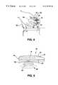
- FIG. 4is an illustration of the programmer from FIG. 1 being placed over a patient's implant site
- FIG. 5is a side view of the programmer from FIG. 1 as it is placed over a patient's implant site;
- FIG. 6is a block diagram of circuitry within the programmer from FIG. 1;
- FIG. 7is a schematic diagram of the circuitry within the programmer from FIG. 1;
- FIG. 8is a pinout diagram of an integrated circuit in the circuitry from FIG. 7;
- FIG. 9is a timing diagram illustrating a timed sampling key debouncing scheme implemented in the integrated circuit of FIG. 8 .
- FIG. 1there is shown a perspective view of a patient programmer 10 in accordance with one embodiment of the present invention.
- Programmer 10is a small, handheld, battery-powered programming device for use by implantable device patients to control and monitor the operation of their implanted devices.
- the disclosed embodimentis believed to be suitable, for example, for use in programming a Medtronic Model 7425 ItrelTM 3 implantable spinal cord stimulation system.
- programmer 10includes a downlink radio-frequency (RF) transmitter for transmitting programming signals to an implanted pulse generator (not shown in FIG. 1 ), and an uplink RF receiver to monitor the programming process and pulse generator status.
- RFradio-frequency
- Programmer 10may be used, in the presently disclosed embodiment of the invention, to turn the pulse generator on and off, similar to the magnet function of prior art implanted devices, as described above.
- programmer 10can also function to allow the patient to adjust amplitude, rate, and pulse width within lower and upper limits which are programmed into the implanted device by the physician using a physician programmer, such as the above-described Model 9760 or Hartlaub programmers.
- a physician programmersuch as the above-described Model 9760 or Hartlaub programmers.
- programmer 10 in accordance with the present inventionis not intended as a substitute for a conventional physician programmer.
- Programmer 10may have fewer or different programming capabilities than a physician programmer.
- the uplink RF receiver in programmer 10permits monitoring of the implanted device's battery depletion level, and the implanted device's on/off status. In other embodiments it could also indicate other status conditions or physiological parameters of the user.
- programmer 10comprises a main outer housing 12 , which is preferably made of injection-molded ABS and polycarbonate, hard plastic, or another suitably rugged material so as to be light-weight, yet not be easily damaged when carried by a patient, for example in a purse or pocket, or even dropped onto the floor.
- a battery compartment cover 14is disposed on a top surface of programmer 10 .
- a clip 16 or other fastening mechanismmay be disposed on a back end of programmer 10 , to facilitate opening of the battery compartment for battery replacement.
- FIG. 2is a partial top view of programmer 10 with battery compartment cover 14 removed. As shown in FIG. 2, also disposed within the battery compartment and protected by battery compartment cover 14 is a parameter control switch 17 and a volume control switch 18 , the functions of which to be hereinafter described in greater detail.
- a plurality of user keys 19 , 20 , 21 , and 22are disposed on the upper surface of programmer 10 , the functions of which will be hereinafter described in greater detail with reference to later Figures.
- Keys 19 , 20 , 21 , and 22preferably have a mechanical detail to give sensory indication to the user when sliding a finger from one key to another.
- an external antenna jack 26is provided for receiving a connector 27 from an optional external antenna 28 .
- a flip-down cap 29is provided to protect antenna jack 26 when no external antenna is used.
- the use of external antenna 28eliminates the need to place programmer 10 over the implant site during patient programming sessions. This can be helpful for a patient who cannot easily reach his or her implant site, due either to the patient's physical condition or to the location of the implant site.
- Antenna 28may be provided with an adhesive disc so that it may be affixed stably over the implant site during a patient programming session.
- the overall configuration of programmer 10is generally smooth and curved so as to fit comfortably in a patient's hand, with keys 19 , 20 , 21 , and 22 being readily accessible on the programmer's upper surface.
- Disposed along each side of housing 12are resilient finger grips 30 (only one of which is visible in the view of FIG. 1 ), which further facilitate comfortable and stable gripping by the patient.
- LEDs 32 , 34 , 36 , and 38are disposed on the underside of programmer 10 , which is illustrated in the bottom view of FIG. 3, disposed a plurality of light-emitting diodes (LEDs) 32 , 34 , 36 , and 38 .
- LEDs 32 , 34 , 36 , and 38are preferably disposed within housing 12 and are merely visible through translucent windows in housing 12 .
- reference numerals 32 , 34 , 36 , and 38will be used herein to refer to the individual LEDs which are visible on the underside of programmer 10 due to this conventional arrangement.
- LEDs 32 , 34 , 36 , and 38are implanted device and programmer status indicators, as will be hereinafter described in greater detail.
- FIG. 3Also shown in FIG. 3 is a “cross-hair” diagram and associated legend, designated generally with reference numeral 40 , which are imprinted on the underside of programmer 10 to assist the patient in proper positioning of programmer 10 over the implant site during a patient programming session.
- Legend 40which reads, e.g., “Center This Programmer Over Your IPG, ” instructs the patient where to place programmer 10 so that uplink RF signals transmitted from an implanted device can be received by the internal antenna (not shown) of programmer 10 , and conversely so that downlink telemetry signals transmitted from programmer 10 can be received by the implanted device's internal antenna.
- FIGS. 4 and 5wherein a patient 42 has placed programmer 10 against his or her body over the implant site of a device 44 in a conventional lower abdominal region of patient 42 .
- Downlink RF telemetry signalsare represented by dashed lines 46 in FIG. 5 .
- FIG. 6there is shown a block diagram of the internal circuitry of programmer 10 .
- ICintegrated circuit
- keys 19 , 20 , 21 , and 22are coupled to inputs of IC 50 , as are pulse control switch 17 and beeper control switch 18 .
- programmer 10includes a downlink telemetry RF transmitter, designated with reference numeral 52 in FIG. 6, and an uplink telemetry RF receiver, designated with reference numeral 54 in FIG. 6 .
- Transmitter circuit 52is coupled to a DOWNLINK DATA OUT terminal of IC 50
- receiver circuit 54is coupled to an UPLINK DATA IN terminal of IC 50 .
- the output from transmitter circuit 52is applied to an internal antenna 56 via external antenna jack 26 previously noted with reference to FIG. 1 .
- Optional external antenna 28previously described with reference to FIG. 1 is also removably coupled to antenna jack 26 .
- the connection between transmitter circuit 52 and internal antenna 56is made via antenna jack 26 , to facilitate the disabling of internal antenna 56 when external antenna 28 is plugged into jack 26 , in accordance with common practice in the art.
- Antenna jack 26is also coupled to an input of receiver circuit 54 , so that uplink telemetry signals received by internal antenna 56 (or by external antenna 28 ) may be applied thereto. Uplink telemetry signals received by receiver circuit 54 are then applied to the UPLINK DATA IN terminal of IC 50 .
- a beeperdesignated with reference numeral 58 in FIG. 6, is coupled to IC 50 to receive a control signal therefrom.
- Beeper 58provides an audible indication of certain programming events, as will be hereinafter described in greater detail.
- a 9-volt batteryhoused within the battery compartment of programmer 10 previously described with reference to FIG. 1, is coupled to respective power inputs (not shown) of IC 50 , transmitter circuit 52 , receiver circuit 54 , LEDs 32 , 34 , 36 , and 38 , and beeper 58 .
- IC 50includes voltage regulation circuitry, so that it can provide a regulated five volt output signal to receiver circuit 54 .
- FIG. 7there is shown a more detailed schematic diagram of the internal circuitry shown in block diagram form in FIG. 6 . Elements of FIG. 7 which are identical to those discussed with reference to FIG. 6 have retained identical reference numerals in FIG. 7 .
- the 9-volt battery described with reference to FIG. 6is identified with reference numeral 60 in FIG. 7 .
- Table 1there is set forth a component listing for the components shown in the schematic diagram of FIG. 7, along with their respective component values:
- Beeper Switch 18 disposed within the battery compartment of programmer 10is a three-position switch for enabling the user to turn the beeper off or select one of two resistors (R 1 and R 2 in FIG. 7) for volume settings for beeper 58 .
- Parameter Select Switch 17also disposed within the battery compartment, is a three-position switch for defining the function of INC and DEC keys 19 and 20 . Depending upon the position of switch 17 , INC and DEC keys 19 and 20 function to increase and decrease, respectively, the amplitude, rate, or pulse width of stimulating pulses delivered by implanted device 44 .
- IC 50is sequenced by a 5.6 MHz clock.
- the oscillator time baseis an external ceramic resonator designated as Y 1 in FIG. 7 .
- Capacitors C 17 and C 18 required for resonator Y 1are preferably on-chip in mask-programmable form, selectable up to 32-pF. External capacitors may also be used for fine-tuning.
- custom IC 50in the presently preferred embodiment of the invention, it is implemented as a logic state-machine controller which generates a serial bit pattern for RF downlink telemetry with data retrieved from an on-board ROM.
- IC 50provides drive signals to LED 38 .
- IC 50also provides drive signals to LEDs 32 , 34 , and 36 , and to beeper 58 based upon serial bit patterns received as uplink transmissions from implanted device 44 .
- Uplink telemetry signalsare demodulated by an integrated circuit designated as U 2 in FIG. 7 .
- This pinto be binary most significant bit (MSB).
- Implanted device 44will respond to the INC command only if in the IPG ON state.
- NVddWhen at NVdd, provides DEC downlink signal for parameter selected by the state of XRTSELB and XPWSELB to downlink as for XINCPB (see description for pin 10 above). Internal pullup to Vdd. 12 XINCSB Reserved for future functions. 13 XDECSB Reserved for future functions. 14 XEPIB Reserved for future functions.
- VssVdd ⁇ (1.4 ⁇ 0.3 volts)
- RFGND Negative battery input (NVdd)for driving RFP and RFN outputs.
- VBE_OUTInternal power supply pin brought out for capacitor filter.
- PBIASInternal power supply pin brought out for capacitor filter.
- LED indicationtriggered by any key push, regardless of the presence of uplink signal. LED to remain off if programmer battery is at or below end-of-life (EOL) 38 XEPILEDB Reserved for future functions. 39 XIBLEDB Indicator LED for status of implanted device's battery. Turns on, or blinks, for six seconds, each time the RXDATA indicates that the implanted device's battery is good or low, respectively. LED to remain off if implanted device's battery is at or below EOL. 40 XOFFLEDB LED for indicating that implanted device 44 is off.
- an on-chip “watchdog timer”counts successive bad uplinks generated during one continuous keypress of any key. This detects a key that is held pressed for an extended period of time, for example if programmer 10 is jammed into a user's pocket or purse.
- 32 consecutive bad uplinksi.e., no valid uplinks
- LEDs 32 , 34 , 36 , and 38are deactivated, and downlink telemetry transmissions are terminated.
- the regulated voltage Vregis turned off to power-down the receiver IC U 2 . This conserves programmer battery life. Operation is restored 400 milliseconds after the release of all keys.
- the watchdog timer in IC 50operates to cause a shutdown after only eight bad uplinks corresponding to a second predetermined period of time, unless a good uplink is received. This further limits battery drain due to intermittent keypresses due to programmer 10 being jammed in a user's pocket or purse while the user is moving around in way that creates such intermittent stuck key conditions.
- XPBLED1B and XPBLED2B, pins 36 and 37 of IC 50will indicate battery status for six seconds.
- IC 50also preferably is provided with key debouncing capability, well known to those of ordinary skill in the art, associated with key input pins 8 - 17 to IC 50 .
- IC 50employs a timed sampling scheme to debounce and add noise immunity to key switches.
- timed sampling schemevarious minimum time intervals associated with key depression are defined, as shown in the timing diagram of FIG. 9 .
- the various time intervals identified in FIG. 9are defined as set forth in the following Table 3:
- Downlink telemetryconsists of 33 RF bursts, as determined by the serial data programmed into the ROM of IC 50 .
- the first RF burstis a start burst, the rest are data bits.
- Programming informationis encoded serially to implanted device 44 via pulse interval modulation, which is well known in the art. Data is encoded by the time between falling edges of transmitted RF bursts.
- the 32 downlink bits B 0 through B 31are defined as set forth in the following Table 4:
- the error check wordis determined by calculation of the parameter and value codes only. Starting with the least significant bit (LSB) of the parameter, each parameter and value bit is sequenced through a cyclic redundancy check (CRC) equation, in accordance with known practice.
- LSBleast significant bit
- CRCcyclic redundancy check
- Downlinkis initiated by depressing any of the four user keys 19 , 20 , 21 , or 22 . Depression of any key shorts a respective pin of IC 50 to NVDD. If two or more keys are depressed simultaneously, only one key will be recognized, with priority per the following Table 5:
- implanted device 44If implanted device 44 is OFF, it will accept only the DEC (key 20 ) and ON (key 21 ) commands. If an unacceptable command is given, beeper 58 will beep three times. If an INC or DEC command is given (i.e., if keys 19 or 20 , respectively, are depressed), and the parameter is already at its respective limit (programmed by the doctor, as previously described), beeper 58 will beep three times.
- a second presswill not be acknowledged until 120 milliseconds after completion of the beeper function. This desensitizes the keys to prevent unwanted multiple keypresses from patients who have spasticity in their fingers.
- the actual downlink signalwill be delayed for approximately 150 milliseconds to provide time for the receiver chip to stabilize for uplink reception. This delay is only for the first downlink command when the programmer comes out of the sleep mode.
- IC U 2For uplink telemetry reception, IC U 2 (see FIG. 7) is used. IC U 2 is an off-the-shelf receiver chip, such as the Signetics #TDA3047. IC U 2 responds to uplink signals such as those transmitted by the Medtronic Model 7425 ItrelTM. IC U 2 demodulates the digital bits in the uplink telemetry signal, and provides the demodulated bit stream to IC 50 , at pin 22 (XRXDATA). IC 50 decodes the demodulated uplink code and then drives appropriate ones of LEDs 32 , 34 , or 36 , and beeper 58 . In the presently preferred embodiment, an uplink transmission consists of 19 total RF bursts from implanted device 44 . The uplink transmission is sent from implanted device 44 12 ⁇ 4 mSec after completion of each downlink.
- Uplink codesare accepted and processed following downlink whether downlink activation keys are subsequently released or remain depressed.
- IC 50responds to data from the last correct uplink signal received if a key remains depressed. This allows LEDs 32 , 34 , and 36 , and beeper 58 to function properly with the last uplink signal received if programmer 10 is removed from the implant site of implanted device 44 with the user's finger still on a key, still transmitting downlinks from too far a distance to be usable. LEDs 32 , 34 , 36 , and 38 hold their indication status for six seconds after release of a key, to give the patient an opportunity to view them.
- No uplinkis transmitted by implanted device 44 if a bad access code is received (i.e., programmer 10 and implanted device 44 are incompatible), a bad error code is received, or an incorrect pulse interval (indicative of noise) is received.
- Uplink bitsare encoded via pulse interval modulation. Data is encoded by the time between leading edges of transmitted RF bursts. In the presently preferred embodiment of the invention, the nineteen uplink bits have a format as set forth in the following Table 6:
- IC 50senses uplink synchronization bits by looking for a logic one, and then waiting past the remaining ones until a zero is detected. Then, IC 50 accepts and processes subsequent data. This means that if some of the first ones are uplinked and missed due to receiver gain control stabilization, uplink can still be properly received.
- LEDs 32 , 34 , 36 , and 38activation thereof is used to provide a visual indication of programming events.
- Programmer battery status LED 38is activated whenever any key is depressed.
- the remaining LEDs 32 , 34 , and 36are activated following the receipt of an uplink signal, with particular ones of LEDs 32 , 34 , and 36 lighting based upon the particular uplink signal data.
- LEDs 32 , 34 , 36 , and 38remain on for six seconds after any key release. After this six-second time-out has expired, IC 50 enters a standby mode until a new key-press occurs. This advantageously minimizes power consumption during standby to conserve battery life.
- LEDs 32 , 34 , and 36will indicate status based upon the last good uplink received. If any key 19 , 20 , 21 , or 22 is subsequently pressed before a prior six-second LED timeout has expired, any of the LEDs 32 , 34 , 36 , or 38 that were on as a result of the first key depression will remain on until updating upon completion of receipt of a valid uplink. If an unsatisfactory uplink or no uplink is received, only Programmer Battery Status LED 38 will be active. Programmer Battery Status LED 38 and implantable device battery status LED 36 light to indicate a good respective battery, blink at a rate of 2 to 4 times per second if the respective battery is low, and remain off if the battery is at EOL.
Landscapes
- Health & Medical Sciences (AREA)
- Engineering & Computer Science (AREA)
- Biomedical Technology (AREA)
- Nuclear Medicine, Radiotherapy & Molecular Imaging (AREA)
- Radiology & Medical Imaging (AREA)
- Life Sciences & Earth Sciences (AREA)
- Animal Behavior & Ethology (AREA)
- General Health & Medical Sciences (AREA)
- Public Health (AREA)
- Veterinary Medicine (AREA)
- Human Computer Interaction (AREA)
- Electrotherapy Devices (AREA)
Abstract
Description
This invention relates generally to the field of body-implantable medical device systems, and more particularly to a programming apparatus for a body-implantable human tissue stimulator.
In the medical field, various types of automatic, body-implantable devices are known and commercially-available. One of the more common types of body-implantable devices is the cardiac pacemaker, which operates to deliver electrical stimulating pulses to a patient's heart. A cardiac pacemaker is disclosed, for example, in U.S. Pat. No. 5,052,388 to Sivula et al, entitled “Method and Apparatus for Implementing Activity Sensing in a Pulse Generator.” Implantable cardioverters, defibrillators, and drug pumps are other examples of presently available automatic implantable devices. An example of a combination pacemaker/cardioverter/defibrillator is described in U.S. Pat. No. 5,179,946 to Weiss, entitled “Apparatus and Method for Arrhythmia Detection by Variations in the Transcardiac Impedance Between Defibrillation Patches.”
It has also been proposed in the prior art to provide implantable tissue stimulators for controlling nerve or muscle response, for alleviating pain, or to treat various neurological and/or physiological disorders, such as cerebral palsy, epilepsy, and the like. Examples of such devices are discussed in the following U.S. patents: U.S. Pat. No. 4,232,679 to Schulman, entitled “Programmable Human Tissue Stimulator;” U.S. Pat. No. 4,735,204 to Sussman et al., entitled “System for Controlling an Implanted Neural Stimulator;” and in U.S. Pat. No. 4,793,353 to Borkan, entitled “Non-Invasive Multiprogrammable Tissue Stimulator and Method. ” A commercially-available example of an implantable tissue stimulator is the Model 7425 Itrel™ 3 Implantable Pulse Generator, manufactured by Medtronic, Inc., Minneapolis, Minn. The Itrel™ 3 is a spinal cord stimulating system prescribed to alleviate chronically-recurring pain.
It is very common for automatic implantable devices to be non-invasively controllable by means of an external programming apparatus of some sort, so that an implanted device's operational modes and/or parameters may be adjusted, for example to optimize its therapeutic efficacy or in response to post-implant changes in a patient's condition. Often, such non-invasive control is exercised by a physician in a clinical setting.
Perhaps one of the simplest arrangements for facilitating non-invasive control of an implanted device involves providing a magnetic reed switch in the implantable device. After implant, the reed switch can be actuated (closed) by placing a magnet over the implant site. Reed switch closure may then be used, for example, to alternately activate and deactivate the device. Alternatively, some variable parameter of the device (e.g., the pacing rate of an implantable cardiac pacemaker) can be adjusted up or down by incremental amounts based upon the duration of the reed switch closure interval. Many different schemes utilizing a reed switch to adjust operational parameters of medical devices have been developed. See, for example, U.S. Pat. No. 3,311,111 to Bowers; U.S. Pat. No. 3,518,997 to Sessions; U.S. Pat. No. 3,623,486 to Berkovits; U.S. Pat. No. 3,631,860 to Lopin; U.S. Pat. No. 3,738,369 to Adams et al., U.S. Pat. No. 3,805,796 to Terry, Jr.; U.S. Pat. No. 4,066,086 to Alferness et al.; and the above-reference U.S. Pat. No. 4,735,204 to Sussman et al.
Although the relatively simple reed-switch closure arrangement is suitable for the purposes of controlling or adjusting a limited number of operational parameters or modes of an implanted device, it has proven beneficial to provide a means for more efficiently communicating programming information to an implanted device, so that a greater number of the device's operating modes and parameters can be adjusted. In state-of-the-art cardiac pacemakers, for example, a partial list of the types of programmable parameters includes: upper and lower pacing rate limits, stimulating pulse width and/or amplitude, sense amplifier sensitivity, pacing mode, activity- or rate-response settings (e.g., pacing rate acceleration and deceleration, activity threshold, activity detection criteria, and the like), A-V delay times, refractory and blanking periods, and so on. It has also proven desirable for implanted devices themselves to be able to communicate information to an external programming apparatus.
In response to the foregoing considerations, various telemetry systems for providing the necessary communications channels between an external unit and an implanted device have been developed. Telemetry systems are disclosed, for example, in the following U.S. patents: U.S. Pat. No. 4,539,992 to Calfee et al. entitled “Method and Apparatus for Communicating With Implanted Body Function Stimulator”; U.S. Pat. No. 4,550,732 to Batty Jr. et al. entitled “System and Process for Enabling a Predefined Function Within An Implanted Device”; U.S. Pat. No. 4,571,589 to Slocum et al. entitled “Biomedical Implant With High Speed, Low Power Two-Way Telemetry”; U.S. Pat. No. 4,676,248 to Berntson entitled “Circuit for Controlling a Receiver in an Implanted Device”; U.S. Pat. No. 5,127,404 to Wyborny et al. entitled “Telemetry Format for Implanted Medical Device”; U.S. Pat. No. 4,211,235 to Keller, Jr. et al. entitled “Programmer for Implanted Device”; U.S. Pat. No. 4,374,382 to Markowitz entitled “Marker Channel Telemetry System for a Medical Device”; and U.S. Pat. No. 4,556,063 to Thompson et al. entitled “Telemetry System for a Medical Device”.
Typically, telemetry systems such as those described in the above-referenced patents are employed in conjunction with an external programming/processing unit. One programmer for non-invasively programming a cardiac pacemaker is described in its various aspects in the following U.S. patents to Hartlaub et al., each commonly assigned to the assignee of the present invention and each incorporated by reference herein: U.S. Pat. No. 4,250,884 entitled “Apparatus For and Method Of Programming the Minimum Energy Threshold for Pacing Pulses to be Applied to a patient's Heart”; U.S. Pat. No. 4,273,132 entitled “Digital Cardiac Pacemaker with Threshold Margin Check”; U.S. Pat. No. 4,273,133 entitled Programmable Digital Cardiac Pacemaker with Means to Override Effects of Reed Switch Closure”; U.S. Pat. No. 4,233,985 entitled “Multi-Mode Programmable Digital Cardiac Pacemaker”; U.S. Pat. No. 4,253,466 entitled “Temporary and Permanent Programmable Digital Cardiac Pacemaker”; and U.S. Pat. No. 4,401,120 entitled “Digital Cardiac Pacemaker with Program Acceptance Indicator”.
Aspects of the programmer that is the subject of the foregoing Hartlaub et al. patents (hereinafter “the Hartlaub programmer”) are also described in U.S. Pat. No. 4,208,008 to Smith, entitled “Pacing Generator Programming Apparatus Including Error Detection Means” and in U.S. Pat. No. 4,236,524 to Powell et al., entitled “Program Testing Apparatus”. The Smith '008 and Powell et al. '524 patents are also incorporated by reference herein in their entirety.
Most commonly, telemetry systems for implantable medical devices employ a radio-frequency (RF) transmitter and receiver in the device, and a corresponding RF transmitter and receiver in the external programming unit. Within the implantable device, the transmitter and receiver utilize a wire coil as an antenna for receiving downlink telemetry signals and for radiating RF signals for uplink telemetry. The system is modelled as an air-core coupled transformer. Examples of such a telemetry system are shown in the above-referenced Thompson et al. '063 and Hartlaub et al. '120 patents.
In order to communicate digital data using RF telemetry, a digital encoding scheme such as is described in U.S. Pat. No. 5,127,404 to Wyborny et al. entitled “Improved Telemetry Format” is used. In particular, for downlink telemetry a pulse interval modulation scheme may be employed, wherein the external programmer transmits a series of short RF “bursts” or pulses in which the during of an interval between successive pulses (e.g., the interval from the trailing edge of one pulse to the trailing edge of the next) encodes the data. In particular, a shorter interval encodes a digital “0” bit while a longer interval encodes a digital “1” bit.
For uplink telemetry, a pulse position modulation scheme may be employed to encode uplink telemetry data. For pulse position modulation, a plurality of time slots are defined in a data frame, and the presence or absence of pulses transmitted during each time slot encodes the data. For example, a sixteen position data frame may be defined, wherein a pulse in one of the time slots represents a unique four bit portion of data. The Wyborny et al. '404 patent is hereby incorporated by reference herein in its entirety.
Programming units such as the above-described Hartlaub et al. programmer typically interface with the implanted device through the use of a programming head or programming paddle, a handheld unit adapted to be placed on the patient's body over the implant site of the patient's implanted device. A magnet in the programming head effects reed switch closure in the implanted device to initiate a telemetry session. Thereafter, uplink and downlink communication takes place between the implanted device's transmitter and receiver and a receiver and transmitter disposed within the programming head.
State-of-the-art implantable medical device programmers, as exemplified by the Model 9760 programming unit, manufactured by Medtronic, Inc., Minneapolis, Minn., facilitate the non-invasive control of a full range of operational and diagnostic functions of implanted devices. Accordingly, such programming units are typically used by physicians or other medical personnel in a clinical setting, so that the patient's condition can be carefully monitored during the programming session. Those of ordinary skill in the art will appreciate, however, that in some cases it may be desirable to provide means for allowing the patient to exercise some degree of control over device operation, even outside of the clinical setting. It is desirable, for example, for a patient with an implanted spinal cord stimulation system to be able to trigger the device to deliver a stimulating pulse whenever the patient experiences an episode of pain that the device is intended to alleviate.
To address the need for patient control of an implanted device, so-called patient programmers, such as the Medtronic Model 7433, were developed. The Model 7433 was designed to facilitate patient control over Medtronic implantable tissue stimulators. In operation, the Model 7433 was placed over the implant site and a downlink telemetry link was established, whereby a single cycle of stimulation could be initiated by the patient.
Although the Model 7433 patient programmer has proven satisfactory for its intended purpose, it is believed that the present invention represents an advancement over the prior art, as exemplified by the Model 7433, in several aspects. In particular, it is believed that no prior art programmer intended for use by patients, has incorporated features in recognition of factors such as the varying characteristics of potential patients who will use a patient programmer, including such potential patients' age, education, dexterity, and physical and mental health.
Accordingly, the present invention relates to a patient programmer for facilitating patient control over an implanted medical device, such as an implanted spinal cord stimulator or the like.
In accordance with the present invention, a portable, light-weight, easy to use patient programmer is provided for enabling a patient to control the operation of his or her implanted device outside of a clinical setting.
The programmer in accordance with the disclosed embodiment of the invention incorporates features which make it easier for users of varying ages, education levels, dexterity levels, physical and mental health to safely control the operation of their implanted devices, within predefined limits established by a physician or clinician.
In accordance with one aspect of the invention, circuitry is provided for avoiding battery depletion and/or undesired programmer/implanted device communication in the event that the programmer's key is accidentally depressed (for example, due to being jammed into a purse or pocket) or is depressed repeatedly or continuously over an extended period of time.
In accordance with another aspect of the invention, the programmer provides tactile, audible, and visible feedback to the user to convey information regarding the proper (or improper) operation of the programmer and the implanted device. For example, the device includes a beeper and light-emitting diodes (LEDs) to indicate, for example, that a desired programming function has been successful or unsuccessful.
The above-described and other aspects of the present invention may be better understood and appreciated with reference to a detailed description of a specific embodiment of the invention, when read in conjunction with the accompanying drawings, wherein:
FIG. 1 is a perspective view of a handheld patient programmer in accordance with one embodiment of the present invention;
FIG. 2 is a top view of a front portion of the programmer from FIG. 1, with the battery compartment cover removed;
FIG. 3 is a bottom view of the programmer from FIG. 1;
FIG. 4 is an illustration of the programmer from FIG. 1 being placed over a patient's implant site;
FIG. 5 is a side view of the programmer from FIG. 1 as it is placed over a patient's implant site;
FIG. 6 is a block diagram of circuitry within the programmer from FIG. 1;
FIG. 7 is a schematic diagram of the circuitry within the programmer from FIG. 1;
FIG. 8 is a pinout diagram of an integrated circuit in the circuitry from FIG. 7; and
FIG. 9 is a timing diagram illustrating a timed sampling key debouncing scheme implemented in the integrated circuit of FIG.8.
Mechanical Description
Referring to FIG. 1, there is shown a perspective view of apatient programmer 10 in accordance with one embodiment of the present invention.Programmer 10 is a small, handheld, battery-powered programming device for use by implantable device patients to control and monitor the operation of their implanted devices. The disclosed embodiment is believed to be suitable, for example, for use in programming a Medtronic Model 7425Itrel™ 3 implantable spinal cord stimulation system.
As will be hereinafter described in greater detail,programmer 10 includes a downlink radio-frequency (RF) transmitter for transmitting programming signals to an implanted pulse generator (not shown in FIG.1), and an uplink RF receiver to monitor the programming process and pulse generator status.Programmer 10 may be used, in the presently disclosed embodiment of the invention, to turn the pulse generator on and off, similar to the magnet function of prior art implanted devices, as described above. Unlike magnet/reed switch configurations, however,programmer 10 can also function to allow the patient to adjust amplitude, rate, and pulse width within lower and upper limits which are programmed into the implanted device by the physician using a physician programmer, such as the above-described Model 9760 or Hartlaub programmers. In this sense, those of ordinary skill in the art will appreciate thatprogrammer 10 in accordance with the present invention is not intended as a substitute for a conventional physician programmer.Programmer 10 may have fewer or different programming capabilities than a physician programmer.
In the embodiment shown, the uplink RF receiver inprogrammer 10 permits monitoring of the implanted device's battery depletion level, and the implanted device's on/off status. In other embodiments it could also indicate other status conditions or physiological parameters of the user.
With continued reference to FIG. 1,programmer 10 comprises a mainouter housing 12, which is preferably made of injection-molded ABS and polycarbonate, hard plastic, or another suitably rugged material so as to be light-weight, yet not be easily damaged when carried by a patient, for example in a purse or pocket, or even dropped onto the floor. Abattery compartment cover 14 is disposed on a top surface ofprogrammer 10. Aclip 16 or other fastening mechanism may be disposed on a back end ofprogrammer 10, to facilitate opening of the battery compartment for battery replacement. FIG. 2 is a partial top view ofprogrammer 10 withbattery compartment cover 14 removed. As shown in FIG. 2, also disposed within the battery compartment and protected bybattery compartment cover 14 is aparameter control switch 17 and avolume control switch 18, the functions of which to be hereinafter described in greater detail.
As shown in FIGS. 1 and 2, a plurality ofuser keys programmer 10, the functions of which will be hereinafter described in greater detail with reference to later Figures.Keys
On the front end ofprogrammer 10, anexternal antenna jack 26 is provided for receiving aconnector 27 from an optionalexternal antenna 28. A flip-downcap 29 is provided to protectantenna jack 26 when no external antenna is used. The use ofexternal antenna 28 eliminates the need to placeprogrammer 10 over the implant site during patient programming sessions. This can be helpful for a patient who cannot easily reach his or her implant site, due either to the patient's physical condition or to the location of the implant site.Antenna 28 may be provided with an adhesive disc so that it may be affixed stably over the implant site during a patient programming session.
As will be appreciated by those of ordinary skill in the art, the overall configuration ofprogrammer 10 is generally smooth and curved so as to fit comfortably in a patient's hand, withkeys housing 12 are resilient finger grips30 (only one of which is visible in the view of FIG.1), which further facilitate comfortable and stable gripping by the patient.
On the underside ofprogrammer 10, which is illustrated in the bottom view of FIG. 3, are disposed a plurality of light-emitting diodes (LEDs)32,34,36, and38. (Those of ordinary skill in the art will appreciate thatLEDs housing 12 and are merely visible through translucent windows inhousing 12. For simplicity,reference numerals programmer 10 due to this conventional arrangement.)LEDs
Also shown in FIG. 3 is a “cross-hair” diagram and associated legend, designated generally withreference numeral 40, which are imprinted on the underside ofprogrammer 10 to assist the patient in proper positioning ofprogrammer 10 over the implant site during a patient programming session.Legend 40, which reads, e.g., “Center This Programmer Over Your IPG, ” instructs the patient where to placeprogrammer 10 so that uplink RF signals transmitted from an implanted device can be received by the internal antenna (not shown) ofprogrammer 10, and conversely so that downlink telemetry signals transmitted fromprogrammer 10 can be received by the implanted device's internal antenna. This is depicted in FIGS. 4 and 5, wherein apatient 42 has placedprogrammer 10 against his or her body over the implant site of adevice 44 in a conventional lower abdominal region ofpatient 42. Downlink RF telemetry signals are represented by dashedlines 46 in FIG.5.
Electrical Description
Turning now to FIG. 6, there is shown a block diagram of the internal circuitry ofprogrammer 10. At the heart of the circuitry represented in FIG. 2 is a custom integrated circuit (IC)50 to be hereinafter described in greater detail. As shown in FIG. 2,keys IC 50, as arepulse control switch 17 andbeeper control switch 18.
As previously noted,programmer 10 includes a downlink telemetry RF transmitter, designated withreference numeral 52 in FIG. 6, and an uplink telemetry RF receiver, designated withreference numeral 54 in FIG.6.Transmitter circuit 52 is coupled to a DOWNLINK DATA OUT terminal ofIC 50, whilereceiver circuit 54 is coupled to an UPLINK DATA IN terminal ofIC 50. The output fromtransmitter circuit 52 is applied to aninternal antenna 56 viaexternal antenna jack 26 previously noted with reference to FIG.1. Optionalexternal antenna 28, previously described with reference to FIG. 1 is also removably coupled toantenna jack 26. The connection betweentransmitter circuit 52 andinternal antenna 56 is made viaantenna jack 26, to facilitate the disabling ofinternal antenna 56 whenexternal antenna 28 is plugged intojack 26, in accordance with common practice in the art.
A beeper, designated withreference numeral 58 in FIG. 6, is coupled toIC 50 to receive a control signal therefrom.Beeper 58 provides an audible indication of certain programming events, as will be hereinafter described in greater detail.
A 9-volt battery, housed within the battery compartment ofprogrammer 10 previously described with reference to FIG. 1, is coupled to respective power inputs (not shown) ofIC 50,transmitter circuit 52,receiver circuit 54,LEDs beeper 58. For simplicity, the connections between the battery and these elements are not shown in FIG.6.IC 50 includes voltage regulation circuitry, so that it can provide a regulated five volt output signal toreceiver circuit 54.
Turning now to FIG. 7, there is shown a more detailed schematic diagram of the internal circuitry shown in block diagram form in FIG.6. Elements of FIG. 7 which are identical to those discussed with reference to FIG. 6 have retained identical reference numerals in FIG.7. The 9-volt battery described with reference to FIG. 6 is identified withreference numeral 60 in FIG.7. In the following Table 1, there is set forth a component listing for the components shown in the schematic diagram of FIG. 7, along with their respective component values:
| TABLE 1 | |||
| COMPONENT | VALUE | ||
| C1 | 0.1 μF | ||
| C2 | 0.1 μF | ||
| C3 | 0.01 μF | ||
| C4 | 1800 μF | ||
| C5 | 0.1 μF | ||
| C6 | 0.047 μF | ||
| C7 | 0.033 μF | ||
| C8 | 0.001 μF | ||
| C9 | 1800 μf | ||
| C10 | 0.01 μf | ||
| C11 | 0.1 μf | ||
| C12 | 0.001 μf | ||
| C13 | 0.01 μf | ||
| C14 | 0.1 μf | ||
| 10 μf (tantalum) | |||
| C16 | 0.1 μf | ||
| 33 | |||
| C18 | |||
| 33 pF | |||
| R1 | 200Ω | ||
| R2 | 432Ω | ||
| R3 | 430Ω | ||
| D1-D4, | DIODES | ||
| D6-D24 | |||
| D5 | LL103 SCHOTTKY | ||
| L2 | 420 μH | ||
| Q1 | S19952DY | ||
| Q2 | S19952DY | ||
| Y1 | 5.6MHz OSC. | ||
| U2 | TDA3047 IC | ||
As shown in FIG. 7,Beeper Switch 18 disposed within the battery compartment ofprogrammer 10 is a three-position switch for enabling the user to turn the beeper off or select one of two resistors (R1 and R2 in FIG. 7) for volume settings forbeeper 58.Parameter Select Switch 17, also disposed within the battery compartment, is a three-position switch for defining the function of INC andDEC keys switch 17, INC andDEC keys device 44.
Integrated Circuitry
Regardingcustom IC 50, in the presently preferred embodiment of the invention, it is implemented as a logic state-machine controller which generates a serial bit pattern for RF downlink telemetry with data retrieved from an on-board ROM.IC 50 provides drive signals toLED 38.IC 50 also provides drive signals toLEDs beeper 58 based upon serial bit patterns received as uplink transmissions from implanteddevice 44. Uplink telemetry signals are demodulated by an integrated circuit designated as U2 in FIG.7.
With reference now to FIG. 8, which showsIC 50 from the circuit of FIG. 7 in isolation, the following Table 2 sets forth the pin definition for IC50:
| TABLE 2 | |||
| PIN NO. | DESCRIPTION | ||
| 1 | XACCSEL0 | Access code select pin. To be at Vdd or left open via | |
| PC board layout. This pin, in conjunction with | |||
| XACCSEL1 and XACCSEL2, will select pulse generator | |||
| access codes. This pin to be binary least significant bit | |||
| (LSB). Internal pulldown to Vss. | |||
| 2 | XACCSEL1 | Access code select pin. To be at Vdd or left open via | |
| PC board layout. This pin, in conjunction with | |||
| XACCSEL0 and XACCSEL2, will select pulse generator | |||
| access codes. Internal pulldown to Vss. | |||
| 3 | XACCSEL2 | Access code select pin. To be at Vdd or left open via | |
| PC board layout. This pin, in conjunction with | |||
| XACCSEL0 and XACCSEL1, will select pulse generator | |||
| access codes. This pin to be binary most significant | |||
| bit (MSB). Internal pulldown to Vss. | |||
| 4 | TCK | Test pin. TAP controller test clock input. Internal | |
| pullup to | |||
| 5 | TMS | Test pin. TAP controller machine state control. | |
| Internal pullup to | |||
| 6 | TDO | Test pin. TAP controller data output. | |
| 7 | TDI | Test pin. TAP controller data input. Internal pullup to | |
| 8 | XONB | Keyboard input pin. When at NVdd, provides ON code | |
| downlink signal. Internal pullup to Vdd. | |||
| 9 | XOFFB | Keyboard input pin. When at NVdd, provides OFF | |
| code downlink signal. | |||
| 10 | XINCPB | Keyboard input pin. Implanted | |
| to the INC command only if in the IPG ON state. | |||
| When at NVdd, this pin provides | |||
| downlink signal for parameter selected by state of | |||
| XRTSELB and XPWSELB per the following: | |||
| PIN | 20 | |||
| 1 | 1 | |||
| RATE | 0 | 1 | ||
| 1 | 0 |
| (0 = NVdd, 1 = Vdd) |
| 11 | XDECPB | Keyboard input pin. When at NVdd, provides DEC | |
| downlink signal for parameter selected by the state of | |||
| XRTSELB and XPWSELB to downlink as for XINCPB | |||
| (see description for | |||
| Vdd. | |||
| 12 | XINCSB | Reserved for future functions. | |
| 13 | XDECSB | Reserved for future functions. | |
| 14 | XEPIB | Reserved for future functions. | |
| 15 | XF1B | Reserved for future functions. | |
| 16 | XF2B | Reserved for future functions. | |
| 17 | XBCHKB | Reserved for future functions. | |
| 18 | XMSBPAR | Reserved for future functions. | |
| 19 | XRTSELB | Input pin to select Rate (see description of | |
| 10 above). Internal pullup to Vdd. | |||
| 20 | XPWSELB | Input pin to select Pulse Width (see description of | |
| 21 | XCH1SELB | Reserved for future functions. | |
| 22 | XRXDATA | Receive uplink data input from RF demodulator IC U2. | |
| 23 | VSS | Negative logic power supply pin brought out for | |
| capacitor filter. Vss = Vdd − (1.4 ± 0.3 volts) | |||
| 24 | RFGND | Negative battery input (NVdd) for driving RFP and RFN | |
| outputs. | |||
| 25 | RFP | Pulse interval modulated 175 kHz, RF output from | |
| 50. Used to drive external RF output transistors Q1 | |||
| and Q2. Output must switch between Vdd and NVdd | |||
| supply rails. During uplink reception, this pin is at | |||
| NVdd. Inverse of XRFN. | |||
| 26 | RFN | Inverse of XRFP. | |
| 27 | RFPWR | Positive battery input (Vdd) for driving RFP and RFN | |
| outputs. | |||
| 28 | VREF | VREG filter/oxide stress test. | |
| 29 | VREG | Switched, regulated, negative power supply for | |
| external receiver IC U2. Regulated at 5 volts | |||
| referenced to Vdd. Capable of sinking 3 mA. | |||
| 30 | VBE_OUT | Internal power supply pin brought out for capacitor | |
| filter. | |||
| 31 | PBIAS | Internal power supply pin brought out for capacitor | |
| filter. | |||
| 32 | DIG_RST | Test pin, input. Resets functional digital logic. Internal | |
| pulldown to Vss. | |||
| 33 | NVDD | Negative 9 volt battery power supply pin. | |
| 34 | XBPRB | Beeper driver output. Provides an open drain FET that | |
| sinks beeper current to NVdd to activate beeper. | |||
| 35 | LEDGND | NVdd power supply pin for | |
| 36 | XPBLED2B | LED output identical in function to XPBLED1B ( | |
| below). | |||
| 37 | XPBLED1B | Low battery indicator. Turns on, or blinks, for six | |
| seconds upon any patient key depression if the battery | |||
| is good or low, respectively. LED indication triggered | |||
| by any key push, regardless of the presence of uplink | |||
| signal. LED to remain off if programmer battery is at | |||
| or below end-of-life (EOL) | |||
| 38 | XEPILEDB | Reserved for future functions. | |
| 39 | XIBLEDB | Indicator LED for status of implanted device's battery. | |
| Turns on, or blinks, for six seconds, each time the | |||
| RXDATA indicates that the implanted device's battery | |||
| is good or low, respectively. LED to remain off if | |||
| implanted device's battery is at or below EOL. | |||
| 40 | XOFFLEDB | LED for indicating that implanted | |
| Turns on for six seconds each time the RXDATA | |||
| indicates that implanted | |||
| 41 | XONLEDB | LED for indicating that implanted | |
| Turns on for six seconds each time the RXDATA | |||
| indicates that implanted | |||
| 42 | XOSC1 | Input pin for crystal or ceramic oscillator Y1 to control | |
| frequency of IC oscillator. Frequency = 5.6 MHz (an | |||
| integer multiple of 175 KHz to enable same oscillator | |||
| to generate system clock and RF data pulse drive. | |||
| 43 | XOSC2 | See description for XOSC1 above. | |
| 44 | Positive | 9 volt power supply pin. Vdd is considered to | |
| be chip ground. | |||
In accordance with one aspect of the present invention, an on-chip “watchdog timer” counts successive bad uplinks generated during one continuous keypress of any key. This detects a key that is held pressed for an extended period of time, for example ifprogrammer 10 is jammed into a user's pocket or purse. When32 consecutive bad uplinks (i.e., no valid uplinks) are counted, which would occur if a key depressed whenprogrammer 10 is not near the implant site for a predetermined period of time,LEDs
Further in accordance with the presently disclosed embodiment of the invention, upon the next keypress after a watchdog shutdown, the watchdog timer inIC 50 operates to cause a shutdown after only eight bad uplinks corresponding to a second predetermined period of time, unless a good uplink is received. This further limits battery drain due to intermittent keypresses due toprogrammer 10 being jammed in a user's pocket or purse while the user is moving around in way that creates such intermittent stuck key conditions. When all keys are released, operation is again restored; and XPBLED1B and XPBLED2B, pins36 and37 ofIC 50, will indicate battery status for six seconds.
| TABLE 3 | ||
| VALUE | ||
| TIME INTERVAL | (in milli- | |
| DESIGNATION | seconds) | |
| Tminivp |
| 26 | Minimum time for initial | |
| Tminimvp | ||
| 16 | Minimum time for multiple valid | |
| presses | ||
| Tminvr | 120 | Minimum time for valid release |
| Tminibpd | 721 | Minimum de1ay (worst case) between |
| initial button presses | ||
| Tminmbpd | 561 | Minimum de1ay (worst case) between |
| multiple button presses | ||
Telemetry
Downlink telemetry consists of 33 RF bursts, as determined by the serial data programmed into the ROM ofIC 50. The first RF burst is a start burst, the rest are data bits. Programming information is encoded serially to implanteddevice 44 via pulse interval modulation, which is well known in the art. Data is encoded by the time between falling edges of transmitted RF bursts.
In the presently preferred embodiment of the invention, the 32 downlink bits B0 through B31 are defined as set forth in the following Table 4:
| TABLE 4 | ||
| DESCRIPTION | BIT NOS. | VALUE (HEX) |
| Access code | B0-B7 | varies with device |
| Parameter code | B8-B15 | INC | DEC | |
| Rate | 3C | 3D | ||
| Pulse Width | 4C | 4D | ||
| Amplitude | 5C | 5D |
| ON/OFF = 60 | ||
| Parameter value | B16-B23 | ON = 01 |
| OFF = 00 | ||
| INC/DEC = don't care | ||
| Error check word | B24-B31 | varies with transmission |
The error check word is determined by calculation of the parameter and value codes only. Starting with the least significant bit (LSB) of the parameter, each parameter and value bit is sequenced through a cyclic redundancy check (CRC) equation, in accordance with known practice.
Downlink is initiated by depressing any of the fouruser keys IC 50 to NVDD. If two or more keys are depressed simultaneously, only one key will be recognized, with priority per the following Table 5:
| TABLE 5 | ||
| KEY | ||
| 1 | OFF (key 22) | |
| 2 | DEC (key | |
| 20) | ||
| 3 | ON (key 21) | |
| 4 | INC (key 19) | |
If implanteddevice 44 is OFF, it will accept only the DEC (key20) and ON (key21) commands. If an unacceptable command is given,beeper 58 will beep three times. If an INC or DEC command is given (i.e., ifkeys beeper 58 will beep three times.
If any of thekeys DEC keys device 44 which is not undesirable, as the scrolling rate combined with the initial two-second delay prevents patients with poor finger dexterity from making too large of a parameter change. In this embodiment, downlink and uplink timings required by implanteddevice 44 prohibit repetition rates greater than once per second. However, in other embodiments this rate could be increased.
Once any key19,20,21, or22 has been depressed, a second press will not be acknowledged until 120 milliseconds after completion of the beeper function. This desensitizes the keys to prevent unwanted multiple keypresses from patients who have spasticity in their fingers.
The actual downlink signal will be delayed for approximately 150 milliseconds to provide time for the receiver chip to stabilize for uplink reception. This delay is only for the first downlink command when the programmer comes out of the sleep mode.
For uplink telemetry reception, IC U2 (see FIG. 7) is used. IC U2 is an off-the-shelf receiver chip, such as the Signetics #TDA3047. IC U2 responds to uplink signals such as those transmitted by the Medtronic Model 7425 Itrel™. IC U2 demodulates the digital bits in the uplink telemetry signal, and provides the demodulated bit stream toIC 50, at pin22 (XRXDATA).IC 50 decodes the demodulated uplink code and then drives appropriate ones ofLEDs beeper 58. In the presently preferred embodiment, an uplink transmission consists of19 total RF bursts from implanteddevice 44. The uplink transmission is sent from implanteddevice 44 12±4 mSec after completion of each downlink.
Uplink codes are accepted and processed following downlink whether downlink activation keys are subsequently released or remain depressed.IC 50 responds to data from the last correct uplink signal received if a key remains depressed. This allowsLEDs beeper 58 to function properly with the last uplink signal received ifprogrammer 10 is removed from the implant site of implanteddevice 44 with the user's finger still on a key, still transmitting downlinks from too far a distance to be usable.LEDs
No uplink is transmitted by implanteddevice 44 if a bad access code is received (i.e.,programmer 10 and implanteddevice 44 are incompatible), a bad error code is received, or an incorrect pulse interval (indicative of noise) is received.
It is possible that a valid downlink can be received and executed by implanteddevice 44, but a correct uplink is not subsequently received byprogrammer 10 due to electrical noise, radio-frequency interference, or quick removal ofprogrammer 10 from the implant site. In these situations, no LED status will be indicated, except for programmerbattery status LED 38, unless a previously received correct uplink has been retained as a result of scrolling. In nearly all programming conditions, the patient will feel the programmed change immediately; hence,LEDs beeper 58 are an added convenience to reconfirm what the patient already has sensed.
Uplink bits are encoded via pulse interval modulation. Data is encoded by the time between leading edges of transmitted RF bursts. In the presently preferred embodiment of the invention, the nineteen uplink bits have a format as set forth in the following Table 6:
| TABLE 6 | ||||
| DESCRIPTION | BIT NOS. | VALUE | ||
| Synchronization bits | B0- | 1 1 1 1 1 1 1 0 | ||
| Output state | B7 | ON = 1 | ||
| OFF = 0 | ||||
| Invalid Command | B8 | INVALID = 1 | ||
| VALID = 0 | ||||
| Implanted device | B9-B10 | UNDEFINED = 0 0 | ||
| battery status | END OF LIFE = 10 | |||
| OKAY = 01 | ||||
| LOW = 11 | ||||
| Reserved for physician | B11-B12 | don't care | ||
| programmer | ||||
| Repeat | B13-B19 | Repeat of B7-B12 | ||
RegardingLEDs battery status LED 38 is activated whenever any key is depressed. The remainingLEDs LEDs LEDs IC 50 enters a standby mode until a new key-press occurs. This advantageously minimizes power consumption during standby to conserve battery life.
As previously noted, if a key19,20,21, or22 is held depressed afterprogrammer 10 is removed from the implant site, and one or more valid uplinks have been received,LEDs LEDs Battery Status LED 38 will be active. ProgrammerBattery Status LED 38 and implantable devicebattery status LED 36 light to indicate a good respective battery, blink at a rate of 2 to 4 times per second if the respective battery is low, and remain off if the battery is at EOL.
Although the presently disclosed embodiment of the invention utilizes a custom IC to control its operation as described above, it is contemplated that other implementations would be equally suitable. For example, it is believed that the present invention could be implemented using a general purpose microcontroller, microprocessor, or the like. Moreover, it is believed that those of ordinary skill in the art having the benefit of this disclosure would be readily able to realize a custom integrated circuit to implement the invention as described.
From the foregoing detailed description of a particular embodiment of the invention, it should be apparent that a patient programmer for facilitating patient control over an implanted device has been disclosed. Although a particular embodiment of the invention has been described herein in some detail, it is to be understood that this has been done solely for the purpose of illustration the invention in its various aspects, and is not intended to be limiting with respect to the scope of the invention. It is contemplated that various substitutions, alterations, and/or modifications, including but not limited to those specifically discussed herein, may be made to the disclosed embodiment without departing from the spirit and scope of the invention as defined in the appended claims, which follow.
Claims (15)
1. A portable patient programmer for an implanted device, said programmer comprising:
a main housing, configured to be held in a user's hand;
a battery, disposed within said housing;
a plurality of user key, disposed on said main housing;
at least one visual indicator, disposed within said main housing and visible from outside said main housing;
an audio indicator, disposed within said main housing and audible from outside said main housing;
a telemetry receiver circuit, disposed within said housing and operative to receive uplink telemetry signals from said implanted device;
a telemetry transmitter circuit, disposed within said housing, for transmitting said downlink operational command and parameter signals to said implanted device;
a control circuit, disposed in said main housing and coupled to said user key, said visual indicators, said audio indicator, and said battery, said control circuit responsive to actuation of each of said key to control said transmitter circuit to transmit a predetermined one of said command and parameter signals to said implanted device wherein said control circuit is further responsive to continuous depression of one of said plurality of keys for longer than a first predetermined period of time during which none of said uplink signals is received by said receiver circuit to disable said transmitter circuit until said at least one key has been released.
2. A programmer in accordance with claim1, wherein said control circuit is further responsive to the failure of said receiver circuit to receive an uplink telemetry signal after depression of one of said plurality of key following said second predetermined period of time to disable said transmitter circuit for a third predetermined period of time.
3. A programmer in accordance with claim2 wherein said second predetermined period of time is less than said first predetermined period of time.
4. A programmer in accordance with claim1, further comprising:
an external antenna connector, disposed on said main housing and adapted to receive a mating connector from an external antenna.
5. A programmer in accordance with claim1, wherein said programmer is operable to transmit a subset of said plurality of command and parameter signals.
6. A portable patient programmer for an implanted device, said programmer comprising:
a main housing, configured to be held in a user's hand;
a battery, disposed within said housing;
at least one user key, disposed on said main housing;
a telemetry receiver circuit, disposed within said housing and operative to receive uplink telemetry signals from said implanted device;
a telemetry transmitter circuit, disposed within said housing, for transmitting downlink operational command and parameter signals to said implanted device;
a control circuit, disposed in said main housing and coupled to said at least one user key, and said battery, said control circuit responsive to actuation of each of said at least one user key to control said transmitter circuit to transmit a predetermined one of said command and parameter signals to said implanted device, said control circuit being further responsive to continuous depression of one of said at least one user key for longer than a first predetermined period of time during which none of said uplink signals is received by said receiver circuit to disable said transmitter circuit until said at least one key has been released.
7. A programmer in accordance with claim6, further comprising at least one visual indicator disposed within said main housing and visible from outside said main housing.
8. A programmer in accordance with claim7, wherein said at least one visual indicator is a light-emitting diode, and wherein said control circuit is responsive to receipt, by said receiver circuit, of a predetermined uplink telemetry signal, to activate said visual indicator for a predetermined period of time.
9. A programmer in accordance with claim6, further comprising an audio indicator disposed within said main housing and audible from outside said main housing.
10. A programmer in accordance with claim6, wherein after said at least one key has been released said control circuit is further responsive to a next continuous depression of one of said at least one key for longer than a second predetermined period of time during which none of said uplink signals is received by said receiver circuit to disable said transmitter circuit until said at least one key has been released.
11. A programmer in accordance with claim10 wherein said second predetermined period of time is less than said first predetermined period of time.
12. A method of controlling a portable patient programmer for an implanted device, the programmer having a main housing configured to be held in a user's hand, a battery disposed within the housing, at least one user key disposed on the main housing, a telemetry receiver circuit disposed within the housing and operative to receive uplink telemetry signals from the implanted device, a telemetry transmitter circuit disposed within the housing for transmitting downlink operational command and parameter signals to the implanted device, a control circuit disposed in the main housing and coupled to the at least one user key and the battery, the method comprising the steps of:
a) actuating a user key;
b) transmitting a predetermined one of the command and parameter signals to the implanted device in response to step a);
c) continuously actuating the user key in step a) for longer than a first predetermined period of time during which none of the uplink signals from the implanted device are received by the receiver circuit to disable the transmitter circuit until the user key in step a) has ceased to be actuated.
13. A method in accordance with claim12, further comprising the step of activating an indicator for a predetermined period of time in responsive to receipt, by the receiver circuit, of a predetermined uplink telemetry signal.
14. A method in accordance with claim13 wherein the step of activating an indicator includes the step of activating a visual indicator.
15. A method accordance with claim13 wherein the step of activating an indicator includes the step of activating an audio indicator.
Priority Applications (7)
| Application Number | Priority Date | Filing Date | Title |
|---|---|---|---|
| US08/272,728US6249703B1 (en) | 1994-07-08 | 1994-07-08 | Handheld patient programmer for implantable human tissue stimulator |
| AU29147/95AAU677526B2 (en) | 1994-07-08 | 1995-06-28 | Handheld patient programmer for implantable human tissue stimulation |
| PCT/US1995/008243WO1996001665A1 (en) | 1994-07-08 | 1995-06-28 | Handheld patient programmer for implantable human tissue stimulation |
| DE69534537TDE69534537T2 (en) | 1994-07-08 | 1995-06-28 | A handheld programmer for an implantable human tissue stimulator |
| EP01113418AEP1134003B1 (en) | 1994-07-08 | 1995-06-28 | Handheld patient programmer for implantable human tissue stimulator |
| DE69527996TDE69527996T2 (en) | 1994-07-08 | 1995-06-28 | MANUAL PROGRAMMING DEVICE FOR PATIENTS FOR AN IMPLANTABLE STIMULATOR FOR HUMAN TISSUE |
| EP95924761AEP0939661B1 (en) | 1994-07-08 | 1995-06-28 | Handheld patient programmer for implantable human tissue stimulation |
Applications Claiming Priority (1)
| Application Number | Priority Date | Filing Date | Title |
|---|---|---|---|
| US08/272,728US6249703B1 (en) | 1994-07-08 | 1994-07-08 | Handheld patient programmer for implantable human tissue stimulator |
Publications (1)
| Publication Number | Publication Date |
|---|---|
| US6249703B1true US6249703B1 (en) | 2001-06-19 |
Family
ID=23041015
Family Applications (1)
| Application Number | Title | Priority Date | Filing Date |
|---|---|---|---|
| US08/272,728Expired - Fee RelatedUS6249703B1 (en) | 1994-07-08 | 1994-07-08 | Handheld patient programmer for implantable human tissue stimulator |
Country Status (5)
| Country | Link |
|---|---|
| US (1) | US6249703B1 (en) |
| EP (2) | EP0939661B1 (en) |
| AU (1) | AU677526B2 (en) |
| DE (2) | DE69534537T2 (en) |
| WO (1) | WO1996001665A1 (en) |
Cited By (162)
| Publication number | Priority date | Publication date | Assignee | Title |
|---|---|---|---|---|
| US6381496B1 (en)* | 1999-10-01 | 2002-04-30 | Advanced Bionics Corporation | Parameter context switching for an implanted device |
| US6505072B1 (en)* | 2000-11-16 | 2003-01-07 | Cardiac Pacemakers, Inc. | Implantable electronic stimulator having isolation transformer input to telemetry circuits |
| US20030045908A1 (en)* | 2001-08-31 | 2003-03-06 | Condie Catherine R. | Implantable medical device (IMD) system configurable to subject a patient to a stress test and to detect myocardial ischemia within the patient |
| US6553263B1 (en)* | 1999-07-30 | 2003-04-22 | Advanced Bionics Corporation | Implantable pulse generators using rechargeable zero-volt technology lithium-ion batteries |
| US20030078621A1 (en)* | 2001-10-19 | 2003-04-24 | Ujhelyi Michael R. | Arrangement and system for enabling patient control of electrical therapies |
| US20030114899A1 (en)* | 1999-07-27 | 2003-06-19 | Woods Carla Mann | Patient programmer for implantable devices |
| US20030176906A1 (en)* | 2002-03-15 | 2003-09-18 | Medtronic, Inc | Method and apparatus for connecting various implantable medical treatment system component devices |
| US20030195591A1 (en)* | 1996-06-07 | 2003-10-16 | Jay Law | Multiprogrammable tissue stimulator and method |
| US6644322B2 (en)* | 2000-06-14 | 2003-11-11 | Medtronic, Inc. | Human language translation of patient session information from implantable medical devices |
| US20030220673A1 (en)* | 2002-05-24 | 2003-11-27 | Snell Jeffrey D. | Multi-device telemetry architecture |
| WO2003040986A3 (en)* | 2001-10-18 | 2004-02-19 | Medtronic Inc | Patient directed therapy management |
| US20040098063A1 (en)* | 2002-11-15 | 2004-05-20 | Medtronic, Inc. | Human-implantable-neurostimulator user interface having multiple levels of abstraction |
| US20040122486A1 (en)* | 2002-12-18 | 2004-06-24 | Stahmann Jeffrey E. | Advanced patient management for acquiring, trending and displaying health-related parameters |
| US20040122295A1 (en)* | 2002-12-18 | 2004-06-24 | John Hatlestad | Advanced patient management for triaging health-related data using color codes |
| US20040122296A1 (en)* | 2002-12-18 | 2004-06-24 | John Hatlestad | Advanced patient management for triaging health-related data |
| US20040122294A1 (en)* | 2002-12-18 | 2004-06-24 | John Hatlestad | Advanced patient management with environmental data |
| US20040193090A1 (en)* | 2000-01-21 | 2004-09-30 | Medtronic Minimed, Inc. | Ambulatory medical apparatus with handheld communication device |
| US20040199215A1 (en)* | 2003-04-02 | 2004-10-07 | Lee Michael T. | Neurostimulation therapy usage diagnostics |
| US20040199216A1 (en)* | 2003-04-02 | 2004-10-07 | Lee Michael T. | Neurostimulation therapy optimization based on a rated session log |
| US20040199218A1 (en)* | 2003-04-02 | 2004-10-07 | Lee Michael T. | Library for management of neurostimulation therapy programs |
| US20040199217A1 (en)* | 2003-04-02 | 2004-10-07 | Lee Michael T. | Management of neurostimulation therapy using parameter sets |
| US20040210274A1 (en)* | 2000-04-27 | 2004-10-21 | Medtronic, Inc. | Patient directed therapy management |
| US20040230246A1 (en)* | 2003-05-15 | 2004-11-18 | Stein Richard E. | Patient controlled therapy management and diagnostic device with human factors interface |
| US20040230247A1 (en)* | 2003-05-15 | 2004-11-18 | Stein Richard E. | Patient controlled therapy management and diagnostic device with human factors interface |
| US20050075691A1 (en)* | 2003-10-02 | 2005-04-07 | Phillips William C. | Neurostimulator programmer with internal antenna |
| US20050075684A1 (en)* | 2003-10-02 | 2005-04-07 | Phillips William C. | Neurostimulator programmer with clothing attachable antenna |
| US20050075687A1 (en)* | 2003-10-02 | 2005-04-07 | Phillips William C. | Z-axis assembly of medical device programmer |
| US20050075690A1 (en)* | 2003-10-02 | 2005-04-07 | Toy Alex C. | Medical device programmer with reduced-noise power supply |
| US20050075669A1 (en)* | 2003-10-02 | 2005-04-07 | King Gary W. | Patient sensory response evaluation for neuromodulation efficacy rating |
| US20050075685A1 (en)* | 2003-10-02 | 2005-04-07 | Forsberg John W. | Medical device programmer with infrared communication |
| US20050075692A1 (en)* | 2003-10-02 | 2005-04-07 | Schommer Mark E. | Medical device programmer with internal antenna and display |
| US20050075688A1 (en)* | 2003-10-02 | 2005-04-07 | Toy Alex C. | Medical device programmer with selective disablement of display during telemetry |
| US20050075689A1 (en)* | 2003-10-02 | 2005-04-07 | Toy Alex C. | Circuit board construction for handheld programmer |
| US20050075686A1 (en)* | 2003-10-02 | 2005-04-07 | Phillips William C. | Medical device programmer with faceplate |
| US20050113887A1 (en)* | 2003-10-02 | 2005-05-26 | Medtronic, Inc. | User interface for external charger for implantable medical device |
| US20050131479A1 (en)* | 2003-12-16 | 2005-06-16 | Cardiac Pacemakers, Inc. | Method of patient initiated electro-cardiogram storage, status query and therapy activation |
| US20050187594A1 (en)* | 2004-02-20 | 2005-08-25 | Hatlestad John D. | System and method for transmitting energy to and establishing a communications network with one or more implanted devices |
| US20050187593A1 (en)* | 2004-02-23 | 2005-08-25 | Medtronic, Inc. | Implantable medical device system with communication link to home appliances |
| US20050228693A1 (en)* | 2004-04-09 | 2005-10-13 | Webb James D | Data exchange web services for medical device systems |
| US20050245992A1 (en)* | 2004-04-29 | 2005-11-03 | Persen Kenneth H | Method and apparatus for communication between a handheld programmer and an implantable medical device |
| US6978181B1 (en) | 2002-05-24 | 2005-12-20 | Pacesetter, Inc. | Inter-programmer communication among programmers of implantable medical devices |
| US20050283198A1 (en)* | 2004-06-18 | 2005-12-22 | Haubrich Gregory J | Conditional requirements for remote medical device programming |
| US20060020293A1 (en)* | 2004-06-04 | 2006-01-26 | Medtronic, Inc. | High frequency atrial burst pacing for improved ventricular rate control during atrial arrhythmias |
| US20060020292A1 (en)* | 2004-07-20 | 2006-01-26 | Medtronic, Inc. | Therapy programming guidance based on stored programming history |
| US20060030906A1 (en)* | 2004-08-06 | 2006-02-09 | Carroll William J | Switchable and programmable electrode configuration |
| US20060085040A1 (en)* | 2004-06-18 | 2006-04-20 | Vandanacker John P | Remote scheduling for management of an implantable medical device |
| US20060195163A1 (en)* | 2002-03-06 | 2006-08-31 | Cardiac Pacemakers, Inc. | Method and apparatus for establishing context among events and optimizing implanted medical device performance |
| US20060235472A1 (en)* | 2004-07-20 | 2006-10-19 | Medtronic, Inc. | Therapy programming guidance based on stored programming history |
| US20060239482A1 (en)* | 2005-04-13 | 2006-10-26 | Nagi Hatoum | System and method for providing a waveform for stimulating biological tissue |
| US20070066995A1 (en)* | 2004-06-10 | 2007-03-22 | Ndi Medical, Llc | Implantable pulse generator systems and methods for providing functional and/or therapeutic stimulation of muscles and/or nerves and/or central nervous system tissue |
| US20070078498A1 (en)* | 2005-04-13 | 2007-04-05 | The Cleveland Clinic Foundation And Intelect Medical, Inc. | System and method for providing a waveform for stimulating biological tissue |
| WO2007041615A1 (en) | 2005-10-03 | 2007-04-12 | Medtronic, Inc. | Remote programming of implantable medical devices |
| US7209787B2 (en) | 1998-08-05 | 2007-04-24 | Bioneuronics Corporation | Apparatus and method for closed-loop intracranial stimulation for optimal control of neurological disease |
| US20070123786A1 (en)* | 2005-11-30 | 2007-05-31 | Grandjean Pierre A | Portable programmer for providing patient status information |
| US7231254B2 (en) | 1998-08-05 | 2007-06-12 | Bioneuronics Corporation | Closed-loop feedback-driven neuromodulation |
| US7242984B2 (en) | 1998-08-05 | 2007-07-10 | Neurovista Corporation | Apparatus and method for closed-loop intracranial stimulation for optimal control of neurological disease |
| US20070203546A1 (en)* | 2006-02-24 | 2007-08-30 | Medtronic, Inc. | Electrical and activation field models for configuring stimulation therapy |
| US20070203537A1 (en)* | 2006-02-24 | 2007-08-30 | Medtronic, Inc. | Programming interface with an unwrapped 2D view of a stimulation lead with complex electrode array geometry |
| US20070203541A1 (en)* | 2006-02-24 | 2007-08-30 | Medtronic, Inc | Programming interface with a cross-sectional view of a stimulation lead with complex electrode array geometry |
| US7277758B2 (en) | 1998-08-05 | 2007-10-02 | Neurovista Corporation | Methods and systems for predicting future symptomatology in a patient suffering from a neurological or psychiatric disorder |
| US7295878B1 (en) | 1999-07-30 | 2007-11-13 | Advanced Bionics Corporation | Implantable devices using rechargeable zero-volt technology lithium-ion batteries |
| US20070270921A1 (en)* | 2006-05-17 | 2007-11-22 | Ndi Medical, Inc. | Systems and methods for patient control of stimulation systems |
| US20070299480A1 (en)* | 2006-06-26 | 2007-12-27 | Hill Gerard J | Communications network for distributed sensing and therapy in biomedical applications |
| US7324851B1 (en) | 1998-08-05 | 2008-01-29 | Neurovista Corporation | Closed-loop feedback-driven neuromodulation |
| US7386348B2 (en) | 1999-09-29 | 2008-06-10 | Medtronic, Inc. | Patient interactive neurostimulation system and method |
| US20080140163A1 (en)* | 2006-12-06 | 2008-06-12 | Keacher Jeffrey T | Telemetry device for a medical device programmer |
| US20080140157A1 (en)* | 2006-12-06 | 2008-06-12 | Medtronic, Inc. | Programming a medical device with a general purpose instrument |
| US7403820B2 (en) | 1998-08-05 | 2008-07-22 | Neurovista Corporation | Closed-loop feedback-driven neuromodulation |
| US20090054955A1 (en)* | 2007-08-20 | 2009-02-26 | Kopell Brian H | Systems and Methods for Treating Neurological Disorders by Light Stimulation |
| US20090062883A1 (en)* | 1999-07-27 | 2009-03-05 | Advanced Bionics Corporation | Rechargeable spinal cord stimulator system |
| US20090096288A1 (en)* | 2007-10-10 | 2009-04-16 | Ams Research Corporation | Powering devices having low and high voltage circuits |
| US20090131917A1 (en)* | 2007-11-19 | 2009-05-21 | Hollister Incorporated | Vapor Hydrated Catheter Assembly and Method of Making Same |
| US7623928B2 (en) | 1998-08-05 | 2009-11-24 | Neurovista Corporation | Controlling a subject's susceptibility to a seizure |
| US7657317B2 (en) | 2005-04-26 | 2010-02-02 | Boston Scientific Neuromodulation Corporation | Evaluating stimulation therapies and patient satisfaction |
| US7676263B2 (en) | 2006-06-23 | 2010-03-09 | Neurovista Corporation | Minimally invasive system for selecting patient-specific therapy parameters |
| US7676273B2 (en) | 2006-02-24 | 2010-03-09 | Medtronic, Inc. | Stimulation templates for programming a stimulation lead with complex electrode array geometry |
| US7747325B2 (en) | 1998-08-05 | 2010-06-29 | Neurovista Corporation | Systems and methods for monitoring a patient's neurological disease state |
| US20100180344A1 (en)* | 2009-01-10 | 2010-07-15 | Kaspersky Labs ZAO | Systems and Methods For Malware Classification |
| US7761167B2 (en) | 2004-06-10 | 2010-07-20 | Medtronic Urinary Solutions, Inc. | Systems and methods for clinician control of stimulation systems |
| US7794499B2 (en) | 2004-06-08 | 2010-09-14 | Theken Disc, L.L.C. | Prosthetic intervertebral spinal disc with integral microprocessor |
| US7813809B2 (en) | 2004-06-10 | 2010-10-12 | Medtronic, Inc. | Implantable pulse generator for providing functional and/or therapeutic stimulation of muscles and/or nerves and/or central nervous system tissue |
| US7826902B2 (en) | 2006-02-24 | 2010-11-02 | Medtronic, Inc. | User interface with 2D views for configuring stimulation therapy |
| US7848802B2 (en) | 2006-02-24 | 2010-12-07 | Medtronic, Inc. | Programming interface with a concentric axial view of a stimulation lead with complex electrode array geometry |
| US20100318159A1 (en)* | 2009-06-12 | 2010-12-16 | Boston Scientific Neuromodulation Corporation | Miniature remote controller for implantable medical device |
| US7983759B2 (en) | 2002-12-18 | 2011-07-19 | Cardiac Pacemakers, Inc. | Advanced patient management for reporting multiple health-related parameters |
| US8036736B2 (en) | 2007-03-21 | 2011-10-11 | Neuro Vista Corporation | Implantable systems and methods for identifying a contra-ictal condition in a subject |
| WO2012018546A1 (en)* | 2010-08-02 | 2012-02-09 | Spinal Modulation, Inc. | Neurostimulation programmers with improved rf antenna radiation patterns |
| US8115635B2 (en) | 2005-02-08 | 2012-02-14 | Abbott Diabetes Care Inc. | RF tag on test strips, test strip vials and boxes |
| US8165692B2 (en) | 2004-06-10 | 2012-04-24 | Medtronic Urinary Solutions, Inc. | Implantable pulse generator power management |
| US8195304B2 (en) | 2004-06-10 | 2012-06-05 | Medtronic Urinary Solutions, Inc. | Implantable systems and methods for acquisition and processing of electrical signals |
| US8295934B2 (en) | 2006-11-14 | 2012-10-23 | Neurovista Corporation | Systems and methods of reducing artifact in neurological stimulation systems |
| US8352034B2 (en) | 2011-02-18 | 2013-01-08 | Medtronic, Inc. | Medical device programmer with adjustable kickstand |
| US8391989B2 (en) | 2002-12-18 | 2013-03-05 | Cardiac Pacemakers, Inc. | Advanced patient management for defining, identifying and using predetermined health-related events |
| US8423147B2 (en) | 2009-04-22 | 2013-04-16 | Nevro Corporation | Devices for controlling high frequency spinal cord modulation for inhibiting pain, and associated systems and methods, including simplified controllers |
| US8438039B2 (en) | 2005-04-27 | 2013-05-07 | Medtronic, Inc. | User customizable workflow preferences for remote patient management |
| US8452415B2 (en) | 2006-02-24 | 2013-05-28 | Medtronic, Inc. | Electrical and activation field models for programming a stimulation lead with complex electrode array geometry |
| US8467875B2 (en) | 2004-02-12 | 2013-06-18 | Medtronic, Inc. | Stimulation of dorsal genital nerves to treat urologic dysfunctions |
| US8532775B2 (en) | 2011-02-18 | 2013-09-10 | Medtronic, Inc. | Modular medical device programmer |
| US8543217B2 (en) | 2006-02-24 | 2013-09-24 | Medtronic, Inc. | Stimulation templates for configuring stimulation therapy |
| US8588933B2 (en) | 2009-01-09 | 2013-11-19 | Cyberonics, Inc. | Medical lead termination sleeve for implantable medical devices |
| US8612024B2 (en) | 2006-02-24 | 2013-12-17 | Medtronic, Inc. | User interface with 3D environment for configuring stimulation therapy |
| US8725243B2 (en) | 2005-12-28 | 2014-05-13 | Cyberonics, Inc. | Methods and systems for recommending an appropriate pharmacological treatment to a patient for managing epilepsy and other neurological disorders |
| US8762065B2 (en) | 1998-08-05 | 2014-06-24 | Cyberonics, Inc. | Closed-loop feedback-driven neuromodulation |
| US8786624B2 (en) | 2009-06-02 | 2014-07-22 | Cyberonics, Inc. | Processing for multi-channel signals |
| US8849390B2 (en) | 2008-12-29 | 2014-09-30 | Cyberonics, Inc. | Processing for multi-channel signals |
| US8868172B2 (en) | 2005-12-28 | 2014-10-21 | Cyberonics, Inc. | Methods and systems for recommending an appropriate action to a patient for managing epilepsy and other neurological disorders |
| US8880189B2 (en) | 2011-02-23 | 2014-11-04 | John D. LIPANI | System and method for electrical stimulation of the lumbar vertebral column |
| US8938299B2 (en) | 2008-11-19 | 2015-01-20 | Inspire Medical Systems, Inc. | System for treating sleep disordered breathing |
| US8954148B2 (en) | 2011-06-28 | 2015-02-10 | Greatbatch, Ltd. | Key fob controller for an implantable neurostimulator |
| US9042988B2 (en) | 1998-08-05 | 2015-05-26 | Cyberonics, Inc. | Closed-loop vagus nerve stimulation |
| US9205255B2 (en) | 2004-06-10 | 2015-12-08 | Medtronic Urinary Solutions, Inc. | Implantable pulse generator systems and methods for providing functional and/or therapeutic stimulation of muscles and/or nerves and/or central nervous system tissue |
| US9211408B2 (en) | 2005-04-13 | 2015-12-15 | The Cleveland Clinic Foundation | System and method for neuromodulation using composite patterns of stimulation or waveforms |
| US9259584B2 (en)* | 2003-10-02 | 2016-02-16 | Medtronic, Inc. | External unit for implantable medical device coupled by cord |
| US9259591B2 (en) | 2007-12-28 | 2016-02-16 | Cyberonics, Inc. | Housing for an implantable medical device |
| USRE45923E1 (en) | 2001-08-07 | 2016-03-15 | Saint-Gobain Ceramics & Plastics, Inc. | High solids HBN slurry, HBN paste, spherical HBN powder, and methods of making and using them |
| US9308378B2 (en) | 2013-05-03 | 2016-04-12 | Alfred E. Mann Foundation For Scientific Research | Implant recharger handshaking system and method |
| US9308382B2 (en) | 2004-06-10 | 2016-04-12 | Medtronic Urinary Solutions, Inc. | Implantable pulse generator systems and methods for providing functional and/or therapeutic stimulation of muscles and/or nerves and/or central nervous system tissue |
| US9339650B2 (en) | 2005-04-13 | 2016-05-17 | The Cleveland Clinic Foundation | Systems and methods for neuromodulation using pre-recorded waveforms |
| US9375573B2 (en) | 1998-08-05 | 2016-06-28 | Cyberonics, Inc. | Systems and methods for monitoring a patient's neurological disease state |
| US9415222B2 (en) | 1998-08-05 | 2016-08-16 | Cyberonics, Inc. | Monitoring an epilepsy disease state with a supervisory module |
| US9427574B2 (en) | 2014-08-15 | 2016-08-30 | Axonics Modulation Technologies, Inc. | Implantable lead affixation structure for nerve stimulation to alleviate bladder dysfunction and other indication |
| US9433779B2 (en) | 2013-05-03 | 2016-09-06 | Alfred E. Mann Foundation For Scientific Research | Multi-branch stimulation electrode for subcutaneous field stimulation |
| US9446241B2 (en) | 2013-03-15 | 2016-09-20 | Alfred E. Mann Foundation For Scientific Research | Current sensing multiple output current stimulators |
| US9517338B1 (en) | 2016-01-19 | 2016-12-13 | Axonics Modulation Technologies, Inc. | Multichannel clip device and methods of use |
| US9533155B2 (en) | 2014-08-15 | 2017-01-03 | Axonics Modulation Technologies, Inc. | Methods for determining neurostimulation electrode configurations based on neural localization |
| US9555246B2 (en) | 2014-08-15 | 2017-01-31 | Axonics Modulation Technologies, Inc. | Electromyographic lead positioning and stimulation titration in a nerve stimulation system for treatment of overactive bladder |
| US9622675B2 (en) | 2007-01-25 | 2017-04-18 | Cyberonics, Inc. | Communication error alerting in an epilepsy monitoring system |
| US9630011B2 (en) | 2011-02-23 | 2017-04-25 | John D Lipani | System and methods for diagnosis and treatment of discogenic lower back pain |
| US9643019B2 (en) | 2010-02-12 | 2017-05-09 | Cyberonics, Inc. | Neurological monitoring and alerts |
| US9675807B2 (en) | 2013-05-03 | 2017-06-13 | Alfred E. Mann Foundation For Scientific Research | High reliability wire welding for implantable devices |
| US9682237B2 (en) | 2013-03-15 | 2017-06-20 | Alfred E. Mann Foundation For Scientific Research | High voltage monitoring successive approximation analog to digital converter |
| US9700731B2 (en) | 2014-08-15 | 2017-07-11 | Axonics Modulation Technologies, Inc. | Antenna and methods of use for an implantable nerve stimulator |
| US9728981B2 (en) | 2012-08-31 | 2017-08-08 | Alfred E. Mann Foundation For Scientific Research | Feedback controlled coil driver for inductive power transfer |
| US9780596B2 (en) | 2013-07-29 | 2017-10-03 | Alfred E. Mann Foundation For Scientific Research | Microprocessor controlled class E driver |
| US9782596B2 (en) | 2003-06-11 | 2017-10-10 | Boston Scientific Neuromodulation Corporation | Server for communication with an implantable medical device |
| US9788744B2 (en) | 2007-07-27 | 2017-10-17 | Cyberonics, Inc. | Systems for monitoring brain activity and patient advisory device |
| US9802051B2 (en) | 2014-08-15 | 2017-10-31 | Axonics Modulation Technologies, Inc. | External pulse generator device and associated methods for trial nerve stimulation |
| US9855436B2 (en) | 2013-07-29 | 2018-01-02 | Alfred E. Mann Foundation For Scientific Research | High efficiency magnetic link for implantable devices |
| US9867991B2 (en) | 2013-07-31 | 2018-01-16 | Nevro Corp. | Physician programmer with enhanced graphical user interface, and associated systems and methods |
| US9878165B2 (en) | 2011-06-28 | 2018-01-30 | Nuvectra Corporation | Patient programmer having a key-fob-sized form factor |
| US9898656B2 (en) | 2007-01-25 | 2018-02-20 | Cyberonics, Inc. | Systems and methods for identifying a contra-ictal condition in a subject |
| US9895546B2 (en) | 2015-01-09 | 2018-02-20 | Axonics Modulation Technologies, Inc. | Patient remote and associated methods of use with a nerve stimulation system |
| US9925381B2 (en) | 2015-07-10 | 2018-03-27 | Axonics Modulation Technologies, Inc. | Implantable nerve stimulator having internal electronics without ASIC and methods of use |
| US10092762B2 (en) | 2014-08-15 | 2018-10-09 | Axonics Modulation Technologies, Inc. | Integrated electromyographic clinician programmer for use with an implantable neurostimulator |
| US10195423B2 (en) | 2016-01-19 | 2019-02-05 | Axonics Modulation Technologies, Inc. | Multichannel clip device and methods of use |
| US10376704B2 (en) | 2016-02-12 | 2019-08-13 | Axonics Modulation Technologies, Inc. | External pulse generator device and associated methods for trial nerve stimulation |
| US10561835B2 (en) | 2006-10-31 | 2020-02-18 | Medtronic, Inc. | Implantable medical lead with threaded fixation |
| US10583297B2 (en) | 2011-08-11 | 2020-03-10 | Inspire Medical Systems, Inc. | Method and system for applying stimulation in treating sleep disordered breathing |
| US10603500B2 (en) | 2016-01-29 | 2020-03-31 | Axonics Modulation Technologies, Inc. | Methods and systems for frequency adjustment to optimize charging of implantable neurostimulator |
| US10682521B2 (en) | 2014-08-15 | 2020-06-16 | Axonics Modulation Technologies, Inc. | Attachment devices and associated methods of use with a nerve stimulation charging device |
| US10898709B2 (en) | 2015-03-19 | 2021-01-26 | Inspire Medical Systems, Inc. | Stimulation for treating sleep disordered breathing |
| US11110283B2 (en) | 2018-02-22 | 2021-09-07 | Axonics, Inc. | Neurostimulation leads for trial nerve stimulation and methods of use |
| US11191964B2 (en) | 2011-06-28 | 2021-12-07 | Cirtec Medical Corporation | Dual patient controllers |
| US11376429B2 (en)* | 2012-04-26 | 2022-07-05 | Medtronic, Inc. | Trial stimulation systems |
| US11406317B2 (en) | 2007-12-28 | 2022-08-09 | Livanova Usa, Inc. | Method for detecting neurological and clinical manifestations of a seizure |
| US11439829B2 (en) | 2019-05-24 | 2022-09-13 | Axonics, Inc. | Clinician programmer methods and systems for maintaining target operating temperatures |
| US11484723B2 (en) | 2015-01-09 | 2022-11-01 | Axonics, Inc. | Attachment devices and associated methods of use with a nerve stimulation charging device |
| US11642537B2 (en) | 2019-03-11 | 2023-05-09 | Axonics, Inc. | Charging device with off-center coil |
| USD994896S1 (en)* | 2022-10-20 | 2023-08-08 | Mane Biotech Gmbh | Hair growth stimulator |
| US11848090B2 (en) | 2019-05-24 | 2023-12-19 | Axonics, Inc. | Trainer for a neurostimulator programmer and associated methods of use with a neurostimulation system |
| US11950973B2 (en) | 2020-05-29 | 2024-04-09 | David Newsham | Patient anxiety management system and method of use |
| US12420103B1 (en) | 2020-08-20 | 2025-09-23 | Axonics, Inc. | Neurostimulation leads with reduced current leakage |
Families Citing this family (16)
| Publication number | Priority date | Publication date | Assignee | Title |
|---|---|---|---|---|
| US5674249A (en)* | 1996-05-02 | 1997-10-07 | Incontrol, Inc. | Atrial defibrillation system having a portable communication device |
| USRE38515E1 (en) | 1998-04-15 | 2004-05-18 | Cardiac Pacemakers, Inc. | Atrial defibrillation system having patient selectable atrial fibrillation detection |
| US6644321B1 (en)* | 1999-10-29 | 2003-11-11 | Medtronic, Inc. | Tactile feedback for indicating validity of communication link with an implantable medical device |
| US9522217B2 (en) | 2000-03-15 | 2016-12-20 | Orbusneich Medical, Inc. | Medical device with coating for capturing genetically-altered cells and methods for using same |
| ATE362382T1 (en) | 2000-03-15 | 2007-06-15 | Orbusneich Medical Inc | COATING WHICH STIMULATES ADHESION OF ENDOTHELIAL CELLS |
| US8088060B2 (en) | 2000-03-15 | 2012-01-03 | Orbusneich Medical, Inc. | Progenitor endothelial cell capturing with a drug eluting implantable medical device |
| US8460367B2 (en) | 2000-03-15 | 2013-06-11 | Orbusneich Medical, Inc. | Progenitor endothelial cell capturing with a drug eluting implantable medical device |
| US6728576B2 (en)* | 2001-10-31 | 2004-04-27 | Medtronic, Inc. | Non-contact EKG |
| US20030177031A1 (en)* | 2002-03-15 | 2003-09-18 | Medtronic, Inc. | Data management of patient medical information for use with an implantable medical device |
| EP1740219B1 (en) | 2004-04-30 | 2015-03-04 | OrbusNeich Medical, Inc. | Medical device with coating for capturing genetically-altered cells and methods of using same |
| US7528094B2 (en)* | 2004-10-25 | 2009-05-05 | Medtronic, Inc. | Method and apparatus for providing safe long-range telemetry with implantable medical devices |
| EP2167186B1 (en) | 2007-06-14 | 2016-10-19 | Second Sight Medical Products, Inc. | Video processing unit for a visual prosthetic apparatus |
| US8798756B2 (en) | 2007-11-07 | 2014-08-05 | Second Sight Medical Products, Inc. | Video processing unit for a visual prosthetic apparatus |
| USD599313S1 (en)* | 2007-08-15 | 2009-09-01 | Second Sight Medical Products, Inc. | Video processing unit for a visual prosthetic apparatus |
| US8195303B2 (en) | 2007-11-07 | 2012-06-05 | Second Sight Medical Products, Inc. | Video processing unit for a visual prosthetic apparatus |
| US8195302B2 (en) | 2007-11-07 | 2012-06-05 | Second Sight Medical Products, Inc. | Video processing unit for a visual prosthetic apparatus |
Citations (35)
| Publication number | Priority date | Publication date | Assignee | Title |
|---|---|---|---|---|
| US3311111A (en) | 1964-08-11 | 1967-03-28 | Gen Electric | Controllable electric body tissue stimulators |
| US3518997A (en) | 1969-01-17 | 1970-07-07 | Robert W Sessions | Electronic heart stimulator |
| US3623486A (en) | 1969-10-01 | 1971-11-30 | American Optical Corp | Double rate demand pacemaker |
| US3631860A (en) | 1969-10-27 | 1972-01-04 | American Optical Corp | Variable rate pacemaker, counter-controlled, variable rate pacer |
| US3738369A (en) | 1971-04-22 | 1973-06-12 | Gen Electric | Body organ stimulator function control switch |
| US3805796A (en) | 1971-05-10 | 1974-04-23 | Cordis Corp | Implantable cardiac pacer having adjustable operating parameters |
| US4066086A (en) | 1975-06-05 | 1978-01-03 | Medtronic, Inc. | Programmable body stimulator |
| US4208008A (en) | 1978-11-06 | 1980-06-17 | Medtronic, Inc. | Pacing generator programming apparatus including error detecting means |
| US4211235A (en) | 1977-08-19 | 1980-07-08 | Biotronik Mess- Und Therapiegerate Gmbh & Co. | Programmer for implanted pacer |
| US4232679A (en) | 1977-01-26 | 1980-11-11 | Pacesetter Systems, Inc. | Programmable human tissue stimulator |
| US4233985A (en) | 1978-11-06 | 1980-11-18 | Medtronic Inc. | Multi-mode programmable digital cardiac pacemaker |
| US4236524A (en) | 1978-11-06 | 1980-12-02 | Medtronic, Inc. | Program testing apparatus |
| US4250884A (en) | 1978-11-06 | 1981-02-17 | Medtronic, Inc. | Apparatus for and method of programming the minimum energy threshold for pacing pulses to be applied to a patient's heart |
| US4253466A (en) | 1978-11-06 | 1981-03-03 | Medtronic, Inc. | Temporary and permanent programmable digital cardiac pacemaker |
| US4273132A (en) | 1978-11-06 | 1981-06-16 | Medtronic, Inc. | Digital cardiac pacemaker with threshold margin check |
| US4273133A (en) | 1978-11-06 | 1981-06-16 | Medtronic, Inc. | Programmable digital cardiac pacemaker with means to override effects of reed switch closure |
| US4365633A (en)* | 1980-02-22 | 1982-12-28 | Telectronics Pty. Ltd. | Patient-operated pacemaker programmer |
| US4374382A (en) | 1981-01-16 | 1983-02-15 | Medtronic, Inc. | Marker channel telemetry system for a medical device |
| US4401120A (en) | 1978-11-06 | 1983-08-30 | Medtronic, Inc. | Digital cardiac pacemaker with program acceptance indicator |
| US4539992A (en) | 1978-12-22 | 1985-09-10 | Intermedics, Inc. | Method and apparatus for communicating with implanted body function stimulator |
| US4550370A (en)* | 1982-10-29 | 1985-10-29 | Medtronic, Inc. | Pacemaker programmer with telemetric functions |
| US4550732A (en) | 1984-03-23 | 1985-11-05 | Cordis Corporation | System and process for enabling a predefined function within an implanted device |
| US4556063A (en) | 1980-10-07 | 1985-12-03 | Medtronic, Inc. | Telemetry system for a medical device |
| US4571589A (en) | 1982-11-22 | 1986-02-18 | Cordis Corporation | Biomedical implant with high speed, low power two-way telemetry |
| US4676248A (en) | 1982-04-30 | 1987-06-30 | Medtronic, Inc. | Circuit for controlling a receiver in an implanted device |
| US4735204A (en) | 1984-09-17 | 1988-04-05 | Cordis Corporation | System for controlling an implanted neural stimulator |
| US4793353A (en) | 1981-06-30 | 1988-12-27 | Borkan William N | Non-invasive multiprogrammable tissue stimulator and method |
| US4846180A (en)* | 1986-10-13 | 1989-07-11 | Compagnie Financiere St.-Nicolas | Adjustable implantable heart stimulator and method of use |
| US4941201A (en)* | 1985-01-13 | 1990-07-10 | Abbott Laboratories | Electronic data storage and retrieval apparatus and method |
| US4958632A (en)* | 1978-07-20 | 1990-09-25 | Medtronic, Inc. | Adaptable, digital computer controlled cardiac pacemaker |
| US5052388A (en) | 1989-12-22 | 1991-10-01 | Medtronic, Inc. | Method and apparatus for implementing activity sensing in a pulse generator |
| US5127404A (en) | 1990-01-22 | 1992-07-07 | Medtronic, Inc. | Telemetry format for implanted medical device |
| US5179946A (en) | 1989-12-28 | 1993-01-19 | Telectronics Pacing Systems, Inc. | Apparatus and method for arrhythmia detection by variations in the transcardiac impedance between defibrillation patches |
| US5304209A (en)* | 1991-09-24 | 1994-04-19 | Angeion Corporation | Remote-control temporary pacemaker |
| US5331966A (en)* | 1991-04-05 | 1994-07-26 | Medtronic, Inc. | Subcutaneous multi-electrode sensing system, method and pacer |
Family Cites Families (3)
| Publication number | Priority date | Publication date | Assignee | Title |
|---|---|---|---|---|
| US5172698A (en)* | 1990-05-24 | 1992-12-22 | Stanko Bruce E | Telephonic pacemaker and single channel EKG monitoring device |
| AU4931493A (en)* | 1992-11-09 | 1994-06-08 | Medtronic, Inc. | Audio feedback for implantable medical device instruments |
| US5342408A (en)* | 1993-01-07 | 1994-08-30 | Incontrol, Inc. | Telemetry system for an implantable cardiac device |
- 1994
- 1994-07-08USUS08/272,728patent/US6249703B1/ennot_activeExpired - Fee Related
- 1995
- 1995-06-28AUAU29147/95Apatent/AU677526B2/ennot_activeCeased
- 1995-06-28EPEP95924761Apatent/EP0939661B1/ennot_activeExpired - Lifetime
- 1995-06-28WOPCT/US1995/008243patent/WO1996001665A1/enactiveIP Right Grant
- 1995-06-28DEDE69534537Tpatent/DE69534537T2/ennot_activeExpired - Lifetime
- 1995-06-28EPEP01113418Apatent/EP1134003B1/ennot_activeExpired - Lifetime
- 1995-06-28DEDE69527996Tpatent/DE69527996T2/ennot_activeExpired - Lifetime
Patent Citations (37)
| Publication number | Priority date | Publication date | Assignee | Title |
|---|---|---|---|---|
| US3311111A (en) | 1964-08-11 | 1967-03-28 | Gen Electric | Controllable electric body tissue stimulators |
| US3518997A (en) | 1969-01-17 | 1970-07-07 | Robert W Sessions | Electronic heart stimulator |
| US3623486A (en) | 1969-10-01 | 1971-11-30 | American Optical Corp | Double rate demand pacemaker |
| US3631860A (en) | 1969-10-27 | 1972-01-04 | American Optical Corp | Variable rate pacemaker, counter-controlled, variable rate pacer |
| US3738369A (en) | 1971-04-22 | 1973-06-12 | Gen Electric | Body organ stimulator function control switch |
| US3805796A (en) | 1971-05-10 | 1974-04-23 | Cordis Corp | Implantable cardiac pacer having adjustable operating parameters |
| US4066086B1 (en) | 1975-06-05 | 1984-06-05 | ||
| US4066086A (en) | 1975-06-05 | 1978-01-03 | Medtronic, Inc. | Programmable body stimulator |
| US4232679B1 (en) | 1977-01-26 | 1988-05-31 | ||
| US4232679A (en) | 1977-01-26 | 1980-11-11 | Pacesetter Systems, Inc. | Programmable human tissue stimulator |
| US4211235A (en) | 1977-08-19 | 1980-07-08 | Biotronik Mess- Und Therapiegerate Gmbh & Co. | Programmer for implanted pacer |
| US4958632A (en)* | 1978-07-20 | 1990-09-25 | Medtronic, Inc. | Adaptable, digital computer controlled cardiac pacemaker |
| US4273133A (en) | 1978-11-06 | 1981-06-16 | Medtronic, Inc. | Programmable digital cardiac pacemaker with means to override effects of reed switch closure |
| US4253466A (en) | 1978-11-06 | 1981-03-03 | Medtronic, Inc. | Temporary and permanent programmable digital cardiac pacemaker |
| US4273132A (en) | 1978-11-06 | 1981-06-16 | Medtronic, Inc. | Digital cardiac pacemaker with threshold margin check |
| US4250884A (en) | 1978-11-06 | 1981-02-17 | Medtronic, Inc. | Apparatus for and method of programming the minimum energy threshold for pacing pulses to be applied to a patient's heart |
| US4236524A (en) | 1978-11-06 | 1980-12-02 | Medtronic, Inc. | Program testing apparatus |
| US4401120A (en) | 1978-11-06 | 1983-08-30 | Medtronic, Inc. | Digital cardiac pacemaker with program acceptance indicator |
| US4233985A (en) | 1978-11-06 | 1980-11-18 | Medtronic Inc. | Multi-mode programmable digital cardiac pacemaker |
| US4208008A (en) | 1978-11-06 | 1980-06-17 | Medtronic, Inc. | Pacing generator programming apparatus including error detecting means |
| US4539992A (en) | 1978-12-22 | 1985-09-10 | Intermedics, Inc. | Method and apparatus for communicating with implanted body function stimulator |
| US4365633A (en)* | 1980-02-22 | 1982-12-28 | Telectronics Pty. Ltd. | Patient-operated pacemaker programmer |
| US4556063A (en) | 1980-10-07 | 1985-12-03 | Medtronic, Inc. | Telemetry system for a medical device |
| US4374382A (en) | 1981-01-16 | 1983-02-15 | Medtronic, Inc. | Marker channel telemetry system for a medical device |
| US4793353A (en) | 1981-06-30 | 1988-12-27 | Borkan William N | Non-invasive multiprogrammable tissue stimulator and method |
| US4676248A (en) | 1982-04-30 | 1987-06-30 | Medtronic, Inc. | Circuit for controlling a receiver in an implanted device |
| US4550370A (en)* | 1982-10-29 | 1985-10-29 | Medtronic, Inc. | Pacemaker programmer with telemetric functions |
| US4571589A (en) | 1982-11-22 | 1986-02-18 | Cordis Corporation | Biomedical implant with high speed, low power two-way telemetry |
| US4550732A (en) | 1984-03-23 | 1985-11-05 | Cordis Corporation | System and process for enabling a predefined function within an implanted device |
| US4735204A (en) | 1984-09-17 | 1988-04-05 | Cordis Corporation | System for controlling an implanted neural stimulator |
| US4941201A (en)* | 1985-01-13 | 1990-07-10 | Abbott Laboratories | Electronic data storage and retrieval apparatus and method |
| US4846180A (en)* | 1986-10-13 | 1989-07-11 | Compagnie Financiere St.-Nicolas | Adjustable implantable heart stimulator and method of use |
| US5052388A (en) | 1989-12-22 | 1991-10-01 | Medtronic, Inc. | Method and apparatus for implementing activity sensing in a pulse generator |
| US5179946A (en) | 1989-12-28 | 1993-01-19 | Telectronics Pacing Systems, Inc. | Apparatus and method for arrhythmia detection by variations in the transcardiac impedance between defibrillation patches |
| US5127404A (en) | 1990-01-22 | 1992-07-07 | Medtronic, Inc. | Telemetry format for implanted medical device |
| US5331966A (en)* | 1991-04-05 | 1994-07-26 | Medtronic, Inc. | Subcutaneous multi-electrode sensing system, method and pacer |
| US5304209A (en)* | 1991-09-24 | 1994-04-19 | Angeion Corporation | Remote-control temporary pacemaker |
Non-Patent Citations (3)
| Title |
|---|
| Model 7433 ITREL(R) II Portable Programmer brochure, Feb. 1992. |
| Model 7433 ITREL® II Portable Programmer brochure, Feb. 1992. |
| Model 9760 Programmer brochure, copyright 1990. |
Cited By (360)
| Publication number | Priority date | Publication date | Assignee | Title |
|---|---|---|---|---|
| US20030195591A1 (en)* | 1996-06-07 | 2003-10-16 | Jay Law | Multiprogrammable tissue stimulator and method |
| US7254445B2 (en) | 1996-06-07 | 2007-08-07 | Advanced Neuromodulation Systems, Inc. | Multiprogrammable tissue stimulator and method |
| US20050090876A1 (en)* | 1996-06-07 | 2005-04-28 | Jay Law | Multiprogrammable tissue stimulator and method |
| US7127297B2 (en) | 1996-06-07 | 2006-10-24 | Advanced Neuromodulation Systems, Inc. | Multiprogrammable tissue stimulator and method |
| US7623928B2 (en) | 1998-08-05 | 2009-11-24 | Neurovista Corporation | Controlling a subject's susceptibility to a seizure |
| US7242984B2 (en) | 1998-08-05 | 2007-07-10 | Neurovista Corporation | Apparatus and method for closed-loop intracranial stimulation for optimal control of neurological disease |
| US8781597B2 (en) | 1998-08-05 | 2014-07-15 | Cyberonics, Inc. | Systems for monitoring a patient's neurological disease state |
| US8762065B2 (en) | 1998-08-05 | 2014-06-24 | Cyberonics, Inc. | Closed-loop feedback-driven neuromodulation |
| US9421373B2 (en) | 1998-08-05 | 2016-08-23 | Cyberonics, Inc. | Apparatus and method for closed-loop intracranial stimulation for optimal control of neurological disease |
| US7209787B2 (en) | 1998-08-05 | 2007-04-24 | Bioneuronics Corporation | Apparatus and method for closed-loop intracranial stimulation for optimal control of neurological disease |
| US7324851B1 (en) | 1998-08-05 | 2008-01-29 | Neurovista Corporation | Closed-loop feedback-driven neuromodulation |
| US7747325B2 (en) | 1998-08-05 | 2010-06-29 | Neurovista Corporation | Systems and methods for monitoring a patient's neurological disease state |
| US9415222B2 (en) | 1998-08-05 | 2016-08-16 | Cyberonics, Inc. | Monitoring an epilepsy disease state with a supervisory module |
| US9042988B2 (en) | 1998-08-05 | 2015-05-26 | Cyberonics, Inc. | Closed-loop vagus nerve stimulation |
| US7231254B2 (en) | 1998-08-05 | 2007-06-12 | Bioneuronics Corporation | Closed-loop feedback-driven neuromodulation |
| US9375573B2 (en) | 1998-08-05 | 2016-06-28 | Cyberonics, Inc. | Systems and methods for monitoring a patient's neurological disease state |
| US9320900B2 (en) | 1998-08-05 | 2016-04-26 | Cyberonics, Inc. | Methods and systems for determining subject-specific parameters for a neuromodulation therapy |
| US7853329B2 (en) | 1998-08-05 | 2010-12-14 | Neurovista Corporation | Monitoring efficacy of neural modulation therapy |
| US7277758B2 (en) | 1998-08-05 | 2007-10-02 | Neurovista Corporation | Methods and systems for predicting future symptomatology in a patient suffering from a neurological or psychiatric disorder |
| US7930035B2 (en) | 1998-08-05 | 2011-04-19 | Neurovista Corporation | Providing output indicative of subject's disease state |
| US9113801B2 (en) | 1998-08-05 | 2015-08-25 | Cyberonics, Inc. | Methods and systems for continuous EEG monitoring |
| US7403820B2 (en) | 1998-08-05 | 2008-07-22 | Neurovista Corporation | Closed-loop feedback-driven neuromodulation |
| US9907957B2 (en) | 1999-07-27 | 2018-03-06 | Boston Scientific Neuromodulation Corporation | Patient programmer for implantable devices |
| US20090062883A1 (en)* | 1999-07-27 | 2009-03-05 | Advanced Bionics Corporation | Rechargeable spinal cord stimulator system |
| US7801615B2 (en) | 1999-07-27 | 2010-09-21 | Boston Scientific Neuromodulation Corporation | Rechargeable spinal cord stimulator system |
| US8918174B2 (en) | 1999-07-27 | 2014-12-23 | Boston Scientific Neuromodulation Corporation | Patient programmer for implantable devices |
| US7177690B2 (en)* | 1999-07-27 | 2007-02-13 | Advanced Bionics Corporation | Implantable system having rechargeable battery indicator |
| US20030114899A1 (en)* | 1999-07-27 | 2003-06-19 | Woods Carla Mann | Patient programmer for implantable devices |
| US7818068B2 (en) | 1999-07-30 | 2010-10-19 | Boston Scientific Neuromodulation Corporation | Implantable pulse generators using rechargeable zero-volt technology lithium-ion batteries |
| US7248929B2 (en) | 1999-07-30 | 2007-07-24 | Advanced Bionics Corporation | Implantable devices using rechargeable zero-volt technology lithium-ion batteries |
| US7177691B2 (en) | 1999-07-30 | 2007-02-13 | Advanced Bionics Corporation | Implantable pulse generators using rechargeable zero-volt technology lithium-ion batteries |
| US20070185551A1 (en)* | 1999-07-30 | 2007-08-09 | Advanced Bionics Corporation | Implantable Pulse Generators Using Rechargeable Zero-Volt Technology Lithium-Ion Batteries |
| US20030191504A1 (en)* | 1999-07-30 | 2003-10-09 | Meadows Paul M. | Implantable pulse generators using rechargeable zero-volt technology lithium-ion batteries |
| US7184836B1 (en) | 1999-07-30 | 2007-02-27 | Advanced Bionics Corporation | Implantable devices using rechargeable zero-volt technology lithium-ion batteries |
| US6553263B1 (en)* | 1999-07-30 | 2003-04-22 | Advanced Bionics Corporation | Implantable pulse generators using rechargeable zero-volt technology lithium-ion batteries |
| US7295878B1 (en) | 1999-07-30 | 2007-11-13 | Advanced Bionics Corporation | Implantable devices using rechargeable zero-volt technology lithium-ion batteries |
| US9314628B2 (en) | 1999-09-29 | 2016-04-19 | Medtronic, Inc. | Patient interactive neurostimulation system and method |
| US20080275529A1 (en)* | 1999-09-29 | 2008-11-06 | Medtronic, Inc. | Patient interactive neurostimulation system and method |
| US7386348B2 (en) | 1999-09-29 | 2008-06-10 | Medtronic, Inc. | Patient interactive neurostimulation system and method |
| US6381496B1 (en)* | 1999-10-01 | 2002-04-30 | Advanced Bionics Corporation | Parameter context switching for an implanted device |
| US20060173444A1 (en)* | 2000-01-21 | 2006-08-03 | Medtronic, Inc. | Ambulatory medical apparatus with hand held communication device |
| US7831310B2 (en) | 2000-01-21 | 2010-11-09 | Medtronic Minimed, Inc. | Microprocessor controlled ambulatory medical apparatus with hand held communication device |
| US8568356B2 (en) | 2000-01-21 | 2013-10-29 | Medtronic Minimed, Inc. | Ambulatory medical apparatus with hand held communication device |
| US20050010269A1 (en)* | 2000-01-21 | 2005-01-13 | Medical Research Group, Inc. | Microprocessor controlled ambulatory medical apparatus with hand held communication device |
| US9533096B2 (en) | 2000-01-21 | 2017-01-03 | Medtronic Minimed, Inc. | Microprocessor controlled ambulatory medical apparatus with hand held communication device |
| US20040193090A1 (en)* | 2000-01-21 | 2004-09-30 | Medtronic Minimed, Inc. | Ambulatory medical apparatus with handheld communication device |
| US20040210274A1 (en)* | 2000-04-27 | 2004-10-21 | Medtronic, Inc. | Patient directed therapy management |
| US7082333B1 (en) | 2000-04-27 | 2006-07-25 | Medtronic, Inc. | Patient directed therapy management |
| US7066910B2 (en) | 2000-04-27 | 2006-06-27 | Medtronic, Inc. | Patient directed therapy management |
| US6644322B2 (en)* | 2000-06-14 | 2003-11-11 | Medtronic, Inc. | Human language translation of patient session information from implantable medical devices |
| US6505072B1 (en)* | 2000-11-16 | 2003-01-07 | Cardiac Pacemakers, Inc. | Implantable electronic stimulator having isolation transformer input to telemetry circuits |
| USRE47635E1 (en) | 2001-08-07 | 2019-10-08 | Saint-Gobain Ceramics & Plastics, Inc. | High solids hBN slurry, hBN paste, spherical hBN powder, and methods of making and using them |
| USRE45923E1 (en) | 2001-08-07 | 2016-03-15 | Saint-Gobain Ceramics & Plastics, Inc. | High solids HBN slurry, HBN paste, spherical HBN powder, and methods of making and using them |
| US6882883B2 (en)* | 2001-08-31 | 2005-04-19 | Medtronic, Inc. | Implantable medical device (IMD) system configurable to subject a patient to a stress test and to detect myocardial ischemia within the patient |
| US20030045908A1 (en)* | 2001-08-31 | 2003-03-06 | Condie Catherine R. | Implantable medical device (IMD) system configurable to subject a patient to a stress test and to detect myocardial ischemia within the patient |
| WO2003040986A3 (en)* | 2001-10-18 | 2004-02-19 | Medtronic Inc | Patient directed therapy management |
| US20030078621A1 (en)* | 2001-10-19 | 2003-04-24 | Ujhelyi Michael R. | Arrangement and system for enabling patient control of electrical therapies |
| WO2003035171A1 (en)* | 2001-10-19 | 2003-05-01 | Medtronic, Inc. | An arrangement and system for enabling patient control of electrical therapies |
| US6804554B2 (en) | 2001-10-19 | 2004-10-12 | Medtronic, Inc. | Arrangement and system for enabling patient control of electrical therapies |
| US10092186B2 (en) | 2002-03-06 | 2018-10-09 | Cardiac Pacemakers, Inc. | Advanced patient management with environmental data |
| US20060195163A1 (en)* | 2002-03-06 | 2006-08-31 | Cardiac Pacemakers, Inc. | Method and apparatus for establishing context among events and optimizing implanted medical device performance |
| US9375566B2 (en) | 2002-03-06 | 2016-06-28 | Cardiac Pacemakers, Inc. | Device for reporting heart failure status |
| US9480848B2 (en) | 2002-03-06 | 2016-11-01 | Cardiac Pacemakers, Inc. | Advanced patient management with environmental data |
| US7805199B2 (en)* | 2002-03-06 | 2010-09-28 | Cardiac Pacemakers, Inc. | Method and apparatus for establishing context among events and optimizing implanted medical device performance |
| US10413196B2 (en) | 2002-03-06 | 2019-09-17 | Cardiac Pacemakers, Inc. | Device for reporting heart failure status |
| US8694116B2 (en) | 2002-03-06 | 2014-04-08 | Cardiac Pacemakers, Inc. | Method and apparatus for establishing context among events and optimizing implanted medical device performance |
| US8160716B2 (en) | 2002-03-06 | 2012-04-17 | Cardiac Pacemakers, Inc. | Method and apparatus for establishing context among events and optimizing implanted medical device performance |
| US20030176906A1 (en)* | 2002-03-15 | 2003-09-18 | Medtronic, Inc | Method and apparatus for connecting various implantable medical treatment system component devices |
| US7010355B2 (en) | 2002-03-15 | 2006-03-07 | Medtronic, Inc. | Method and apparatus for connecting various implantable medical treatment system component devices |
| US6978181B1 (en) | 2002-05-24 | 2005-12-20 | Pacesetter, Inc. | Inter-programmer communication among programmers of implantable medical devices |
| US20030220673A1 (en)* | 2002-05-24 | 2003-11-27 | Snell Jeffrey D. | Multi-device telemetry architecture |
| US7035690B2 (en) | 2002-11-15 | 2006-04-25 | Medtronic, Inc. | Human-implantable-neurostimulator user interface having multiple levels of abstraction |
| US20040098063A1 (en)* | 2002-11-15 | 2004-05-20 | Medtronic, Inc. | Human-implantable-neurostimulator user interface having multiple levels of abstraction |
| US8538527B2 (en) | 2002-11-15 | 2013-09-17 | Medtronic, Inc. | Human-implantable-neurostimulator user interface having multiple levels of abstraction |
| US9656090B2 (en) | 2002-11-15 | 2017-05-23 | Medtronic, Inc. | Human-implantable-neurostimulator user interface having multiple levels of abstraction |
| US7623918B2 (en) | 2002-11-15 | 2009-11-24 | Medtronic, Inc. | Human-implantable-neurostimulator user interface having multiple levels of abstraction |
| US20060155333A1 (en)* | 2002-11-15 | 2006-07-13 | Medtronic, Inc. | Human-implantable-neurostimulator user interface having multiple levels of abstraction |
| US10441801B2 (en) | 2002-11-15 | 2019-10-15 | Medtronic, Inc. | Human-implantable-neurostimulator user interface having multiple levels of abstraction |
| US20040122296A1 (en)* | 2002-12-18 | 2004-06-24 | John Hatlestad | Advanced patient management for triaging health-related data |
| US20040122294A1 (en)* | 2002-12-18 | 2004-06-24 | John Hatlestad | Advanced patient management with environmental data |
| US20040122295A1 (en)* | 2002-12-18 | 2004-06-24 | John Hatlestad | Advanced patient management for triaging health-related data using color codes |
| US7983745B2 (en) | 2002-12-18 | 2011-07-19 | Cardiac Pacemakers, Inc. | Advanced patient management with environmental data |
| US7983759B2 (en) | 2002-12-18 | 2011-07-19 | Cardiac Pacemakers, Inc. | Advanced patient management for reporting multiple health-related parameters |
| US8043213B2 (en) | 2002-12-18 | 2011-10-25 | Cardiac Pacemakers, Inc. | Advanced patient management for triaging health-related data using color codes |
| US8391989B2 (en) | 2002-12-18 | 2013-03-05 | Cardiac Pacemakers, Inc. | Advanced patient management for defining, identifying and using predetermined health-related events |
| US20040122486A1 (en)* | 2002-12-18 | 2004-06-24 | Stahmann Jeffrey E. | Advanced patient management for acquiring, trending and displaying health-related parameters |
| US8543215B2 (en) | 2002-12-18 | 2013-09-24 | Cardiac Pacemakers, Inc. | Advanced patient management for defining, identifying and using predetermined health-related events |
| US20090276008A1 (en)* | 2003-04-02 | 2009-11-05 | Medtronic, Inc. | Neurostimulation therapy usage diagnostics |
| US8155749B2 (en) | 2003-04-02 | 2012-04-10 | Medtronic, Inc. | Management of neurostimulation therapy using parameter sets |
| US20070156186A1 (en)* | 2003-04-02 | 2007-07-05 | Medtronic, Inc. | Neurostimulation therapy usage diagnostics |
| US20090112289A1 (en)* | 2003-04-02 | 2009-04-30 | Medtronic, Inc. | Management of neurostimulation therapy using parameter sets |
| US7548786B2 (en) | 2003-04-02 | 2009-06-16 | Medtronic, Inc. | Library for management of neurostimulation therapy programs |
| US7894908B2 (en) | 2003-04-02 | 2011-02-22 | Medtronic, Inc. | Neurostimulation therapy optimization based on a rated session log |
| US8095220B2 (en) | 2003-04-02 | 2012-01-10 | Medtronic, Inc. | Neurostimulation therapy usage diagnostics |
| US20040199215A1 (en)* | 2003-04-02 | 2004-10-07 | Lee Michael T. | Neurostimulation therapy usage diagnostics |
| US7489970B2 (en) | 2003-04-02 | 2009-02-10 | Medtronic, Inc. | Management of neurostimulation therapy using parameter sets |
| US7505815B2 (en) | 2003-04-02 | 2009-03-17 | Medtronic, Inc. | Neurostimulation therapy usage diagnostics |
| US8843203B2 (en) | 2003-04-02 | 2014-09-23 | Medtronic, Inc. | Neurostimulation therapy usage diagnostics |
| US20040199216A1 (en)* | 2003-04-02 | 2004-10-07 | Lee Michael T. | Neurostimulation therapy optimization based on a rated session log |
| US20040199218A1 (en)* | 2003-04-02 | 2004-10-07 | Lee Michael T. | Library for management of neurostimulation therapy programs |
| US20040199217A1 (en)* | 2003-04-02 | 2004-10-07 | Lee Michael T. | Management of neurostimulation therapy using parameter sets |
| US20040230246A1 (en)* | 2003-05-15 | 2004-11-18 | Stein Richard E. | Patient controlled therapy management and diagnostic device with human factors interface |
| US20040230247A1 (en)* | 2003-05-15 | 2004-11-18 | Stein Richard E. | Patient controlled therapy management and diagnostic device with human factors interface |
| US9782596B2 (en) | 2003-06-11 | 2017-10-10 | Boston Scientific Neuromodulation Corporation | Server for communication with an implantable medical device |
| US7356369B2 (en) | 2003-10-02 | 2008-04-08 | Medtronic, Inc. | Z-axis assembly of medical device programmer |
| US8442643B2 (en) | 2003-10-02 | 2013-05-14 | Medtronic, Inc. | Medical device programmer with reduced-noise power supply |
| US20080127478A1 (en)* | 2003-10-02 | 2008-06-05 | Medtronic, Inc. | Medical device programmer assembly |
| US7367956B2 (en) | 2003-10-02 | 2008-05-06 | Medtronic, Inc. | Patient sensory response evaluation for neuromodulation efficacy rating |
| US7991479B2 (en)* | 2003-10-02 | 2011-08-02 | Medtronic, Inc. | Neurostimulator programmer with clothing attachable antenna |
| US9259584B2 (en)* | 2003-10-02 | 2016-02-16 | Medtronic, Inc. | External unit for implantable medical device coupled by cord |
| US9248298B2 (en) | 2003-10-02 | 2016-02-02 | Medtronic, Inc. | Medical device programmer with selective disablement of display during telemetry |
| US20070288068A1 (en)* | 2003-10-02 | 2007-12-13 | Medtronic, Inc. | Medical device programmer with selective disablement of display during telemetry |
| US20050075691A1 (en)* | 2003-10-02 | 2005-04-07 | Phillips William C. | Neurostimulator programmer with internal antenna |
| US7272445B2 (en) | 2003-10-02 | 2007-09-18 | Medtronic, Inc. | Medical device programmer with faceplate |
| US11439836B2 (en) | 2003-10-02 | 2022-09-13 | Medtronic, Inc. | External energy transfer system for an implantable medical device and method therefor |
| US9248299B2 (en) | 2003-10-02 | 2016-02-02 | Medtronic, Inc. | Medical device programmer |
| US7263406B2 (en) | 2003-10-02 | 2007-08-28 | Medtronic, Inc. | Medical device programmer with selective disablement of display during telemetry |
| US20050075684A1 (en)* | 2003-10-02 | 2005-04-07 | Phillips William C. | Neurostimulator programmer with clothing attachable antenna |
| US20050075687A1 (en)* | 2003-10-02 | 2005-04-07 | Phillips William C. | Z-axis assembly of medical device programmer |
| US7206632B2 (en) | 2003-10-02 | 2007-04-17 | Medtronic, Inc. | Patient sensory response evaluation for neuromodulation efficacy rating |
| US20050113887A1 (en)* | 2003-10-02 | 2005-05-26 | Medtronic, Inc. | User interface for external charger for implantable medical device |
| US7561921B2 (en)* | 2003-10-02 | 2009-07-14 | Medtronic, Inc. | Neurostimulator programmer with internal antenna |
| US20050075690A1 (en)* | 2003-10-02 | 2005-04-07 | Toy Alex C. | Medical device programmer with reduced-noise power supply |
| US20050075669A1 (en)* | 2003-10-02 | 2005-04-07 | King Gary W. | Patient sensory response evaluation for neuromodulation efficacy rating |
| US20050075685A1 (en)* | 2003-10-02 | 2005-04-07 | Forsberg John W. | Medical device programmer with infrared communication |
| US7203549B2 (en) | 2003-10-02 | 2007-04-10 | Medtronic, Inc. | Medical device programmer with internal antenna and display |
| US20060270944A1 (en)* | 2003-10-02 | 2006-11-30 | Medtronic, Inc. | Patient sensory response evaluation for neuromodulation efficacy rating |
| US7631415B2 (en) | 2003-10-02 | 2009-12-15 | Medtronic, Inc. | Method for assembling a programmer for a medical device |
| US20050075692A1 (en)* | 2003-10-02 | 2005-04-07 | Schommer Mark E. | Medical device programmer with internal antenna and display |
| WO2005042093A1 (en)* | 2003-10-02 | 2005-05-12 | Medtronic, Inc. | Medical device programmer with faceplate |
| US20060276857A1 (en)* | 2003-10-02 | 2006-12-07 | Medtronic, Inc. | Medical device programmer with infrared communication |
| US20050075688A1 (en)* | 2003-10-02 | 2005-04-07 | Toy Alex C. | Medical device programmer with selective disablement of display during telemetry |
| US20050075689A1 (en)* | 2003-10-02 | 2005-04-07 | Toy Alex C. | Circuit board construction for handheld programmer |
| US20050075686A1 (en)* | 2003-10-02 | 2005-04-07 | Phillips William C. | Medical device programmer with faceplate |
| US7729766B2 (en)* | 2003-10-02 | 2010-06-01 | Medtronic, Inc. | Circuit board construction for handheld programmer |
| US8346361B2 (en) | 2003-10-02 | 2013-01-01 | Medtronic, Inc. | User interface for external charger for implantable medical device |
| WO2005043967A1 (en)* | 2003-10-02 | 2005-05-12 | Medtronic, Inc. | Z-axis assembly of medical device programmer |
| US7881795B2 (en) | 2003-12-16 | 2011-02-01 | Cardiac Pacemakers, Inc. | Method of patient initiated electro-cardiogram storage, status query and therapy activation |
| US20090163972A1 (en)* | 2003-12-16 | 2009-06-25 | Axelrod Jay W | Method of patient initiated electro-cardiogram storage, status query and therapy activation |
| US20050131479A1 (en)* | 2003-12-16 | 2005-06-16 | Cardiac Pacemakers, Inc. | Method of patient initiated electro-cardiogram storage, status query and therapy activation |
| US7515963B2 (en) | 2003-12-16 | 2009-04-07 | Cardiac Pacemakers, Inc. | Method of patient initiated electro-cardiogram storage, status query and therapy activation |
| US8467875B2 (en) | 2004-02-12 | 2013-06-18 | Medtronic, Inc. | Stimulation of dorsal genital nerves to treat urologic dysfunctions |
| US20050187594A1 (en)* | 2004-02-20 | 2005-08-25 | Hatlestad John D. | System and method for transmitting energy to and establishing a communications network with one or more implanted devices |
| US7471986B2 (en) | 2004-02-20 | 2008-12-30 | Cardiac Pacemakers, Inc. | System and method for transmitting energy to and establishing a communications network with one or more implanted devices |
| WO2005082235A2 (en) | 2004-02-23 | 2005-09-09 | Medtronic, Inc. | Implantable medical device system with communication link to home appliances |
| US20050187593A1 (en)* | 2004-02-23 | 2005-08-25 | Medtronic, Inc. | Implantable medical device system with communication link to home appliances |
| US20050228693A1 (en)* | 2004-04-09 | 2005-10-13 | Webb James D | Data exchange web services for medical device systems |
| US7324850B2 (en) | 2004-04-29 | 2008-01-29 | Cardiac Pacemakers, Inc. | Method and apparatus for communication between a handheld programmer and an implantable medical device |
| US20080208292A1 (en)* | 2004-04-29 | 2008-08-28 | Cardiac Pacemakers, Inc. | Method and apparatus for communication between a handheld programmer and an implantable medical device |
| WO2005110536A1 (en) | 2004-04-29 | 2005-11-24 | Cardiac Pacemakers, Inc. | Method and apparatus for communication between a handheld programmer and an implantable medical device |
| US20050245992A1 (en)* | 2004-04-29 | 2005-11-03 | Persen Kenneth H | Method and apparatus for communication between a handheld programmer and an implantable medical device |
| US20060020293A1 (en)* | 2004-06-04 | 2006-01-26 | Medtronic, Inc. | High frequency atrial burst pacing for improved ventricular rate control during atrial arrhythmias |
| US7200438B2 (en) | 2004-06-04 | 2007-04-03 | Medtronic, Inc. | High frequency atrial burst pacing for improved ventricular rate control during atrial arrhythmias |
| US7794499B2 (en) | 2004-06-08 | 2010-09-14 | Theken Disc, L.L.C. | Prosthetic intervertebral spinal disc with integral microprocessor |
| US9205255B2 (en) | 2004-06-10 | 2015-12-08 | Medtronic Urinary Solutions, Inc. | Implantable pulse generator systems and methods for providing functional and/or therapeutic stimulation of muscles and/or nerves and/or central nervous system tissue |
| US8165692B2 (en) | 2004-06-10 | 2012-04-24 | Medtronic Urinary Solutions, Inc. | Implantable pulse generator power management |
| US10293168B2 (en) | 2004-06-10 | 2019-05-21 | Medtronic Urinary Solutions, Inc. | Systems and methods for clinician control of stimulation systems |
| US8195304B2 (en) | 2004-06-10 | 2012-06-05 | Medtronic Urinary Solutions, Inc. | Implantable systems and methods for acquisition and processing of electrical signals |
| US10434320B2 (en) | 2004-06-10 | 2019-10-08 | Medtronic Urinary Solutions, Inc. | Implantable pulse generator systems and methods for providing functional and/or therapeutic stimulation of muscles and/or nerves and/or central nervous system tissue |
| US7761167B2 (en) | 2004-06-10 | 2010-07-20 | Medtronic Urinary Solutions, Inc. | Systems and methods for clinician control of stimulation systems |
| US20070066995A1 (en)* | 2004-06-10 | 2007-03-22 | Ndi Medical, Llc | Implantable pulse generator systems and methods for providing functional and/or therapeutic stimulation of muscles and/or nerves and/or central nervous system tissue |
| US9216294B2 (en) | 2004-06-10 | 2015-12-22 | Medtronic Urinary Solutions, Inc. | Systems and methods for clinician control of stimulation systems |
| US9308382B2 (en) | 2004-06-10 | 2016-04-12 | Medtronic Urinary Solutions, Inc. | Implantable pulse generator systems and methods for providing functional and/or therapeutic stimulation of muscles and/or nerves and/or central nervous system tissue |
| US7813809B2 (en) | 2004-06-10 | 2010-10-12 | Medtronic, Inc. | Implantable pulse generator for providing functional and/or therapeutic stimulation of muscles and/or nerves and/or central nervous system tissue |
| US8706252B2 (en) | 2004-06-10 | 2014-04-22 | Medtronic, Inc. | Systems and methods for clinician control of stimulation system |
| US20060085040A1 (en)* | 2004-06-18 | 2006-04-20 | Vandanacker John P | Remote scheduling for management of an implantable medical device |
| US7565197B2 (en) | 2004-06-18 | 2009-07-21 | Medtronic, Inc. | Conditional requirements for remote medical device programming |
| US7697994B2 (en) | 2004-06-18 | 2010-04-13 | Medtronic, Inc. | Remote scheduling for management of an implantable medical device |
| US20090281598A1 (en)* | 2004-06-18 | 2009-11-12 | Haubrich Gregory J | Conditional requirements for remote medical device programming |
| US20050283198A1 (en)* | 2004-06-18 | 2005-12-22 | Haubrich Gregory J | Conditional requirements for remote medical device programming |
| US20100152815A1 (en)* | 2004-06-18 | 2010-06-17 | Medtronic, Inc. | Remote Scheduling for Management of an Implantable Medical Device |
| US20060235472A1 (en)* | 2004-07-20 | 2006-10-19 | Medtronic, Inc. | Therapy programming guidance based on stored programming history |
| US7819909B2 (en) | 2004-07-20 | 2010-10-26 | Medtronic, Inc. | Therapy programming guidance based on stored programming history |
| US20060020292A1 (en)* | 2004-07-20 | 2006-01-26 | Medtronic, Inc. | Therapy programming guidance based on stored programming history |
| US8694115B2 (en) | 2004-07-20 | 2014-04-08 | Medtronic, Inc. | Therapy programming guidance based on stored programming history |
| US20060030906A1 (en)* | 2004-08-06 | 2006-02-09 | Carroll William J | Switchable and programmable electrode configuration |
| US8115635B2 (en) | 2005-02-08 | 2012-02-14 | Abbott Diabetes Care Inc. | RF tag on test strips, test strip vials and boxes |
| US8358210B2 (en) | 2005-02-08 | 2013-01-22 | Abbott Diabetes Care Inc. | RF tag on test strips, test strip vials and boxes |
| US8542122B2 (en) | 2005-02-08 | 2013-09-24 | Abbott Diabetes Care Inc. | Glucose measurement device and methods using RFID |
| US8390455B2 (en) | 2005-02-08 | 2013-03-05 | Abbott Diabetes Care Inc. | RF tag on test strips, test strip vials and boxes |
| US8223021B2 (en) | 2005-02-08 | 2012-07-17 | Abbott Diabetes Care Inc. | RF tag on test strips, test strip vials and boxes |
| US20060239482A1 (en)* | 2005-04-13 | 2006-10-26 | Nagi Hatoum | System and method for providing a waveform for stimulating biological tissue |
| US8082033B2 (en)* | 2005-04-13 | 2011-12-20 | The Cleveland Clinic Foundation | System and method for providing a waveform for stimulating biological tissue |
| US20070078498A1 (en)* | 2005-04-13 | 2007-04-05 | The Cleveland Clinic Foundation And Intelect Medical, Inc. | System and method for providing a waveform for stimulating biological tissue |
| US9339650B2 (en) | 2005-04-13 | 2016-05-17 | The Cleveland Clinic Foundation | Systems and methods for neuromodulation using pre-recorded waveforms |
| US7715912B2 (en) | 2005-04-13 | 2010-05-11 | Intelect Medical, Inc. | System and method for providing a waveform for stimulating biological tissue |
| US9211408B2 (en) | 2005-04-13 | 2015-12-15 | The Cleveland Clinic Foundation | System and method for neuromodulation using composite patterns of stimulation or waveforms |
| US20070000372A1 (en)* | 2005-04-13 | 2007-01-04 | The Cleveland Clinic Foundation | System and method for providing a waveform for stimulating biological tissue |
| US7657317B2 (en) | 2005-04-26 | 2010-02-02 | Boston Scientific Neuromodulation Corporation | Evaluating stimulation therapies and patient satisfaction |
| US8438039B2 (en) | 2005-04-27 | 2013-05-07 | Medtronic, Inc. | User customizable workflow preferences for remote patient management |
| WO2007038124A1 (en) | 2005-09-27 | 2007-04-05 | Medtronic, Inc. | Remote scheduling for management of an implantable medical device |
| WO2007041615A1 (en) | 2005-10-03 | 2007-04-12 | Medtronic, Inc. | Remote programming of implantable medical devices |
| US8634925B2 (en)* | 2005-11-30 | 2014-01-21 | Medtronic, Inc. | Portable programmer for providing patient status information |
| US20070123786A1 (en)* | 2005-11-30 | 2007-05-31 | Grandjean Pierre A | Portable programmer for providing patient status information |
| US9592004B2 (en) | 2005-12-28 | 2017-03-14 | Cyberonics, Inc. | Methods and systems for managing epilepsy and other neurological disorders |
| US8725243B2 (en) | 2005-12-28 | 2014-05-13 | Cyberonics, Inc. | Methods and systems for recommending an appropriate pharmacological treatment to a patient for managing epilepsy and other neurological disorders |
| US9044188B2 (en) | 2005-12-28 | 2015-06-02 | Cyberonics, Inc. | Methods and systems for managing epilepsy and other neurological disorders |
| US8868172B2 (en) | 2005-12-28 | 2014-10-21 | Cyberonics, Inc. | Methods and systems for recommending an appropriate action to a patient for managing epilepsy and other neurological disorders |
| US20070203537A1 (en)* | 2006-02-24 | 2007-08-30 | Medtronic, Inc. | Programming interface with an unwrapped 2D view of a stimulation lead with complex electrode array geometry |
| US8452415B2 (en) | 2006-02-24 | 2013-05-28 | Medtronic, Inc. | Electrical and activation field models for programming a stimulation lead with complex electrode array geometry |
| US8612024B2 (en) | 2006-02-24 | 2013-12-17 | Medtronic, Inc. | User interface with 3D environment for configuring stimulation therapy |
| US11090494B2 (en) | 2006-02-24 | 2021-08-17 | Medtronic, Inc. | User interface with 3D environment for configuring stimulation therapy |
| US9849295B2 (en) | 2006-02-24 | 2017-12-26 | Medtronic, Inc. | User interface with 3D environment for configuring stimulation therapy |
| US7657319B2 (en) | 2006-02-24 | 2010-02-02 | Medtronic, Inc. | Programming interface with an unwrapped 2D view of a stimulation lead with complex electrode array geometry |
| US8543217B2 (en) | 2006-02-24 | 2013-09-24 | Medtronic, Inc. | Stimulation templates for configuring stimulation therapy |
| US12251556B2 (en) | 2006-02-24 | 2025-03-18 | Medtronic, Inc. | Unwrapped 2D view of a stimulation lead with complex electrode array geometry |
| US20070203546A1 (en)* | 2006-02-24 | 2007-08-30 | Medtronic, Inc. | Electrical and activation field models for configuring stimulation therapy |
| US8538549B2 (en) | 2006-02-24 | 2013-09-17 | Medtronic, Inc. | Programming interface for stimulation therapy |
| US10335588B2 (en) | 2006-02-24 | 2019-07-02 | Medtronic, Inc. | Unwrapped 2D view of a stimulation lead with complex electrode array geometry |
| US9452295B2 (en) | 2006-02-24 | 2016-09-27 | Medtronic, Inc. | User interface with 3D environment for configuring stimulation therapy |
| US10661074B2 (en) | 2006-02-24 | 2020-05-26 | Medtronic, Inc. | Unwrapped 2D view of a stimulation lead with complex electrode array geometry |
| US10279166B2 (en) | 2006-02-24 | 2019-05-07 | Medtronic, Inc. | Unwrapped 2D view of a stimulation lead with complex electrode array geometry |
| US10556103B2 (en) | 2006-02-24 | 2020-02-11 | Medtronic, Inc. | Unwrapped 2D view of a stimulation lead with complex electrode array geometry |
| US10342970B2 (en) | 2006-02-24 | 2019-07-09 | Medtronic, Inc. | Unwrapped 2D view of a stimulation lead with complex electrode array geometry |
| US10286216B2 (en) | 2006-02-24 | 2019-05-14 | Medtronic, Inc. | User interface with 3D environment for configuring stimulation therapy |
| US20070203541A1 (en)* | 2006-02-24 | 2007-08-30 | Medtronic, Inc | Programming interface with a cross-sectional view of a stimulation lead with complex electrode array geometry |
| US11701513B2 (en) | 2006-02-24 | 2023-07-18 | Medtronic, Inc. | Unwrapped 2D view of a stimulation lead with complex electrode array geometry |
| US8380321B2 (en) | 2006-02-24 | 2013-02-19 | Medtronic, Inc. | Programming interface with a cross-sectional view of a stimulation lead with complex electrode array geometry |
| US9061160B2 (en) | 2006-02-24 | 2015-06-23 | Medtronic, Inc. | User interface with 3D environment for configuring stimulation therapy |
| US7676273B2 (en) | 2006-02-24 | 2010-03-09 | Medtronic, Inc. | Stimulation templates for programming a stimulation lead with complex electrode array geometry |
| US9199090B2 (en) | 2006-02-24 | 2015-12-01 | Medtronic, Inc. | Unwrapped 2D view of a stimulation lead with complex electrode array geometry |
| US7822483B2 (en) | 2006-02-24 | 2010-10-26 | Medtronic, Inc. | Electrical and activation field models for configuring stimulation therapy |
| US7826902B2 (en) | 2006-02-24 | 2010-11-02 | Medtronic, Inc. | User interface with 2D views for configuring stimulation therapy |
| US7848802B2 (en) | 2006-02-24 | 2010-12-07 | Medtronic, Inc. | Programming interface with a concentric axial view of a stimulation lead with complex electrode array geometry |
| US20070270921A1 (en)* | 2006-05-17 | 2007-11-22 | Ndi Medical, Inc. | Systems and methods for patient control of stimulation systems |
| US10322287B2 (en) | 2006-05-17 | 2019-06-18 | Medtronic Urinary Solutions, Inc. | Systems and methods for patient control of stimulation systems |
| US9480846B2 (en) | 2006-05-17 | 2016-11-01 | Medtronic Urinary Solutions, Inc. | Systems and methods for patient control of stimulation systems |
| US9480845B2 (en) | 2006-06-23 | 2016-11-01 | Cyberonics, Inc. | Nerve stimulation device with a wearable loop antenna |
| US7676263B2 (en) | 2006-06-23 | 2010-03-09 | Neurovista Corporation | Minimally invasive system for selecting patient-specific therapy parameters |
| US7949404B2 (en) | 2006-06-26 | 2011-05-24 | Medtronic, Inc. | Communications network for distributed sensing and therapy in biomedical applications |
| US20110196451A1 (en)* | 2006-06-26 | 2011-08-11 | Medtronic, Inc. | Communications Network for Distributed Sensing and Therapy in Biomedical Applications |
| US9936878B2 (en) | 2006-06-26 | 2018-04-10 | Medtronic, Inc. | Communications network for distributed sensing and therapy in biomedical applications |
| US20070299480A1 (en)* | 2006-06-26 | 2007-12-27 | Hill Gerard J | Communications network for distributed sensing and therapy in biomedical applications |
| US10561835B2 (en) | 2006-10-31 | 2020-02-18 | Medtronic, Inc. | Implantable medical lead with threaded fixation |
| US8295934B2 (en) | 2006-11-14 | 2012-10-23 | Neurovista Corporation | Systems and methods of reducing artifact in neurological stimulation systems |
| US8855775B2 (en) | 2006-11-14 | 2014-10-07 | Cyberonics, Inc. | Systems and methods of reducing artifact in neurological stimulation systems |
| US20080140161A1 (en)* | 2006-12-06 | 2008-06-12 | Medtronic, Inc. | Medical device programming safety |
| US7885712B2 (en) | 2006-12-06 | 2011-02-08 | Medtronic, Inc. | Medical device programming safety |
| US20080140162A1 (en)* | 2006-12-06 | 2008-06-12 | Medtronic, Inc. | Medical device programming safety |
| US20080140163A1 (en)* | 2006-12-06 | 2008-06-12 | Keacher Jeffrey T | Telemetry device for a medical device programmer |
| US7848819B2 (en) | 2006-12-06 | 2010-12-07 | Medtronic, Inc. | Medical device programming safety |
| US8295938B2 (en) | 2006-12-06 | 2012-10-23 | Medtronic, Inc. | Programming a medical device with a general purpose instrument |
| US20080140157A1 (en)* | 2006-12-06 | 2008-06-12 | Medtronic, Inc. | Programming a medical device with a general purpose instrument |
| US9898656B2 (en) | 2007-01-25 | 2018-02-20 | Cyberonics, Inc. | Systems and methods for identifying a contra-ictal condition in a subject |
| US9622675B2 (en) | 2007-01-25 | 2017-04-18 | Cyberonics, Inc. | Communication error alerting in an epilepsy monitoring system |
| US8543199B2 (en) | 2007-03-21 | 2013-09-24 | Cyberonics, Inc. | Implantable systems and methods for identifying a contra-ictal condition in a subject |
| US8036736B2 (en) | 2007-03-21 | 2011-10-11 | Neuro Vista Corporation | Implantable systems and methods for identifying a contra-ictal condition in a subject |
| US9445730B2 (en) | 2007-03-21 | 2016-09-20 | Cyberonics, Inc. | Implantable systems and methods for identifying a contra-ictal condition in a subject |
| US9788744B2 (en) | 2007-07-27 | 2017-10-17 | Cyberonics, Inc. | Systems for monitoring brain activity and patient advisory device |
| US20090054955A1 (en)* | 2007-08-20 | 2009-02-26 | Kopell Brian H | Systems and Methods for Treating Neurological Disorders by Light Stimulation |
| US8044536B2 (en) | 2007-10-10 | 2011-10-25 | Ams Research Corporation | Powering devices having low and high voltage circuits |
| US20090096288A1 (en)* | 2007-10-10 | 2009-04-16 | Ams Research Corporation | Powering devices having low and high voltage circuits |
| US20090131917A1 (en)* | 2007-11-19 | 2009-05-21 | Hollister Incorporated | Vapor Hydrated Catheter Assembly and Method of Making Same |
| US9259591B2 (en) | 2007-12-28 | 2016-02-16 | Cyberonics, Inc. | Housing for an implantable medical device |
| US11406317B2 (en) | 2007-12-28 | 2022-08-09 | Livanova Usa, Inc. | Method for detecting neurological and clinical manifestations of a seizure |
| US10888267B2 (en) | 2008-11-19 | 2021-01-12 | Inspire Medical Systems, Inc. | Method of treating sleep disordered breathing |
| US12138071B2 (en) | 2008-11-19 | 2024-11-12 | Inspire Medical Systems, Inc. | Method of treating sleep disordered breathing |
| US8938299B2 (en) | 2008-11-19 | 2015-01-20 | Inspire Medical Systems, Inc. | System for treating sleep disordered breathing |
| US8849390B2 (en) | 2008-12-29 | 2014-09-30 | Cyberonics, Inc. | Processing for multi-channel signals |
| US9289595B2 (en) | 2009-01-09 | 2016-03-22 | Cyberonics, Inc. | Medical lead termination sleeve for implantable medical devices |
| US8588933B2 (en) | 2009-01-09 | 2013-11-19 | Cyberonics, Inc. | Medical lead termination sleeve for implantable medical devices |
| US20100180344A1 (en)* | 2009-01-10 | 2010-07-15 | Kaspersky Labs ZAO | Systems and Methods For Malware Classification |
| US8838248B2 (en) | 2009-04-22 | 2014-09-16 | Nevro Corporation | Devices for controlling high frequency spinal cord modulation for inhibiting pain, and associated systems and methods, including simplified program selection |
| US9248293B2 (en) | 2009-04-22 | 2016-02-02 | Nevro Corporation | Devices for controlling high frequency spinal cord modulation for inhibiting pain, and associated systems and methods, including simplified program selection |
| US9993645B2 (en) | 2009-04-22 | 2018-06-12 | Nevro Corp. | Devices for controlling high frequency spinal cord modulation for inhibiting pain, and associated systems and methods, including simplified program selection |
| US10413729B2 (en) | 2009-04-22 | 2019-09-17 | Nevro Corp. | Devices for controlling high frequency spinal cord modulation for inhibiting pain, and associated systems and methods, including simplified contact selection |
| US9592388B2 (en) | 2009-04-22 | 2017-03-14 | Nevro Corp. | Devices for controlling high frequency spinal cord modulation for inhibiting pain, and associated systems and methods, including simplified contact selection |
| US8423147B2 (en) | 2009-04-22 | 2013-04-16 | Nevro Corporation | Devices for controlling high frequency spinal cord modulation for inhibiting pain, and associated systems and methods, including simplified controllers |
| US8694108B2 (en) | 2009-04-22 | 2014-04-08 | Nevro Corporation | Devices for controlling high frequency spinal cord modulation for inhibiting pain, and associated systems and methods, including simplified controllers |
| US8786624B2 (en) | 2009-06-02 | 2014-07-22 | Cyberonics, Inc. | Processing for multi-channel signals |
| US20100318159A1 (en)* | 2009-06-12 | 2010-12-16 | Boston Scientific Neuromodulation Corporation | Miniature remote controller for implantable medical device |
| US9643019B2 (en) | 2010-02-12 | 2017-05-09 | Cyberonics, Inc. | Neurological monitoring and alerts |
| WO2012018546A1 (en)* | 2010-08-02 | 2012-02-09 | Spinal Modulation, Inc. | Neurostimulation programmers with improved rf antenna radiation patterns |
| US9750945B2 (en) | 2010-08-02 | 2017-09-05 | St. Jude Medical Luxembourg Holdings SMI S.A.R.L. | Neurostimulation programmers with improved RF antenna radiation patterns |
| US8706227B2 (en) | 2011-02-18 | 2014-04-22 | Medtronic, Inc. | Electronic device with adjustable kickstand |
| US8352034B2 (en) | 2011-02-18 | 2013-01-08 | Medtronic, Inc. | Medical device programmer with adjustable kickstand |
| US8532775B2 (en) | 2011-02-18 | 2013-09-10 | Medtronic, Inc. | Modular medical device programmer |
| US8880189B2 (en) | 2011-02-23 | 2014-11-04 | John D. LIPANI | System and method for electrical stimulation of the lumbar vertebral column |
| US9789313B2 (en) | 2011-02-23 | 2017-10-17 | John D. LIPANI | System and methods for diagnosis and treatment of discogenic lower back pain |
| US8892215B2 (en) | 2011-02-23 | 2014-11-18 | John D. LIPANI | System and method for electrical stimulation of the lumbar vertebral column |
| US9630011B2 (en) | 2011-02-23 | 2017-04-25 | John D Lipani | System and methods for diagnosis and treatment of discogenic lower back pain |
| US9950164B2 (en) | 2011-02-23 | 2018-04-24 | John D Lipani | System and methods for diagnosis and treatment of discogenic lower back pain |
| US8954148B2 (en) | 2011-06-28 | 2015-02-10 | Greatbatch, Ltd. | Key fob controller for an implantable neurostimulator |
| US9878165B2 (en) | 2011-06-28 | 2018-01-30 | Nuvectra Corporation | Patient programmer having a key-fob-sized form factor |
| US11191964B2 (en) | 2011-06-28 | 2021-12-07 | Cirtec Medical Corporation | Dual patient controllers |
| US10583297B2 (en) | 2011-08-11 | 2020-03-10 | Inspire Medical Systems, Inc. | Method and system for applying stimulation in treating sleep disordered breathing |
| US11511117B2 (en) | 2011-08-11 | 2022-11-29 | Inspire Medical Systems, Inc. | Method and system for applying stimulation in treating sleep disordered breathing |
| US11806527B2 (en) | 2012-04-26 | 2023-11-07 | Medtronic, Inc. | Trial stimulation systems |
| US11376429B2 (en)* | 2012-04-26 | 2022-07-05 | Medtronic, Inc. | Trial stimulation systems |
| US11517752B2 (en) | 2012-04-26 | 2022-12-06 | Medtronic, Inc. | Trial stimulation systems |
| US9728981B2 (en) | 2012-08-31 | 2017-08-08 | Alfred E. Mann Foundation For Scientific Research | Feedback controlled coil driver for inductive power transfer |
| US10603495B2 (en) | 2013-03-15 | 2020-03-31 | The Alfred E. Mann Foundation For Scientific Research | Current sensing multiple output current stimulators |
| US9446241B2 (en) | 2013-03-15 | 2016-09-20 | Alfred E. Mann Foundation For Scientific Research | Current sensing multiple output current stimulators |
| US9682237B2 (en) | 2013-03-15 | 2017-06-20 | Alfred E. Mann Foundation For Scientific Research | High voltage monitoring successive approximation analog to digital converter |
| US9981130B2 (en) | 2013-03-15 | 2018-05-29 | Alfred E. Mann Foundation For Scientific Research | Current sensing multiple output current stimulators |
| US11338144B2 (en) | 2013-03-15 | 2022-05-24 | Alfred E. Mann Foundation For Scientific Research | Current sensing multiple output current stimulators |
| US9789325B2 (en) | 2013-05-03 | 2017-10-17 | Alfred E. Mann Foundation For Scientific Research | Implant recharger handshaking system and method |
| US9675807B2 (en) | 2013-05-03 | 2017-06-13 | Alfred E. Mann Foundation For Scientific Research | High reliability wire welding for implantable devices |
| US10029090B2 (en) | 2013-05-03 | 2018-07-24 | Alfred E. Mann Foundation For Scientific Research | Multi-branch stimulation electrode for subcutaneous field stimulation |
| US9308378B2 (en) | 2013-05-03 | 2016-04-12 | Alfred E. Mann Foundation For Scientific Research | Implant recharger handshaking system and method |
| US9433779B2 (en) | 2013-05-03 | 2016-09-06 | Alfred E. Mann Foundation For Scientific Research | Multi-branch stimulation electrode for subcutaneous field stimulation |
| US9780596B2 (en) | 2013-07-29 | 2017-10-03 | Alfred E. Mann Foundation For Scientific Research | Microprocessor controlled class E driver |
| US10971950B2 (en) | 2013-07-29 | 2021-04-06 | The Alfred E. Mann Foundation For Scientific Research | Microprocessor controlled class E driver |
| US11722007B2 (en) | 2013-07-29 | 2023-08-08 | The Alfred E. Mann Foundation For Scientific Rsrch | Microprocessor controlled class E driver |
| US10447083B2 (en) | 2013-07-29 | 2019-10-15 | The Alfred E. Mann Foundation For Scientific Research | Microprocessor controlled class E driver |
| US10449377B2 (en) | 2013-07-29 | 2019-10-22 | The Alfred E. Mann Foundation For Scientific Research | High efficiency magnetic link for implantable devices |
| US9855436B2 (en) | 2013-07-29 | 2018-01-02 | Alfred E. Mann Foundation For Scientific Research | High efficiency magnetic link for implantable devices |
| US9867991B2 (en) | 2013-07-31 | 2018-01-16 | Nevro Corp. | Physician programmer with enhanced graphical user interface, and associated systems and methods |
| US10843001B2 (en) | 2013-07-31 | 2020-11-24 | Nevro Corp. | Physician programmer with enhanced graphical user interface, and associated systems and methods |
| US10589103B2 (en) | 2014-08-15 | 2020-03-17 | Axonics Modulation Technologies, Inc. | External pulse generator device and associated methods for trial nerve stimulation |
| US9802038B2 (en) | 2014-08-15 | 2017-10-31 | Axonics Modulation Technologies, Inc. | Implantable lead affixation structure for nerve stimulation to alleviate bladder dysfunction and other indication |
| US9561372B2 (en) | 2014-08-15 | 2017-02-07 | Axonics Modulation Technologies, Inc. | Electromyographic lead positioning and stimulation titration in a nerve stimulation system for treatment of overactive bladder |
| US9855423B2 (en) | 2014-08-15 | 2018-01-02 | Axonics Modulation Technologies, Inc. | Systems and methods for neurostimulation electrode configurations based on neural localization |
| US9555246B2 (en) | 2014-08-15 | 2017-01-31 | Axonics Modulation Technologies, Inc. | Electromyographic lead positioning and stimulation titration in a nerve stimulation system for treatment of overactive bladder |
| US10682521B2 (en) | 2014-08-15 | 2020-06-16 | Axonics Modulation Technologies, Inc. | Attachment devices and associated methods of use with a nerve stimulation charging device |
| US11497916B2 (en) | 2014-08-15 | 2022-11-15 | Axonics, Inc. | Electromyographic lead positioning and stimulation titration in a nerve stimulation system for treatment of overactive bladder |
| US10729903B2 (en) | 2014-08-15 | 2020-08-04 | Axonics Modulation Technologies, Inc. | Methods for determining neurostimulation electrode configurations based on neural localization |
| US10478619B2 (en) | 2014-08-15 | 2019-11-19 | Axonics Modulation Technologies, Inc. | Implantable lead affixation structure for nerve stimulation to alleviate bladder dysfunction and other indication |
| US9427574B2 (en) | 2014-08-15 | 2016-08-30 | Axonics Modulation Technologies, Inc. | Implantable lead affixation structure for nerve stimulation to alleviate bladder dysfunction and other indication |
| US9802051B2 (en) | 2014-08-15 | 2017-10-31 | Axonics Modulation Technologies, Inc. | External pulse generator device and associated methods for trial nerve stimulation |
| US9533155B2 (en) | 2014-08-15 | 2017-01-03 | Axonics Modulation Technologies, Inc. | Methods for determining neurostimulation electrode configurations based on neural localization |
| US10092762B2 (en) | 2014-08-15 | 2018-10-09 | Axonics Modulation Technologies, Inc. | Integrated electromyographic clinician programmer for use with an implantable neurostimulator |
| US11389659B2 (en) | 2014-08-15 | 2022-07-19 | Axonics, Inc. | External pulse generator device and associated methods for trial nerve stimulation |
| US10406369B2 (en) | 2014-08-15 | 2019-09-10 | Axonics Modulation Technologies, Inc. | Electromyographic lead positioning and stimulation titration in a nerve stimulation system for treatment of overactive bladder |
| US11730411B2 (en) | 2014-08-15 | 2023-08-22 | Axonics, Inc. | Methods for determining neurostimulation electrode configurations based on neural localization |
| US11116985B2 (en) | 2014-08-15 | 2021-09-14 | Axonics, Inc. | Clinician programmer for use with an implantable neurostimulation lead |
| US11213675B2 (en) | 2014-08-15 | 2022-01-04 | Axonics, Inc. | Implantable lead affixation structure for nerve stimulation to alleviate bladder dysfunction and other indication |
| US9700731B2 (en) | 2014-08-15 | 2017-07-11 | Axonics Modulation Technologies, Inc. | Antenna and methods of use for an implantable nerve stimulator |
| US9895546B2 (en) | 2015-01-09 | 2018-02-20 | Axonics Modulation Technologies, Inc. | Patient remote and associated methods of use with a nerve stimulation system |
| US11478648B2 (en) | 2015-01-09 | 2022-10-25 | Axonics, Inc. | Antenna and methods of use for an implantable nerve stimulator |
| US11123569B2 (en) | 2015-01-09 | 2021-09-21 | Axonics, Inc. | Patient remote and associated methods of use with a nerve stimulation system |
| US9770596B2 (en) | 2015-01-09 | 2017-09-26 | Axonics Modulation Technologies, Inc. | Antenna and methods of use for an implantable nerve stimulator |
| US10105542B2 (en) | 2015-01-09 | 2018-10-23 | Axonics Modulation Technologies, Inc. | Patient remote and associated methods of use with a nerve stimulation system |
| US10384067B2 (en) | 2015-01-09 | 2019-08-20 | Axonics Modulation Technologies, Inc. | Patient remote and associated methods of use with a nerve stimulation system |
| US10722721B2 (en) | 2015-01-09 | 2020-07-28 | Axonics Modulation Technologies, Inc. | Antenna and methods of use for an implantable nerve stimulator |
| US11484723B2 (en) | 2015-01-09 | 2022-11-01 | Axonics, Inc. | Attachment devices and associated methods of use with a nerve stimulation charging device |
| US11806526B2 (en) | 2015-03-19 | 2023-11-07 | Inspire Medical Systems, Inc. | Stimulation for treating sleep disordered breathing |
| US11850424B2 (en) | 2015-03-19 | 2023-12-26 | Inspire Medical Systems, Inc. | Stimulation for treating sleep disordered breathing |
| US10898709B2 (en) | 2015-03-19 | 2021-01-26 | Inspire Medical Systems, Inc. | Stimulation for treating sleep disordered breathing |
| US10850104B2 (en) | 2015-07-10 | 2020-12-01 | Axonics Modulation Technologies, Inc. | Implantable nerve stimulator having internal electronics without ASIC and methods of use |
| US9925381B2 (en) | 2015-07-10 | 2018-03-27 | Axonics Modulation Technologies, Inc. | Implantable nerve stimulator having internal electronics without ASIC and methods of use |
| US11766568B2 (en) | 2015-07-10 | 2023-09-26 | Axonics, Inc. | Implantable nerve stimulator having internal electronics without ASIC and methods of use |
| US10195423B2 (en) | 2016-01-19 | 2019-02-05 | Axonics Modulation Technologies, Inc. | Multichannel clip device and methods of use |
| US9517338B1 (en) | 2016-01-19 | 2016-12-13 | Axonics Modulation Technologies, Inc. | Multichannel clip device and methods of use |
| US11602638B2 (en) | 2016-01-29 | 2023-03-14 | Axonics, Inc. | Methods and systems for frequency adjustment to optimize charging of implantable neurostimulator |
| US11083903B2 (en) | 2016-01-29 | 2021-08-10 | Axonics, Inc. | Methods and systems for frequency adjustment to optimize charging of implantable neurostimulator |
| US10603500B2 (en) | 2016-01-29 | 2020-03-31 | Axonics Modulation Technologies, Inc. | Methods and systems for frequency adjustment to optimize charging of implantable neurostimulator |
| US12083349B2 (en) | 2016-01-29 | 2024-09-10 | Axonics, Inc. | Methods and systems for frequency adjustment to optimize charging of implantable neurostimulator |
| US10376704B2 (en) | 2016-02-12 | 2019-08-13 | Axonics Modulation Technologies, Inc. | External pulse generator device and associated methods for trial nerve stimulation |
| US12226643B2 (en) | 2016-02-12 | 2025-02-18 | Axonics, Inc. | External pulse generator device and affixation device for trial nerve stimulation and methods of use |
| US11260236B2 (en) | 2016-02-12 | 2022-03-01 | Axonics, Inc. | External pulse generator device and affixation device for trial nerve stimulation and methods of use |
| US12042662B2 (en) | 2018-02-22 | 2024-07-23 | Axonics, Inc. | Neurostimulation leads for trial nerve stimulation and methods of use |
| US11110283B2 (en) | 2018-02-22 | 2021-09-07 | Axonics, Inc. | Neurostimulation leads for trial nerve stimulation and methods of use |
| US11511122B2 (en) | 2018-02-22 | 2022-11-29 | Axonics, Inc. | Neurostimulation leads for trial nerve stimulation and methods of use |
| US11642537B2 (en) | 2019-03-11 | 2023-05-09 | Axonics, Inc. | Charging device with off-center coil |
| US11848090B2 (en) | 2019-05-24 | 2023-12-19 | Axonics, Inc. | Trainer for a neurostimulator programmer and associated methods of use with a neurostimulation system |
| US11439829B2 (en) | 2019-05-24 | 2022-09-13 | Axonics, Inc. | Clinician programmer methods and systems for maintaining target operating temperatures |
| US11950973B2 (en) | 2020-05-29 | 2024-04-09 | David Newsham | Patient anxiety management system and method of use |
| US12420103B1 (en) | 2020-08-20 | 2025-09-23 | Axonics, Inc. | Neurostimulation leads with reduced current leakage |
| USD994896S1 (en)* | 2022-10-20 | 2023-08-08 | Mane Biotech Gmbh | Hair growth stimulator |
Also Published As
| Publication number | Publication date |
|---|---|
| DE69527996T2 (en) | 2003-03-20 |
| AU2914795A (en) | 1996-02-09 |
| EP1134003A3 (en) | 2004-01-14 |
| DE69527996D1 (en) | 2002-10-02 |
| WO1996001665A1 (en) | 1996-01-25 |
| EP1134003A2 (en) | 2001-09-19 |
| EP0939661B1 (en) | 2002-08-28 |
| DE69534537T2 (en) | 2006-05-18 |
| EP1134003B1 (en) | 2005-10-19 |
| EP0939661A1 (en) | 1999-09-08 |
| DE69534537D1 (en) | 2005-11-24 |
| AU677526B2 (en) | 1997-04-24 |
Similar Documents
| Publication | Publication Date | Title |
|---|---|---|
| US6249703B1 (en) | Handheld patient programmer for implantable human tissue stimulator | |
| EP1075311B1 (en) | Audible sound confirmation of programming an implantable medical device | |
| EP1075310B1 (en) | Interrogation of an implantable medical device using audible sound communication | |
| EP1075312B1 (en) | Audible sound communication from an implantable medical device | |
| US6450172B1 (en) | Broadcast audible sound communication from an implantable medical device | |
| US4612934A (en) | Non-invasive multiprogrammable tissue stimulator | |
| US6216038B1 (en) | Broadcast audible sound communication of programming change in an implantable medical device | |
| US7428438B2 (en) | Systems and methods for providing power to a battery in an implantable stimulator | |
| US8660644B2 (en) | System and method for avoiding, reversing, and managing neurological accommodation to electrical stimulation | |
| EP1151759B1 (en) | Digital communication system | |
| US4793353A (en) | Non-invasive multiprogrammable tissue stimulator and method | |
| US6061596A (en) | Method for conditioning pelvic musculature using an implanted microstimulator | |
| US6381496B1 (en) | Parameter context switching for an implanted device | |
| JP4315814B2 (en) | Implantable medical devices | |
| US20050143781A1 (en) | Methods and systems for patient adjustment of parameters for an implanted stimulator | |
| WO1997018857A9 (en) | System and method for conditioning pelvic musculature using an implanted microstimulator | |
| JP2006043467A (en) | Implantable medical device | |
| AU3413295A (en) | Method and apparatus to limit control of parameters of electrical tissue stimulators | |
| US6370433B1 (en) | Interrogation of an implantable medical device using broadcast audible sound communication | |
| WO1997043003A1 (en) | Implantable medical device with confirmation of patient activation |
Legal Events
| Date | Code | Title | Description |
|---|---|---|---|
| AS | Assignment | Owner name:MEDTRONIC, INC., MINNESOTA Free format text:ASSIGNMENT OF ASSIGNORS INTEREST;ASSIGNORS:STANTON, DAVID J.;HRDLICKA, GREGORY A.;MEYERSON, CHARLES M.;AND OTHERS;REEL/FRAME:007254/0878 Effective date:19940712 | |
| FEPP | Fee payment procedure | Free format text:PAYOR NUMBER ASSIGNED (ORIGINAL EVENT CODE: ASPN); ENTITY STATUS OF PATENT OWNER: LARGE ENTITY | |
| FPAY | Fee payment | Year of fee payment:4 | |
| FPAY | Fee payment | Year of fee payment:8 | |
| REMI | Maintenance fee reminder mailed | ||
| LAPS | Lapse for failure to pay maintenance fees | ||
| STCH | Information on status: patent discontinuation | Free format text:PATENT EXPIRED DUE TO NONPAYMENT OF MAINTENANCE FEES UNDER 37 CFR 1.362 | |
| FP | Lapsed due to failure to pay maintenance fee | Effective date:20130619 |