US6249696B1 - Method and apparatus for increasing the low frequency dynamic range of a digital ECG measuring system - Google Patents
Method and apparatus for increasing the low frequency dynamic range of a digital ECG measuring systemDownload PDFInfo
- Publication number
- US6249696B1 US6249696B1US09/232,044US23204499AUS6249696B1US 6249696 B1US6249696 B1US 6249696B1US 23204499 AUS23204499 AUS 23204499AUS 6249696 B1US6249696 B1US 6249696B1
- Authority
- US
- United States
- Prior art keywords
- hpf
- signal
- ecg
- samples
- filter
- Prior art date
- Legal status (The legal status is an assumption and is not a legal conclusion. Google has not performed a legal analysis and makes no representation as to the accuracy of the status listed.)
- Expired - Lifetime
Links
Images


Classifications
- A—HUMAN NECESSITIES
- A61—MEDICAL OR VETERINARY SCIENCE; HYGIENE
- A61B—DIAGNOSIS; SURGERY; IDENTIFICATION
- A61B5/00—Measuring for diagnostic purposes; Identification of persons
- A61B5/24—Detecting, measuring or recording bioelectric or biomagnetic signals of the body or parts thereof
- A61B5/30—Input circuits therefor
- A61B5/307—Input circuits therefor specially adapted for particular uses
- A61B5/308—Input circuits therefor specially adapted for particular uses for electrocardiography [ECG]
- A—HUMAN NECESSITIES
- A61—MEDICAL OR VETERINARY SCIENCE; HYGIENE
- A61B—DIAGNOSIS; SURGERY; IDENTIFICATION
- A61B5/00—Measuring for diagnostic purposes; Identification of persons
- A61B5/24—Detecting, measuring or recording bioelectric or biomagnetic signals of the body or parts thereof
- A61B5/30—Input circuits therefor
- A—HUMAN NECESSITIES
- A61—MEDICAL OR VETERINARY SCIENCE; HYGIENE
- A61N—ELECTROTHERAPY; MAGNETOTHERAPY; RADIATION THERAPY; ULTRASOUND THERAPY
- A61N1/00—Electrotherapy; Circuits therefor
- A61N1/18—Applying electric currents by contact electrodes
- A61N1/32—Applying electric currents by contact electrodes alternating or intermittent currents
- A61N1/38—Applying electric currents by contact electrodes alternating or intermittent currents for producing shock effects
- A61N1/39—Heart defibrillators
- A61N1/3925—Monitoring; Protecting
- A—HUMAN NECESSITIES
- A61—MEDICAL OR VETERINARY SCIENCE; HYGIENE
- A61B—DIAGNOSIS; SURGERY; IDENTIFICATION
- A61B5/00—Measuring for diagnostic purposes; Identification of persons
- A61B5/72—Signal processing specially adapted for physiological signals or for diagnostic purposes
- A61B5/7232—Signal processing specially adapted for physiological signals or for diagnostic purposes involving compression of the physiological signal, e.g. to extend the signal recording period
- Y—GENERAL TAGGING OF NEW TECHNOLOGICAL DEVELOPMENTS; GENERAL TAGGING OF CROSS-SECTIONAL TECHNOLOGIES SPANNING OVER SEVERAL SECTIONS OF THE IPC; TECHNICAL SUBJECTS COVERED BY FORMER USPC CROSS-REFERENCE ART COLLECTIONS [XRACs] AND DIGESTS
- Y10—TECHNICAL SUBJECTS COVERED BY FORMER USPC
- Y10S—TECHNICAL SUBJECTS COVERED BY FORMER USPC CROSS-REFERENCE ART COLLECTIONS [XRACs] AND DIGESTS
- Y10S128/00—Surgery
- Y10S128/901—Suppression of noise in electric signal
- Y—GENERAL TAGGING OF NEW TECHNOLOGICAL DEVELOPMENTS; GENERAL TAGGING OF CROSS-SECTIONAL TECHNOLOGIES SPANNING OVER SEVERAL SECTIONS OF THE IPC; TECHNICAL SUBJECTS COVERED BY FORMER USPC CROSS-REFERENCE ART COLLECTIONS [XRACs] AND DIGESTS
- Y10—TECHNICAL SUBJECTS COVERED BY FORMER USPC
- Y10S—TECHNICAL SUBJECTS COVERED BY FORMER USPC CROSS-REFERENCE ART COLLECTIONS [XRACs] AND DIGESTS
- Y10S128/00—Surgery
- Y10S128/902—Biological signal amplifier
Definitions
- the present inventionrelates to ECG measuring systems and, more particularly, to ECG measuring systems using analog-to-digital processing.
- ECG signal measuring system 10When providing emergency cardiac patient care, it is essential to generate the patient's electrocardiograph (ECG) quickly and accurately for proper diagnosis and successful treatment.
- ECG signal measuring system 10is shown in FIG. 1 .
- ECG signal measuring system 10is part of diagnostic-quality monitor/defibrillator 12 .
- ECG signal measuring system 10is coupled to patient 14 through electrodes 15 and 16 .
- baseline wanderLarge amplitude, low-frequency, non-physiological signals, commonly referred to as baseline wander, can saturate an ECG measurement system, resulting in the loss of patient ECG signal information.
- baseline wanderThere are several sources of baseline wander including; DC bias currents, patient movement and changing patient impedance, which are described further below.
- ECG signal measuring systems used for emergency medical applicationstypically use a DC bias current to detect disconnected electrode leads. This current interacts with the patient's impedance to cause a relatively high amplitude but low frequency signal that is superimposed on the relatively low voltage ECG signal when electrodes 15 and 16 are initially applied to patient 14 .
- this signalis referred to herein as the bias current signal.
- This bias current signalis illustrated in FIG. 2 by a curve 20 . As can be seen in FIG. 2, an initial portion 21 of curve 20 has a relatively large rate of change. The bias current signal eventually begins to stabilize, as indicated by a portion 23 of curve 20 .
- the bias current signalresults in a significant rate of change of the combined input signal (i.e., the baseline wander combined with the patient ECG signal) during the initial period. This rate of change of the combined input signal is referred to herein as the slew rate. When the bias current signal eventually starts to stabilize, the slew rate of the combined input signal is reduced.
- a similar problemis caused by movement of patient 14 or electrodes 15 or 16 that disturbs the electrical connection of electrodes 15 and 16 to patient 14 .
- This movementcan result in a significant change in the impedance presented to ECG signal measuring system 10 .
- This change in impedancecan result in a change in the bias current signal, which results in a slew rate of the combined input signal.
- Baseline wandercan also be caused by interaction of the bias current with changing patient impedance caused by the electrodes forming a better electrical connection to the patient over time.
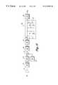
- FIG. 3is a block diagram illustrative of conventional digital ECG signal measuring system 10 (FIG. 1 ).
- ECG signal measuring system 10includes a preamplifier 31 , a high pass filter (BPF) 33 , an analog-to-digital converter (ADC) 35 and a second HPF 37 .
- BPFhigh pass filter
- ADCanalog-to-digital converter
- HPF 37second HPF 37
- ECG signal measuring system 10includes an anti-aliasing filter (not shown) configured to filter out frequency components of the input ECG signal above one-half of the sample rate of ADC 35 .
- the passband of HPF 33is set at about 0.03 Hz, while the passband of HPF 37 is set at about 0.02 Hz. This gives a passband with a lower edge of 0.05 Hz. This performance is consistent with industry standards for diagnostic quality ECG systems (AAMI EC-11). Unfortunately, the baseline wander signal has frequency components above 0.05 Hz. Thus, in this example, HPF 33 passes the baseline wander signal along with the ECG input signal to cause the saturation problem described above.
- an ECG signal measuring systemhaving a relatively large effective dynamic range and high resolution is provided.
- low frequency compression/enhancement techniquesare combined with dither techniques to effectively increase the dynamic range while maintaining resolution. This aspect of the present invention is achieved without increasing the number of bits of the ADC.
- the systemincludes a HPF, an ADC, a decimation filter (DF), and a compensation filter (CF).
- the HPFreceives an input signal (i.e., baseline wander combined with ECG input signal) and attenuates the low frequency components of the input signal. Unlike conventional systems, the HPF serves to attenuate the bias current signal so that the sampled signal remains within the dynamic range of the system. In one embodiment, the HPF attenuates frequency components that are within the frequency bandwidth of the desired ECG output signal.
- the ADCthen oversamples the output signal of the HPF.
- the DFreceives the output samples of the ADC and generates output samples at rate that is at least twice the maximum frequency of the desired ECG output signal.
- the CFthen amplifies the low frequency end of the DF output samples.
- the gain and cutoff frequency of the CFare, ideally, set to exactly offset the HPF's attenuation of those low frequency components of the input signal below the cutoff frequency of the HPF and above the minimum frequency of the desired ECG output signal.
- dither techniquesare used, in effect, to exchange sample rate for resolution.
- system noisenoise inherent in the system due to imperfections in the components, thermal noise, etc.
- the ECG output signalremains within the dynamic range of the system with the desired resolution, which allows the system to display an accurate ECG significantly faster than conventional systems.
- FIG. 1is a diagram illustrative of a typical ECG signal measuring system.
- FIG. 2is a graph illustrative of an ECG generated by a conventional ECG signal measuring system in applying electrodes to a patient.
- FIG. 3is a block diagram illustrative of a conventional digital ECG signal measuring system.
- FIG. 4is a block diagram illustrative of a digital ECG signal measuring system according to one embodiment of the present invention.
- FIG. 5is a graph illustrative of the frequency response of the high pass filter depicted in FIG. 4, according to one embodiment of the present invention.
- FIG. 6is a graph illustrative of the frequency response of the compensation filter depicted in FIG. 4, according to one embodiment of the present invention.
- FIG. 7is a graph illustrative of the frequency response of the system depicted in FIG. 4, according to one embodiment of the present invention.
- FIG. 8is a block diagram illustrative of a digital ECG signal measuring system, according to another embodiment of the present invention.
- FIG. 9is a graph illustrative of the ECG waveforms generated by the ECG signal measuring system of FIG. 9 .
- FIG. 10a graph illustrative of the waveforms ECG generated by the ECG signal measuring system of FIG. 9 with a greater high pass filter comer frequency.
- FIG. 4is a block diagram illustrative of a digital ECG signal measuring system 40 , according to one embodiment of the present invention.
- ECG signal measuring system 40includes preamplifier 31 , a HPF 42 , an anti-aliasing filter (AAF) 48 , ADC 35 , a decimation filter (DF) 44 , and a compensation filter (CF) 46 .
- preamplifier 31a HPF 42
- AAFanti-aliasing filter
- ADC 35ADC 35
- DFdecimation filter
- CFcompensation filter
- ECG measuring system 40is interconnected as follows.
- Preamplifier 31is connected to receive the combined input signal via electrodes 15 and 16 (FIG. 1 ).
- Anti-aliasing filter(typically a LPF having a cutoff frequency less than one half of the sampling rate of the ADC) receives the output signal of preamplifier 31 .
- anti-aliasing filter 48can be placed anywhere in the signal processing flow before ADC 35 .
- HPF 42is connected to receive the output signal of anti-aliasing filter 48 .
- HPF 42has a cutoff frequency of about 0.689 Hz, which is well into the AAMI specified ECG frequency bands (e.g., diagnostic and monitor).
- the frequency response of HPF 42is illustrated in FIG. 5 .
- anti-aliasing filter 48 and HPF 42are respectively implemented in hardware as a 3rd order Butterworth analog filter and a first order analog filter.
- ADC 35is connected to receive the output signal of HPF 42 .
- ADC 35is implemented using a twelve-bit ADC, such as, for example, a model AD7892 available from Analog Devices, Norwood, MA, with a 5 ksps (kilo samples-per-second) sampling rate on each of a large number of sequentially selected channels.
- twelve-bit ADC 35will output a digital output signal with 5 ⁇ V resolution (i.e., a uniform 5 ⁇ V step size).
- DF 44is connected to receive the output samples from ADC 35 .
- DF 44is a implemented as a 61-tap low-pass finite impulse response (FIR) filter implemented in software.
- FIRfinite impulse response
- DF 44computes a weighted running average of the ADC output samples, filters out the frequency components above 150 Hz, and outputs a 0.5 ksps data stream.
- the decimationis performed by shifting the 5 ksps weighted running average samples into a shift register and selecting every tenth sample shifted out of the shift register to serve as the DF output data stream.
- CF 46is connected to receive the output data stream from DF 44 .
- CF 46is implemented in software as a low pass digital filter with amplification or scaling of the output data stream.
- the transfer function of CF 46has a pole equal to the lower frequency boundary of the desired ECG output signal bandwidth (e.g., 0.05 Hz) and has a zero equal to the pole of HPF 42 .
- the frequency response of CF 46is illustrated in FIG. 6 . Consequently, the frequency response of HPF 42 cascaded with CF 46 is equivalent to a LPF having a pole at the lower frequency boundary of the desired ECG output signal bandwidth as illustrated in FIG. 7 .
- ECG signal measuring system 40operates as follows.
- Preamplifier 31receives the combined input signal from electrodes 15 and 16 (FIG. 1 ).
- the combined input signalhas been filtered through AAF 48 .
- HPF 42then filters the amplified combined input signal outputted by preamplifier 31 .
- HPF 42filters out frequency components of the amplified combined input signal below 0.689 Hz.
- H HPF ⁇ ( ⁇ )s ( s + a ) ( 1 )
- H HPF ( ⁇ )is the frequency response of HPF 42 and the variable “a” is the cutoff frequency of HPF 42 in radians.
- ais set to a frequency to attenuate the aforementioned baseline wander signal to prevent saturation of ADC 35 .
- “a”is equal to about 2(0.689) ⁇ .
- AAMIcurrent industry
- “a”is greater than the required lower frequency boundary of the ECG output signal. Consequently, at this point of the signal processing, preventing saturation of ADC 35 comes at the cost of undesirably attenuating the lower frequency portion of the desired ECG output signal.
- ADC 35then samples the output signal from HPF 42 .
- ADC 35samples at a rate of about 5 ksps, which is significantly greater than twice the maximum frequency boundary of the desired ECG signal band. Because HPF 42 attenuates the baseline wander signal, the signal received by ADC 35 has a dynamic range no greater than 20 mV, thereby preventing saturation of ADC 35 .
- DF 44then, as described above, low pass filters and reduces the sampling rate of the digital signal generated by ADC 35 to about 0.5 ksps.
- CF 46then, as described above, filters the output data stream from DF 44 to compensate for the attenuation of the ECG signal frequency components below the cutoff frequency of HPF 42 and above the minimum frequency boundary of the desired ECG signal band.
- This frequency bandis referred to herein as the low-end band.
- CF 46provides a gain that is the inverse of the attenuation of the low-end band, which in this case is between 0.05 Hz and 0.689 Hz.
- H CF ⁇ ( ⁇ )( s + a ) ( s + b ) ( 2 )
- H CF ( ⁇ )is the frequency response of CF 46
- variable “b”is the desired low frequency boundary in radians of the ECG output signal
- variable “a”is as defined above in definition (1).
- H sys ( ⁇ )is the frequency response of HPF 42 cascaded with CF 46
- the variable “b”is as defined above in definition (2). It might appear that this compensation by CF 46 degrades the resolution of the system because the scaling of the low-end band also scales the step size. For example, if CF 46 amplifies a certain portion of the low-end band by ten, then the resolution of that portion would appear to be 25 ⁇ V. However, the inventors of the present invention have observed that the essentially random system or thermal noise injected into the combined input signal before ADC 35 has an average level greater than the step size or resolution of ADC 35 .
- the system noiseis, in effect, a dither signal that improves resolution by modulating some of the quantization error outside the frequency band of interest.
- dither techniquescan be used to improve resolution below the least significant bit (e.g., see Vanderkooy and Lipshitz, “Resolution Below the Least Significant Bit it Digital Systems with Dither,” J. Audio Eng. Soc., Vol. 32, No. 3, Mar., 1984, pp. 106-112).
- the output data stream of CF 48is then displayed in analog form using conventional circuitry.
- oversamplingprovides about a half bit of increased resolution for each doubling of the sampling frequency.
- oversampling alonewould require an oversample ratio of about 256, resulting in a minimum sample rate of about 76.8 ksps to achieve four-bit resolution improvement.
- the oversampling ratio required to achieve the desired resolutionis more strongly dependent on variable “b” rather than the upper frequency boundary of the desired ECG output signal.
- the desired resolutioncan be achieved by ensuring that the oversampling ratio is at least equal to: 1 + a 2 b ⁇ ⁇ upper ( 4 )
- ⁇ upperrepresents the upper frequency boundary in radians of the desired ECG output signal. This ensures that the quantization noise power is equivalent to that of a system which does not have the low-end frequency compensation.
- a minimum oversample ratio of about 1.06is required, resulting in minimum sample rate of about 0.318 ksps.
- the 0.5 ksps data stream provided by DF 44exceeds the required sample rate.
- a higher frequency “a”is required to maintain the desired dynamic range.
- the oversampling rateis increased. For example with a HPF frequency of 5.0 Hz, the oversampling rate is calculated to be 4.33, resulting in a minimum sample rate of about 2.15 kHz.
- FIG. 8is a block diagram illustrative of a digital ECG signal measuring system 90 , according to another embodiment of the present invention.
- ECG measuring system 90is similar to ECG signal measuring system 40 (FIG. 4) except that ECG signal measuring system 90 shows the anti-aliasing filter as a LPF 91 , and includes a dither generator (DG) 92 , a hardware summer or combiner 93 and a LPF 94 .
- DG 92can be implemented with any suitable conventional signal generator.
- CF 46is implemented in software with a standard biquad digital filter which utilizes summers, delays and multipliers.
- ECG signal measuring system 90is interconnected as follows.
- Preamplifier 31is connected to receive the combined signal.
- LPF 91functioning as an AAF, is connected to received the output signal from preamplifier 31 and provide its filtered output signal to HPF 42 .
- Combiner 93is connected to sum the output signal from HPF 42 and DG 92 .
- ADC 35is connected to receive the output signal from combiner 93 and provide its output samples to DF 44 .
- CF 46is connected to receive the data stream from DF 44 . CF 46 then provides its output data stream to LPF 94 .
- the output data stream of LPF 94is then processed by conventional circuitry (not shown) to generate the ECG.
- This embodiment of CF 46is a standard two tap IIR filter with a Direct Form I structure, efficiently implemented in software.
- the transfer function of this filteris equivalent to that of definition (2).
- Another advantage of the embodiment of CF 46is that the effective pole and zero of CF 46 can be easily changed “on-the-fly” by modifying calculation coefficients without inducing transients in the output of the filter. This allows operation of a fast restore function for baseline initialization after external transient events such as a defibrillation pulse.
- ECG signal measuring system 90operates essentially as described above for ECG signal measuring system 40 (FIG. 4) except that DG 92 adds a predetermined dither signal (e.g., a triangular wave with varying between lone half of the step size of ADC 35 ) instead of relying on system noise.
- a predetermined dither signale.g., a triangular wave with varying between lone half of the step size of ADC 35
- This embodimentmay be advantageously used in applications in which the system noise is small relative to the step size of the ADC.
- the dither signalcan be used to shift the quantization noise out of the frequency range of interest.
- LPF 94is used to filter out the repeated or harmonic spectrums caused by the operation of the digitization process on the dithered signal.
- DF 44 and CF 46does not change the system response. Changing the order of processing in this manner would, however, increase the complexity and computing burden of the compensation filter by the ratio of the decimation.
- FIG. 9shows the waveforms generated by a simulation of ECG signal measuring system 90 .
- the input, or raw ECGis shown as sampled at 5 ksps as a waveform 80 .
- the output signal generated from HPF 42set in this example at 0.689 Hz is shown as a waveform 81 .
- Waveform 81has a significant droop in slow moving parts of the waveform as is expected from a HPF with corner frequency in the band of interest. Decimation is accomplished in DF 44 which provides 150 Hz LPF at 500 sps shown as a waveform 82 .
- the output signal generated from CF 46shown as a waveform 83 , is clearly nearly identical to the raw input waveform 80 , maintaining the fidelity required for diagnostic interpretation of the ECG signals.
- FIG. 10shows the same waveforms as FIG. 9, but with HPF 42 and matching CF 44 comer frequencies set to 5.3 Hz. This results in even greater droop in intermediate waveforms 86 and 87 , the output signals generated from HPF 42 and DF 44 respectively.
- the output signal generated from CF 46shown as a waveform 88 has the same fidelity as the output waveform 83 of CF 46 , also clearly nearly identical to the raw input waveform 80 , maintaining the fidelity required for diagnostic interpretation of the ECG signals.
Landscapes
- Health & Medical Sciences (AREA)
- Life Sciences & Earth Sciences (AREA)
- Public Health (AREA)
- Heart & Thoracic Surgery (AREA)
- Engineering & Computer Science (AREA)
- Biomedical Technology (AREA)
- Veterinary Medicine (AREA)
- Animal Behavior & Ethology (AREA)
- General Health & Medical Sciences (AREA)
- Cardiology (AREA)
- Nuclear Medicine, Radiotherapy & Molecular Imaging (AREA)
- Radiology & Medical Imaging (AREA)
- Physics & Mathematics (AREA)
- Biophysics (AREA)
- Pathology (AREA)
- Medical Informatics (AREA)
- Molecular Biology (AREA)
- Surgery (AREA)
- Measurement And Recording Of Electrical Phenomena And Electrical Characteristics Of The Living Body (AREA)
- Analogue/Digital Conversion (AREA)
Abstract
Description


Claims (25)
Priority Applications (3)
| Application Number | Priority Date | Filing Date | Title |
|---|---|---|---|
| US09/232,044US6249696B1 (en) | 1999-01-15 | 1999-01-15 | Method and apparatus for increasing the low frequency dynamic range of a digital ECG measuring system |
| PCT/US2000/000585WO2000041621A1 (en) | 1999-01-15 | 2000-01-10 | Electrocardiograph having large low frequency dynamic range |
| US09/713,455US6317625B1 (en) | 1999-01-15 | 2000-11-15 | Method and apparatus for increasing the low frequency dynamic range of a system for measuring physiological signals with an implantable medical device |
Applications Claiming Priority (1)
| Application Number | Priority Date | Filing Date | Title |
|---|---|---|---|
| US09/232,044US6249696B1 (en) | 1999-01-15 | 1999-01-15 | Method and apparatus for increasing the low frequency dynamic range of a digital ECG measuring system |
Related Child Applications (1)
| Application Number | Title | Priority Date | Filing Date |
|---|---|---|---|
| US09/713,455Continuation-In-PartUS6317625B1 (en) | 1999-01-15 | 2000-11-15 | Method and apparatus for increasing the low frequency dynamic range of a system for measuring physiological signals with an implantable medical device |
Publications (1)
| Publication Number | Publication Date |
|---|---|
| US6249696B1true US6249696B1 (en) | 2001-06-19 |
Family
ID=22871650
Family Applications (2)
| Application Number | Title | Priority Date | Filing Date |
|---|---|---|---|
| US09/232,044Expired - LifetimeUS6249696B1 (en) | 1999-01-15 | 1999-01-15 | Method and apparatus for increasing the low frequency dynamic range of a digital ECG measuring system |
| US09/713,455Expired - Fee RelatedUS6317625B1 (en) | 1999-01-15 | 2000-11-15 | Method and apparatus for increasing the low frequency dynamic range of a system for measuring physiological signals with an implantable medical device |
Family Applications After (1)
| Application Number | Title | Priority Date | Filing Date |
|---|---|---|---|
| US09/713,455Expired - Fee RelatedUS6317625B1 (en) | 1999-01-15 | 2000-11-15 | Method and apparatus for increasing the low frequency dynamic range of a system for measuring physiological signals with an implantable medical device |
Country Status (2)
| Country | Link |
|---|---|
| US (2) | US6249696B1 (en) |
| WO (1) | WO2000041621A1 (en) |
Cited By (43)
| Publication number | Priority date | Publication date | Assignee | Title |
|---|---|---|---|---|
| US20060119492A1 (en)* | 2004-12-03 | 2006-06-08 | Samsung Electronics Co., Ltd. | Apparatus and method for performing dithering in communication system using orthogonal frequency division multiplexing scheme |
| US20070078353A1 (en)* | 2005-10-04 | 2007-04-05 | Welch Allyn, Inc. | Method and apparatus for removing baseline wander from an ECG signal |
| US8319553B1 (en) | 2011-08-02 | 2012-11-27 | Analog Devices, Inc. | Apparatus and methods for biasing amplifiers |
| US8390374B2 (en) | 2011-01-25 | 2013-03-05 | Analog Devices, Inc. | Apparatus and method for amplification with high front-end gain in the presence of large DC offsets |
| US8432222B2 (en) | 2011-09-15 | 2013-04-30 | Analog Devices, Inc. | Apparatus and methods for electronic amplification |
| US8552788B2 (en) | 2011-09-15 | 2013-10-08 | Analog Devices, Inc. | Apparatus and methods for adaptive common-mode level shifting |
| KR20150081666A (en)* | 2014-01-06 | 2015-07-15 | 삼성전자주식회사 | Method and apparatus of detecting interference signal for low power envelope detector |
| US20170209064A1 (en)* | 2013-09-25 | 2017-07-27 | Bardy Diagnostics, Inc. | Ambulatory Electrocardiography Monitor Recorder Optimized For Internal Signal Processing |
| US9901274B2 (en) | 2013-09-25 | 2018-02-27 | Bardy Diagnostics, Inc. | Electrocardiography patch |
| US9955911B2 (en) | 2013-09-25 | 2018-05-01 | Bardy Diagnostics, Inc. | Electrocardiography and respiratory monitor recorder |
| US9955885B2 (en) | 2013-09-25 | 2018-05-01 | Bardy Diagnostics, Inc. | System and method for physiological data processing and delivery |
| US10004415B2 (en) | 2013-09-25 | 2018-06-26 | Bardy Diagnostics, Inc. | Extended wear electrocardiography patch |
| US10045709B2 (en) | 2013-09-25 | 2018-08-14 | Bardy Diagnostics, Inc. | System and method for facilitating a cardiac rhythm disorder diagnosis with the aid of a digital computer |
| US10111601B2 (en) | 2013-09-25 | 2018-10-30 | Bardy Diagnostics, Inc. | Extended wear electrocardiography monitor optimized for capturing low amplitude cardiac action potential propagation |
| US10123703B2 (en) | 2015-10-05 | 2018-11-13 | Bardy Diagnostics, Inc. | Health monitoring apparatus with wireless capabilities for initiating a patient treatment with the aid of a digital computer |
| US10154793B2 (en) | 2013-09-25 | 2018-12-18 | Bardy Diagnostics, Inc. | Extended wear electrocardiography patch with wire contact surfaces |
| US10165946B2 (en) | 2013-09-25 | 2019-01-01 | Bardy Diagnostics, Inc. | Computer-implemented system and method for providing a personal mobile device-triggered medical intervention |
| US10172534B2 (en) | 2013-09-25 | 2019-01-08 | Bardy Diagnostics, Inc. | Remote interfacing electrocardiography patch |
| US10251576B2 (en) | 2013-09-25 | 2019-04-09 | Bardy Diagnostics, Inc. | System and method for ECG data classification for use in facilitating diagnosis of cardiac rhythm disorders with the aid of a digital computer |
| US10251575B2 (en) | 2013-09-25 | 2019-04-09 | Bardy Diagnostics, Inc. | Wearable electrocardiography and physiology monitoring ensemble |
| US10264992B2 (en) | 2013-09-25 | 2019-04-23 | Bardy Diagnostics, Inc. | Extended wear sewn electrode electrocardiography monitor |
| US10398334B2 (en) | 2013-09-25 | 2019-09-03 | Bardy Diagnostics, Inc. | Self-authenticating electrocardiography monitoring circuit |
| US10433751B2 (en) | 2013-09-25 | 2019-10-08 | Bardy Diagnostics, Inc. | System and method for facilitating a cardiac rhythm disorder diagnosis based on subcutaneous cardiac monitoring data |
| US10433748B2 (en) | 2013-09-25 | 2019-10-08 | Bardy Diagnostics, Inc. | Extended wear electrocardiography and physiological sensor monitor |
| US10463269B2 (en) | 2013-09-25 | 2019-11-05 | Bardy Diagnostics, Inc. | System and method for machine-learning-based atrial fibrillation detection |
| US10499812B2 (en) | 2013-09-25 | 2019-12-10 | Bardy Diagnostics, Inc. | System and method for applying a uniform dynamic gain over cardiac data with the aid of a digital computer |
| US10624552B2 (en) | 2013-09-25 | 2020-04-21 | Bardy Diagnostics, Inc. | Method for constructing physiological electrode assembly with integrated flexile wire components |
| US10624551B2 (en) | 2013-09-25 | 2020-04-21 | Bardy Diagnostics, Inc. | Insertable cardiac monitor for use in performing long term electrocardiographic monitoring |
| US10667711B1 (en) | 2013-09-25 | 2020-06-02 | Bardy Diagnostics, Inc. | Contact-activated extended wear electrocardiography and physiological sensor monitor recorder |
| US10736529B2 (en) | 2013-09-25 | 2020-08-11 | Bardy Diagnostics, Inc. | Subcutaneous insertable electrocardiography monitor |
| US10736531B2 (en) | 2013-09-25 | 2020-08-11 | Bardy Diagnostics, Inc. | Subcutaneous insertable cardiac monitor optimized for long term, low amplitude electrocardiographic data collection |
| US10799137B2 (en) | 2013-09-25 | 2020-10-13 | Bardy Diagnostics, Inc. | System and method for facilitating a cardiac rhythm disorder diagnosis with the aid of a digital computer |
| US10806360B2 (en) | 2013-09-25 | 2020-10-20 | Bardy Diagnostics, Inc. | Extended wear ambulatory electrocardiography and physiological sensor monitor |
| US10820801B2 (en) | 2013-09-25 | 2020-11-03 | Bardy Diagnostics, Inc. | Electrocardiography monitor configured for self-optimizing ECG data compression |
| US10888239B2 (en) | 2013-09-25 | 2021-01-12 | Bardy Diagnostics, Inc. | Remote interfacing electrocardiography patch |
| US11096579B2 (en) | 2019-07-03 | 2021-08-24 | Bardy Diagnostics, Inc. | System and method for remote ECG data streaming in real-time |
| US11109790B2 (en)* | 2015-11-18 | 2021-09-07 | Samsung Electronics Co., Ltd. | Patch including an external floating high-pass filter and an electrocardiograph (ECG) patch including the same |
| US11116451B2 (en) | 2019-07-03 | 2021-09-14 | Bardy Diagnostics, Inc. | Subcutaneous P-wave centric insertable cardiac monitor with energy harvesting capabilities |
| US11213237B2 (en) | 2013-09-25 | 2022-01-04 | Bardy Diagnostics, Inc. | System and method for secure cloud-based physiological data processing and delivery |
| US11324441B2 (en) | 2013-09-25 | 2022-05-10 | Bardy Diagnostics, Inc. | Electrocardiography and respiratory monitor |
| US11678830B2 (en) | 2017-12-05 | 2023-06-20 | Bardy Diagnostics, Inc. | Noise-separating cardiac monitor |
| US11696681B2 (en) | 2019-07-03 | 2023-07-11 | Bardy Diagnostics Inc. | Configurable hardware platform for physiological monitoring of a living body |
| US11723575B2 (en) | 2013-09-25 | 2023-08-15 | Bardy Diagnostics, Inc. | Electrocardiography patch |
Families Citing this family (36)
| Publication number | Priority date | Publication date | Assignee | Title |
|---|---|---|---|---|
| US6658283B1 (en) | 2001-09-25 | 2003-12-02 | Pacesetter, Inc. | Implantable cardiac stimulation device, system and method which provides an electrogram signal having the appearance of a surface electrocardiogram |
| US7613508B2 (en)* | 2001-09-25 | 2009-11-03 | Pacesetter, Inc. | Implantable cardiac stimulation device, system and method which provides an electrogram signal facilitating measurement of slow-changing electrogram features |
| US6865420B1 (en) | 2002-01-14 | 2005-03-08 | Pacesetter, Inc. | Cardiac stimulation device for optimizing cardiac output with myocardial ischemia protection |
| US7120484B2 (en)* | 2002-01-14 | 2006-10-10 | Medtronic, Inc. | Methods and apparatus for filtering EGM signals detected by an implantable medical device |
| DE102004021520B4 (en)* | 2004-05-03 | 2008-07-03 | Sattler Ag | Coated, water vapor permeable and fungus resistant fabrics |
| ES2247943B1 (en)* | 2004-08-27 | 2007-04-01 | Gem-Med S.L. | METHOD FOR PROCESSING CARDIOELECTRIC SIGNS AND CORRESPONDING DEVICE. |
| US20060229525A1 (en)* | 2005-04-08 | 2006-10-12 | Exelys, Llc | Portable cardiac monitor including pulsed power operation |
| US7474914B2 (en)* | 2005-04-08 | 2009-01-06 | Exelys, Llc | Portable cardiac monitor including a range limiter |
| US7361188B2 (en)* | 2005-04-08 | 2008-04-22 | Exelys, Llc | Portable cardiac monitor |
| US20060229522A1 (en)* | 2005-04-08 | 2006-10-12 | Exelys, Llc | Portable cardiac monitor including RF communication |
| US8180442B2 (en)* | 2007-12-14 | 2012-05-15 | Greatbatch Ltd. | Deriving patient activity information from sensed body electrical information |
| US9026370B2 (en) | 2007-12-18 | 2015-05-05 | Hospira, Inc. | User interface improvements for medical devices |
| US8915866B2 (en) | 2008-01-18 | 2014-12-23 | Warsaw Orthopedic, Inc. | Implantable sensor and associated methods |
| AU2012299169B2 (en) | 2011-08-19 | 2017-08-24 | Icu Medical, Inc. | Systems and methods for a graphical interface including a graphical representation of medical data |
| US10022498B2 (en) | 2011-12-16 | 2018-07-17 | Icu Medical, Inc. | System for monitoring and delivering medication to a patient and method of using the same to minimize the risks associated with automated therapy |
| JP6306566B2 (en) | 2012-03-30 | 2018-04-04 | アイシーユー・メディカル・インコーポレーテッド | Air detection system and method for detecting air in an infusion system pump |
| AU2013296555B2 (en) | 2012-07-31 | 2017-10-19 | Icu Medical, Inc. | Patient care system for critical medications |
| AU2014268355B2 (en) | 2013-05-24 | 2018-06-14 | Icu Medical, Inc. | Multi-sensor infusion system for detecting air or an occlusion in the infusion system |
| WO2014194065A1 (en) | 2013-05-29 | 2014-12-04 | Hospira, Inc. | Infusion system and method of use which prevents over-saturation of an analog-to-digital converter |
| US10166328B2 (en) | 2013-05-29 | 2019-01-01 | Icu Medical, Inc. | Infusion system which utilizes one or more sensors and additional information to make an air determination regarding the infusion system |
| EP3110474B1 (en) | 2014-02-28 | 2019-12-18 | ICU Medical, Inc. | Infusion system and method which utilizes dual wavelength optical air-in-line detection |
| US11344673B2 (en) | 2014-05-29 | 2022-05-31 | Icu Medical, Inc. | Infusion system and pump with configurable closed loop delivery rate catch-up |
| CN103989470B (en)* | 2014-05-30 | 2016-01-27 | 中国科学院微电子研究所 | Electrocardiosignal acquisition equipment, dynamic electrocardiograph, system and signal transmission method |
| US11344668B2 (en) | 2014-12-19 | 2022-05-31 | Icu Medical, Inc. | Infusion system with concurrent TPN/insulin infusion |
| US10850024B2 (en) | 2015-03-02 | 2020-12-01 | Icu Medical, Inc. | Infusion system, device, and method having advanced infusion features |
| CA3023658C (en) | 2016-05-13 | 2023-03-07 | Icu Medical, Inc. | Infusion pump system and method with common line auto flush |
| WO2017214441A1 (en) | 2016-06-10 | 2017-12-14 | Icu Medical, Inc. | Acoustic flow sensor for continuous medication flow measurements and feedback control of infusion |
| US10089055B1 (en) | 2017-12-27 | 2018-10-02 | Icu Medical, Inc. | Synchronized display of screen content on networked devices |
| CN119423777A (en) | 2018-01-23 | 2025-02-14 | 程杰 | Precise localization of cardiac arrhythmias using internal electrocardiogram (ECG) signals sensed and stored by an implantable device |
| RU2723222C1 (en)* | 2019-11-18 | 2020-06-09 | Евгений Владимирович Круглов | Electric cardiosignal processing unit with analogue-digital filtration |
| US11278671B2 (en) | 2019-12-04 | 2022-03-22 | Icu Medical, Inc. | Infusion pump with safety sequence keypad |
| CA3189781A1 (en) | 2020-07-21 | 2022-01-27 | Icu Medical, Inc. | Fluid transfer devices and methods of use |
| US11135360B1 (en) | 2020-12-07 | 2021-10-05 | Icu Medical, Inc. | Concurrent infusion with common line auto flush |
| USD1091564S1 (en) | 2021-10-13 | 2025-09-02 | Icu Medical, Inc. | Display screen or portion thereof with graphical user interface for a medical device |
| CA3241894A1 (en) | 2021-12-10 | 2023-06-15 | Icu Medical, Inc. | Medical fluid compounding systems with coordinated flow control |
| US11707233B1 (en) | 2022-12-16 | 2023-07-25 | Wisear | Simultaneous sub-Nyquist acquisition of a plurality of bioelectric signals |
Citations (19)
| Publication number | Priority date | Publication date | Assignee | Title |
|---|---|---|---|---|
| US3569852A (en) | 1969-01-23 | 1971-03-09 | American Optical Corp | Frequency selective variable gain amplifier |
| US3868567A (en)* | 1973-11-26 | 1975-02-25 | Univ Washington | Measurement of ST depression of electrocardiograms |
| US4147162A (en) | 1977-06-10 | 1979-04-03 | Hewlett-Packard Company | Defibrillator monitor baseline control |
| US4153049A (en) | 1977-11-16 | 1979-05-08 | Hewlett-Packard Company | Apparatus for maintaining signals within a given amplitude range |
| US4194511A (en) | 1978-08-18 | 1980-03-25 | Electronics For Medicine, Inc. | Detecting capacitively coupled ECG baseline shift |
| US4479922A (en) | 1983-04-04 | 1984-10-30 | At&T Technologies, Inc. | Solvent treatment in the separation of palladium and/or gold from other platinum group and base metals |
| US4494551A (en) | 1982-11-12 | 1985-01-22 | Medicomp, Inc. | Alterable frequency response electrocardiographic amplifier |
| US4800364A (en) | 1985-07-15 | 1989-01-24 | Mortara David W | Analog-to-digital converter utilizing vernier techniques |
| US5042026A (en) | 1987-03-03 | 1991-08-20 | Nec Corporation | Circuit for cancelling whole or part of a waveform using nonrecursive and recursive filters |
| US5215098A (en)* | 1991-08-12 | 1993-06-01 | Telectronics Pacing Systems, Inc. | Data compression of cardiac electrical signals using scanning correlation and temporal data compression |
| US5297557A (en) | 1992-10-14 | 1994-03-29 | Del Mar Avionics | Stress test system with bidirectional filter |
| US5318036A (en) | 1992-03-17 | 1994-06-07 | Hewlett-Packard Company | Method and apparatus for removing baseline wander from an ECG signal |
| US5357969A (en) | 1993-03-18 | 1994-10-25 | Hewlett-Packard Company | Method and apparatus for accurately displaying an ECG signal |
| US5433208A (en) | 1991-03-01 | 1995-07-18 | Siemens Aktiengesellschaft | Device for filtering out baseline fluctuations from physiological measurement signals |
| US5532951A (en) | 1993-07-16 | 1996-07-02 | Siemens-Elema Ab | Device for eliminating ringing in filtered ECG signals |
| US5601089A (en) | 1993-03-12 | 1997-02-11 | Hewlett-Packard Company | Method and apparatus for boosting the amplitude of ECG signals within a predetermined frequency range |
| US5762068A (en) | 1995-11-27 | 1998-06-09 | Quinton Instrument Company | ECG filter and slew rate limiter for filtering an ECG signal |
| US5772603A (en) | 1993-07-16 | 1998-06-30 | Siemens-Elema Ab | Device for filtering ECG signals |
| US5954660A (en)* | 1997-01-07 | 1999-09-21 | Ela Medical, S.A. | Apparatus for filtering cardiac signals |
Family Cites Families (4)
| Publication number | Priority date | Publication date | Assignee | Title |
|---|---|---|---|---|
| US1357098A (en) | 1919-10-18 | 1920-10-26 | Frank L Kryder | Cord tire |
| US4556063A (en) | 1980-10-07 | 1985-12-03 | Medtronic, Inc. | Telemetry system for a medical device |
| WO1992017240A1 (en) | 1991-04-05 | 1992-10-15 | Medtronic, Inc. | Subcutaneous multi-electrode sensing system |
| US6128526A (en) | 1999-03-29 | 2000-10-03 | Medtronic, Inc. | Method for ischemia detection and apparatus for using same |
- 1999
- 1999-01-15USUS09/232,044patent/US6249696B1/ennot_activeExpired - Lifetime
- 2000
- 2000-01-10WOPCT/US2000/000585patent/WO2000041621A1/enactiveSearch and Examination
- 2000-11-15USUS09/713,455patent/US6317625B1/ennot_activeExpired - Fee Related
Patent Citations (20)
| Publication number | Priority date | Publication date | Assignee | Title |
|---|---|---|---|---|
| US3569852A (en) | 1969-01-23 | 1971-03-09 | American Optical Corp | Frequency selective variable gain amplifier |
| US3868567A (en)* | 1973-11-26 | 1975-02-25 | Univ Washington | Measurement of ST depression of electrocardiograms |
| US4147162A (en) | 1977-06-10 | 1979-04-03 | Hewlett-Packard Company | Defibrillator monitor baseline control |
| US4153049A (en) | 1977-11-16 | 1979-05-08 | Hewlett-Packard Company | Apparatus for maintaining signals within a given amplitude range |
| US4194511A (en) | 1978-08-18 | 1980-03-25 | Electronics For Medicine, Inc. | Detecting capacitively coupled ECG baseline shift |
| US4494551A (en) | 1982-11-12 | 1985-01-22 | Medicomp, Inc. | Alterable frequency response electrocardiographic amplifier |
| US4479922A (en) | 1983-04-04 | 1984-10-30 | At&T Technologies, Inc. | Solvent treatment in the separation of palladium and/or gold from other platinum group and base metals |
| US4800364A (en) | 1985-07-15 | 1989-01-24 | Mortara David W | Analog-to-digital converter utilizing vernier techniques |
| US5042026A (en) | 1987-03-03 | 1991-08-20 | Nec Corporation | Circuit for cancelling whole or part of a waveform using nonrecursive and recursive filters |
| US5433208A (en) | 1991-03-01 | 1995-07-18 | Siemens Aktiengesellschaft | Device for filtering out baseline fluctuations from physiological measurement signals |
| US5215098A (en)* | 1991-08-12 | 1993-06-01 | Telectronics Pacing Systems, Inc. | Data compression of cardiac electrical signals using scanning correlation and temporal data compression |
| US5318036A (en) | 1992-03-17 | 1994-06-07 | Hewlett-Packard Company | Method and apparatus for removing baseline wander from an ECG signal |
| US5297557A (en) | 1992-10-14 | 1994-03-29 | Del Mar Avionics | Stress test system with bidirectional filter |
| US5402795A (en) | 1992-10-14 | 1995-04-04 | Delmar Avionics | Electrocardiographic baseline filtering and estimation system with bidirectional filter |
| US5601089A (en) | 1993-03-12 | 1997-02-11 | Hewlett-Packard Company | Method and apparatus for boosting the amplitude of ECG signals within a predetermined frequency range |
| US5357969A (en) | 1993-03-18 | 1994-10-25 | Hewlett-Packard Company | Method and apparatus for accurately displaying an ECG signal |
| US5532951A (en) | 1993-07-16 | 1996-07-02 | Siemens-Elema Ab | Device for eliminating ringing in filtered ECG signals |
| US5772603A (en) | 1993-07-16 | 1998-06-30 | Siemens-Elema Ab | Device for filtering ECG signals |
| US5762068A (en) | 1995-11-27 | 1998-06-09 | Quinton Instrument Company | ECG filter and slew rate limiter for filtering an ECG signal |
| US5954660A (en)* | 1997-01-07 | 1999-09-21 | Ela Medical, S.A. | Apparatus for filtering cardiac signals |
Non-Patent Citations (3)
| Title |
|---|
| Leung, S.W., Zhang, Y.T., "Digitization of Electrocardiogram (ECG) Signals Using Delta-Sigma Modulation," Proceedings of the 20th Annual International Conference of the IEEE Engineering in Medicine and Biology Society, vol. 20, No. 4, 1998, pp. 1964-1966. |
| Ruha, A., Kostamovaara, J., Saynajakangas, S., "Micropower Analog Structures for CMOS Heart Rate Indicator," Proceedings of the 32nd Midwest Symposium on Circuits and Systems, Aug. 1989, 1990 IEEE, pp. 689-692. |
| Vanderkooy, John and Lipshitz, Stanley P., J. Audio Eng. Soc., "Resolution Below the Least Significant Bit in Digital Systems with Dither," vol. 32, No. 3, Mar. 1984. |
Cited By (106)
| Publication number | Priority date | Publication date | Assignee | Title |
|---|---|---|---|---|
| US20060119492A1 (en)* | 2004-12-03 | 2006-06-08 | Samsung Electronics Co., Ltd. | Apparatus and method for performing dithering in communication system using orthogonal frequency division multiplexing scheme |
| US7307563B2 (en)* | 2004-12-03 | 2007-12-11 | Samsung Electronics Co., Ltd. | Apparatus and method for performing dithering in communication system using orthogonal frequency division multiplexing scheme |
| US20070078353A1 (en)* | 2005-10-04 | 2007-04-05 | Welch Allyn, Inc. | Method and apparatus for removing baseline wander from an ECG signal |
| US20070078354A1 (en)* | 2005-10-04 | 2007-04-05 | Welch Allyn, Inc. | Method and apparatus for removing baseline wander from an ECG signal |
| US8390374B2 (en) | 2011-01-25 | 2013-03-05 | Analog Devices, Inc. | Apparatus and method for amplification with high front-end gain in the presence of large DC offsets |
| US8319553B1 (en) | 2011-08-02 | 2012-11-27 | Analog Devices, Inc. | Apparatus and methods for biasing amplifiers |
| US8432222B2 (en) | 2011-09-15 | 2013-04-30 | Analog Devices, Inc. | Apparatus and methods for electronic amplification |
| US8552788B2 (en) | 2011-09-15 | 2013-10-08 | Analog Devices, Inc. | Apparatus and methods for adaptive common-mode level shifting |
| US10813568B2 (en) | 2013-09-25 | 2020-10-27 | Bardy Diagnostics, Inc. | System and method for classifier-based atrial fibrillation detection with the aid of a digital computer |
| US10264992B2 (en) | 2013-09-25 | 2019-04-23 | Bardy Diagnostics, Inc. | Extended wear sewn electrode electrocardiography monitor |
| US20170209064A1 (en)* | 2013-09-25 | 2017-07-27 | Bardy Diagnostics, Inc. | Ambulatory Electrocardiography Monitor Recorder Optimized For Internal Signal Processing |
| US9901274B2 (en) | 2013-09-25 | 2018-02-27 | Bardy Diagnostics, Inc. | Electrocardiography patch |
| US9955911B2 (en) | 2013-09-25 | 2018-05-01 | Bardy Diagnostics, Inc. | Electrocardiography and respiratory monitor recorder |
| US9955888B2 (en)* | 2013-09-25 | 2018-05-01 | Bardy Diagnostics, Inc. | Ambulatory electrocardiography monitor recorder optimized for internal signal processing |
| US9955885B2 (en) | 2013-09-25 | 2018-05-01 | Bardy Diagnostics, Inc. | System and method for physiological data processing and delivery |
| US10004415B2 (en) | 2013-09-25 | 2018-06-26 | Bardy Diagnostics, Inc. | Extended wear electrocardiography patch |
| US10045709B2 (en) | 2013-09-25 | 2018-08-14 | Bardy Diagnostics, Inc. | System and method for facilitating a cardiac rhythm disorder diagnosis with the aid of a digital computer |
| US20180249924A1 (en)* | 2013-09-25 | 2018-09-06 | Bardy Diagnostics, Inc. | Monitor recorder optimized for electrocardiographic signal processing |
| US10111601B2 (en) | 2013-09-25 | 2018-10-30 | Bardy Diagnostics, Inc. | Extended wear electrocardiography monitor optimized for capturing low amplitude cardiac action potential propagation |
| US12369828B1 (en) | 2013-09-25 | 2025-07-29 | Bardy Diagnostics, Inc. | Extended wear ambulatory electrocardiogramay monitor |
| US10154793B2 (en) | 2013-09-25 | 2018-12-18 | Bardy Diagnostics, Inc. | Extended wear electrocardiography patch with wire contact surfaces |
| US10165946B2 (en) | 2013-09-25 | 2019-01-01 | Bardy Diagnostics, Inc. | Computer-implemented system and method for providing a personal mobile device-triggered medical intervention |
| US10172534B2 (en) | 2013-09-25 | 2019-01-08 | Bardy Diagnostics, Inc. | Remote interfacing electrocardiography patch |
| US10251576B2 (en) | 2013-09-25 | 2019-04-09 | Bardy Diagnostics, Inc. | System and method for ECG data classification for use in facilitating diagnosis of cardiac rhythm disorders with the aid of a digital computer |
| US10251575B2 (en) | 2013-09-25 | 2019-04-09 | Bardy Diagnostics, Inc. | Wearable electrocardiography and physiology monitoring ensemble |
| US12324672B1 (en) | 2013-09-25 | 2025-06-10 | Bardy Diagnostics, Inc. | Moisture-resistant electrocardiography monitor |
| US10939841B2 (en) | 2013-09-25 | 2021-03-09 | Bardy Diagnostics, Inc. | Wearable electrocardiography and physiology monitoring ensemble |
| US10265015B2 (en) | 2013-09-25 | 2019-04-23 | Bardy Diagnostics, Inc. | Monitor recorder optimized for electrocardiography and respiratory data acquisition and processing |
| US10271756B2 (en)* | 2013-09-25 | 2019-04-30 | Bardy Diagnostics, Inc. | Monitor recorder optimized for electrocardiographic signal processing |
| US10278606B2 (en) | 2013-09-25 | 2019-05-07 | Bardy Diagnostics, Inc. | Ambulatory electrocardiography monitor optimized for capturing low amplitude cardiac action potential propagation |
| US10278603B2 (en) | 2013-09-25 | 2019-05-07 | Bardy Diagnostics, Inc. | System and method for secure physiological data acquisition and storage |
| US12310735B2 (en) | 2013-09-25 | 2025-05-27 | Bardy Diagnostics, Inc. | Extended wear ambulatory electrocardiography monitor |
| US10398334B2 (en) | 2013-09-25 | 2019-09-03 | Bardy Diagnostics, Inc. | Self-authenticating electrocardiography monitoring circuit |
| US10433743B1 (en) | 2013-09-25 | 2019-10-08 | Bardy Diagnostics, Inc. | Method for secure physiological data acquisition and storage |
| US10433751B2 (en) | 2013-09-25 | 2019-10-08 | Bardy Diagnostics, Inc. | System and method for facilitating a cardiac rhythm disorder diagnosis based on subcutaneous cardiac monitoring data |
| US10433748B2 (en) | 2013-09-25 | 2019-10-08 | Bardy Diagnostics, Inc. | Extended wear electrocardiography and physiological sensor monitor |
| US10463269B2 (en) | 2013-09-25 | 2019-11-05 | Bardy Diagnostics, Inc. | System and method for machine-learning-based atrial fibrillation detection |
| US10478083B2 (en) | 2013-09-25 | 2019-11-19 | Bardy Diagnostics, Inc. | Extended wear ambulatory electrocardiography and physiological sensor monitor |
| US10499812B2 (en) | 2013-09-25 | 2019-12-10 | Bardy Diagnostics, Inc. | System and method for applying a uniform dynamic gain over cardiac data with the aid of a digital computer |
| US10561326B2 (en) | 2013-09-25 | 2020-02-18 | Bardy Diagnostics, Inc. | Monitor recorder optimized for electrocardiographic potential processing |
| US10561328B2 (en) | 2013-09-25 | 2020-02-18 | Bardy Diagnostics, Inc. | Multipart electrocardiography monitor optimized for capturing low amplitude cardiac action potential propagation |
| US10602977B2 (en) | 2013-09-25 | 2020-03-31 | Bardy Diagnostics, Inc. | Electrocardiography and respiratory monitor |
| US10888239B2 (en) | 2013-09-25 | 2021-01-12 | Bardy Diagnostics, Inc. | Remote interfacing electrocardiography patch |
| US10624551B2 (en) | 2013-09-25 | 2020-04-21 | Bardy Diagnostics, Inc. | Insertable cardiac monitor for use in performing long term electrocardiographic monitoring |
| US10631748B2 (en) | 2013-09-25 | 2020-04-28 | Bardy Diagnostics, Inc. | Extended wear electrocardiography patch with wire interconnects |
| US10667711B1 (en) | 2013-09-25 | 2020-06-02 | Bardy Diagnostics, Inc. | Contact-activated extended wear electrocardiography and physiological sensor monitor recorder |
| US10736532B2 (en) | 2013-09-25 | 2020-08-11 | Bardy Diagnotics, Inc. | System and method for facilitating a cardiac rhythm disorder diagnosis with the aid of a digital computer |
| US10736529B2 (en) | 2013-09-25 | 2020-08-11 | Bardy Diagnostics, Inc. | Subcutaneous insertable electrocardiography monitor |
| US10736531B2 (en) | 2013-09-25 | 2020-08-11 | Bardy Diagnostics, Inc. | Subcutaneous insertable cardiac monitor optimized for long term, low amplitude electrocardiographic data collection |
| US10799137B2 (en) | 2013-09-25 | 2020-10-13 | Bardy Diagnostics, Inc. | System and method for facilitating a cardiac rhythm disorder diagnosis with the aid of a digital computer |
| US10806360B2 (en) | 2013-09-25 | 2020-10-20 | Bardy Diagnostics, Inc. | Extended wear ambulatory electrocardiography and physiological sensor monitor |
| US10813567B2 (en) | 2013-09-25 | 2020-10-27 | Bardy Diagnostics, Inc. | System and method for composite display of subcutaneous cardiac monitoring data |
| US12303278B1 (en) | 2013-09-25 | 2025-05-20 | Bardy Diagnostics, Inc. | Electrocardiography patch |
| US10820801B2 (en) | 2013-09-25 | 2020-11-03 | Bardy Diagnostics, Inc. | Electrocardiography monitor configured for self-optimizing ECG data compression |
| US10849523B2 (en) | 2013-09-25 | 2020-12-01 | Bardy Diagnostics, Inc. | System and method for ECG data classification for use in facilitating diagnosis of cardiac rhythm disorders |
| US11918364B2 (en) | 2013-09-25 | 2024-03-05 | Bardy Diagnostics, Inc. | Extended wear ambulatory electrocardiography and physiological sensor monitor |
| US10624552B2 (en) | 2013-09-25 | 2020-04-21 | Bardy Diagnostics, Inc. | Method for constructing physiological electrode assembly with integrated flexile wire components |
| US11826151B2 (en) | 2013-09-25 | 2023-11-28 | Bardy Diagnostics, Inc. | System and method for physiological data classification for use in facilitating diagnosis |
| US11647939B2 (en) | 2013-09-25 | 2023-05-16 | Bardy Diagnostics, Inc. | System and method for facilitating a cardiac rhythm disorder diagnosis with the aid of a digital computer |
| US11013446B2 (en) | 2013-09-25 | 2021-05-25 | Bardy Diagnostics, Inc. | System for secure physiological data acquisition and delivery |
| US11051743B2 (en) | 2013-09-25 | 2021-07-06 | Bardy Diagnostics, Inc. | Electrocardiography patch |
| US11051754B2 (en) | 2013-09-25 | 2021-07-06 | Bardy Diagnostics, Inc. | Electrocardiography and respiratory monitor |
| US11793441B2 (en) | 2013-09-25 | 2023-10-24 | Bardy Diagnostics, Inc. | Electrocardiography patch |
| US11103173B2 (en) | 2013-09-25 | 2021-08-31 | Bardy Diagnostics, Inc. | Electrocardiography patch |
| US11786159B2 (en) | 2013-09-25 | 2023-10-17 | Bardy Diagnostics, Inc. | Self-authenticating electrocardiography and physiological sensor monitor |
| US11744513B2 (en) | 2013-09-25 | 2023-09-05 | Bardy Diagnostics, Inc. | Electrocardiography and respiratory monitor |
| US11179087B2 (en) | 2013-09-25 | 2021-11-23 | Bardy Diagnostics, Inc. | System for facilitating a cardiac rhythm disorder diagnosis with the aid of a digital computer |
| US11213237B2 (en) | 2013-09-25 | 2022-01-04 | Bardy Diagnostics, Inc. | System and method for secure cloud-based physiological data processing and delivery |
| US11272872B2 (en) | 2013-09-25 | 2022-03-15 | Bardy Diagnostics, Inc. | Expended wear ambulatory electrocardiography and physiological sensor monitor |
| US11324441B2 (en) | 2013-09-25 | 2022-05-10 | Bardy Diagnostics, Inc. | Electrocardiography and respiratory monitor |
| US11445961B2 (en) | 2013-09-25 | 2022-09-20 | Bardy Diagnostics, Inc. | Self-authenticating electrocardiography and physiological sensor monitor |
| US11445962B2 (en) | 2013-09-25 | 2022-09-20 | Bardy Diagnostics, Inc. | Ambulatory electrocardiography monitor |
| US11445907B2 (en) | 2013-09-25 | 2022-09-20 | Bardy Diagnostics, Inc. | Ambulatory encoding monitor recorder optimized for rescalable encoding and method of use |
| US11445964B2 (en) | 2013-09-25 | 2022-09-20 | Bardy Diagnostics, Inc. | System for electrocardiographic potentials processing and acquisition |
| US11445967B2 (en) | 2013-09-25 | 2022-09-20 | Bardy Diagnostics, Inc. | Electrocardiography patch |
| US11445969B2 (en) | 2013-09-25 | 2022-09-20 | Bardy Diagnostics, Inc. | System and method for event-centered display of subcutaneous cardiac monitoring data |
| US11445908B2 (en) | 2013-09-25 | 2022-09-20 | Bardy Diagnostics, Inc. | Subcutaneous electrocardiography monitor configured for self-optimizing ECG data compression |
| US11445970B2 (en) | 2013-09-25 | 2022-09-20 | Bardy Diagnostics, Inc. | System and method for neural-network-based atrial fibrillation detection with the aid of a digital computer |
| US11445966B2 (en) | 2013-09-25 | 2022-09-20 | Bardy Diagnostics, Inc. | Extended wear electrocardiography and physiological sensor monitor |
| US11445965B2 (en) | 2013-09-25 | 2022-09-20 | Bardy Diagnostics, Inc. | Subcutaneous insertable cardiac monitor optimized for long-term electrocardiographic monitoring |
| US11457852B2 (en) | 2013-09-25 | 2022-10-04 | Bardy Diagnostics, Inc. | Multipart electrocardiography monitor |
| US11647941B2 (en) | 2013-09-25 | 2023-05-16 | Bardy Diagnostics, Inc. | System and method for facilitating a cardiac rhythm disorder diagnosis with the aid of a digital computer |
| US11006883B2 (en) | 2013-09-25 | 2021-05-18 | Bardy Diagnostics, Inc. | Extended wear electrocardiography and physiological sensor monitor |
| US11653869B2 (en) | 2013-09-25 | 2023-05-23 | Bardy Diagnostics, Inc. | Multicomponent electrocardiography monitor |
| US11723575B2 (en) | 2013-09-25 | 2023-08-15 | Bardy Diagnostics, Inc. | Electrocardiography patch |
| US11653868B2 (en) | 2013-09-25 | 2023-05-23 | Bardy Diagnostics, Inc. | Subcutaneous insertable cardiac monitor optimized for electrocardiographic (ECG) signal acquisition |
| US11653870B2 (en) | 2013-09-25 | 2023-05-23 | Bardy Diagnostics, Inc. | System and method for display of subcutaneous cardiac monitoring data |
| US11660035B2 (en) | 2013-09-25 | 2023-05-30 | Bardy Diagnostics, Inc. | Insertable cardiac monitor |
| US11660037B2 (en) | 2013-09-25 | 2023-05-30 | Bardy Diagnostics, Inc. | System for electrocardiographic signal acquisition and processing |
| US11701045B2 (en) | 2013-09-25 | 2023-07-18 | Bardy Diagnostics, Inc. | Expended wear ambulatory electrocardiography monitor |
| US11678832B2 (en) | 2013-09-25 | 2023-06-20 | Bardy Diagnostics, Inc. | System and method for atrial fibrillation detection in non-noise ECG data with the aid of a digital computer |
| US11678799B2 (en) | 2013-09-25 | 2023-06-20 | Bardy Diagnostics, Inc. | Subcutaneous electrocardiography monitor configured for test-based data compression |
| US11701044B2 (en) | 2013-09-25 | 2023-07-18 | Bardy Diagnostics, Inc. | Electrocardiography patch |
| KR20150081666A (en)* | 2014-01-06 | 2015-07-15 | 삼성전자주식회사 | Method and apparatus of detecting interference signal for low power envelope detector |
| US20160308627A1 (en)* | 2014-01-06 | 2016-10-20 | Samsung Electronics Co., Ltd. | Method and device for detecting interference signal from low-power envelope detection receiver |
| US10270545B2 (en)* | 2014-01-06 | 2019-04-23 | Samsung Electronics Co., Ltd. | Method and device for detecting interference signal from low-power envelope detection receiver |
| US10869601B2 (en) | 2015-10-05 | 2020-12-22 | Bardy Diagnostics, Inc. | System and method for patient medical care initiation based on physiological monitoring data with the aid of a digital computer |
| US10390700B2 (en) | 2015-10-05 | 2019-08-27 | Bardy Diagnostics, Inc. | Health monitoring apparatus for initiating a treatment of a patient based on physiological data with the aid of a digital computer |
| US10123703B2 (en) | 2015-10-05 | 2018-11-13 | Bardy Diagnostics, Inc. | Health monitoring apparatus with wireless capabilities for initiating a patient treatment with the aid of a digital computer |
| US11109790B2 (en)* | 2015-11-18 | 2021-09-07 | Samsung Electronics Co., Ltd. | Patch including an external floating high-pass filter and an electrocardiograph (ECG) patch including the same |
| US11678830B2 (en) | 2017-12-05 | 2023-06-20 | Bardy Diagnostics, Inc. | Noise-separating cardiac monitor |
| US11678798B2 (en) | 2019-07-03 | 2023-06-20 | Bardy Diagnostics Inc. | System and method for remote ECG data streaming in real-time |
| US11653880B2 (en) | 2019-07-03 | 2023-05-23 | Bardy Diagnostics, Inc. | System for cardiac monitoring with energy-harvesting-enhanced data transfer capabilities |
| US11116451B2 (en) | 2019-07-03 | 2021-09-14 | Bardy Diagnostics, Inc. | Subcutaneous P-wave centric insertable cardiac monitor with energy harvesting capabilities |
| US11696681B2 (en) | 2019-07-03 | 2023-07-11 | Bardy Diagnostics Inc. | Configurable hardware platform for physiological monitoring of a living body |
| US11096579B2 (en) | 2019-07-03 | 2021-08-24 | Bardy Diagnostics, Inc. | System and method for remote ECG data streaming in real-time |
Also Published As
| Publication number | Publication date |
|---|---|
| WO2000041621A9 (en) | 2002-05-02 |
| WO2000041621A1 (en) | 2000-07-20 |
| US6317625B1 (en) | 2001-11-13 |
Similar Documents
| Publication | Publication Date | Title |
|---|---|---|
| US6249696B1 (en) | Method and apparatus for increasing the low frequency dynamic range of a digital ECG measuring system | |
| EP0634135B1 (en) | Device for filtering ECG signals | |
| US6280391B1 (en) | Method and apparatus for removing baseline wander from an egg signal | |
| US5297557A (en) | Stress test system with bidirectional filter | |
| US5357969A (en) | Method and apparatus for accurately displaying an ECG signal | |
| EP1575426B1 (en) | Method and device for measurement of electrical bioimpedance | |
| US10194815B2 (en) | Variable bandwidth ECG high pass filter | |
| US7783339B2 (en) | Method and system for real-time digital filtering for electrophysiological and hemodynamic amplifers | |
| JPH10229975A (en) | Device for filtering heart rate signal | |
| Gregg et al. | What is inside the electrocardiograph? | |
| Gholam-Hosseini et al. | ECG noise cancellation using digital filters | |
| Verulkar et al. | Filtering techniques for reduction of power line interference in electrocardiogram signals | |
| Chavan et al. | Comparative study of Chebyshev I and Chebyshev II filter used for noise reduction in ECG signal | |
| Kwatra et al. | A new technique for monitoring heart signals-part I: instrumentation design | |
| EP0778002A1 (en) | Heart monitoring system and method with reduced signal acquisition range | |
| Al-Nashash et al. | Noninvasive beat-to-beat detection of ventricular late potentials | |
| Regan et al. | The transducer characteristic of hair cells in the human ear: A possible objective measure | |
| EP3893723B1 (en) | Filtering unit for electrocardiography applications | |
| US20240195445A1 (en) | Method and System for Processing an Analog Signal | |
| Dotsinsky et al. | Fast electrocardiogram amplifier recovery after defibrillation shock | |
| Uma et al. | ECG Noise Removal Using Modified Distributed Arithmetic Based Finite Impulse Response Filter | |
| US20040205424A1 (en) | Differential filter with high common mode rejection ratio | |
| Vityazeva et al. | Accuracy Loss in Multi-Rate Processing of Biomedical Signals | |
| Levkov et al. | Subtraction Method for Powerline Interference Removing from ECG | |
| PARULEKAR et al. | COMPARISON OF FILTER OUTPUTS FOR ECG SIGNALS |
Legal Events
| Date | Code | Title | Description |
|---|---|---|---|
| AS | Assignment | Owner name:PHYSIO-CONTROL CORPORATION, WASHINGTON Free format text:ASSIGNMENT OF ASSIGNORS INTEREST;ASSIGNORS:OLSON, DANA J.;VAN ESS, DAVID W.;REEL/FRAME:009710/0240 Effective date:19990115 | |
| AS | Assignment | Owner name:MEDTRONIC PHYSIO-CONTROL MANUFACTURING CORP., WASH Free format text:ASSIGNMENT OF ASSIGNORS INTEREST;ASSIGNOR:PHYSIO-CONTROL CORPORATION;REEL/FRAME:009914/0994 Effective date:19990401 | |
| STCF | Information on status: patent grant | Free format text:PATENTED CASE | |
| CC | Certificate of correction | ||
| FPAY | Fee payment | Year of fee payment:4 | |
| FPAY | Fee payment | Year of fee payment:8 | |
| AS | Assignment | Owner name:PHYSIO-CONTROL, INC., WASHINGTON Free format text:ASSIGNMENT OF ASSIGNORS INTEREST;ASSIGNOR:MEDTRONIC PHYSIO-CONTROL MANUFACTURING CORP.;REEL/FRAME:027015/0797 Effective date:20111003 | |
| AS | Assignment | Owner name:BANK OF NEW YORK MELLON TRUST COMPANY, N.A., AS *C Free format text:SECURITY AGREEMENT;ASSIGNOR:PHYSIO-CONTROL, INC.;REEL/FRAME:027765/0861 Effective date:20120130 | |
| AS | Assignment | Owner name:CITIBANK, N.A., AS COLLATERAL AGENT, NEW YORK Free format text:SECURITY AGREEMENT;ASSIGNOR:PHYSIO-CONTROL, INC.;REEL/FRAME:027763/0881 Effective date:20120130 | |
| FPAY | Fee payment | Year of fee payment:12 | |
| AS | Assignment | Owner name:PHYSIO-CONTROL, INC., WASHINGTON Free format text:RELEASE BY SECURED PARTY;ASSIGNOR:THE BANK OF NEW YORK MELLON TRUST COMPANY, N.A.;REEL/FRAME:037519/0240 Effective date:20150605 | |
| AS | Assignment | Owner name:CITIBANK, N.A., AS COLLATERAL AGENT, NEW YORK Free format text:FIRST LIEN SECURITY AGREEMENT;ASSIGNORS:PHYSIO-CONTROL, INC.;PHYSIO-CONTROL INTERNATIONAL, INC.;REEL/FRAME:037532/0828 Effective date:20150605 | |
| AS | Assignment | Owner name:CITIBANK, N.A., AS COLLATERAL AGENT, NEW YORK Free format text:SECOND LIEN SECURITY AGREEMENT;ASSIGNORS:PHYSIO-CONTROL, INC.;PHYSIO-CONTROL INTERNATIONAL, INC.;REEL/FRAME:037559/0601 Effective date:20150605 | |
| AS | Assignment | Owner name:PHYSIO-CONTROL, INC., WASHINGTON Free format text:RELEASE BY SECURED PARTY;ASSIGNOR:CITIBANK, N.A.;REEL/FRAME:038376/0806 Effective date:20160405 Owner name:PHYSIO-CONTROL INTERNATIONAL, INC., WASHINGTON Free format text:RELEASE BY SECURED PARTY;ASSIGNOR:CITIBANK, N.A.;REEL/FRAME:038379/0001 Effective date:20160405 Owner name:PHYSIO-CONTROL, INC., WASHINGTON Free format text:RELEASE BY SECURED PARTY;ASSIGNOR:CITIBANK, N.A.;REEL/FRAME:038379/0001 Effective date:20160405 Owner name:PHYSIO-CONTROL, INC., WASHINGTON Free format text:RELEASE BY SECURED PARTY;ASSIGNOR:CITIBANK, N.A.;REEL/FRAME:038378/0028 Effective date:20160405 Owner name:PHYSIO-CONTROL INTERNATIONAL, INC., WASHINGTON Free format text:RELEASE BY SECURED PARTY;ASSIGNOR:CITIBANK, N.A.;REEL/FRAME:038378/0028 Effective date:20160405 |