US6249594B1 - Autosegmentation/autocontouring system and method - Google Patents
Autosegmentation/autocontouring system and methodDownload PDFInfo
- Publication number
- US6249594B1 US6249594B1US09/087,254US8725498AUS6249594B1US 6249594 B1US6249594 B1US 6249594B1US 8725498 AUS8725498 AUS 8725498AUS 6249594 B1US6249594 B1US 6249594B1
- Authority
- US
- United States
- Prior art keywords
- roi
- boundary
- pixels
- contour
- properties
- Prior art date
- Legal status (The legal status is an assumption and is not a legal conclusion. Google has not performed a legal analysis and makes no representation as to the accuracy of the status listed.)
- Expired - Lifetime
Links
Images


Classifications
- G—PHYSICS
- G06—COMPUTING OR CALCULATING; COUNTING
- G06T—IMAGE DATA PROCESSING OR GENERATION, IN GENERAL
- G06T7/00—Image analysis
- G06T7/0002—Inspection of images, e.g. flaw detection
- G06T7/0012—Biomedical image inspection
- G—PHYSICS
- G06—COMPUTING OR CALCULATING; COUNTING
- G06T—IMAGE DATA PROCESSING OR GENERATION, IN GENERAL
- G06T7/00—Image analysis
- G06T7/10—Segmentation; Edge detection
- G06T7/12—Edge-based segmentation
- G—PHYSICS
- G06—COMPUTING OR CALCULATING; COUNTING
- G06T—IMAGE DATA PROCESSING OR GENERATION, IN GENERAL
- G06T7/00—Image analysis
- G06T7/10—Segmentation; Edge detection
- G06T7/143—Segmentation; Edge detection involving probabilistic approaches, e.g. Markov random field [MRF] modelling
- A—HUMAN NECESSITIES
- A61—MEDICAL OR VETERINARY SCIENCE; HYGIENE
- A61N—ELECTROTHERAPY; MAGNETOTHERAPY; RADIATION THERAPY; ULTRASOUND THERAPY
- A61N5/00—Radiation therapy
- A61N5/10—X-ray therapy; Gamma-ray therapy; Particle-irradiation therapy
- A61N5/103—Treatment planning systems
- G—PHYSICS
- G06—COMPUTING OR CALCULATING; COUNTING
- G06T—IMAGE DATA PROCESSING OR GENERATION, IN GENERAL
- G06T2207/00—Indexing scheme for image analysis or image enhancement
- G06T2207/10—Image acquisition modality
- G06T2207/10072—Tomographic images
- G06T2207/10081—Computed x-ray tomography [CT]
- G—PHYSICS
- G06—COMPUTING OR CALCULATING; COUNTING
- G06T—IMAGE DATA PROCESSING OR GENERATION, IN GENERAL
- G06T2207/00—Indexing scheme for image analysis or image enhancement
- G06T2207/20—Special algorithmic details
- G06T2207/20048—Transform domain processing
- G06T2207/20056—Discrete and fast Fourier transform, [DFT, FFT]
- G—PHYSICS
- G06—COMPUTING OR CALCULATING; COUNTING
- G06T—IMAGE DATA PROCESSING OR GENERATION, IN GENERAL
- G06T2207/00—Indexing scheme for image analysis or image enhancement
- G06T2207/30—Subject of image; Context of image processing
- G06T2207/30004—Biomedical image processing
- G—PHYSICS
- G06—COMPUTING OR CALCULATING; COUNTING
- G06T—IMAGE DATA PROCESSING OR GENERATION, IN GENERAL
- G06T2207/00—Indexing scheme for image analysis or image enhancement
- G06T2207/30—Subject of image; Context of image processing
- G06T2207/30004—Biomedical image processing
- G06T2207/30061—Lung
Definitions
- the present inventionrelates to systems and methods for automatically inferring boundary contours of organs, tumors, prostheses, or other objects of medical interest from two-dimensional and three-dimensional images of the physical patient anatomy from computed tomography imaging, magnetic resonance imaging, or the like.
- the patient's internal anatomyis imaged to determine the extent to which disease has progressed.
- the diseased tissuemay be evidenced by some variance from normal anatomy or function.
- imaging modalitiesare commonly used to generate pictures (or images) of a patient's anatomy and function suitable for diagnostic and radiotherapy treatment purposes, or for surgical planning. These include conventional X-ray plane film radiography; computed tomography (“CT”) imaging, which also uses X-rays, magnetic resonance imaging (“MRI”), which produces images of internal anatomy and information about physiological function; and nuclear medicine imaging techniques, such as positron emission tomography (“PET”) and single photon emission computed tomography (“SPECT”), which produce images with combined anatomic and physiologic or biochemical information.
- CTcomputed tomography
- MRImagnetic resonance imaging
- PETpositron emission tomography
- SPECTsingle photon emission computed tomography
- the imagesare digital. That is, the images are represented as regular arrays of numerical values, which represents a physical measurement produced by a scanner. If these images are two-dimensional (“2-D”), the discrete picture elements are termed pixels. However, if the images are three-dimensional (“3-D”), the discrete volume elements are termed voxels. For 3-D imaging modalities, single slices or sections are composed of pixels, but those same picture elements are equivalently termed voxels when considering a set of stacked images as a volume of data.
- the digital images from 2-D or 3-D imaging modalitiesare substantially exact maps of the pictured anatomy, so that each pixel value represents a sample of a property at a location in the scanner's, and, therefore, patient's, coordinate system.
- the distances between pixel/voxel centersare proportional and have meaning in the sense of real physical spacing in the patient anatomy.
- the relative positioning of the numerical arrayrepresents the proportional spacing of objects in the patient anatomy.
- the numeric value of each pixelrepresents a sample of a property at that location.
- the numbersare a measure of relative X-ray absorbing power, so that spaces inside the lungs are usually pictured as dark (low CT number) while bone is generally bright (high CT number).
- CT imaging and MRIare two of the most frequently used imaging modalities because both provide detailed pictures of the internal anatomy of a patient.
- the instruments that employ these imaging techniquesprovide data that in appearance is 2-D or 3-D.
- the 3-D imagesare a collection of 2-D samples, in this form of slices or sections, of the anatomy that have been combined to create a 3-D images.
- the physician, scientist, or other skilled professionalmust recombine the 2-D image samples (slices or sections) of the anatomic elements (organs, tumors, surgically-implanted prostheses, etc.)
- a common way to recombine 2-D image samples to form 3-D imagesis to manually draw individual contours on a contiguous set of 2-D image slices or sections using computer graphics. Once these manually drawn contours are made, they are assembled to accurately construct 3-D representations of organs, tumors, and the like.
- the resulting 3-D reconstructionsconvey to the viewer the relative sizes, shapes, and mutual spatial relationships among the anatomic elements in the same anatomical scale as the original.
- the individual anatomic elementsmay be represented by contours coinciding with each object's boundaries.
- anatomy elementsmay be represented by 2-D templates identical in size and shape to the object 2-D templates are patterns of pixels all having the same value which represent a single region in an image.
- a representation by 2-D region-templates or by 2-D edge-contoursare equivalent, since either representation can be readily computed from the other.
- contouringis very time-consuming and labor intensive. The time and labor necessary to use this method increases significantly with the number of image slices, and the number and sizes of the organs, tumors, etc. in the anatomical area of interest.
- the quality of the contouring and the later produced 3-D imagesdepend on the resolution and contrast of the 2-D images, and on the knowledge and judgment of the physician, scientist, or skilled professional performing the reconstruction.
- RTTPThree-dimensional radiation therapy treatment planning
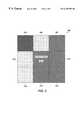
- FIG. 1An example of a manually contoured CT image slice or section is shown in FIG. 1 generally at 100 .
- the manually contoured organsare liver 102 , spleen 104 , left kidney 106 , right kidney 108 , and spinal cord 110 .
- FIG. 2shows an example of a 3-D reconstruction that uses as an element the 2-D slice or section shown in FIG. 1 at 100 .
- the reconstruction in FIG. 2is composed of contours from a contiguous set of slices or sections.
- the 3-D reconstruction of the liveris at 202
- the spleenis at 204
- the right kidneyis at 206
- the left kidneyis at 208
- the spinal cordis at 210 .
- segmentationis the identification of image objects as distinct regions or segments of an image. This method also may be used to generate 3-D reconstructions of a patient's anatomy.
- contouring and segmentationare taken to have the same meaning for description purposes herein.
- Pixel/voxel valueswhich exist as intensities or gray levels, and their distributions across an image form a useful set of properties for segmentation.
- the edges of objects that are shownusually are associated with large value differences with nearby pixel values.
- the interiors of discrete objectstend to have relatively constant values.
- discrete objectsexhibit distinct gray level textures in such a manner that adjoining objects or regions with different textures appear to have visible boundaries between them.
- Each of these qualities of edgeness and textureare associated with one or more computational methods that may be used to generate a numerical value for that property. As quantified, these properties can be used to make decisions about the segment identity of individual pixels.
- the operatorselects image pixels from distinct tissue in each of two or more multi-modal MRI image sets.
- the computer-based programthen computes class conditional probability density parameters based on the assumption of a multivariate, Gaussian distribution data model. From seed pixels, the various tissues elements are grown outward by setting adjacent voxel labels according to a maximum likelihood decision rule. The labeling process is carried out over the 3-D data of the multi-modal MRI image set, followed by smoothing of the segmented region boundaries to reduce noise.
- a semi-automated segmentation methodis reported in DeCarli, C., Maisog, J., Murphy, D. G. M., et al., Method for quantification of brain, ventricular, and subarachnoid CSF volumes from MRI images, Journal of Computer Assisted Tomography, 16(2):274-284 (1992).
- This approachis directed to segmentation of major brain regions, e.g., the cerebral cortical hemispheres, cerebellum, etc., based on an analysis of gray level histograms derived from manual samples of pixel values corresponding to respective brain tissue types.
- MRImagnetic resonance imaging
- MRI scannerscan be set to produce images emphasizing proton density or different relaxation phenomena.
- multi-modal MRIin principle, can provide more information for each voxel.
- the few fully automated, computed segmentation techniques that have been reportedhave been directed to the segmentation of the brain gray matter, white matter, and cerebrospinal fluid (“CSF”) spaces using multi-modality MRI. These approaches use statistical pattern recognition methods to distinguish the various materials.
- the main fully automated computed segmentation techniques using multi-modal MRIare disclosed and described in Bezdek, J. C., Hall, L. O., Clarke, LP, Review of MR image segmentation techniques using pattern recognition, Medical Physics, 20:1033-1048 (1993); Fletcher, L. M., Barsotti, J. B., and Hornak, J.
- a different strategy for fully automated, computed segmentationis to map a labeled atlas onto patient data by nonlinear transformations, referred to as warping.
- This techniquewill produce local correspondences between the atlas and individual patient anatomies despite inter-subject anatomic differences.
- An example of this strategyis reported in Miller MI, Christensen, G. E., Amit, Y., Grenander, U., Mathematical textbook of deformable neuroanatomies, Proceedings of the National Academy of Sciences USA, 90:11944-11948 (1993).
- the Miller et al. articledescribes a procedure in which an elastic model of the brain anatomy is driven by data-overlap probabilities to warp brain atlas images onto MRI slice or section images. In this case, segmentation occurs by associating the image voxels with atlas tissue-type labels.
- ChakrabortyA further example of a fully automated, computed segmentation method is described in Chakraborty, A., Staib, L. H., Duncan, J. S., Deformable boundary finding in medical images by integrating gradient and region information, IEEE Transaction on Medical Imaging, 15:859-870 (1996).
- the method set forth in the Chakraborty et al. articleis directed to acquiring images of the left ventricle at intervals in the cardiac cycle which are then used to construct 3-D models of the left ventricle to study cardiac function.
- the present inventionis an autocontouring/autosegmentation system and method for automatically computing contours representative of the boundaries of anatomical objects in two-dimensional (“2-D”) and three-dimensional (“3-D”) tomographic images generated using computed tomography (“CT”) magnetic resonance imaging (“MRI”), positron emission tomography (“PET”), single photon emission computed tomography (“SPECT”), or other appropriate method.
- CTcomputed tomography
- MRImagnetic resonance imaging
- PETpositron emission tomography
- SPECTsingle photon emission computed tomography
- the system and methodare useful for determining the boundary contours of an object in multiple sections of a 3-D tomographic image in a novel way.
- the contours generated according to the system and method of the present inventionoptimally match (1) local image gray level gradients, (2) the edges of the segmented object, and (3) the prior contour shape of the object at issue. These contours substantially conform to anatomic shapes with greater accuracy than hand-drawn contours.
- the system and method of the present inventionprovide an objective method for contour construction based on quantitative measurements of properties of the images themselves. More specifically, the system and method of the present invention combines region, edge, and shape information to provide more accurate contours than methods using either region-growing or active contour approaches alone, such as reported in Chakraborty, A., Staib, L. H., Duncan, J. S., Deformable boundary finding in medical images by integrating gradient and region information, IEEE Transactions on Medical Imaging, 15:859-870 (1996). Further, the system and method of the present invention produce accurate contours in many anatomic sites, in images of variable quality, and require user interaction only to generate the first contour of an object.
- the contours that are generatedare closed parametric curves such that the (x,y) coordinates of points on the curve are themselves continuous functions of arc-length t and the set of real-valued parameters, p, as provided for in Expression (1):
- (x,y)the Cartesian coordinates of a point on a curve.
- tthe arc-length distance of a point (x,y) from an origin point.
- pa set or vector of real-value parameters.
- x(p,t)the x coordinate based on parameters p and arc-length distance t.
- y(p,t)the y coordinate based on parameters p and arc-length t.
- the functions that define (x,y)will generate curves of arbitrary shape and size depending on the values of the parameters p.
- the parameters pserve as independent variables of an objective function which takes on greater or lesser values depending on the correlation of the computed, parametric contour and the actual object boundary in the image.
- the objective function that has been referred tois determined by the sum of functions of the a posteriori conditional probabilities of the computed, parametric contour given: (1) the quality of the match of the computed boundary with the perimeter of the interior region of the actual object, (2) the coincidence of the boundary with the local gray level gradient maxima, and (3) the similarity of the shapes of the estimated boundary with previously-determined, section boundaries of the actual object.
- the objective functionis based on a Bayesian formulation to insure that the maximum a posteriori (MAP) result will be associated with the minimum average error in the contour determinations
- MAPmaximum a posteriori
- the formulation of the objective function as a function of a posteriori probabilitiesfollows what is set forth in Chakraborty, A., Staib, L. H., Duncan, J. S., Deformable boundary finding in medical images by integrating gradient and region information, IEEE Transactions on Medical Imaging, 15:859-870 (1996) which thereby becomes part of the segmentation and method of the present invention.
- This maximized objective functionis in the form M(p,I g ,I r ), where, p is the set of real-value parameters, I g is the gray-level gradient image, and I r is the region-classified image.
- the methodinitially requires a sample of the interior of the object to be contoured, called the region-of-interest (“ROI”), which is obtained either by automated comparison with a neighboring section previously contoured by this method, or by manual input using interactive computer graphics.
- ROIregion-of-interest
- the system and method of the present inventionthen expands the ROI in a stepwise fashion by: (1) adding one layer of pixels where possible to the region's perimeter, (2) renumerating the perimeter, and (3) determining the set of parameters which maximally satisfy the three criteria above. Expansion continues in this manner to an appropriate stopping point. Once this is done, the object contour is defined by the set of parameters corresponding to the maximum value of the objective function over all the expansion steps.
- the expansion or growing of the ROI according to the present inventionis accomplished by testing image pixels outside the region, but adjacent to the region's perimeter.
- the decision whether a pixel being tested belongs inside or outside of the regionis made by a supervised classifier decision method.
- This methodcomputes the values of discriminant functions (one each for each possible outcome) and chooses the outcome corresponding the highest valued discriminant function.
- the discriminant functionis characterized by the assumption that the pixel gray level properties form multivariate Gaussian probability distributions.
- This supervised classifier decision methodis developed de novo for each ROI for each section of each object.
- the values of the discriminant functionsare set by the values of pixel gray-level properties and an assumed statistical model for those properties.
- FIG. 1shows a 2-D CT slice or section image through the abdomen, with certain organ contours labeled.
- FIG. 2shows a graphical representation of a 3-D reconstruction of the abdominal anatomy (which incorporates the 2-D CT slice or section image in FIG. 1 ), with certain organ contours labeled.
- FIG. 3is a graphical representation of a target pixel and the 3 ⁇ 3 set of pixels that influence the properties of the target pixel.
- FIGS. 4A, 4 B, 4 C, 4 D, 4 E, and 4 Fshow a series of synthetic pictures in which the boundary (black) to be contoured is defined a priori by a fixed set of parameters p, and the computed contour (white) corresponds to the best, or maximum M(p,I g ,I r ) objection function, for varying numbers of Fourier harmonics, N.
- FIGS. 5A, 5 B, 5 C, and 5 Dshow a series of synthetic pictures in which the boundary (black) to be contoured is defined a priori by a fixed set of parameters p, (as used in FIG. 4 ), and to which increasing levels of Gaussian noise has been added.
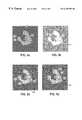
- FIGS. 6A, 6 B, 6 C, 6 D, 6 E, and 6 Fshow a series of pictures of a section of the left kidney in which at FIG. 6A an interior sample is inscribed (black polygon) by interactive graphics, and a contour is computed to fit the kidney boundary (dashed), and FIGS. 6B-6F show successive sections with significant variations in the shape details and interior texture of the left kidney.
- the present inventionis a system and method for automatically generating accurate 2-D and 3-D contours using maximum a posteriori (MAP) autocontouring/autosegmentation.
- the boundary contours of a 3-D tomographic reconstruction of an objectmay be determined from a contiguous set of 2-D slices or sections. These boundary contours optimally match the local image gray level gradients, the edges of the segmented object with accuracy, and the shape of the prior contour of the object.
- the system and method of the present inventioneffectively use region, edge, and prior shape information to provide accurate boundary contours in a novel way.
- the present inventiongenerates the maximized objective function based on MAP regional growing, MAP boundary detection, and knowledge of the parametric representation of boundary shape. Each of these areas will now be discussed.
- minimum Bayes riskis reported in Van Trees, H. L., Detection, Estimation, and Modulation Theory, Part I, Wiley, New York, 1968. According to this reference, minimum Bayes risk is a decision criterion which guarantees, on average, that the results of classification decisions will have the lowest expected loss. That is, if each possible decision outcome is assigned a loss (or cost), Minimum Bays risk decisions will have minimum average loss.
- minimum Bayes erroris the criterion for reclassifying an ROI-adjacent, outside pixel as an inside pixel.
- Bayes rulesprovide the method to compare the features' probability descriptions across classes to make a minimum error decision.
- Xwill represent a vector whose component values are the gray-level-derived properties, or features, for a single pixel whose class membership is to be tested. At least some of the features for this single pixel will normally have different values depending on its class, so the probability densities becomes the class conditional probability density p(X
- the relative probability that class i is observed relative to other classesis the a priori probability P(i).
- the probability that class i is the correct class for observation Xis the a posteriori probability P(i
- X)the a posteriori probability that class i in the correct class given vector X.
- i)the conditional probability of observing vector X given class i.
- P(i)the a priori probability that class i is observed.
- k)the conditional probability of observing vector X given class k.
- P(k)the a priori probability that class k is observed.
- k)P(k)the sum of the products of the probability of observing vector X given class k and the a priori probability that class k is observed.
- X)the a posteriori probability that class i is the correct class given vector X.
- X)the a posteriori probability that class i is the correct class given vector X.
- X)the a posteriori probability that class j is the correct class given vector X.
- the decision rule at Expression (4)represents the maximum a posteriori probability rule. If prior probabilities are unknown, then the conditional probabilities, p(X
- i)the conditional probability of observing vector X given class i.
- j)the conditional probability of observing vector X given class j.
- Ra threshold value greater than zero (0), which can accommodate changes in the estimates of prior probabilities, or give a minimum-error decision on known data (according to Van Trees, H. L., Detection, Estimation, and Modulation Theory, Part I, Wiley, New York, 1968).
- the MAP probability rule for all classesas set forth in Expression (3) is the appropriate rule to use.
- Expression (3)A review of Expression (2) indicates that it can be written in a more convenient form for use in the method and system of the present invention. From Expression (3), it is understood that p(i
- i)The conditional probability of observing vector X given class i.
- P(i)The a priori probability that class i is observed.
- j)The conditional probability of observing vector X given class j.
- P(j)The a priori probability that class j is observed.
- g i (X)A function of the a posteriori probability P(i
- g j (X)A function of the a posteriori probability P(j
- g j (X)A function of the a posteriori probability P(j
- dThe number of feature-components in vector X.
- M iThe vector of feature means for class i.
- ⁇ iThe matrix of covariances for the features in class i.
- ⁇ i ⁇ 1The inverse covariance matrix for the features in class i.
- TTranspose of the given vector.
- M iThe vector of feature means for class i.
- ⁇ iThe matrix of covariances for the features in class i
- ⁇ i ⁇ 1The inverse covariance matrix for the features in class i.
- dThe number of feature-components in vector X.
- P(i)The a priori probability that class i is observed.
- the MAP test for two classes i and jis the decision whether to classify a given pixel to the class of pixels belonging to the sample polygon, such as class i, or to the class of pixels outside the sample polygon, such as class j, based on the previously provided in Expression (7), which for convenience is provided here:
- g i (X)A function of the a posteriori probability P(i
- g j (X)A function of the a posteriori probability P(j
- the numeric valuescan include the mean, standard deviation, skewness, kurtosis, energy, entropy, and the range, but also other texture measures. However, it is understood that there can be more gray-level-derived properties for which numeric values may be generated.
- the neighborhood that has been referred topreferably is a 3 ⁇ 3-pixel set, or the 8 pixels adjacent to the given pixel, minus any pixels not inside the ROI.
- the mean feature vectors M i and the covariance matrices ⁇ ican be computed and inserted into the Expression (10) for use in the decision rule at Expression (7).
- FIG. 3A representative 3 ⁇ 3 pixel set is shown graphically in FIG. 3, generally at 300 .
- the pixel of interestis center pixel 302 .
- the pixels that influence the numeric values of center pixel 302are the 8 pixels adjacent to it. These are pixels 304 , 306 , 308 , 310 , 312 , 314 , 316 , and 318 . These 8 pixels and the center pixel form the 3 ⁇ 3 pixel set except for pixels at, or adjacent to, the boundary of the polygon which fall outside the ROI.
- Autocontouring/autosegmentationimposes three constraints on the probabilistic growth of the ROI to match to an image object boundary.
- the firstis that the initial ROI polygon be entirely within the object being contoured. If the initial ROI polygon spans the boundaries between different anatomic structures, the present invention will not expand the boundary properly.
- the secondis that the ROI grows only be accreting former outside pixels. As such, no inside pixels are allowed to revert to outside at any point in the growth process.
- the third constraintis that any outside pixels that become completely surrounded by inside pixels are converted to be inside pixels.
- the resulting ROI perimeterwill define a simply connected object.
- the shapes of objects appearing in two or more serial-section imagessatisfy three properties: (1) the object boundaries coincide with local maxima in the magnitude of the gray level gradient, (2) the boundary-enclosed regions have nearly homogenous textures, and (3) profiles of objects in a given section will be similar to those in the adjacent sections.
- Homogeneous texturesare gray-level properties that have constant means and variances across the whole region. The degree to which any trial contour coincides with local gradients and segmented region-edges, and agrees with shapes of prior contours, depends on the details of its shape.
- computed contoursare represented by continuous functions of shape parameters.
- the (x,y) coordinates of the points on the contourare themselves functions of the arc-length distance along the curve, t, along with the set (or vector) of parameters p, (x(p,t),y(p,t)). If the total length of the contour is T, then 0 ⁇ t ⁇ T.
- the values of the parametersare given by equations for the Fourier elliptic representation which are described in detail below in the section entitled “Parametric Representation of Boundary Shape.”
- the contour parametersalso serve as independent variables for the objective function that (1) measures the region-edge and gradient-edge overlap, and (2) the similarity of the current contour with prior contours.
- this objective functionassumes a maximum value for the set of parameters p that correspond to the contour which most satisfies the three criteria stated at the beginning of this section.
- the objective function used in the system and method of the present inventionis a function of the conditional probability reported in Chakraborty, A., Staib, L. H., Duncan, J. S., Deformable boundary finding in medical images by integrating gradient and region information, IEEE Transactions on Medical Imaging, 15:859-870 (1996).
- This objective functionis in the form of Expression (11):
- Pa set or vector of real-value parameters.
- I rthe region-classified image.
- I gthe gray-level gradient image.
- the probability depicted by Expression (11)is the probability of obtaining the contour with parameter vector p given the region-classified image I r , and the image of the scalar magnitude of the gray level gradient I g .
- the components of parameter vector pare treated as random variables, and parameter vector p is assumed to have a multivariate, Gaussian distribution probability density.
- P(p, I r , I g )The joint probability of contour vector p, I r , and I g .
- I g ,p)The conditional probability of I r given I g and p.
- P(p, I g )The joint probability of contour vector p and I g .
- P(I g , I r )The joint probability of contour vector I g and I r .
- I g )The conditional probability of p given I g .
- P(p)The a priori probability of the contour p.
- I rThe region-classified image produced by the MAP region growing method described above.
- I gThe gray-level gradient image.
- I g ,p)The conditional probability of I r given I g and p.
- the first termis the natural logarithm of the probability of a region image I r given gradient image I g and contour parameters p.
- the second termis the natural logarithm of the probability of obtaining a contour parameters p given the gradient image I g .
- the third termis the natural logarithm of the probability of a given contour parameters p.
- M prior (p)the function of the similarity of contour parameters p and the parameters of the corresponding contour of a neighboring section.
- M gradient (I g , p)the function of the similarity of the gradient maxima and the contour specified by parameters p.
- M region (I r , p)the function of the similarity of the classified region edge and the contour specified by parameters p.
- the first (prior) termbiases the boundary toward a particular distribution of shapes generated from prior experience.
- the second (gradient) termcontributes the most when the parametric boundary p, defined as the discrete boundary x(p,t),y(p,t), most closely matches the coherent edge features in I g .
- the third (region) termis maximized when the parametric boundary p most closely matches the edges of the segmented region.
- the value of the M region (p,I r ) term in Expression (14)depends on the match of the parametric boundary with the edge of the region. Chakraborty, A., Staib, L. H., Duncan, J. S., Deformable boundary finding in medical images by integrating gradient and region information, IEEE Transactions on Medical Imaging, 15:859-870 (1996) describes a method to maximize the exactness of the fit. This method rewards the boundary that contains as much of the inside region as possible, and penalizes the boundary that includes any of the outside pixels. The desired result is obtained by integrating over the area of a region template A p according to Expression (15):
- I rthe region-classified image.
- pa set of real-value parameters.
- a pthe area of the region template.
- I rthe region-classified image.
- a pthe area of the region template.
- N r , M rthe auxiliary functions defined in Expressions (17) and (18) below.
- tthe arc-length distance of a point (x,y) from an origin point.
- M r and N rmay be written as Expressions (17) and (18):
- M r ⁇ ( x , y )⁇ 0 x ⁇ I r ⁇ ( z , y ) ⁇ ⁇ ⁇ z ( 17 )
- N r ⁇ ( x , y )- ⁇ 0 y ⁇ I r ⁇ ( x , z ) ⁇ ⁇ ⁇ z ( 18 )
- I rThe region-classified image.
- (x,y)The x and y coordinates of a point.
- the image I rcontains a template of the segmented region with pixel values of one (1) for pixels inside the region, and ⁇ 1 for pixels outside the region.
- M region (I r , p)the function of the similarity of the region-classified edge and the contour specified by parameters p.
- Kthe length of the contour in pixels.
- N r , M rthe auxiliary functions defined in Expressions (17) and (18) above.
- x(p,t)the x coordinate for specific values of parameters p and arc-length distance t.
- y(p,t)the y coordinate for specific values of parameters p and arc-length distance t.
- ⁇ xthe finite difference computed from actual x values at pixel locations.
- ⁇ ythe finite difference computed from actual y values at pixel locations.
- ⁇ tthe finite difference computed from actual t values at pixel locations.
- N r , M rthe auxiliary functions defined above.
- I rthe region-classified image.
- zthe index of sums over x or y coordinates.
- M gradient (p,I g )depends on the coincidences of the parameterized boundary with edges in the image appearing as coherent features in the scalar gradient of the original image gray levels.
- the gradient termis a contour integral whose domain is the parametric contour C p realized by the discrete boundary [x(p,t),y(p,t)].
- M gradient ⁇ ( p , I g )k 1 ⁇ 2 ⁇ ⁇ C p ⁇ I g ⁇ [ x ⁇ ( p , t ) , y ⁇ ( p , t ) ] ⁇ ⁇ t ( 22 )
- I gThe gray-level gradient image.
- pa set of real-value parameters.
- x(p,t)the x coordinate for values of parameters p and arc-length distance t.
- y(p,t)the y coordinate for values of parameters p and arc-length distance t.
- ⁇ 2the noise variance
- I gThe gray-level gradient image.
- Kthe length of the contour in pixels.
- pa set of real-value parameters.
- x(p,t)the x coordinate for values of parameters p and arc-length distance t.
- y(p,t)the y coordinate for values of parameters p and arc-length distance t.
- p ithe i-th component of the contour parametric vector p.
- ⁇ ithe standard deviation for the component p i of the contour vector p.
- m ithe mean value for the component p i of the contour vector p.
- p ithe i-th component of the contour vector p.
- ⁇ ithe standard deviation for the component p i of the contour vector p.
- m ithe mean value for the component p i of the contour vector p.
- the functional form of the boundary parameterizationis the Fourier elliptical representation. This is reported in Giardina, C. R. and Kuhl, F. P., Accuracy of curve approximation by harmonically related vectors with elliptical loci, Computer Graphics and Image Processing, 6:277-285 (1977); and Kuhl, F. P. and Giardina, C. R., Elliptic Fourier features of a closed contour, Computer Graphics and Image Processing, 18:236-258 (1982). According to these references, an object boundary contour is considered to be a closed, continuous curve V(p,t), where t is the arc-length and p is the parameter vector. The curve has a total length T, such that 0 ⁇ t ⁇ T.
- x(p,t)the x coordinate for values of parameter p and arc-length distance t.
- y(p,t)the y coordinate for values of parameter p and arc-length distance t.
- pa set of real-value parameters.
- tthe arc-length distance of a point (x(p,t),y(p,t)) from an origin point.
- the contour vector pis the set of Fourier coefficients ⁇ a 0 ,c 0 ,a 1 ,b 1 ,c 1 ,d 1 , . . . ,a n ,b n ,c n ,d n ⁇ , and N is the total number of Fourier harmonics.
- Maximization of the objective function, M(p,I g ,I r )is carried out over the vector ⁇ p 1 ,p 2 , . . . p 4N+2 ⁇ , and the resulting contour is computed directly using Expressions (28) and (29).
- the parameterizationis global in that each parameter p i makes a contribution to (x(p,t),y(p,t)) at every value of t.
- ⁇ xthe finite difference computed from actual x(k) values at pixel locations.
- ⁇ ythe finite difference computed from actual y(k) values at pixel locations.
- ⁇ tthe finite difference computed from actual t values at pixel locations.
- Kthe length of the contour in pixels.
- Tthe total contour length
- tthe arc-length distance of a point x(k),y(k) from an origin point.
- ⁇ xthe finite difference computed from actual x values at pixel locations.
- ⁇ ythe finite difference computed from actual y values at pixel locations.
- ⁇ tthe finite difference computed from actual t values at pixel locations.
- Kthe length of the contour in pixels.
- Tthe total contour length
- tthe arc-length distance of a point x(k),y(k) from an origin point.
- the relationship between the number of harmonics producing the best boundary-contour match and the contour lengthmay be obtained, for example, by examining the contours produced for a series of abdominal organs with boundary lengths spanning an order of magnitude (see FIGS. 4 A- 4 F). For each object, contours may be computed with increasing numbers of harmonics until the good matches are succeeded by noisy contours (see FIGS. 5 A- 5 D).
- Kthe length of the contour in pixels.
- N*the number of Fourier harmonics.
- Expression (36)permits the system and method of the present invention to adapt to objects of varying size.
- the set of parameters p in Expression (1)serve as independent variables of the objective function M(p,I r , I g ), described above.
- the objective functionassumes greater or lesser values (and significance) depending on the correlation of the computed, parametric contour and the actual object boundary of the image.
- the objective functionis based on the sum of functions of the a posteriori probabilities of the computed, parametric contour given:
- the estimation and growing of the computed contouris based on the Baysian formulation of the objective function which insures that a maximum a posteriori (MAP) result will be associated with the minimum average error in computed, contour determinations.
- MAPa maximum a posteriori
- the system and method of the present inventionare used to generate computed contours that may be used for 2-D contouring and 3-D reconstructions, for example, of an anatomical areas of interest.
- the system and method of the present inventionuse data from the previously-contoured sections to generate contours for other sections, automatically, and without any user input. Generation of an initial contour does require interactive input, and that part of the system and method of the present invention will be described following the description of the automated contouring method.
- the largest connected set of k pixels similar to the (k ⁇ 1) contour interior-pixelsis the starting point for iterative region growing.
- the mean vectors m i (k) and inverse covariance matrices [ ⁇ i ⁇ 1 ] (k)are computed. Only one set of mean vectors and covariances are computed for each class i for the current section k.
- the present inventionexpands I r (k,l-1) by one pixel layer to form I r (k,l) , and re-enumerates all the region perimeter pixels.
- the present inventionthen forms from the I r (k,l) perimeter pixels, a set of contour parameters, p (k,*) , and probability densities P(p (k,*) ), where * indicates that these form the initial value set before maximization of the objective function, and where the number of parameters (components of p) is varied with respect to the length of the contour to obtain the minimum-error match of contour to boundary.
- the present inventionthen maximizes the objective function in terms of the p parameters.
- the l-th cycle functionis M (k,l) (p (k,l) , I g (k) ,I r (k,l) ) with the superscripts indicating that parameters p (k,l) and region-increment I r (k,l) are specific to present iteration step.
- the present inventiontests the growth of the region to determine if it is at the maximum based on the decision rules for growth. This test is according to the following procedures:
- M ( k ) ⁇ ( p ( k ) , I g ( k ) , I r ( k ) )max l ⁇ [ M ( k , l ) ⁇ ( p ( k , l ) , I g ( k ) , I r ( k , l ) ) ] ( 37 )
- kis incremented by 1 for a new section and the process is repeated for this new section to be contoured.
- the ROIor polygonal sample
- the texture classifierhas feature mean vectors and covariance matrices according to the following:
- Each pixel outside of, and adjacent to, the ROIis tested, and if it is more like the inside pixels, its label is changed from OUTSIDE to INSIDE.
- the present inventionthen re-enumerates all the perimeter pixels, and repeats the testing of all outside, ROI-adjacent pixels. This process is repeated until no further adjacent pixels pass the test.
- the last ROIis taken to be I r (0) .
- FIGS. 4A-4Fshow a series of regions that have been grown using different values of Fourier harmonics, N. More specifically, these figures consist of a series of synthetic pictures in which the boundary (black) to be contoured is defined a priori by a fixed set of parameters p and the computed contour (white) corresponds to the best or maximum M(p,I g ,I r ) objective function for the different numbers of Fourier harmonics, N.
- M(p,I g ,I r ) objective functionfor the different numbers of Fourier harmonics, N.
- Table 1A comparison of the number of Fourier harmonics, N, and the RMS error values for FIGS. 4A-4F is shown in Table 1:
- FIG. 4Ashows boundary 402 and computed contour 404 ;
- FIG. 4Bshows boundary 406 and computed contour 408 ;
- FIG. 4Cshows boundary 410 and computed contour 412 ;
- FIG. 4Dshows boundary 414 and computed contour 416 ;
- FIG. 4Eshows boundary 418 and computed contour 420 ;
- FIG. 4Fshows boundary 422 and computed contour 424 .
- FIGS. 4A to 4 FIn the set of matches defined by FIGS. 4A to 4 F, it is readily seen that the match between boundary 402 and computed contour 404 in FIG. 414 and boundary 406 and computed contour 408 in FIG. 4B is not particularly good because much of the detail of the boundaries are not found in the contours. It is to be noted that FIGS. 4A and 4B correspond to Fourier harmonic values of 2 and 4, respectively. It also is to be noted that the RMS (root mean square) error values are high for these harmonics. These high values are 6.8 for FIG. 4A and 5.1 for FIG. 4 B.
- FIG. 4Cwhich used 8 Fourier harmonics, has a significantly improved match between boundary 410 and computed contour 412 .
- Table 1also shows that the RMS error value has significantly decreased to 1.6 compared to the RMS error values of 6.8 and 5.1 for Fourier harmonics values of 2 and 4, respectively. Even with the improved matching in FIG. 4C, some of the detail of the boundary is missing in the computed contour
- FIGS. 4D, 4 E, and 4 Fcorrespond to Fourier harmonics of 16, 32, and 64, respectively. These Figures show significantly better matching between boundary 414 and computed contour 416 in FIG. 4D, boundary 418 and computed contour 420 in FIG. 4E, and boundary 422 and computed contour 424 in FIG. 4 F. In these successive figures, the computed contours that were grown with increasing numbers of Fourier harmonics become more defined compared to the boundaries. However, the incremental improvement is not primarily significant in evaluating the matches at FIGS. 4D, 4 E and 4 F. This also is indicated by the RMS values for FIGS. 4D to 4 F being about the same.
- FIGS. 5A, 5 B, 5 C, and 5 Dshow a series of regions that have been evaluated for noise. More specifically, FIGS. 5A to 5 D show a series of synthetic pictures in which the boundary (black) to be contoured is defined a priori by a fixed set of parameters p, which are identical to the set of parameters used in FIGS. 4A to 4 F, and Gaussian distribution noise was added to the image. These images demonstrate the effect of noise on computed contour accuracy. Ten (10) Fourier harmonics are used for each of the figures. A comparison of the SNR (signal-to-noise ratio) and the RMS error for FIGS. 5A-5D is shown in Table 2:
- boundary 502defines ROI 504 .
- Initial polygon 506is found in ROI 504 to be grown to boundary 502 .
- the success in growing polygon 506is influenced by the clarity of the boundary between the ROI 504 and the area 508 outside ROI 504 .
- the SNRis infinite. As is seen in reviewing FIG. 5A, there is a contrast between ROI 504 and area 508 outside boundary 502 , but this high SNR also causes ROI 504 to have a significant gray-level value that is not desirable. This is true even though the RMS error is at a relatively low level.
- boundary 510defines ROI 512 .
- Initial polygon 514is formed in ROI 512 .
- the SNRis 2.0 and the RMS error has remained the same as it was when the SNR was infinite.
- ROI 512is in clear contrast to area 516 outside of ROI 512 . This is a desirable situation to grow initial polygon 514 because this stark contrast will facilitate the growth to boundary 510 but not beyond it given the decision rules used by the present invention.
- boundary 520defines ROI 502 and initial polygon 524 is formed in ROI 522 .
- boundary 530defines ROI 532 and initial polygon 534 is formed in ROI 532 .
- FIG. 5Cthere is not a great amount of contrast between the gray-level values in ROI 522 and the area 526 outside of ROI 522 .
- FIG. 5Dthere is not a great amount of contrast between the gray-level values in ROI 532 and the area 536 outside of ROI 532 .
- FIGS. 5C and 5Dshow situations in which the SNR is 1.0 and 0.5 respectively. It also is seen that the RMS error values have increased slightly when the SNR has decreased to 1.0, but increased significantly when the SNR has decreased to 0.5. These RMS error values are 1.6 to 3.6, respectively. In viewing FIGS. 5C and 5D, it is evident that as the SNR is decreased from 2.0 to 1.0 and 0.5, the difference between the gray-level values of pixels inside the ROI and outside the ROI is much less distinguishable. Therefore, after considering FIG. 5B, FIGS. 5C or 5 D would not be desired environments for growing polygon to match the ROI boundary.
- FIGS. 6A, 6 B, 6 C, 6 D, 6 E, and 6 Fshow a series of pictures of a section of left kidney 602 .
- ten (10) Fourier harmonicswere used.
- FIG. 6Ashows kidney 602 with interior inscribed (black polygon) 604 .
- Polygon 604is inscribed using interactive graphics. From inscribed polygon 604 , the present invention was used to compute the contour (dashed) 606 to fit the boundary kidney 602 .
- FIGS. 6B to 6 Fshow succeeding sections of left kidney 602 with significant variations in shape detail and interior textures.
- the present inventionwas used to compute a contour that would fit the kidney section boundary.
- contour 606was computed
- FIG. 6C contour 608was computed
- FIG. 6D contour 610was computed
- FIG. 6E contour 612was computed
- FIG. 6F contour 614was computed.
- the various kidney shapes and interior texturesdo not have any significant effect on the ability of the system and method of the present invention to compute the contours in FIGS. 6A-6F.
Landscapes
- Engineering & Computer Science (AREA)
- Physics & Mathematics (AREA)
- Computer Vision & Pattern Recognition (AREA)
- Theoretical Computer Science (AREA)
- General Physics & Mathematics (AREA)
- Nuclear Medicine, Radiotherapy & Molecular Imaging (AREA)
- Quality & Reliability (AREA)
- Radiology & Medical Imaging (AREA)
- Health & Medical Sciences (AREA)
- Medical Informatics (AREA)
- General Health & Medical Sciences (AREA)
- Probability & Statistics with Applications (AREA)
- Software Systems (AREA)
- Magnetic Resonance Imaging Apparatus (AREA)
- Radiation-Therapy Devices (AREA)
- Image Processing (AREA)
Abstract
Description


| TABLE 1 | ||
| Figure | N | RMS error |
| 4A | 2 | 6.8 |
| 4B | 4 | 5.1 |
| 4C | 8 | 1.6 |
| 4D | 16 | 0.69 |
| 4E | 32 | 0.61 |
| 4F | 64 | 0.69 |
| TABLE 2 | ||
| Figure | SNR | RMS error |
| 5A | ∞ | 1.2 |
| 5B | 2.0 | 1.2 |
| 5C | 1.0 | 1.6 |
| 5D | 0.5 | 3.6 |
Claims (22)
Priority Applications (5)
| Application Number | Priority Date | Filing Date | Title |
|---|---|---|---|
| US09/087,254US6249594B1 (en) | 1997-03-07 | 1998-05-29 | Autosegmentation/autocontouring system and method |
| AT99925914TATE251785T1 (en) | 1998-05-29 | 1999-05-27 | SELF SEGMENTATION/CONTOUR OBTAINING METHOD |
| EP99925914AEP1080449B1 (en) | 1998-05-29 | 1999-05-27 | Autosegmentation / autocontouring system |
| DE69911958TDE69911958T2 (en) | 1998-05-29 | 1999-05-27 | SELF SEGMENTATION / CONTOUR PROCESSING PROCESS |
| PCT/US1999/011710WO2000008600A1 (en) | 1997-03-07 | 1999-05-27 | Autosegmentation / autocontouring system and method |
Applications Claiming Priority (2)
| Application Number | Priority Date | Filing Date | Title |
|---|---|---|---|
| US08/813,701US5859891A (en) | 1997-03-07 | 1997-03-07 | Autosegmentation/autocontouring system and method for use with three-dimensional radiation therapy treatment planning |
| US09/087,254US6249594B1 (en) | 1997-03-07 | 1998-05-29 | Autosegmentation/autocontouring system and method |
Related Parent Applications (1)
| Application Number | Title | Priority Date | Filing Date |
|---|---|---|---|
| US08/813,701Continuation-In-PartUS5859891A (en) | 1997-03-07 | 1997-03-07 | Autosegmentation/autocontouring system and method for use with three-dimensional radiation therapy treatment planning |
Publications (1)
| Publication Number | Publication Date |
|---|---|
| US6249594B1true US6249594B1 (en) | 2001-06-19 |
Family
ID=25213122
Family Applications (2)
| Application Number | Title | Priority Date | Filing Date |
|---|---|---|---|
| US08/813,701Expired - LifetimeUS5859891A (en) | 1997-03-07 | 1997-03-07 | Autosegmentation/autocontouring system and method for use with three-dimensional radiation therapy treatment planning |
| US09/087,254Expired - LifetimeUS6249594B1 (en) | 1997-03-07 | 1998-05-29 | Autosegmentation/autocontouring system and method |
Family Applications Before (1)
| Application Number | Title | Priority Date | Filing Date |
|---|---|---|---|
| US08/813,701Expired - LifetimeUS5859891A (en) | 1997-03-07 | 1997-03-07 | Autosegmentation/autocontouring system and method for use with three-dimensional radiation therapy treatment planning |
Country Status (7)
| Country | Link |
|---|---|
| US (2) | US5859891A (en) |
| EP (1) | EP0965104B1 (en) |
| AT (1) | ATE205320T1 (en) |
| AU (1) | AU6444998A (en) |
| DE (1) | DE69801562T2 (en) |
| ES (1) | ES2159939T3 (en) |
| WO (2) | WO1998039736A1 (en) |
Cited By (106)
| Publication number | Priority date | Publication date | Assignee | Title |
|---|---|---|---|---|
| US20010041838A1 (en)* | 1995-07-26 | 2001-11-15 | Holupka Edward J. | Virtual reality 3D visualization for surgical procedures |
| US6385479B1 (en)* | 1999-03-31 | 2002-05-07 | Science & Technology Corporation @ Unm | Method for determining activity in the central nervous system |
| US6430427B1 (en)* | 1999-02-25 | 2002-08-06 | Electronics And Telecommunications Research Institute | Method for obtaining trabecular index using trabecular pattern and method for estimating bone mineral density using trabecular indices |
| US20020118229A1 (en)* | 2001-02-20 | 2002-08-29 | Yoshiyuki Batori | Information processing apparatus and method |
| US6466813B1 (en)* | 2000-07-22 | 2002-10-15 | Koninklijke Philips Electronics N.V. | Method and apparatus for MR-based volumetric frameless 3-D interactive localization, virtual simulation, and dosimetric radiation therapy planning |
| US20020150298A1 (en)* | 2001-01-12 | 2002-10-17 | Ram Rajagopal | System and method for signal matching and characterization |
| US20030053671A1 (en)* | 2001-05-10 | 2003-03-20 | Piet Dewaele | Retrospective correction of inhomogeneities in radiographs |
| US20030135102A1 (en)* | 2000-05-18 | 2003-07-17 | Burdette Everette C. | Method and system for registration and guidance of intravascular treatment |
| US20030212321A1 (en)* | 2002-03-07 | 2003-11-13 | Baxter Walton W. | Algorithm for accurate three-dimensional reconstruction of non-linear implanted medical devices in VIVO |
| US20030229282A1 (en)* | 1997-11-24 | 2003-12-11 | Burdette Everette C. | Real time brachytherapy spatial registration and visualization system |
| US6674880B1 (en)* | 1999-11-24 | 2004-01-06 | Confirma, Inc. | Convolution filtering of similarity data for visual display of enhanced image |
| US6684097B1 (en)* | 1999-04-22 | 2004-01-27 | University Of Miami | Intraoperative monitoring of temperature-induced tissue changes with a high-resolution digital x-ray system during thermotherapy |
| US20040022438A1 (en)* | 2002-08-02 | 2004-02-05 | Hibbard Lyndon S. | Method and apparatus for image segmentation using Jensen-Shannon divergence and Jensen-Renyi divergence |
| US6694057B1 (en)* | 1999-01-27 | 2004-02-17 | Washington University | Method and apparatus for processing images with curves |
| US20040037454A1 (en)* | 2002-06-26 | 2004-02-26 | Olympus Optical Co., Ltd. | Image processing device for fluorescence observation |
| US20040044282A1 (en)* | 2002-08-28 | 2004-03-04 | Mixon Lonnie Mark | Medical imaging systems and methods |
| US6707455B2 (en)* | 2000-02-29 | 2004-03-16 | General Electric Company | Method for graphical visualization of measured magnetic field on MRI volume |
| US20040109592A1 (en)* | 1998-05-04 | 2004-06-10 | Bankman Isaac N. | Method and apparatus for segmenting small structures in images |
| US20040165767A1 (en)* | 2002-09-30 | 2004-08-26 | Gokturk Salih B. | Three-dimensional pattern recognition method to detect shapes in medical images |
| WO2004095371A1 (en)* | 2003-04-24 | 2004-11-04 | Philips Intellectual Property & Standards Gmbh | Region delineation in computer tomographic angiography |
| US20040217760A1 (en)* | 2000-02-11 | 2004-11-04 | Madarasz Frank L. | Bayesian methods for flow parameter estimates in magnetic resonance imaging |
| US20050027188A1 (en)* | 2002-12-13 | 2005-02-03 | Metaxas Dimitris N. | Method and apparatus for automatically detecting breast lesions and tumors in images |
| US20050069183A1 (en)* | 2003-09-26 | 2005-03-31 | Edward Ashton | Semi-automated measurement of anatomical structures using statistical and morphological priors |
| US20050141757A1 (en)* | 2001-10-12 | 2005-06-30 | Inria Institut National De Recherche En Informatique Et En Automatique | Image processing device and method for detecting developing lesions |
| US20050163360A1 (en)* | 2003-07-18 | 2005-07-28 | R2 Technology, Inc., A Delaware Corporation | Simultaneous grayscale and geometric registration of images |
| US20050182316A1 (en)* | 2002-08-29 | 2005-08-18 | Burdette Everette C. | Method and system for localizing a medical tool |
| US20050195185A1 (en)* | 2004-03-02 | 2005-09-08 | Slabaugh Gregory G. | Active polyhedron for 3D image segmentation |
| US20050276455A1 (en)* | 2004-06-01 | 2005-12-15 | Marta Fidrich | Systems and methods for segmenting an organ in a plurality of images |
| US20050286768A1 (en)* | 2004-06-28 | 2005-12-29 | Xavier Battle | Automatic detection of regions (such as, e.g., renal regions, including, e.g., kidney regions) in dynamic imaging studies |
| US20060079753A1 (en)* | 2004-09-27 | 2006-04-13 | Michael Gurley | Pre-acquisition identification of region for image acquisition time optimization for radiation imaging systems |
| US20060079738A1 (en)* | 2003-03-10 | 2006-04-13 | Hisaki Kamo | System for topical nerve diagnosis and neuroanatomical study |
| US20060139318A1 (en)* | 2004-11-24 | 2006-06-29 | General Electric Company | System and method for displaying images on a pacs workstation based on level of significance |
| US20060228009A1 (en)* | 2005-04-12 | 2006-10-12 | General Electric Company | Method and system for automatically segmenting organs from three dimensional computed tomography images |
| US20070022329A1 (en)* | 2003-04-03 | 2007-01-25 | Thomas Adamek | Shape matching method for indexing and retrieving multimedia data |
| US20070041639A1 (en)* | 2003-02-18 | 2007-02-22 | Jens Von Berg | Image segmentation by assigning classes to adaptive mesh primitives |
| US20070058850A1 (en)* | 2002-12-10 | 2007-03-15 | Hui Luo | Method for automatic construction of 2d statistical shape model for the lung regions |
| US20070078604A1 (en)* | 2002-10-18 | 2007-04-05 | Chung-Sung Kim | Method for rapid fault interpretation of fault surfaces generated to fit three-dimensional seismic discontinuity data |
| US20070086636A1 (en)* | 2005-10-17 | 2007-04-19 | Keall Paul J | Method and system for using computed tomography to test pulmonary function |
| US20070127799A1 (en)* | 2005-10-17 | 2007-06-07 | Siemens Corporate Research Inc | Method and system for vertebrae and intervertebral disc localization in magnetic resonance images |
| US20070165923A1 (en)* | 2005-10-19 | 2007-07-19 | Siemens Corporate Research, Inc. | System and Method For The Joint Evaluation of Multi Phase MR Marrow Images |
| US20070237370A1 (en)* | 2005-10-12 | 2007-10-11 | Siemens Corporate Research Inc | System and Method For Using A Similarity Function To Perform Appearance Matching In Image Pairs |
| US20070297659A1 (en)* | 2006-06-21 | 2007-12-27 | Collins Michael J | Forming three dimensional objects using a decision rule in medical image data |
| US20080069414A1 (en)* | 2006-09-14 | 2008-03-20 | General Electric Company | System and method for segmentation |
| DE10356275B4 (en)* | 2003-11-28 | 2008-04-17 | Siemens Ag | Method for automatic segmentation of phase-coded flow images in magnetic resonance tomography |
| US20080103385A1 (en)* | 2005-11-01 | 2008-05-01 | Feng Ma | Method and system for liver lobe segmentation and pre-operative surgical planning |
| US20080118118A1 (en)* | 2006-11-22 | 2008-05-22 | Ralf Berger | Method and Apparatus for Segmenting Images |
| US20080123930A1 (en)* | 2006-11-24 | 2008-05-29 | Sylvain Bernard | Method for the three-dimensional viewing of tomosynthesis images in mammography |
| US20080137953A1 (en)* | 2004-09-22 | 2008-06-12 | Koninklijke Philips Electronics, N.V. | Conformal Segmentation of Organs in Medical Images |
| US20080208294A1 (en)* | 2003-02-28 | 2008-08-28 | Advanced Light Technology, Llc | Disinfection, destruction of neoplastic growth, and sterilization by differential absorption of electromagnetic energy |
| US7438685B2 (en) | 2001-11-05 | 2008-10-21 | Computerized Medical Systems, Inc. | Apparatus and method for registration, guidance and targeting of external beam radiation therapy |
| CN100434040C (en)* | 2005-06-30 | 2008-11-19 | 上海西门子医疗器械有限公司 | A method of automatically setting the reconstruction field of view along the border of the thoracic cavity on the CT positioning image |
| US20090009512A1 (en)* | 2004-08-31 | 2009-01-08 | Koninklijke Philips Electronics N.V. | Imaging system |
| US7483023B2 (en) | 2005-03-17 | 2009-01-27 | Siemens Medical Solutions Usa, Inc. | Model based adaptive multi-elliptical approach: a one click 3D segmentation approach |
| US20090027052A1 (en)* | 2007-07-04 | 2009-01-29 | Jurgen Kampmeier | Method for acquiring measured data |
| US20090074264A1 (en)* | 2004-11-22 | 2009-03-19 | Koninklijke Philips Electronics N.V. | data representation for rtp |
| US20090146659A1 (en)* | 2007-12-06 | 2009-06-11 | Joachim Graessner | Method and device for automatic determination of slice positions in an mr examination |
| US7548649B2 (en) | 2005-01-25 | 2009-06-16 | Siemens Medical Solutions Usa, Inc. | Multidimensional segmentation based on adaptive bounding box and ellipsoid models |
| US20090208082A1 (en)* | 2007-11-23 | 2009-08-20 | Mercury Computer Systems, Inc. | Automatic image segmentation methods and apparatus |
| US20090273610A1 (en)* | 2005-05-03 | 2009-11-05 | Koninklijke Philips Electronics N. V. | Virtual lesion quantification |
| US20090279755A1 (en)* | 2008-05-06 | 2009-11-12 | Gindele Edward B | Statistics collection for lesion segmentation |
| US20090310835A1 (en)* | 2006-07-17 | 2009-12-17 | Koninklijke Philips Electronics N. V. | Efficient user interaction with polygonal meshes for medical image segmentation |
| US20100020071A1 (en)* | 2001-03-01 | 2010-01-28 | Microsoft Corporation | Method and system for managing graphics objects in a graphics display system |
| EP1801755A3 (en)* | 2003-11-19 | 2010-09-29 | Siemens Medical Solutions USA, Inc. | System and method for detecting and matching anatomical structures using appearance and shape |
| US20100253335A1 (en)* | 2009-04-03 | 2010-10-07 | Andreas Grimme | Method for image data acquisition with a magnetic resonance device |
| US20110040295A1 (en)* | 2003-02-28 | 2011-02-17 | Photometics, Inc. | Cancer treatment using selective photo-apoptosis |
| US20110044523A1 (en)* | 2009-08-21 | 2011-02-24 | Oliver Gloger | Method for segmenting an organ in volume data records from magnetic resonance imaging |
| US20110054295A1 (en)* | 2009-08-25 | 2011-03-03 | Fujifilm Corporation | Medical image diagnostic apparatus and method using a liver function angiographic image, and computer readable recording medium on which is recorded a program therefor |
| US20110160543A1 (en)* | 2008-05-28 | 2011-06-30 | The Trustees Of Columbia University In The City Of New York | Voxel-based methods for assessing subjects using positron emission tomography |
| US20110182493A1 (en)* | 2010-01-25 | 2011-07-28 | Martin Huber | Method and a system for image annotation |
| US20110188720A1 (en)* | 2010-02-02 | 2011-08-04 | General Electric Company | Method and system for automated volume of interest segmentation |
| US20120070052A1 (en)* | 2009-02-27 | 2012-03-22 | Commissariat A L'energie Atomique Et Aux Energies Alternatives | Methods for segmenting images and detecting specific structures |
| US20120114209A1 (en)* | 2010-11-10 | 2012-05-10 | Medison Co., Ltd. | Enhancing quality of ultrasound spatial compound image based on beam profile in ultrasound system |
| US20120228493A1 (en)* | 2011-03-07 | 2012-09-13 | Bernard Gottschalk | Water equivalent depth measurement |
| US20120243777A1 (en)* | 2009-12-10 | 2012-09-27 | Indiana University Research And Technology Corporation | System and method for segmentation of three-dimensional image data |
| US20130093995A1 (en)* | 2011-09-30 | 2013-04-18 | Canon Kabushiki Kaisha | Ophthalmic apparatus, ophthalmic image processing method, and recording medium |
| US20130121552A1 (en)* | 2011-11-16 | 2013-05-16 | General Electric Company | System and method for automatic segmentation of organs on mr images |
| USD702349S1 (en) | 2013-05-14 | 2014-04-08 | Laboratories Bodycad Inc. | Tibial prosthesis |
| US8775510B2 (en) | 2007-08-27 | 2014-07-08 | Pme Ip Australia Pty Ltd | Fast file server methods and system |
| US8958620B2 (en) | 2010-03-08 | 2015-02-17 | Koninklijke Philips N.V. | Region of interest definition in cardiac imaging |
| US8976190B1 (en) | 2013-03-15 | 2015-03-10 | Pme Ip Australia Pty Ltd | Method and system for rule based display of sets of images |
| US9019287B2 (en) | 2007-11-23 | 2015-04-28 | Pme Ip Australia Pty Ltd | Client-server visualization system with hybrid data processing |
| US9020234B2 (en) | 2010-09-17 | 2015-04-28 | Koninklijke Philips N.V. | Contour delineation for radiation therapy planning with real-time contour segment impact rendering |
| US20150146845A1 (en)* | 2013-11-27 | 2015-05-28 | General Electric Company | Methods and systems for performing model-based image processing |
| CN104835112A (en)* | 2015-05-07 | 2015-08-12 | 厦门大学 | Liver multi-phase CT image fusion method |
| US9204817B2 (en) | 2012-04-19 | 2015-12-08 | General Electric Company | Attenuation correction in positron emission tomography using magnetic resonance imaging |
| US20150371392A1 (en)* | 2014-06-20 | 2015-12-24 | Varian Medical Systems, International Ag | Shape similarity measure for body tissue |
| USD752222S1 (en) | 2013-05-14 | 2016-03-22 | Laboratoires Bodycad Inc. | Femoral prosthesis |
| US9355616B2 (en) | 2007-11-23 | 2016-05-31 | PME IP Pty Ltd | Multi-user multi-GPU render server apparatus and methods |
| US9454823B2 (en) | 2010-07-28 | 2016-09-27 | arian Medical Systems, Inc. | Knowledge-based automatic image segmentation |
| US9509802B1 (en) | 2013-03-15 | 2016-11-29 | PME IP Pty Ltd | Method and system FPOR transferring data to improve responsiveness when sending large data sets |
| US9616247B2 (en) | 2007-03-30 | 2017-04-11 | Koninklijke Philips N.V. | Treatment plan evaluation in radiotherapy by stochastic analysis of delineation uncertainty |
| US9727975B2 (en) | 2010-07-28 | 2017-08-08 | Varian Medical Systems, Inc. | Knowledge-based automatic image segmentation |
| USD808524S1 (en) | 2016-11-29 | 2018-01-23 | Laboratoires Bodycad Inc. | Femoral implant |
| US9904969B1 (en) | 2007-11-23 | 2018-02-27 | PME IP Pty Ltd | Multi-user multi-GPU render server apparatus and methods |
| US9984478B2 (en) | 2015-07-28 | 2018-05-29 | PME IP Pty Ltd | Apparatus and method for visualizing digital breast tomosynthesis and other volumetric images |
| US10070839B2 (en) | 2013-03-15 | 2018-09-11 | PME IP Pty Ltd | Apparatus and system for rule based visualization of digital breast tomosynthesis and other volumetric images |
| US10311541B2 (en) | 2007-11-23 | 2019-06-04 | PME IP Pty Ltd | Multi-user multi-GPU render server apparatus and methods |
| US10540803B2 (en) | 2013-03-15 | 2020-01-21 | PME IP Pty Ltd | Method and system for rule-based display of sets of images |
| US10873681B2 (en) | 2016-02-08 | 2020-12-22 | Imago Systems, Inc. | System and method for the visualization and characterization of objects in images |
| US10909679B2 (en) | 2017-09-24 | 2021-02-02 | PME IP Pty Ltd | Method and system for rule based display of sets of images using image content derived parameters |
| US11094416B2 (en) | 2013-01-09 | 2021-08-17 | International Business Machines Corporation | Intelligent management of computerized advanced processing |
| US11177035B2 (en)* | 2004-11-04 | 2021-11-16 | International Business Machines Corporation | Systems and methods for matching, naming, and displaying medical images |
| US11183292B2 (en) | 2013-03-15 | 2021-11-23 | PME IP Pty Ltd | Method and system for rule-based anonymized display and data export |
| US11238374B2 (en)* | 2018-08-24 | 2022-02-01 | Htc Corporation | Method for verifying training data, training system, and computer readable medium |
| US11244495B2 (en) | 2013-03-15 | 2022-02-08 | PME IP Pty Ltd | Method and system for rule based display of sets of images using image content derived parameters |
| US11599672B2 (en) | 2015-07-31 | 2023-03-07 | PME IP Pty Ltd | Method and apparatus for anonymized display and data export |
Families Citing this family (124)
| Publication number | Priority date | Publication date | Assignee | Title |
|---|---|---|---|---|
| US6021213A (en)* | 1996-06-13 | 2000-02-01 | Eli Lilly And Company | Automatic contextual segmentation for imaging bones for osteoporosis therapies |
| WO1998002091A1 (en)* | 1996-07-11 | 1998-01-22 | The Board Of Trustees Of The Leland Stanford Junior University | High-speed inter-modality image registration via iterative feature matching |
| WO1998052465A1 (en) | 1997-05-23 | 1998-11-26 | Transurgical, Inc. | Mri-guided therapeutic unit and methods |
| US6181348B1 (en)* | 1997-09-22 | 2001-01-30 | Siemens Corporate Research, Inc. | Method for selective volume visualization via texture mapping |
| US6928314B1 (en) | 1998-01-23 | 2005-08-09 | Mayo Foundation For Medical Education And Research | System for two-dimensional and three-dimensional imaging of tubular structures in the human body |
| US6083167A (en) | 1998-02-10 | 2000-07-04 | Emory University | Systems and methods for providing radiation therapy and catheter guides |
| US6201888B1 (en)* | 1998-02-18 | 2001-03-13 | International Business Machines Corporation | System and method for restoring, describing and graphically displaying noise-corrupted boundaries in tomography images |
| US6327490B1 (en) | 1998-02-27 | 2001-12-04 | Varian Medical Systems, Inc. | Brachytherapy system for prostate cancer treatment with computer implemented systems and processes to facilitate pre-implantation planning and post-implantation evaluations with storage of multiple plan variations for a single patient |
| US6360116B1 (en) | 1998-02-27 | 2002-03-19 | Varian Medical Systems, Inc. | Brachytherapy system for prostate cancer treatment with computer implemented systems and processes to facilitate pre-operative planning and post-operative evaluations |
| US6311084B1 (en)* | 1998-05-04 | 2001-10-30 | Robert A. Cormack | Radiation seed implant method and apparatus |
| US6396939B1 (en) | 1998-05-28 | 2002-05-28 | Orthosoft Inc. | Method and system for segmentation of medical images |
| EP1080449B1 (en)* | 1998-05-29 | 2003-10-08 | Computerized Medical Systems, Inc. | Autosegmentation / autocontouring system |
| US6466894B2 (en)* | 1998-06-18 | 2002-10-15 | Nec Corporation | Device, method, and medium for predicting a probability of an occurrence of a data |
| US6128366A (en)* | 1998-07-08 | 2000-10-03 | Siemens Medical Systems, Inc. | Dosimetry error reduction for optimized static intensity modulation |
| US6366797B1 (en)* | 1998-08-25 | 2002-04-02 | The Cleveland Clinic Foundation | Method and system for brain volume analysis |
| DE19842239A1 (en)* | 1998-09-15 | 2000-03-16 | Siemens Ag | Medical technical arrangement for diagnosis and treatment |
| DE19857608A1 (en)* | 1998-12-15 | 2000-07-06 | Deutsches Krebsforsch | Process for contouring body structures in CT data sets |
| US6195444B1 (en)* | 1999-01-12 | 2001-02-27 | Analogic Corporation | Apparatus and method for detecting concealed objects in computed tomography data |
| US6381352B1 (en)* | 1999-02-02 | 2002-04-30 | The United States Of America As Represented By The Secretary Of The Navy | Method of isolating relevant subject matter in an image |
| US6535837B1 (en)* | 1999-03-08 | 2003-03-18 | The Regents Of The University Of California | Correlated histogram representation of Monte Carlo derived medical accelerator photon-output phase space |
| US6757666B1 (en)* | 1999-04-13 | 2004-06-29 | California Institute Of Technology | Locally connected neural network with improved feature vector |
| US6845342B1 (en)* | 1999-05-21 | 2005-01-18 | The United States Of America As Represented By The Department Of Health And Human Services | Determination of an empirical statistical distribution of the diffusion tensor in MRI |
| FR2795207B1 (en)* | 1999-06-21 | 2001-08-17 | Ge Medical Syst Sa | METHOD FOR VIEWING A PART OF A THREE-DIMENSIONAL IMAGE |
| US6266453B1 (en)* | 1999-07-26 | 2001-07-24 | Computerized Medical Systems, Inc. | Automated image fusion/alignment system and method |
| AUPQ449899A0 (en) | 1999-12-07 | 2000-01-06 | Commonwealth Scientific And Industrial Research Organisation | Knowledge based computer aided diagnosis |
| US20010036302A1 (en)* | 1999-12-10 | 2001-11-01 | Miller Michael I. | Method and apparatus for cross modality image registration |
| US6477401B1 (en)* | 2000-03-10 | 2002-11-05 | Mayo Foundation For Medical Education And Research | Colonography of an unprepared colon |
| US6594389B1 (en)* | 2000-05-31 | 2003-07-15 | Tut Systems, Inc. | Refining a pixel-based segmentation mask derived by unsampling a block-based segmentation mask |
| US6411675B1 (en)* | 2000-11-13 | 2002-06-25 | Jorge Llacer | Stochastic method for optimization of radiation therapy planning |
| US6980682B1 (en)* | 2000-11-22 | 2005-12-27 | Ge Medical Systems Group, Llc | Method and apparatus for extracting a left ventricular endocardium from MR cardiac images |
| ES2193030T3 (en)* | 2000-11-22 | 2003-11-01 | Brainlab Ag | METHOD FOR DETERMINING THE VOLUME OF LUNGS. |
| US7203342B2 (en)* | 2001-03-07 | 2007-04-10 | Schlumberger Technology Corporation | Image feature extraction |
| GB2374774B (en)* | 2001-04-18 | 2003-05-14 | Voxar Ltd | A method of displaying selected objects in image processing |
| DE10149556A1 (en)* | 2001-10-08 | 2003-04-24 | Siemens Ag | Two-dimensional image generation method for medical application, involves defining evaluation surface from three dimensional tomography and selecting surface from predefined data in computer accessible library |
| US7136516B2 (en)* | 2002-01-25 | 2006-11-14 | General Electric Company | Method and system for segmenting magnetic resonance images |
| US7639842B2 (en) | 2002-05-03 | 2009-12-29 | Imagetree Corp. | Remote sensing and probabilistic sampling based forest inventory method |
| US7212670B1 (en) | 2002-05-03 | 2007-05-01 | Imagetree Corp. | Method of feature identification and analysis |
| US7963695B2 (en) | 2002-07-23 | 2011-06-21 | Rapiscan Systems, Inc. | Rotatable boom cargo scanning system |
| US8275091B2 (en) | 2002-07-23 | 2012-09-25 | Rapiscan Systems, Inc. | Compact mobile cargo scanning system |
| US7756306B2 (en)* | 2003-02-27 | 2010-07-13 | Agency For Science, Technology And Research | Method and apparatus for extracting cerebral ventricular system from images |
| GB0309383D0 (en) | 2003-04-25 | 2003-06-04 | Cxr Ltd | X-ray tube electron sources |
| GB0309374D0 (en)* | 2003-04-25 | 2003-06-04 | Cxr Ltd | X-ray sources |
| US7949101B2 (en) | 2005-12-16 | 2011-05-24 | Rapiscan Systems, Inc. | X-ray scanners and X-ray sources therefor |
| US9208988B2 (en) | 2005-10-25 | 2015-12-08 | Rapiscan Systems, Inc. | Graphite backscattered electron shield for use in an X-ray tube |
| GB0309385D0 (en)* | 2003-04-25 | 2003-06-04 | Cxr Ltd | X-ray monitoring |
| US8837669B2 (en) | 2003-04-25 | 2014-09-16 | Rapiscan Systems, Inc. | X-ray scanning system |
| GB0525593D0 (en) | 2005-12-16 | 2006-01-25 | Cxr Ltd | X-ray tomography inspection systems |
| GB0309379D0 (en)* | 2003-04-25 | 2003-06-04 | Cxr Ltd | X-ray scanning |
| US8223919B2 (en) | 2003-04-25 | 2012-07-17 | Rapiscan Systems, Inc. | X-ray tomographic inspection systems for the identification of specific target items |
| US8094784B2 (en) | 2003-04-25 | 2012-01-10 | Rapiscan Systems, Inc. | X-ray sources |
| US8451974B2 (en) | 2003-04-25 | 2013-05-28 | Rapiscan Systems, Inc. | X-ray tomographic inspection system for the identification of specific target items |
| US8243876B2 (en) | 2003-04-25 | 2012-08-14 | Rapiscan Systems, Inc. | X-ray scanners |
| US10483077B2 (en) | 2003-04-25 | 2019-11-19 | Rapiscan Systems, Inc. | X-ray sources having reduced electron scattering |
| GB0309387D0 (en)* | 2003-04-25 | 2003-06-04 | Cxr Ltd | X-Ray scanning |
| US9113839B2 (en) | 2003-04-25 | 2015-08-25 | Rapiscon Systems, Inc. | X-ray inspection system and method |
| GB0309371D0 (en)* | 2003-04-25 | 2003-06-04 | Cxr Ltd | X-Ray tubes |
| US8804899B2 (en) | 2003-04-25 | 2014-08-12 | Rapiscan Systems, Inc. | Imaging, data acquisition, data transmission, and data distribution methods and systems for high data rate tomographic X-ray scanners |
| GB0812864D0 (en) | 2008-07-15 | 2008-08-20 | Cxr Ltd | Coolign anode |
| JP4098662B2 (en)* | 2003-04-30 | 2008-06-11 | 任天堂株式会社 | Coloring image generating apparatus, program and method |
| US6928141B2 (en) | 2003-06-20 | 2005-08-09 | Rapiscan, Inc. | Relocatable X-ray imaging system and method for inspecting commercial vehicles and cargo containers |
| US7412029B2 (en)* | 2003-06-25 | 2008-08-12 | Varian Medical Systems Technologies, Inc. | Treatment planning, simulation, and verification system |
| US8055323B2 (en)* | 2003-08-05 | 2011-11-08 | Imquant, Inc. | Stereotactic system and method for defining a tumor treatment region |
| US7343030B2 (en)* | 2003-08-05 | 2008-03-11 | Imquant, Inc. | Dynamic tumor treatment system |
| JP4118786B2 (en)* | 2003-11-14 | 2008-07-16 | ジーイー・メディカル・システムズ・グローバル・テクノロジー・カンパニー・エルエルシー | Imaging support system |
| US7574030B2 (en)* | 2003-11-26 | 2009-08-11 | Ge Medical Systems Information Technologies, Inc. | Automated digitized film slicing and registration tool |
| EP1723570A4 (en)* | 2004-02-09 | 2010-06-02 | Inst Cardiologie De Montreal M | CALCULATION OF CARDIAC CAVITY GEOMETRIC PARAMETER FROM A CARDIAC TOMOGRAPHY DATA SET |
| JP2007534416A (en) | 2004-04-28 | 2007-11-29 | コーニンクレッカ フィリップス エレクトロニクス エヌ ヴィ | Method, computer program, apparatus, image analysis system, and imaging system for mapping an object to a multidimensional data set |
| US7369645B2 (en)* | 2004-06-21 | 2008-05-06 | Derek Graham Lane | Information theoretic inverse planning technique for radiation treatment |
| WO2006016317A2 (en)* | 2004-08-09 | 2006-02-16 | Koninklijke Philips Electronics N.V. | Segmentation based on region-competitive deformable mesh adaptation |
| JP5107709B2 (en)* | 2004-08-13 | 2012-12-26 | コーニンクレッカ フィリップス エレクトロニクス エヌ ヴィ | Adapting radiotherapy treatment plans |
| US20060079746A1 (en)* | 2004-10-11 | 2006-04-13 | Perret Florence M | Apparatus and method for analysis of tissue classes along tubular structures |
| JP4408794B2 (en)* | 2004-11-18 | 2010-02-03 | ザイオソフト株式会社 | Image processing program |
| EP1859412B1 (en)* | 2005-02-14 | 2019-04-10 | Mayo Foundation For Medical Education And Research | Electronic stool subtraction in virtual colonoscopy |
| US7471764B2 (en) | 2005-04-15 | 2008-12-30 | Rapiscan Security Products, Inc. | X-ray imaging system having improved weather resistance |
| US20070003010A1 (en) | 2005-04-29 | 2007-01-04 | Varian Medical Systems Technologies, Inc. | Radiation systems with imaging capability |
| ATE485873T1 (en) | 2005-05-26 | 2010-11-15 | Koninkl Philips Electronics Nv | RADIOTHERAPEUTIC TREATMENT PLANNING USING FUNCTIONAL IMAGING INFORMATION |
| US7880154B2 (en) | 2005-07-25 | 2011-02-01 | Karl Otto | Methods and apparatus for the planning and delivery of radiation treatments |
| US7831081B2 (en)* | 2005-08-15 | 2010-11-09 | Boston Scientific Scimed, Inc. | Border detection in medical image analysis |
| US9046465B2 (en) | 2011-02-24 | 2015-06-02 | Rapiscan Systems, Inc. | Optimization of the source firing pattern for X-ray scanning systems |
| KR100859434B1 (en)* | 2005-11-01 | 2008-09-23 | 주식회사 메디슨 | Image Processing System and Method for Providing Contour Editing Function Using Multi-Section Image |
| US8340241B2 (en)* | 2006-02-27 | 2012-12-25 | Kabushiki Kaisha Toshiba | Image display apparatus and X-ray computed tomography apparatus |
| EP2036037B1 (en)* | 2006-05-18 | 2013-04-17 | Resonant Medical Inc. | Methods and systems for segmentation using boundary reparameterization |
| US7738692B2 (en)* | 2006-07-20 | 2010-06-15 | Taiwan Semiconductor Manufacturing Co., Ltd. | Methods of determining quality of a light source |
| US9451928B2 (en)* | 2006-09-13 | 2016-09-27 | Elekta Ltd. | Incorporating internal anatomy in clinical radiotherapy setups |
| US8831703B2 (en)* | 2006-10-23 | 2014-09-09 | The General Hospital Corporation | Selective MR imaging of segmented anatomy |
| EP2088925B8 (en) | 2006-11-17 | 2015-06-17 | Varian Medical Systems, Inc. | Dynamic patient positioning system |
| US20080144935A1 (en)* | 2006-11-30 | 2008-06-19 | Chav Ramnada | Method for segmentation of digital images |
| US8287471B2 (en)* | 2007-02-20 | 2012-10-16 | National Health Research Institutes | Medical treatment using an ultrasound phased array |
| USRE46953E1 (en) | 2007-04-20 | 2018-07-17 | University Of Maryland, Baltimore | Single-arc dose painting for precision radiation therapy |
| US10531858B2 (en)* | 2007-07-20 | 2020-01-14 | Elekta, LTD | Methods and systems for guiding the acquisition of ultrasound images |
| CA2693351C (en)* | 2007-07-20 | 2017-06-13 | Resonant Medical Inc. | Methods and systems for compensating for changes in anatomy of radiotherapy patients |
| US8135198B2 (en)* | 2007-08-08 | 2012-03-13 | Resonant Medical, Inc. | Systems and methods for constructing images |
| US8098909B2 (en)* | 2007-08-31 | 2012-01-17 | Computerized Medical Systems, Inc. | Method and apparatus for efficient three-dimensional contouring of medical images |
| EP2201525B1 (en)* | 2007-10-15 | 2013-06-19 | Koninklijke Philips Electronics N.V. | Visualization of temporal data |
| US8139831B2 (en)* | 2007-12-06 | 2012-03-20 | Siemens Aktiengesellschaft | System and method for unsupervised detection and gleason grading of prostate cancer whole mounts using NIR fluorscence |
| GB0803644D0 (en) | 2008-02-28 | 2008-04-02 | Rapiscan Security Products Inc | Scanning systems |
| GB0803641D0 (en) | 2008-02-28 | 2008-04-02 | Rapiscan Security Products Inc | Scanning systems |
| GB0809110D0 (en) | 2008-05-20 | 2008-06-25 | Rapiscan Security Products Inc | Gantry scanner systems |
| US8189738B2 (en)* | 2008-06-02 | 2012-05-29 | Elekta Ltd. | Methods and systems for guiding clinical radiotherapy setups |
| GB0816823D0 (en) | 2008-09-13 | 2008-10-22 | Cxr Ltd | X-ray tubes |
| GB0901338D0 (en) | 2009-01-28 | 2009-03-11 | Cxr Ltd | X-Ray tube electron sources |
| JP4727737B2 (en)* | 2009-02-24 | 2011-07-20 | 三菱重工業株式会社 | Radiotherapy apparatus control apparatus and target part position measurement method |
| US10542962B2 (en)* | 2009-07-10 | 2020-01-28 | Elekta, LTD | Adaptive radiotherapy treatment using ultrasound |
| US7974475B1 (en)* | 2009-08-20 | 2011-07-05 | Thomas Cecil Minter | Adaptive bayes image correlation |
| US20110172526A1 (en) | 2010-01-12 | 2011-07-14 | Martin Lachaine | Feature Tracking Using Ultrasound |
| US9248316B2 (en) | 2010-01-12 | 2016-02-02 | Elekta Ltd. | Feature tracking using ultrasound |
| JP5815561B2 (en)* | 2010-02-02 | 2015-11-17 | コーニンクレッカ フィリップス エヌ ヴェKoninklijke Philips N.V. | Data processing for group imaging inspection |
| US9227085B2 (en)* | 2010-03-02 | 2016-01-05 | The Board Of Trustees Of The Leland Stanford Junior University | Including fiducial markers in radiation therapy planning to facilitate real-time position monitoring during treatment delivery |
| JP5805757B2 (en) | 2010-06-22 | 2015-11-04 | オットー カール | System and method for estimating radiation dose and manipulating the estimated radiation dose |
| US9218933B2 (en) | 2011-06-09 | 2015-12-22 | Rapidscan Systems, Inc. | Low-dose radiographic imaging system |
| US8867806B2 (en) | 2011-08-01 | 2014-10-21 | Impac Medical Systems, Inc. | Method and apparatus for correction of errors in surfaces |
| US8515149B2 (en) | 2011-08-26 | 2013-08-20 | General Electric Company | Inspection system and method for determining three dimensional model of an object |
| JP6385369B2 (en) | 2013-01-31 | 2018-09-05 | ラピスカン システムズ、インコーポレイテッド | Transportable safety inspection system |
| US9463334B2 (en)* | 2013-03-15 | 2016-10-11 | Varian Medical Systems International Ag | Radiation therapy planing using integrated model |
| US9700264B2 (en)* | 2013-10-25 | 2017-07-11 | The Johns Hopkins University | Joint estimation of tissue types and linear attenuation coefficients for computed tomography |
| JP6382050B2 (en)* | 2014-09-29 | 2018-08-29 | キヤノンメディカルシステムズ株式会社 | Medical image diagnostic apparatus, image processing apparatus, image processing method, and image processing program |
| US10068330B2 (en) | 2016-02-26 | 2018-09-04 | Niramai Health Analytix Pvt Ltd | Automatic segmentation of breast tissue in a thermographic image |
| US10806409B2 (en) | 2016-09-23 | 2020-10-20 | Varian Medical Systems International Ag | Medical systems with patient supports |
| US11138790B2 (en) | 2016-10-14 | 2021-10-05 | Axial Medical Printing Limited | Method for generating a 3D physical model of a patient specific anatomic feature from 2D medical images |
| CN107610105B (en)* | 2017-08-31 | 2020-12-11 | 东软医疗系统股份有限公司 | Method, device and equipment for positioning ROI and machine-readable storage medium |
| GB201900437D0 (en) | 2019-01-11 | 2019-02-27 | Axial Medical Printing Ltd | Axial3d big book 2 |
| WO2021051191A1 (en) | 2019-09-16 | 2021-03-25 | Voti Inc. | Probabilistic image analysis |
| US11551903B2 (en) | 2020-06-25 | 2023-01-10 | American Science And Engineering, Inc. | Devices and methods for dissipating heat from an anode of an x-ray tube assembly |
| GB202101908D0 (en) | 2021-02-11 | 2021-03-31 | Axial Medical Printing Ltd | Axial3D pathology |
Citations (34)
| Publication number | Priority date | Publication date | Assignee | Title |
|---|---|---|---|---|
| US4751643A (en) | 1986-08-04 | 1988-06-14 | General Electric Company | Method and apparatus for determining connected substructures within a body |
| US4764971A (en) | 1985-11-25 | 1988-08-16 | Eastman Kodak Company | Image processing method including image segmentation |
| US4791567A (en) | 1986-09-15 | 1988-12-13 | General Electric Company | Three dimensional connectivity system employing an equivalence schema for determining connected substructures within a body |
| US4856074A (en) | 1987-03-20 | 1989-08-08 | Fuji Xerox Co., Ltd. | Region recognizing device |
| US4961425A (en) | 1987-08-14 | 1990-10-09 | Massachusetts Institute Of Technology | Morphometric analysis of anatomical tomographic data |
| EP0424912A2 (en) | 1989-10-27 | 1991-05-02 | Hitachi, Ltd. | Region extracting method and three-dimensional display method |
| US5133020A (en) | 1989-07-21 | 1992-07-21 | Arch Development Corporation | Automated method and system for the detection and classification of abnormal lesions and parenchymal distortions in digital medical images |
| US5166876A (en) | 1991-01-16 | 1992-11-24 | General Electric Company | System and method for detecting internal structures contained within the interior region of a solid object |
| US5185809A (en) | 1987-08-14 | 1993-02-09 | The General Hospital Corporation | Morphometric analysis of anatomical tomographic data |
| US5187658A (en) | 1990-01-17 | 1993-02-16 | General Electric Company | System and method for segmenting internal structures contained within the interior region of a solid object |
| US5204625A (en) | 1990-12-20 | 1993-04-20 | General Electric Company | Segmentation of stationary and vascular surfaces in magnetic resonance imaging |
| US5239591A (en) | 1991-07-03 | 1993-08-24 | U.S. Philips Corp. | Contour extraction in multi-phase, multi-slice cardiac mri studies by propagation of seed contours between images |
| US5289374A (en) | 1992-02-28 | 1994-02-22 | Arch Development Corporation | Method and system for analysis of false positives produced by an automated scheme for the detection of lung nodules in digital chest radiographs |
| US5319549A (en) | 1992-11-25 | 1994-06-07 | Arch Development Corporation | Method and system for determining geometric pattern features of interstitial infiltrates in chest images |
| US5371810A (en)* | 1991-09-27 | 1994-12-06 | E. I. Du Pont De Nemours And Company | Method of determining the interior points of an object in a background |
| US5410617A (en) | 1991-04-25 | 1995-04-25 | Unisys Corporation | Method for adaptively thresholding grayscale image data |
| US5412563A (en) | 1993-09-16 | 1995-05-02 | General Electric Company | Gradient image segmentation method |
| US5433199A (en) | 1994-02-24 | 1995-07-18 | General Electric Company | Cardiac functional analysis method using gradient image segmentation |
| US5452367A (en) | 1993-11-29 | 1995-09-19 | Arch Development Corporation | Automated method and system for the segmentation of medical images |
| US5457754A (en) | 1990-08-02 | 1995-10-10 | University Of Cincinnati | Method for automatic contour extraction of a cardiac image |
| US5458126A (en) | 1994-02-24 | 1995-10-17 | General Electric Company | Cardiac functional analysis system employing gradient image segmentation |
| US5491627A (en) | 1993-05-13 | 1996-02-13 | Arch Development Corporation | Method and system for the detection of microcalcifications in digital mammograms |
| US5517602A (en) | 1992-12-03 | 1996-05-14 | Hewlett-Packard Company | Method and apparatus for generating a topologically consistent visual representation of a three dimensional surface |
| US5531223A (en) | 1990-02-15 | 1996-07-02 | Kabushiki Kaisha Toshiba | Method and apparatus of nuclear magnetic resonance imaging with nonlinearly processed image display |
| US5537485A (en) | 1992-07-21 | 1996-07-16 | Arch Development Corporation | Method for computer-aided detection of clustered microcalcifications from digital mammograms |
| US5566246A (en) | 1991-03-28 | 1996-10-15 | Texas Instruments Incorporated | System and method for ranking and extracting salient contours for target recognition |
| US5570430A (en) | 1994-05-31 | 1996-10-29 | University Of Washington | Method for determining the contour of an in vivo organ using multiple image frames of the organ |
| US5574799A (en) | 1992-06-12 | 1996-11-12 | The Johns Hopkins University | Method and system for automated detection of microcalcification clusters in mammograms |
| US5583659A (en) | 1994-11-10 | 1996-12-10 | Eastman Kodak Company | Multi-windowing technique for thresholding an image using local image properties |
| WO1996042070A1 (en) | 1995-06-13 | 1996-12-27 | British Technology Group Limited | Apparatus for image enhancement, and related method |
| US5590215A (en) | 1993-10-15 | 1996-12-31 | Allen; George S. | Method for providing medical images |
| US5669382A (en) | 1996-11-19 | 1997-09-23 | General Electric Company | System for measuring myocardium in cardiac images |
| US5734739A (en) | 1994-05-31 | 1998-03-31 | University Of Washington | Method for determining the contour of an in vivo organ using multiple image frames of the organ |
| US5974165A (en)* | 1993-11-30 | 1999-10-26 | Arch Development Corporation | Automated method and system for the alignment and correlation of images from two different modalities |
Family Cites Families (2)
| Publication number | Priority date | Publication date | Assignee | Title |
|---|---|---|---|---|
| US5072384A (en)* | 1988-11-23 | 1991-12-10 | Arch Development Corp. | Method and system for automated computerized analysis of sizes of hearts and lungs in digital chest radiographs |
| DE69224679T2 (en)* | 1991-05-27 | 1998-11-12 | Hitachi Ltd | Method and device for processing multidimensional data |
- 1997
- 1997-03-07USUS08/813,701patent/US5859891A/ennot_activeExpired - Lifetime
- 1998
- 1998-03-03ATAT98910136Tpatent/ATE205320T1/ennot_activeIP Right Cessation
- 1998-03-03WOPCT/US1998/004109patent/WO1998039736A1/enactiveIP Right Grant
- 1998-03-03ESES98910136Tpatent/ES2159939T3/ennot_activeExpired - Lifetime
- 1998-03-03DEDE69801562Tpatent/DE69801562T2/ennot_activeExpired - Fee Related
- 1998-03-03AUAU64449/98Apatent/AU6444998A/ennot_activeAbandoned
- 1998-03-03EPEP98910136Apatent/EP0965104B1/ennot_activeExpired - Lifetime
- 1998-05-29USUS09/087,254patent/US6249594B1/ennot_activeExpired - Lifetime
- 1999
- 1999-05-27WOPCT/US1999/011710patent/WO2000008600A1/enactiveIP Right Grant
Patent Citations (35)
| Publication number | Priority date | Publication date | Assignee | Title |
|---|---|---|---|---|
| US4764971A (en) | 1985-11-25 | 1988-08-16 | Eastman Kodak Company | Image processing method including image segmentation |
| US4751643A (en) | 1986-08-04 | 1988-06-14 | General Electric Company | Method and apparatus for determining connected substructures within a body |
| US4791567A (en) | 1986-09-15 | 1988-12-13 | General Electric Company | Three dimensional connectivity system employing an equivalence schema for determining connected substructures within a body |
| US4856074A (en) | 1987-03-20 | 1989-08-08 | Fuji Xerox Co., Ltd. | Region recognizing device |
| US4961425A (en) | 1987-08-14 | 1990-10-09 | Massachusetts Institute Of Technology | Morphometric analysis of anatomical tomographic data |
| US5185809A (en) | 1987-08-14 | 1993-02-09 | The General Hospital Corporation | Morphometric analysis of anatomical tomographic data |
| US5133020A (en) | 1989-07-21 | 1992-07-21 | Arch Development Corporation | Automated method and system for the detection and classification of abnormal lesions and parenchymal distortions in digital medical images |
| US5319551A (en)* | 1989-10-27 | 1994-06-07 | Hitachi, Ltd. | Region extracting method and three-dimensional display method |
| EP0424912A2 (en) | 1989-10-27 | 1991-05-02 | Hitachi, Ltd. | Region extracting method and three-dimensional display method |
| US5187658A (en) | 1990-01-17 | 1993-02-16 | General Electric Company | System and method for segmenting internal structures contained within the interior region of a solid object |
| US5531223A (en) | 1990-02-15 | 1996-07-02 | Kabushiki Kaisha Toshiba | Method and apparatus of nuclear magnetic resonance imaging with nonlinearly processed image display |
| US5457754A (en) | 1990-08-02 | 1995-10-10 | University Of Cincinnati | Method for automatic contour extraction of a cardiac image |
| US5204625A (en) | 1990-12-20 | 1993-04-20 | General Electric Company | Segmentation of stationary and vascular surfaces in magnetic resonance imaging |
| US5166876A (en) | 1991-01-16 | 1992-11-24 | General Electric Company | System and method for detecting internal structures contained within the interior region of a solid object |
| US5566246A (en) | 1991-03-28 | 1996-10-15 | Texas Instruments Incorporated | System and method for ranking and extracting salient contours for target recognition |
| US5410617A (en) | 1991-04-25 | 1995-04-25 | Unisys Corporation | Method for adaptively thresholding grayscale image data |
| US5239591A (en) | 1991-07-03 | 1993-08-24 | U.S. Philips Corp. | Contour extraction in multi-phase, multi-slice cardiac mri studies by propagation of seed contours between images |
| US5371810A (en)* | 1991-09-27 | 1994-12-06 | E. I. Du Pont De Nemours And Company | Method of determining the interior points of an object in a background |
| US5289374A (en) | 1992-02-28 | 1994-02-22 | Arch Development Corporation | Method and system for analysis of false positives produced by an automated scheme for the detection of lung nodules in digital chest radiographs |
| US5574799A (en) | 1992-06-12 | 1996-11-12 | The Johns Hopkins University | Method and system for automated detection of microcalcification clusters in mammograms |
| US5537485A (en) | 1992-07-21 | 1996-07-16 | Arch Development Corporation | Method for computer-aided detection of clustered microcalcifications from digital mammograms |
| US5319549A (en) | 1992-11-25 | 1994-06-07 | Arch Development Corporation | Method and system for determining geometric pattern features of interstitial infiltrates in chest images |
| US5517602A (en) | 1992-12-03 | 1996-05-14 | Hewlett-Packard Company | Method and apparatus for generating a topologically consistent visual representation of a three dimensional surface |
| US5491627A (en) | 1993-05-13 | 1996-02-13 | Arch Development Corporation | Method and system for the detection of microcalcifications in digital mammograms |
| US5412563A (en) | 1993-09-16 | 1995-05-02 | General Electric Company | Gradient image segmentation method |
| US5590215A (en) | 1993-10-15 | 1996-12-31 | Allen; George S. | Method for providing medical images |
| US5452367A (en) | 1993-11-29 | 1995-09-19 | Arch Development Corporation | Automated method and system for the segmentation of medical images |
| US5974165A (en)* | 1993-11-30 | 1999-10-26 | Arch Development Corporation | Automated method and system for the alignment and correlation of images from two different modalities |
| US5458126A (en) | 1994-02-24 | 1995-10-17 | General Electric Company | Cardiac functional analysis system employing gradient image segmentation |
| US5433199A (en) | 1994-02-24 | 1995-07-18 | General Electric Company | Cardiac functional analysis method using gradient image segmentation |
| US5570430A (en) | 1994-05-31 | 1996-10-29 | University Of Washington | Method for determining the contour of an in vivo organ using multiple image frames of the organ |
| US5734739A (en) | 1994-05-31 | 1998-03-31 | University Of Washington | Method for determining the contour of an in vivo organ using multiple image frames of the organ |
| US5583659A (en) | 1994-11-10 | 1996-12-10 | Eastman Kodak Company | Multi-windowing technique for thresholding an image using local image properties |
| WO1996042070A1 (en) | 1995-06-13 | 1996-12-27 | British Technology Group Limited | Apparatus for image enhancement, and related method |
| US5669382A (en) | 1996-11-19 | 1997-09-23 | General Electric Company | System for measuring myocardium in cardiac images |
Non-Patent Citations (19)
| Title |
|---|
| Bezdek et al.; Review of MR Image Segmentation Techniques using Pattern Recognition; (1993); Medical Physics, vol. 20(4): pp. 1033-1048. |
| Chakraborty et al., Deformable Boundary Finding in Medical Images by Integrating Gradient and Region Information, IEEE Transactions on Medical Imaging, vol. 15, pp. 859-870 (1996). |
| Cline et al.; 3D Reconstruction of the Brain from Magnetic Resonance Images using a Connectivity Algorithm; (1987); Magnetic Resonance Imaging, vol. 5: pp. 345-352. |
| Cline et al.; Three-Dimensional Segmentation of MR Images of the Head using Probability and Connectivity; (1990); Journal of Computer Assisted Tomography, vol. 14(6): pp. 1037-1045. |
| Cline et al.; Vascular Morphology by Three-Dimensional Magnetic Resonance Imaging; (1989); Magnetic Resonance Imaging, vol. 7: pp. 45-54. |
| DeCarli et al.; Method for Quantification of Brain, Ventricular, and Subarachnoid CSF Volumes from MR Images; (1992); Journal of Computer Assisted Tomography, vol. 16(2): pp. 274-284. |
| Delagnes et al., Active Contours Approach to Object Tracking in Image Sequences with Complex Background, Pattern Recognition Letters, vol. 16(2), pp. 171-178 (1995). |
| Fletcher et al., A Multispectral Analysis of Brain Tissues, Magnetic Resonance in Medicine, vol. 29, pp. 623-630 (1993). |
| Giardina et al., Accuracy of Curve Approximation by Harmonically Related Vectors with Elliptical Loci, Computer Graphics and Image Processing, vol. 6, pp. 277-285 (1977). |
| Höhne et al.; Interactive 3d Segmentation of MRI and CT Volumes using Morphological Operations; (1992); Journal of Computer Assisted Tomography, vol. 16(2): pp. 285-294. |
| Kohn et al.; Analysis of Brain and Cerebrospinal Fluid Volumes with MR Imaging; (1991); Radiology, vol. 178: pp. 115-122. |
| Kuhl et al., Elliptic Fourier Features of a Closed Contour, Computer Graphics and Image Processing, vol. 18, pp. 236-258 (1982). |
| McInerney et al., Deformable Models in Medical Image Analysis, Proceedings of Mathematical Methods Biomedical Image Analysis, pp. 171-180 (1996). |
| Miller et al., Mathematical Textbook of Deformable Neuroanatomies, Proceedings of the National Academy of Sciences USA, vol. 90, pp. 11944-11948 (1993). |
| Neal et al.; Technical Note: Evaluation of a Region Growing Algorithm for Segmenting Pelvic Computed Tomography Images During Radiotherapy Planning; (1994); The British Journal of Radiology, vol. 67: pp. 392-395. |
| Staib et al., Boundary Finding with Parametrically Deformable Models, IEEE Transactions on Pattern Analysis and Machine Intelligence, vol. 14, pp. 859-870 (1996). |
| Vaidyanathan et al.; Comparison of Supervised MRI Segmentation Methods for Tumor Volume Determination During Therapy: (1995); Magnetic Resonance Imaging, vol. 13(5): pp. 719-728. |
| Wells et al., Adaptive Segmentation of MRI Data, IEEE Transactions on Medical Imaging, vol. 15, No. 4, pp. 429-442 (1996). |
| Yin et al.; Comparison of Bilateral-Subtraction and Single-Image Processing Techniques in the Computerized Detection of Mammographic Masses; (1993); Investigative Radiology, vol. 28(6): pp. 473-481. |
Cited By (226)
| Publication number | Priority date | Publication date | Assignee | Title |
|---|---|---|---|---|
| US7171255B2 (en) | 1995-07-26 | 2007-01-30 | Computerized Medical Systems, Inc. | Virtual reality 3D visualization for surgical procedures |
| US20010041838A1 (en)* | 1995-07-26 | 2001-11-15 | Holupka Edward J. | Virtual reality 3D visualization for surgical procedures |
| US7201715B2 (en) | 1997-11-24 | 2007-04-10 | Computerized Medical Systems, Inc. | Real time brachytherapy spatial registration and visualization system |
| US20030229282A1 (en)* | 1997-11-24 | 2003-12-11 | Burdette Everette C. | Real time brachytherapy spatial registration and visualization system |
| US7106893B2 (en)* | 1998-05-04 | 2006-09-12 | The Johns Hopkins University | Method and apparatus for segmenting small structures in images |
| USRE43894E1 (en) | 1998-05-04 | 2013-01-01 | The Johns Hopkins University | Method and apparatus for segmenting small structures in images |
| US20040109592A1 (en)* | 1998-05-04 | 2004-06-10 | Bankman Isaac N. | Method and apparatus for segmenting small structures in images |
| USRE43152E1 (en) | 1998-05-04 | 2012-01-31 | The Johns Hopkins University | Method and apparatus for segmenting small structures in images |
| US6694057B1 (en)* | 1999-01-27 | 2004-02-17 | Washington University | Method and apparatus for processing images with curves |
| US6430427B1 (en)* | 1999-02-25 | 2002-08-06 | Electronics And Telecommunications Research Institute | Method for obtaining trabecular index using trabecular pattern and method for estimating bone mineral density using trabecular indices |
| US6385479B1 (en)* | 1999-03-31 | 2002-05-07 | Science & Technology Corporation @ Unm | Method for determining activity in the central nervous system |
| US6684097B1 (en)* | 1999-04-22 | 2004-01-27 | University Of Miami | Intraoperative monitoring of temperature-induced tissue changes with a high-resolution digital x-ray system during thermotherapy |
| US8606346B2 (en) | 1999-04-22 | 2013-12-10 | University Of Miami | Intraoperative monitoring of temperature-induced tissue changes with a high-resolution digital X-ray system during thermotherapy |
| US6674880B1 (en)* | 1999-11-24 | 2004-01-06 | Confirma, Inc. | Convolution filtering of similarity data for visual display of enhanced image |
| US20040217760A1 (en)* | 2000-02-11 | 2004-11-04 | Madarasz Frank L. | Bayesian methods for flow parameter estimates in magnetic resonance imaging |
| US6707455B2 (en)* | 2000-02-29 | 2004-03-16 | General Electric Company | Method for graphical visualization of measured magnetic field on MRI volume |
| US20030135102A1 (en)* | 2000-05-18 | 2003-07-17 | Burdette Everette C. | Method and system for registration and guidance of intravascular treatment |
| US6466813B1 (en)* | 2000-07-22 | 2002-10-15 | Koninklijke Philips Electronics N.V. | Method and apparatus for MR-based volumetric frameless 3-D interactive localization, virtual simulation, and dosimetric radiation therapy planning |
| US7233700B2 (en)* | 2001-01-12 | 2007-06-19 | National Instuments Corporation | System and method for signal matching and characterization |
| US20050177314A1 (en)* | 2001-01-12 | 2005-08-11 | National Instruments Corporation | System and method for signal matching and characterization |
| US6963667B2 (en)* | 2001-01-12 | 2005-11-08 | National Instruments Corporation | System and method for signal matching and characterization |
| US20020150298A1 (en)* | 2001-01-12 | 2002-10-17 | Ram Rajagopal | System and method for signal matching and characterization |
| US20020118229A1 (en)* | 2001-02-20 | 2002-08-29 | Yoshiyuki Batori | Information processing apparatus and method |
| US7119805B2 (en)* | 2001-02-20 | 2006-10-10 | Canon Kabushiki Kaisha | Three-dimensional CAD attribute information presentation |
| US20100020071A1 (en)* | 2001-03-01 | 2010-01-28 | Microsoft Corporation | Method and system for managing graphics objects in a graphics display system |
| US7382908B2 (en)* | 2001-05-10 | 2008-06-03 | Agfa-Gevaert | Retrospective correction of inhomogeneities in radiographs |
| US20070025603A1 (en)* | 2001-05-10 | 2007-02-01 | Agfa-Gevaert N.V. | Retrospective Correction of Inhomogeneities in Radiographs |
| US20030053671A1 (en)* | 2001-05-10 | 2003-03-20 | Piet Dewaele | Retrospective correction of inhomogeneities in radiographs |
| US7110588B2 (en)* | 2001-05-10 | 2006-09-19 | Agfa-Gevaert N.V. | Retrospective correction of inhomogeneities in radiographs |
| US20050141757A1 (en)* | 2001-10-12 | 2005-06-30 | Inria Institut National De Recherche En Informatique Et En Automatique | Image processing device and method for detecting developing lesions |
| US7822240B2 (en)* | 2001-10-12 | 2010-10-26 | Inria Institut National De Recherche En Informatique Et En Automatique | Image processing device and method for detecting developing lesions |
| US7438685B2 (en) | 2001-11-05 | 2008-10-21 | Computerized Medical Systems, Inc. | Apparatus and method for registration, guidance and targeting of external beam radiation therapy |
| US7457658B2 (en) | 2002-03-07 | 2008-11-25 | Medtronic, Inc. | Algorithm for accurate three-dimensional reconstruction of non-linear implanted medical devices in VIVO |
| US20030212321A1 (en)* | 2002-03-07 | 2003-11-13 | Baxter Walton W. | Algorithm for accurate three-dimensional reconstruction of non-linear implanted medical devices in VIVO |
| US20040037454A1 (en)* | 2002-06-26 | 2004-02-26 | Olympus Optical Co., Ltd. | Image processing device for fluorescence observation |
| US7324674B2 (en)* | 2002-06-26 | 2008-01-29 | Olympus Corporation | Image processing device for fluorescence observation |
| US20040022438A1 (en)* | 2002-08-02 | 2004-02-05 | Hibbard Lyndon S. | Method and apparatus for image segmentation using Jensen-Shannon divergence and Jensen-Renyi divergence |
| US7187800B2 (en)* | 2002-08-02 | 2007-03-06 | Computerized Medical Systems, Inc. | Method and apparatus for image segmentation using Jensen-Shannon divergence and Jensen-Renyi divergence |
| US20040044282A1 (en)* | 2002-08-28 | 2004-03-04 | Mixon Lonnie Mark | Medical imaging systems and methods |
| US20050182316A1 (en)* | 2002-08-29 | 2005-08-18 | Burdette Everette C. | Method and system for localizing a medical tool |
| US7346209B2 (en)* | 2002-09-30 | 2008-03-18 | The Board Of Trustees Of The Leland Stanford Junior University | Three-dimensional pattern recognition method to detect shapes in medical images |
| US20040165767A1 (en)* | 2002-09-30 | 2004-08-26 | Gokturk Salih B. | Three-dimensional pattern recognition method to detect shapes in medical images |
| US7330791B2 (en) | 2002-10-18 | 2008-02-12 | Exxonmobil Upstream Research Co. | Method for rapid fault interpretation of fault surfaces generated to fit three-dimensional seismic discontinuity data |
| US20070078604A1 (en)* | 2002-10-18 | 2007-04-05 | Chung-Sung Kim | Method for rapid fault interpretation of fault surfaces generated to fit three-dimensional seismic discontinuity data |
| US20070058850A1 (en)* | 2002-12-10 | 2007-03-15 | Hui Luo | Method for automatic construction of 2d statistical shape model for the lung regions |
| US7466848B2 (en)* | 2002-12-13 | 2008-12-16 | Rutgers, The State University Of New Jersey | Method and apparatus for automatically detecting breast lesions and tumors in images |
| US20050027188A1 (en)* | 2002-12-13 | 2005-02-03 | Metaxas Dimitris N. | Method and apparatus for automatically detecting breast lesions and tumors in images |
| US20070041639A1 (en)* | 2003-02-18 | 2007-02-22 | Jens Von Berg | Image segmentation by assigning classes to adaptive mesh primitives |
| US8805073B2 (en)* | 2003-02-18 | 2014-08-12 | Koninklijke Philips N.V. | Image segmentation by assigning classes to adaptive mesh primitives |
| US8790381B2 (en) | 2003-02-28 | 2014-07-29 | Photometics, Inc. | Disinfection, destruction of neoplastic growth, and sterilization by differential absorption of electromagnetic energy |
| US20110040295A1 (en)* | 2003-02-28 | 2011-02-17 | Photometics, Inc. | Cancer treatment using selective photo-apoptosis |
| US20080208294A1 (en)* | 2003-02-28 | 2008-08-28 | Advanced Light Technology, Llc | Disinfection, destruction of neoplastic growth, and sterilization by differential absorption of electromagnetic energy |
| US7510525B2 (en)* | 2003-03-10 | 2009-03-31 | Hisaki Kamo | System for topical nerve diagnosis and neuroanatomical study |
| US20060079738A1 (en)* | 2003-03-10 | 2006-04-13 | Hisaki Kamo | System for topical nerve diagnosis and neuroanatomical study |
| US20070022329A1 (en)* | 2003-04-03 | 2007-01-25 | Thomas Adamek | Shape matching method for indexing and retrieving multimedia data |
| US7620250B2 (en)* | 2003-04-03 | 2009-11-17 | Dublin City University | Shape matching method for indexing and retrieving multimedia data |
| US20070058849A1 (en)* | 2003-04-24 | 2007-03-15 | Cristian Lorenz | Region delineation in computer tomographic angiography |
| WO2004095371A1 (en)* | 2003-04-24 | 2004-11-04 | Philips Intellectual Property & Standards Gmbh | Region delineation in computer tomographic angiography |
| US7764813B2 (en)* | 2003-04-24 | 2010-07-27 | Koninklijke Philips Electronics N.V. | Region delineation in computer tomographic angiography |
| US7664302B2 (en)* | 2003-07-18 | 2010-02-16 | Hologic, Inc. | Simultaneous grayscale and geometric registration of images |
| US20050163360A1 (en)* | 2003-07-18 | 2005-07-28 | R2 Technology, Inc., A Delaware Corporation | Simultaneous grayscale and geometric registration of images |
| US7346201B2 (en)* | 2003-09-26 | 2008-03-18 | Virtualscopics Llc | Semi-automated measurement of anatomical structures using statistical and morphological priors |
| US20050069183A1 (en)* | 2003-09-26 | 2005-03-31 | Edward Ashton | Semi-automated measurement of anatomical structures using statistical and morphological priors |
| EP1801755A3 (en)* | 2003-11-19 | 2010-09-29 | Siemens Medical Solutions USA, Inc. | System and method for detecting and matching anatomical structures using appearance and shape |
| DE10356275B4 (en)* | 2003-11-28 | 2008-04-17 | Siemens Ag | Method for automatic segmentation of phase-coded flow images in magnetic resonance tomography |
| US7333105B2 (en)* | 2004-03-02 | 2008-02-19 | Siemens Medical Solutions Usa, Inc. | Active polyhedron for 3D image segmentation |
| US20050195185A1 (en)* | 2004-03-02 | 2005-09-08 | Slabaugh Gregory G. | Active polyhedron for 3D image segmentation |
| US20050276455A1 (en)* | 2004-06-01 | 2005-12-15 | Marta Fidrich | Systems and methods for segmenting an organ in a plurality of images |
| US7388973B2 (en)* | 2004-06-01 | 2008-06-17 | General Electric Company | Systems and methods for segmenting an organ in a plurality of images |
| US7668359B2 (en)* | 2004-06-28 | 2010-02-23 | Siemens Meidcal Solutions USA, Inc. | Automatic detection of regions (such as, e.g., renal regions, including, e.g., kidney regions) in dynamic imaging studies |
| US20050286768A1 (en)* | 2004-06-28 | 2005-12-29 | Xavier Battle | Automatic detection of regions (such as, e.g., renal regions, including, e.g., kidney regions) in dynamic imaging studies |
| US20090009512A1 (en)* | 2004-08-31 | 2009-01-08 | Koninklijke Philips Electronics N.V. | Imaging system |
| US7873195B2 (en) | 2004-09-22 | 2011-01-18 | Koninklijke Philips Electronics N.V. | Conformal segmentation of organs in medical images |
| US20080137953A1 (en)* | 2004-09-22 | 2008-06-12 | Koninklijke Philips Electronics, N.V. | Conformal Segmentation of Organs in Medical Images |
| US20060079753A1 (en)* | 2004-09-27 | 2006-04-13 | Michael Gurley | Pre-acquisition identification of region for image acquisition time optimization for radiation imaging systems |
| US11177035B2 (en)* | 2004-11-04 | 2021-11-16 | International Business Machines Corporation | Systems and methods for matching, naming, and displaying medical images |
| US8260013B2 (en)* | 2004-11-22 | 2012-09-04 | Koninklijke Philips Electronics N.V. | Data representation for rtp |
| US20090074264A1 (en)* | 2004-11-22 | 2009-03-19 | Koninklijke Philips Electronics N.V. | data representation for rtp |
| US20060139318A1 (en)* | 2004-11-24 | 2006-06-29 | General Electric Company | System and method for displaying images on a pacs workstation based on level of significance |
| US7738684B2 (en)* | 2004-11-24 | 2010-06-15 | General Electric Company | System and method for displaying images on a PACS workstation based on level of significance |
| US7548649B2 (en) | 2005-01-25 | 2009-06-16 | Siemens Medical Solutions Usa, Inc. | Multidimensional segmentation based on adaptive bounding box and ellipsoid models |
| US7483023B2 (en) | 2005-03-17 | 2009-01-27 | Siemens Medical Solutions Usa, Inc. | Model based adaptive multi-elliptical approach: a one click 3D segmentation approach |
| US20060228009A1 (en)* | 2005-04-12 | 2006-10-12 | General Electric Company | Method and system for automatically segmenting organs from three dimensional computed tomography images |
| US7545979B2 (en) | 2005-04-12 | 2009-06-09 | General Electric Company | Method and system for automatically segmenting organs from three dimensional computed tomography images |
| US20090273610A1 (en)* | 2005-05-03 | 2009-11-05 | Koninklijke Philips Electronics N. V. | Virtual lesion quantification |
| CN100434040C (en)* | 2005-06-30 | 2008-11-19 | 上海西门子医疗器械有限公司 | A method of automatically setting the reconstruction field of view along the border of the thoracic cavity on the CT positioning image |
| US20070237370A1 (en)* | 2005-10-12 | 2007-10-11 | Siemens Corporate Research Inc | System and Method For Using A Similarity Function To Perform Appearance Matching In Image Pairs |
| US7831074B2 (en)* | 2005-10-12 | 2010-11-09 | Siemens Corporation | System and method for using a similarity function to perform appearance matching in image pairs |
| US7668357B2 (en)* | 2005-10-17 | 2010-02-23 | Stanford University | Method and system for using computed tomography to test pulmonary function |
| US20070127799A1 (en)* | 2005-10-17 | 2007-06-07 | Siemens Corporate Research Inc | Method and system for vertebrae and intervertebral disc localization in magnetic resonance images |
| US7903851B2 (en) | 2005-10-17 | 2011-03-08 | Siemens Medical Solutions Usa, Inc. | Method and system for vertebrae and intervertebral disc localization in magnetic resonance images |
| US20070086636A1 (en)* | 2005-10-17 | 2007-04-19 | Keall Paul J | Method and system for using computed tomography to test pulmonary function |
| US7689265B2 (en)* | 2005-10-19 | 2010-03-30 | Siemens Medical Solutions Usa, Inc. | System and method for the joint evaluation of multi phase MR marrow images |
| US20070165923A1 (en)* | 2005-10-19 | 2007-07-19 | Siemens Corporate Research, Inc. | System and Method For The Joint Evaluation of Multi Phase MR Marrow Images |
| US20080103385A1 (en)* | 2005-11-01 | 2008-05-01 | Feng Ma | Method and system for liver lobe segmentation and pre-operative surgical planning |
| US7840044B2 (en)* | 2005-11-01 | 2010-11-23 | Edda Technology Inc. | Method and system for liver lobe segmentation and pre-operative surgical planning |
| US20070297659A1 (en)* | 2006-06-21 | 2007-12-27 | Collins Michael J | Forming three dimensional objects using a decision rule in medical image data |
| US7672496B2 (en) | 2006-06-21 | 2010-03-02 | Icad, Inc. | Forming three dimensional objects using a decision rule in medical image data |
| US8660325B2 (en) | 2006-07-17 | 2014-02-25 | Koninklijke Philips N.V. | Efficient user interaction with polygonal meshes for medical image segmentation |
| US20090310835A1 (en)* | 2006-07-17 | 2009-12-17 | Koninklijke Philips Electronics N. V. | Efficient user interaction with polygonal meshes for medical image segmentation |
| US9014446B2 (en) | 2006-07-17 | 2015-04-21 | Koninklijke Philips N.V. | Efficient user interaction with polygonal meshes for medical image segmentation |
| US7756310B2 (en)* | 2006-09-14 | 2010-07-13 | General Electric Company | System and method for segmentation |
| US20080069414A1 (en)* | 2006-09-14 | 2008-03-20 | General Electric Company | System and method for segmentation |
| US20080118118A1 (en)* | 2006-11-22 | 2008-05-22 | Ralf Berger | Method and Apparatus for Segmenting Images |
| US7936922B2 (en)* | 2006-11-22 | 2011-05-03 | Adobe Systems Incorporated | Method and apparatus for segmenting images |
| US8041094B2 (en)* | 2006-11-24 | 2011-10-18 | General Electric Company | Method for the three-dimensional viewing of tomosynthesis images in mammography |
| US20080123930A1 (en)* | 2006-11-24 | 2008-05-29 | Sylvain Bernard | Method for the three-dimensional viewing of tomosynthesis images in mammography |
| US9616247B2 (en) | 2007-03-30 | 2017-04-11 | Koninklijke Philips N.V. | Treatment plan evaluation in radiotherapy by stochastic analysis of delineation uncertainty |
| US20090027052A1 (en)* | 2007-07-04 | 2009-01-29 | Jurgen Kampmeier | Method for acquiring measured data |
| US11075978B2 (en) | 2007-08-27 | 2021-07-27 | PME IP Pty Ltd | Fast file server methods and systems |
| US9531789B2 (en) | 2007-08-27 | 2016-12-27 | PME IP Pty Ltd | Fast file server methods and systems |
| US9167027B2 (en) | 2007-08-27 | 2015-10-20 | PME IP Pty Ltd | Fast file server methods and systems |
| US9860300B2 (en) | 2007-08-27 | 2018-01-02 | PME IP Pty Ltd | Fast file server methods and systems |
| US10038739B2 (en) | 2007-08-27 | 2018-07-31 | PME IP Pty Ltd | Fast file server methods and systems |
| US11516282B2 (en) | 2007-08-27 | 2022-11-29 | PME IP Pty Ltd | Fast file server methods and systems |
| US11902357B2 (en) | 2007-08-27 | 2024-02-13 | PME IP Pty Ltd | Fast file server methods and systems |
| US8775510B2 (en) | 2007-08-27 | 2014-07-08 | Pme Ip Australia Pty Ltd | Fast file server methods and system |
| US10686868B2 (en) | 2007-08-27 | 2020-06-16 | PME IP Pty Ltd | Fast file server methods and systems |
| US10043482B2 (en) | 2007-11-23 | 2018-08-07 | PME IP Pty Ltd | Client-server visualization system with hybrid data processing |
| US9454813B2 (en)* | 2007-11-23 | 2016-09-27 | PME IP Pty Ltd | Image segmentation assignment of a volume by comparing and correlating slice histograms with an anatomic atlas of average histograms |
| US9984460B2 (en) | 2007-11-23 | 2018-05-29 | PME IP Pty Ltd | Automatic image segmentation methods and analysis |
| US8548215B2 (en)* | 2007-11-23 | 2013-10-01 | Pme Ip Australia Pty Ltd | Automatic image segmentation of a volume by comparing and correlating slice histograms with an anatomic atlas of average histograms |
| US12170073B2 (en) | 2007-11-23 | 2024-12-17 | PME IP Pty Ltd | Client-server visualization system with hybrid data processing |
| US20140037175A1 (en)* | 2007-11-23 | 2014-02-06 | Pme Ip Australia Pty Ltd. | Automatic image segmentation methods and analysis |
| US9904969B1 (en) | 2007-11-23 | 2018-02-27 | PME IP Pty Ltd | Multi-user multi-GPU render server apparatus and methods |
| US12062111B2 (en) | 2007-11-23 | 2024-08-13 | PME IP Pty Ltd | Multi-user multi-GPU render server apparatus and methods |
| US11900608B2 (en) | 2007-11-23 | 2024-02-13 | PME IP Pty Ltd | Automatic image segmentation methods and analysis |
| US11900501B2 (en) | 2007-11-23 | 2024-02-13 | PME IP Pty Ltd | Multi-user multi-GPU render server apparatus and methods |
| US9595242B1 (en) | 2007-11-23 | 2017-03-14 | PME IP Pty Ltd | Client-server visualization system with hybrid data processing |
| US10430914B2 (en) | 2007-11-23 | 2019-10-01 | PME IP Pty Ltd | Multi-user multi-GPU render server apparatus and methods |
| US10311541B2 (en) | 2007-11-23 | 2019-06-04 | PME IP Pty Ltd | Multi-user multi-GPU render server apparatus and methods |
| US11640809B2 (en) | 2007-11-23 | 2023-05-02 | PME IP Pty Ltd | Client-server visualization system with hybrid data processing |
| US10380970B2 (en) | 2007-11-23 | 2019-08-13 | PME IP Pty Ltd | Client-server visualization system with hybrid data processing |
| US20090208082A1 (en)* | 2007-11-23 | 2009-08-20 | Mercury Computer Systems, Inc. | Automatic image segmentation methods and apparatus |
| US10706538B2 (en) | 2007-11-23 | 2020-07-07 | PME IP Pty Ltd | Automatic image segmentation methods and analysis |
| US9019287B2 (en) | 2007-11-23 | 2015-04-28 | Pme Ip Australia Pty Ltd | Client-server visualization system with hybrid data processing |
| US11514572B2 (en) | 2007-11-23 | 2022-11-29 | PME IP Pty Ltd | Automatic image segmentation methods and analysis |
| US11328381B2 (en) | 2007-11-23 | 2022-05-10 | PME IP Pty Ltd | Multi-user multi-GPU render server apparatus and methods |
| US10762872B2 (en) | 2007-11-23 | 2020-09-01 | PME IP Pty Ltd | Client-server visualization system with hybrid data processing |
| US11315210B2 (en) | 2007-11-23 | 2022-04-26 | PME IP Pty Ltd | Multi-user multi-GPU render server apparatus and methods |
| US10825126B2 (en) | 2007-11-23 | 2020-11-03 | PME IP Pty Ltd | Multi-user multi-GPU render server apparatus and methods |
| US10614543B2 (en) | 2007-11-23 | 2020-04-07 | PME IP Pty Ltd | Multi-user multi-GPU render server apparatus and methods |
| US11244650B2 (en) | 2007-11-23 | 2022-02-08 | PME IP Pty Ltd | Client-server visualization system with hybrid data processing |
| US9355616B2 (en) | 2007-11-23 | 2016-05-31 | PME IP Pty Ltd | Multi-user multi-GPU render server apparatus and methods |
| US9728165B1 (en) | 2007-11-23 | 2017-08-08 | PME IP Pty Ltd | Multi-user/multi-GPU render server apparatus and methods |
| US8085042B2 (en)* | 2007-12-06 | 2011-12-27 | Siemens Aktiengesellschaft | Method and device for automatic determination of slice positions in an MR examination |
| US20090146659A1 (en)* | 2007-12-06 | 2009-06-11 | Joachim Graessner | Method and device for automatic determination of slice positions in an mr examination |
| US20090279755A1 (en)* | 2008-05-06 | 2009-11-12 | Gindele Edward B | Statistics collection for lesion segmentation |
| US8150121B2 (en)* | 2008-05-06 | 2012-04-03 | Carestream Health, Inc. | Information collection for segmentation of an anatomical object of interest |
| US9204835B2 (en)* | 2008-05-28 | 2015-12-08 | The Trustees Of Columbia University In The City Of New York | Voxel-based methods for assessing subjects using positron emission tomography |
| US10657645B2 (en) | 2008-05-28 | 2020-05-19 | The Trustees Of Columbia University In The City Of New York | Voxel-based methods for assessing subjects using molecular magnetic resonance imaging |
| US20110160543A1 (en)* | 2008-05-28 | 2011-06-30 | The Trustees Of Columbia University In The City Of New York | Voxel-based methods for assessing subjects using positron emission tomography |
| US10650519B2 (en) | 2008-05-28 | 2020-05-12 | The Trustees Of Columbia University In The City Of New York | Voxel-based methods for assessing subjects using magnetic resonance imaging |
| US9092867B2 (en)* | 2009-02-27 | 2015-07-28 | Commissariat A L'energie Atomique Et Aux Energies Alternatives | Methods for segmenting images and detecting specific structures |
| US20120070052A1 (en)* | 2009-02-27 | 2012-03-22 | Commissariat A L'energie Atomique Et Aux Energies Alternatives | Methods for segmenting images and detecting specific structures |
| US8085043B2 (en)* | 2009-04-03 | 2011-12-27 | Siemens Aktiengesellschaft | Method for image data acquisition with a magnetic resonance device |
| US20100253335A1 (en)* | 2009-04-03 | 2010-10-07 | Andreas Grimme | Method for image data acquisition with a magnetic resonance device |
| US20110044523A1 (en)* | 2009-08-21 | 2011-02-24 | Oliver Gloger | Method for segmenting an organ in volume data records from magnetic resonance imaging |
| US8447085B2 (en)* | 2009-08-21 | 2013-05-21 | Siemens Aktiengesellschaft | Method for segmenting an organ in volume data records from magnetic resonance imaging |
| US20110054295A1 (en)* | 2009-08-25 | 2011-03-03 | Fujifilm Corporation | Medical image diagnostic apparatus and method using a liver function angiographic image, and computer readable recording medium on which is recorded a program therefor |
| US8897544B2 (en)* | 2009-12-10 | 2014-11-25 | Indiana University Research And Technology Corp. | System and method for segmentation of three-dimensional image data |
| US20120243777A1 (en)* | 2009-12-10 | 2012-09-27 | Indiana University Research And Technology Corporation | System and method for segmentation of three-dimensional image data |
| US20110182493A1 (en)* | 2010-01-25 | 2011-07-28 | Martin Huber | Method and a system for image annotation |
| US20110188720A1 (en)* | 2010-02-02 | 2011-08-04 | General Electric Company | Method and system for automated volume of interest segmentation |
| US8958620B2 (en) | 2010-03-08 | 2015-02-17 | Koninklijke Philips N.V. | Region of interest definition in cardiac imaging |
| US10269122B2 (en) | 2010-07-28 | 2019-04-23 | Varian Medical Systems, Inc. | Knowledge-based automatic image segmentation |
| US9727975B2 (en) | 2010-07-28 | 2017-08-08 | Varian Medical Systems, Inc. | Knowledge-based automatic image segmentation |
| US9454823B2 (en) | 2010-07-28 | 2016-09-27 | arian Medical Systems, Inc. | Knowledge-based automatic image segmentation |
| US11455732B2 (en) | 2010-07-28 | 2022-09-27 | Varian Medical Systems, Inc. | Knowledge-based automatic image segmentation |
| US9020234B2 (en) | 2010-09-17 | 2015-04-28 | Koninklijke Philips N.V. | Contour delineation for radiation therapy planning with real-time contour segment impact rendering |
| US20120114209A1 (en)* | 2010-11-10 | 2012-05-10 | Medison Co., Ltd. | Enhancing quality of ultrasound spatial compound image based on beam profile in ultrasound system |
| US8792690B2 (en)* | 2010-11-10 | 2014-07-29 | Samsung Medison Co., Ltd. | Enhancing quality of ultrasound spatial compound image based on beam profile in ultrasound system |
| US20120228493A1 (en)* | 2011-03-07 | 2012-09-13 | Bernard Gottschalk | Water equivalent depth measurement |
| US9480862B2 (en)* | 2011-03-07 | 2016-11-01 | Ion Beam Applications S.A. | Water equivalent depth measurement for providing a continuous calibration range based on discrete measurements |
| US20130093995A1 (en)* | 2011-09-30 | 2013-04-18 | Canon Kabushiki Kaisha | Ophthalmic apparatus, ophthalmic image processing method, and recording medium |
| US8938107B2 (en)* | 2011-11-16 | 2015-01-20 | General Electric Company | System and method for automatic segmentation of organs on MR images using a combined organ and bone atlas |
| US20130121552A1 (en)* | 2011-11-16 | 2013-05-16 | General Electric Company | System and method for automatic segmentation of organs on mr images |
| US9204817B2 (en) | 2012-04-19 | 2015-12-08 | General Electric Company | Attenuation correction in positron emission tomography using magnetic resonance imaging |
| US11094416B2 (en) | 2013-01-09 | 2021-08-17 | International Business Machines Corporation | Intelligent management of computerized advanced processing |
| US11129583B2 (en) | 2013-03-15 | 2021-09-28 | PME IP Pty Ltd | Apparatus and system for rule based visualization of digital breast tomosynthesis and other volumetric images |
| US11666298B2 (en) | 2013-03-15 | 2023-06-06 | PME IP Pty Ltd | Apparatus and system for rule based visualization of digital breast tomosynthesis and other volumetric images |
| US11916794B2 (en) | 2013-03-15 | 2024-02-27 | PME IP Pty Ltd | Method and system fpor transferring data to improve responsiveness when sending large data sets |
| US9524577B1 (en) | 2013-03-15 | 2016-12-20 | PME IP Pty Ltd | Method and system for rule based display of sets of images |
| US9509802B1 (en) | 2013-03-15 | 2016-11-29 | PME IP Pty Ltd | Method and system FPOR transferring data to improve responsiveness when sending large data sets |
| US9898855B2 (en) | 2013-03-15 | 2018-02-20 | PME IP Pty Ltd | Method and system for rule based display of sets of images |
| US10762687B2 (en) | 2013-03-15 | 2020-09-01 | PME IP Pty Ltd | Method and system for rule based display of sets of images |
| US10070839B2 (en) | 2013-03-15 | 2018-09-11 | PME IP Pty Ltd | Apparatus and system for rule based visualization of digital breast tomosynthesis and other volumetric images |
| US10764190B2 (en) | 2013-03-15 | 2020-09-01 | PME IP Pty Ltd | Method and system for transferring data to improve responsiveness when sending large data sets |
| US10540803B2 (en) | 2013-03-15 | 2020-01-21 | PME IP Pty Ltd | Method and system for rule-based display of sets of images |
| US10820877B2 (en) | 2013-03-15 | 2020-11-03 | PME IP Pty Ltd | Apparatus and system for rule based visualization of digital breast tomosynthesis and other volumetric images |
| US10832467B2 (en) | 2013-03-15 | 2020-11-10 | PME IP Pty Ltd | Method and system for rule based display of sets of images using image content derived parameters |
| US11810660B2 (en) | 2013-03-15 | 2023-11-07 | PME IP Pty Ltd | Method and system for rule-based anonymized display and data export |
| US11763516B2 (en) | 2013-03-15 | 2023-09-19 | PME IP Pty Ltd | Method and system for rule based display of sets of images using image content derived parameters |
| US11701064B2 (en) | 2013-03-15 | 2023-07-18 | PME IP Pty Ltd | Method and system for rule based display of sets of images |
| US10631812B2 (en) | 2013-03-15 | 2020-04-28 | PME IP Pty Ltd | Apparatus and system for rule based visualization of digital breast tomosynthesis and other volumetric images |
| US8976190B1 (en) | 2013-03-15 | 2015-03-10 | Pme Ip Australia Pty Ltd | Method and system for rule based display of sets of images |
| US10320684B2 (en) | 2013-03-15 | 2019-06-11 | PME IP Pty Ltd | Method and system for transferring data to improve responsiveness when sending large data sets |
| US11129578B2 (en) | 2013-03-15 | 2021-09-28 | PME IP Pty Ltd | Method and system for rule based display of sets of images |
| US10373368B2 (en) | 2013-03-15 | 2019-08-06 | PME IP Pty Ltd | Method and system for rule-based display of sets of images |
| US11183292B2 (en) | 2013-03-15 | 2021-11-23 | PME IP Pty Ltd | Method and system for rule-based anonymized display and data export |
| US11296989B2 (en) | 2013-03-15 | 2022-04-05 | PME IP Pty Ltd | Method and system for transferring data to improve responsiveness when sending large data sets |
| US11244495B2 (en) | 2013-03-15 | 2022-02-08 | PME IP Pty Ltd | Method and system for rule based display of sets of images using image content derived parameters |
| US9749245B2 (en) | 2013-03-15 | 2017-08-29 | PME IP Pty Ltd | Method and system for transferring data to improve responsiveness when sending large data sets |
| USD752222S1 (en) | 2013-05-14 | 2016-03-22 | Laboratoires Bodycad Inc. | Femoral prosthesis |
| USD702349S1 (en) | 2013-05-14 | 2014-04-08 | Laboratories Bodycad Inc. | Tibial prosthesis |
| US20150146845A1 (en)* | 2013-11-27 | 2015-05-28 | General Electric Company | Methods and systems for performing model-based image processing |
| US9466136B2 (en)* | 2013-11-27 | 2016-10-11 | General Electric Company | Methods and systems for performing model-based image processing |
| US10186031B2 (en)* | 2014-06-20 | 2019-01-22 | Varian Medical Systems International Ag | Shape similarity measure for body tissue |
| US20170084030A1 (en)* | 2014-06-20 | 2017-03-23 | Varian Medical Systems International Ag | Shape similarity measure for body tissue |
| US9558427B2 (en)* | 2014-06-20 | 2017-01-31 | Varian Medical Systems International Ag | Shape similarity measure for body tissue |
| US20150371392A1 (en)* | 2014-06-20 | 2015-12-24 | Varian Medical Systems, International Ag | Shape similarity measure for body tissue |
| CN104835112B (en)* | 2015-05-07 | 2018-06-08 | 厦门大学 | A kind of liver multiphase phase CT image interfusion methods |
| CN104835112A (en)* | 2015-05-07 | 2015-08-12 | 厦门大学 | Liver multi-phase CT image fusion method |
| US11620773B2 (en) | 2015-07-28 | 2023-04-04 | PME IP Pty Ltd | Apparatus and method for visualizing digital breast tomosynthesis and other volumetric images |
| US10395398B2 (en) | 2015-07-28 | 2019-08-27 | PME IP Pty Ltd | Appartus and method for visualizing digital breast tomosynthesis and other volumetric images |
| US11017568B2 (en) | 2015-07-28 | 2021-05-25 | PME IP Pty Ltd | Apparatus and method for visualizing digital breast tomosynthesis and other volumetric images |
| US12340444B2 (en) | 2015-07-28 | 2025-06-24 | PME IP Pty Ltd | Apparatus and method for visualizing digital breast tomosynthesis and other volumetric images |
| US9984478B2 (en) | 2015-07-28 | 2018-05-29 | PME IP Pty Ltd | Apparatus and method for visualizing digital breast tomosynthesis and other volumetric images |
| US11599672B2 (en) | 2015-07-31 | 2023-03-07 | PME IP Pty Ltd | Method and apparatus for anonymized display and data export |
| US11972024B2 (en) | 2015-07-31 | 2024-04-30 | PME IP Pty Ltd | Method and apparatus for anonymized display and data export |
| US10873681B2 (en) | 2016-02-08 | 2020-12-22 | Imago Systems, Inc. | System and method for the visualization and characterization of objects in images |
| US11734911B2 (en) | 2016-02-08 | 2023-08-22 | Imago Systems, Inc. | System and method for the visualization and characterization of objects in images |
| USD808524S1 (en) | 2016-11-29 | 2018-01-23 | Laboratoires Bodycad Inc. | Femoral implant |
| US11669969B2 (en) | 2017-09-24 | 2023-06-06 | PME IP Pty Ltd | Method and system for rule based display of sets of images using image content derived parameters |
| US10909679B2 (en) | 2017-09-24 | 2021-02-02 | PME IP Pty Ltd | Method and system for rule based display of sets of images using image content derived parameters |
| US11238374B2 (en)* | 2018-08-24 | 2022-02-01 | Htc Corporation | Method for verifying training data, training system, and computer readable medium |
Also Published As
| Publication number | Publication date |
|---|---|
| EP0965104B1 (en) | 2001-09-05 |
| US5859891A (en) | 1999-01-12 |
| ES2159939T3 (en) | 2001-10-16 |
| DE69801562D1 (en) | 2001-10-11 |
| WO1998039736A1 (en) | 1998-09-11 |
| DE69801562T2 (en) | 2002-04-18 |
| WO2000008600A1 (en) | 2000-02-17 |
| ATE205320T1 (en) | 2001-09-15 |
| EP0965104A1 (en) | 1999-12-22 |
| AU6444998A (en) | 1998-09-22 |
Similar Documents
| Publication | Publication Date | Title |
|---|---|---|
| US6249594B1 (en) | Autosegmentation/autocontouring system and method | |
| US10593035B2 (en) | Image-based automated measurement model to predict pelvic organ prolapse | |
| Despotović et al. | MRI segmentation of the human brain: challenges, methods, and applications | |
| US4945478A (en) | Noninvasive medical imaging system and method for the identification and 3-D display of atherosclerosis and the like | |
| US7058210B2 (en) | Method and system for lung disease detection | |
| EP1899917B1 (en) | Method and apparatus for atlas-assisted interpretation of magnetic resonance diffusion and prefusion images | |
| US20080292194A1 (en) | Method and System for Automatic Detection and Segmentation of Tumors and Associated Edema (Swelling) in Magnetic Resonance (Mri) Images | |
| Doran et al. | Breast MRI segmentation for density estimation: Do different methods give the same results and how much do differences matter? | |
| Bandhyopadhyay et al. | Segmentation of brain MRI image–a review | |
| Xu et al. | Automated lung nodule segmentation using dynamic programming and EM-based classification | |
| Sun et al. | Intracranial hemorrhage detection by 3D voxel segmentation on brain CT images | |
| Lebre et al. | A robust multi-variability model based liver segmentation algorithm for CT-scan and MRI modalities | |
| Bernier et al. | Graph cut-based method for segmenting the left ventricle from MRI or echocardiographic images | |
| Armya et al. | Medical images segmentation based on unsupervised algorithms: a review | |
| Shim et al. | Fully automated breast segmentation on spiral breast computed tomography images | |
| EP1080449B1 (en) | Autosegmentation / autocontouring system | |
| Maleike et al. | Lymph node segmentation on CT images by a shape model guided deformable surface method | |
| Ruiz‐España et al. | Automatic segmentation of the spine by means of a probabilistic atlas with a special focus on ribs suppression | |
| Garcia et al. | Multimodal breast parenchymal patterns correlation using a patient-specific biomechanical model | |
| Banik et al. | Landmarking and segmentation of 3D CT images | |
| Pitiot et al. | Automated image segmentation: Issues and applications | |
| Kubicek et al. | Autonomous segmentation and modeling of brain pathological findings based on iterative segmentation from MR images | |
| Razanata et al. | Evaluation and implementation of Otsu and active contour segmentation in contrast-enhanced cardiac CT Images | |
| Maduskar et al. | Automatic identification of intracranial hemorrhage in non-contrast CT with large slice thickness for trauma cases | |
| Newman et al. | Slice-adaptive histogram for improvement of anatomical structure extraction in volume data |
Legal Events
| Date | Code | Title | Description |
|---|---|---|---|
| AS | Assignment | Owner name:COMPUTERIZED MEDICAL SYSTEMS, INC., MISSOURI Free format text:ASSIGNMENT OF ASSIGNORS INTEREST;ASSIGNOR:HIBBARD, LYN, PH.D.;REEL/FRAME:009221/0262 Effective date:19980528 | |
| AS | Assignment | Owner name:BANKBOSTON N.A., AS AGENT, THE FIRST NATIONAL BANK Free format text:FIRST SUPPLEMENTAL PATENT COLLATERAL ASSIGNMENT AND SECURITY AGREEMENT;ASSIGNOR:COMPUTURIZED MEDICAL SYSTEMS, INC.,(FORMERLY KNOWN AS CMSI ACQUISITION CORP.);REEL/FRAME:009721/0704 Effective date:19980804 | |
| AS | Assignment | Owner name:FLEET NATIONAL BANK, MASSACHUSETTS Free format text:TERMINATION;ASSIGNOR:COMPUTERIZED MEDICAL SYSTEMS, INC. (F/K/A CMSI ACQUISITION CORP.);REEL/FRAME:011061/0060 Effective date:20000418 | |
| STCF | Information on status: patent grant | Free format text:PATENTED CASE | |
| FEPP | Fee payment procedure | Free format text:PAT HOLDER CLAIMS SMALL ENTITY STATUS, ENTITY STATUS SET TO SMALL (ORIGINAL EVENT CODE: LTOS); ENTITY STATUS OF PATENT OWNER: LARGE ENTITY | |
| FPAY | Fee payment | Year of fee payment:4 | |
| AS | Assignment | Owner name:U.S. BANK NATIONAL ASSOCIATION, MISSOURI Free format text:SECURITY AGREEMENT;ASSIGNOR:COMPUTERIZED MEDICAL SYSTEMS, INC.;REEL/FRAME:017400/0082 Effective date:20060328 Owner name:USB CAPITAL FUNDING CORP., MISSOURI Free format text:SECURITY AGREEMENT;ASSIGNOR:COMPUTERIZED MEDICAL SYSTEMS, INC.;REEL/FRAME:017400/0161 Effective date:20060328 | |
| AS | Assignment | Owner name:COMPUTERIZED MEDICAL SYSTEMS, INC., MISSOURI Free format text:RELEASE BY SECURED PARTY;ASSIGNOR:USB CAPITAL RESOURCES, INC., AS SUCCESSOR IN INTEREST TO USB CAPITAL FUNDING CORP., F/K/A WISCONSIN CAPITAL CORPORATION;REEL/FRAME:020617/0139 Effective date:20080304 Owner name:COMPUTERIZED MEDICAL SYSTEMS, INC., MISSOURI Free format text:RELEASE BY SECURED PARTY;ASSIGNOR:U.S. BANK, N.A.;REEL/FRAME:020617/0273 Effective date:20080304 | |
| FEPP | Fee payment procedure | Free format text:PAT HOLDER NO LONGER CLAIMS SMALL ENTITY STATUS, ENTITY STATUS SET TO UNDISCOUNTED (ORIGINAL EVENT CODE: STOL); ENTITY STATUS OF PATENT OWNER: LARGE ENTITY | |
| FPAY | Fee payment | Year of fee payment:8 | |
| SULP | Surcharge for late payment | ||
| FPAY | Fee payment | Year of fee payment:12 | |
| AS | Assignment | Owner name:CMSI HOLDINGS CORP., MISSOURI Free format text:MERGER;ASSIGNOR:COMPUTERIZED MEDICAL SYSTEMS, INC.;REEL/FRAME:029974/0710 Effective date:20120430 Owner name:IMPAC MEDICAL SYSTEMS, INC., CALIFORNIA Free format text:MERGER;ASSIGNOR:CMSI HOLDINGS CORP.;REEL/FRAME:029977/0053 Effective date:20120430 |