US6249263B1 - Article-information display system using electronically controlled tags - Google Patents
Article-information display system using electronically controlled tagsDownload PDFInfo
- Publication number
- US6249263B1 US6249263B1US08/647,664US64766496AUS6249263B1US 6249263 B1US6249263 B1US 6249263B1US 64766496 AUS64766496 AUS 64766496AUS 6249263 B1US6249263 B1US 6249263B1
- Authority
- US
- United States
- Prior art keywords
- display
- tag
- conductor
- tags
- signal
- Prior art date
- Legal status (The legal status is an assumption and is not a legal conclusion. Google has not performed a legal analysis and makes no representation as to the accuracy of the status listed.)
- Expired - Lifetime
Links
Images


Classifications
- G—PHYSICS
- G06—COMPUTING OR CALCULATING; COUNTING
- G06F—ELECTRIC DIGITAL DATA PROCESSING
- G06F3/00—Input arrangements for transferring data to be processed into a form capable of being handled by the computer; Output arrangements for transferring data from processing unit to output unit, e.g. interface arrangements
- G06F3/14—Digital output to display device ; Cooperation and interconnection of the display device with other functional units
- G06F3/147—Digital output to display device ; Cooperation and interconnection of the display device with other functional units using display panels
- G—PHYSICS
- G09—EDUCATION; CRYPTOGRAPHY; DISPLAY; ADVERTISING; SEALS
- G09G—ARRANGEMENTS OR CIRCUITS FOR CONTROL OF INDICATING DEVICES USING STATIC MEANS TO PRESENT VARIABLE INFORMATION
- G09G2380/00—Specific applications
- G09G2380/04—Electronic labels
Definitions
- the present inventionrelates generally to an article information-display system (which can include two-way communication) for use in facilities having a multitude of different articles.
- the systemdisplays information for the individual articles and the displays can be updated from a central location.
- the facilityis a store, for example, the invention is useful for displaying the price and name of each product on electronic display tags adjacent the respective products.
- a number of wireless display systemshave been proposed which rely on infrared, acoustic, or radio frequency broadcast for transmission of product information to the display tags.
- These wireless tagsrequire a battery for powering each tag. Adding a battery to the tag increases the cost of each tag and can make the overall system unaffordable for many applications.
- a single retail establishmentoften contains as many as 20,000 to 50,000 display tags, replacement of the batteries and reprogramming such a large number of tags is time-consuming and costly.
- the radiated signalscan also be shielded, for example, by steel freezer cases, causing communication “dead spots” in a store.
- disposing of batterieshas an adverse environmental impact.
- tagshave been relatively thick, causing them to protrude from the shelf rails on which they are mounted.
- Protruding tagsare subject to damage by shopping carts, and they can impede the movement of store customers within the aisles. Further the protrusion of the tags into the aisle invites tampering and can result in theft of the electronic tags.
- Another important object of this inventionis to provide an improved electronic display tag system in which each tag is a sealed unit so that it cannot be damaged by the spillage of products stored adjacent the tags, and so that there are no exposed electrical contacts subject to corrosion or ESD.
- a further object of this inventionis to provide an improved electronic display tag system which provides two-way communication between the display tags and the controller or controllers for the tags.
- a related objectis to provide such an improved electronic display tag system which permits continual verification of the accuracy of the displays and the proper functioning of the various display tags.
- Yet another object of this inventionis to provide an improved electronic display tag system which does not rely on radio frequency (RF) signals or infrared signals and thus is not susceptible to problems from blockage or shielding of such signals or interference from other equipment using similar frequencies.
- RFradio frequency
- a still further object of the inventionis to provide an improved electronic display tag system which permits the display tags to be located at any desired position along the lengths of the shelves on which the products are located.
- Another object of this inventionis to provide an improved electronic display tag system which does not produce radiation emission problems.
- Still another object of this inventionis to provide an improved electronic display tag system which can be easily and efficiently initialized.
- a further important object of this inventionis to provide an improved electronic display tag system which permits the display of a variety of different types of product information such as prices, product descriptions, unit prices, multilingual information and the like.
- Another objectis to provide an improved electronic display tag system which is extremely reliable and has a relatively small number of parts so as to provide a high MTBF (Mean Time Between Failure).
- a further objectis to provide an improved electronic display tag system which does not involve any significant waste disposal problems.
- an electronic display tag systemwhich includes a multiplicity of electronic display tags, an electrical power supply for supplying a-c. power for the multiplicity of the display tags, a controller circuit for providing information signals for the multiplicity of the display tags, a modulator receiving the power signal and the information signals for modulating the power signal with the information signals, at least one electrical conductor connected to the modulator and passing in close proximity to a plurality of the electronic display tags for carrying the modulated power signal to the display tags, a pick-up coil within each display tag and electromagnetically coupled to the conductor for receiving the modulated power signal, a demodulator within each display tag for demodulating the modulated power signal, and a display circuit within each display tag for generating a display in response to the information signals derived from the demodulated signal.
- the product information display systemis initialized by initially transmitting information signals for successive products with successive tag addresses, and sequentially initializing individual display tags via manually operable control means provided on each tag for accepting a transmitted tag address and the information signals transmitted therewith.
- a preferred embodiment of the electronic tagincludes a resonant circuit containing the pick-up coil, and an electronically controllable switching device in parallel with the resonant circuit for modulating the impedance of the tag and thereby modulating the alternating signal in the conductor to produce a sub-harmonic frequency current in the conductor.
- the impedance modulationmay be controlled by manually operable switches on the tags for generating input signals representing information to be transmitted from the tag to its area controller, and a tag microprocessor responsive to those input signals or signals from the area controller for controlling the modulation of the tag impedance.
- FIG. 1is a perspective view of a typical layout of part of a retail store equipped with a product information display system arranged in accordance with the present invention
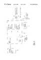
- FIG. 2is a block diagram of a product information display system, also in accordance with the present invention.
- FIG. 3is a block diagram of the system controller shown in FIGS. 1 and 2;
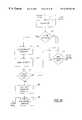
- FIG. 4is a block diagram of one of the area controllers shown in the system of FIG. 2;
- FIG. 5is an illustration of the format of the binary word that is used for communication between the area controller and one of the electronic display tags shown in the systems of FIGS. 1 and 2;
- FIG. 6is a schematic diagram of an implementation for the electronic display tag shown in the systems of FIGS. 1 and 2;
- FIG. 7is a schematic diagram of an alternative implementation for the electronic display tag shown in the systems of FIGS. 1 and 2;
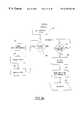
- FIGS. 8 a , 8 b and 8 care flow charts showing how the area controller of the systems of FIGS. 1 and 2 can be implemented;
- FIGS. 9 a , 9 b , 9 c and 9 dare flow charts showing how the display tag of FIGS. 1 and 2 can be implemented;
- FIG. 10is an enlarged front elevation of an implementation of a display tag for use in the system of FIGS. 1 and 2;
- FIG. 11is an enlarged front elevation of the liquid crystal display used in the tag of FIG. 10;
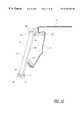
- FIG. 12is an enlarged section of an implementation of the display tag and conductor mounted on a shelf rail.
- FIG. 13is a front perspective view of the implementation shown in FIG. 12;
- FIG. 14is a front elevation of a display tag arrangement for display racks of the type used to display products in blister packs.
- FIG. 15is a front elevation of a display tag arrangement for multiple product bins in a warehouse.
- the present inventionhas application in a variety of article-information display environments. These environments include, among others, grocery stores, hardware stores, auto-parts stores, warehouses, and other establishments where variable article information is displayed at remote locations.
- the present inventionis particularly advantageous when it is used in a large store where there may be as many as 50,000 different items of merchandise placed on shelves throughout the store, and thousands of prices may change each week.
- Such an environmentis typical in a retail grocery store, and it is this context that the present invention will be described.
- This inventionis also particularly useful in warehouses containing numerous bins of small parts that are coded or marked with other types of identifications which are difficult to read.
- FIG. 1depicts part of a retail store including a product information display system arranged according to a preferred embodiment of the present invention.
- the systemincludes a plurality of display tags 20 disposed along the front rails 22 of the store's multiple display shelves 24 .
- the prices, descriptions and/or special information for all the productsare displayed on the front edges of the shelves, near the respective products.
- certain applicationsmay require a display tag 20 to display product-related information regarding multiple products, e.g., the respective products above and below the display tag 20 , preferably each display tag 20 displays information for only one product.
- the information to be displayed at each display tag 20is provided by a system controller 28 .
- the system controller 28communicates with the display tags 20 through a shelf-mounted area controller 31 using multiple conductors C 1 , C 2 . . . C n , each of which forms a large loop to communicate with a large number of display tags 20 in a prescribed area.
- a single area controller 31services at least 1000 tags, and each loop services several hundred tags.
- Each area controller 31is contained in an enclosed housing which is mounted in a relatively hidden position on the bottom side of one of the shelves.
- the system controller 28regularly communicates with the display tags for monitoring and reporting display tag failures to the system user and for identifying service inquiries and updating the display information, e.g., with price changes.
- the display tags serviced by any one of the wire loopsare usually located on a number of different shelves.
- the length of a horizontal run of the conductor CBy limiting the length of a horizontal run of the conductor C to four feet (a typical modular shelf length), non-contiguous shelf lengths can be accommodated with the conductor C weaving across one four-foot length, below to the underlying four-foot length, etc.
- the bottom shelfis typically a single unit extending along the entire length of an aisle, and thus the conductor C preferably extends continuously along the entire length of the bottom shelf.
- FIG. 1also illustrates a communication link 32 between the system controller 28 , an in-store computer and check-out scanners (not shown in FIG. 1 ).
- This link 32is also used by the system controller to receive update price information from the store computer (not shown).
- the same computersupplies data to both the tags and the scanners so that a new price for a particular product is updated in the display tag 20 at the same time the price is sent to the check-out scanners, thereby ensuring that the price displayed on the display tag 20 for the product is the same as the price displayed for and charged to the customer at the check-out scanner.
- FIG. 2illustrates the product information display system of FIG. 1 in block form.
- the systemincludes a plurality of area controllers 31 coupling the system controller 28 to various sets of display tags 20 .
- Each set of display tags 20is associated with one of the multiple wire loops C 1 -C n connected to each area controller 31 .
- the area controllers 31communicate with the tags 20 using a conventional modulation protocol such as amplitude-shift-keying (ASK), which is a binary form of amplitude modulation.
- ASKamplitude-shift-keying
- Other communication schemes, such as frequency shift keying (FSK) or phase modulationcan be used instead of ASK if desired.
- Communication between the area controllers 31 and the system controller 28is effected using a conventional serial two-way communication protocol, preferably a network interface compatible with the RS422 or RS485 standard.
- Each of the area controllers 31is powered by a d-c. power supply within the system controller 28 .
- the area controllers 31By controlling the display tags 20 through the area controllers 31 , several advantages are realized. For instance, the communication speed between the system controller 28 and the display tags 20 is increased (because it is not necessary for the system to talk to each tag), the processing power required in the system controller 28 is decreased, and a level of modularity is provided for expanding use of the display tags 20 . Further, use of the area controllers 31 significantly reduces the cost of the system by avoiding the need for an RS485 type interface at each tag.
- Both the tags and the area controllersstore data and with their interactive communications check each other as part of the auditing and failure identification system. There is redundant power back-up with a battery in the system controller and in each area controller. The cost of individual tags is reduced because certain of the electronics in the area controller does not have to be duplicated in thousands of tags, and there is more flexibility for special display messages.
- the system of FIG. 2also includes an in-store computer 40 which communicates with a remotely located central office 42 using a modem.
- the in-store computer 40provides a database of information, received from the central office 42 (or from a scanner controller), for all the merchandise in the store.
- the databaseis used to link each product with a physical-location address, an alpha-numeric (or UPC) description, a price, and a unit cost and general inventory information.
- the databasemay be accessed for the check-out scanners 44 as well as the system controller 28 . Changes in the database of the in-store computer 40 are generally initiated by updates received from the central office, but database changes producing display changes can also be made directly at the in-store computer 40 .
- the system controller 28After receiving the product data from the in-store computer 40 , the system controller 28 selects the desired display information and associated display tag address, and converts this display information into a data stream for transmission to the appropriate area controller 31 . The area controller 31 then forwards this information to the particular wire loop C 1 -C n which includes the designated tag 20 .
- the printer 46may be used to make hard copies of the desired displays, for example on regular or transparent paper, for insertion into a shelf rail at any locations not covered by the electronic tags 20 .
- the printercan also be used to generate store or system reports.
- the battery back-up unit 48is used to maintain system integrity during periods of power interruption.
- the system controller 28may be implemented using a personal computer 28 (such as a 486 or equivalent) containing a number of network boards configured for serial two-way communication with the area controllers 31 . Or communication can be accomplished with conventional RS422/RS485 interfaces or equivalent.
- the system controller 28also contains a conventional hard-drive 62 for programs, protocols, addresses and storage, and power and data distribution circuits 64 a , 64 b , etc. for all the area controllers 31 in the system.
- Each distribution circuit 64transmits and receives serial data over one set of lines 68 and sends d-c. power over another set of lines 70 .
- battery 72is used as the power source, with an a-c.-powered battery charger 74 activated as necessary to maintain an adequate charge on the battery 72 .
- the battery 72is the primary power source for the area controllers 31 , emergency power for the system is also provided from this battery.
- Each area controller 31receives the data from the outputs of the network boards of the system controller 28 and translates the data into an information/power signal that is applied to one of the conductors C 1 -C n for transmission to the display tags.
- Data transmission to the tagsis typically at 1200 baud using ASK.
- Each area controller 31includes a network interface circuit 80 such as an RS485 transceiver circuit, a microcomputer or microprocessor (MPU) 82 , a memory 84 , and a plurality of transceiver circuits 86 , one for each of the conductors C 1 -C n .
- the microprocessor 82uses the transceiver circuits to receive the product data from the network interface 80 and determines on which conductor the display tag address resides.
- the microprocessor 82then generates an information signal for modulating an a-c. power signal supplied to the selected conductor so that the information signal will be conveyed to the desired display tag 20 .
- the nominal frequency of the power signal carried by each of the conductors C 1 -C nis 50 KHz.
- Each transceiver circuit 86 in the area controller 31includes a digital-to-analog converter 88 , a voltage-to-current driver circuit 90 , and a phase-locked loop (PLL) circuit 92 or equivalent detector circuitry.
- the digital-to-analog converter 88converts the digital information signal from the microprocessor 82 into analog form. Alternatively, a straight analog communication scheme with an analog oscillator can be used.
- the resulting analog signalis connected to the input of the driver circuit 90 , which converts the analog voltage into a proportional current for driving the display tags 20 via one end of one of the conductors C 1 -C n . The other end is terminated at ground for the area controller.
- the area controller 31also includes a transformer 87 whose primary is in series with one of the conductors C 1 -C n .
- the transformer 87produces a secondary voltage proportional to the primary current which is fed back to the voltage-to-current converter 90 and to the PLL input.
- the PLL circuit 92senses the presence or absence of the known sub-harmonic frequency signal from any of the tags. This signal is then decoded by the MPU 82 .
- a superheterodyne receivermay be used as an alternative to the PLL.
- a d-c. to d-c. converter and battery charger 94is used to charge a back-up battery 96 , which provides at least one hour of operating power to the area controller 31 .
- the charger 94receives its power from the 24-volt d-c. supply 72 in the system controller 28 (FIG. 3 ).
- the area controller 31is able to provide uninterrupted power and control to the display tags 20 for at least one hour. This period of time should be sufficient to permit repair, and if more time is needed the battery 96 can be backed up as needed, or the tags can be put in a sleep mode, as described in more detail below.
- the location of the input end of the conductoralternates between the tag and bottom of vertically adjacent shelves. This causes any radiated signals from the loops on adjacent shelves to cancel each other, so that the overall system does not cause any radiation emission problems.
- the alternate phasing of the loopsalso reduces cross-talk between adjacent conductors and reduces the susceptibility of the system to radiation from other sources.
- FIG. 5illustrates a preferred type of serial communication between one of the area controllers 31 and the associated display tags 20 .
- the serial data sent from the area controller to the display tagsmay include a tag address (“select one tag”) or a selected group of tags, an “all tag” command to which all tags respond when they recognize a special address, a “load selected” command which includes a particular tag address, a “load subroutine” command which loads a set of data in the unused portion of a particular tag's memory, a “service inquiry” command to query whether any tags need to communicate with the area controller, a “reset” command for resetting a particular tag, a “request checksum” command which is responded to by a tag sending a checksum corresponding to its down-loaded data (this is a price verification routine), a “request data” command which invites a tag to send selected data to the area controller, or “sleep” or “wake-up” commands which respectively remove and apply on-board power to certain circuits for
- the serial data sent from the display tag to the area controllerincludes requests and responses.
- An “Ack” responsemeans that the tag received the communication from the area controller, and a “Nak” response means that the communication failed.
- a “Request”is an affirmative response to a service invitation to send data to the area controller, and “Data” is the data sent in response to the area controller requesting the data.
- FIGS. 6 and 7illustrate two different embodiments of the display tag 20 . Common reference numerals are used for common components in the two diagrams. The differences between the embodiments of FIGS. 6 and 7 concern the type of inductor 110 (or 110 ′) utilized and the signal processing performed by a rectification circuit 114 (or 114 ′), a power supply circuit 116 (or 116 ′), and a signal conditioning circuit 118 (or 118 ′).
- a pick-up coil or inductor 110(or 110 ′) is located close enough to the conductor C to cause the changing electromagnetic field around the conductor C to induce a corresponding current in the inductor 110 .
- This induced currentprovides the display tag 20 with both the necessary operating power and the data for the display without requiring any physical contact between the display tag 20 and the conductor C.
- the inductive coupling of both power and information signals to the tagseliminates the need for batteries in the tags and for physical contacts between the tags and the wire loop. This minimizes the cost of the tags, and also avoids problems caused by contact corrosion and electrostatic discharges.
- the preferred embodiment of the pick-up coil 110is a single coil with a full wave bridge rectifier as shown in FIG. 6, but if desired two separate windings may be used, with one winding connected for data decoding (or demodulation) and the other winding connected for supplying power to the display tag.
- the pick-up coil in the preferred embodimentcan be implemented by winding 43 turns of #32 enameled wire in a channel molded into the outer periphery of the tag housing, as described in more detail below in connection with FIGS. 12 and 13.
- a capacitor 112is connected in parallel with the inductor 110 to form a parallel tuned circuit that is responsive to a particular range of frequencies centered about the carrier frequency transmitted by the area controller. This resonant circuit maximizes voltage gain and significantly improves coupling efficiency.
- the current induced in the coil 110is sent through a full-wave rectifier 114 to provide a positive input to a power supply circuit 116 and a signal conditioning circuit 118 .
- the output of the voltage regulator 124which is connected to a capacitor 126 , provides operating power (V cc ) for the display tag 20 .
- the signal conditioning circuit 118is preferably a Schmidt buffer which improves the rise and fall times and the signal-to-noise ratio of the signal from the coil 110 .
- the circuit 118can be implemented using a commercially available buffer having hysteresis control.
- the induced currentis produced in a pick-up coil formed by a center-tap inductor 110 ′.
- the ends of the inductor 110 ′are connected to a pair of rectifying diodes 114 ′, 114 ′′ to provide a full-wave rectified positive signal for the circuit 118 ′.
- the diode 114 ′′can be removed (replaced by a wire) for an operable half-wave rectified signal.
- the power supply circuit 116 ′draws current from the center-tap of the inductor 110 ′ and includes a voltage regulator 124 and a capacitor 126 at its output for providing operating power (V cc ) for the display tag 20 .
- the power supply circuit 116 ′is connected to common (ground) for returning current through the diodes 114 ′, 114 ′′ to the inductor 110 ′.
- the output of the signal conditioning circuit 118 or 118 ′is pulse-extended using a monostable vibrator circuit 142 .
- the output of the circuit 142is monitored by a microcomputer (CPU) 146 for demodulating the data.
- a universal-asynchronous-receiver-transmitter (UART) 144converts the sequential digital pulses from the circuit 142 into parallel format for use by the CPU 146 , and vice-versa.
- An oscillator 147provides the operating clock signal for both the UART 144 and the CPU 146 .
- a manually adjustable trimming resistor 149replaces the normally used crystal or ceramic resonator, but produces a much larger variation in oscillator frequency from tag to tag.
- This variationis compensated for by synchronizing the oscillator frequency to the carrier frequency, thereby permitting the use of an R-C oscillator and eliminating the cost and size of a crystal.
- the oscillator cyclesare counted during each half cycle, or multiple, of the rectified main primary frequency (50 KHz wave rectified to 100 KHz wave). This count is then used to generate internal frequencies that may be needed for communications.
- the buffer 118( 118 ′), the monostable vibrator circuit 142 and the UART 144 may not be required, since many microcomputers have input ports which can accommodate and process analog signals directly. With such microcomputers, the UART-related functions are implemented in software.
- the microcomputer (CPU) 146uses conventionally configured operating memory, including ROM 148 and RAM 150 , and an LCD display memory 152 , 154 for maintaining an assigned display set on an LCD display 156 and communicating with the area controller 31 .
- the display 156is preferably driven using a conventional two-row display driver circuit 158 controlled by the CPU 146 .
- a pair of membrane switches 166are accessible on the outside surface of the tag housing.
- Buffers 168each having a conventional input pull-up resistor or current source, are connected to the switches 166 , and the outputs of the buffers 168 , are supplied to the CPU 146 .
- CMOS circuitryis preferred for the tags 20 . This permits the power draw from the conductor C to be maintained under 25 milliwatts per tag.
- a custom CMOS integrated circuit (IC) mounted on the printed circuit boardcontains all of the electronics except the display, the tuned circuit, the FET 159 , the capacitor 126 and the switches 166 , and requires very little power to operate.
- the display tag 20can transmit signals to the area controller 31 by an impedance modulation scheme which changes the impedance of the tag circuit that is inductively coupled to the conductor C, thereby changing the impedance of the loop formed by the conductor C.
- This impedance changeis detected by the phase-locked loop 92 in the area controller 31 .
- the UART 144turns on a JFET connected in parallel with the resonant circuit 110 , 112 .
- the conduction of the JFET 159shorts the capacitor 112 , thereby changing the impedance of the circuit coupled to the conductor C.
- a signalmay be induced in the conductor C at a frequency which is a sub-harmonic of the a-c. power signal which serves as the carrier signal.
- the sub-harmonicsare preferably generated by rendering the JFET 159 conductive during odd-number half cycles of the a-c. power signal in the wire loop. For example, if the JFET 159 is turned on during only one half cycle out of three successive half cycles of the a-c. power signal in the wire loop, the frequency of the signal induced in the loop by the tag is 2 ⁇ 3 the frequency of the a-c. power signal. Naturally occurring sub-harmonics do not occur at odd fractions of the primary frequency, and thus will not interfere with the signal artificially generated by the impedance modulation.
- the frequency of the induced signalis (2F c )/N, where F c is the carrier frequency and N is a positive odd integer.
- the half cycle count with full wave rectificationis 2F c .
- Nis 3 and the sub-harmonic is 2 ⁇ 3 F c .
- a bit of datais represented by a burst of one or more cycles of the artificially generated sub-harmonic signal. Successive bursts, of course, must be separated by periods of no impedance modulation to enable each separate burst to be detected as a separate bit of data.
- the a-c. power signalcan be modulated at either of two different artificially generated frequencies.
- a “1”can be represented by a signal having 2 ⁇ 3 the frequency of the a-c. power signal
- a “0”is represented by a signal having 2 ⁇ 5 the frequency of the a-c. power signal.
- This impedance modulation techniqueis a way of transmitting data from the tag to the area controller in a manner which is virtually powerless. The only consumed power is that needed to turn the FET on and off.
- Signals induced in the wire loop by impedance modulation in a tagare detected in the phase-locked loop 92 in the transceiver 86 of the area controller 31 .
- the area controller's micro-processor 82then decodes this information and determines which tag is the source of this signal.
- the area controllerthen processes this data for functions controlled by the area controller such as check sums for price verification or passes information onto the system controller 28 .
- the microcomputer 146 in the tagincludes I/O buffers 160 and capacitors 162 for storing an assigned the bits of charges representing display tag address.
- the microcomputer 146stores the down-loaded address for the tag by writing the address to the I/O buffers 160 .
- the ports on the other side of the buffers 160are connected to the capacitors 162 .
- the addressis preserved by the charge on the capacitors 162 for a certain period of time. If desired, alternative means of temporary storage may be used.
- the battery 96 in the area controller 31maintains all the tags serviced by that controller in normal operation for a selected time interval following a power failure. At the end of that time interval, which is determined by the MPU 82 in the area controller, the MPU 82 generates a signal which causes the CPU 146 in each tag to turn off the tag display. All the address and product information remains stored in the tag memory, including the capacitors 162 . This second stage of the power-failure mode of operation is continued for a specified period of time after which the data stored in each tag's RAM 148 and ROM 150 is erased, and only the tag addresses are preserved by the battery backup in the area controller.
- the capacitors 162When the battery is exhausted, the capacitors 162 then preserve the addresses as long as the charge on the capacitors 162 is sustained. In the event a tag is removed temporarily from a rail, the capacitors 162 will maintain the address for a few minutes so that it is not necessary to manually reprogram the tag when it is reinstalled, as long as the address is maintained. This multi-level approach provides extensive safeguards to a variety of power-failure conditions.
- Address programming for each tag 20is accomplished by entering the start-up mode.
- the first address and associated product information datais generated by the system controller and fed to the area controllers for transmission to the display tags. This product information data appears on all the display tags running in the start-up mode.
- An installerthen manually triggers a membrane switch 166 on the particular display tag which is to be identified by the first address, and which is to display the product information data associated with that address and the shelf product adjacent to it.
- the CPU 146captures the address and associated product information data and exits the start-up mode, thereby initiating the normal run mode in the display tag.
- the display tagwill continuously display the product information data which is contained in the memory of the display tag until it receives an address which matches its stored address, at which time it will update the display in accordance with the information data immediately following the received address.
- the display tagUpon exiting the start-up mode, the display tag sends a confirmation signal back to the system controller 28 via the conductor C and area controller 31 to inform the system controller that the first address has been captured by the appropriate tag.
- the system controllerthen sends the next address and associated product information data to the display tags. This new product information data is again displayed on all the tags that remain in the start-up mode. Visual inspection to make sure this adjacent shelf product agrees with the tag displayed information and manual triggering of successive display tags continues until all the display tags have captured addresses and display data. After any given display tag has captured an address during initialization, the system controller is able to update the information in that tag at any time.
- Block 180 of FIG. 8 adepicts this first step.
- the MPU in the area controllerdetermines if all tags on the system have been initialized (block 186 ). If the data has been sent for all the tags, the step of down-loading is complete and this routine ends, as depicted at block 188 .
- the initial pass through block 186will lead to the step of block 190 in which the MPU broadcasts the information for the next tag associated with the area controller.
- the MPUwaits for one of the tags to respond. If the response is an “Ack” (block 194 ), flow proceeds to block 196 where the MPU increments the data buffer for initializing the address for the next tag and then proceeds back to block 186 . If the response is not an “Ack” (block 194 ), flow proceeds to block 198 where the MPU determines whether a tag has responded with a “Nak”. A “Nak” indicates an error which is handled in block 199 , and then flow returns to block 188 . If it is neither an “Ack” nor a “Nak”, the system tries to load the tag again until it times out. It then reports the error and proceeds to the next tag. This continues until all the tags are initialized with the appropriate address and product information.
- FIG. 8 billustrates how each area controller operates once the step of down-loading is complete.
- Blocks 200 , 202 and 204respectively depict starting the normal operation program, phase locking to the 50 KHz power signal and broadcasting to the tags for a service request.
- the area controllerdetermines if one of the tags has responded to the service request. If there is a response, the request for service is handled as shown at block 208 . If there is not a response, the area controller determines that there is no tag requesting service and flow proceeds to block 210 where a communication check for each tag in the system is begun. At block 210 , the next tag is selected. At blocks 212 , 214 and 216 , a cyclic redundancy code (CRC) is requested from this next tag, returned by the tag and analyzed by the area controller's MPU to ensure that the tag data is correct and the tag is properly communicating. To ensure the integrity of the communication, the MPU preferably uses the “Load Subroutine” command to send data to the tag changing the loaded database. This forces the tag to send back a new CRC, which the area controller checks and verifies.
- CRCcyclic redundancy code
- FIG. 9 aa flow chart shows how the display tag is programmed to initialize the tag with an address and to bring the tag “on-line”.
- This programming modestarts at block 230 and proceeds to block 232 where the microprocessor in the tag performs a power-on self-test (block 232 ) involving memory and register checks.
- block 232the microprocessor in the tag performs a power-on self-test (block 232 ) involving memory and register checks.
- a testis performed to determine if the self-test passed. If not, flow proceeds from block 236 to 234 where the tag reports the error via the visual display.
- the tagmonitors the power signal on the conductor to determine whether or not the tag has received a data packet. If a packet is received, flow proceeds from block 246 to block 248 where the tag stores the embedded address. Within the packet is the product information. From block 248 , flow proceeds to blocks 250 and 252 where the tag stores the information to be displayed and displays that information on the tag's visual display.
- the tagdetermines if the initialization key (switch) has been manually pressed. If not, flow returns to block 246 to continually look for a packet transmitted to this tag. From block 254 , flow proceeds to block 256 in response to detecting that the initialization key switch has been manually pressed.
- the tag address received within the packetis adopted by the tag. From block 256 , flow proceeds to block 258 where the tag goes on-line by sending an “Ack” communication to the area controller. At block 260 , the tag is depicted as going on-line. This ends the program mode for initializing the tag.
- the tagAfter initialization, the tag is ready for normal operation, which is depicted by the flow chart in FIG. 9 c .
- This flow chartbegins at block 262 and block 268 where the tag immediately begins monitoring the conductor to determine whether an information pack has arrived from the area controller. If such a packet has arrived, flow proceeds from block 268 to block 270 where the tag compares the address embedded in the information packet with the address of this tag to determine if the packet is for this tag. If it is not for this tag, the tag determines whether the packet represents a broadcast to all tags (such as “STORE IS CLOSING”), as depicted at block 272 . If the information packet is for this tag, flow proceeds from block 270 to blocks 274 and 278 where the tag identifies and executes the necessary action associated with the received information packet.
- STORE IS CLOSINGsuch as “STORE IS CLOSING”
- flowproceeds to blocks 274 and 278 if the packet is associated with a broadcast for all tags (the “All tags” command).
- flowproceeds to block 280 in response to the tag determining that a packet has not arrived over the conductor.
- the tagperforms a test to determine whether a manual button sequence has been entered. If such a sequence has not been entered, flow returns to block 268 . If a manual button has been depressed, flow proceeds from block 280 to blocks 282 and 284 where the tag determines if the sequence is one of the valid sequences. If it is not a valid sequence, flow returns to block 268 . If it is a valid sequence, flow proceeds from block 284 to block 286 where the command is executed. From block 286 , flow proceeds to block 288 where the buffer is cleared and flow returns to block 268 .
- sequencesare binary numbers entered by depressing membrane switches representing “0” or “1”.
- Valid sequencesinclude binary sequences corresponding to requests for: resetting the tag; entering the cursor mode (FIG. 9 c ); verifying the status of the tag and verification codes. Clearing the software buffer which stores the binary digits entered through the switches occurs after a time-out.
- FIG. 9 da flow chart for implementing the cursor mode for the display tag is shown. This routine is executed in response to a valid manually-entered sequence.
- the cursor modebegins at blocks 290 , 292 and 294 , where the tag sets up the display with a cursor position movable by one of the buttons, the scroll button.
- the tagperforms a test to determine whether a scroll button has been depressed. If so, flow proceeds to block 302 where the tag changes (or scrolls through) to the next cursor code position. From block 302 , flow returns to blocks 296 and 298 where the tag performs yet another test to determine if the scroll button has been depressed. This continues with the display code position being changed with each depression of the scroll button (switch).
- the current cursor positionis equated with a package (or function), as indicated at block 306 .
- the current position of the cursoris returned to the area controller thereby selecting the associated data block.
- the area controllermay optionally await a verification to be entered into the buttons on this tag before acting on selected data.
- one membrane switchis used to select a displayed code and position the cursor to a selected display character position, and the other switch is used to terminate the cursor mode, selecting the last position of the cursor.
- Such an implementationis ideally used for reordering products and alerting the system controller as to the status of the product for the associated tag.
- FIG. 10illustrates a front view of the tag 20 shown in the previously-discussed figures and FIG. 11 shows the details of the face of the LCD display.
- the printed circuit board or flex circuit carrying the electronic components for the tag 20is concealed within the tag housing 311 .
- the front wall of the housingforms a rectangular aperture for the LCD display, which includes four seven-segment characters 313 , a decimal point 314 , an eight-segment units identifier 315 , and a “for” annunciator 316 for displaying prices for quantity purchases; an 18-character alpha-numeric display 317 (either 5 ⁇ 7 matrix or 14 segments) for product descriptions; and a zone 318 with a combination of characters to display cost per unit.
- a display driversuch as FD2258f/FC2258A/FC2258K manufactured by Fuji Electric is used to translate the parallel data from the memory into the conventional drive signals for the LCD display.
- the displayis shown to be of the LCD type, but LED's or other types of electronically controlled displays can be used.
- a clear filmmay be bonded to the front of the tag housing to cover the display window.
- FIGS. 12 and 13illustrate a preferred arrangement for mounting the display tags 20 on a conventional shelf 24 which includes a depending rail 22 formed as an integral part of the shelf.
- An auxiliary rail 320is snapped into the shelf rail 22 and extends continuously along the full length of the shelf for receiving both the display tags 20 and the conductor C.
- the auxiliary rail 320is designed so that the display tag 20 and the conductor C may be snapped into place anywhere along the length of the rail.
- the insulated conductor Cis mounted in two channels 321 and 322 formed near the top and bottom of the rear wall of the rail 320 .
- the tagis received in a channel formed in the front side of the rail 320 .
- the tagis recessed inside, and held in place by, a pair of flanges 323 and 324 so that the tag does not protrude from the rail.
- the upper flange 323is flared outwardly at a slight angle so that it can be bent upwardly and outwardly for installation and removal of tags from the front of the rail.
- a pair of rearwardly projection flanges 325 and 326hold the rail 320 in place on the shelf rail 22 .
- the pick-up coil 110is wound around the periphery of the tag housing 311 in a channel 328 formed in all four edges of the housing.
- the coil segments located in the top and bottom sections of the channel 328are in close proximity to the two segments of the conductor C on the rear side of the rail 320 .
- the coilis electromagnetically coupled to both segments of the conductor C.
- a single conductor Cis snapped into the top channel 321 of the rail 320 , spans the length of the store shelf, and then loops to the bottom channel 322 of the rail 320 and spans the length of the shelf rail again.
- FIG. 14illustrates a display tag arrangement for products which are displayed on racks rather than shelves.
- This type of display rackis commonly used for products which are packaged in blister packages.
- the rackincludes multiple rods 330 , each of which supports multiple packages. A package can be removed from the rod by simply sliding the package off the forward end of the rod.
- a rail 320is mounted directly above the rods 330 , and contains a separate display tag 20 for each of the rods 330 .
- the conductor Cis fasten to the rear side of the rail 320 in the same manner described above in connection with FIGS. 12 and 13.
- FIG. 15illustrates the use of the electronic display tag system of invention in a warehouse environment.
- Many warehousescontain numerous bins containing many different kinds of small articles which are difficult to identify from the markings on the articles themselves.
- FIG. 15contains a diagrammatic illustration of four such bins 340 .
- a rail 320is mounted directly beneath each row of bins, and contains a separate display tag for each bin.
- the conductor Cis mounted on the rear side of each of the rails 320 .
Landscapes
- Engineering & Computer Science (AREA)
- Theoretical Computer Science (AREA)
- Human Computer Interaction (AREA)
- Physics & Mathematics (AREA)
- General Engineering & Computer Science (AREA)
- General Physics & Mathematics (AREA)
- Control Of Indicators Other Than Cathode Ray Tubes (AREA)
Abstract
Description
Claims (21)
Priority Applications (3)
| Application Number | Priority Date | Filing Date | Title |
|---|---|---|---|
| US08/647,664US6249263B1 (en) | 1993-09-03 | 1996-05-15 | Article-information display system using electronically controlled tags |
| US09/309,119US6271807B1 (en) | 1993-09-03 | 1999-05-10 | Method of initializing, controlling and updating electronic display tags and related controller therefor |
| US09/309,082US6266052B1 (en) | 1993-09-03 | 1999-05-10 | Power and information distribution system for article display or storage areas and related method |
Applications Claiming Priority (2)
| Application Number | Priority Date | Filing Date | Title |
|---|---|---|---|
| US16646893A | 1993-09-03 | 1993-09-03 | |
| US08/647,664US6249263B1 (en) | 1993-09-03 | 1996-05-15 | Article-information display system using electronically controlled tags |
Related Parent Applications (2)
| Application Number | Title | Priority Date | Filing Date |
|---|---|---|---|
| US16646893AContinuation | 1993-09-03 | 1993-09-03 | |
| US08/116,468ContinuationUS5537126A (en) | 1993-09-03 | 1993-09-03 | Article-information display system using electronically controlled tags |
Related Child Applications (2)
| Application Number | Title | Priority Date | Filing Date |
|---|---|---|---|
| US09/309,082DivisionUS6266052B1 (en) | 1993-09-03 | 1999-05-10 | Power and information distribution system for article display or storage areas and related method |
| US09/309,119DivisionUS6271807B1 (en) | 1993-09-03 | 1999-05-10 | Method of initializing, controlling and updating electronic display tags and related controller therefor |
Publications (1)
| Publication Number | Publication Date |
|---|---|
| US6249263B1true US6249263B1 (en) | 2001-06-19 |
Family
ID=22603431
Family Applications (1)
| Application Number | Title | Priority Date | Filing Date |
|---|---|---|---|
| US08/647,664Expired - LifetimeUS6249263B1 (en) | 1993-09-03 | 1996-05-15 | Article-information display system using electronically controlled tags |
Country Status (1)
| Country | Link |
|---|---|
| US (1) | US6249263B1 (en) |
Cited By (25)
| Publication number | Priority date | Publication date | Assignee | Title |
|---|---|---|---|---|
| US20020105065A1 (en)* | 2000-06-29 | 2002-08-08 | Olivier Parrault | Contact-free display peripheral device for contact-free portable object |
| US20030023505A1 (en)* | 2001-02-28 | 2003-01-30 | Eglen Jan Alan | Digital online exchange |
| US20030142062A1 (en)* | 1997-03-18 | 2003-07-31 | Christopher Turner | Printable electronic display |
| US20030156090A1 (en)* | 2002-02-20 | 2003-08-21 | Munn Jason Drury | Bistable liquid crystal display having a remote display update control |
| US20040155109A1 (en)* | 2003-02-12 | 2004-08-12 | Sears Brands, Llc | Digital assistant for use in a commercial environment |
| US20040207512A1 (en)* | 2000-12-11 | 2004-10-21 | Bastian William A. | Inventory system with image display |
| US20050140498A1 (en)* | 2000-12-11 | 2005-06-30 | Bastian William A.Ii | Inventory system with barcode display |
| US20050200559A1 (en)* | 2004-02-24 | 2005-09-15 | Fumio Koyama | Information display and information display system |
| US20060273164A1 (en)* | 2005-06-03 | 2006-12-07 | News America Marketing Properties, Llc | Product information and advertising system |
| US20070141874A1 (en)* | 2005-02-17 | 2007-06-21 | General Electric Company | Power control system and method |
| US20080052198A1 (en)* | 2006-01-30 | 2008-02-28 | Fujitsu Limited | Electronic shelf labels, electronic shelf label system server, electronic shelf label system |
| US20090254419A1 (en)* | 2008-04-03 | 2009-10-08 | Toshiba Tec Kabushiki Kaisha | Information display system, display device, and server |
| US20110153112A1 (en)* | 2007-08-10 | 2011-06-23 | Inta Holdings Pty Limited | Electrical tagging device |
| US20110154260A1 (en)* | 2009-12-17 | 2011-06-23 | Motorola Inc | Method and apparatus for displaying information in an electronic device |
| US20120062397A1 (en)* | 2010-09-13 | 2012-03-15 | Bngrotis Inc. | Traffic inferior tag recognization bus information system |
| US8893977B2 (en) | 2010-04-08 | 2014-11-25 | Access Business Group International Llc | Point of sale inductive systems and methods |
| US8910801B2 (en) | 2012-06-21 | 2014-12-16 | L & P Property Management Company | Inductively coupled product positioning system |
| US9022637B2 (en) | 2013-04-30 | 2015-05-05 | Tagnetics, Inc. | Lighted mounting apparatus |
| US9251727B2 (en) | 2012-06-21 | 2016-02-02 | L&P Property Management Company | Inductively coupled product display |
| US9275361B2 (en) | 2013-01-11 | 2016-03-01 | Tagnetics, Inc. | Out of stock sensor |
| US9364100B2 (en) | 2012-06-21 | 2016-06-14 | L & P Property Management Company | Inductively coupled shelving system |
| US20170109115A1 (en)* | 2015-10-16 | 2017-04-20 | Omnivision Technologies, Inc. | Multi-projector display box |
| US11107136B2 (en) | 2016-10-21 | 2021-08-31 | Brian Conville | Management of products and dynamic price display system |
| JP2024509677A (en)* | 2021-03-09 | 2024-03-05 | エスエーエス-イマーゴタグ・ゲゼルシャフト・ミト・ベシュレンクテル・ハフツング | Bus systems and supporting devices with such bus systems |
| US12445318B2 (en) | 2021-03-09 | 2025-10-14 | Vusiongroup Gmbh | Bus system and support device comprising such a bus system |
Citations (94)
| Publication number | Priority date | Publication date | Assignee | Title |
|---|---|---|---|---|
| US3086308A (en) | 1959-06-29 | 1963-04-23 | Westlake G Ternouth | Shelf-edge sign |
| US3256512A (en) | 1962-06-05 | 1966-06-14 | North Electric Co | Remote sign control system |
| US3622992A (en) | 1969-10-15 | 1971-11-23 | Honeywell Inc | Supervision and control apparatus with selective display |
| US4002866A (en) | 1974-04-19 | 1977-01-11 | Illinois Tool Works Inc. | Electric switches |
| US4139149A (en) | 1977-08-31 | 1979-02-13 | Ncr Corporation | Display system |
| EP0006691A1 (en) | 1978-06-02 | 1980-01-09 | Peter Harold Cole | Object identification system |
| US4500880A (en) | 1981-07-06 | 1985-02-19 | Motorola, Inc. | Real time, computer-driven retail pricing display system |
| US4521677A (en) | 1983-12-02 | 1985-06-04 | Sarwin Herbert S | Product control system for supermarkets and the like |
| US4525713A (en) | 1983-03-01 | 1985-06-25 | Lockheed Electronics Co., Inc. | Electronic tag identification system |
| US4603495A (en) | 1984-09-19 | 1986-08-05 | Stevens John K | Alphanumeric display modules |
| US4654514A (en) | 1984-09-10 | 1987-03-31 | Texas Instruments Incorporated | Product information system using hand-held unit with code reader |
| US4702558A (en) | 1983-09-14 | 1987-10-27 | The Victoria University Of Manchester | Liquid crystal information storage device |
| US4745404A (en) | 1985-11-23 | 1988-05-17 | Edding Ag | Display device for planning purposes |
| US4766295A (en) | 1987-03-02 | 1988-08-23 | H.E. Butt Grocery Company | Electronic pricing display system |
| WO1988006773A1 (en) | 1987-02-26 | 1988-09-07 | Gabriel Ordonez | Retail display system |
| US4791739A (en) | 1986-04-28 | 1988-12-20 | Esselte Meto International Gmbh | Price board |
| US4796028A (en) | 1986-04-29 | 1989-01-03 | Angewandte Digital Elektronik Gmbh | Apparatus for bidirectional data transmission |
| US4821291A (en) | 1986-09-22 | 1989-04-11 | Stevens John K | Improvements in or relating to signal communication systems |
| US4833338A (en) | 1988-08-04 | 1989-05-23 | The Boeing Company | Ferroresonant regulator for inductively coupled power distribution system |
| US4833337A (en) | 1986-10-16 | 1989-05-23 | Sundstrand Corporation | Inductive coupled power system |
| US4864633A (en) | 1987-03-02 | 1989-09-05 | La Telemecanique Electrique | Inductive device for the rapid exchange of data between two data carriers |
| US4879756A (en) | 1986-09-22 | 1989-11-07 | Stevens John K | Radio broadcast communication systems |
| US4937586A (en) | 1986-09-22 | 1990-06-26 | Stevens John K | Radio broadcast communication systems with multiple loop antennas |
| US4941201A (en) | 1985-01-13 | 1990-07-10 | Abbott Laboratories | Electronic data storage and retrieval apparatus and method |
| US4939861A (en) | 1987-12-28 | 1990-07-10 | Telepanel, Inc. | Shelf tag moulding attachment assembly |
| US4955000A (en) | 1986-07-17 | 1990-09-04 | Nac Engineering And Marketing, Inc. | Ultrasonic personnel location identification system |
| EP0243810B1 (en) | 1986-04-28 | 1990-10-03 | Esselte Meto International Produktions Gmbh | Advertisement or price board |
| US4962466A (en) | 1987-03-27 | 1990-10-09 | Viscom Systems, Inc. | Electronic product information display system |
| JPH02287591A (en) | 1989-04-28 | 1990-11-27 | Hitachi Maxell Ltd | Rack tag display system |
| WO1990014630A1 (en) | 1989-05-16 | 1990-11-29 | Rest Manufacturing, Inc. | Remote electronic information display system |
| US5019811A (en) | 1984-10-15 | 1991-05-28 | Unigrafic Ag | Device for marking edges of shelves |
| WO1991008539A1 (en) | 1989-12-01 | 1991-06-13 | Braennstroem Roland | An electronic price information system |
| WO1991011063A1 (en) | 1990-01-19 | 1991-07-25 | Bertin & Cie | Bidirectional inductive transmission of data with slave station supplied by the master |
| GB2240416A (en) | 1990-01-26 | 1991-07-31 | Esselte Meto Int Gmbh | Electronic price display systems |
| US5054112A (en) | 1988-03-16 | 1991-10-01 | Seiko Instruments Inc. | Electronic data collection system |
| EP0463341A1 (en) | 1990-06-22 | 1992-01-02 | British Aerospace Public Limited Company | Digital data transmission with simultaneous transmission over a single line |
| US5111196A (en) | 1987-03-23 | 1992-05-05 | Esl, Inc. | Electronic information display module and connector therefor |
| GB2249854A (en) | 1990-10-17 | 1992-05-20 | Sainsbury J Plc | Electronic labels |
| WO1992009054A1 (en) | 1990-11-16 | 1992-05-29 | Patrick Nitschke | Device for providing information about an article and information processing system using same |
| EP0497533A2 (en) | 1991-01-28 | 1992-08-05 | NCR International, Inc. | Electronic price display apparatus |
| JPH04303294A (en) | 1991-03-29 | 1992-10-27 | Teraoka Seiko Co Ltd | Merchandise information display |
| US5160920A (en) | 1990-12-07 | 1992-11-03 | International Business Machines Corporation | Fail safe display for shelf labels |
| US5172314A (en) | 1991-05-03 | 1992-12-15 | Electronic Retailing Systems International | Apparatus for communicating price changes including printer and display devices |
| GB2257278A (en) | 1991-06-28 | 1993-01-06 | Esselte Meto Int Gmbh | Security and information display. |
| WO1993005456A1 (en) | 1991-09-10 | 1993-03-18 | Electronic Retailing Systems International | Localizing power faults in an electronic pricing display system |
| US5198644A (en) | 1989-05-05 | 1993-03-30 | Diablo Research Corporation | System for display of prices and related method |
| WO1993011509A1 (en) | 1991-12-04 | 1993-06-10 | Citizen Watch Co., Ltd. | Data carrier |
| US5241467A (en) | 1992-04-30 | 1993-08-31 | Ers Associates Limited Partnership | Space management system |
| US5241657A (en) | 1990-02-05 | 1993-08-31 | Fine Brandt J | Information display system |
| DE4206793A1 (en) | 1992-03-04 | 1993-09-09 | Esselte Meto Int Gmbh | Cassette for displaying prices of goods for sale - has compartments which can receive replaceable labels which are easily removed |
| US5245534A (en) | 1991-09-10 | 1993-09-14 | Ers Associates Limited Partnership | Electronic tag location systems |
| GB2266401A (en) | 1992-03-25 | 1993-10-27 | Clares Equip Ltd | Shelf label holder. |
| US5260701A (en) | 1990-01-19 | 1993-11-09 | Societe Bertin & Cie | Bidirectional inductive transmission of data with slave station supplied by the master |
| WO1994000895A1 (en) | 1992-06-22 | 1994-01-06 | Pricer Norden Ab | Connection using zebra strip |
| EP0423188B1 (en) | 1988-07-06 | 1994-01-19 | Esselte Meto International GmbH | Arrangement for marking system |
| US5293400A (en) | 1990-05-18 | 1994-03-08 | Centre National Du Machinisme Agricole, Du Genie Rural, Des Eaux Et Des Forets | Contactless linking device for interconnecting data bus sections |
| DE4237467A1 (en) | 1992-11-06 | 1994-05-11 | Esselte Meto Int Gmbh | Electronic cash register for use in shop - displays prices on main display for customer, and has LCD screen for indicating product information for salesperson |
| WO1994011835A1 (en) | 1992-11-13 | 1994-05-26 | Pricer Norden Ab | Solar switch |
| WO1994011833A1 (en) | 1992-11-13 | 1994-05-26 | Pricer Norden Ab | Monitoring module |
| WO1994011834A1 (en) | 1992-11-13 | 1994-05-26 | Pricer Norden Ab | Receiver polling |
| EP0604382A2 (en) | 1992-12-22 | 1994-06-29 | Electronic Retailing Systems International, Inc. | Technique for communicating with electronic labels in an electronic price display system |
| WO1994017615A2 (en) | 1993-01-25 | 1994-08-04 | Electronic Retailing Systems International, Inc. | Electronic price display system with data bus isolation |
| US5345231A (en) | 1990-08-23 | 1994-09-06 | Mikron Gesellschaft Fur Integrierte Mikroelectronik Mbh | Contactless inductive data-transmission system |
| GB2275807A (en) | 1993-02-17 | 1994-09-07 | Clares Regisbrook Systems | A display |
| US5348485A (en) | 1993-04-12 | 1994-09-20 | Electronic Retailing Systems Int'l Inc. | Electronic price display system with vertical rail |
| WO1994023381A1 (en) | 1993-04-05 | 1994-10-13 | Pricer Ab | System for electronic price labels |
| US5374815A (en) | 1993-03-15 | 1994-12-20 | Electronic Retailing Systems Int'l Inc. | Technique for locating electronic labels in an electronic price display system |
| US5404149A (en) | 1990-11-07 | 1995-04-04 | Rasec Communication (Societe Anonyme) | Electronic data display device |
| US5442343A (en) | 1993-06-21 | 1995-08-15 | International Business Machines Corporation | Ultrasonic shelf label method and apparatus |
| WO1995022798A1 (en) | 1994-02-21 | 1995-08-24 | Thierry Piot | Bidirectionally communicating electronic label |
| WO1995023389A1 (en) | 1994-02-23 | 1995-08-31 | Pricer Ab | Method and device for acknowledgement |
| US5448226A (en) | 1994-02-24 | 1995-09-05 | Electronic Retailing Systems International, Inc. | Shelf talker management system |
| DE4432640A1 (en) | 1994-03-29 | 1995-10-05 | Esselte Meto Int Gmbh | Device for displaying price of beverages in returnable bottles |
| US5461561A (en) | 1991-09-10 | 1995-10-24 | Electronic Retailing Systems International Inc. | System for recognizing display devices |
| US5465085A (en) | 1992-02-13 | 1995-11-07 | Display Network, Inc. | Retail store display system |
| EP0683478A2 (en) | 1994-05-17 | 1995-11-22 | NCR International, Inc. | An electronic shelf label mounting system |
| JPH07319395A (en) | 1994-05-26 | 1995-12-08 | Tec Corp | Electronic shelf label |
| US5473832A (en) | 1992-10-23 | 1995-12-12 | Electronic Retailing Information Systems Int'l Inc. | Non-slidable display label |
| US5504475A (en) | 1990-02-16 | 1996-04-02 | Sitour Electronic Systems | Pricing display system |
| EP0708409A2 (en) | 1994-10-21 | 1996-04-24 | AT&T GLOBAL INFORMATION SOLUTIONS INTERNATIONAL INC. | Price maintenance system and method |
| EP0710916A1 (en) | 1994-11-02 | 1996-05-08 | Esselte Meto International GmbH | Electronic price display apparatus |
| EP0712086A2 (en) | 1994-11-10 | 1996-05-15 | AT&T GLOBAL INFORMATION SOLUTIONS INTERNATIONAL INC. | Method of assigning electronic shelf labels to price lookup file items |
| WO1996014630A1 (en) | 1994-11-03 | 1996-05-17 | Pricer Ab | Adapter for attaching an information carrier to a hook |
| US5532465A (en) | 1993-03-15 | 1996-07-02 | Electronic Retailing Systems International, Inc. | Technique for locating electronic labels in an electronic price display system |
| US5539393A (en) | 1991-03-22 | 1996-07-23 | Esel-Krabbe Systems A/S | Information system |
| US5548282A (en) | 1993-05-05 | 1996-08-20 | Pricer Ab | Electronic shelf edge price display system |
| WO1996025730A1 (en) | 1995-02-13 | 1996-08-22 | Lindquist Sten Eric | Arrangement for solar cell driven display |
| US5553412A (en) | 1993-03-25 | 1996-09-10 | Electronic Retailing Systems International, Inc. | Information display rail system |
| US5557085A (en) | 1992-01-20 | 1996-09-17 | Rso Corporation N.V. | Method and device for electronic identification |
| US5559507A (en) | 1991-05-31 | 1996-09-24 | Avid Marketing, Inc. | Signal transmission and tag reading circuit for an inductive reader |
| US5560970A (en) | 1993-07-16 | 1996-10-01 | Esselte Meto International Gmbh | Display marking tag, such as a display marking tag having an adhesive fastening strip |
| US5564210A (en) | 1993-08-04 | 1996-10-15 | Esselte Meto International Gmbh | Price cassette |
| US5572653A (en) | 1989-05-16 | 1996-11-05 | Rest Manufacturing, Inc. | Remote electronic information display system for retail facility |
| US5575100A (en) | 1994-06-23 | 1996-11-19 | At&T Global Information Solutions Company | Electronic shelf label protective cover |
- 1996
- 1996-05-15USUS08/647,664patent/US6249263B1/ennot_activeExpired - Lifetime
Patent Citations (98)
| Publication number | Priority date | Publication date | Assignee | Title |
|---|---|---|---|---|
| US5521590A (en) | 1902-10-02 | 1996-05-28 | Citizen Watch Co., Ltd. | Data carrier |
| US3086308A (en) | 1959-06-29 | 1963-04-23 | Westlake G Ternouth | Shelf-edge sign |
| US3256512A (en) | 1962-06-05 | 1966-06-14 | North Electric Co | Remote sign control system |
| US3622992A (en) | 1969-10-15 | 1971-11-23 | Honeywell Inc | Supervision and control apparatus with selective display |
| US4002866A (en) | 1974-04-19 | 1977-01-11 | Illinois Tool Works Inc. | Electric switches |
| US4139149A (en) | 1977-08-31 | 1979-02-13 | Ncr Corporation | Display system |
| EP0006691A1 (en) | 1978-06-02 | 1980-01-09 | Peter Harold Cole | Object identification system |
| US4500880A (en) | 1981-07-06 | 1985-02-19 | Motorola, Inc. | Real time, computer-driven retail pricing display system |
| US4525713A (en) | 1983-03-01 | 1985-06-25 | Lockheed Electronics Co., Inc. | Electronic tag identification system |
| US4702558A (en) | 1983-09-14 | 1987-10-27 | The Victoria University Of Manchester | Liquid crystal information storage device |
| US4521677A (en) | 1983-12-02 | 1985-06-04 | Sarwin Herbert S | Product control system for supermarkets and the like |
| US4654514A (en) | 1984-09-10 | 1987-03-31 | Texas Instruments Incorporated | Product information system using hand-held unit with code reader |
| US4603495A (en) | 1984-09-19 | 1986-08-05 | Stevens John K | Alphanumeric display modules |
| US5019811A (en) | 1984-10-15 | 1991-05-28 | Unigrafic Ag | Device for marking edges of shelves |
| US4941201A (en) | 1985-01-13 | 1990-07-10 | Abbott Laboratories | Electronic data storage and retrieval apparatus and method |
| US4745404A (en) | 1985-11-23 | 1988-05-17 | Edding Ag | Display device for planning purposes |
| EP0243810B1 (en) | 1986-04-28 | 1990-10-03 | Esselte Meto International Produktions Gmbh | Advertisement or price board |
| US4791739A (en) | 1986-04-28 | 1988-12-20 | Esselte Meto International Gmbh | Price board |
| US4796028A (en) | 1986-04-29 | 1989-01-03 | Angewandte Digital Elektronik Gmbh | Apparatus for bidirectional data transmission |
| US4955000A (en) | 1986-07-17 | 1990-09-04 | Nac Engineering And Marketing, Inc. | Ultrasonic personnel location identification system |
| US4879756A (en) | 1986-09-22 | 1989-11-07 | Stevens John K | Radio broadcast communication systems |
| US4937586A (en) | 1986-09-22 | 1990-06-26 | Stevens John K | Radio broadcast communication systems with multiple loop antennas |
| US4821291A (en) | 1986-09-22 | 1989-04-11 | Stevens John K | Improvements in or relating to signal communication systems |
| US4833337A (en) | 1986-10-16 | 1989-05-23 | Sundstrand Corporation | Inductive coupled power system |
| WO1988006773A1 (en) | 1987-02-26 | 1988-09-07 | Gabriel Ordonez | Retail display system |
| US4864633A (en) | 1987-03-02 | 1989-09-05 | La Telemecanique Electrique | Inductive device for the rapid exchange of data between two data carriers |
| US4766295A (en) | 1987-03-02 | 1988-08-23 | H.E. Butt Grocery Company | Electronic pricing display system |
| US5111196A (en) | 1987-03-23 | 1992-05-05 | Esl, Inc. | Electronic information display module and connector therefor |
| US4962466A (en) | 1987-03-27 | 1990-10-09 | Viscom Systems, Inc. | Electronic product information display system |
| US4939861A (en) | 1987-12-28 | 1990-07-10 | Telepanel, Inc. | Shelf tag moulding attachment assembly |
| US5054112A (en) | 1988-03-16 | 1991-10-01 | Seiko Instruments Inc. | Electronic data collection system |
| EP0423188B1 (en) | 1988-07-06 | 1994-01-19 | Esselte Meto International GmbH | Arrangement for marking system |
| US4833338A (en) | 1988-08-04 | 1989-05-23 | The Boeing Company | Ferroresonant regulator for inductively coupled power distribution system |
| JPH02287591A (en) | 1989-04-28 | 1990-11-27 | Hitachi Maxell Ltd | Rack tag display system |
| US5198644A (en) | 1989-05-05 | 1993-03-30 | Diablo Research Corporation | System for display of prices and related method |
| WO1990014630A1 (en) | 1989-05-16 | 1990-11-29 | Rest Manufacturing, Inc. | Remote electronic information display system |
| US5572653A (en) | 1989-05-16 | 1996-11-05 | Rest Manufacturing, Inc. | Remote electronic information display system for retail facility |
| WO1991008539A1 (en) | 1989-12-01 | 1991-06-13 | Braennstroem Roland | An electronic price information system |
| WO1991011063A1 (en) | 1990-01-19 | 1991-07-25 | Bertin & Cie | Bidirectional inductive transmission of data with slave station supplied by the master |
| US5260701A (en) | 1990-01-19 | 1993-11-09 | Societe Bertin & Cie | Bidirectional inductive transmission of data with slave station supplied by the master |
| GB2240416A (en) | 1990-01-26 | 1991-07-31 | Esselte Meto Int Gmbh | Electronic price display systems |
| US5241657A (en) | 1990-02-05 | 1993-08-31 | Fine Brandt J | Information display system |
| US5504475A (en) | 1990-02-16 | 1996-04-02 | Sitour Electronic Systems | Pricing display system |
| US5293400A (en) | 1990-05-18 | 1994-03-08 | Centre National Du Machinisme Agricole, Du Genie Rural, Des Eaux Et Des Forets | Contactless linking device for interconnecting data bus sections |
| EP0463341A1 (en) | 1990-06-22 | 1992-01-02 | British Aerospace Public Limited Company | Digital data transmission with simultaneous transmission over a single line |
| US5345231A (en) | 1990-08-23 | 1994-09-06 | Mikron Gesellschaft Fur Integrierte Mikroelectronik Mbh | Contactless inductive data-transmission system |
| GB2249854A (en) | 1990-10-17 | 1992-05-20 | Sainsbury J Plc | Electronic labels |
| US5404149A (en) | 1990-11-07 | 1995-04-04 | Rasec Communication (Societe Anonyme) | Electronic data display device |
| WO1992009054A1 (en) | 1990-11-16 | 1992-05-29 | Patrick Nitschke | Device for providing information about an article and information processing system using same |
| US5160920A (en) | 1990-12-07 | 1992-11-03 | International Business Machines Corporation | Fail safe display for shelf labels |
| EP0497533A2 (en) | 1991-01-28 | 1992-08-05 | NCR International, Inc. | Electronic price display apparatus |
| US5539393A (en) | 1991-03-22 | 1996-07-23 | Esel-Krabbe Systems A/S | Information system |
| JPH04303294A (en) | 1991-03-29 | 1992-10-27 | Teraoka Seiko Co Ltd | Merchandise information display |
| US5172314A (en) | 1991-05-03 | 1992-12-15 | Electronic Retailing Systems International | Apparatus for communicating price changes including printer and display devices |
| US5559507A (en) | 1991-05-31 | 1996-09-24 | Avid Marketing, Inc. | Signal transmission and tag reading circuit for an inductive reader |
| GB2257278A (en) | 1991-06-28 | 1993-01-06 | Esselte Meto Int Gmbh | Security and information display. |
| WO1993005456A1 (en) | 1991-09-10 | 1993-03-18 | Electronic Retailing Systems International | Localizing power faults in an electronic pricing display system |
| US5583487A (en) | 1991-09-10 | 1996-12-10 | Electronic Retailing Systems International | System for locating display devices |
| US5467474A (en) | 1991-09-10 | 1995-11-14 | Electronic Retailing Systems International, Inc. | Display system with section addressability |
| US5245534A (en) | 1991-09-10 | 1993-09-14 | Ers Associates Limited Partnership | Electronic tag location systems |
| US5461561A (en) | 1991-09-10 | 1995-10-24 | Electronic Retailing Systems International Inc. | System for recognizing display devices |
| WO1993011509A1 (en) | 1991-12-04 | 1993-06-10 | Citizen Watch Co., Ltd. | Data carrier |
| US5557085A (en) | 1992-01-20 | 1996-09-17 | Rso Corporation N.V. | Method and device for electronic identification |
| US5465085A (en) | 1992-02-13 | 1995-11-07 | Display Network, Inc. | Retail store display system |
| DE4206793A1 (en) | 1992-03-04 | 1993-09-09 | Esselte Meto Int Gmbh | Cassette for displaying prices of goods for sale - has compartments which can receive replaceable labels which are easily removed |
| GB2266401A (en) | 1992-03-25 | 1993-10-27 | Clares Equip Ltd | Shelf label holder. |
| US5241467A (en) | 1992-04-30 | 1993-08-31 | Ers Associates Limited Partnership | Space management system |
| WO1994000895A1 (en) | 1992-06-22 | 1994-01-06 | Pricer Norden Ab | Connection using zebra strip |
| US5473832A (en) | 1992-10-23 | 1995-12-12 | Electronic Retailing Information Systems Int'l Inc. | Non-slidable display label |
| DE4237467A1 (en) | 1992-11-06 | 1994-05-11 | Esselte Meto Int Gmbh | Electronic cash register for use in shop - displays prices on main display for customer, and has LCD screen for indicating product information for salesperson |
| WO1994011834A1 (en) | 1992-11-13 | 1994-05-26 | Pricer Norden Ab | Receiver polling |
| WO1994011835A1 (en) | 1992-11-13 | 1994-05-26 | Pricer Norden Ab | Solar switch |
| WO1994011833A1 (en) | 1992-11-13 | 1994-05-26 | Pricer Norden Ab | Monitoring module |
| US5632010A (en) | 1992-12-22 | 1997-05-20 | Electronic Retailing Systems, Inc. | Technique for communicating with electronic labels in an electronic price display system |
| EP0604382A2 (en) | 1992-12-22 | 1994-06-29 | Electronic Retailing Systems International, Inc. | Technique for communicating with electronic labels in an electronic price display system |
| WO1994017615A2 (en) | 1993-01-25 | 1994-08-04 | Electronic Retailing Systems International, Inc. | Electronic price display system with data bus isolation |
| GB2275807A (en) | 1993-02-17 | 1994-09-07 | Clares Regisbrook Systems | A display |
| US5532465A (en) | 1993-03-15 | 1996-07-02 | Electronic Retailing Systems International, Inc. | Technique for locating electronic labels in an electronic price display system |
| US5374815A (en) | 1993-03-15 | 1994-12-20 | Electronic Retailing Systems Int'l Inc. | Technique for locating electronic labels in an electronic price display system |
| US5553412A (en) | 1993-03-25 | 1996-09-10 | Electronic Retailing Systems International, Inc. | Information display rail system |
| WO1994023381A1 (en) | 1993-04-05 | 1994-10-13 | Pricer Ab | System for electronic price labels |
| US5348485A (en) | 1993-04-12 | 1994-09-20 | Electronic Retailing Systems Int'l Inc. | Electronic price display system with vertical rail |
| US5548282A (en) | 1993-05-05 | 1996-08-20 | Pricer Ab | Electronic shelf edge price display system |
| US5442343A (en) | 1993-06-21 | 1995-08-15 | International Business Machines Corporation | Ultrasonic shelf label method and apparatus |
| US5560970A (en) | 1993-07-16 | 1996-10-01 | Esselte Meto International Gmbh | Display marking tag, such as a display marking tag having an adhesive fastening strip |
| US5564210A (en) | 1993-08-04 | 1996-10-15 | Esselte Meto International Gmbh | Price cassette |
| WO1995022798A1 (en) | 1994-02-21 | 1995-08-24 | Thierry Piot | Bidirectionally communicating electronic label |
| WO1995023389A1 (en) | 1994-02-23 | 1995-08-31 | Pricer Ab | Method and device for acknowledgement |
| US5448226A (en) | 1994-02-24 | 1995-09-05 | Electronic Retailing Systems International, Inc. | Shelf talker management system |
| DE4432640A1 (en) | 1994-03-29 | 1995-10-05 | Esselte Meto Int Gmbh | Device for displaying price of beverages in returnable bottles |
| EP0683478A2 (en) | 1994-05-17 | 1995-11-22 | NCR International, Inc. | An electronic shelf label mounting system |
| JPH07319395A (en) | 1994-05-26 | 1995-12-08 | Tec Corp | Electronic shelf label |
| US5575100A (en) | 1994-06-23 | 1996-11-19 | At&T Global Information Solutions Company | Electronic shelf label protective cover |
| EP0708409A2 (en) | 1994-10-21 | 1996-04-24 | AT&T GLOBAL INFORMATION SOLUTIONS INTERNATIONAL INC. | Price maintenance system and method |
| EP0710916A1 (en) | 1994-11-02 | 1996-05-08 | Esselte Meto International GmbH | Electronic price display apparatus |
| WO1996014630A1 (en) | 1994-11-03 | 1996-05-17 | Pricer Ab | Adapter for attaching an information carrier to a hook |
| EP0712086A2 (en) | 1994-11-10 | 1996-05-15 | AT&T GLOBAL INFORMATION SOLUTIONS INTERNATIONAL INC. | Method of assigning electronic shelf labels to price lookup file items |
| WO1996025730A1 (en) | 1995-02-13 | 1996-08-22 | Lindquist Sten Eric | Arrangement for solar cell driven display |
Non-Patent Citations (1)
| Title |
|---|
| RD34494-Electronic Price Tag, Research Disclosure (12/92) p. 969. |
Cited By (41)
| Publication number | Priority date | Publication date | Assignee | Title |
|---|---|---|---|---|
| US20030142062A1 (en)* | 1997-03-18 | 2003-07-31 | Christopher Turner | Printable electronic display |
| US20020105065A1 (en)* | 2000-06-29 | 2002-08-08 | Olivier Parrault | Contact-free display peripheral device for contact-free portable object |
| US6799721B2 (en)* | 2000-06-29 | 2004-10-05 | Ask S.A. | Contact-free display peripheral device for contact-free portable object |
| US20050140498A1 (en)* | 2000-12-11 | 2005-06-30 | Bastian William A.Ii | Inventory system with barcode display |
| US7084738B2 (en) | 2000-12-11 | 2006-08-01 | Asap Automation, Llc | Inventory system with image display |
| US7262685B2 (en) | 2000-12-11 | 2007-08-28 | Asap Automation, Llc | Inventory system with barcode display |
| US20040207512A1 (en)* | 2000-12-11 | 2004-10-21 | Bastian William A. | Inventory system with image display |
| US7080030B2 (en) | 2001-02-28 | 2006-07-18 | Digonex Technologies, Inc. | Digital online exchange |
| US7848959B2 (en) | 2001-02-28 | 2010-12-07 | Jan Alan Eglen | Digital online exchange |
| US20030023505A1 (en)* | 2001-02-28 | 2003-01-30 | Eglen Jan Alan | Digital online exchange |
| US20060208074A1 (en)* | 2001-02-28 | 2006-09-21 | Eglen Jan A | Digital online exchange |
| US8117062B2 (en) | 2001-02-28 | 2012-02-14 | Digonex Technologies, Inc. | Digital online exchange |
| US20070250400A1 (en)* | 2001-02-28 | 2007-10-25 | Eglen Jan A | Digital online exchange |
| US20030156090A1 (en)* | 2002-02-20 | 2003-08-21 | Munn Jason Drury | Bistable liquid crystal display having a remote display update control |
| US20040155109A1 (en)* | 2003-02-12 | 2004-08-12 | Sears Brands, Llc | Digital assistant for use in a commercial environment |
| US20050200559A1 (en)* | 2004-02-24 | 2005-09-15 | Fumio Koyama | Information display and information display system |
| US7598925B2 (en) | 2004-02-24 | 2009-10-06 | Seiko Epson Corporation | Information display and information display system |
| US20070141874A1 (en)* | 2005-02-17 | 2007-06-21 | General Electric Company | Power control system and method |
| US7331803B2 (en)* | 2005-02-17 | 2008-02-19 | General Electric Company | Power control system and method |
| US7784679B2 (en) | 2005-06-03 | 2010-08-31 | News America Marketing Properties, Llc | Product information and advertising system |
| US20060273164A1 (en)* | 2005-06-03 | 2006-12-07 | News America Marketing Properties, Llc | Product information and advertising system |
| US20080052198A1 (en)* | 2006-01-30 | 2008-02-28 | Fujitsu Limited | Electronic shelf labels, electronic shelf label system server, electronic shelf label system |
| US20110153112A1 (en)* | 2007-08-10 | 2011-06-23 | Inta Holdings Pty Limited | Electrical tagging device |
| US8620485B2 (en) | 2007-08-10 | 2013-12-31 | IntaCept Pty., Ltd. | Electrical tagging device |
| US20090254419A1 (en)* | 2008-04-03 | 2009-10-08 | Toshiba Tec Kabushiki Kaisha | Information display system, display device, and server |
| US20110154260A1 (en)* | 2009-12-17 | 2011-06-23 | Motorola Inc | Method and apparatus for displaying information in an electronic device |
| US9027840B2 (en) | 2010-04-08 | 2015-05-12 | Access Business Group International Llc | Point of sale inductive systems and methods |
| US8893977B2 (en) | 2010-04-08 | 2014-11-25 | Access Business Group International Llc | Point of sale inductive systems and methods |
| US9424446B2 (en) | 2010-04-08 | 2016-08-23 | Access Business Group International Llc | Point of sale inductive systems and methods |
| US20120062397A1 (en)* | 2010-09-13 | 2012-03-15 | Bngrotis Inc. | Traffic inferior tag recognization bus information system |
| US9251727B2 (en) | 2012-06-21 | 2016-02-02 | L&P Property Management Company | Inductively coupled product display |
| US9364100B2 (en) | 2012-06-21 | 2016-06-14 | L & P Property Management Company | Inductively coupled shelving system |
| US8910801B2 (en) | 2012-06-21 | 2014-12-16 | L & P Property Management Company | Inductively coupled product positioning system |
| US9275361B2 (en) | 2013-01-11 | 2016-03-01 | Tagnetics, Inc. | Out of stock sensor |
| US9022637B2 (en) | 2013-04-30 | 2015-05-05 | Tagnetics, Inc. | Lighted mounting apparatus |
| US9691308B2 (en) | 2013-04-30 | 2017-06-27 | Tagnetics, Inc. | Lighted mounting apparatus |
| US20170109115A1 (en)* | 2015-10-16 | 2017-04-20 | Omnivision Technologies, Inc. | Multi-projector display box |
| US10152291B2 (en)* | 2015-10-16 | 2018-12-11 | Omnivision Technologies, Inc. | Multi-projector display box for use in retail marketing |
| US11107136B2 (en) | 2016-10-21 | 2021-08-31 | Brian Conville | Management of products and dynamic price display system |
| JP2024509677A (en)* | 2021-03-09 | 2024-03-05 | エスエーエス-イマーゴタグ・ゲゼルシャフト・ミト・ベシュレンクテル・ハフツング | Bus systems and supporting devices with such bus systems |
| US12445318B2 (en) | 2021-03-09 | 2025-10-14 | Vusiongroup Gmbh | Bus system and support device comprising such a bus system |
Similar Documents
| Publication | Publication Date | Title |
|---|---|---|
| US5537126A (en) | Article-information display system using electronically controlled tags | |
| US6266052B1 (en) | Power and information distribution system for article display or storage areas and related method | |
| US6249263B1 (en) | Article-information display system using electronically controlled tags | |
| US5736967A (en) | Article-information display system using electronically controlled tags | |
| US6089453A (en) | Article-information display system using electronically controlled tags | |
| JP2743340B2 (en) | Shopping cart display system | |
| US6552663B2 (en) | Product information display system with expanded retail display functions | |
| US5841365A (en) | Method and apparatus for communicating with a product label | |
| US7152040B1 (en) | Electronic shelf label | |
| US5548282A (en) | Electronic shelf edge price display system | |
| US5572653A (en) | Remote electronic information display system for retail facility | |
| US4821291A (en) | Improvements in or relating to signal communication systems | |
| US5361871A (en) | Product information system for shoppers | |
| US5697061A (en) | Method and apparatus for providing information concerning products, using radio frequency transmissions | |
| WO1992005499A1 (en) | An electronic pricing system | |
| JPH04317167A (en) | Induction-loop type data transfer apparatus | |
| CA2305243C (en) | Article-information display system using electronically controlled tags |
Legal Events
| Date | Code | Title | Description |
|---|---|---|---|
| AS | Assignment | Owner name:HOBART CORPORATION, MICHIGAN Free format text:SECURITY INTEREST;ASSIGNOR:DISPLAY EDGE TECHNOLOGY, LTD.;REEL/FRAME:011030/0578 Effective date:20000623 | |
| AS | Assignment | Owner name:ILLINOIS TOOL WORKS INC., ILLINOIS Free format text:ASSIGNMENT OF ASSIGNORS INTEREST;ASSIGNOR:DISPLAY EDGE TECHNOLOGY, LTD.;REEL/FRAME:014301/0862 Effective date:20030625 Owner name:ILLINOIS TOOL WORKS INC., ILLINOIS Free format text:ASSIGNMENT OF ASSIGNORS INTEREST;ASSIGNOR:DISPLAY EDGE TECHNOLOGY, LTD.;REEL/FRAME:014301/0869 Effective date:20030611 | |
| FEPP | Fee payment procedure | Free format text:PAYOR NUMBER ASSIGNED (ORIGINAL EVENT CODE: ASPN); ENTITY STATUS OF PATENT OWNER: SMALL ENTITY | |
| AS | Assignment | Owner name:ILLINOIS TOOL WORKS INC., ILLINOIS Free format text:ASSIGNOR'S NAME PREVIOUSLY RECORDED AT REEL/FRAME 014301/0869.;ASSIGNOR:DISPLAY EDGE TECHNOLOGY, INC.;REEL/FRAME:014373/0409 Effective date:20030611 | |
| FEPP | Fee payment procedure | Free format text:PETITION RELATED TO MAINTENANCE FEES FILED (ORIGINAL EVENT CODE: PMFP); ENTITY STATUS OF PATENT OWNER: SMALL ENTITY | |
| REMI | Maintenance fee reminder mailed | ||
| REIN | Reinstatement after maintenance fee payment confirmed | ||
| FP | Lapsed due to failure to pay maintenance fee | Effective date:20050619 | |
| FEPP | Fee payment procedure | Free format text:PETITION RELATED TO MAINTENANCE FEES GRANTED (ORIGINAL EVENT CODE: PMFG); ENTITY STATUS OF PATENT OWNER: SMALL ENTITY | |
| FPAY | Fee payment | Year of fee payment:4 | |
| SULP | Surcharge for late payment | ||
| PRDP | Patent reinstated due to the acceptance of a late maintenance fee | Effective date:20060414 | |
| STCF | Information on status: patent grant | Free format text:PATENTED CASE | |
| AS | Assignment | Owner name:NORTHERN ILLINOIS UNIVERSITY, ILLINOIS Free format text:ASSIGNMENT OF ASSIGNORS INTEREST;ASSIGNOR:ILLINOIS TOOL WORKS INC.;REEL/FRAME:017766/0109 Effective date:20040923 | |
| FEPP | Fee payment procedure | Free format text:PAYER NUMBER DE-ASSIGNED (ORIGINAL EVENT CODE: RMPN); ENTITY STATUS OF PATENT OWNER: SMALL ENTITY Free format text:PAYOR NUMBER ASSIGNED (ORIGINAL EVENT CODE: ASPN); ENTITY STATUS OF PATENT OWNER: SMALL ENTITY | |
| FPAY | Fee payment | Year of fee payment:8 | |
| FPAY | Fee payment | Year of fee payment:12 |